Embed Size (px)
Citation preview
-•• Oonfitfctttiwl ^
HANDBOOK OF THE 155-MM. FILLOUX GUN MATERIEL
WITH INSTRUCTIONS FOR ITS CARE
SIXTEEN PLATES
JANUARY 3, 1918 A REPRINT OF AN A. E. F . EDITION
WAR PLANS DIVISION
MAY, 1918
War Department, Document No. 806 Office of the Adjutant General
WASHINGTON GOVERNMENT PRINTING OFFICE
iai8

HANDBOOK OF THE 155-MM. FILLOUX GUN MATERIEL
WITH INSTRUCTIONS FOR ITS CARE
SIXTEEN PLATES
JANUARY 3, 1918 A REPRINT OF AN A. E. F . EDITION
WAR PLANS DIVISION
MAY, 1(918
War Department, Document No. 806 Office of the Adjutant General
WASHINGTON GOVERNMENT PRINTING OFFICE
1918

WAR DEPARTMENT.
Document No. 806.
Office of The Adjutant General,
WAR DEPARTMENT,
WASHINGTON, May 27, 1918.
The following pamphlet, entitled "Handbook of the 155-mm. Filloux Gun Materiel," a reprint of pamphlet adapted from an official French document at headquarters, American Expeditionary Forces, France, is provisionally adopted for the information and guidance of all units equipped with this materiel.
[062.1 A. G. O.] B Y ORDER OF THE SECRETARY OF W A R :
PEYTON C. MARCH,
Major General, Acting Chief of Staff. OFFICIAL:
H. P . McCAIN, The Adjutant General.
(3)

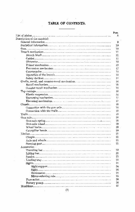
TABLE OF CONTENTS.
Page. List of plates... •. 8 Description'of the materiel:
General information 9 Statistical information 10 Gun 10 Breech mechanism 11
Breech block 11 Carrier . . 11 Obturator • 12 Primer mechanism 12 Percussion mechanism 12 Counterpoise 13 Operation of the breech . 13 Safety devices 14
Cradle, recoil, and counter-recoil mechanism 14 Recoil mechanism 15 Counter-recoil mechanism. 16
Top carriage 16 Elastic suspension 16 Traversing mechanism 17 Elevating mechanism 17
Chassis 18 Connection with the gun axle 18 Connection with the trails 18
Trails 19 Gun axle 20
Gun-axle spring * 20 Gun-axle wheel 20 Wheel brake 20 Caterpillar bands 20
Limber 21 Chassis 21 Axle and wheels 21 Steering gear 21
Accessories— Traveling bar '..'.' 22 Lifting bar 23 Spades , 23 Loading tray 23 Sights..... 24
Sight support 24 Sight -- 24 Goniometer 24 Mirror-referring rule ,. 25
Fuse setter - 26 Battery pump 26
Munitions 27 (5)
6
Page.
Care of the materiel 29 Gun section's duties 29 Chief mechanic's duties.. 29 Gun section— ,
Disassembling and assembling 30 Breech mechanism '. 30 Percussion mechanism 33 Safety device and primer holder 33 Wheels 33 Caterpillar bands 33
Daily maintenance 34 After traveling 34 After firing 34 Gun. - 35 Breech mechanism 35 Cradle 35 Sight support - 36 Top carriage - - 36 Traversing and elevating mechanism 36 Chassis 36 Trails .' 36-Gun axle 37 Wheels 37 Brakes 37 Limber 37 , Traveling bar 37 Spades. 37 Fuse setter 37
Rapid inspection. — 38 Traveling position - - 38 Firing position 39 Accessories .' , - 39
Battery mechanic— Recoil and counter-recoil systems 39
Filling the recoil cylinder 40 Emptying the automatic filler > 40 Emptying the counter-recoil reservoir 40 Filling the counter-recoil reserve - 41 Use of the screw filler 41
Disassembling and assembling 41 Counterpoise 41 Gun-axle spring 41 Limber spring - 41 Brake drum 41 Fuse setter - - 42
Complete cleaning and lubrication - - 42 Nomenclature of oil cups '. - 42 Removing copper deposit 42
Detailed inspection 43 Gun and breechblock 43 Cradle - - 43 Pointing mechanisms 43 Gun axle.. --• 44
7
Care of the materiel—Continued. Battery mechanics—Continued-
Detailed inspection—Continued. Page. Trails , 44 Wheels 44 Brake drum 44 Adjustment of the brakes 44 Limber 44 Reports rendered, 44
Testing the lines of sight . 45 For elevation 45 Calibrating a quadrant 45 For direction , 46
General information: . Painting artillery materiel 46
Oils for artillery materiel. 47 General suggestions 48
Nomenclature of parts of gun and carriage: Gun '. 49 Breech mechanism 49 Cradle 51 Top carriage 52 Chassis 53 Trails 54 Gun axle 55 Limber 56 Sight . 58 Accessories 59
Composition of battalion in French artillery materiel: Articles for the service of the piece—
Tools, equipment, and accessories for the service of the piece 61 Sight chest 62 Section armament chest. 62 Section tool and spare part chest 63 Caterpillar band chest 63
Articles for the service of the battery— Spare equipment and accessories 64 Sight spare part chest 64 Battery mechanics' tool chest 64 Recoil mechanism chest - 65 Spare assembly chest 65 Separate spare part chest 65
Tools and accessories— Artificer's tool chest 66 Wood and iron workers' tools and stores 1 67 Saddler's tools and stores 69 Construction tools 70 Illuminating materiel 70
Fire control and liaison materiel 71 Composition of battalion in United States materiel 72
LIST OF PLATES.
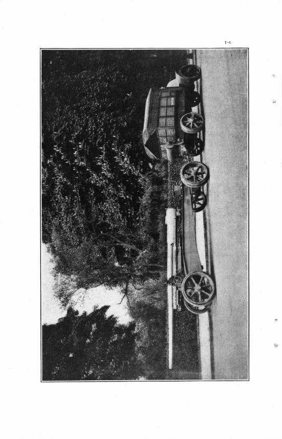
PLATE. I. Firing position, side elevation.
II. Traveling position, side elevation. III . Traveling position, plan. IV. Gun, longitudinal and transverse sections. V. Breech, rear elevation.
VI. Breech, right side elevation. VII. Breech, vertical section.
VIII. Breech, horizontal section. IX. Breech, safety device. X. Breech, counterpoise.
XI. Cradle. XII. Top carriage.
XIII. Sighting gear casing. XIV. Chassis and top carriage. XV. Limber.
XVI. Sight.

HANDBOOK OF THE 155-MM. FILLOUX GUN.
DESCRIPTION OF THE MATERIEL.
CHAPTER I.
GENERAL INFORMATION.
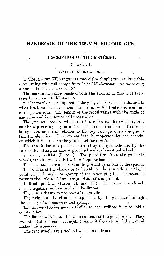
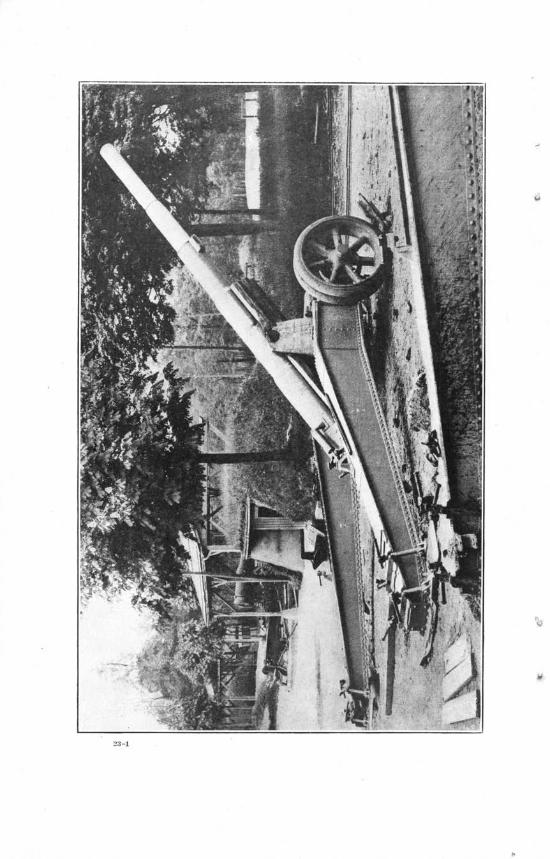
1. The 155-mm. Filloux gun. is a materiel with split trail and variable recoil, firing with full charge from 0° to 35° elevation, and possessing a horizontal field of fire of 60°.
The maximum range reached with the steel shell, model of 1915, type B, is about 16 kilometers.
2. The materiel is composed of the gun, which recoils on the cradle when fired, and which is connected to it by the brake and counter-recoil piston-rods. The length of the recoil varies with the angle of elevation and is automatically controlled.
The gun and cradle, which constitute the oscillating mass, rest on the top carriage by means of the cradle trunnions. The oscillating mass moves in relation to the top carriage when the gun is laid for elevation. The top carriage is supported by the chassis, on which it turns when the gun is laid for direction:.
The chassis forms a platform carried by the gun axle and by the two trails. The gun axle is provided with rubber-tired wheels.
3. Firing position (Plate I).—The piece fires from the gun axle wheels, which are provided with caterpillar bands.
The open trails are anchored in the ground by means of the spades. The weight of the chassis rests directly on the gun axle at a single
point only, through the agency of the pivot pin; this arrangement permits the axle to follow irregularities of the ground.
4. Koad position (Plates I I and III).—The trails are closed, locked together, and secured on the limber.
The gun is drawn to the rear of the cradle. The weight of the chassis is supported by the gun axle through ,
the agency of a transverse leaf spring. The limber steering gear is similar to that utilized in automobile
construction. The limber wheels are the same as those of the gun proper. They
are intended to receive caterpillar bands if the nature of the ground makes this necessary.
The rear wheels are provided with brake drums. (9)
10
STATISTICAL INFORMATION.
GUN.
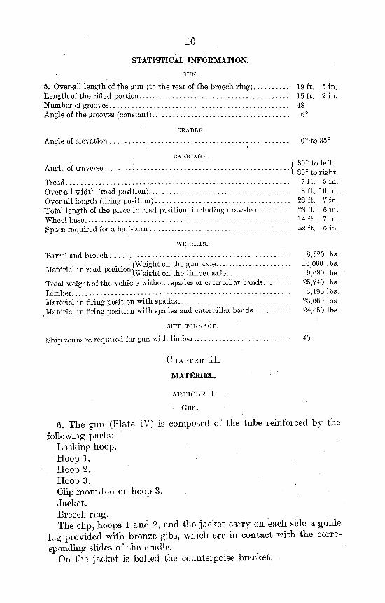
5. Over-all length of the gun (to the rear of the breech ring) 19 ft. 5 in. Length of the rifled portion 15 ft. 2 in. Number of grooves 48 Angle of the grooves (constant) 6°
CRADLE.
Angle of elevation . 0° to 35°
CARRIAGE.
A , • f 30° to left. Angle or traverse < OA0 , . , .
5 I 30° to right. Tread.. 7 ft. 5 in. Over-all width (road position) , 8 ft. 10 in. Over-all length (firing position) 23 ft. 7 in. Total length of the piece in road position, including draw-bar 28 ft. 6 in. Wheel base 14 ft. 7 in. Space required for a half-turn •.." 52 ft. 6 in.
WEIGHTS.
Barrel and breech - - ----- 8,520 lbs. n . . (Weight on the gun axle 16,080 lbs.
Materiel in road position j W e i g h t o n ^ l i m b e r ax]e_ _, Q m ^ Total weight of the vehicle without spades or caterpillar bands 25,740 lbs. Limber - - - - 3,190 lbs. Materiel in firing position with spades 23,660 lbs. Materiel in firing position with spades and caterpillar bands 24,650 lbs.
SHIP TONNAGE.
Ship tonnage required for gun with limber. 40
C H A P T E R II .
MATERIEL.
ARTICLE 1.
Gun.
6. The gun (Plate IV) is composed of the tube reinforced by the
following parts: Locking hoop. Hoop 1. Hoop 2. Hoop 3. Clip mounted on hoop 3.
Jacket. Breech ring. The clip, hoops 1 and 2, and the jacket carry on each side a guide
lug provided with bronze gibs, which are in contact with the corresponding slides of the cradle.
On the jacket is bolted the counterpoise bracket.
11
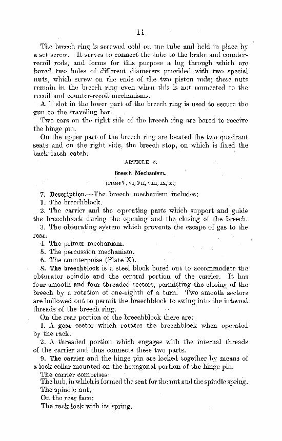
The breech ring is screwed cold on tne tube and held in place by a set screw. I t serves to connect the tube to the brake and counter-recoil rods, and forms for this purpose a. lug through which are bored two holes of different diameters provided with two special nuts, which screw on the ends of the,two piston rods; these nuts remain in the breech ring even when this is not connected to the recoil and counter-recoil mechanisms.
A T slot in the lower part of the breech ring is used to secure the gun to the traveling bar.
Two ears on the right side of the breech ring are bored to receive the hinge pin.
On the upper part of the breech ring are located the two quadrant seats and on the right side, the breech stop, on which is fixed the back latch catch.
A R T I C L E 2.
Breech Mechanism. (Plates V, VI, VII, VIII, IX, X.)
7. Description.—The breech mechanism includes: 1. The breechblock. 2. The carrier and the operating parts which support and guide
the breechblock during the opening and the closing of the breech. 3. The obturating system which prevents the escape of gas to the
rear. 4. The primer mechanism. 5. The percussion mechanism. 6. The counterpoise (Plate X) . 8. The breechblock is a steel block bored out to accommodate the
obturator spindle and the central portion of the carrier. I t has four smooth and four threaded sectors, permitting the closing of the breech by a rotation of one-eighth of a turn. Two smooth sectors are hollowed out to permit the breechblock to swing into the internal threads of the breech ring.
On the rear portion of the breechblock there are: 1. A gear sector which rotates the breechblock when operated
by the rack. 2. A threaded portion which engages with the internal threads
of the carrier and thus connects these two parts. 9. The carrier and the hinge pin are locked together by means of
a lock collar mounted on the hexagonal portion of the hinge pin. The carrier comprises: The hub, in which is formed the seat for the nut and the spindle spring. The spindle nut. On the rear face: The rack lock with its spring.
12
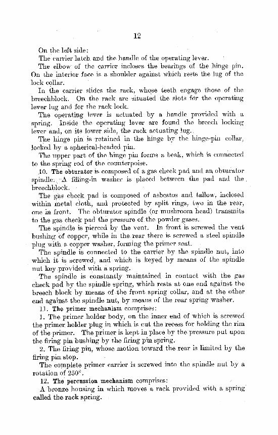
On the left side: The carrier latch and the handle of the operating lever. The elbow of the carrier incloses the bearings of the hinge pin.
On the interior face is a shoulder against which rests the lug of the lock collar.
In the carrier slides the rack, whose teeth engage those of the breechblock. On the rack are situated the slots for the operating lever lug and for the rack lock.
The operating lever is actuated by a handle provided with a spring. Inside the operating lever are found the breech locking lever and, on its lower side, the rack actuating lug.,
The hinge pin is retained in the hinge by the hinge-pin collar, locked by a spherical-headed pin.
The upper part of the hinge pin forms a beak, which is connected to the spring rod of the counterpoise.
.10. The obturator is composed of a gas check pad and an obturator spindle; A filling-in washer is placed between the pad and the . breechblock.
The gas check pad is composed of asbestos and tallow, inclosed within metal cloth, and protected by split rings, two in the rear, one in front. The obturator spindle (or mushroom head) transmits to the gas check pad the pressure of the powder gases.
The spindle is pierced by the vent. In front is screwed the vent bushing of copper, while in the rear there is screwed a steel spindle plug with a copper washer, forming the primer seat.
The spindle is connected to the carrier by the spindle nut, into which it is screwed, and which is keyed by means of the spindle nut key provided with a spring.
The spindle is constantly maintained in contact with the gas check pad by the spindle spring, which rests at one end against the breech block by means of the front spring collar, and at the other end against the spindle nut, by means of the rear spring washer.
11. The primer mechanism comprises: 1. The primer holder body, on the inner end of which is screwed
the primer holder plug in which is cut the recess for holding the rim of the primer. The primer is kept in place by the pressure put upon the firing pin bushing by the firing pin spring.
2. The firing pin, whose motion toward the rear is limited by the firing pin stop.
The complete primer carrier is screwed into the spindle nut by a rotation of 250°.
12. The percussion mechanism comprises: / A bronze housing in which moves a rack provided with a spring
called the rack spring.
13
The hammer, which can rotate 90° around its support to permit putting the primer holder in place.
The hammer support, which is provided with a gear sector engaging with the rack, and which rotates around the rack spindle.
A lanyard with wooden handle, which operates the hammer. 13. The counterpoise includes a cylinder fastened to the gun by
the counterpoise bracket and in which moves the spring rod. At one end of the spring rod there is fastened to it a collar, which presses against a spring surrounding the spring rod in the cylinder. At its other extremity, the spring rod is secured by a disengaging eye to the adjusting nut. The adjusting screw, located in the beak of the hinge pin, regulates the pressure of the counterpoise spring according to the angle of elevation of the gun, through its rotation by hand, which displaces the adjusting nut.
14. Operation of the breech.—When the breech is closed the threaded sectors of the breechblock are engaged with the threaded sectors of the breech ring.
In this position the operating lever is locked by its handle, which is held in place by the carrier latch. The lever thus prevents any rotation of the breechblock.
To open the breech one presses down upon the operating lever handle to disengage it from the carrier latch, then swings the lever to the right. During the first part of this movement the operating lever turns freely around the hinge pin, the lug of the lever operating the rack which causes the rotation of the breechblock. The threaded sectors of the block are thus disengaged from the threaded sectors of the breech ring. ' •
As soon as the breechblock is completely disengaged the rack strikes the rack lock and the carrier itself is swung by the rotation of the operating handle. In addition, by means of its shoulder, the carrier rotates with it its lock collar and hinge pin.
While the carrier is swinging open the rack lock, now released, moves upward under the pressure of its spring and enters into it's slot in the rack, rendering the rack immovable.
The upper extremity of the hinge pin, connected to the spring rod of the counterpoise, compresses the counterpoise spring during the opening of the breech.
At the end of the movement the back latch catch engages the catch of the operating lever and the breech is locked securely at the right side of the gun.
To close the breech one presses down on the operating lever handle in order to disengage the back latch catch, then swings the lever toward the left and thus brings the carrier to the breech face. This movement is made easier by the counterpoise, for the pressure of its spring tends to turn the hinge pin, and thus move the carrier by
14
means of the lock collar. The rack lock, whose outer extremity projects from the carrier, strikes the breech face, is pushed down into its socket, and frees the rack. The rotation1 of the operating lever, which at this moment turns freely around the hinge pin, now actuates the rack, which in turn rotates the block and engages its threaded sectors with the threaded sectors of the breech ring.
At the end of the motion of the operating lever its handle engages with the carrier latch and locks the breech closed.
When a round is fired the pressure produced on the mushroom head of the obturator spindle is transmitted by it to the gas check pad. The gas check pad increases in diameter when compressed and presses against the gas check seat, thus preventing the passage of the powder gases.
15. Safety devices:1
1. Safety device against firing before closing the breech: The safety lock (Plate IX) slides in the safety lock housing. In
it is screwed an operating finger, the end of which moves in a groove in the breechblock. The operating finger is constantly pressed down by the operating finger spring. The length of the safety lock and the dimensions of the groove in the breechblock are such that—
(a) When the breech is closed the safety device can be operated and permits the putting in place of the primer holder.
(b) When the primer holder is in place it is not possible to open the breech.
(c) When the primer holder is removed the breech can be opened freely.
2. Safety device against firing before completely screwing in the primer holder:
In the rim of the primer holder is cut a notch, which does not permit the hammer to strike the firing pin unless the primer holder is entirely screwed in.
ARTICLE 3.
Cradle, Recoil, and Counter-Recoil Mechanisms.
I. Cradle.
16. The cradle is a piece of forged steel which has the following functions:
(a) Guiding the gun during recoil. For this purpose the cradle forms two lateral guides, against
which slide the bronze gibs of the gun,
i Materiels at present in service (January, 1918) do not have safety device 1, but have instead a pin sliding in a seat in the carrier, which prevents the hammer from striking the firing pin until the breechblock threads ara completely engaged. At this moment a recess in the rear face of the breechblock is brought opposite, the end of the safety pin, permitting it to move freely when struck by the hammer,
15
(Z>) Connecting the gun to the top carriage and to the elevating and traversing mechanisms by the agency of the two trunnions forged integral with the cradle and of a vertical gear sector fastened on the underside of the cradle. This gear sec-tor communicates to the cradle the motion of the elevating mechanism carried by the top carriage.
(c) Encasing the parts of the recoil and counter-recoil mechanisms. For this purpose there are bored through the lower portion of the cradle three cylindrical holes. The largest hole contains the hydraulic brake. The two other holes contain the parts of the counter-recoil mechanism.
In addition, the cradle also carries: On the left side— The sight support fastened on the end of the trunnion. The automatic filler bolted to the forward end of the cradle,
integral with which is a mechanism for controlling the length of the recoil, connected by the recoil-regulating arm to a boss on the top carriage.
The orifice through which the recoil cylinder is filled, situated on the side and near the front of the automatic filler.
On the right side— The orifice through which the counter-recoil reservoir is filled.
This orifice is located near the rear end. On the rear face— The counter-recoil gauge placed at the rear of and slightly below
the axis of the larger counter-recoil cylinder. The orifice for emptying the reserve of the counter-recoil reservoir
placed below the gauge. On the front face— The orifice for emptying the oil from the recoil cylinder.
I I . Recoil mechanism.
17. The recoil mechanism is composed of a rod carrying a piston and of a counter rod. I t is filled with a special oil.
The recoil cylinder piston rod, connected to the lug of the breech ring, is movable and recoils with the gun. I t is hollow and carries at its front end a piston, through which are bored holes which connect the rear portion of the brake cylinder with the front portion, through the agency of grooves of variable depth, milled along the length of the counter rod.
The counter rod does not move longitudinally but can rotate within the rod. The amount of rotation is a function of the angle of elevation of the gun and is automatically controlled. As the angle of elevation increases, the recoil is shortened by diminishing
16
the area of the orifices through which, upon firing, the oil is forced. The rear extremity of the counter rod acts as a brake toward the close of counter recoil.
The automatic filler is a device which communicates with the recoil cylinder, and assures ,its being completely full of oil at all times. I t serves as a reservoir to permit the escape from the recoil cylinder of the excess of oil whenever the oil pressure is increased by the heat developed during firing. I t s capacity is about 1.7 quarts. A piston, prolonged toward the rear by a spindle, forms a gauge which enables one to ascertain at any time the quantity of oil contained in the automatic filler.
The recoil length is regulated by an arm fixed at one end to the top carriage. This arm operates a cam, which transforms the longitudinal motion which it receives when the gun is elevated into a rotation, which is transmitted to the counter rod of the recoil cylinder by means of two gear sectors.
I I I . Counter-recoil mechanism.
18. The counter-recoil mechanism consists of two cylinders; one contains a piston and a piston rod connected to the lug of the breech ring, while the other contains a mushroom valve and a diaphragm. The diaphragm separates the oil contained in the first cylinder and in a part of the second from the high pressure air which compels the return of the gun to battery after recoil.
Normally, there must always be a small reserve of oil between the diaphragm and the mushroom valve. Under these conditions the counter-recoil gauge projects 5 mm. from the rear face of the cradle. If there is no reserve the gauge does not project and it is necessary to fill the reserve of the counter-recoil reservoir.
ARTICLE 4.
(Plates XII, XIII , XIV.)
Top Carriage—Elevating and Traversing Mechanisms.
19. The cast-steel top carriage carries at its upper extremity the bearings for the trunnions of the cradle and rests on the circular racer of the chassis.
I ts principal purpose is to rotate the gun, through the agency of the cradle, in the laying for direction.
For this purpose it is pivoted on the chassis and is guided in its rotation by a circular projection which slides in a corresponding socket in the chassis. The rotation is made easier by an elastic suspension (Plate XIV), composed of two pivots, superposed and separated by a step and Belleville washers, whose pressure can be
17
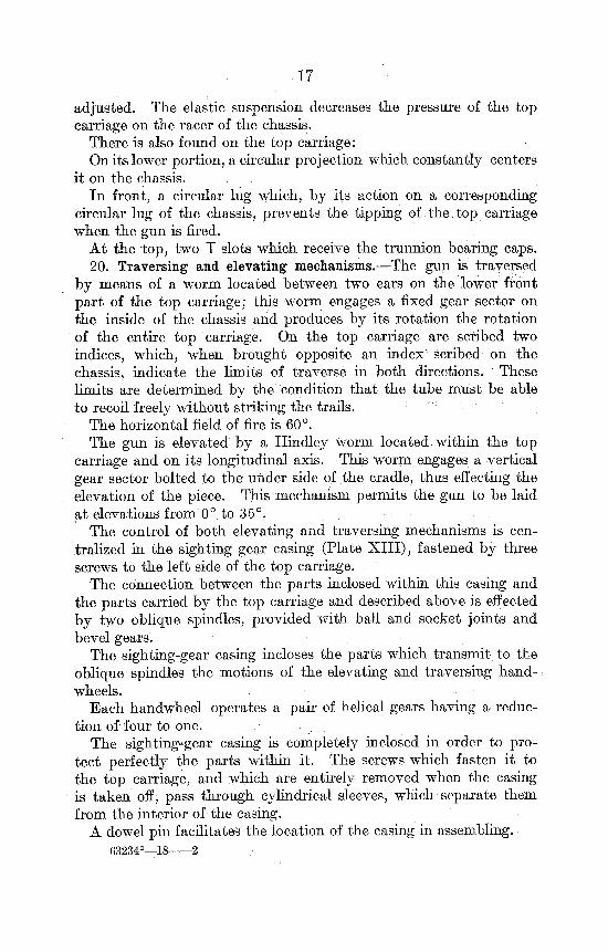
adjusted. The elastic suspension decreases the pressure of the top carriage on the racer of the chassis.
There is also found on the top carriage: On its lower portion, a circular projection which constantly centers
it on the chassis. In front, a circular lug which, by its action on a corresponding
circular lug of the chassis, prevents the tipping of the top carriage when the gun is fired.
At the top, two T slots which receive the trunnion bearing caps. 20. Traversing and elevating mechanisms.—The gun is traversed
by means of a worm located between two ears on the lower front part of the top carriage; this worm engages a fixed gear sector on the inside of the chassis and produces by its rotation the rotation of the entire top carriage. On the top carriage are scribed two indices, which, when brought opposite an index scribed on the chassis, indicate the limits of traverse in both directions. These limits are determined by the condition that the tube must be able to recoil freely without striking the trails.
The horizontal field of fire is 60°. The gun is elevated by a Hindley worm located within the top
carriage and on its longitudinal axis. This worm engages a vertical gear sector bolted to the under side of the cradle, thus effecting the elevation of the piece. This mechanism permits the gun to be laid at elevations from 0° to 35°.
The control of both elevating and traversing mechanisms is centralized in the sighting gear casing (Plate XI I I ) , fastened by three screws to the left side of the top carriage.
The connection between the parts inclosed within this casing and the parts carried by the top carriage and described above is effected by two oblique spindles, provided with ball and socket joints and bevel gears.
The sighting-gear casing incloses the parts which transmit to the oblique spindles the motions of the elevating and traversing hand-wheels.
Each handwheel operates a pair of helical gears having a reduction of four to one.
The sighting-gear casing is completely inclosed in order to protect perfectly the parts within it. The screws which fasten it to the top carriage, and which are entirely removed when the casing is taken off, pass through cylindrical sleeves, which separate them from the interior of the casing.
A dowel pin facilitates the location of the casing in assembling. 63234°—18 2
18
ARTICLE 5.
(Plate XIV.)
Chassis.
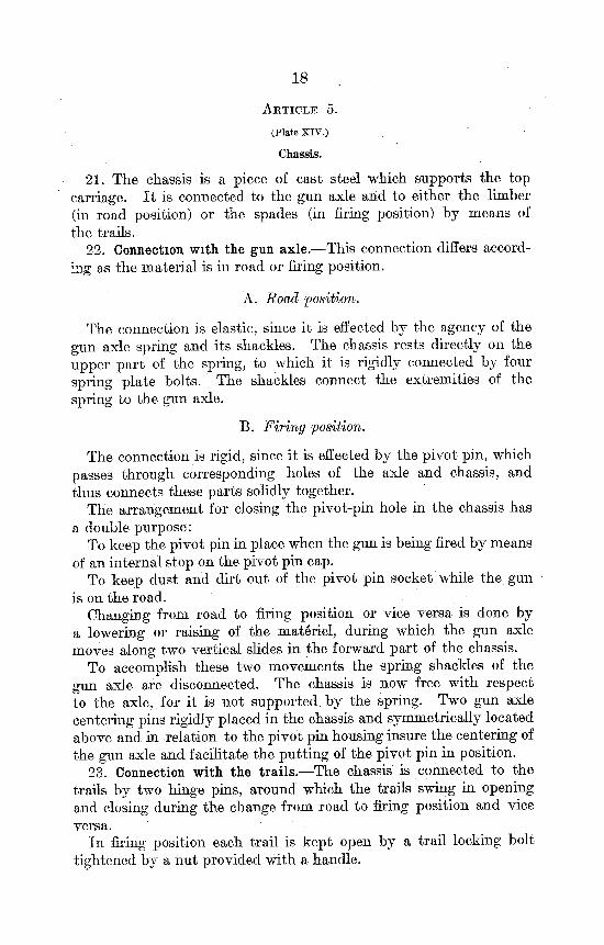
21. The chassis is a piece of cast steel which supports the top carriage. I t is connected to the gun axle and to either the limber (in road position) or the spades (in firing position) by means of the trails.
22. Connection with the gun axle.—This connection differs according as the material is in road or firing position.
A. Road position.
The connection is elastic, since it is effected by the agency of the gun axle spring and its shackles. The chassis rests directly on the upper part of the spring, to which it is rigidly connected by four spring plate bolts. The shackles connect the extremities of the spring to the gun axle.
B. Firing position.
The connection is rigid, since it is effected by the pivot pin, which passes through corresponding holes of the axle and chassis, and thus connects these parts solidly together.
The arrangement for closing the pivot-pin hole in the chassis has a double purpose:
To keep the pivot pin in place when the gun is being fired by means of an internal stop on the pivot pin cap.
To keep dust and dirt out of the pivot pin socket while the gun is on the road.
Changing from road to firing position or vice versa is done by a lowering or raising of the materiel, during which the gun axle moves along two vertical slides in the forward part of the chassis.
To accomplish these two movements the spring shackles of the gun axle are disconnected. The chassis is now free with respect to the axle, for it is not supported by the spring. Two gun axle centering pins rigidly placed in the chassis and symmetrically located above and in relation to the pivot pin housing insure the centering of the gun axle and facilitate the putting of the pivot pin in position.
23. Connection with the trails.—The chassis is connected to the trails by two hinge pins, around which the trails swing in opening and closing during the change from road to firing position and vice versa.
In firing position each trail is kept open by a trail locking bolt tightened by a nut provided with a handle.
19
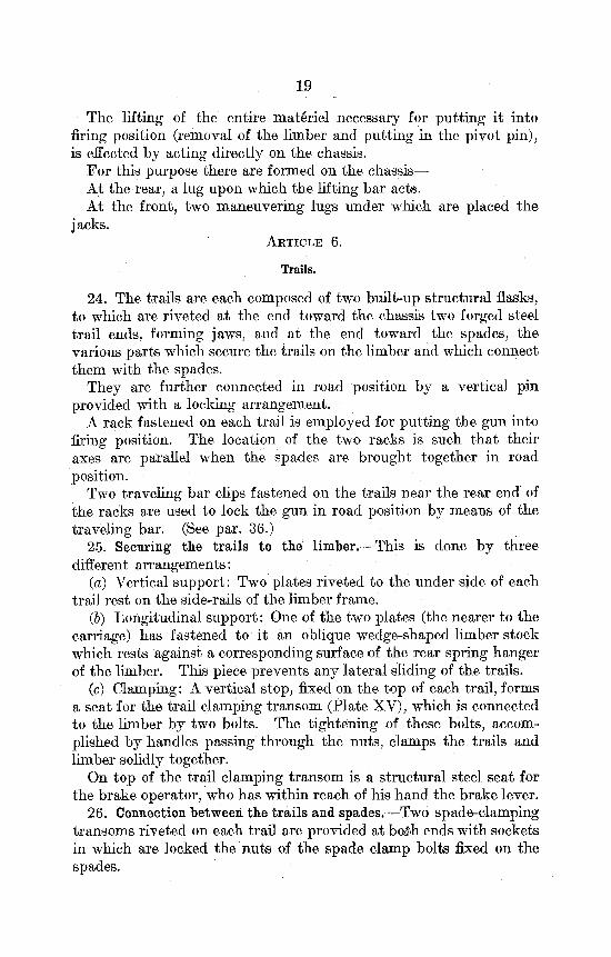
The lifting of the entire materiel necessary for putting it into firing position (removal of the limber and putting in the pivot pin), is effected by acting directly on the chassis.
For this purpose there are formed on the chassis— At the rear, a lug upon which the lifting bar acts. At the front, two maneuvering lugs under which are placed the
jacks. ARTICLE 6.
Trails.
24. The trails are each composed of two built-up structural flasks, to which are riveted at the end toward the chassis two forged steel trail ends, forming jaws, and at the end toward the spades, the various parts which secure the trails on the limber and which connect them with the spades.
They are further connected in road position by a vertical pin provided with a locking arrangement.
A rack fastened on each trail is employed for putting the gun into firing position. The location of the two racks is such tha t their axes are parallel when the spades are brought together in road position.
Two traveling bar clips fastened on the trails near the rear end of the racks are used to lock the gun in road position by means of the traveling bar. (See par. 36.)
25. Securing the trails to the limber.—This is done by three different arrangements:
(a) Vertical support: Two plates riveted to the under side of each trail rest on the side-rails of the limber frame.
(&) Longitudinal support: One of the two plates (the nearer to the carriage) has fastened to it an oblique wedge-shaped limber stock which rests against a corresponding surface of the rear spring hanger of the limber. This piece prevents any lateral sliding of the trails.
(c) Clamping: A vertical stop, fixed on the top of each trail, forms a seat for the trail clamping transom (Plate XV), which is connected to the limber by two bolts. The tightening of these bolts, accomplished by handles passing through the nuts, clamps the trails and limber solidly together.
On top of the trail clamping transom is a structural steel seat for the brake operator, who has within reach of his hand the brake lever.
26. Connection between the trails and spades.—Two spade-clamping transoms riveted on each trail are provided at bodh. ends with sockets in which are locked the nuts of the spade clamp bolts fixed on the spades.
20
ARTICLE 7.
Gun Axle—Wheels—Wheel Brake.
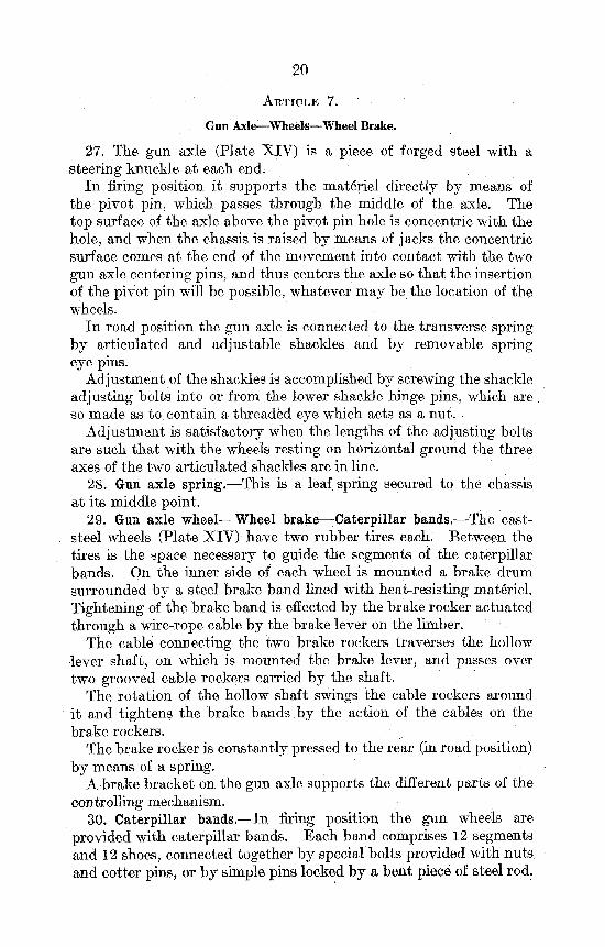
27. The gun axle (Plate XIV) is a piece of forged steel with a steering knuckle at each end.
In firing position it supports the materiel directly by means of the pivot pin, which passes through the middle of the axle. The top surface of the axle above the pivot pin hole is concentric with the hole, and when the chassis is raised by means of jacks the concentric surface comes at the end of the movement into contact with the two gun axle centering pins, and thus centers the axle so that the insertion of the pivot pin will be possible, whatever may be the location of the wheels.
In road position the gun axle is connected to the transverse spring by articulated and adjustable shackles and by removable spring eye pins.
Adjustment of the shackles is accomplished by screwing the shackle adjusting bolts into or from the lower shackle hinge pins, which are so made as to contain a threaded eye which acts as a nut.
Adjustment is satisfactory when the lengths of the adjusting bolts are such that with the wheels resting on horizontal ground the three axes of the two articulated shackles are in line.
28. Gun axle spring.—This is a leaf spring secured to the chassis at its middle point.
29. Gun axle wheel—Wheel brake—Caterpillar bands.—The cast-steel wheels (Plate XIV) have two rubber tires each. Between the tires is the space necessary to guide the segments of the caterpillar bands. On the inner side of each wheel is mounted a brake drum surrounded by a steel brake band lined with heat-resisting materiel. Tightening of the brake band is effected by the brake rocker actuated through a wire-rope cable by the brake lever on the limber.
The cable connecting the two brake rockers traverses the hollow lever shaft, on which is mounted the brake lever, and passes over two grooved cable rockers carried by the shaft.
The rotation of the hollow shaft swings the cable rockers around it and tightens the brake bands by the action of the cables on the brake rockers.
The brake rocker is constantly pressed to the rear (in road position) by means of a spring.
A brake bracket on the gun axle supports the different parts of the controlling mechanism.
30. Caterpillar bands.—In firing position the gun wheels are provided with caterpillar bands. Each band comprises 12 segments and 12 shoes, connected together by special bolts provided with nuts and cotter pins, or by simple pins locked by a bent piece of steel rod.
21
There are two kinds of segments having different lengths. The common band is composed of 11 short elements and. 1 long element. When, in consequence of the wear of the pins, the caterpillar band becomes too loose on the wheel, the long element is replaced by a short one.
ARTICLE 8. Limber.
(Plate XV.)
31. The limber makes possible the transportation on the road of the materiel as a single vehicle. I t is composed of—
A chassis upon which rest the trails. An axle with its spring. Two wheels. • The steering gear of the vehicle. 32. The limber chassis is composed of two side rails connected by
two transoms. Each one of the side rails is provided at each end with spring hangers. The forward transom is a piece of cast steel in which is formed the socket for the pintle bolt.
The trails rest on the side rails of the limber; directly above these are spring hangers and the rear ends of the forward spring hangers. Bearing plates are riveted to the under side of the trails to form the support.
33. The axle of the limber of I section has at both ends steering knuckles, through which pass the vertical steering knuckle pins which form an essential part of the steering gear. On the upper flange of the section are two spring pads which support the two leaf springs of the limber. Two spring clips form the connection between each one of these springs and the axle.
34. Wheels.—The wheels are the same as those of the gun axle, except that they do not carry brake drums.
35. Steering gear.—The steering gear is similar to that employed in automobile construction. I t comprises:
A drawbar, having at one end an eye which engages with the pintle hook of the tractor.
A drawbar tie, connected to the drawbar by a bolt and oscillating around the pintle bolt in the chassis of the limber.
Two symmetrical steering tie rods connected to the rear portion of the drawbar tie and actuating two steering arms which work the steering knuckles.
The drawbar tie, the steering tie rods, and. the steering arms are connected by joints having the necessary flexibility for following the oscillations of the springs as well as the irregularities of the road. Two keys, one locking the drawbar tie with respect to the drawbar, the other locking both these parts with relation to the limber chassis, facilitate the maneuver of the limber by hand when it is separated from the rest of the vehicle.
22
CHAPTER I I I .
ACCESSORIES.
A R T I C L E 1.
Traveling Bar.
36. The traveling bar is employed for carrying the gun from battery to road positions, and vice versa, and for supporting the rear of the gun and locking it during transportation.
The traveling bar is composed of two side rails connected by transoms, the end transoms being of bronze and forming bearings. Each end transom carries an operating pinion whose spindle is square and receives the pawl lever.
(a) Connection between the traveling bar and the gun while the latter is being put into firing position.
The clamping screw has at its lower end a clamping lever and is mounted in the clamping screw housing of the traveling bar. On the upper end of the clamping screw is a nut having the form of a T. When this nut engages the corresponding T slot in the breech ring, turning the clamping screw connects the gun- and the traveling bar rigidly.
The movement of the gun from road to firing position and vice versa is effected by operating the pinions of the traveling bar, which engage the racks carried by the trails. During this motion the bronze end transoms of the traveling bar slide on the upper faces of the racks.
(b) Locking the gun in road position. At the end of the rearward motion of the traveling bar the screws
of the traveling bar clips fastened on the trails are brought opposite the corresponding sockets in the locking transoms. The tightening of these screws renders the traveling bar immovable and prevents any motion of the gun or traveling bar on the trails during transportation.
(c) Locking device of the traveling bar. At the end of the forward motion of the traveling bar the breech
ring is connected to the brake by the recoil and counter-recoil piston rod nuts.
A locking device prevents the removal of the traveling bar before the nut of the recoil piston rod is entirely tightened. In addition, the trails can not be separated when the traveling bar is in position, so that it is not possible to put the gun into firing position or to commence firing before having connected the gun to the recoil mechanism.
The locking device consists of a latch, whose finger engages in a groove on the under side of the breech ring. This latch ceases to act when the nut of the recoil piston rod in being tightened presses it down, but does not cease completely to act until the nut is entirely tightened.

23
ARTICLE 2.
Lifting Bar.
37. The lifting bar and the jacks swing the entire materiel around the gun axle as an axis. This operation permits the removal of the limber and, after having spread the trails, the placing of their extremities in the ground, or vice versa. The lifting bar is composed of an I-beam, havkig at each end an extension under which the jacks are placed.
On top and in the middle there is a lug which fits in the corresponding socket of the rear maneuvering lug of the chassis. A pin keeps the lug of the lifting bar in its socket during the operations of maneuvering.
ARTICLE 3.
Spades.
38. The spades are composed of a top plate and a share of structural, steel plate, forming an angle of 80° with each other, and stiffened by two braces.
There is found on the top plate: 1. A stop against which the extremity of the trail rests during
recoil. 2. An increased thickness of plate, which rests in a corresponding
socket of the trail and serves as a stop for the trail at the moment of counter recoil.
3. The front and rear spade clamp bolt hinges, to which are connected the spade clamp bolts, each having a nut provided with an operating handle. The nut can be locked in the corresponding socket of the spade clamping transom, thus connecting the spades securely to the trails.
ARTICLE 4.
Loading Tray.
39. The loading tray is composed of a cylindrical body of steel plate open on the upper side and provided with two handles. At the rear is placed a stop for the base of the shell.
At the front end is a centering cone of bronze which insures the centering of the loading tray in relation to the interior of the gun, and which serves as a support while the gun is being loaded.
Two lateral bronze guides slide on the sectors of the breech ring threads, guiding the loading tray longitudinally while it is being put in place.
A bronze position lug engaging with a socket in the breech ring prevents the loading tray from slipping to the rear. Two bronze protectmg plates on the cylindrical body in front of the handles prevent injury to the breech ring threads.
24
A E T I C L B 5.
Sights.
(Plate XVI.)
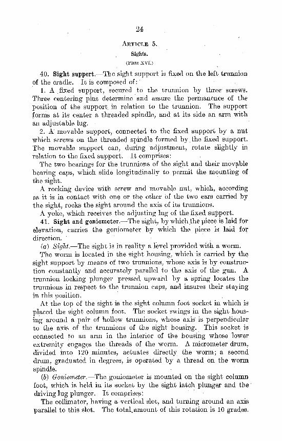
40. Sight support.—The sight support is fixed on the left trunnion of the cradle. I t is composed of:
1. A fixed support, secured to the trunnion by three screws. Three centering pins determine and assure the permanence of the position of the support in relation to the trunnion. The support forms at its center a threaded spindle, and at its side an arm with an adjustable lug.
2. A movable support, connected to the fixed support by a nut which screws on the threaded spindle formed by the fixed support. The movable support can, during adjustment, rotate slightly in relation to the fixed support. I t comprises:
The two bearings for the trunnions of the sight and their movable bearing caps, which slide longitudinally to permit the mounting of the sight.
A rocking device with screw and movable nut, which, according as it is in contact with one or the other of the two ears carried by the sight, rocks the sight around the axis of its trunnions.
A yoke, which receives the adjusting lug of the fixed support. 41. Sight and goniometer.—The sight, by which the piece is laid for
elevation, carries the goniometer by which the piece is laid for direction.
(a) Sight.—The sight is in reality a level provided with a worm. The worm is located in the sight housing, which is carried by the
sight support by means of two trunnions, whose axis is by construction constantly and accurately parallel to the axis of the gun. A trunnion locking plunger pressed upward by a spring locates the trunnions in respect to the trunnion caps, and insures their staying in this position.
At the top of the sight is the sight column foot socket in which is placed the sight column foot. The socket swings in the sight housing around a pah- of hollow trunnions, whose axis is perpendicular to the axis of the trunnions of the sight housing. This socket is connected to an arm in the interior of the housing whose lower extremity engages the threads of the worm. A micrometer drum, divided into 120 minutes, actuates directly the worm; a second drum, graduated in degrees, is operated by a thread on the worm spindle.
(h) Goniometer.—The goniometer is mounted on the sight column foot, which is held in its socket by the sight latch plunger and the driving lug plunger. I t comprises:
The collimator, having a vertical slot, and turning around an axis parallel to this slot. The total, amount of this rotation is 10 grades.
25
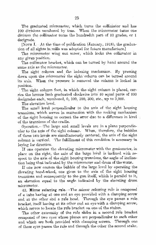
The graduated micrometer, which turns the collimator and has 100 divisions numbered by tens. When the micrometer turns one division the collimator turns the hundredth part of 10 grades, or 1 decigrade.
[NOTE I.—At the time of publication (January, 1918), the graduation of all sights in mills was adopted for future manufacture.]
The micrometer wing nut screw, which locks the collimator in any given position.
The collimator bracket, which can be turned by hand around the same axis as the micrometer.
The sight column and the indexing mechanism. By pressing down upon the micrometer the sight column can be turned around its axis. When the pressure is removed the column is locked in position.
1 The sight column foot, in which the sight column is placed, carries the bronze limb graduated clockwise into 40 equal parts of 100 decigrades each, numbered, 0, 100, 200, 300, etc., up to 3,900.
The elevation level. The small level perpendicular to the axis of the sight housing
trunnions, which serves in connection with the rocking mechanism of the sight housing to correct the error due to a difference in level of the trunnions of the cradle.
Operation.-—The large and small levels are in a plane perpendicular to the axis of the sight column. When, therefore, the bubbles of these two levels are simultaneously centered, the axis of the sight column is vertical. The fulfillment of this condition is necessary in laying for direction.
If one operates the elevating micrometer with the goniometer, in place on the sight, the axis of the large level is inclined with respect to the axis of the sight housing trunnions, the angle of inclination being that indicated by the micrometer and drum of the worm.
If one now centers the oubble of the large level by operating the elevating hand-wheel, one gives to the axis of the sight housing trunnions and consequently to the gun itself, which is parallel to it, an elevation equal to the angle indicated by the elevating drum micrometer.
42. Mirror referring rule.—The mirror referring rule is composed of a tube having at one end an eye provided with a clamping screw and at the other end a rule head. Through the eye passes a rule, bracket, itself having at its other end an eye with a clamping screw, which serves to locate the rule bracket on one of the stakes.
The other extremity of the rule slides in a second rule bracket composed of two eyes whose planes are perpendicular to each other and which are both provided with clamping screws. Through one of these eyes passes the rule and through the other the second stake.
26
A R T I C L E 6.
Fuze Setter.
(Model of 1917.)
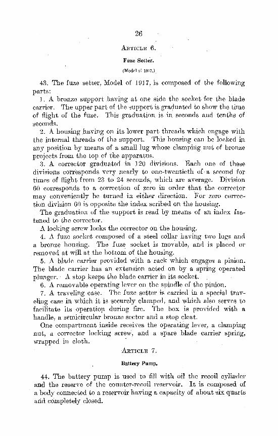
43. The fuze setter, Model of 1917, is composed of the following parts:
1. A bronze support having at one side the socket for the blade carrier. The upper part of the support is graduated to show the time of flight of the fuze. This graduation is in seconds and tenths of seconds.
2. A housing having on its lower part threads which engage with the internal threads of the support. This housing can be locked in any position by means of a small lug whose clamping nut of bronze projects from the top of the apparatus.
3. A corrector graduated in 120 divisions. Each one of these divisions corresponds very nearly to one-twentieth of a second for times of flight from 23 to 24 seconds, which are average. Division 60 corresponds to a correction of zero in order tha t the corrector may conveniently be turned in either direction. For zero correction division 60 is opposite the index scribed on the housing.
The graduation of the support is read by means of an index fastened to the corrector.
A locking screw locks the corrector on the housing. 4. A fuze socket composed of a steel collar having two lugs and
a bronze housing. The fuze socket is movable, and is placed or removed at will at the bottom of the housing.
5. A blade carrier provided with a rack which engages a pinion. The blade carrier has an extension acted on by a spring operated plunger. A stop keeps the blade carrier in its socket.
6. A removable operating lever on the spindle of the pinion. 7. A traveling case. The fuze setter is carried in a special trav
eling case in which it is securely clamped, and which also serves to facilitate its operation during fire. The box is provided with a handle, a semicircular bronze sector and a stop cleat.
One compartment inside receives the operating lever, a clamping nut, a corrector locking screw, and a spare blade carrier spring, wrapped in cloth.
ARTICLE 7.
Battery Pump.
44. The battery pump is used to fill with oil the recoil cylinder and the reserve of the counter-recoil reservoir. I t is composed of a body connected to a reservoir having a capacity of about six quarts and completely closed.
27
The piston of the pump is actuated by a lever which can be pivoted in. two positions. This makes the operation easier when it would otherwise become too difficult.
A flexible copper pipe forms the communication between the reservoir and the orifices of the cradle, by means of a special connection. This connection is composed of a threaded part fastened to the end of the pipe and of a movable part which, at one end, screws into the filling orifice of the cradle and at the other end screws on the fixed part.
The reservoir has also a check valve, which prevents the escape of oil in case the pump is upset, and permits the filling of the reservoir. In doing this a funnel with wire mesh filter must be used in order that the brake oil introduced may be absolutely free from all impurities. The operation of filling must be made in a place as free from dust as possible.
The pump is inclosed within a chest, which protects it and holds in addition: •
The operating lever spindle. A spiral pipe. A funnel with wire mesh filter. An oil extractor (75-mm. materiel). A small graduated rule. A 21 and 35-mm. double-ended wrench. An operating lever extension. A screw filler. A right-angled screw driver. The oil extractor is screwed into the filling orifices of the cradle
when it is desired to empty the brake or the counter-recoil reserve and on the recoil cylinder draining orifice when it is desired to fill the recoil cylinder.
The screw filler is a reserve in case the pump gets out of order.
CHAPTER IV.
MUNITIONS.
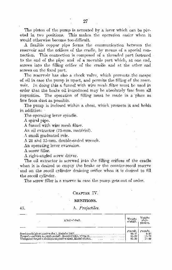
45. A. Projectiles.
Kind of shell. Weight of shell.
Weight of ex
plosive.
Semisteelhigh explosive shell, Modelof 1917 Forged steel high explosive shell, Model of 1915, Type B. . Elongated forged steel high explosive shell, Model of 1914.
Pounds. 98.87 95.02 95.30
Pounds. 9.92
15.70 22.49
28
B. Powder charges.
46. The range tables give full information concerning the powder charges.
C. Primers.
47. The primer used is the primer V2. If these can not be obtained the Marine primer, Model of 1906, may be used.
D. Fuzes.
48. The following fuzes are used with this materiel: Detonating percussion fuze 24/31 I.A.L., Model of 1916, giving
instantaneous explosion. Detonating percussion fuze 24/31, Model of 1899-1915, in three
forms: (a) Without delay. . . .. (&) With short delay. (c) With long delay. Detonating time and percussion fuze 24/31 L.D., Model of J917. All these fuzes are used with relay gaines, Model of 1915, Type A,
for the semisteel shell, Model of 1917, and Type C for the steel shells, Model of 1915, Type B, and Model of 1914.
CARE OF MATERIEL.
C H A P T E R I .
GENERAL RULES.
49. Inspection, care, and repair of the materiel of the 155-mm. Filloux gun are performed by the following:
(a) The gun section, under the chief of section. (b) The chief mechanic, under the supervision of the battery
commander. (c) The repair shops.
A. Gun section.
50. The chief of the gun section is responsible for— Daily cleaning, lubrication, and inspection of all materiel. Replacing damaged parts authorized by the present regulations—
breech, primer holder, obturator spindle, gas check pad, wheels, caterpillar bands, and brake-operating mechanism.
Making sure that the recoil and counter-recoil reservoirs are full. For the above operations the spare parts and tools are taken from
the gun repair chest. The instructions concerning the upkeep of materiel and the replac
ing of damaged parts are given in the present regulations. The disassembling of parts and the making of repairs not pre
scribed in these regulations are absolutely prohibited. The chief of section records all work done and repairs made in his
data book. B. Chief mechanic.
51. The chief mechanic under the battery commander is responsible for—
The detailed inspection, cleaning, and lubrication of materiel. The making of repairs during firing, when the repairs can not be
made by the gun section. The replacing of parts as prescribed in the present regulations. Filling the recoil and counter-recoil reservoirs. Testing the lines of sight and the sighting apparatus. The removal of copper deposits from the bores. Care of the ropes. For the above operations, the tools are kept in the battery tool
chest, and the repair parts in the battery chests or in the tractors. (29)
30
The instructions concerning the upkeep of materiel and the replacing of damaged or broken parts, the testing of recoil and counter-recoil mechanisms, and the sights, are given in the present regulations;
I t is absolutely forbidden to disassemble any parts or make repairs not prescribed in these regulations.
52. In general, the battery commander is authorized to replace all parts for which he may have spares.
The battery is forbidden to perform any disassembling not authorized by these regulations, or any repairs involving the following operations:
Adjusting the lines of sight. File work. Forge work. 53. I t is forbidden to polish any parts of the gun or carriage.
No cleaning or lubricating materiels may be used except those issued for the purpose, such as hydroline or special recoil mechanism oil, engine oil No. 1, clock oil, slushing oil, kerosene, etc. The use of any similar • materiels, or of brick powder, emery, etc., is absolutely prohibited.
CHAPTER II .
GUN SECTION.
ARTICLE 1.
Disassembling and Assembling.
54. No parts of the materiel should be disassembled unless it is necessary.
55. I t is forbidden to disassemble any part of the materiel by a method other than that prescribed in these regulations, or to disassemble any part not prescribed in these regulations.
56. The parts of the materiel tha t may be disassembled by the gun section are the breech mechanism, complete, composed of the breechblock, the carrier, the rack, the obturator spindle, the gas check pad, and the spindle plug, the percussion mechanism, the primer holder, the wheels, the wheel brake mechanism, and the caterpillar bands.
I . Breech mechanism.
57. General directions.—The different parts of the breech mechanism must be handled with great care. The breechblock or the obturator spindle, if dropped, may be damaged seriously enough to prevent the proper functioning of the mechanism.
The different parts, and especially the gas check pad and the obturator spindle, must be kept free from dirt and always placed on a clean cloth, never on the ground.
31
Before removing the breechblock from the carrier the obturator spindle must be removed in order that the gas check pad rings may not be injured.
Before assembling the parts they must be carefully cleaned and well oiled. .
In case any part of the breech mechanism is found to be burred or to be cutting, call immediately upon the battery chief mechanic to correct the difficulty or to obtain the services of the mobile repair shop. The smooth operation of the breech mechanism depends almost entirely upon the condition of the bearing surfaces.
The use of a file upon the threads of the breechblock or of the breech recess, except by a mechanic of the mobile repair shop, is prohibited.
The use of any emery cloth except crocus cloth upon any part of the breech mechanism, except by a mechanic of the mobile repair shop, is prohibited. Crocus cloth should be used very sparingly and only upon the special authorization of an officer.
(A) Disassembling the breech.
58. (1) Place the gun approximately horizontal. Open the breech. Pull out the spindle nut key as far as possible. (In order to do this, press down the key spring and pry under the heel of the key with a screw driver.)
Unscrew the obturator spindle, using the special wrench provided. In doing this, hold the spindle nut in its socket. Remove the obturator spindle carefully, with the obturator pad
and its washer. Remove the spindle nut, at the same time pulling back the hammer. Remove the gas check pad from the obturator spindle. Unscrew the spindle plug with its washer if it is necessary to
change the latter. (2) Free the locking lever from the back latch catch by pressing
the handle down and turn the breech to the left until the first threads of the breechblock are nearly engaged with the threads of the breech ring.
Insert between the shoulder of the counterpoise spring rod and the rear end of the counterpoise cylinder the spacing clip. Then slowly continue the rotation of the breech and disconnect the counterpoise when the adjusting nut is at the center of the spring-rod eye.
(3) Open the breechblock and push the rack lock as far as possible into its seat. By means of the operating lever, rotate the block a quarter of a turn as in opening the breech. When this is done the lever and rack are disconnected. Then turn the block by hand in the direction of opening until the rack is free.
32
Remove the rack. Remove the rack lock and its spring. (4) Support the breechblock by means of a rope, or by a bar
passed through it, and unscrew it from the carrier. Remove the spindle spring with the front spring collar, the front spring washer, and the rear spring washer.
(5) Support th.e carrier by means of a rope or bar. Remove the pin with spherical head which secures the hinge pin collar.
Remove the hinge pin collar and remove the hinge pin. Remove the operating lever. Remove the carrier and the lock collar.
(B) Assembling the breech.
59. (1) Insert the lock collar in its seat on the carrier. • (2) Place the carrier parallel to the axis of bore, supporting it by means of a rope or bar.
(3) Insert the operating lever. (4) Insert the hinge pin in the lock collar in such a way that the
counterpoise spring rod may be in the direction of the adjusting beak of the hinge pin. Push the hinge pin completely down.
(5) Pu t in place the hinge pin collar and secure it by means of the pin.
(6) Place in the carrier.the rear spring washer, the spindle spring, and the front spring washer, holding them together with heavy grease. Place the front spring collar in the breechblock. Lift the breechblock by means of a rope or bar. Screw it into the carrier carefully and completely.
(7) Insert the rack lock and spring. (8) Insert the rack, keeping the lock forced down in its seat, and
slightly turning the breechblock so as to permit the rack to pass freely. Bring the block and rack each opposite its index.
(9) Move the operating lever until the lug is in its seat in the rack. Turn the breechblock by hand so as to allow the rack and operating lever to reach the closing position. Release the rack lock spring and bring back the breechblock to the open position by operating the lever without moving the carrier.
(10) Place the spindle nut in its seat. Place the gas check pad on the obturator spindle. Screw the obturator spindle up completely at the same time holding the spindle nut in its seat. (If necessary, screw in the spindle plug with its washer before mounting the obturator spindle.) Push in the spindle nut key when the keyway in the obturator spindle is opposite the keyway in the nut.
(11) Close the breech. Connect the counterpoise spring rod with the adjusting nut in the beak of the hinge pin. Open the breech and remove the spacing clip. Close the breech.
33
I I . Percussion mechanism.
60. To disassemble the percussion mechanism, push with the special screw driver on the rack-lock bushing, at the same time holding the hammer. Turn the bushing one quarter of a turn so as to free it from the lugs on the end of the rack. Remove the bushing, keeping the spring in place. Remove the spring.
Pull the firing lanyard as far as possible so as to bring the lug of the rack spindle opposite its seat in the upper part of the housing. Remove the rack spindle upward, using a hammer and bronze drift pin, if necessary. Remove the hammer and its support.
To assemble, perform the above operations in the inverse order.
I I I . Safety device and primer holder.
61. To disassemble the safety device, press upward on the spring socket with a screw driver, in order to disengage the spring from the operating finger. Turn the operating finger one-quarter of a revolution to the left, remove the spring, and unscrew the operating finger completely. Lift out the safety lock.
To disassemble the primer holder, unscrew the firing pin stop, then remove the firing pin and firing pin spring.
IV. Wheels.
62. To remove a wheel.—The disassembling of the gun axle wheels is more easily performed when the gun is in traveling position. Block the opposite wheel. Slightly raise the wheel by means of a jack set against the upper part of the rim or the hub. Place blocks and half blocks under the axle. Lower the axle until it rests on the blocks and remove the jacks.
Unscrew the hub cap and remove the grease. Remove the cotter pin and unscrew the lock nut. Rotate the wheel slowly while removing it.
To mount the wheel reverse the operation. [NOTE.—In removing a gun wheel, first disconnect the brake drum
from the brake bracket by removing the adjusting bolt spindle and the connecting pin between the link and lower brake band end. Free the band from the drum.]
V. Caterpillar bands.
63. To remove a shoe from a band.—Remove the split pins and nuts fastening the pins and remove the pins. Clean and grease the pins before replacing them in their housings.
63234°—18 3
34
ARTICLE 2.
Daily Maintenance—Rapid Inspection.
A. Daily maintenance.
64. I t is essential that the materiel be cared for daily. This does not require skilled mechanics, but can be done by any cannoneer, who should know how to disassemble all authorized parts.
65. (1) After traveling.—The materiel must be cleaned immediately upon arrival. After the cleaning is completed the following operations must be performed:
(a) Clean and grease the hinge pins of both parts of the draw bar and of the limber steering mechanism.
(&) Clean and grease the limber steering knuckles. (c) Clean the spade clamp bolt hooks, the lower ends of the trail
locking bolts, the spade clamping transoms, the spade clamp bolts, and the traveling bar locking screws.
(d) Clean and grease the ends of the recoil and the counter-recoil piston rods and the bronze gibs of the gun.
(e) Clean and grease the elevating gear sector and the recoil regulating arm.
if) Clean and oil the breech mechanism, the percussion mechanism, and the sight support.
(g) Clean the wheel brake operating mechanism. (h) Clean the top carriage drain holes. Qc) Clean the caterpillar bands. (2) After firing.—The following operations must be performed: (a) Clean and slush the external parts of the gun; wash, dry, and
slush the bore, powder chamber, and breech of the gun. (6) Clean and grease the sliding parts of the gun and cradle. (c) Clean and grease the elevating and traversing mechanisms and
the sights. (d) Test the quantity of oil in the recoil cylinder and counter-
recoil reservoir. The different parts of the materiel are cleaned and lubricated
according to the following directions: 66. Oil cups.—An oil cup is placed at the entrance to each oil
hole except Nos. 15 and 16. Raise the milled head and with an oiler pour the necessary amount
of oil into the hole slowly so as to allow the oil to circulate. At the same time operate the mechanism that is being oiled so as to allow the oil to reach all its parts. Keep all oil cups and oil holes clean and free at all times. Use only engine oil No. 1 or lubricating oil for this purpose.
35
67. The gun.—The gun being in firing position, the breech opened or removed.
To clean the bore, depress the gun as far as possible and pour water or kerosene into the bore and powder chamber; sponge the bore with the cleaning sponge until the water or kerosene comes out clear. Dry by means of burlap placed, on the rammer and slush with the greasing sponge.
Clean the breech recess with a sponge and dry each thread carefully. Oil with a brush. This must be done immediately after firing, when antiflash preparations are used. In this case it may be necessary to remove the residue with hot water of kerosene and then to oil.
Clean and slush very slightly the quadrant seats. If they are rusted, remove the rust, using kerosene and a bit of wood. Never use emery, sand, or similar substances for this purpose. If kerosene will not remove the rust, the regimental repair squad must be called on to clean the quadrant seats, for they must generally be readjusted.
Clean and oil the bronze gibs of the gun. 68. The breechblock.—The breechblock should, whenever possible,
be disassembled before it is cleaned. Wash the different parts with water or kerosene, dry thoroughly, and oil with a brush. Oil the hinge pin. When cleaning the breechblock, care must be taken not to put any kerosene on the gas-check pad. Clean the pad with a wet sponge and wooden scraper, then coat its circumference slightly with tallow or with special mixtures provided for the purpose.
In order to facilitate, the opening of the breech, put a thick coat of a mixture of heavy grease and engine oil, or a special mixture provided for the purpose, on the rear face of the mushroom head and the front part of the obturator spindle; then coat the front face of the mushroom head with a mixture of equal parts of tallow and machine oil.
When firing, the breechblock must be well coated with oil. Do not use grease for this purpose.
To clean the vent, pass a flexible brass wire of & inch diameter through it and pull it to and fro.
69. Percussion mechanism.—Grease the rack with heavy grease. Put heavy grease on the spring.
70. Breech counterpoise.—Clean and oil the adjusting screw and nut.
71. Cradle.—Move the gun from firing to traveling position and back to firing position, cleaning and greasing lightly the bronze gibs and sliding parts.
The trunnions must be kept clean and frequently oiled (oil cups Nos. 1 and 3).
36
Clean and grease slightly with heavy grease the teeth of the elevating gear sector.
Clean the recoil and counter-recoil piston-rod ends. Clean and grease their threads lightly.
Oil the automatic filler (oil cup No. 7). Clean and oil the recoil-regulating arm, the connecting pin, and the bronze guides, at the same time elevating and depressing the gun.
72. Sight support.—Remove the sight support cover and see that the support is in good order. Wipe it and oil the rocking screw. Wipe and oil the bearings of the sight trunnions. Replace the cover.
73. Top carriage-traversing and elevating mechanisms.—Clean the top carriage and grease the traversing pressure lug. To do this, traverse the gun to the left until it is at right angles to the trails; the latter part of the movement must be made by pushing the muzzle by hand. The caterpillar band must first be removed from the left wheel. Instead of removing the caterpillar band, the pivot pin may be removed and the carriage jacked up. After cleaning, care must be taken in meshing the traversing gears. The traversing hand wheel must be moved right and left while the gun is being pushed back into position.
1. Sighting gear casing.—Drop some engine oil into oil cups 3, 4, 5, and 6. Remove the slanting shafts and drop some oil into holes 15 and 16 in the shaft sockets.
2. Elevating mechanism.—Clean and grease the elevating worm with heavy grease. Drop some oil into the oil cup (Ho. 8) on the worm rear bearing and oil cup No. 9 on the elevating bevel gear box.
3. Traversing mechanism.—After traversing the gun completely to the left, as explained above, fill the bevel-pinion casing with oil.
4. Sights.—Oil the sight column above the limb with clock oil. Turn the limb and micrometer, as well as the elevating micrometer, .in order to spread the oil. Clean the trunnions of the sight housing. Avoid spilling oil on the optical parts of the sight, as well as on the glasses of the levels. Clean the glasses of the levels and collimator by breathing on them and wiping with a clean, soft cloth or with lens paper.
74. Chassis.—Clean and grease the axle pivot-pin housing. Clean the pivot-pin cap and grease its hinges. Clean and grease the gun axle guides and the racer. Slush the trail hinge pins and trail locking bolt nuts.
75. Trails.—Forward ends.—Clean the sockets for the nuts of the trail locking bolts.
Racks.—Clean and slush the translating racks. Traveling-bar clips.—Clean and oil the screws.
37
Spade-clamping transoms.—Clean the bolt hooks and slush lightly with a brush.
Counter-recoil stop seat.—Remove all rust and dirt before putting the gun into firing position.
76. Gun axle.—Clean the shackles, shackle adjusting bolts, and hinge pins.
When putting the gun into firing position, clean and grease the pivot pin bearings, the spring eye pin bearings, and the shackle hinge pins and their bearings.
77. Wheels.—The wheels must be freed from all dirt, special care being taken in cleaning the steering knuckles.
Remove any small stones that may be embedded in the tires. The wheels are to be greased from time to time as circumstances may demand. When this is necessary, the wheels are disassembled, the lock nuts and axle ends cleaned completely, and then greased lightly and the hub cap filled with the wheel grease issued for the purpose. Before lowering the wheel to the ground, rotate it in order to distribute the grease. Before disassembling the wheel, make sure that no dirt can fall on the journal. When traveling, the wheels must be greased frequently.
78. Brakes.—Brake drum and bracket.—Clean the different parts and drop oil into cups Nos. 11 and 12. Clean the brake drums carefully, as they must be free from grease and mud in order to function properly; if necessary, wash with kerosene or gasoline.
Brake-operating mechanism.—Clean the parts, oil slightly the moving parts, and grease carefully the operating-lever quadrant.
79. Limber.—Oil the knuckle pins (oil cups Nos. 13 and 14). Clean and oil all the pins of the steering-gear connections. Clean the seats of the drawbar keys. Slush the drawbar pin. Clean the pins of the trail-clamping bolts. Clean and oil the threaded parts of the bolts.
Before fastening the trails on the limber, clean the upper part of the frame, especially the oblique ends of the rear spring hangers.
80. Traveling bar.—Slush the locking device. Clean and slush the teeth and spindle of the operating pinion. Oil the gun-clamping nut and its housing.
81. Spades.—Clean the spades, especially the parts which touch the trails. Slush the spade clamp bolt hinges and the threads of the bolts.
82. Fuse setter.—Remove the blade carrier and clean it with an oiled rag. Wipe the support scale, removing any foreign particles from the threads. Make sure that the fuse housing can turn freely in the support and oil it. If it does not function properly, the battery repair squad must disassemble it.
38
B. Rapid inspection of materiel.
83. Before traveling or firing the chief of section, assisted by the gunner, rapidly inspects the materiel for which he is responsible. He tests the rivets and bolts. Any screw or bolt found slightly loose must be tightened at once; any loose rivet is noted and watched until replaced.
84. While traveling, the chief of section directs the cannoneer, seated on the trail, to watch whether the gun is riding well. At each stop the chief of section inspects the materiel quickly, sees that the hubs are not hot, and that the chains, keys, and ropes securing the materiel are in order.
85. After firing, the operations of the regular daily maintenance are performed, and the chief mechanic makes a rapid inspection. All defects noted are reported to the battery commander.
I. Rapid inspection in traveling position.
86. Make sure that the gun is secured to the traveling bar by means of the clamping screw and locking device.
87. See that the trunnion caps are well secured by their locking screws. Make sure that the sight bracket has not been damaged.
88. See that the plug of the filling orifice of the counter-recoil reservoir is screwed home and that its collar and thong are in place.
Verify the position of the recoil and counter-recoil gauges. See that there is no leak at the rear packings of the recoil and counter-recoil cylinders. See that the plug of the recoil cylinder filling orifice is tight and that its chain is in place. Make sure that the plugs of the draining orifices of the recoil cylinder and counter-recoil reservoir are tight and that the collars and thongs are in position.
89. Test the tightness of the nuts of the gun axle spring plate and centering bolts. See that the spring-plate bolts do not show any signs of wearing thin or breaking.
Test the tightness of the nuts of the upper and lower shackle hinge pins.
Make sure that the safety clips of the spring-eye pins and adjusting-bolt pins are in their locking position.
Make sure that the pivot pin cap is closed. Test the tightness of the hub caps. 90. Make sure that the nuts of the spade clamp bolts are tight,
and that the trail connecting pin and its two chains are in place. 91. See that the steering gear of the limber wheels is in good
order, and that the wheels steer easily. See that the drawbar pins, bolts, nuts, and keys are in good order.
92. See that the wheel brake is in good working order, and loosen it completely.
39
93. See that no leaf in the gun or limber springs is broken 01* bent.
94. Test all bolts and rivets. Tighten any loose bolts. 95. See that all implements and accessories are in their chests
or in the tractors.
II . Rapid inspection in firing position.
96. This inspection includes the same operations as the preceding, so far as parts not intended specially for traveling are concerned. Also perform the following operations:
97. Operate the breech to make sure that all its parts and the counterpoise are in good working order. Examine carefully all parts of the primer mechanism and percussion mechanism. Replace any parts which are not in good serviceable condition.
98. See that the elevating and traversing handwheels can be operated easily and with little lost motion.
99. Make sure that the sight is in good order. 100. See that the recoil and counter-recoil piston rod nuts are
screwed home. , 101. See that the nuts of the spade clamp bolts are tight. 102. See that the spades are in proper condition and well seated.
III . Inspection of the accessories.
103. Make sure that the oil cups are in working order. See that the pawl levers are in good working order. Examine the sliding faces and stop of the projectile tray. Examine the rivets, chain, and pin of the lifting bar. See that the
bar is not bent. Examine the traveling bar. See that it moves properly along the
racks, and make sure that the locking device and clamping screw work properly.
Make sure that the fuse setter is in good working order.
CHAPTER I I I .
CHIEF MECHANIC.
ARTICLE 1.
Recoil and Counter-Recoil Systems.
104. I t is absolutely forbidden for any one in the battery or in the mobile repair shop to disassemble any part of the recoil or counter-recoil systems. The following operations only are permitted to the chief mechanic:
A. Fining the recoil cylinder. B. Emptying the automatic filler.
40
C. Emptying the reserve from the counter-recoil reservoir. D. Filling the counter-recoil reservoir with its reserve. The battery pump is used in performing these operations. To prepare the pump for use, raise the operating lever, insert
the connecting pin in the highest hole of the support, put the extension piece on the lever, and operate the pump until oil flows out of the copper pipe.
A. Filling the recoil cylinder.
105. The automatic filler gauge indicates the amount of oil ki the recoil cylinder. This is measured by means of a small graduated rule, which indicates in millimeters the position of the gauge. If the gauge is at a distance of more than 200 millimeters from the rear of the cylinder, proceed as follows:
(1) Unscrew the plug of the recoil cylinder drain orifice. (2) Screw in its place the oil extractor. (3) Unscrew the plug of the recoil cylinder filling orifice. (4) Screw in its place the pump connection. Insert in this connec
tion the end of the copper pipe and tighten the nut without forcing it. (5) Operate the pump until air bubbles cease coming out of the
oil extractor. (6) Remove the oil extractor, screw in the plug, and operate the
pump until the gauge is 150 millimeters from the end of the cylinder. (7) Remove the pipe and connection and replace the filling orifice
plug. [NOTE.—Before screwing in the pump connection, see that it is
clean, and the oil flows from the copper pipe when the pump is operated.]
B. Emptying the automatic filer.
106. If the gauge projects from the cylinder this indicates that there is too much oil in the cylinder. To avoid excessive pressure in the recoil cylinder the filler must be emptied until the gauge returns to a distance of 100 millimeters or more. To do this, unscrew the plug of the recoil cylinder drain orifice and place a vessel to catch the oil. Screw the oil extractor into the orifice until oil flows out.
C. Emptying the counter-recoil reservoir.
107. I t is forbidden to pump oil into the counter-recoil reserve until after it has been completely emptied. This operation is per-
, formed as for the automatic filler, by screwing the oil extractor into the counter-recoil reservoir filling orifice, the plug of which has been unscrewed by means of the special right-angled screw driver.
41
D. Filling the counter-recoil reserve.
108. The counter-recoil reserve must contain an amount of oil corresponding to 100 strokes of the pump. The reserve being entirely emptied, connect up the pump to the counter-recoil filling orifice, as described above, and pump 100 strokes, without stopping, when the gauge projects 5 millimeters, as it will before the 100 strokes are completed.
109. Use of tlie screw filler.—Remove the leather which protects the threads, unscrew the piston as far as it will go, unscrew the head, and fill the cylinder three-quarters full of oil. Put in the head and give the screw several turns, holding the filling tube elevated, in order to remove all the air contained in the filler.
Screw the filler into the hole, being very careful to keep the filler lined up so as not to injure the threads, and force oil into the reservoir by turning the handle. The amount of oil required to fill the reservoir is about five times the capacity of the screw filler, when filled three-quarters full.
ARTICLE 2.
Disassembling and Assembling.
110. Under supervision of the chief mechanic it is authorized to disassemble and assemble all spare parts contained in the battery spare part chests. For certain parts the following precautions must be observed:
111. Counterpoise.—Disconnect the spring rod and the adjusting nut by the use of the spacing clip, as explained under disassembling the breechblock. Remove the pin and the counterpoise bracket collar, keeping the counterpoise horizontal. Remove it by lifting vertically.
112. Gun axle spring.—Jack up the front part of the carriage. Remove the adjusting bolt pins, then the spring eye pins. Block up the ends of the spring. Then remove the cotter pins and nuts of the spring plate bolts and centering bolt.
To replace the spring, reverse the operations, regulating the length of the shackle-adjusting bolts if necessary.
113. Wheel and caterpillar band.-—See paragraphs 62 and 63. 114. Limber spring.—This operation is performed with the limber
separated from the gun. Remove the cotter pins, nuts, and spring eye pins. Do not remove the pin connecting the shackle to the limber frame. Remove the cotter pins, the nuts, and the spring clips. Then remove the spring. For assembling, reverse the above order.
115. Removing the brake drum from a spare wheel.—This is done only when the wheel is dismounted from the materiel. Remove the
M cotter pins, unscrew the nuts, and remove the brake drum bolts. Remove the drum.
116. Fuse setter, model 1917.—Remove the stop screw on the upper part of the support, then completely unscrew the fuse housing. For assembling, the small lug of the index being engaged in the helical groove, screw down completely, set the corrector at 60, and make sure that the index is opposite the zero of the time graduation. If this is not the case, unscrew the fuse housing and set the lug in a different thread of the support scale. This completed, screw home the stop screw. ,
ABTICLE 3.
Complete Cleaning and Lubrication of Materiel.
117. This must be done at least once every week. The operations are carried on, under the supervision of an officer, by the battery mechanics. They are assisted, when necessary, by the members of the gun section. The chief of section indicates to the chief mechanic what he has noticed of the functioning of the gun. He records all repairs made, with their dates, in his data book.
118. The complete cleaning and lubricating of the materiel consists of the same operations as the daily maintenance, except that they are performed with greater care. In addition, the copper deposit is removed from the bore.
For these operations the gun is put in firing position. 119. Nomenclature of oil cups.
No..
l a n d 2 3 and 4 5 and 6
7 8 9
10 11 and 12 13 and 14
15 16
Location.
Trunnion caps. Elevating and traversing handwheel spindles (sighting gear casing). Sighting gear casing. Automatic filler. Elevating worm rear bearing. Elevating bevel pinion housing. Traversing bevel pinion housing. Brake brackets. Limber knuckle pins. Socket of oblique elevating spindle. Socket of oblique traversing spindle.
120. Removing copper deposit.—The copper deposit commences at the origin of the rifling and extends the entire length of the bore. As it has a great effect on the accuracy of fire and the life of the gun, it is most important to remove this deposit before it becomes heavy, especially since the chemical process gives good results only when the deposit is fight. I t must be borne in mind that the greasing of the bourrelets and rotating bands of the shells, and of the bore, and frequent cleansing of the latter with kerosene oil, will greatly dimmish the amount of deposit. When the deposit is
43
heavy the removal must be made by scraping, and this can only be done by skilled workmen. The battery is forbidden to attempt to do this.
Chemical process.—To remove the copper deposit either of the two following preparations may be used:
(a) Commercial ammonia, to which is added 10 per cent of hydrogen peroxide.
(b) A mixture of 6 quarts of water, 4 quarts of ammonia (density 0.88), and 12 ounces of persulphate of ammonia.
The (b) solution gives the better results. Before using these preparations all grease must be removed from
the bore by cleaning with soap or gasoline. Method of use.—Open the breech so as to prevent its copper parts
from being attacked by the solution. Cover the copper deposits for 15 minutes with strips of cloth wet with the solution. The solution must be prepared just before using. Wash freely with water and dry.
ARTICLE 4.
Detailed Inspection. 121. This comprises: 1. All operations enumerated for the rapid inspection, these
being performed with more care and time. 2. The following additional operations: 122. Gun and breechblock.—See that the breech mechanism,
primer mechanism, and safety device are in working order. Disassemble the breechblock and its different parts, each part being carefully examined.
Examine the threads of the breech recess, the powder chamber, and the main bore. See that the rifling is not injured, and that there is no copper deposit.
Any burrs, cracks, or imperfections noted necessitate a replacement of the part only when they cause a difficulty in operation, or if they are of such a nature that the defects might become more serious or cause an accident. Action to remove burrs should be taken as soon as they are found.
Move the gun forward and backward along its path from firing to road position so as to observe any difficulties in the movement. At the same time, note the action of the pawl levers.
See that the locking device for the reeoil piston rod nut functions properly.
123. Cradle.—Inspect the trunnions. 124. Pointing mechanisms.—See that the sight and sight support
are in order, that the different mechanisms function properly, and that the glass of the levels is not broken or obscured.
44
See tha i the elevating and traversing hand wheels are not sprung. Examine the elevating worm and make sure that the worm spindle
rear stop is tightened. . 125. Gun axle.—Test the adjustment of the spring shackles
.(Par. 27). 126. Trails.—Test all the rivets. Make sure that the parts fixed
on the trails (the trail ends, trail clamping transom stops, limber stops, traveling bar clips, translating racks, and trail connecting pieces), have not become loose.
Note the shape of the trails. Note any deformation as exactly as < possible.
Bring up the spades to make sure that they can be set in place. Examine the spade rivets and spade clamp bolts. 127. Wheels.—See that the wheels are in good working order,
with the axles greased. See that the split pin of the wheel lock nut is in place, and not deformed. This is very important.
128. Brake drum.—See that the nuts on the fastening bolts are tight. Examine the brake bands. Adjust the different parts of the brake operating mechanism.
129. Adjustment of the brakes.—Set the brake rockers on the gun axles slightly to the rear of the vertical, and the brake lever beside the seat as far forward as possible. In this position adjust the length of the brake cable. Then adjust the cable rockers by loosening the clamping bolts and turning the rockers on the shaft so that the brake begins to tighten when the hand lever is at about the middle point of its movement. As the wheel bands wear down, adjust the brake by means of the brake rocker, or by means of the brake cable.
130. Limber.—See that the connecting and steering rods have not been bent and that their pins are in good order.
Finally, see that all nuts are secured by cotter pins, and that the pins themselves are not injured.
; 131. Eeports rendered.—Replacement of parts. Repairs. After the detailed inspection, report is made to the battery commander, giving all information of value concerning the defects noticed. According to circumstances, the following measures are taken:
1. Improper functioning caused by poor upkeep. Immediately clean all parts affected. If by following the direc
tions given by these regulations the defect can not be remedied, proceed as in the third case following.
2. Replacement of the affected part permitted by regulations. If the spare part is in the possession of the battery, it is made use
of, and the damaged part exchanged for a new one. 3. The operations authorized by these regulations do not permit
the repair of the defect.

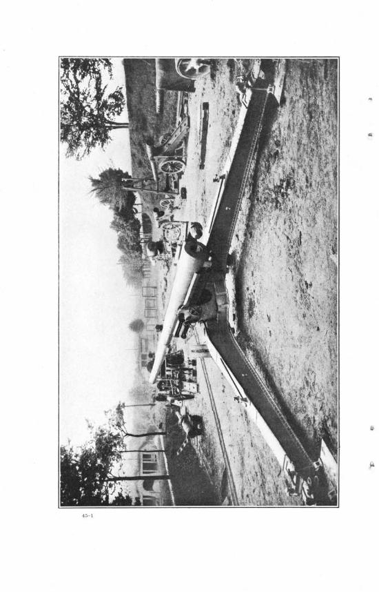
45
A report is made through proper channels to the mobile repair shop. I t is good practice to report all slight defects as soon as possible to the mobile repair shop. By so doing, in most cases, greater damages and more difficult repairs may be avoided.
ARTICLE 5.
Testing the Lines of Sight and Sighting Instruments.
132. I t is most important to verify the lines of sight, as the accuracy of the gun depends entirely on the correct adjustment of these lines.
A bad assembling, an occasional accident, or poor upkeep will produce errors which will destroy the calibration of the guns of a battery, or even cause a gun to give different results when sighted
( under different conditions. 133. This operation does not present any difficulty,, but must be
done with great care and accuracy, and must be performed frequently, especially when observations made in firing cause suspicions of bad adjustment. The gunner must be trained to perform this operation, but it must be done only in the presence of an officer.
. 134. The operation consists of the following: 1. See that the bubble of the elevation level is centered when the
gun is horizontal, the elevatibn drum and micrometer are at zero, and the bubble of the transverse level is centered.
2. See that the plane of sight is parallel to the axis of the bore when the deflection micrometer and limb are at zero, and the bubble of the cross level is centered.
The operation is performed as follows, the gun being on nearly level ground:
A. Elevation.
135. Set the elevation drum and micrometer at zero and center the bubble of the cross level. Set the axis of the bore horizontal; by construction the quadrant seats on the breech ring are parallel to the axis of the bore. I t is, consequently, sufficient to set these horizontal by means of a calibrated quadrant. See if the bubble of the elevation level is centered. If it is not, center it by operating the elevation micrometer. Note the reading of the elevation micrometer, which is the error in elevation of the sight. When firing, the angle of elevation, as given by the battery commander, must be corrected by the angle just determined. This error must not exceed eight minutes.
136. NOTE.—Calibrating a quadrant: 1. Set the quadrant at zero and place it on the breech ring seats.
Center the bubble by operating the elevating handwheel. 2. Turn the quadrant end for end. If the bubble remains cen
tered the level is correct. If not, center the bubble by moving the
46
level holder of the quadrant. Read the angle, which is double the error of the quadrant. To set the gun level with this quadrant it will he necessary to set the quadrant at half the angle found and then to center the bubble.
B. Direction.
137. Place at the muzzle two cross threads on the indices marked on the face of the muzzle and fasten them in position with wax or heavy grease. The breech being elosed, the line of sight marked by the point of intersection of the cross threads and the vent of the breechblock corresponds to the axis of the bore. Lay the gun by means of this line of sight on an aiming point, preferably at medium range. If the aiming point be close, parallax must be taken into consideration.
The bubbles of both levels being centered, and the limb at zero, bring the line of sight on the aiming point by turning the collimator counterclockwise, and record the deflection (which for perfect adjustment would be zero).
Eepeat by turning the collimator clockwise, and again record the deflection.
According to French practice the difference between the two deflections obtained must not exceed 4 decigrades, and both deflections must lie between 97 and 3.
Caution.—In getting each of these deflections the motion of the micrometer drum must be in one direction only. If the line of sight is brought past the aiming point, begin over again.
138. Any sight that does not fulfill the above conditions is tested on another gun. If it does not give a satisfactory result it is sent to the mobile repair shop. Any gun which does not prove satisfactory with one sight is tested with a second, and if necessary with a third. If none proves satisfactory, the sight bracket must be considered as out of adjustment, and a report of the fact made to the mobile repair shop.
CHAPTER IV.
GENERAL INFORMATION.
ARTICLE 1.
Painting Artillery Matgriel.
139. The paint issued for this purpose is ready for use on both wood and metal parts. If the paint is too thick, turpentine should be used as a thinner, but not to a greater extent than 2 per cent by volume.
All steel and iron nonbearing surfaces, including that portion of the underside of the gun between the gibs, will be painted. Wearing and bearing surfaces must not be painted.
47
All parts to be painted should be free from dirt and grease. They may be washed in a liquid made by dissolving one-half pound of sal ammoniac, in eight quarts of warm water/ then rinsed in clean water and wiped thoroughly dry.
Where the materiel is in fair condition and only marred in spots, the marred places should be primed with paint, second coat, and permitted to dry, then the whole surface should be sandpapered with No. 1J sandpaper, and a coat of paint applied and allowed to dry thoroughly before use.
Where the materiel is in bad condition all parts should be thoroughly sandpapered with No. 2 | sandpaper, be given a coat of paint, and permitted to dry for at least 24 hours. Then sandpaper with No. 00 sandpaper, apply a finishing coat, and permit the parts to dry thoroughly before use.
140. After repeated painting the paint may become so thick as to scale off in places or give an unsightly appearance. I t may then be removed for repainting as follows:
Dissolve 1 pound of concentrated lye, powdered form, in 6 pints of hot water and slake in enough lime to give the solution the consistency of paint. Use the solution freshly mixed and apply to the parts, where paint is to be removed, with a brush or with waste tied to the end of a stick. When the solution begins to dry on the surface, use a scraper to remove the old paint and complete the cleaning of the surface with cloth and water. If one application is not sufficient to loosen the paint, apply a second coat. Before painting, wash the surface with sal ammoniac water, rinse with clean water, and then wipe thoroughly as described above.
AETIOLE 2.
Oils for Artillery Materiel.
141. For the service, cleaning, and preservation of this materiel the Ordnance Department issues hydroline or another special oil for the recoil mechanism, lubricating oil (or engine oil No. 1), clock oil, sperm oil, neat's-foot oil, light slushing oil, and kerosene. Each of these is suited for the particular purpose for which it is issued, as stated below, and care should be taken that it is not used for other purposes.
142. The hydroline or special recoil mechanism oil is for use in the interior of the recoil and counter-recoil mechanisms and for no other purpose.
143. The lubricating oil (or engine oil No. 1), will be used exclusively in all oil holes of the materiel, and in lubricating such parts as breechblocks and threads of breech recesses.
144. Clock oil should be used on the moving parts of the sight and of all fire-control instruments. I t should be applied by drop-
48
ping from the end of the dropper attached to the end of the cork. Only a few drops of clock oil are required for the lubrication. Too much will destroy the efficiency of optical instruments.
145. The sperm oil is a lighter lubricant than the engine oil No. 1, and may be used on the gears of sights, fuse setters, and similar parts. Engine oil No. 1 may also be used on such parts.
146. Kerosene is used by the Ordnance Department for cleaning-purposes and for lanterns in the field. Kerosene for general illuminating purposes is furnished by the Quartermaster's Department. Neat's-foot oil is used for the care and preservation of all leather equipment,
147. Light slushing oil is prescribed for use in the protection and preservation of all bright or unpainted surfaces of steel or iron on all parts of the equipment when the materiel is to remain unused for any considerable length of time. I ts use as a lubricant is forbidden. Before applying the slushing oil to any surface- the parts should be thoroughly cleaned, so as to be free from rust, water, kerosene, or lubricating oil, as their presence will ' cause rusting under the slushing oil. The slushing oil should then be applied in a thin, uniform coat, since this is all that is necessary to give good protection; except in very cold weather it can be applied by using a paint brush as when painting. In cold weather it should be applied by stippling—that is, lightly tapping the surface with the end of the sash tool, held with bristles perpendicular to the surface to be covered. I t can be applied to the bores of guns by means of the greasing sponge issued for the purpose. In cold weather it should be warmed before use for coating the bores of the guns. I t may readily be removed by the use of waste or burlap dipped in kerosene.
ARTICLE 3.
General Suggestions.
148. Strain the oil used in filling the recoil and counter-recoil cylinders through a fine, clean cloth, and be sure that the receptacles used in handling the oil are absolutely clean.
All unpainted surfaces should be kept clean and free from rust, but in no case is a polish permitted.
Do not strike any metal part directly with a hammer; interpose a buffer of wood or copper.
Frequently test the adjustment of the sights. Exercise special care in handling the sights. Be careful about exposing ammunition unnecessarily to the sun
or loading it into a warm gun before time for firing. If this is done erratic results may be expected.
Smokeless powder must not be used f or blank cartridges.
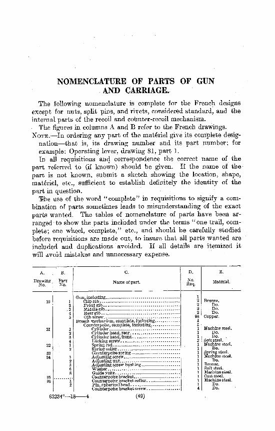
NOMENCLATURE OF PARTS OF GUN AND CARRIAGE.
The following nomenclature is complete for the French designs except for nuts, split pins, and rivets, considered standard, and the internal parts of the recoil and counter-recoil mechanism.
The figures in columns A and B refer to the French drawings. NOTE.—In ordering any part of the materiel give its complete desig
nation—that is, its drawing number and its part number; for example: Operating lever, drawing 81, part 1. In all requisitions and correspondence the correct name of the
part referred to (if known) should be given. If the name of the part is not known, submit a sketch showing the location, shape, materiel, etc., sufficient to establish definitely the identity of the part in question.
ISie use of the word "complete" in requisitions to signify a combination of parts sometimes leads to misunderstanding of the exact parts wanted. The tables of nomenclature of parts have been arranged to show the parts included under the terms "one trail, complete; one wheel, complete," etc., and should be carefully studied before requisitions are made out, to insure that all parts wanted are included and duplications avoided. If all details are itemized it will avoid mistakes and unnecessary expense.
A.
Drawing No.
10
31
32
33 34
35 36
B.
Part No.
1 2 3
" 4 5
1 2 3 4 1 2
1 2 3 6 8
1 2
c.
Name of part.
E.
Materiel.
63234°—18
Gun, including Clip gib • Front gib Middle gib Rear gib — Gib screw,
Breech mechanism, complete, including. Counterpoise, complete, including..
Cylinder Cylinder head, rear Cylinder head, front Locking screw Spring rod Spring collar Counterpoise spring Adjusting screw Adjusting nut Adjusting screw bushing Washer... ' . Guide yoke , Counterpoise bracket Counterpoise bracket collar Pin, spherical head. Counterpoise bracket screw
4 (49)
Bronze. Do. Do. Do.
Copper.
Machine steel. Do. Do. .
Soft steel. Machine steel.
Do. Spring steel. Machine steel.
Do. Bronze. Soft steel. Machine steel. Cast steel. Machine steel.
Do. Do.
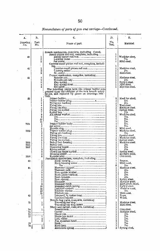
50
Nomenclature of parts of gun and carriage—Continued.
A.
Drawing No.
Part No.
C.
Name of part.
I>.
No. Req.
E.
Materiel.
40
51
52
7001
7002
7005 7006 7007
7008
63
64
65
Breech mechanism, complete, including—Oontd. Recoil piston rod nut, complete, including ,
Recoil piston rod nut * Locking collar , Set screw
Counter-recoil piston rod nut, complete, including
Counter-recoil piston rod nut Locking collar. Set screw
Primer mechanism, complete, including Spindle nut Spindle nut key Key spring Key spring rivet Set screw:
The following pieces form -the primer holder suppressed upon the addition of the new breech safety device, and replaced by pieces on drawings 7001-7002:
Primer holder Primer holder plug t Firing pin bushing Firing pin Firing pin stop Firing pin spring Spring key Adjusting washer
Do Do Do
Primer holder body Set screw Handle ring Primer holder plug Firing pin bushing Firing pin Firing pin stop Firing pin spring Safety lock housing Safety lock Operating finger Spring socket , . Operating finger spring Housing screw Spindle plug
Percussion mechanism, complete, including Rack housing ^ Rack-housing screw
Do Hammer support Hammer rack Racic-guide washer Rack-guide bushing Rack spindle Rack spring Hammer Hammer catch Hammer-catch spring Lanyard eyebolt Eyebolt washer E yebolt pin Lanyard, 9J inches long. . . . Lanyard handle.
Breech ring parts, complete, including: Traveling bar stop Traveling bar stop screw
Block and carrier, complete, including Breechblock Carrier Hinge pin. . . . Hinge pin collar Lock collar Pin, spherical head Rack... Rack lock Rack-lock spring
Machine steeL Do. <
Mild steel.
Machine steel. Do.
Mild steel.
Machine steel. Do.
Spring steel. Mild steel. Machine steel.
Machine steel. Do. Do.
Tool steel. Machine steel. Spring steel.
Do. Machine steel.
Do. Do. Do. Do. Do.
Mild steel. Machine steel.
Do. Special steel. Machine steel. Spring steel. Machine steel.
Do. Do. Do.
Spring steel. Machine steel. Gun steel.
Bronze. Mild steel.
Do. Machine steel.
Do. Do. Do. Do.
Spring steel. Machine steel. High-grade steel. Spring steel. Machine steel.
Do. Mild steel. Rope. Wood.
Machine steel. Mild steel.
Gun steel. Machine steel.
Do. Do. Do. Do. Do. Do.
Spring steel.
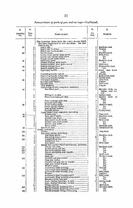
51
Nomenclature of-parts of gun and carriage—Continued.
Drawing No.
Part No. Name of part. No.
Eeq.
E.
Matenel.
85
87
94
100.
101
102
120 121 140 141
143
146
115
159
160
The following pieces form the safety device which has been suppressed in new materiels. See footnote to par. 15.
Safety pin Safety pin bushing Safety pin bushing nut Carrier latch . . Lower front carrier latch screw Lower rear carrier latch screw Upper carrier latch screw Operating lever : Breech-locking lever guide Breech-locking lever guide screw Breech-locking lever Breech-locking lever pin Operating handle
Operating-handle socket Operating-handle socket nut Operating-handle spring Obturator spuidle Spindle plug washer Spindle plug vent bushing Obturating device, complete, including.
Gas check pad
Filling-in washer Front external split ring.
Rear external split ring Internal split ring Front spring collar.. Front spring washer Rear spring washer Spindle spring
Open breech stop, complete, including Breech stop Back latch catch Breech stop plate Back latch catch screw Breech stop plate screw Breech stop screw. Shear collar...
Quadrant seat Cradle, including
Cradle .-. Elevating sector, including
Elevating sector Elevating sector screw Longitudinal key Transverse key Key screw
Recoil and counter-recoil mechanism, including Piston rod yoke Recoil piston rod key Recoil regulating arm Recoil regulating arm spindle Washer Slide pin Counter-rod gear sector Cam gear sector Counter-rod gear sector washer Cam gear sector washer Washer screw Automatic filler housing Automatic filler housing cover Automatic filler housing plug Washer Automatic filler housing screw Automatic filler housing cover screw Housing cover bolt nut Lock washer (Grower), 16 mm Lock washer (Grower), 12 mm Thong eyebolt Recoil cylinder draining sleeve Recoil cylinder draining connection Recoil cylinder filling orifice plug
Machine steel. Bronze.
Do. Machine steel. Mild steel.
Do. Do.
Machine steel. Do.
Mild steel. High-grade steel.
Do. Steel, case hard
ened. Bronze. High-grade steel. Spring steel. Gun steel. Copper. Gun steel. Copper.
Metallic cloth, asbestos, and tallow.
Special steel. Special steel or
brass. Do Do.
Machine steel. Do. Do.
Spring steel.
Cast steel. Machine steel. Bronze. Mild steel.
Do. Do.
Machine steel. German silver.
Gun steel.
Machine steel. Do. Do. Do.
Mild steel.
Machine steel. Do. Do. Do.
Mild steel. Machine steel.
Do. Do. Do. Do. Do.
Bronze. Do.
Mild steel. Leather.' Mild steel.
Do. Do.
Spring steel. Do.
Mild steel. Machine steel.
Do. Do.
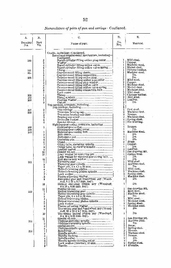
52
Nomenclature of parts of gun and carriage—Continued.
Drawing No.
C.
Name of part.
E.
Materiel.
160
161 205
206
204 172 208
301 302
308 309 310
311
312
313
314
10
Cradle, including—Continued. Recoil and counter-recoil mechanism, including—
Continued. Recoil cylinder filling orifice plug collar. . . . . Washer Recoil cylinder filling orifice valve Recoil cylinder filling orifice valve spring— Thong Counter-recoil filling sleeve Counter-recoil filling connection Counter-recoil filling orifice plug Counter-recoil filling orifice plug collar Counter-recoil filling plug washer Counter-recoil filling orifice valve Counter-recoil filling orifice valve spring.;... Counter-recoil filling connection lock Lock screw Thong Thong eyebolt: Packing washer Gasket
Top carriage, complete, including Top carriage, including
Top carriage Trunnion bearing cap Trunnion bearing cap liner Bearing cap screw Belleville washer Special oil cup
Sighting-gear casing, complete, including . Sighting-gear casing Sighting-gear casing cover Sighting-gear casing bo l t . . . : Bolt sleeve Bolt-sleeve nut Centering pin Gland Oil ing tube, elevating spindle Oiling tube, traversing spindle Leather gasket Special oil cup Lock washer for centering pin Lock washer for sighting gear-casing bol t . . . Bolt sleeve lock washer Elevating gear Elevating gear spindle Taper pin, 5 x 4.5 x 50 mm Helical elevating pinion...' Helical elevating pinion spindle Lock washer Pinion adjusting washer Elevating gear and hand wheel key (Wood
ruff, 6 x 22 x 9.7 mm. key). Helical elevating pinion key (Woodruff,
8 x 19 x 8.55 mm. key). Special oil cup Helical traversing gear Helical traversing gear spindle Taper pin, 5 x 5.5 x 50 mm Helical traversing pinion Helical traversing pinion spindle Lock washer Pinion ad'usting washer Traversing gear and handwheel key (Wood
ruff, 62 x 22 x 9.7 mm. key). Traversing helical pinion key (Woodruff,
8 x 19 x 8.55 mm. key). Special oil cup Oblique elevating spindle Oblique traversing spindle Spring socket Oblique spindle spring Handwheel Handle spindle Handle bushing Spindle collar Handle spindle riveting collar Lock washer (Grower), 10 mm H a n d l e . . . . . . . . . . . . . . . . . . . . . . . . . . . . . . . . . . . .
1 1 1 1 1 1 1 2 2 2 2 2 1 2 2 2 2 2 1 1 1 2 2 2 2 2 1 1 1 3 3 3 1 2 1 1 2 2 1 4 3 1 1 1 1 1 2 1 2
1
1 1 1 1 1 1 2 1 2
1
1 1 1 2 2 2 2 ?, 2 2 2 2
Mild steel. Copper. Machine steel. Nickel steel. Chrome leather. Machine steel.
Do. Do.
Mild steel. Copper. Machine steel. Nickel steel. Machine steel. Mild steel. Chrome leather. Mild steel. Leather.
Do.
Cast steel. Machine steel. Bronze. Machine steel. Spring steel. See drawing.
Bronze. Do.
Machine steel. Do. Do. Do.
Brass. Copper.
Leather. See drawing 801. Spring steel.
Do. Do.
Mild steel. Machine steel.
Do. Mild steel. Machine steel. Spring steel. Machine steel.
Do.
Do.
See drawing 801. Mild steel. Machine steel.
Do. Mild steel. Machine steel. Spring steel. Machine steel.
Do.
Do.
See drawing 801 Machine steel.
Do. Brass. Spring steel. Bronze. Machine steel. Bronze.
Do. Do.
Spring steel. Ebonite,
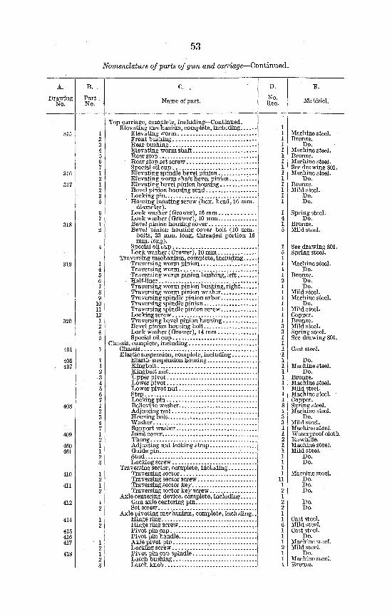
53
Nomenclature of parts of gun and carriage—Continued.
A.
Drawing No. Name of part.
E.
Materiel.
316
317
318
320
406 407
408
409
460 461
410
411
412
414
415 416 417
418
Top carriage, complete, including—Continued. Elevating mechanism, complete, including
Elevating worm Front bushing Rear bushing Elevating worm shaft Rear stop Rear stop set screw Special oil cup Elevating spindle bevel pinion Elevating worm shaft bevel pinion I . . Elevating bevel pinion housing Bevel pinion housing stud Looting pin Housing locating screw (hex. head, 16 mm.
diameter). Lock washer (Grower), 16 mm Lock washer (Grower), 10 mm Bevel pinion housing cover Bevel pinion housing cover bolt (10 mm.
bolts, 33 mm. long, threaded portion 16 mm. long).
Special oil cup Lock washer (Grower), 10 mm
Traversing mechanism, complete, including Traversing worm pinion Traversing worm Traversing worm pinion bushing, l e f t . . . . . . Half-liner Traversing worm pinion bushing, right Traversing worm pinion washer Traversing spindle pinion arbor Traversing spindle pinion Traversing spindle pinion screw Locking screw Traversing bevel pinion housing Bevel pinion housing bolt Lock washer (Grower), 14 mm Special oil cup
Chassis, complete, including Chassis Elastic suspension, complete, including
E lastic suspension housing Kingbolt Kingbolt nu t . . Upper pivot Lower pivot Lower pivot nut Step , Locking pin Belleville washer Adjusting nut Housing bolt Washer Support washer Joint cover Thong Adjusting nut locking strap Guide pin Stud Locking screw
Traversing sector, complete, including Traversing sector Traversing sector screw Traversing sector key. Traversing sector key screw
Axle centering device, complete, including Gun axle centering pin Set screw
Axle pivoting mechanism, complete, including. Hinge ring Hinge ring screw Pivot pin cap , '. Pivot pin handle .' Axle pivot pin Locking screw ' Pivot pin cap spindle Latch bushing Latch knob
Machine steel. Bronze.
Do. Machine steel. Bronze. Machine steel. See drawing 8( Machine steel.
Do. Bronze. Mild steel.
Do. Do.
Spring steel. Do.
Bronze. Mild steel.
See drawing 801. Spring steel.
Machine steel. Do.
Bronze. Do. Do.
Mild steel. Machine steel.
Do. Mild steel. Copper. Bronze. Mild steel. Spring steel. See drawing 801.
Cast steel.
Do. Machine steel.
Do. Bronze. Machine steel. Mild steel. Machine steel. Copper. Spring steel. Machine steel.
Do. Mild steel. Machine steel. Waterproof cloth. Rawhide. Machine steel. Mild steel.
Do. Do.
Machine steel. Do. Do. Do.
Do. Do.
Cast steel. Mild steel. Cast steel.
Do. Machine steel. Mild steel.
Do. Machine steel. Bronze.
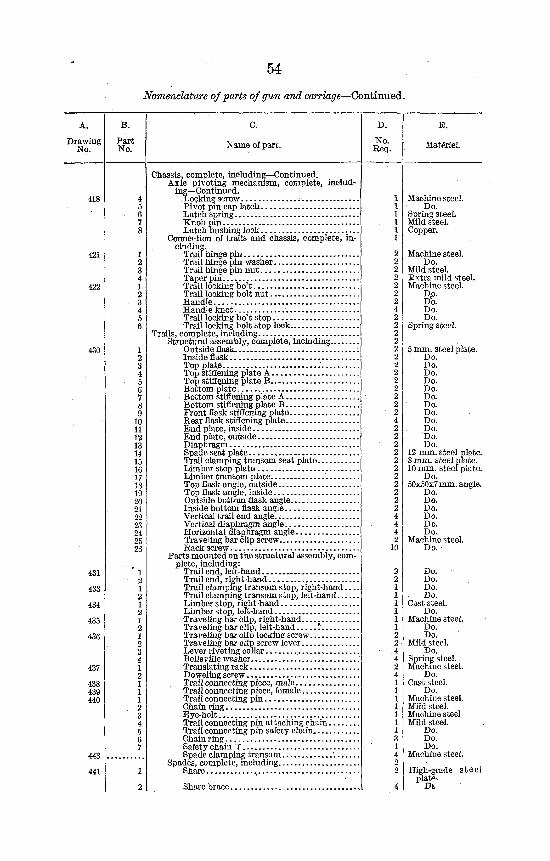
54 Nomenclature of parts of gun and carriage—Continued.
A.
Drawing No. Name of part.
E.
Materiel.
418
421
422
430
431
433
434
435
436
437
438 439 440
443
441
1 2 3 4 1 2 3 4 5 6
1 2 3 4 5 6 7 8 9
10 11 12 13 14 15 16 17 18 19 20 21 22 23 24 25 26
' 1 2 1 2 1 2 1 2 1 2 3 4 1 2 1 1 1
. 2 3 4 5 6 7
1
Chassis, complete, including—Continued. Axle pivoting mechanism, complete, includ
ing—Continued. Locking screw Rivotpincap latch Latch spring Knob pin Latch bushing lock
Connection of trails and chassis, complete, including.
Trail hinge pin Trail hinge pin washer Trail hinge pin nut Taper pin Trail locking bo11 Trail locking bolt nut Handle Handle knot Trail locking bo't stop Trail locking bolt stop lock....
Trails, complete, including Structural assembly, complete, including
Outside flask..'. Inside flask Top plate - .' Top stiffening plate A Top stiffening plate B , Bottom plate Bottom stiffening plate A Bottom stiffening plate B . . . Front flask stiffening plate. Rear flask stiffening plate End plate, inside End plate, outside Diaphragm Spade seat plate , Trail clamping transom seat plate Limber stop plate Limber transom plate Top flask angle, outside. Top flask angle, inside Outside bottom flask angle Inside bottom flask angle Vertical trail end angle.. Vertical diaphragm angle Horizontal diaphragm angle Traveling bar clip screw Rack screw
Parts mounted on the structural assembly, complete, including:
Trailend, left-hand Trail end, right-hand Trail clamping transom stop, right-hand... Trail clamping transom stop, left-hand Limber stop, right-hand Limber stop, left-hand Traveling bar clip, right-hand Traveling har clip, leit-hand ! Traveling bar clip locking screw Traveling bar clip screw lever Lever riveting collar , Belleville washer Translating rack Doweling screw Trail connecting piece, male Trail connecting piece, female Trail connecting pin Chain ring Eye-bolt Trail connecting pin attaching chain. . . Trail connecting pin safety chain Chain ring Safety chain T Spade clamping transom '...-...
Spades, complete, including Share .,
Share brace
1 1 1 1 1 1
2 2 2 2 2 2 2 4 2 2 2 2 2 2 2 2 2 2 2 2 2 4 2 2 2 2 2 2 2 2 2 2 2 4 4 4 2
10
2 2
2 2 4 4 2 4 1 1 1 1 1 1 1 3 1 4 2 2
4
Machine steel. Do.
Spring steel. Mild steel. Copper.
Machine steel. Do.
Mild steel. Extra mild steel. Machine steel.
D,o. Do. Do. Do.
Spring steel.
5 mm. steel plate. Do. Do. Do. Do. Do. Do. Do. Do. Do. Do. Do. Do.
12 mm. steel plate. 8 mm. steel plate. 10 mm. steel plate.
Do. 50x50x7 mm. angle.
Do. Do. Do. Do. Do. Do.
Machine steel. Do. •
Do. Do. Do. Do.
Cast steel. Do.
Machine steel. Do. Do.
Mild steel. Do.
Spring steel. Machine steel.
Do. Cast steel.
Do. Machine steel. Mild steel. Machine steel Mild steel.
Do. Do. Do.
Machine steel.
High-grade steel plat*-
Dt
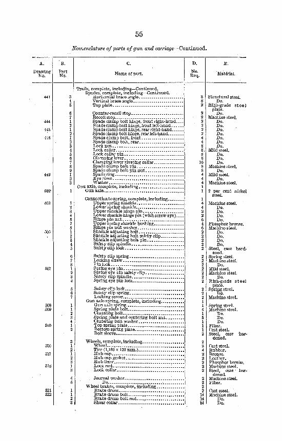
55
Nomenclature of farts of gun and carriage—Continued.
A.
Drawing No.
C.
Name of part.
E.
Materiel.
444
445
446
449
502
503
505
507
508 509
516
517
518
521 522
Trails, complete, including—Continued. Spades, complete, including—Continued.
Horizontal brace angle Vertical brace angle Top plate
Counter-recoil stop Recoil stop Spade clamp bolt hinge, front right-hand. Spade clamp bolt hinge, front left-hand... Spade clamp bolt hinge, rear right-hand... Spade clamp bolt hinge, rear left-hand Spade clamp bolt, front Spade clamp bolt, rear Lock nut ^ Lock collar Lock collar pin Clamping lever Clamping lever riveting collar Spade clamp bolt pin Spade clamp bolt pin nut Spade ring Eye rivet Washer
Gun axle, complete, including Gun axle
Connection to spring, complete, including. Upper spring shackle Lower spring shackle Upper shackle hinge pin Lower shackle hinge pin (with screw e Hinge pin nut •. Upper spring shackle bushing Hinge pin nut washer Shackle adjusting bolt Shackle adjusting bolt safety clip Shackle adjusting bolt pin Safety clip spindle Safety clip lock
Safety clip spring , Locking screw Pin lock , Spring eye pin Spring eye pin safety clip. Safety clip spindle Spring eye pin lock..
Safety clip lock Safety clip spring Locking screw
Gun axle spring, complete, including.... Gun axle spring Spring plate bolt Centering bolt Spring plate and centering bolt nut . Centering bolt washer Top spring plate Bottom spring plate Bolt sleeve
Wheels, complete, including. Wheel Tire (1,160x120 mm.) . . . Hub cap Hub cap gasket Hub liner Lock nut -.. Lock collar
Journal washer Do
Wheel brakes, complete, including. Brake drum Brake drum bolt Brake dram bolt nut Shear collar
16
Structural steel. Do.
High-grade s t e e l plate.
Do. Machine steel.
Do. Do. Do. Do. Do. Do. Do.
Mild steel. Do. Do. Do.
Machine steel. Do.
Mild steel. Do.
Machine steel.
2 per cent nickel steel.
Machine steel. Do. Do. Do. Do.
Phosphor bronze. Machine steel.
Do. Do. Do. Do.
Steel, case hardened.
Spring steel. Machine steel.
Do. Mild steel. Machine steel.
Do. High-grade s tee l
plate. Spring steel.
Do. Machine steel.
Spring steel. Machine steel.
Do. Do. Do.
Fiber. Cast steel. Steel, case
dened. har-
Cast steel. Rubber. Bronze. Leather. Phosphor bronze. Machine steel. Steel, case har
dened. Machine steel. Fiber.
Cast steel. Machine steel.
Do. Do.
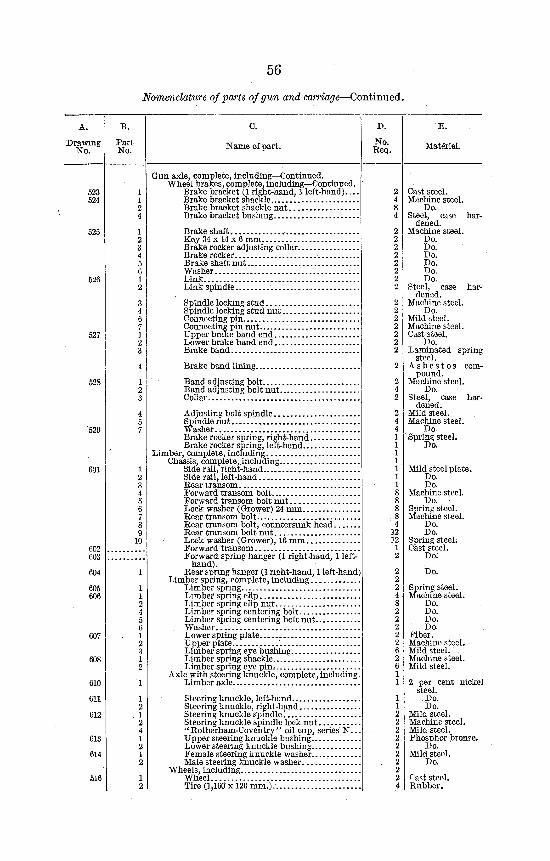
56
Nomenclature of parts of gun and carriage—Continued.
A.
Drawing No.
C.
Name of Dart.
E.
Materiel.
523 524
525
527
528
529
601
fin? 603
604
605 606
607
608
610
611
612
613
614
516
1 2 3 4 5 6 7 8 9 10
1
1 1 2 4 5 6 1 2
1 2
1
1 2 1 2 4 1 2 1 2
1 2
Gun axle, complete, including—Continued. Wheel brakes, complete, including—Continued.
Brake bracket (1 right-band, 1 left-hand)... Brake bracket shackle Brake bracket shackle nut Brake bracket bushing
Brake shaft Key 34 x 14 x 6 mm Brake rocker adjusting collar. Brake rocker Brake shaft nut Washer Link Link spindle
Spindle locking stud Spindle locking stud nut . Connecting pin Connecting pin nut Upper brake band end. . . Lower brake band end. . . Brake band
Brake band lining.
Band adjusting bolt Band adjusting bolt nut. Collar
Adjusting bolt spindle Spindle nut Washer Brake rocker spring, right-hand Brake rocker spring, left-hand
Limber, complete, including Chassis, complete,.including
Side rail, right-hand Side rail, left-hand Rear transom Forward transom bolt Forward transom bolt nut Lock washer (Grower) 24 mm , Rear transom bolt. Rear transom bolt, countersunk head Rear transom bolt nut , Lock washer (Grower), 16 mm Forward transom Forward spring hanger (1 right-hand, 1 left-
hand). Rear spring hanger (1 right-hand, 1 left-hand)
Limber spring, complete, including Limber spring Limber spring clip Limber spring clip nut Limber spring centering bolt Limber spring centering bolt nut Washer Lowerspring plate Upper plate Limber spring eve bushing Limber spring shackle Limber spring eye pinr.
Axle with steering knuckle, complete, including Limber axle
Steering knuckle, left-hand. Steering knuckle, right-hand Steering knuckle spindle'. Steering knuckle spindle lock nut "Rotherham-Coventry" oil cup, series N. Upper steering knuckle bushing Lower steering knuckle bushing Female steering knuckle washer Male steering knuckle washer
Wheels, including Wheel Tire (1,160x120 mm.).
Cast steel. Machine steel.
Do. Steel, case har
dened. Machine steel.
Do. Do. Do. Do. Do. Do.
Steel, case hardened.
Machine steel. Do.
Mild steel. Machine steel. Cast steel.
Do. Laminated spring
steel. A s b e s t o s com
pound. Machine steel.
Do. Steel, case har
dened. Mild steel. Machine steel.
Do. Spring steel.
Do.
Mild steel plate. Do. Do.
Machine steel. Do.
Spring steel. Machine steel.
Do. Do.
Spring steel. Cast steel.
Do.
Do.
Spring steel. Machine steel.
Do. Do. Do. Do.
Fiber. Machine steel. Mild steel.' Machine steel. Mild steel.
2 per cent niekei steel.
Do. Do.
Mild steel. Machine steel. Mild steel. Phosphor bronze.
Do. Mild steel.
Do.
Cast steel. Rubber.
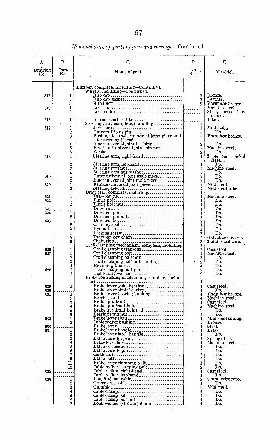
57
Nomenclature of parts of gun and carriage—Continued.
Drawing No.
B.
Part No.
C.
Name of part. No. Rec-
E.
Materiel.
517
518
616
617
618
619
620
621 622
623 624
625
626 627
628
629 630 631
632
633 634
635
636
Limber, complete, including—Continued. Wheels, including—Continued.
Hub cap ,. Hub cap gasket .'. Hub liner L ock nut Lock collar
Journal washer, fiber Steering gear, complete, including
Pivot pin Universal joint pin Bushing for male universal joint piece and
for steering tie-rod. Inner universal joint bushing Pivot and universal joint pin nut Washer Steering arm, right-hand
Steering arm, left-hand Steering arm nut. Steering arm nut washer Outer universal joint male piece Inner universal j oint male piece Female universal joint piece Steering tie-rod
Draft gear, complete, including Drawbar tie . Pintle bolt Pintle bolt nut Drawbar Drawbar pin Drawbar pin nut Drawbar key Chain eyebolt Eyeboltnut -. Locking serew Drawbar key chain Chain ring
Trail clamping mechanism, complete, including. Trail clamping transom Trail clamping bolt Trail clamping bolt nut Trail clamping bolt nut handle Retaining knob Trail clamping bolt pin Tightening washer
Brake controlling machanism, complete, including.
Brake lever yoke bearing Brake ip.ver shaft bearing Brake lever bearing bushing. Bearing stud Brake quadrant Brake quadrant bolt Brake quadrant bolt nut Bearing stud nut Brake lever shaft Cable rocker bushing Brake lever Brake lever handle Brake lever latch handle Latch handle spring Brake lever latch Latch connection Latch handle pin Castle nut Latch bolt Brake lever clamping bolt Cable rocker clamping bolt . . . Cable rocker, right-hand Cable rocker, left-hand Longitudinal cable Transverse cable Thimble Cable clamp Cable clamp bolt Cable clamp bolt nut Lock washer (Grower) 6 mm.
Bronze. Leather. Phosphor bronze. Machine steel. Steel, case har
dened. Fiber.
Mild steel. Do.
Phosphor bronze.
Do. Machine steel.
Do. 2 per cent nickel
steel. , Do.
Machine steel. Do. Do. Do.
Mild steel. Mild steel tube.
Machine steel. Do. Do. Do. Do. Do. Do. Do. Do. Do.
Galvanized chain. 3 mm. steel wire.
Cast steel. Machine steel.
Do. Do. Do. Do. Do.
Cast steel. Do.
Phosnhor bronze. Machine steel. Cast steeL Machine steel.
Do. Do.
Mild steel tubing. Bronze. Steel. Brass.
Do. Spring steel. Machine steel.
Do. Do. Do. Do. Do. Do.
Cast steel. Do.
8 mm. wire rope. Do.
Mild steel. Do. Do. Do. Do.
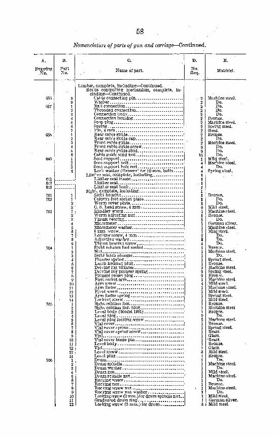
58
Nomenclature of parts of gun and carriage—Continued.
A.
Drawing No.
Part No.
C.
Name of part. No. Req.
E.
Materiel.
636
637
63b
640
641 642 643
701 702
703
704
705
706
Limber, complete, including—Continued. Brake controlling mechanism, complete, in
cluding—Continued. Cable connecting pin. Wash er , Ball connection Threaded connection. Connection body Connection housing... . < Stop plug Spring.. , , Pin, 4 mm _. Rear cable guide Rear cable guide cap Front cable guide Front cable guide screw Rear cable guide stud Cable guide stud nut Seat su pport Seat support bolt Seat support bolt nut Lock washer (Grower) for 10 mm. bolts
Limber seat, complete, including Limber seat frame Limber seat Limber seat back
Sightj complete, including Sight housing Column foot socket plate Worm cover plate C. S. head screw, 4 mm Hindley worm Worm adjusting nut Thrust bearing Micrometer Micrometer washer 6 mm. screw Locking screw, 4 mm Adjusting washer Thrust bearing screw .' Sight column foot socket Nut Sischt latch plunger Plunger spring Latch housing plug Driving lug plunder Driving lug plunger spring Plunger recess plug Foot socket arm Arm screw... . Arm finger Pivot screw.. . . . Arm fingersprlng Locking screw Sisiht column foot Sight column foot plug Level body (Model 1901)..-. Level plug Level plug locking screw ,. Vial cover Vial cover spring Vial cover spring screw Vial Vial cover hinge pin Level body Vial Level screw. Level plug Drum Drum spindle Drum washer Drum nut Drum spindle nut Rocking screw . Rocking nut Rocking screw nut •Rocking screw nut washer Lockingserew (2 mm.) ror drum spindle nut . Graduated drum ring Locking screw (2 mm.) for drum
Machine steel. Do. Do. Do. Do.
Bronze. Machine steel. Spring steel. Steel. Bronze.
Do. Machine steel.
Do. Do. Do.
Mild steel. Machine steel.
Do. Spring steel.
Bronze. Do. Do.
Mild steel. Machine steel. Bronze.
Do. German silver. Machine steel. Mild steel.
Do. Do. Do.
Bronze. Machine steel.
Do. Spring steel. Bronze. Machine steel. Spring steel. Bron/.e. Machine steel. Mild steel. Machine steel. Mild steel. Spring steel. Mild steel. Bronze. Machine steel. Bronze.
Do. Machine steel. Bronze. Spring steeL Brass. Glass.
4Brass. Bronze. Glass. Mild steel. Bronze.
Do. Machine steel.
Do. Mild steel. Machine steel.
Do. Bronze. Machine steel.
Do. Mild steel. German silver. Mild steel.
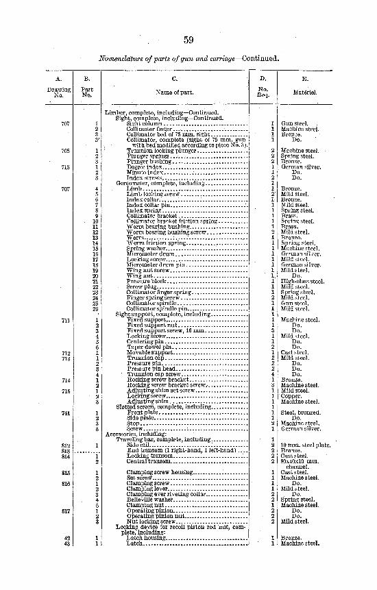
59
Nomenclature of parts of gun and carriage—Continued.
A.
Drawing No.
707
708
718
707
711
712 713
714
715
741
812 813 814
815
816
817
42 43
B.
Part No.
1 2 8 3'
1 2 3 1 2 3
4 5 6 7 8 £
• 10 11 12 13 14 15 16 17 18 19 20 21 22 23 24 25 26
1 2 3 4 5 6 1 1 2 3 4 1 2 1
• 2 3
1 2 3 5
1
1 2
1 2 1 2 3 4 5 1 2 3
1 1
c.
Name of part.
E.
Materiel.
Limber, complete, including—Continued. Sight, complete, including—Continued.
Sight column Collimator finger ,..• Collimator bed of 75 mm. sight Collimator, complete (sight of 75 mm. gun
, with bed modified according to piece No. 3) Trunnion locking plunger Plunger springs... Plunger bushing Degree index Minute index Index screws
Goniometer, complete, including Limb , Limb locking screw Index collar . Index collar pin Tndex spring Collimator bracket Collimator bracket friction spring Worm bearing bushing Worm bearing bushing screw Worm Worm friction spring Spring washer , Micrometer drum Locking screw Micrometer drum pin Wing nut screw Wing nut Pressure block Screw plug Collimator finger spring Finger spring screw Collimator spindle Collimator spindle pin
Sight support, complete, including Fixed support Fixed support nut Fixed support screw, 16 mm , Locking screw Centering pin Taper dowel pin Movable support Trunnion cap '. Pressure pin Pressure pin head
' Trunnion cap screw Rocking screw bracket Rocking screw bracket screw.-. Adjusting shim set screw Locking screw Adjusting shim
Slotted screen, complete, including Front plate Side plate Stop , Screw ;
Accessories, including: Traveling bar, complete, including ,
Side rail End transom (1 right-hand, 1 left-hand) Locking transom '.. Central transom ,
Clamping screw housing , Set screw Clamping screw , Clamping lever Clamping ever riveting collar. Belleville washer Clamping nut Operating pinion , Operating pinion nut Nut locking screw
Locking device for recoil piston rod hut, complete, including:
Latch housing Latch
Gun steel. Machine steel. Bronze.
Do.
Machine steel. Spring steel. Bronze. German silver.
Do. Do.
Bronze. Mild steel. Bronze. Wild steel. Spring steel. Brass. Spring steel. Brass. Mild steel. Bronze. Spring steel. Machine steel. German silver. Mild steel. German silver. Mild steel.
Do. High-class steel. Mild steel. Spring steel. Mild steel. Gun steel. Mild steel.
Machine steel. Do. Do.
Mild steel. Do. Do.
Cast steel. Mild steel.
Do. Do. Do.
Bronze. Machine steel. Mild steel. Copper. Machine steel.
Steel, bronzed. Do.
Machine steel. German silver.
10 mm. steel plate. Bronze. Cast steel. 80x40x10 mm.
channel., Cast steel. Machine steel.
Do. Mild steel.
Do. Spring steel. Machine steel.
Do. Do.
Mild steel.
Bronze. Machine steel.
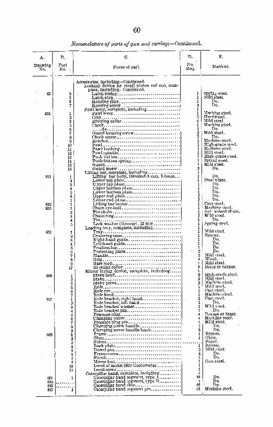
60
Nomenclature of parts of gun and carriage—Continued.
Drawing No.
Part No. Name of part. No.
Req.
E.
Matenel.
821
831
832 833
851
867
887
Accessories, including—Continued. Locking device for recoil piston rod nut, com
plete, including—Continued. Latch spring Latch stop Housing plug Housing screw..
Pawl lever, complete, including Pawl lever Grip Riveting collar Cheek
do . . . : . . Guard locating screw Cheek screw Ratchet Pawl Pawl bushing -Pawl spindle Push button Push-button spring Guard Guard screw
Lifting bar, complete, including Lifting bar body, 180x82x6.9 mm. I-beam... Lower top plate Upper top plate "Upper bottom plate Lower bottom plate Upper end plate Lower end plate Lifting bar center Chain eye-bolt Pin chain Chain ring Pin Lock washer (Grower), 12 mm
Loading tray, complete, including Tray Centering cone : Right-hand guide Left-hand guide Position lug Protecting plate Handle Grip Base stop Riveting collar
Mirror laying device, complete, including.. Stake head Stake... Stake point Rule Rule eye Rule head Rule bracket, right hand Rule bracket, left hand Rule bracket washer Rule bracket pin Pressure plug Clamping screw Pressure plug pin Clamping screw handle Clamping screw handle knob Frame Glass Shims Back plate D owel pin Frame screw Shank Mirror foot Level of model 1903 Goniometer Level screw
Caterpillar band, complete, including Caterpillar band segment, type A Caterpillar band segment, type B Caterpillar band shoe Caterpillar band segment pin
Spring steel. Mild steel.
Do. Do.
Machine steel. Hardwood. Mild steel. Machine steel.
Do. Mild steel.
Do. Machine steel. High-grade steel. Machine steel. Mild steel. High-grade steel. Spring steel. Mild steel.
Do.
Do. Steel plate.
Do. Do. Do. Do. Do.
Cast steel. Machine steel.. Gal anized chain. Mild steel.
Do. Spring steel.
Mild steel. Bronze.
Do. Do. Do. Do.
Mild steel. Wood. Mild steel. Brass or copper.
High-grade steel. Mild steel. Machine steel. Mild steel. Cast steel. Machine steel. Cast steel.
Do. Mild steel.
Do. Bronze or brass. Machine steel. Mild steel.
Do. Do.
Bronze. Glass. Paper. Bronze. Mild steel.
Do. Do.
Cast steel.
Do. Do. Do.
Machine steel.
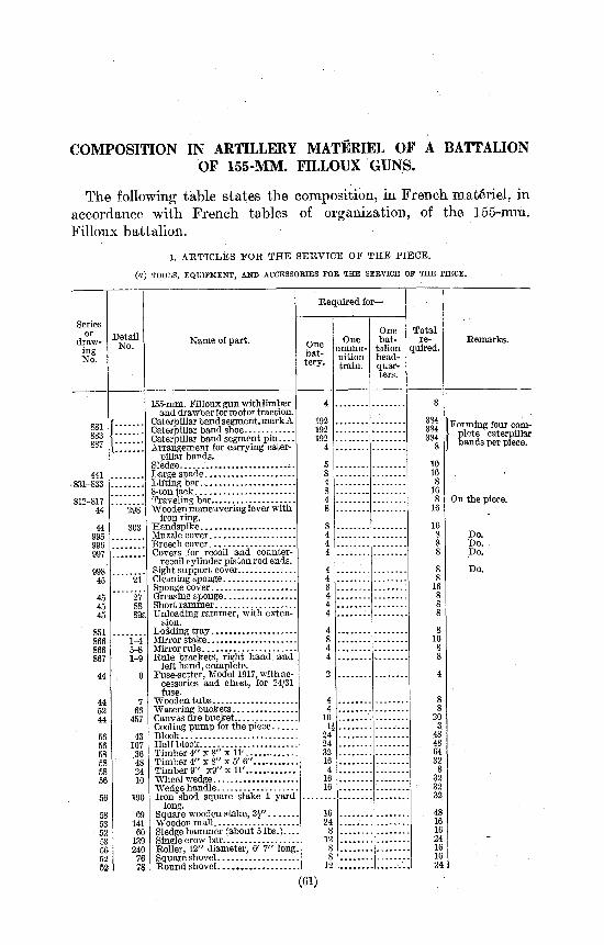
COMPOSITION IN ARTILLERY MATERIEL OF A BATTALION OF 155-MM. FILLOUX GUNS.
The following table states the composition, in French materiel, in accordance with French tables of organization, of the 155-mm. Filloux battalion.
1. ARTICLES FOR THE SERVICE OF THE PIECE.
(a) TOOLS, EQUIPMENT, AND ACCESSORIES FOE THE SERVICE OF THE PIECE.
Series or
drawing No.
Detail No.
Required for—
Name of part. One battery.
One ammunition train.
One bat
talion head-quarters.
Total re
quired. Remarks.
441 • 831-833
812-817 44
998 45
45 45 45
851 866 866 867
44
298
303
1-4 5-8 1-9
7 66
457
43 107 36
'48 24 10
190
141 60 139 240 76 78
155-mm. Filloux gun withlimber and drawbar for motor traction.
Caterpillar band segment.mark A Caterpillar band shoe Caterpillar band segment pin Arrangement for carrying cater
pillar bands.
Large spade Lifting bar 8-ton jack : Traveling bar Wooden maneuvering lever with
iron ring. Handspike Muzzle cover Breech cover Covers for recoil and counter-
recoil cylinder piston rod ends. Sight support cover Cleaning sponge Sponge cover. Greasing sponge Short rammer Unloading rammer, with exten
sion. Loading tray Mirror stake. . . Mirror rule Rule brackets, right hand and
left hand, complete. Fuse-setter, Model 1917, with ac
cessories and chest, for 24/31 fuse.
Wooden tubs Watering buckets Canvas fire bucket Cooling pump for the piece Block Half block Timber 4" x 8" x 11' Timber 4" x 8" x 5' 6" Timber 9" x9" x 11' Wheel wedge Wedge handle Iron shod square stake 1 yard
long. Square wooden stake, Z\" Wooden mall Sledge hammer (about 5 lbs.). . . Single crow bar. Roller, 12" diameter, 6' 7" long Square shovel Round shovel ,
192 192 192
4 10 1*
24 24 32 16 4
16 16
384 384 384
| Forming four complete caterpillar bands per piece.
16
On the piece.
Do. Do. Do.
Do.
(61)
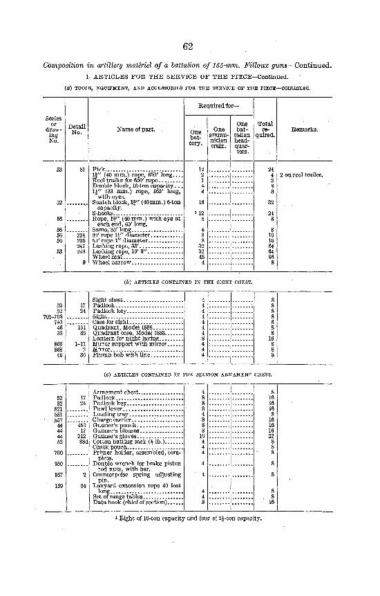
62
Composition in artillery maUriel of a battalion of 155-mm. Filloux guns—Continued. 1. ARTICLES FOR THE SERVICE OF THE PIECE—Continued.
(a) TOOLS, EQUIPMENT, AND ACCESSORIES FOE THE SERVICE OF THE PIECE—Continued.
Series or
drawing No.
53
52
56
56 56 56
53
Detail No.
81
234 235 247 248
9
Name of part.
Pick \f (40 mm.) rope, 650' long Reel trailer for 650' rope Double block, 10-ton capacity. . . \\" (33 mm.) rope, 165' long,
with eyes. Snatch block, If" (40mm.) 6-ton
capacity. S-hooks Rope, If" (40 mm.) with eye at
each end, 65' long. Same, 35' long 80' rope \\" diameter 50' rope 1" diameter Lashing rope, 33' Lashing rope, 16' 6" Wheel mat . . '
Required for—
One battery.
12 2 1 4 4
16
112 4
4 8 8
32 32 48 4
One ammunition train.
One bat
talion headquarters.
Total re
quired.
24 4 2 8 8
32
24 8
8 16 16 64 64 96 8
Remarks.
2 on reel trailer.
(b) ARTICLES CONTAINED IN THE SIGHT CHEST.
Sight chest Padlock Padlock key Sight Case for sight Quadrant, Model 1888 Quadrant case, Model 1888. Lantern for night laying... Mirror support with mirror Mirror Plumb bob with line
4 4 4 4 4 4 4 8 4 4 4
8 8 8 8 8 8 8
16 8 8 8
(C) ARTICLES CONTAINED IN THE SECTION ARMAMENT CHEST.
453 17
212
Armament chest Padlock Padlock key Pawl lever. .-Loading tray Charge carrier Gunner's pouch Gunner's blouses Gunner's gloves Cotton batting sack (i lb.) Chalk pouch Primer holder, assembled, com
plete. Double wrench for brake piston
rod nuts ; with bar. Counterpoise spring adjusting
pin. Lanyard extension rope 40 feet
long , Set of range tables Data book (chief of section) ,
i Eight of 10-ton capacity and four of 2J-ton capacity.
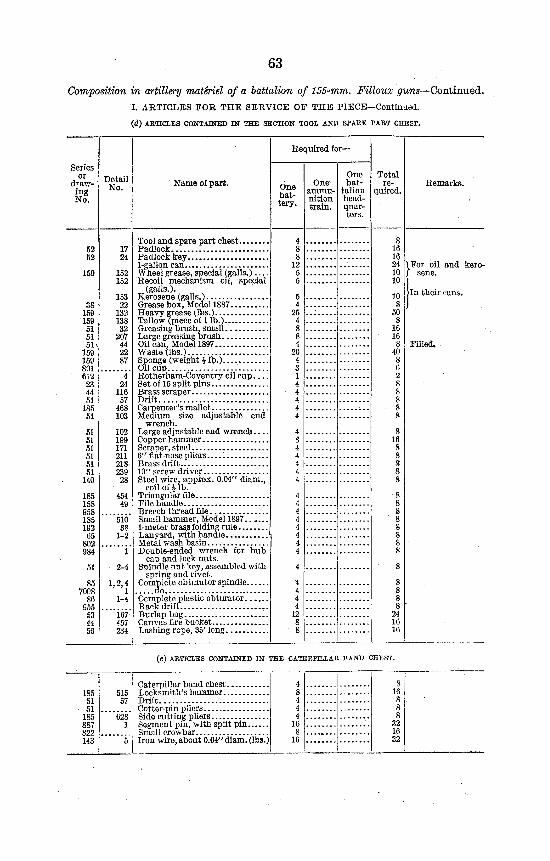
Composition in artillery matSriel of a battalion of 155-mm. Filloux guns—Continued. I. ARTICLES FOR THE SERVICE OF THE PIECE—Continued.
(&) ARTICLES CONTAINED IN THE SECTION TOOL AND SPARE PART CHEST.
Detail No. Name of part.
Required for-
One battery.
One ammunition train.
One bat
talion head-quarters.
Total re
quired. Remarks.
17 24
152 152
153 22
132 138 32
207 44 22 87
4 24
116 57
468 103
102 199 171 211 218 239 28
454 49
510 88
1-2
1
2-4
1,2,4
1-4
167 457 234
Tool and spare part chest -Padlock Padlock key 1-gallon can wheel grease, special (galls.) Recoil mechanism oil, special
(galls.). Kerosene (galls.) Grease box, Model 1887 Heavy grease (lbs.) Tallow (piece of 1 lb.) Greasing brush, small Large greasing brush Oil can, Model 1897 Waste (lbs.) Sponge (weight £ lb.) Oil cup Rotherham-Coventry oil cup Set of 15 split pins Brass scraper Drift Carpenter's mallet Medium size adjustable end
wrench. Large adjustable end wrench Copper hammer Scraper, steel 6" flat-nose pliers Brass drift 10" screw driver Steel wire, approx. 0.04" diam.,
coil of £ lb. Triangular file File handle Breech thread file Small hammer, Model 1897 1-meter brass folding rule Lanyard, with handle Metal wash basin Double-ended wrench for hub
cap and lock nuts. Spindle nut key, assembled with
spring and rivet. Complete obturator spindle ,
Complete plastic obturator Rack drift Burlap bag Canvas fire bucket Lashing rope, 35' long
\For oil and kero-/ sene.
lln their cans.
Filled.
(e) ARTICLES CONTAINED IN THE CATERPILLAR BAND CHEST.
Caterpillar band chest Locksmith's hammer. Drift Cotter-pin pliers Side cutting pliers Segment pin, with split pin Small crowbar Iron wire, about 0.04" diam. (lbs.)
4 8 4 4 4
16 8
16
8 16 8 8 8
32 16 32
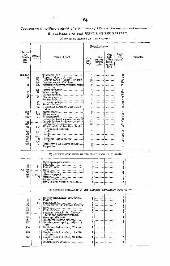
64
Composition in artillery materiel of a battalion of 155-mm. Filloux guns—Continued. II. ARTICLES FOR THE SERVICE OF THE BATTERY.
(a) SPARE EQUIPMENT AND ACCESSORIES.
Detail No.
235 247 248 298
303 10
1-4 5-8 14
1-2
1-3
1-3 2
1,2,4 3
Name of part.
Traveling bar Rope, 1" diam., 50' long Lashing ropes 1" diam., 33' long. Lashing ropes 16' 6" long Maneuvering lever, -wooden, with
iron ring. Handspike, iron Wheel wedge Wedge handle Cleaning sponges Sponge cover Greasing sponges Short rammer Unloading rammer, with exten
sion. Mirror stake Mirror rule Wooden mall Caterpillar band segment, mark B Caterpillar band segment, mark A Caterpillar band shoe Wheel, with rubber tires, brake
drum, and hub cap. do do do
Complete limber spring. do
Bolt sleeves for limber spring Tarpaulin
Required for—
One battery.
1 4
16 . 8
8
4 8 8 1 2 1 1 1
2 1 4 4
12 12 1
1 1 1 1 1 2 2
One ammunition train.
One bat
talion head-quarters.
Total re
quired.
2 8
32 16 16
8 16 16 2 4 2 2 2
4 2 8 8
24 24 2
2 2 2 2 2 4 4
Remarks.
(6) ARTICLES CONTAINED IN THE SIGHT SPARE PART CHEST.
Sight spare part chest Padlock Padlock key Sight Sight case Mirror support Mirror Range tables, set of Data book for chief of section
1 1 1 1 1 1 4 4 8
2 2 2 2 2 2 8 8
16
(c) ARTICLES CONTAINED IN THE BATTERY MECHANICS' TOOL CHEST.
Battery mechanics' tool chest. . . Padlock Padlock key Screw driver fo? rack lock bushing Rack drift Pawl lever Spanner wrench for disassem
bling the obturator spindle. Rack spindle drift Counterpoise spacing clip Counterpoise spring adjusting
pin. Double-ended wrench, 77 mm.,
54 mm. Double-ended wrench, 40 mm.,
26 mm. Double-ended wrench, 20 mm.,
17 mm. 10-ihch screw driver
2 4 2 4 2 , 4 2 4 2 4 2 4 2 4
2 4 4 8 2 4
4 8
4 8
4 8
4 8
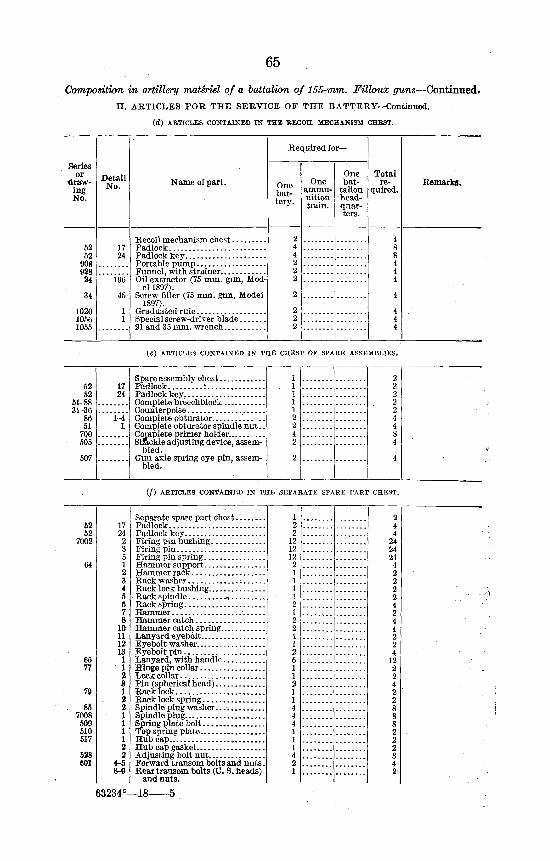
65
Composition in artillery mathiel of a battalion of 155-mm. Filloux guns—Continued. II . ARTICLES FOE THE SERVICE OF THE BATTERY—Continued.
(d ) ARTICLES CONTAINED IN THE RECOIL MECHANISM CHEST.
Series or
drawing No.
52 52
906 928 24
34
1020 1056 1055
Detail No.
17 24
196
45
1 1
Name of part.
Padlock
Oil extractor (75 mm. gun, Model 1897).
Screw filler (75 mm. gun, Model 1897).
Special screw-driver blade
Required for—
One battery.
2 4 4 2 2 2
2
2 2 2
One ammunition train.
One bat
talion head-quarters.
Total re
quired.
4 8 8 4 4 4
4
4 4 4
Remarks.
(«) ARTICLES CONTAINED IN THE CHEST OF SPARE ASSEMBLIES.
1-4 1
Spare assembly chest Padlock : Padlock key Complete breechblock Counterpoise Complete obturator .. Complete obturator spindle nut. Complete primer holder...... ... Sfc&ekle adjusting device, assem
bled. Gun axle spring eye pin, assem
bled.
1 2 1 2 1 2 1 2 1 2 2 4 2 4 4 8 2 4
2 4
( / ) ARTICLES CONTAINED IN THE SEPARATE SPARE PART CHEST.
52 52
7002
64
65 77
79
85 7008 509 510 517
528 601
17 24 2 3 5 1 2 3 4 5 6 7 8
10 11 12 13 1 1 2 3 1 2 2 1 1 1 1 2 2
4-5 8-9
Firing pin spring
Rack washer Rack lock bushing Rack spindle •. Rack spring Hammer • Hammer catch Hammer catch spring Lanyard eyebolt Eyebolt washer Eyebolt pin Lanyard, with handle Hinge pin collar Lock collar Pin (spherical head) Rack lock Rack lock spring Spindle plug washer.. .•
Hubcap
Forward transom bolts and nuts. Rear transom bolts (C. S. heads)
and nuts.
1 2 2
12 12
n 2 1 1 1 1 2 1 2 2 1 1 2 6 1 1 2 1 1 4 4 4 1 1 1 4 2 1
2 4 4
24 24 24 4 2 2 2 2 4 2 4 4 2 2 4
12-2 2 4 2 2 8 8 8 2 2 2 8 4 2
63234°—18-
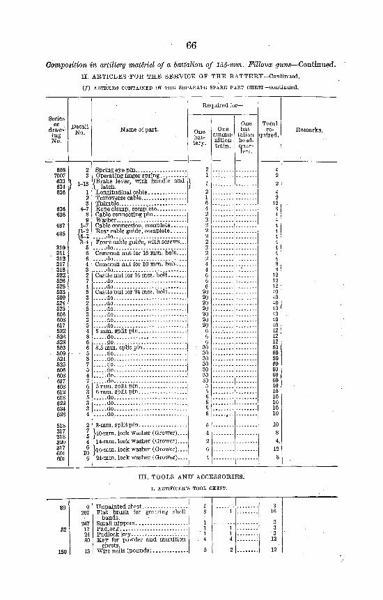
66
Composition in artillery materiel of a battalion of 155-mm. Filloux guns—Continued. II . ARTICLES FOR THE SERVICE OF THE BATTERY—Continued.
(/) ARTICLES CONTAINED IN THE SEPARATE SPARE PART CHEST—Continued.
Detail No.
1 2 3
4-7
1-7
3-4 5
Name of part.
Spring eye pin Operating finger spring
/Brake lever, with handle and \ latch. Longitudinal cable Transverse cable Thimble Rope clamp, complete Cable connecting pin Washer Cable connection, complete Rear cable guide, complete
do Front cable guide, with screws... . . . .do Common nut for 16 mm. bo l t— . . . .do Common nut for 10 mm. bo l t— . . . .do Castle nut for 16 mm. bolt . . . .do . . . d o Castle nut for 24 mm. bolt
do do
. . . .do
do do
3 mm. split pin. . . do do
3.5 mm. split pin. do do do do : . .
. . . . .do do
5 mm. split pin. . . 6 mm. split pin. . .
do do do do
8-mm. split pin ko-mm. lock washer (Grower). 14-mm. lock washer (Grower).
[•16-mm. lock washer (Grower). 24-mm. lock washer (Grower).
Required f or-
One battery.
One ammunition train.
One bat
talion head-quarters.
Total re
quired.
III . TOOLS AND" ACCESSORIES.
I. ARTIFICER'S TOOL CHEST.
0 207
247 17 24
Unpainted chest Flat brush for greasing shell
bands. Small nippers Padlock Padlock key Key for powder and munition
ctlGSts Wire nails (pounds)
1 8
1 1
" • 1
.. 4
5
1
1 1 4
2
3 16
3 3 3
12
12
Remarks.
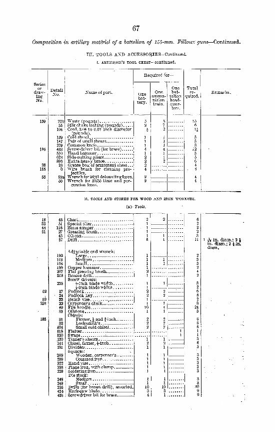
67
Composition in artillery materiel of a battalion of 155-mm. Filloux guns—Continued.
III. TOOLS AND ACCESSORIES—Continued,
i. ARTIFICER'S TOOL CHEST—continued.
Series or
drawing No.
Detail No.
159
185
38 185
22b 35
104
139 147 229 438 510 628 896 26 0
50
Name of part.
Waste (pounds) Silk choke lashing (pounds) Cord, 0.04 to 0.08 inch diameter
(pounds). Cold chisel Pair of small shears Common knife Screw-driver bit (for brace) Hand hammer Side-cutting pliers Extra heavy brace Grease box of armament chest.. Wire brush for cleaning pro-
W'ectiles. rench for 24/31 detonating fuses
Wrench for 30/55 time and percussion fuses.
Required for—
One battery.
One ammunition train.
One bat
talion head-quarters.
Total re
quired. Remarks.
n. TOOLS AND STOEES FOB WOOD AND IRON WORKERS.
(a) Tools.
18 33 44 51
52
52 158
185
48 51
118 27 43 57
102 103 104 199 207 218
238
17 24 33 22 49 83
31 32
104 118 120 130 144 191
289 299 322 336 339
348 349 355 434 438
Chest
Drift
Adjustable end wrench:
Small
Screw drivers:
Chisels:
Flatter
Squares:
Die stock:
Small J Drills (for breast drill), assorted.
2 1 1 1 1 5
1 1 1 1 2 1
1 1 2 2 1 1
10 1
2 2 2
1 2 1
1 1 1 1 1
1 1
10 3 4
2
1 1
1 1
1
2 2
1 4 1
2 2 2
1 2 1
1 1 1 1 1
1 1
10 3 1
1 1
6 2 2 2 3
11
2 3 3 2 4 2
3 2 6 6 2 3
24 3
6 6 6 1 1 3 6 3
3 3 3 3 3
3 3
30 9 9
1 -rV in. diam.; 2 | in. diam.; 2 Jin. diam.
•
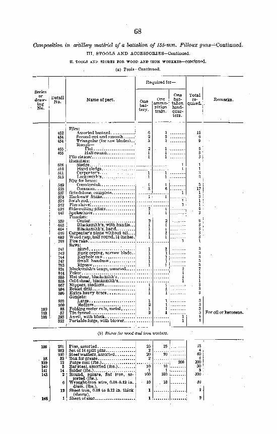
68
Composition in artillery materiel of a battalion of 155-mm. Filloux guns—Continued. III . STOOLS AND ACCESSORIES—Continued.
n. TOOLS ANP STORES FOR •WOOD AND IRON WORKERS—continued.
(o) Tools—Continued.
Series or
drawing No.
192 193 199
Detail No.
452 454 454
455 455
506 510 511 515
549 553 557 573 578 582 628 647
659 663 664 686 699 708
741 742 744 747 752 824 844 855 855 867 894 896
899 900 88 57
293 352
Name of part.
Files:
Second cut and smooth Triangular (for saw blades).. Rough—
Flat
Hammers:
Bits for brace:
Punches:
Blacksmith's, with handle...
Carpenter's plane without bit Wood rasp, half round, 1J inches.
Saws:
Buck coping, narrow blade..
Small handsaw
Blacksmith's tongs, assorted
Gimlets:
Required for—
One battery.
6 2 3
2 1 1
1 1
1 3
1
2 1
, 2 1 1 1 1
1 1 1
1 2 1 2
One ammunition train.
3 2 3
1 1 1
1 1
1 6
1
1 1
2 1 1 1 1
1 1 1 1 1
1 1 1
1 1 1 1
One bat
talion head-quarters.
1 1
1
1 1
1
2 1 1 1
1 1
Total re
quired.
15 6 9
5 3 3
1 1 3 3
3 12 1 3 1 1 5 3
6 3 3 3 3 1
3 3 3 3 3 2 1 1 1 3 3 3
3 5 3 5 1 1
Remarks.
For oil or kerosene.
(6) Stores for wood and iron workers.
211 212 220 32 12 5
14 2
Pins, assorted Set of 14 split pins Steel washers, assorted Box for grease Forge coal (lbs.) Bar steel, assorted (lbs:) Solder (lbs.) Round, square, flat iron, as
sorted (lbs.). Wrought-iron wire, 0.08-0.12 in.
diam. (lbs.). Sheet iron, 0.08 to 0.12 in. thick
(sheets). Sheet of zinc
10 1
100
10 1
100
75 4
60 4
200 30 3
300
30
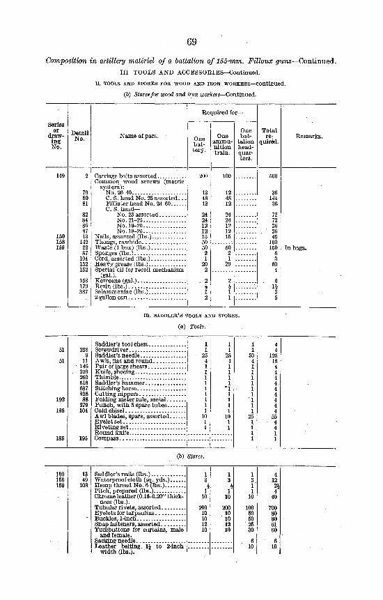
69
Composition in artillery materiel of a battalion of 155-mm. Filloux guns—Continued. I l l TOOLS AND ACCESSORIES—Continued.
n. TOOLS AND STORES FOE "WOOD AND IRON -WORKERS—continued.
(6) Stores for wood and iron workers—Continued.
Detail No. Name of part.
Required for—
One battery.
200
12 48 12
24 24 12 12 15 50 50 2 1
20 2
. 2 } 1 2
One ammunition train.
100
12 48 12
24 24 12 12 15
50 2 1
20
2 1 1 1
One bat
talion head-quarters.
Total re
quired.
500
36 144 36
72 72 36 36 45
100 150
6 3
60 4
6 11 3 5
Remarks.
Carriage bolts assorted Common wood screws (metric
system): No. 26-40 C. S. head No. 25 assorted.. Fillister head No. 24-60 C. S. h e a d -
No . 23 assorted No.21-25 No.19-20 No.18-25
Nails, assorted (lbs.) Thongs, rawhide Waste (1 box) (lbs.) Sponges (lbs.) Cord, assorted (lbs.) Heavy grease (lbs.) Special oil for recoil mechanism
(gal.). Kerosene (gal.) Resin (lbs.) Salammoniac (lbs.) 2-gallon can
Inl
m . SADDLER'S TOOLS AND STORES.
(a) Tools.
238 9 11 146 229 260 516 637 828 88
279 104
195
Saddler's tool chest Screwdriver Saddler's needle Awls, flat and round Pair of large shears Knife, shoeing Thimble Saddler's hammer Stitching horse Cutting nippers Folding meter rule, metal . . Punch, with 5 spare tubes.. Cold chisel Awl blades, spare, assorted. Eyelet set Riveting set Round knife Compass
4 4
125 16 4 4 4 4 4 4 4 4 4
55 4 4 1 1
(6) Stores.
13 49
108
Saddler's nails (lbs.) Waterproof cloth (sq. yds.) Hemp thread No. 6 (lbs.) Pitch, prepared (lbs.) Chrome leather (0.16-0.20" thick
ness (lbs.). Tubular rivets, assorted Eyelets for tarpaulins Buckles, 1-inch Snap fasteners, assorted Tumbuttons for curtains, male
and female. Sacking needle Leather belting. 11 to 2-inch
width (lbs.).
1 3 4
1 10
200 10 10 12 10
1 3 i
1 10
200 10 10 12 10
1 3 1 1
10
100 50 50 25 30
6 10
4 12 2i 4
40
700 80 80 61 60
- 6 10
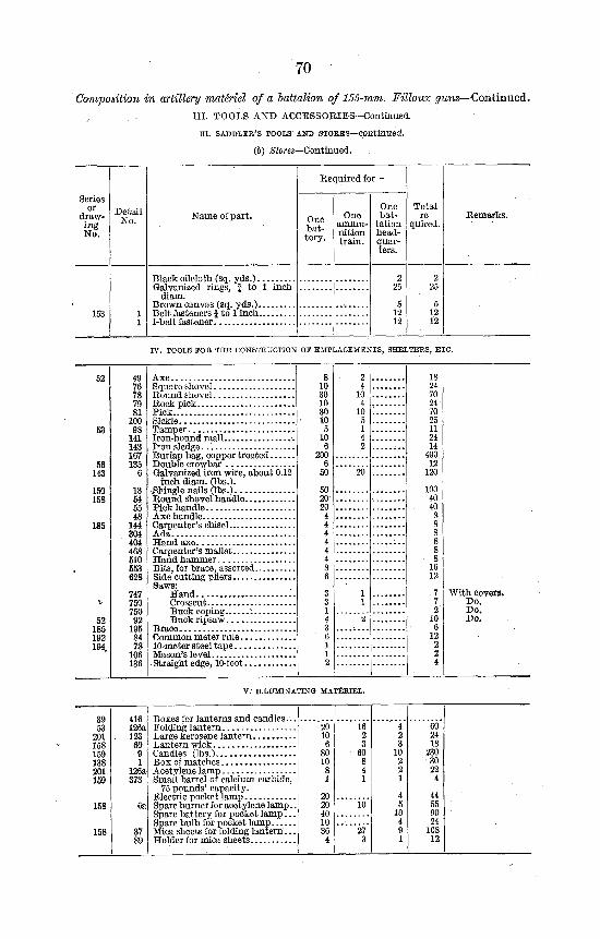
70
Composition in artillery materiel of a battalion of 155-mm. Filloux guns—Continued. III. TOOLS AND ACCESSORIES—Continued.
in. SADDLER'S TOOLS AND STOBES—continued.
(6) Stores—Continued.
Detail No. Name of part.
Required for—
One battery.
One ammunition train.
One bat
talion headquarters.
Total re
quired. Remarks.
Black oilcloth (sq. yds . ) . . . Galvanized rings, f to 1
diam. Brown canvas (sq. yds,) . . . Belt fasteners f to 1 inch... I-belt fastener
inch
IV. TOOLS FOR THE CONSTRUCTION OS EMPLACEMENTS, SHELTERS, ETC.
76 78 79 81 100 98 141 143 167 135 6
13 54 55 48 144 304 404 468 510 553 628
747 750 750 92 195 84 78 106 136
Axe Square shovel Round shovel Rock pick Pick Sickle Tamper Iron-bound mall Iron sledge Burlap bag, copper treated Double crowbar Galvanized iron wire, about 0.12
inch diam. fibs.). Shingle nails (lbs.) Round shovel handle. Pick handle Axe handle Carpenter's chisel Adz Hand axe Carpenter's mallet . . . . Hand hammer Bits, for brace, assorted Side cutting pliers Saws:
Hand Crosscut Buck coping.. : Buck ripsaw
Brace Common meter rule 10-meter steel tape Mason's level Straight edge, 10-foot
8 10 30 10 30 10 5 10 6
200 6 50
50 20 20 4 4 4 4 4 4 8 6
3 3 1 4 3 6 1 1 2
2 4 10 4 10 5 1 4 2
20
1 1
2
18 24 70 24 70 25 11 24 14 400 12 120
100 40 40 8 8 8 8 8 8 16 12
7 7 2 10 6 12 2 2 4
With covers. Do. Do. Do.
V. ILLUMINATING MATERIEL.
Boxes for lanterns and candles.. Folding lantern Large kerosene lantern Lantern wick Candles (lbs.) Box of matches Acetylene lamp Small barrel of calcium carbide,
75 pounds' capacity. Electric pocket lamp Spare burner for acetylene lamp. Spare battery for pocket lamp. . Spare bulb for pocket lamp Mica sheets for folding lantern.. Holder for mica sheets
20 10 6 80 10 8 1
20 20 40 10 36 4
16 2 3 60 8 4 1
10
27 3
4 2 3 10 2 2 1
4 5 10 4 9 1
60 24 18 230 30 22 4
44 55 90 24 108 12
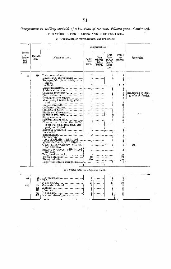
71
Composition in artillery materiel of a battalion of 155-mm. Filloux guns—Continued. IV. MATERIEL FOR LIAISON AND FIRE CONTROL,
(o) Instruments for reconnaissance and fire control.
Detail No. Name of part.
Required for-
One battery.
One ammunition train.
One bat
talion head-quarters.
Total re
quired. Remarks.
33i Instrument chest. Plane table, 28x43 inches Topographic plane table, with
tripod. Declinator Large declinator Alidade slope ruler Celluloid protractor Zinc protractor Graduated zinc square Metal rule, 1 meter long, gradu
ated Peigne' compass Ordinary compass Clinometer ruler Stadia rod (2 meters) 20-meter steel wire Sitogoniometer Sitogoniometer case Observation circle (in mills)
complete with field glass, support, and tripod.
Parallax protractor Barometer Thermometer Chronograph. Jobin theodolite, with tripod Morin theodolite, with tripod Observation telescope, with tri
pod and case. Scissors telescope, with tripod
and case. Position data book Firing data book Firing bulletin Logarithmic tables (in grades)...
5 10
100
}Graduated in deci-grades clockwise.
10 20
200 1
Do,
(6) Small tools for telephonic truck.
78 81
144 405 511 747 867
Round shovel , Pick Naiis"(iT3sjV.v.';;;;: Carpenter's chisel... Hatchet Hammer Wood saw Medium size nippers
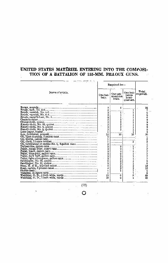
UNITED STATES MATERIEL ENTERING INTO THE COMPOSITION OF A BATTALION OF 155-MM. FILLOUX GUNS.
Name of article.
Required for-
One battery.
One ammunition
train
One battalion head
quarters.
Borax, pounds Brush, sash, No. 3-0 Brush, varnish, No. 4-0 Brush, varnish, No. 6-0 Brush, camel's-hair, No. 1 Chamois skins , Crocus cloth, quires Emery cloth, No. 00, quires Emery cloth, No. 0, quires Emery cloth, No. %, quires Lens paper, reams Lye, powdered, pounds Oil, light slushing, 2 gallon cans Oil, sperm, gallon cans Oil, clock, 1-ounce bottles Oil, lubricating or engine No. 1, 5-gallon cans Turpentine, gallon cans Paint, Japan drier, quart cans Paint, black, gallon cans Paint, blue-gray, gallon cans Paint, dark buff, gallon cans Paint, light olive-green, gallon cans Sandpaper, No. 00, quires Sandpaper, No. 2£, quires Soap, H. & H., 5-pound cakes Soap, castile, 1-pound cakes Stores chest Vaseline, 5|-ounce cans Webbing, O. D., § inch wide, yards Webbing, O. D., 1 inch wide, yards
(72)
o
10
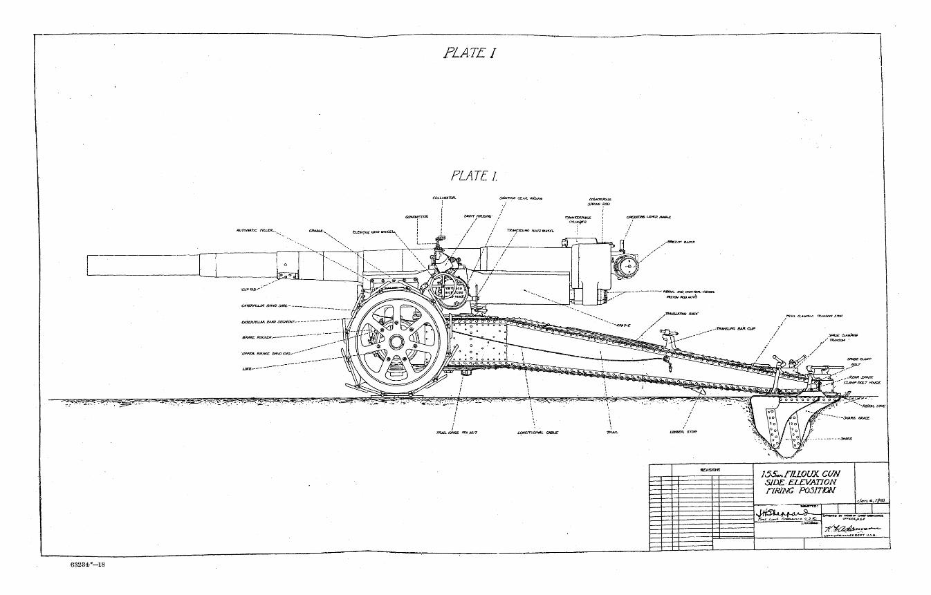
PLATE I
PLATE I.
StSHTItiG CCAO. j C t o W f t
0PCXAT7H& LZVEJZ MM&Ui
£ » E E = W auxx
TXA/l CLAMP/Ht: TRANSOM J
^es
' /'
\°\ \oo\
«,'' z ) P y - ^
^^/i^tf|2
u o„ o^ojftim.n
6 0 0 o~o~o" g^
S(~~ 4 / o l Va$
Jfl»OE OJIM/VS
f'' TXAHSa* •
SPUDS CLAHP
ecr
rvt fr"^ * , - - «
p~q .0
t ^ 1
_
...GEAR 3P*0£
•' CtAMPaOLT HtHSS
'.' *~~KCCOIL sioe
SWkKZ BRKC
63234-°—18

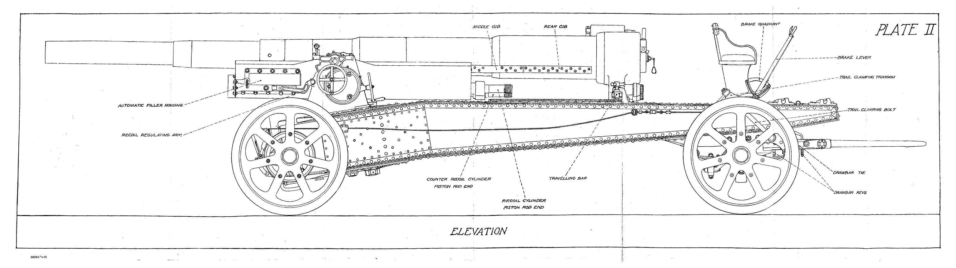
MIDDLE GIB
AUTOMATIC FILLER HOUSING.
RECOIL REGULATING ARA<\
. „ BRAKE LEVER
PLATE H
_ _ ~- TRAIL CLAMPING TRANSOM
-TRAIL CLAMPING SQL T
^DRAW&AR ThE
^DRAW&AH KEYS
ELEVATION
63234 *™*18

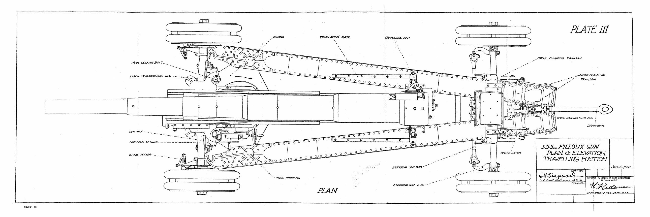
nrn
TRAIL LOCKING30LT.
fRONT MAA/OEUVENJNG LUu .̂ _._
nrn PLATE m
• TRAIJ. CLAMPfNG TttiA/SOAt
^r 3/*J£>£ Ct^Mftfi/G
Gun AXLE. -_. _
GUN AXt.fi SPRING
£>HMl f&CKER—^. _
' IJL1J PLAN
J^S^FJLLOL/X GUM PLAN <3c ELEWTION
TRA/ELim POSITION
SUBMITTED; .
/frj-l JL'&sK C?f&lrzcLri.ce. 64S./&
^M
EXAMINED:
Jan.6>/9/8.
APPR0CD BY OROtR & CH/EF OKDNANCEI 1 ' ornctR. A C . r
C A P J O f f D N ^ N C C p g p y . U - ^
63234^ 18

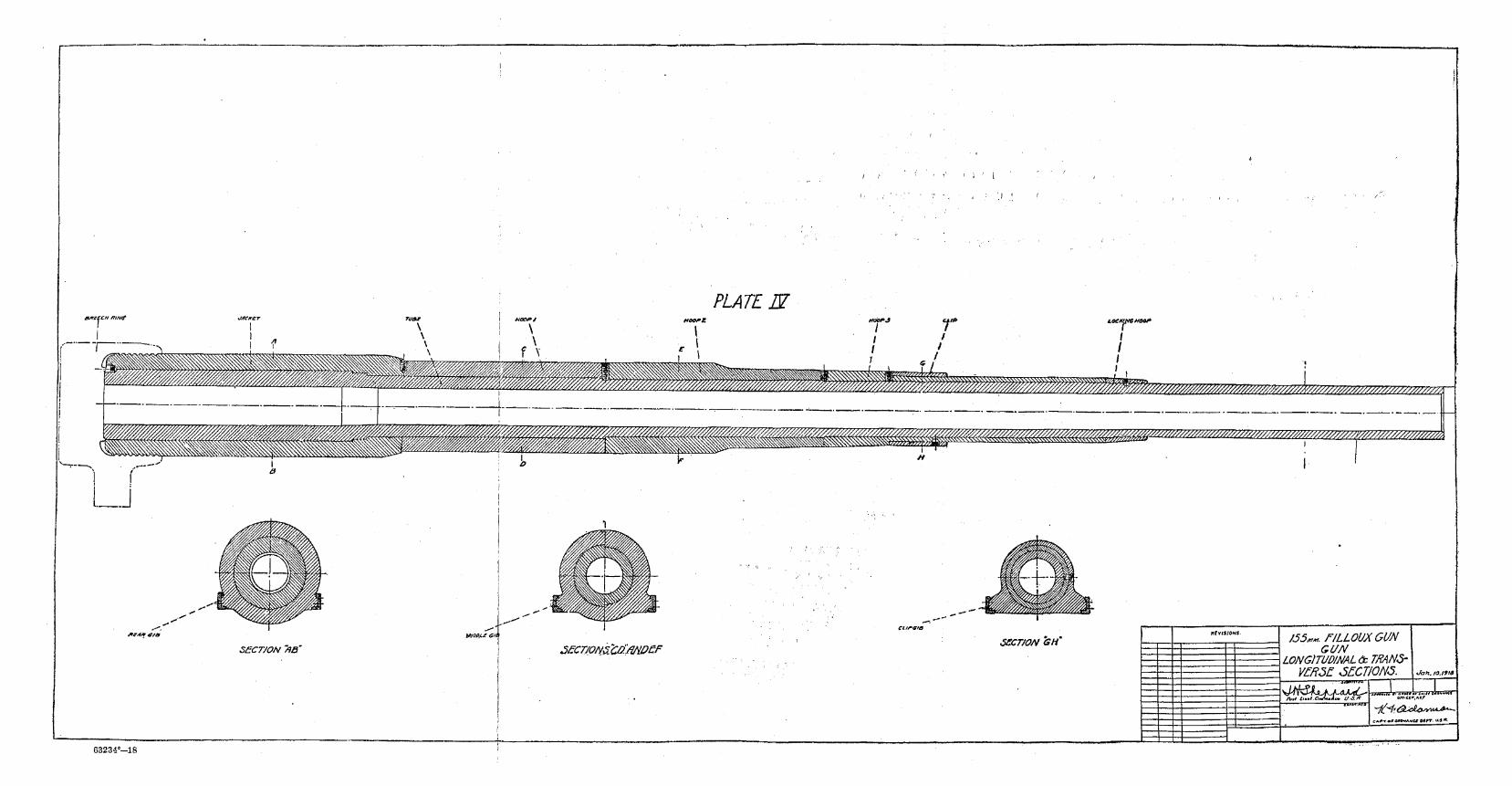
e>3234°~18

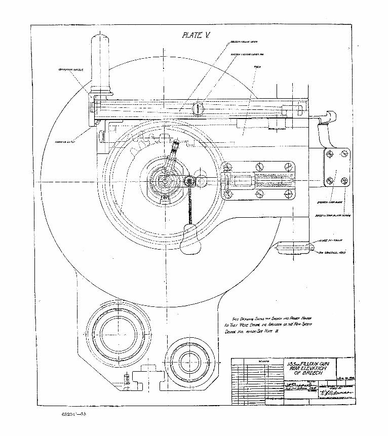
63234°—18

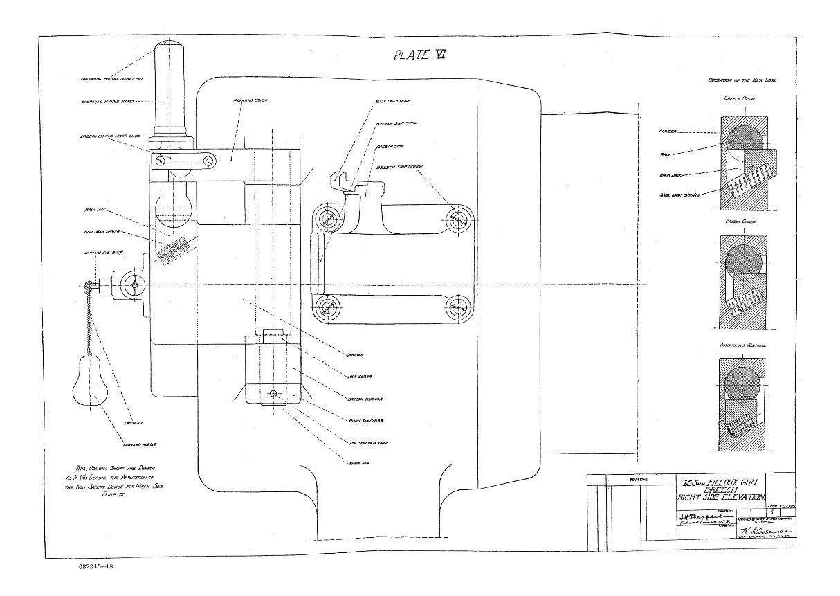
7hrs. DRAWING SHOWS me. 3nEeav
As fr Ptts &£?&?£ THE Amjar/aN w
m£ Akiy >5vsrr Dey/cE fOR MVCH <5EE
FljT£.JZL.
63234°—18
OfE/tATto* OP THE /fax COCK
KacKjoct;
RACK tax &v»He
166MM. NLLOUXGUN DBEECH
XR1GHT 51DE ZIXVA T/OM
fint 1,-ot < prmvtDB* ottotn or cmt.r (JWNAICX

Pf&ME/T M>10£R /Mf£U£ 3/K/fS.
•SffNoie fe/r /cey;
smjuE piue tf/otiEK
TH/S £k*WN6 <5f*3t& V/£ B/tEEOt As fr
lyks Ge/fMs me AmicA'rraH <?/= war At&v
SAFETY £kr/ce f&r /&/<?* 3ee fhirs JZ_
lJSMM.riLLjOUX GUN
VERTICAL JECT2QH
/ w l~*r oJ^Jic i/5./t. BSHsasr
I v f e » 7 / , / y f
7t& CArr OHonAHCt D f w m n ,
63234°—18

aareor etoot
nomaesif/s COUAH
nto*j spams *SMf£7 AMMBT ctiav
Tka Oturim SMOHS rue OKeeat Ar AI Benfre me AfvucAVON OF THE Afar SvETy DEVICE /w? Wh/GH •See /htre JZ.
HAMiiBt arcHwatts
iAtrrA/u>ev£-Bu7 / / / / / /
' I . / •/'. /
/ /. /
ntat snuas juat apce itsuwe
63234-°—18

PLATE IX. ^SAT£7Y UXK HOUSING
F I
1
!
1 i
Mousing sav&y i
SAFETY IOCK MOUSING
1
t
i smmoc* j i
SAFETY HOOT- . ___
sOfOXtzmG f7N6£R $Pff/N&
-SfXMS $OCX£T
-OP&rAT.w? /?AKse
• P*#*CJt HOLDEH BOOY
•MHMEK HSLDBft PLUG
•Firntia nn BUSH ins
-ffRINS flNSTBP
FIRING- PIN SPRING
SPINOLB PLUS
16S*u fILLOUX <sm BREECH
SAFETY DEVICE <Am./*>./&»
ortKm,Acj>.

63234°—18

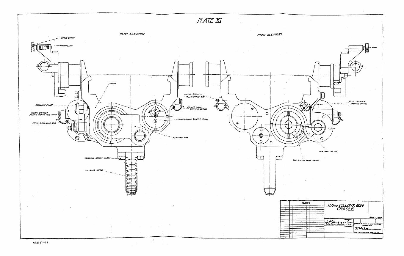
..acme $c*ew
REAR ELEVATION
PLATEXI
•ffecoii en/wen fJLLlNG ORIFICE PLUS
eawv7z» RSXJIL - ,
rrujim ounce nus
CouHTEp-mrooiL teSfnve swse.
ASGOH ff£GMA7im ARM -
E1EYATHG SECTOR
PrstN f«x> roxe.
63234°—18
FRONT ELEVATian
CAM GEAR SECIOR
RBCOHi. CYLINDER CHAINING ORIFICE.
155»»F1LL0UXGUN. CRADLE.
. • ttawinco:" *&>* t'.l9/B

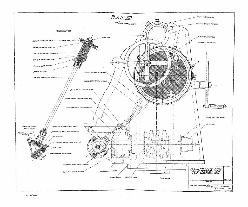
63234°—18

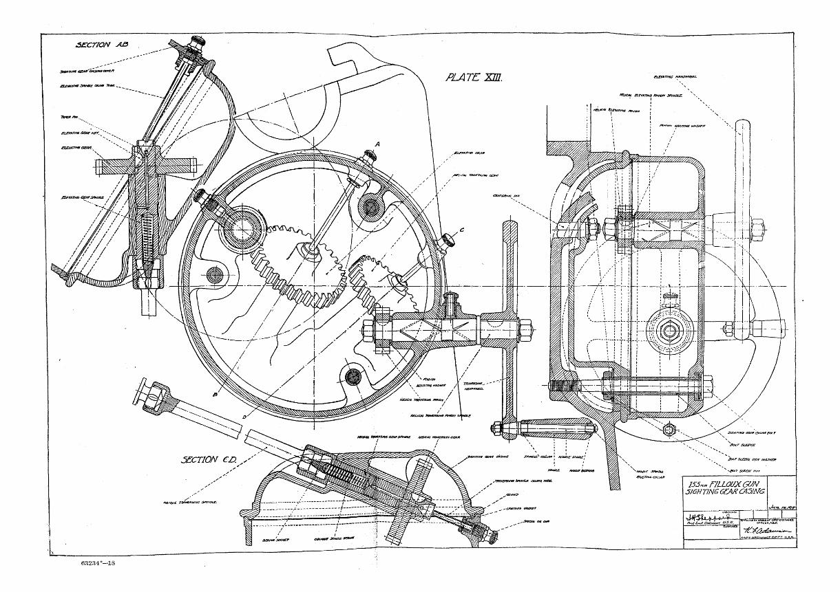
SECTION A3
3mtnn€ eCA*~CA3inecere'i
etemnna GOVT nrK
£t£VAr/HG /A4JV0»ftiBZL
KBJCAL apTATmo fmnyr s/was.
m&M>**Gev>.
£ocr Sleeve
* W Si£Bf£ t<X* 1MJXST
lJ5«„nLL0UXGUN SIGHTING GEAR CXSim
•Jan. />4>./9/r
O* O*VG*0t**tttX
63234°—18

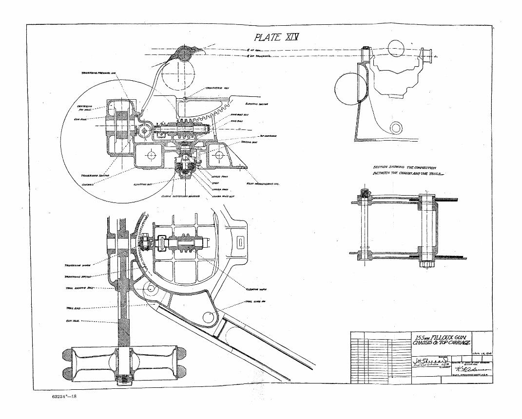
PLATE W-
63234°—18
SECTION SHOWING THE COKNECTiaN
&ETWSEN THE CHASSIS AND THE 7WLS~~
r̂
155MH/7LL0UX GUM CHAS5I5 <Sc lOPCMff/A&L
\ti-?Q. , . . 52 1 r<.r*z'li*»t 0<3i«lrt U5 A
t A « /jf, f$t&
j
7i?£H%C4&***<t~* T*rr. oirPNANCC n r r r I U A

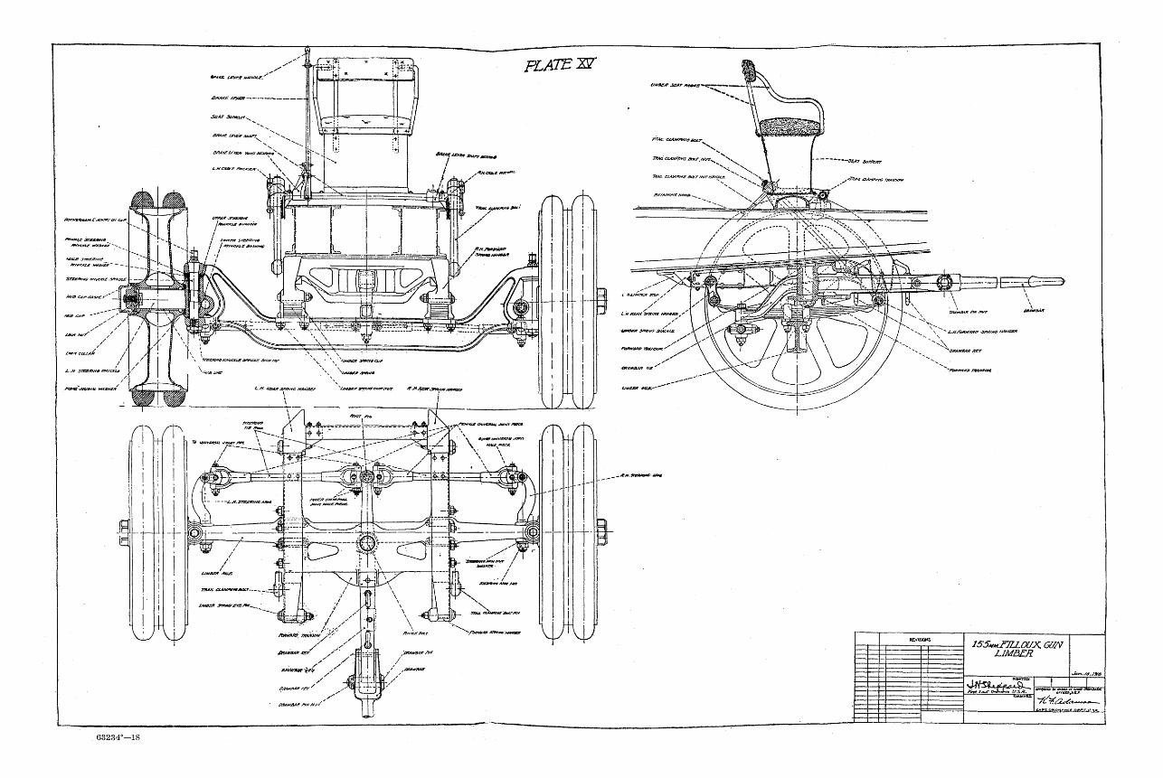
Ft ATE W
63234°—18
tMSav sar ntvts
£.Mfbm**/N* &&/*&. MWSSR
'Awtv&ur iter
-fi&rmtjrp rw&aH
„&Mjr»amM£ <4«v
155«Hf7LLaJX. GUN LIMBER
nw* t~-r aj~i*<* USA. h W Vf^vo tttmet*cruder,

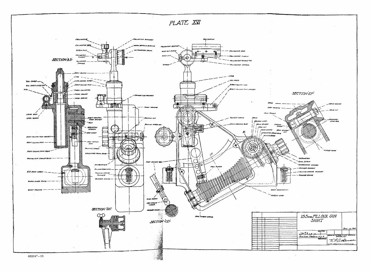
63234°—18


![Materiel Soudure[1]](https://img.pdfslide.net/doc/110x75/5695d3c81a28ab9b029f2c65/materiel-soudure1.jpg)


