Embed Size (px)
Citation preview

Handling instructions for GISMA connectors
HI – 2007 - 001
Document: replaces
MV 2000-020, MV 2000-030 and MV 2005 - 011
First issue: 15.07.2008 Rev.-Index: -X- From: 20.02.2019
Copyright by:
GISMA GmbH
Page 2 of 32
Content 1. GENERAL .................................................................................................................................... 3 2. SCOPE ......................................................................................................................................... 3 3. PROTECTION, HANDLING AND SHIPMENT ............................................................................ 3 4. UNPACKING ................................................................................................................................ 4 5. STORAGE .................................................................................................................................... 4
5.1. Short Term Connector Storage ........................................................................................ 4 5.2. Long Term Connector Storage ......................................................................................... 4
6. Jumper handling and mounting................................................................................................ 4 6.1. Jumper handling ................................................................................................................ 4
7. DEPLOYMENT & MAINTENANCE ............................................................................................. 5 7.1. SUBSEA CONNECTORS SERIES 10 ................................................................................ 5
7.1.1. General ........................................................................................................................ 5 7.1.2. Live Mate / Demate .................................................................................................... 6 7.1.3. Protection of receptacle’s pin contacts .................................................................. 6 7.1.4. Removal of Marine Growth and Calcareous Deposits ........................................... 6 7.1.5. Connector Handling .................................................................................................. 7 7.1.6. Mounting dimensions .............................................................................................. 10
7.2. SUBSEA TITANIUM CONNECTORS SERIES 16 ........................................................... 11 7.2.1. General ...................................................................................................................... 11 7.2.2. Live Mate / Demate .................................................................................................. 12 7.2.3. Protection of receptacle’s pin contacts ................................................................ 12 7.2.4. Removal of Marine Growth and Calcareous Deposits ......................................... 12 7.2.5. Connector Handling ................................................................................................ 12 7.2.6. Test Port ................................................................................................................... 13 7.2.7. Pressure Balanced Oil Filled Hose (PBOF) ........................................................... 13
7.3. SUBSEA CONNECTORS SERIES 22 .............................................................................. 15 7.3.1. Live Mate / Demate .................................................................................................. 15 7.3.2. Protection of receptacle’s pin contacts ................................................................ 15 7.3.3. Removal of Marine Growth and Calcareous Deposits ......................................... 16 7.3.4. Connector Handling ................................................................................................ 16 7.3.5. Mounting dimension ................................................................................................ 17
7.4. SUBSEA CONNECTORS SERIES 40 .............................................................................. 22 7.4.1. Live Mate / Demate .................................................................................................. 22 7.4.2. Protection of receptacle’s pin contacts ................................................................ 22 7.4.3. Removal of Marine Growth and Calcareous Deposits ......................................... 23 7.4.4. Cleaning process for ferrules ................................................................................. 23 7.4.5. Connector Handling ................................................................................................ 24
7.5. SUBSEA CONNECTORS SERIES 80 .............................................................................. 25 7.5.1. General ...................................................................................................................... 25 7.5.2. Live Mate / Demate .................................................................................................. 25 7.5.3. Protection of receptacle contact pins ................................................................... 26 7.5.4. Removal of Marine Growth and Calcareous Deposits ......................................... 26 7.5.5. Diver Mate Connectors ............................................................................................ 26 7.5.6. Stab Plate Connectors ............................................................................................ 28 7.5.7. ROV Connectors ...................................................................................................... 28 7.5.8. Mounting hole for flange-receptacle ...................................................................... 31
Handling instructions for GISMA connectors
HI – 2007 - 001
Document: replaces
MV 2000-020, MV 2000-030 and MV 2005 - 011
First issue: 15.07.2008 Rev.-Index: -X- From: 20.02.2019
Copyright by:
GISMA GmbH
Page 3 of 32
GISMA ELECTRICAL & FIBRE OPTIC CONNECTORS - PROTECTION, STORAGE, SHIPMENT, UNPACKING,
DEPLOYMENT & MAINTENANCE INSTRUCTIONS 1. GENERAL
Thank you for purchasing a GISMA product. The information that follows is an overview of the
protection, storage, shipment, unpacking, deployment and maintenance instructions for GISMA
electrical and fibre optic products.
GISMA recommend the termination and handling of all equipment only be undertaken by suitably
trained and qualified personnel.
2. SCOPE This procedure includes information on the following connector types:
GISMA series 10
GISMA series 16
GISMA series 22
GISMA series 40
GISMA series 80 Sections 3, 4, 5 and 6 handle general information applicable to all GISMA connectors. Section 7 then provides specific information relevant to each connector series.
3. PROTECTION, HANDLING AND SHIPMENT
GISMA electrical, fibre and hybrid connectors are manufactured primarily from materials such as
stainless steel 1.4404 / 1.4571 (316L / 316Ti), marine bronze (CW307G) and titanium Grade 5, and
as such are designed to withstand harsh saliferous environments. However, the connector insulator
and exposed parts are susceptible to mechanical damage if not adequately protected. Dust caps are
fitted to all GISMA connectors before transport, but can be fitted with POM protective caps or
pressure watertight protective caps, if specified by the customer. Pressure watertight caps must
remain in place until the connectors are ready for the underwater mating process.
The connectors are generally relatively small items of equipment, and therefore, can be shipped
singularly or in multiples. Care should be taken to protect the connector with bubble wrap or similar
wrapping materials to avoid surface damage during transit. Dust caps or POM protective caps must
be fitted at all times during transport.
If the connectors are assembled onto cables these must be suitably coiled and secured with appropriate material (tape, cable strap) to prevent uncoiling during transit. Recommended bend radius for storage/transport of cables, refer to cable specification or jumper drawing.
Any connector-specific handling and transport advice is contained within the appropriate section
further on in this document.
Handling instructions for GISMA connectors
HI – 2007 - 001
Document: replaces
MV 2000-020, MV 2000-030 and MV 2005 - 011
First issue: 15.07.2008 Rev.-Index: -X- From: 20.02.2019
Copyright by:
GISMA GmbH
Page 4 of 32
4. UNPACKING
Remove wrapping material taking care to inspect for any surface damage or items that may have
become separated from the connector, such as ‘O-ring' seals. Do not use a knife to cut the wrapping
material, as this may cause damage to any elastomeric parts of the connector. Do not remove any
kind of protection caps until connectors are ready for installation. On removal do not allow the cables
to drag over the edges of the packing crate.
5. STORAGE
5.1. Short Term Connector Storage
Prior to installation the connectors are sensitive to environments where grit and dirt are present. To prevent ingress of the above, they should be stored in a clean dry area and be protected by bubble wrap or similar wrapping and packing material. Protective caps must be fitted if supplied.
5.2. Long Term Connector Storage
The connectors must be stored in a clean dry area and be protected by bubble wrap or similar.
Suitable protective caps must be fitted, and the storage temperature should be ideally between
+5°C and +20°C. For short times and during transport storage temperature can be between -40°C
and +70°C. Humidity of the store room should be below 75%. Very moist or very dry conditions
should be avoided. The connectors should be protected from sunlight and artificial light with a
high ultra violet content.
The connectors should not be allowed to come into contact with solvents, oil, greases or any other
semi-solid materials.
If storage time is longer than 2 years, outer o-rings have to be replaced prior to installation.
6. Jumper handling and mounting
6.1. Jumper handling
GISMA connectors can be delivered as part of the jumper assembly. All terminated connectors
are delivered with dust caps for protecting the contacts and the insulator against damage and
dust. These caps have to be removed before subsea usage.
Before mounting inspect the jumper and especially the cable for damages and debris.
Lightly grease the locking threads of the receptacles, pressure hull penetrators and the through
bulkhead receptacles e.g. with GISMA-FETT LP 430 (strongly recommended at stainless steel and
titanium threads).
After mounting the cable has to be fixed closed to the structure (first fix point 500 mm behind the
connector’s endbell and than every 500 mm) to prevent movement and turning of the jumper
cable.
Take care that all connectors are correctly mated and locked with the correct mounting torque or
protected by pressure watertight protective caps before going subsea. For defined mounting
instructions refer to the different connector series and special jumper drawings.
Prior to installation the connectors are sensitive to environments where grit and dirt are.
Handling instructions for GISMA connectors
HI – 2007 - 001
Document: replaces
MV 2000-020, MV 2000-030 and MV 2005 - 011
First issue: 15.07.2008 Rev.-Index: -X- From: 20.02.2019
Copyright by:
GISMA GmbH
Page 5 of 32
7. DEPLOYMENT & MAINTENANCE
The following section details deployment and maintenance instructions for all GISMA connectors &
cables, categorised by product type. Please refer to the appropriate section as listed below:
7.1 - Subsea connectors’ series 10
7.2 - Subsea connectors’ series 16
7.3 - Subsea connectors’ series 22
7.4 - Subsea connectors’ series 40
7.5 - Subsea connectors’ series 80
All information contained within this section is generic. Where customer or project-specific information is required, please refer to the relevant project specification or scope of supply.
For further technical information refer to the catalogues of the different series or special drawings.
Note: It is important to isolate and earth prior to disconnect in order to remove any stray
charges in the system. If left, this can induce corrosion on the exposed pins once the plug is
removed.
The connector shall have the following periodic maintenance checks:
Examine the connector for signs of damage.
Check the locking sleeve, these shall be tight, if loose refer to assembly instruction
for torque values, where appropriate.
7.1. SUBSEA CONNECTORS SERIES 10
7.1.1. General The series 10 sizes 1 to 7 range of connectors has been developed for long term reliable signal and low power control system applications associated with offshore installations. The underwater mateability of the range of signal connectors series 10 (contact-Ø 1mm and 1,5mm) is achieved by using a patented, conical sealing system at each contact and a lip gasket.
For further technical information refer to the catalogue of series 10 or special drawings. The connector range series 10 comprises standard power connectors for high voltage and high current application as well. NOTE! These connectors are not underwater pluggable. Please ask for detailed product information. Connectors are usually supplied with dust caps. The dust caps need to be removed prior to mating the connectors.
All mild steel sealing interfaces shall be inlayed with Inconel 625, or similar, where no additional
protection can be provided. This is to prevent localised pitting of the interface.
Stainless steel (1.4404/ 1.4571 comparable to 316L/316Ti) or titanium grade 5 stab plate con-
nectors must be connected to the CP (Cathodic Protection) system at all times. If the connector
is designed with a fixed flange and screw mounting, an additional CP connecting would not be
required. Super Duplex stainless steel connectors should be isolated from the CP system to
reduce the possibility of hydrogen embrittlement.
Handling instructions for GISMA connectors
HI – 2007 - 001
Document: replaces
MV 2000-020, MV 2000-030 and MV 2005 - 011
First issue: 15.07.2008 Rev.-Index: -X- From: 20.02.2019
Copyright by:
GISMA GmbH
Page 6 of 32
If the connectors are to be left unmated in seawater for any length of time, pressure watertight
protective caps must be used to protect the contacts. Over exposure will increase the risk of
corrosion damage or marine growth on the contact surfaces of the pin contacts. This could lead
to damage to the seals and insulation within the socket contacts.
The appropriate test connector must always be used to make electrical contact during testing.
UNDER NO CIRCUMSTANCES should a foreign object (such as a screwdriver, test probe or
crocodile clip) be used as a test connection as this could damage the seals and insulation. Such
actions will invalidate the warranty of the connector.
Attention: The customer is responsible for the safe operation of the connectors and cable
systems. All necessary protective measures must be taken.
Test connectors or free touchable connectors with metal shell must be connected to the
earth conductor.
The series 10 range of connectors can be supplied either singularly or as part of a harness
assembly. All series 10 connectors require the following acceptance tests during termination:
Mating test
Insulation Resistance test
High Voltage test
Continuity test
Cable terminations can be performed on-site or offshore by GISMA trained personnel where the
cable cannot easily be moved or transported. Each series 10 connector has been mated,
hydrostatically tested (applies to receptacles only) and electrically proven prior to despatch.
Termination of these connectors should only be undertaken by trained personnel.
7.1.2. Live Mate / Demate
The series 10 range of connectors are designed to be mated / de-mated with POWER OFF.
7.1.3. Protection of receptacle’s pin contacts
Under no circumstances the contacts should be exposed to seawater with power on. If this
situation does occur the contact surfaces of the contacts will very rapidly degrade by electrolytic
action. If these damaged pins are subsequently mated into a socket insert there is a very high
risk of damage to the insulation and seals within the plug.
7.1.4. Removal of Marine Growth and Calcareous Deposits
To remove calcite growth topside or subsea from GISMA connectors, a solution of 50% Citric Acid
is recommended. All seawater exposed elastomeric materials in GISMA connectors have been
fully tested against 50% Citric Acid and are compatible for duration of 1 hour. In addition, the
thermoplastic materials have good resistance to Citric Acid.
Other acid cleaners, such as >50% Acetic Acid, should not be used as they may cause
deterioration of the elastomeric materials.
Chiselling and abrasive methods are not recommended. Use of a water jet is acceptable, but the
jet should not be directed onto the pins at the front and onto any elastomer part like insulators
and boot seals.
Handling instructions for GISMA connectors
HI – 2007 - 001
Document: replaces
MV 2000-020, MV 2000-030 and MV 2005 - 011
First issue: 15.07.2008 Rev.-Index: -X- From: 20.02.2019
Copyright by:
GISMA GmbH
Page 7 of 32
NOTE: Keep the connector mated at any cleaning operation!
7.1.5. Connector Handling
Installation instruction for jam nut receptacles and flange receptacles according MV 2004-034 or
customer design.
The mounting hole and the supporting surface must be clean and without any damages.
Pre Mating Check
The connector that is to be joined must be free of dirt and foreign matter. Coaxial- and fibre-
optic inserts must be protected against moisture.
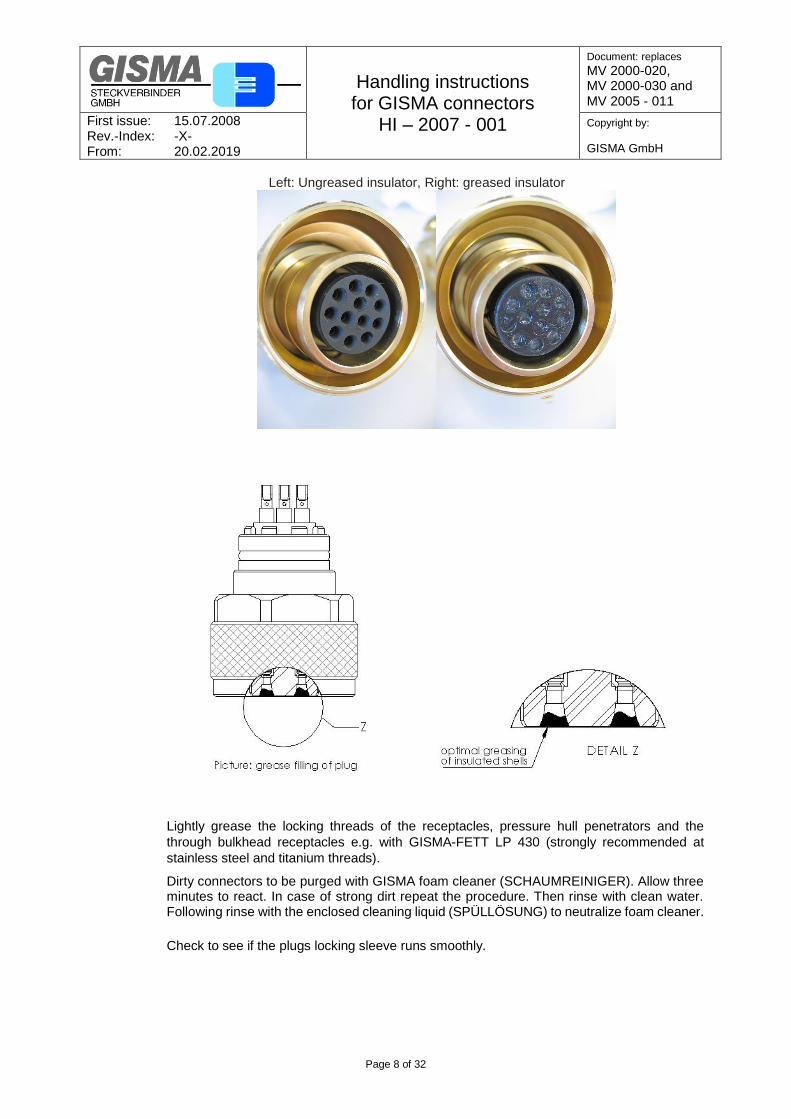
Insulator greasing
Before the initial coupling the front side of the socket connectors must be greased with
GISMA-grease EK2 (part no.: GISMA-FETT EK2), to fill the conical seal cavities with grease
(see drawing below). Greasing ensures that the two elastomer Insulators in the conical seals
can slide perfectly into its final position and thus best seal. After 5 underwater matings the
connector must be greased again (applies only to series 10).
For greasing the GISMA connectors - Grease EK2 is specified. The corresponding compatibility of this Grease is with all elastomers used in GISMA (insulating, sealing elements) given. At the same time, this product has excellent properties. The grease EK2 is not conductive. By mating the GISMA connector the contact forces applied mean the grease is completely displaced from the contact area, so that the grease does not affect the contact resistance. At the same time this ensures a high Insulation resistance - even with insertions in moist environments. Typical properties
reduced friction and wear
prevents leakage
contact oxidation resistance
neutral against plastics
Amount of grease to be used The Insulator should be greased so that the insulating sealing cone is 70-100 % filled with grease.
Attention For hybrid connectors (eg fibre optic and coax combined) it is necessary to ensure that only the region of the insulating elastomer must be greased. Fibre-optic and coaxial contacts must be kept absolutely free from grease to prevent losses.
Handling instructions for GISMA connectors
HI – 2007 - 001
Document: replaces
MV 2000-020, MV 2000-030 and MV 2005 - 011
First issue: 15.07.2008 Rev.-Index: -X- From: 20.02.2019
Copyright by:
GISMA GmbH
Page 8 of 32
Left: Ungreased insulator, Right: greased insulator
Lightly grease the locking threads of the receptacles, pressure hull penetrators and the
through bulkhead receptacles e.g. with GISMA-FETT LP 430 (strongly recommended at
stainless steel and titanium threads).
Dirty connectors to be purged with GISMA foam cleaner (SCHAUMREINIGER). Allow three minutes to react. In case of strong dirt repeat the procedure. Then rinse with clean water. Following rinse with the enclosed cleaning liquid (SPÜLLÖSUNG) to neutralize foam cleaner.
Check to see if the plugs locking sleeve runs smoothly.
Handling instructions for GISMA connectors
HI – 2007 - 001
Document: replaces
MV 2000-020, MV 2000-030 and MV 2005 - 011
First issue: 15.07.2008 Rev.-Index: -X- From: 20.02.2019
Copyright by:
GISMA GmbH
Page 9 of 32
Maintenance
For the installation of O-rings the general guidelines for O-ring assembly have to be taken
into account. Mainly the correct installation (e.g. position), cleanness and greasing with
GISMA-FETT EK2 have to be ensured.
In case, that the O-rings carrying assemblies are installed for more than 2 years to a structure
and then will be disassembled, we generally recommend to replace the O-rings.
We recommend changing the O-rings at latest after 5 years, if the O-rings are used as
directed.
For assemblies, which will only be installed once, our experience shows the estimated
lifetime may be double. For operating temperatures between +5°C to +40°C, longer lifetimes
can be expected.
Defective clamps to be replaced.
Alignment
Put the plug onto the receptacle. Twist the connector until the keyway locks into place.
While tightening the locking sleeve with the one hand, simultaneously feed in the connector
with the other.
Mating
After tightening the locking sleeve by hand, screw it into the receptacle fitting using corresponding wrenches. If the locking sleeve is designed with a safety screw, tighten it. For defined clamping torque refer to GISMA document “Torque overview”.
Cathodic Protection
Stainless steel (1.4404/ 1.4571 comparable to 316L/316Ti), marine bronze (CW307G) or
titanium grade 5 diver mate connectors must be connected to the CP (Cathodic Protection)
system at all times. Super Duplex stainless steel connectors should be isolated from the CP
system to reduce the possibility of hydrogen embrittlement.
Pressure testing
Series 10 plugs and receptacles are longitudinal watertight up to the specified pressure
range (see dimensional drawings). Every receptacles and terminated plug for underwater
applications will be pressure tested acc. Customer or GISMA specification.
Hybrid connectors with coaxial and fibre optic contacts have to be tested with protective
caps to prevent deposits from decreasing the connectors performance!
Safety
Test connectors or free touchable connectors with metal shell must be connected to the
earth conductor.
Handling instructions for GISMA connectors
HI – 2007 - 001
Document: replaces
MV 2000-020, MV 2000-030 and MV 2005 - 011
First issue: 15.07.2008 Rev.-Index: -X- From: 20.02.2019
Copyright by:
GISMA GmbH
Page 10 of 32
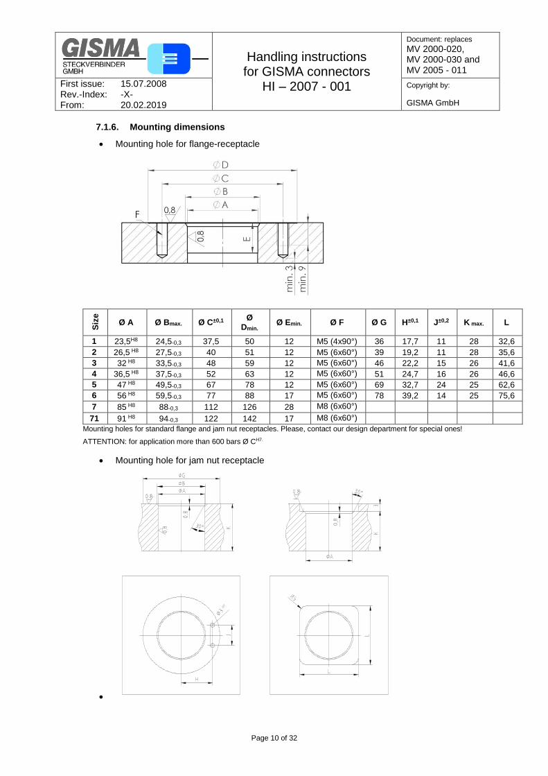
7.1.6. Mounting dimensions
Mounting hole for flange-receptacle
Siz
e
Ø A Ø Bmax. Ø C±0,1
Ø Dmin.
Ø Emin. Ø F Ø G H±0,1 J±0,2 K max. L
1 23,5H8 24,5-0,3 37,5 50 12 M5 (4x90°) 36 17,7 11 28 32,6
2 26,5 H8 27,5-0,3 40 51 12 M5 (6x60°) 39 19,2 11 28 35,6
3 32 H8 33,5-0,3 48 59 12 M5 (6x60°) 46 22,2 15 26 41,6
4 36,5 H8 37,5-0,3 52 63 12 M5 (6x60°) 51 24,7 16 26 46,6
5 47 H8 49,5-0,3 67 78 12 M5 (6x60°) 69 32,7 24 25 62,6
6 56 H8 59,5-0,3 77 88 17 M5 (6x60°) 78 39,2 14 25 75,6
7 85 H8 88-0,3 112 126 28 M8 (6x60°)
71 91 H8 94-0,3 122 142 17 M8 (6x60°)
Mounting holes for standard flange and jam nut receptacles. Please, contact our design department for special ones!
ATTENTION: for application more than 600 bars Ø CH7.
Mounting hole for jam nut receptacle
Handling instructions for GISMA connectors
HI – 2007 - 001
Document: replaces
MV 2000-020, MV 2000-030 and MV 2005 - 011
First issue: 15.07.2008 Rev.-Index: -X- From: 20.02.2019
Copyright by:
GISMA GmbH
Page 11 of 32
7.2. SUBSEA TITANIUM CONNECTORS SERIES 16
7.2.1. General The series 16 sizes 3,4,5,6 ranges of connectors has been developed for long term reliable signal and low power control system applications associated with offshore installations. The long term watertightness of the mating area at the signal connectors series 16 (contact-Ø 1,5 mm) is achieved by using a patented, conical sealing system at each contact, a lip gasket and an O-ring seal. NOTE! These connectors are not underwater mateable. A part of series 16 connectors are especially designed for oil compensated systems and are pressure proof from both sides. NOTE! Please make sure to use the appropriate connector in your system. For further technical information refer to the catalogue series 16 or special drawings. Connectors are usually supplied with dust caps. The dust caps need to be removed prior to mating the connectors.
All mild steel sealing interfaces shall be inlayed with Inconel 625, or similar, where no additional
protection can be provided. This is to prevent localised pitting of the interface.
If the connectors are to be left unmated in seawater for any length of time, pressure watertight
protective caps must be used to protect the contacts. Over exposure will increase the risk of
corrosion damage or marine growth on the contact surfaces of the pin contacts. This could lead
to damage to the seals and insulation within the socket contacts.
The appropriate test connector must always be used to make electrical contact during testing.
UNDER NO CIRCUMSTANCES should a foreign object (such as a screwdriver, test probe or
crocodile clip) be used as a test connection as this could damage the seals and insulation. Such
actions will invalidate the warranty of the connector.
Attention: The customer is responsible for the safe operation of the connectors and cable
systems. All necessary protective measures must be taken.
Test connectors or free touchable connectors with metal shell must be connected to the
earth conductor.
The series 16 range of connectors can be supplied either singularly or as part of a harness
assembly. All series 16 connectors require the following acceptance tests during termination:
Mating test
Insulation Resistance test
High Voltage test
Continuity test
Cable terminations can be performed on-site or offshore by GISMA trained personnel where the
cable cannot easily be moved or transported. Each series 16 connector has been mated,
hydrostatically tested (applies to receptacles only) and electrically proven prior to despatch.
Termination of these connectors should only be undertaken by trained personnel.
Handling instructions for GISMA connectors
HI – 2007 - 001
Document: replaces
MV 2000-020, MV 2000-030 and MV 2005 - 011
First issue: 15.07.2008 Rev.-Index: -X- From: 20.02.2019
Copyright by:
GISMA GmbH
Page 12 of 32
7.2.2. Live Mate / Demate
The series 16 range of connectors are designed to be mated / de-mated with POWER OFF.
7.2.3. Protection of receptacle’s pin contacts
Under no circumstances the contacts should be exposed to seawater with power off or on. If this
situation does occur the contact surfaces of the contacts will very rapidly degrade by electrolytic
action. If these damaged pins are subsequently mated into a socket insert there is a very high
risk of damage to the insulation and seals within the plug.
7.2.4. Removal of Marine Growth and Calcareous Deposits
To remove calcite growth topside or subsea from GISMA connectors, a solution of 50% Citric Acid
is recommended. All seawater exposed elastomeric materials in GISMA connectors have been
fully tested against 50% Citric Acid and are compatible for duration of 1 hour. In addition, the
thermoplastic materials have good resistance to Citric Acid.
Other acid cleaners, such as >50% Acetic Acid, should not be used as they may cause
deterioration of the elastomeric materials.
Chiselling and abrasive methods are not recommended. Use of a water jet is acceptable, but the
jet should not be directed onto the pins at the front and onto any elastomer part like insulators
and boot seals.
NOTE: Keep the connector mated at any cleaning operation!
7.2.5. Connector Handling
Pre Mating Check
The connector that is to be joined must be free of dirt and foreign matter.
Prior to mating a series 16 connector, each conical seal of the socket insert should be filled
with a small amount of GISMA grease EK-2 (part.no.: GISMA-FETT EK-2) dielectric grease.
Lightly grease the locking threads of the receptacles GISMA-FETT LP 430.
Dirty connectors to be purged with GISMA foam cleaner (SCHAUMREINIGER). Allow three minutes to react. In case of strong dirt repeat the procedure. Then rinse with clean water. Following rinse with the enclosed cleaning liquid (SPÜLLÖSUNG) to neutralize foam cleaner.
Check to see if the plugs locking sleeve runs smoothly.
Maintenance
For the installation of O-rings the general guidelines for O-ring assembly have to be taken
into account. Mainly the correct installation (e.g. position), cleanness and greasing with
GISMA FETT EK2 have to be ensured.
In case, that the O-rings carrying assemblies are installed for more than 2 years to a structure
and then will be disassembled, we generally recommend to replace the O-rings.
We recommend changing the O-rings at latest after 5 years, if the O-rings are used as
directed.
Handling instructions for GISMA connectors
HI – 2007 - 001
Document: replaces
MV 2000-020, MV 2000-030 and MV 2005 - 011
First issue: 15.07.2008 Rev.-Index: -X- From: 20.02.2019
Copyright by:
GISMA GmbH
Page 13 of 32
For assemblies, which will only be installed once, our experience shows the estimated
lifetime may be double. For operating temperatures between +5°C to +40°C, longer lifetimes
can be expected.
Defective clamps to be replaced.
Alignment
Put the plug onto the receptacle. Twist the connector until the keyway locks into place.
While tightening the locking sleeve with the one hand, simultaneously feed in the connector
with the other.
Mating
After tightening the locking sleeve by hand, screw it into the receptacle fitting using corresponding wrenches. For defined clamping torque refer to GISMA document “Torque overview”.
Cathodic Protection
For titanium grade 5 connectors the cathodic protection is to be considered by the customer.
7.2.6. Test Port
Series 16 receptacles are equipped with test ports according to API specification 16D. The integrity of the sealing of the mating and flange area could be tested. The test ports should be sealed by the provided test port sealing plugs at all times. For testing the sealing plugs will be replaced by a test port adapter and a test pressure pump will be connected via Minimess hose. A pressure drop test according to customer specifications will show the integrity of the sealing. After the test, the sealing plugs must be carefully installed with clean and greased o-rings.
7.2.7. Pressure Balanced Oil Filled Hose (PBOF)
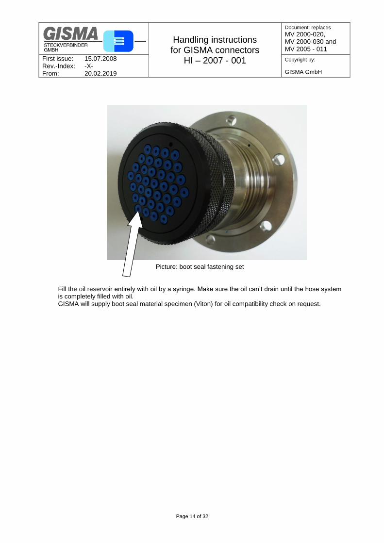
Series 16 plugs and receptacles are pressure proof from mating side as well as termination side. This enables the usage of pressure balanced oil filled hose adapters and hoses (PBOF). NOTE! There are also receptacles for atmospheric junction boxes. Please make sure to use the appropriate connector in your system. API specifications require boot seals as additional sealing system for PBOF. Boot seals must match the wire diameter. Before applying the boot seal, a portion of GISMA grease EK-2 must be applied inside the boot seal by use of a syringe. GISMA highly recommends the usage of a boot seal fastening set. This fastening set keeps the boot seals in place, restricts the bending radius and forms an extra oil reservoir.
Handling instructions for GISMA connectors
HI – 2007 - 001
Document: replaces
MV 2000-020, MV 2000-030 and MV 2005 - 011
First issue: 15.07.2008 Rev.-Index: -X- From: 20.02.2019
Copyright by:
GISMA GmbH
Page 14 of 32
Picture: boot seal fastening set Fill the oil reservoir entirely with oil by a syringe. Make sure the oil can’t drain until the hose system is completely filled with oil. GISMA will supply boot seal material specimen (Viton) for oil compatibility check on request.
Handling instructions for GISMA connectors
HI – 2007 - 001
Document: replaces
MV 2000-020, MV 2000-030 and MV 2005 - 011
First issue: 15.07.2008 Rev.-Index: -X- From: 20.02.2019
Copyright by:
GISMA GmbH
Page 15 of 32
7.3. SUBSEA CONNECTORS SERIES 22
The connector range series 22 is especially designed for long term subsea use under harsh
conditions, e. g. submarines. It can be supplied either singularly or as part of a harness assembly.
Series 22 connectors are only dry pluggable.
All GISMA connectors require the following acceptance tests during the terminations:
Mating test
Insulation Resistance test
High Voltage test
Continuity test
Cable terminations can be performed on-site or offshore by GISMA trained personnel where the
cable cannot easily be moved or transported. Each GISMA connector is fitted with a pin or socket
insulator which has been tested prior to despatch.
Termination of series 22 connectors should only be undertaken by trained personnel.
All series 22 connectors must be fitted with a mating connector or a pressure watertight protective
cap prior to subsea installations. Connectors must not be energised subsea unless coupled with
a mating connector or fitted with a pressure watertight protective cap, in order to prevent
electrolytic damage to the contacts when exposed to sea water.
All mild steel sealing interfaces shall be inlayed with Inconel 625, or similar, where no additional
protection can be provided. This is to prevent localised pitting of the interface. If not possible
grease the mounting hole and the supporting surface with corrosion preventing fluid (for example
Fluid Film) as a minimum.
Stainless steel (1.4404/ 1.4571 comparable to 316L/316Ti) or titanium grade 5 stab plate
connectors must be connected to the CP (Cathodic Protection) system at all times. If the
connector is designed with a fixed flange and screw mounting, an additional CP connecting would
not be required. Super Duplex stainless steel connectors should be isolated from the CP system
to reduce the possibility of hydrogen embrittlement.
Attention: The customer is responsible for the safe operation of the connectors and cable
systems. All necessary protective measures must be taken.
NOTE: Series 22 cannot be used for oil compensated systems or oil compensate hose
terminations.
For further technical information refer to the catalogue of series 22 or special drawings.
7.3.1. Live Mate / Demate
The series 22 range of connectors are designed to be mated / de-mated with POWER OFF.
7.3.2. Protection of receptacle’s pin contacts
Under no circumstances the contacts should be exposed to seawater with power off or on. If this
situation does occur the contact surfaces of the contacts will very rapidly degrade by electrolytic
action. If these damaged pins are subsequently mated into a socket insert there is a very high
risk of damage to the insulation and seals within the plug.
Handling instructions for GISMA connectors
HI – 2007 - 001
Document: replaces
MV 2000-020, MV 2000-030 and MV 2005 - 011
First issue: 15.07.2008 Rev.-Index: -X- From: 20.02.2019
Copyright by:
GISMA GmbH
Page 16 of 32
7.3.3. Removal of Marine Growth and Calcareous Deposits
To remove calcite growth topside or subsea from GISMA connectors, a solution of 50% Citric Acid
is recommended. All seawater exposed elastomeric materials in GISMA connectors have been
fully tested against 50% Citric Acid and are compatible for duration of 1 hour. In addition, the
thermoplastic materials have good resistance to Citric Acid.
Other acid cleaners, such as >50% Acetic Acid, should not be used as they may cause
deterioration of the elastomeric materials.
Chiselling and abrasive methods are not recommended. Use of a water jet is acceptable, but the
jet should not be directed onto the pins at the front and onto any elastomer part like insulators
and bootseals.
NOTE: Keep the connector mated at any cleaning operation!
7.3.4. Connector Handling
Installation instruction for jam nut receptacles, bulkheads and pressure hull penetrators
The flange and mounting hole has to be manufactures according VG 85 519 or customer
design.
The mounting hole and the supporting surface must be clean and without any damages.
Grease the mounting hole and the supporting surface with corrosion preventing fluid (for
example Fluid Film).
Push the pressure hull penetrator into mounting hole and locate the penetrator with the
centering pin according to your installation drawing. The connector keyway must be in the
right position.
For easy handling we recommend the GISMA pipe spanners: 22.94.001 / 22.94.002 and 22.94.003. If castellated nuts are used, the Mounting tool 22.94.020, 22.94.021 or 22.94.022 is necessary.
Pre Mating Check
The connector that is to be joined must be free of dirt and foreign matter. Coaxial- and fibre-
optic inserts must be protected against moisture.
Prior to mating an series 22 connector, each conical seal of the socket insert should be filled
with a small amount of GISMA grease EK2 (part no.: GISMA-FETT EK-2) dielectric grease.
Installation conditions for 90° PUR moulding endbells
Plugs with 90° PUR moulding endbells have to be mounted without bending forces at the
PUR moulding.
Handling instructions for GISMA connectors
HI – 2007 - 001
Document: replaces
MV 2000-020, MV 2000-030 and MV 2005 - 011
First issue: 15.07.2008 Rev.-Index: -X- From: 20.02.2019
Copyright by:
GISMA GmbH
Page 17 of 32
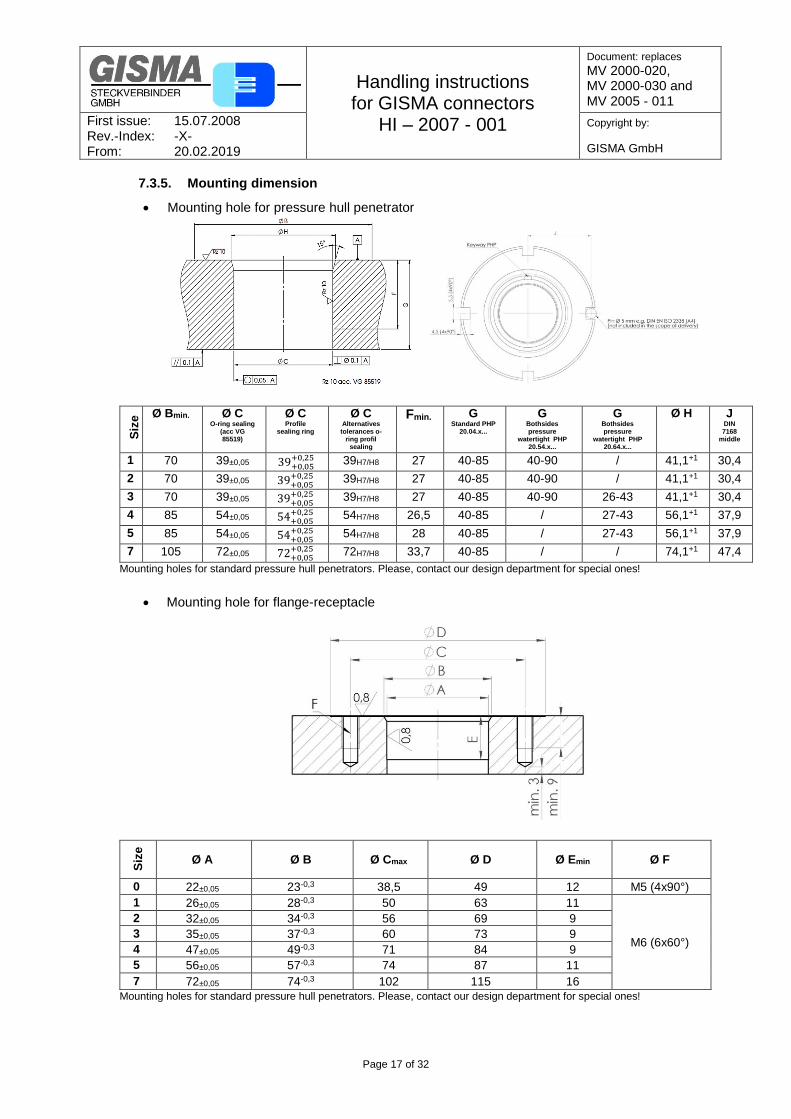
7.3.5. Mounting dimension
Mounting hole for pressure hull penetrator
Siz
e Ø Bmin.
Ø C O-ring sealing
(acc VG 85519)
Ø C Profile
sealing ring
Ø C Alternatives tolerances o-
ring profil sealing
Fmin. G Standard PHP
20.04.x...
G Bothsides pressure
watertight PHP 20.54.x...
G Bothsides pressure
watertight PHP 20.64.x...
Ø H
J DIN 7168
middle
1 70 39±0,05 39+0,05 +0,25 39H7/H8 27 40-85 40-90 / 41,1+1 30,4
2 70 39±0,05 39+0,05+0,25 39H7/H8 27 40-85 40-90 / 41,1+1 30,4
3 70 39±0,05 39+0,05+0,25 39H7/H8 27 40-85 40-90 26-43 41,1+1 30,4
4 85 54±0,05 54+0,05+0,25 54H7/H8 26,5 40-85 / 27-43 56,1+1 37,9
5 85 54±0,05 54+0,05+0,25 54H7/H8 28 40-85 / 27-43 56,1+1 37,9
7 105 72±0,05 72+0,05+0,25 72H7/H8 33,7 40-85 / / 74,1+1 47,4
Mounting holes for standard pressure hull penetrators. Please, contact our design department for special ones!
Mounting hole for flange-receptacle
Siz
e
Ø A Ø B Ø Cmax Ø D Ø Emin Ø F
0 22±0,05 23-0,3 38,5 49 12 M5 (4x90°)
1 26±0,05 28-0,3 50 63 11
M6 (6x60°)
2 32±0,05 34-0,3 56 69 9
3 35±0,05 37-0,3 60 73 9
4 47±0,05 49-0,3 71 84 9
5 56±0,05 57-0,3 74 87 11
7 72±0,05 74-0,3 102 115 16
Mounting holes for standard pressure hull penetrators. Please, contact our design department for special ones!
Handling instructions for GISMA connectors
HI – 2007 - 001
Document: replaces
MV 2000-020, MV 2000-030 and MV 2005 - 011
First issue: 15.07.2008 Rev.-Index: -X- From: 20.02.2019
Copyright by:
GISMA GmbH
Page 18 of 32
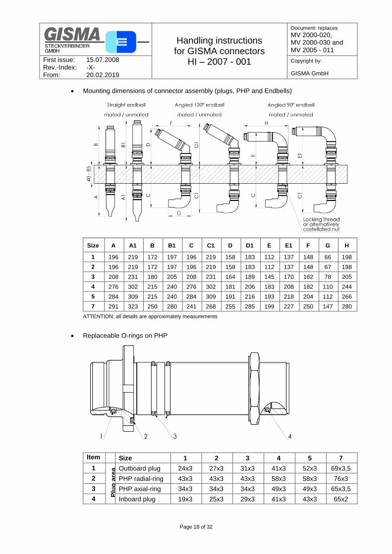
Mounting dimensions of connector assembly (plugs, PHP and Endbells)
Size A A1 B B1 C C1 D D1 E E1 F G H
1 196 219 172 197 196 219 158 183 112 137 148 66 198
2 196 219 172 197 196 219 158 183 112 137 148 67 198
3 208 231 180 205 208 231 164 189 145 170 162 78 205
4 276 302 215 240 276 302 181 206 183 208 182 110 244
5 284 309 215 240 284 309 191 216 193 218 204 112 266
7 291 323 250 280 241 268 255 285 199 227 250 147 280
ATTENTION: all details are approximately measurements
Replaceable O-rings on PHP
Item Size 1 2 3 4 5 7
1
Plu
g a
rea
Outboard plug 24x3 27x3 31x3 41x3 52x3 69x3,5
2 PHP radial-ring 43x3 43x3 43x3 58x3 58x3 76x3
3 PHP axial-ring 34x3 34x3 34x3 49x3 49x3 65x3,5
4 Inboard plug 19x3 25x3 29x3 41x3 43x3 65x2
Handling instructions for GISMA connectors
HI – 2007 - 001
Document: replaces
MV 2000-020, MV 2000-030 and MV 2005 - 011
First issue: 15.07.2008 Rev.-Index: -X- From: 20.02.2019
Copyright by:
GISMA GmbH
Page 19 of 32
Profile sealing rings
If the mounting hole is too large, O-ring 3 can be replaced by profile sealing ring. For detailed
information contact our design department.
The following tool list is necessary to mounting O-rings and profile sealing rings. In the
document MB BR22-2177 are detailed information about the mounting.
Pressure hull penetrator Profile sealing ring O-ring Tool kit
Size 1-3 Profildichtring 039 34x3 22.94.014
Size 4-5 Profildichtring 054 49x3 22.94.015
Size 7 Profildichtring 072 65x3,5 22.94.016
Size 5 hybrid Profildichtring 072 65x3,5 22.94.026
Insulator greasing
Before the initial coupling the front side of the socket connectors must be greased with
GISMA-grease EK2 (part no.: GISMA-FETT EK2), to fill the conical seal cavities with grease
(see drawing below). Greasing ensures that the two elastomer Insulators in the conical seals
can slide perfectly into its final position and thus best seal. After 20 underwater matings the
connector should be greased again.
For greasing the GISMA connectors - Grease EK2 is specified. The corresponding compatibility of this Grease is with all elastomers used in GISMA (insulating, sealing elements) given. At the same time, this product has excellent properties. The grease EK2 is not conductive. By mating the GISMA connector the contact forces applied mean the grease is completely displaced from the contact area, so that the grease does not affect the contact resistance. At the same time this ensures a high Insulation resistance - even with insertions in moist environments. Typical properties
reduced friction and wear
prevents leakage
contact oxidation resistance
neutral against plastics
Amount of grease to be used The Insulator should be greased so that the insulating sealing cone is 70-100 % filled with grease.
Handling instructions for GISMA connectors
HI – 2007 - 001
Document: replaces
MV 2000-020, MV 2000-030 and MV 2005 - 011
First issue: 15.07.2008 Rev.-Index: -X- From: 20.02.2019
Copyright by:
GISMA GmbH
Page 20 of 32
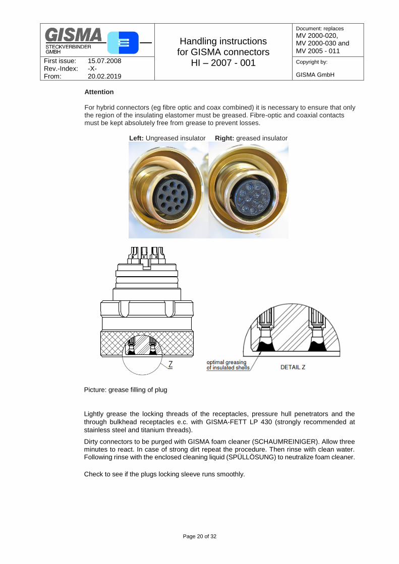
Attention For hybrid connectors (eg fibre optic and coax combined) it is necessary to ensure that only the region of the insulating elastomer must be greased. Fibre-optic and coaxial contacts must be kept absolutely free from grease to prevent losses.
Left: Ungreased insulator Right: greased insulator
Picture: grease filling of plug
Lightly grease the locking threads of the receptacles, pressure hull penetrators and the
through bulkhead receptacles e.c. with GISMA-FETT LP 430 (strongly recommended at
stainless steel and titanium threads).
Dirty connectors to be purged with GISMA foam cleaner (SCHAUMREINIGER). Allow three minutes to react. In case of strong dirt repeat the procedure. Then rinse with clean water. Following rinse with the enclosed cleaning liquid (SPÜLLÖSUNG) to neutralize foam cleaner.
Check to see if the plugs locking sleeve runs smoothly.

Handling instructions for GISMA connectors
HI – 2007 - 001
Document: replaces
MV 2000-020, MV 2000-030 and MV 2005 - 011
First issue: 15.07.2008 Rev.-Index: -X- From: 20.02.2019
Copyright by:
GISMA GmbH
Page 21 of 32
Alignment
Put the plug onto the receptacle. Twist the connector until the keyway locks into place.
While tightening the locking sleeve with the one hand, simultaneously feed in the connector
with the other.
Mating
After tightening the locking sleeve by hand, screw it onto the receptacle fitting using corresponding wrenches. If the locking sleeve is designed with a safety screw, tighten it. For defined clamping torque refer to GISMA document “Torque overview”.
Cathodic Protection
Stainless steel (1.4404/ 1.4571 comparable to 316L/316Ti), marine bronze (CW307G) or
titanium grade 5 diver mate connectors must be connected to the CP (Cathodic Protection)
system at all times. Super Duplex stainless steel connectors should be isolated from the CP
system to reduce the possibility of hydrogen embrittlement.
Maintenance
For the installation of O-rings the general guidelines for O-ring assembly have to be taken
into account. Mainly the correct installation (e.g. position), cleanness and greasing with
GISMA FETT EK2 have to be ensured.
In case, that the O-rings carrying assemblies are installed for more than 2 years to a structure
and then will be disassembled, we generally recommend to replace the O-rings.
We recommend changing the O-rings at latest after 5 years if the O-rings are used as
directed.
For assemblies, which will only be installed once, our experience shows the estimated
lifetime may be double. For operating temperatures between +5°C to +40°C, longer lifetimes
can be expected.
Defective clamps to be replaced.
The GISMA coaxial contacts must be protected to any pollution especially water / water
pressure.
Pressure testing
Series 22 plugs, receptacles and pressure hull penetrators are longitudinal watertight up to
the specified pressure range (see dimensional drawings). Every receptacles and
terminated plug for underwater applications will be pressure tested acc. Customer or
GISMA specification.
Hybrid connectors with coaxial and fibre optic contacts have to be tested with protective
caps to prevent deposits from decreasing the connectors performance!
Handling instructions for GISMA connectors
HI – 2007 - 001
Document: replaces
MV 2000-020, MV 2000-030 and MV 2005 - 011
First issue: 15.07.2008 Rev.-Index: -X- From: 20.02.2019
Copyright by:
GISMA GmbH
Page 22 of 32
7.4. SUBSEA CONNECTORS SERIES 40
The hybrid connector range series 40 is especially designed for long term subsea use under harsh
conditions, e. g. submarines. It can be supplied either singularly or as part of a harness assembly.
Series 40 connectors are only dry pluggable.
All GISMA connectors require the following acceptance tests during the terminations:
Mating test
Insulation Resistance test
High Voltage test
Attenuation test
Cable terminations can be performed on-site or offshore by GISMA trained personnel where the
cable cannot easily be moved or transported. Each GISMA connector is fitted with a pin or socket
insulator which has been tested prior to despatch.
Termination of series 40 hybrid connectors should only be undertaken by trained personnel.
All series 40 hybrid connectors must be fitted with a mating connector or a pressure watertight
protective cap prior to subsea installations. Connectors must not be energised subsea unless
coupled with a mating connector or fitted with a pressure watertight protective cap, in order to
prevent electrolytic damage to the contacts when exposed to sea water.
All mild steel sealing interfaces shall be inlayed with Inconel 625, or similar, where no additional
protection can be provided. This is to prevent localised pitting of the interface. If not possible
grease the mounting hole and the supporting surface with corrosion preventing fluid (for example
Fluid Film) as a minimum.
Stainless steel (1.4404/ 1.4571 comparable to 316L/316Ti) or titanium grade 5 connectors must
be connected to the CP (Cathodic Protection) system at all times. If the connector is designed
with a fixed flange and screw mounting, an additional CP connecting would not be required. Super
Duplex stainless steel connectors should be isolated from the CP system to reduce the possibility
of hydrogen embrittlement.
Attention: The customer is responsible for the safe operation of the connectors and cable
systems. All necessary protective measures must be taken.
NOTE: Series 40 hybrid connectors cannot be used generally for oil compensated
systems or oil compensated hose terminations. Special versions are available, please
contact our design department.
For further technical information refer to the catalogue of series 40 or special drawings.
7.4.1. Live Mate / Demate
The series 40 range of connectors are designed to be mated / de-mated with POWER OFF.
7.4.2. Protection of receptacle’s pin contacts
Under no circumstances the contacts should be exposed to seawater with power off or on. If this
situation does occur the contact surfaces of the contacts will very rapidly degrade by electrolytic
Handling instructions for GISMA connectors
HI – 2007 - 001
Document: replaces
MV 2000-020, MV 2000-030 and MV 2005 - 011
First issue: 15.07.2008 Rev.-Index: -X- From: 20.02.2019
Copyright by:
GISMA GmbH
Page 23 of 32
action. If these damaged pins are subsequently mated into a socket insert there is a very high
risk of damage to the insulation and seals within the plug.
7.4.3. Removal of Marine Growth and Calcareous Deposits
To remove calcite growth topside or subsea from GISMA connectors, a solution of 50% Citric Acid
is recommended. All seawater exposed elastomeric materials in GISMA connectors have
been fully tested against 50% Citric Acid and are compatible for duration of 1 hour. In addition,
the thermoplastic materials have good resistance to Citric Acid.
Other acid cleaners, such as >50% Acetic Acid, should not be used as they may cause
deterioration of the elastomeric materials.
Chiselling and abrasive methods are not recommended. Use of a water jet is acceptable, but the
jet should not be directed onto the pins at the front and onto any elastomer part like insulators
and boot seals.
NOTE: Keep the connector mated at any cleaning operation!
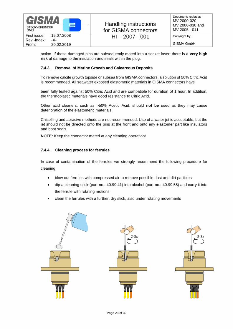
7.4.4. Cleaning process for ferrules
In case of contamination of the ferrules we strongly recommend the following procedure for
cleaning:
blow out ferrules with compressed air to remove possible dust and dirt particles
dip a cleaning stick (part-no.: 40.99.41) into alcohol (part-no.: 40.99.55) and carry it into
the ferrule with rotating motions
clean the ferrules with a further, dry stick, also under rotating movements
Handling instructions for GISMA connectors
HI – 2007 - 001
Document: replaces
MV 2000-020, MV 2000-030 and MV 2005 - 011
First issue: 15.07.2008 Rev.-Index: -X- From: 20.02.2019
Copyright by:
GISMA GmbH
Page 24 of 32
7.4.5. Connector Handling
Pre Mating Check
The connector that is to be joined must be free of dirt and foreign matter.
Lightly grease the locking threads of the receptacles and the through bulkhead receptacles
e.c. with GISMA-FETT LP 430 (strongly recommended at stainless steel and titanium
threads).
Check to see if the plugs locking sleeve runs smoothly.
Alignment
Put the plug onto the receptacle. Twist the connector until the keyway locks into place.
While tightening the locking sleeve with the one hand, simultaneously feed in the connector
with the other.
Mating
After tightening the locking sleeve by hand, screw it onto the receptacle fitting using corresponding wrenches. If the locking sleeve is designed with a safety screw, tighten it. For defined clamping torque refer to GISMA document “Torque overview for series 10 / 22 / 35 / 40”.
Cathodic Protection
Stainless steel (1.4404/ 1.4571 comparable to 316L/316Ti), marine bronze (CW307G) or
titanium grade 5 diver mate connectors must be connected to the CP (Cathodic Protection)
system at all times. Super Duplex stainless steel connectors should be isolated from the CP
system to reduce the possibility of hydrogen embrittlement.
Maintenance
For the installation of O-rings the general guidelines for O-ring assembly have to be taken
into account. Mainly the correct installation (e.g. position), cleanness and greasing with
GISMA FETT EK2 have to be ensured.
In case, that the O-rings carrying assemblies are installed for more than 2 years to a structure
and then will be disassembled, we generally recommend to replace the O-rings.
We recommend changing the O-rings at latest after 5 years, if the O-rings are used as
directed.
For assemblies, which will only be installed once, our experience shows the estimated
lifetime may be double. For operating temperatures between +5°C to +40°C, longer lifetimes
can be expected.
Defective clamps to be replaced.
Handling instructions for GISMA connectors
HI – 2007 - 001
Document: replaces
MV 2000-020, MV 2000-030 and MV 2005 - 011
First issue: 15.07.2008 Rev.-Index: -X- From: 20.02.2019
Copyright by:
GISMA GmbH
Page 25 of 32
7.5. SUBSEA CONNECTORS SERIES 80
7.5.1. General The series 80 range of connectors has been developed for long term reliable signal and low power control system applications associated with offshore installations. The subsea pluggable capacity of these connectors is achieved using pressure compensated electrical inserts employing the GISMA flushing contact principle. Connectors are usually supplied with dust caps. The dust caps must be removed prior to mating the connectors.
For further technical information refer to the catalogue of series 80 or special drawings.
All mild steel sealing interfaces shall be inlayed with Inconel 625, or similar, where no additional
protection can be provided. This is to prevent localised pitting of the interface. If not possible
grease the mounting hole and the supporting surface with corrosion preventing fluid (for example
Fluid Film) as a minimum. If the connectors are to be left unmated, in seawater, for any length of time pressure watertight protective cap must be used to protect the pin contacts in the receptacle. Over exposure will increase the risk of corrosion damage or marine growth on the contact surfaces of the receptacle’s pin contacts. This could lead to damage to the seals and insulation within the socket contacts. Plugs do not require full pressure watertight protective cap for protection. GISMA advise the fitting of POM caps to protect plugs against marine growth. It is good practice to always fit the protective cap when a connector is unmated topside prior to deployment to provide mechanical protection.
The appropriate test connector must always be used to make electrical contact during testing.
UNDER NO CIRCUMSTANCES a foreign object (such as a screwdriver, test probe, or crocodile
clip) should be used as a test connection as this could damage the seals and insulation. Such
actions will invalidate the warranty of the connector.
Attention: The customer is responsible for the safe operation of the connectors and cable
systems. All necessary protective measures must be taken.
The series 80 range of connectors can be supplied either singularly or as part of a harness
assembly. All series 80 connectors require the following during termination:
Mating test
Insulation Resistance test
High Voltage test
Continuity test
Cable terminations can be performed on-site by GISMA trained personnel or partner companies
where the cable cannot easily be moved or transported. Each series 80 connector has been
hydrostatically tested and electrically proven prior to despatch. Termination of these connectors
should only be undertaken by trained personnel.
7.5.2. Live Mate / Demate
The series 80 range of connectors are designed to be mated / de-mated with POWER OFF.
Handling instructions for GISMA connectors
HI – 2007 - 001
Document: replaces
MV 2000-020, MV 2000-030 and MV 2005 - 011
First issue: 15.07.2008 Rev.-Index: -X- From: 20.02.2019
Copyright by:
GISMA GmbH
Page 26 of 32
7.5.3. Protection of receptacle contact pins
Under no circumstances the pin contacts should be exposed to seawater with power on or off. If
this situation does occur, the contact surfaces of the pins will very rapidly degrade by electrolytic
action. If these damaged pins are subsequently mated into a socket insert there is a very high
risk of damage to the insulation and seals in the plug.
7.5.4. Removal of Marine Growth and Calcareous Deposits
To remove calcite growth subsea or topside from GISMA connectors, a solution of 50% Citric Acid
is recommended. All seawater exposed elastomeric materials in GISMA connectors have been
fully tested against 50% Citric Acid and are compatible for a duration of 1 hour. In addition, the
thermoplastic materials have good resistance to Citric Acid.
Other acid cleaners, such as >50% Acetic Acid, should not be used as they may cause
deterioration of the elastomeric materials.
Chiselling and abrasive methods are not recommended. Use of a water jet is acceptable, but the
jet should not be directed onto the shuttle pins at the front of the plug as this could result in a risk
of water being forced through the primary seals.
7.5.5. Diver Mate Connectors
Alignment
These connectors have been designed to self-align during mating. All this is required to
ensure that the alignment pin of the plug is engaged in the alignment groove of the receptacle
before pushing the plug in.
Pre Mating Check
Before mating, the receptacle connector should be checked for debris/deposits, especially
on the contacts. Prior to mating a visual inspection has to be done. Pin contacts have to be
straight and without any damages. The connectors have been designed to accommodate
sand and silt contamination; however large pieces of debris should be removed using a water
jet.
Mating
The diver mateable plug is assembled with GISMA locking system including 3 clamps and
an over-all spring and a GISMA diver handle. For mating just push the plug into the
receptacle.
Handling instructions for GISMA connectors
HI – 2007 - 001
Document: replaces
MV 2000-020, MV 2000-030 and MV 2005 - 011
First issue: 15.07.2008 Rev.-Index: -X- From: 20.02.2019
Copyright by:
GISMA GmbH
Page 27 of 32
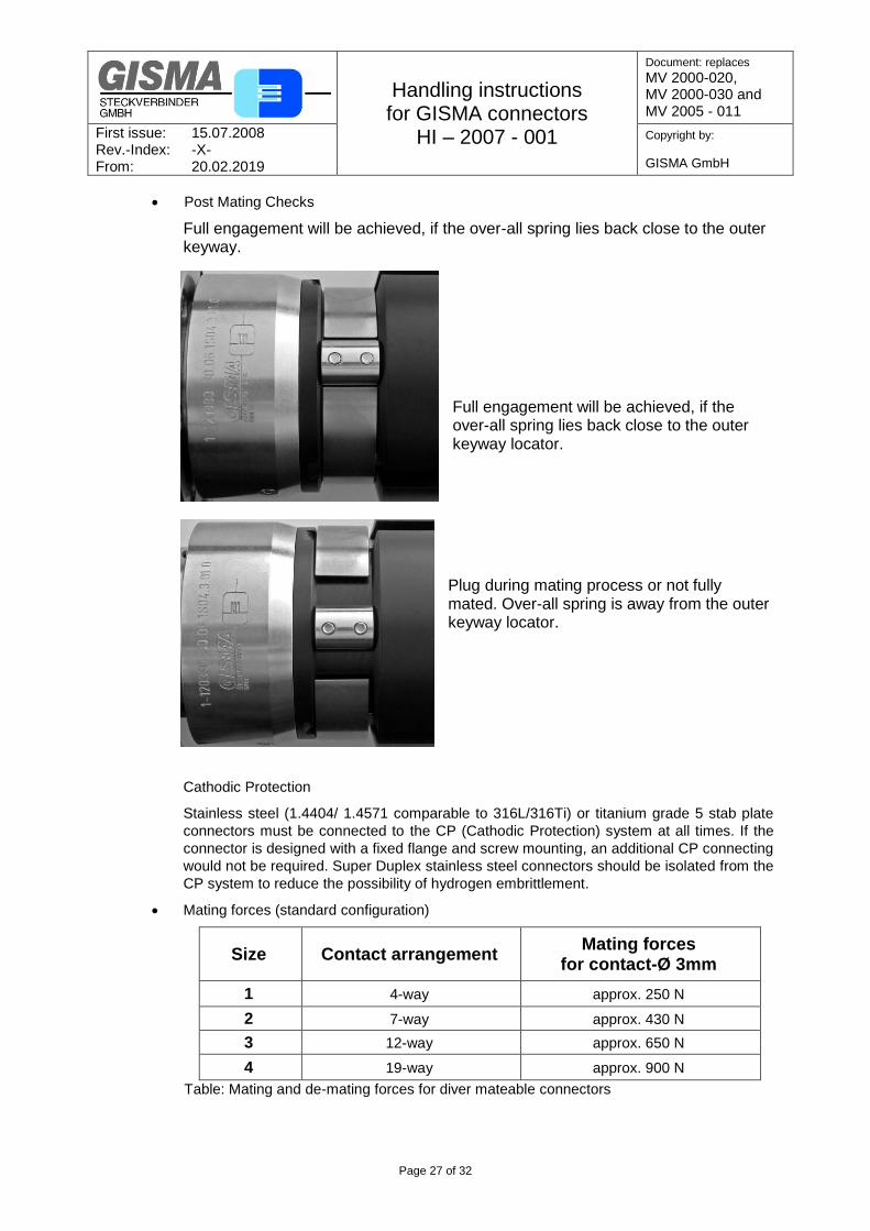
Post Mating Checks
Full engagement will be achieved, if the over-all spring lies back close to the outer keyway.
Full engagement will be achieved, if the over-all spring lies back close to the outer keyway locator.
Plug during mating process or not fully mated. Over-all spring is away from the outer keyway locator.
Cathodic Protection
Stainless steel (1.4404/ 1.4571 comparable to 316L/316Ti) or titanium grade 5 stab plate
connectors must be connected to the CP (Cathodic Protection) system at all times. If the
connector is designed with a fixed flange and screw mounting, an additional CP connecting
would not be required. Super Duplex stainless steel connectors should be isolated from the
CP system to reduce the possibility of hydrogen embrittlement.
Mating forces (standard configuration)
Size Contact arrangement Mating forces
for contact-Ø 3mm
1 4-way approx. 250 N
2 7-way approx. 430 N
3 12-way approx. 650 N
4 19-way approx. 900 N
Table: Mating and de-mating forces for diver mateable connectors
Handling instructions for GISMA connectors
HI – 2007 - 001
Document: replaces
MV 2000-020, MV 2000-030 and MV 2005 - 011
First issue: 15.07.2008 Rev.-Index: -X- From: 20.02.2019
Copyright by:
GISMA GmbH
Page 28 of 32
7.5.6. Stab Plate Connectors
Compliance
One half of a stab mate connector pair must be allowed to float so that misalignment
tolerances can be accommodated.
Mate/DeMate Speed
The connectors have been designed to operate across a wide range of mate / de-mate
speeds with POWER OFF. There is no practical limit to the speed at which the connectors
maybe mated or demated, however as a guide: -
a) Mating speed should not exceed 1 m/s.
b) Demating speed should not exceed 1 m/s.
Pre-Mating Checks
Before mating, the receptacle connector should be checked for debris. The connectors have
been designed to accommodate sand and silt contamination however large pieces of debris
should be removed using a water jet. Prior to mating a visual inspection has to be done. Pin
contacts have to be straight and without any damages.
Cathodic Protection:
Stainless steel (1.4404/ 1.4571 comparable to 316L/316Ti) or titanium grade 5 stab plate
connectors must be connected to the CP (Cathodic Protection) system at all times. If the
connector is designed with a fixed flange and screw mounting, an additional CP connecting
would not be required. Super Duplex stainless steel connectors should be isolated from the
CP system to reduce the possibility of hydrogen embrittlement.
Mating forces (standard configuration)
Size Contact arrangement Mating forces
for contact-Ø 3mm
1 4-way approx. 200 N
2 7-way approx. 350 N
3 12-way approx. 550 N
4 19-way approx. 750 N
Table: Mating and de-mating forces for stab plate connectors
7.5.7. ROV Connectors
Alignment
These connectors have been designed to self align during mating. The connectors must be
roughly aligned using the alignment keyway on the plug’s locking device and receptacle’s
main keyway slot. The mounting of the GISMA ROV handle has sufficient compliance to
accommodate fine adjustments during the final approach prior to connector engagement.
Handling instructions for GISMA connectors
HI – 2007 - 001
Document: replaces
MV 2000-020, MV 2000-030 and MV 2005 - 011
First issue: 15.07.2008 Rev.-Index: -X- From: 20.02.2019
Copyright by:
GISMA GmbH
Page 29 of 32
Pre Mating Checks
Before mating the receptacle connector should be checked for debris. The connectors have
been designed to accommodate sand and silt contamination however large pieces of debris
should be removed using a water jet. Prior to mating a visual inspection has to be done. Pin
contacts have to be straight and without any damages.
Mating
The ROV mateable plug is assembled with GISMA locking system including 3 clamps and
an over-all spring and a GISMA ROV handle (e.g. T-bar, fishtail). For mating just push the
plug into the receptacle.
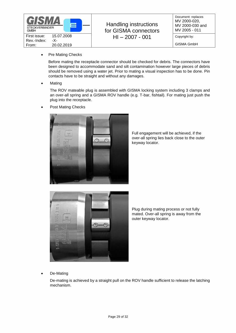
Post Mating Checks
Full engagement will be achieved, if the
over-all spring lies back close to the outer
keyway locator.
Plug during mating process or not fully
mated. Over-all spring is away from the
outer keyway locator.
De-Mating
De-mating is achieved by a straight pull on the ROV handle sufficient to release the latching
mechanism.

Handling instructions for GISMA connectors
HI – 2007 - 001
Document: replaces
MV 2000-020, MV 2000-030 and MV 2005 - 011
First issue: 15.07.2008 Rev.-Index: -X- From: 20.02.2019
Copyright by:
GISMA GmbH
Page 30 of 32
Cathodic Protection
Stainless steel (1.4404/ 1.4571 comparable to 316L/316Ti) or titanium grade 5 stab plate
connectors must be connected to the CP (Cathodic Protection) system at all times. If the
connector is designed with a fixed flange and screw mounting, an additional CP connecting
would not be required. Super Duplex stainless steel connectors should be isolated from the
CP system to reduce the possibility of hydrogen embrittlement.
Mating forces (standard configuration)
Size Contact arrangement Mating forces
for contact-Ø 3mm
1 4-way approx. 250 N
2 7-way approx. 430 N
3 12-way approx. 650 N
4 19-way approx. 900 N
Table: Mating and de-mating forces for ROV connectors
Handling instructions for GISMA connectors
HI – 2007 - 001
Document: replaces
MV 2000-020, MV 2000-030 and MV 2005 - 011
First issue: 15.07.2008 Rev.-Index: -X- From: 20.02.2019
Copyright by:
GISMA GmbH
Page 31 of 32
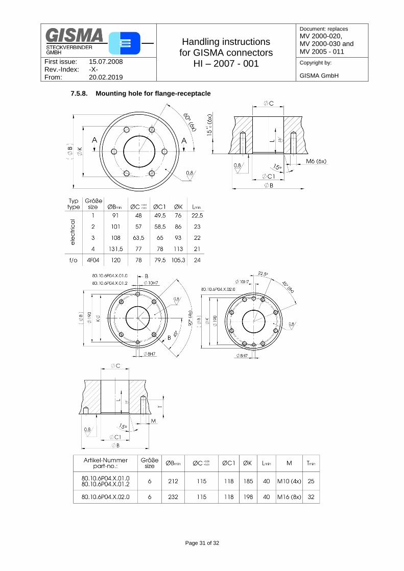
7.5.8. Mounting hole for flange-receptacle

Handling instructions for GISMA connectors
HI – 2007 - 001
Document: replaces
MV 2000-020, MV 2000-030 and MV 2005 - 011
First issue: 15.07.2008 Rev.-Index: -X- From: 20.02.2019
Copyright by:
GISMA GmbH
Page 32 of 32