Embed Size (px)
Citation preview

Handling of synthetic silica and silicate Technical Bulletin Fine Particles 28


3
IntroductionWhat are synthetic silica?What does „Handling“ mean?Handling and industrial hygieneForms supplied and ecologyForms of packaging and dispatchBag deliverySemi-bulk deliveryBulk deliveryEmptying proceduresEmptying of bagsManualSemi-automaticFully-automaticEmptying semi-bulk containersEmptying flexible intermediate bulk containers for precipitated silicaEmptying AEROSIL® fumed silica from flexible intermediate bulk containersEmptying of bulk trucks and containersConveying processesPneumatic conveyingDilute phase conveyingDune phase conveyingDense phase conveyingConveying by pumpsMechanical conveyingFurther informationConveying pipelinesElectrostatic chargingFilter systemsStorage of synthetic silica in silosDimensions and volumes of silosDischarging aidsMeasuring the extent of fillingDetermining the flow propertiesDosing of synthetic silicaGravimetric dosingContinuous dosingDiscontinuous dosingVolumetric dosingDust-free working in the factoryConventional method of workingSystems for incorporating synthetic silica into liquidsThe effect of handling on the product propertiesProduct safetyToxicology and occupational hygieneSafety engineeringEnvironmental behaviorDisposalStatutory regulations
44789
1010111112121212131313141415151616171718191919192020212223252525262728282830313131313131
11.11.21.31.422.12.22.333.13.1.13.1.23.1.33.23.2.13.2.23.344.14.1.14.1.24.1.34.24.34.44.4.14.4.24.4.355.15.25.35.466.16.1.16.1.26.277.17.2899.19.29.39.49.5
Table of contentsPage

4
1.1 What are synthetic silica? Synthetic silica in the form of silica gels have been known since the First World War, when they were used primarily as adsorption agents in gas masks. Later on they became used as drying gels. However, large-scale production of synthetic silica was unthinkable at this time for economic reasons.
After the Second World War, new manufacturing processes were developed that produced products with modified properties. New fields of application were soon found for these synthetic silica, and after a time it became necessary to produce them on an industrial scale.
Synthetic silica are classified in two groups, depending on the manufacturing process used: fumed or thermally produced silica and silicate that are produced by means of the wet pro-cess. Silicate such as SIPERNAT® 820 A are also produced by means of the wet process. These products are not mentioned separately in this publication, as they can be handled in much the same way as the precipitated silica. In other words, the equipment and methods that may be used for precipitated silica are also suitable for non-crystalline silicate. For the ACEMATT® products listed in Table 1, it is important to note that the matting effect depends on the matting agent‘s exact average particle size and particle-size distribution. Depending on the handling method used, it is possible to cause changes in the matting agent and, depending on the process manage-ment (formulation, dispersing equipment, sequence of adding substances, etc.), these changes can ultimately be discerned in the final product.
1 Introduction
Evonik Industries also produces highly dispersed aluminum oxide and titanium dioxide using the AEROSIL® process. Their respective trade names are AEROXIDE® Alu C, AEROXIDE® TiO2 P 25 and AEROXIDE® TiO2 T 805. Despite their different chemical nature, these products are also dealt with in this brochure.
Some of the characteristic technical data of fumed and precipitated silica from Evonik are compiled in Table 1. If additional properties like size of aggregates or agglomerates are needed for design of your handling equipment, please contact [email protected].
The X-ray structure of the products treated here is amorphous, with the exception of AEROXIDE® Alu C, AEROXIDE® TiO2 P 25 and AEROXIDE® TiO2 T 805. The specific density of the products – which is not included in the table – is 2 g/cm3 (exceptions: AEROXIDE® TiO2 P 25 with a density of 4.1 g/cm3 and AEROXIDE® Alu C with 3.2 g/cm3).

5
No. Trade name Manufacturing process
BET specific surface area 1[m2/g]
Tamped density 2, 4
[g/l]
Average size of agglomerates 2, 3
[µm]
1 ACEMATT® HK 125 wet 180 130 11.02 ACEMATT® HK 400 wet 200 120 6.33 ACEMATT® HK 450 wet 500 90 10.54 ACEMATT® HK 460 wet 500 85 75 ACEMATT® OK 412 wet 130 130 6.36 ACEMATT® OK 500 wet 130 130 6.37 ACEMATT® OK 520 wet 220 80 6.58 ACEMATT® OK 607 wet 130 115 4.49 ACEMATT® TS 100 fumed 250 50 9.5
10 AEROSIL® 90 fumed 90 80 *11 AEROSIL® 130 fumed 130 50 *12 AEROSIL® 130 V fumed 130 120 *13 AEROSIL® 150 fumed 150 50 *14 AEROSIL® 150 V fumed 150 120 *15 AEROSIL® 200 fumed 200 50 *16 AEROSIL® 200 V fumed 200 120 *17 AEROSIL® 300 fumed 300 50 *18 AEROSIL® 300 V fumed 300 120 *19 AEROSIL® 380 fumed 380 50 *20 AEROSIL® 380 V fumed 380 120 *21 AEROSIL® COK 84 fumed 185 50 *22 AEROSIL® MOX 170 fumed 170 50 *23 AEROSIL® MOX 170 V fumed 170 130 *24 AEROSIL® MOX 80 fumed 80 60 *25 AEROSIL® OX 50 fumed 50 130 *26 AEROSIL® R 104 fumed 150 50 *27 AEROSIL® R 106 fumed 250 50 *28 AEROSIL® R 202 fumed 100 60 *29 AEROSIL® R 805 fumed 150 60 *30 AEROSIL® R 812 fumed 260 60 *31 AEROSIL® R 812 S fumed 220 60 *32 AEROSIL® R 972 fumed 110 50 *33 AEROSIL® R 972 V fumed 110 90 *34 AEROSIL® R 974 fumed 170 50 *35 AEROSIL® R 974 V fumed 170 90 *36 AEROSIL® R 7200 fumed 150 230 *37 AEROSIL® R 8200 fumed 160 140 *38 AEROSIL® TT 600 fumed 200 60 *39 AEROXIDE® Alu C fumed 100 50 *40 AEROXIDE® TiO2 P 25 fumed 50 130 *41 AEROXIDE® TiO2 T 805 fumed 45 200 *42 SIDENT® 10 wet – 500 7.5
43 SIDENT® 22 S wet 190 90 13.544 SIDENT® 8 wet 60 350 1045 SIDENT® 9 wet 45 430 9.0
Table 1 Some characteristic data of Evonik silica and silicate
1 BET surface area, acc. to DIN ISO 9277 2 Target values 3 d50 % measured by laser diffraction acc. to ISO 13320 4 acc. to ISO 787-11 * For information regarding particle size of fumed products please contact [email protected]

6
No. Trade name Manufacturing process BET specific surface area 1[m2/g]
Tamped density 2, 4
[g/l]
Average size of agglomerates 2, 3
[µm]
46 SIPERNAT® 160 wet 170 80 1347 SIPERNAT® 22 wet 190 260 12048 SIPERNAT® 22 S wet 190 90 13.549 SIPERNAT® 22 LS wet 180 70 950 SIPERNAT® 2200 wet 190 250 6
51 SIPERNAT® 310 wet 700 95 8.552 SIPERNAT® 320 wet 180 160 16.553 SIPERNAT® 320 DS wet 180 90 7.554 SIPERNAT® 325 C wet 130 180 2055 SIPERNAT® 350 wet 55 120 4.556 SIPERNAT® 360 wet 55 180 18.557 SIPERNAT® 383 DS wet 175 90 7.558 SIPERNAT® 44 MS wet – 550 3.059 SIPERNAT® 50 wet 500 175 5060 SIPERNAT® 50 S wet 500 105 18.061 SIPERNAT® 500 LS wet 500 70 10.562 SIPERNAT® 820 A wet 95 230 7.063 SIPERNAT® 880 wet 35 260 8.564 SIPERNAT® D 10 wet – 85 6.565 SIPERNAT® D 17 wet – 150 1066 ULTRASIL® 360 wet 55 180 –67 ULTRASIL® 880 wet 35 260 –68 ULTRASIL® AS 7 wet 65 220 –
68 ULTRASIL® VN 2 wet 130 180 –70 ULTRASIL® VN 2 GR wet 130 270 5 6
71 ULTRASIL® VN 3 wet 180 160 –72 ULTRASIL® VN 3 GR wet 180 290 5 6
73 ULTRASIL® 7000 GR wet 175 270 5 6
1 BET surface area, acc. to DIN ISO 9277 2 Target values 3 d50 % measured by laser diffraction acc. to ISO 13320-1 4 acc. to ISO 787-11 5 Bulk density acc. to ASTM D1513 6 granules are described as < 10 % smaller 75 µm and > 80 % bigger 300 µm

7
Table 3 Some historical milestones connected with handling and with synthetic silica.
1.2 What does „Handling“ mean?Within the context of this brochure, the term „handling“ is understood to mean the measures and steps that have to be taken with silica in order to transport them from the production plant to the consumer‘s immediate place of use.
Handling therefore includes the choice of packaging, the means of transport to the consumer‘s plant and the storage, conveying and dosage of the product within the factory. Table 2 shows the possible operational steps involved when handling silica.
Table 2 Overview of possible steps during the handling of silica
Packag-ing/formssupplied
Transport to customer
Within the customer‘s plant
Step A Step B Conveying
Step CConveyance
Step DDosage
Bulk Road/bulk railcar/ container
Storage silo pneumati-cally, with pumps, mechanically
continuously: mechanically
discontinu-ously: mechanically, pneumatically
gravimetric volumetric
Semi-bulk FIBC Semi-bulk container, intermediate silo
Bags Pallets, loose bags
Pallets, intermediate silo
1776
about 1885
1896
about 1910
1944
about 1948
1948
about 1950
1960
1963
1967
1968
1971
1976
1978
1989
1998
1999
2000
The friction of particles is observed for the first time by COULOMB (Law of Friction)
First pneumatic conveyor
JANSSEN introduces the „disc element“ method to calculate the pressure of bulk materials
PRANTL establishes rheology as a science
Start of AEROSIL® production – the first pyrogenic silica
Suction conveyor for solids in powder form
Start of ULTRASIL® VN3 production
JENIKE develops a method of linking the properties of bulk materials with the construction of the silos
Start of conveying precipitated silica in rail and road bulk vehicles
Development of the first bag-emptying machine by the Gebrüder Grün KG
Changeover from the 5 kg bag of AEROSIL® fumed silica to the 10 kg bag
Start of SIPERNAT® production the first spray-dried silica made by Degussa AG
Start of stitched AEROSIL® bags, at the same time changeover to valve-type bags
First regular dispatch of AEROSIL® fumed silica in bulk trucks
Introduction of flexible intermediate bulk containers (FIBC) for ULTRASIL® and SIPERNAT®
Computer-controlled suction conveyor is put into operation in Degussa AG‘s pilot plant for handling techniques at the plant site Hanau
Start of delivering AEROSIL® fumed silica in FIBCs
Automatic continuous gravimetric dosing plant put into operation in Degussa AG‘s pilot plant for handling techniques located in Hanau
Online dispersing plant put into operation in Degussa AG‘s pilot plant for handling techniques located in Hanau

8
1.3 Handling and industrial hygieneFor all operational steps listed in Table 2 it is required that the handling of silica and silicate is as dust-free as possible. This is necessary in order to prevent contamination of the products as well as to comply with industrial hygiene regulations which are regulated on a regional level. Table 4 lists the maximum
acceptable average concentration limit values as stipulated by the relevant industrial safety regulations in some selected industrial countries. The quoted exposure limits relate to the respective medium concentration levels admissible during an 8-hour working day and a 40-hour working week.
Table 4 Occupational exposure limits for synthetic amorphous silica and synthetic silicates at the workplace
Germany France Great Britain USASynthetic amorphous silica
4 mg/m3 * 10 mg/m3 *5 mg/m3 **
(Poussières)
6 mg/m3 *2.4 mg/m3 **
0.8 mg/m3 *
Silicate 10 mg/m3 * 3 mg/m3 **
(General dust limit)
10 mg/m3 *5 mg/m3 **
(Poussières)
Ca: 10 mg/m3 *4 mg/m3 **NaAl: 2 mg/m3 *
15 mg/m3 *5 mg/m3 **
(PNOR = particles not otherwise regulated)
Term used AGW (Work exposure limit)
VLEP (Valeur limites d’exposition professionnelle)
WEL (Workplace exposure limit)
PEL (Permissible emission limit)
Publication AGS (Committee for Hazardous Substances) TRGS 900 (=Technical Regula-tion for Hazardous Substances) and Recommendation of the DFG (German Research Council)
INRS (Institut National de Recherche et de Sécurité)
EH40/2005 Workplace exposure limits (Health and Safety Executive)
29 Code of Federal Regulations, part1910 (OSHA = Occupational Safety and Health Administration)
Comment TRGS 900: Legal Listing Notification: Recommendation of the DFG (February 2010)
ED 984 Aide-Mémoire Technique (June 2008)
Update 10/2007 29 CFR 1910.1000 Table Z-1 and Z-3
* Inhalable dust ** Respirable dust

9
1.4 Forms supplied and ecologyAs shown in Table 5, the greatest proportion of synthetic silica is presently delivered in bags. If we disregard the percentage increase in silo dispatch, there will be little change in these figures in the next few years, considering the requirements of the industrial consumers. Bulk delivery is the most favor-able method of transport from an ecological viewpoint and, in most cases, it is the most economic as well. The large number of paper bags accumulating from this form of delivery must be disposed of. Due to the nature of the product properties, these bags can be thrown into domestic dumping sites. However, the paper bags may also be recycled using the Deinking process. In Germany the paper bag recycling is covered by Repasack (www.repasack.de).
Table 5 The dispatch of synthetic silica according to the type of packaging used, expressed as a percentage (Europe)
* Increased due to strong exports to overseas
Year Bags[%]
Semi Bulk[%]
Full Bulk (Silo)[%]
AEROSIL® and AEROXIDE®
1975 91 0 0
1988 80 0 20
1995 60 0 40
2000 50 1 49
2009 61 * 14 25
2012 45 10 45
Precipitated Silica
1975 86 5 9
1988 75 7 18
1995 59 16 25
2000 50 18 32
2009 30 20 50
2012 25 25 50

10
The following basic types of packaging are available for synthetic silica and silicate:• Dispatch of bags on pallets. In special cases, delivery may occur in the form of loose bags.• Semi-bulk delivery on pallets, for example, in FIBC (Flexible Intermediate Bulk Containers) with a usual capacity of 2 m³.• Bulk delivery in bulk trucks or silo containers. Bulk railcars or 20 ft, 30 ft and 40 ft ISO box containers with inliner may be used in rare cases. 2.1 Bag deliveryA multi-layer valve paper bag is generally used. Its exact construction must be designed to meet the requirements of the product of interest during transport and storage (see Figure 1). The bag‘s dimensions, paper quality, number of layers, and any coatings or intermediate layers serving as moisture protection are the major variables. Today, most bags are shipped on pallets. The dimensions of the pallets are designed to fit the bag and the means of transportation. Transportation safeguards, such as stretch- or shrink-wrapping the pallets, covering the bags, further improve safe transport. Indeed, complete shrink-wrapping also helps provide some protection against the weather.
2 Forms of packaging and dispatch
The silica from Evonik are used worldwide in a wide range of applications. In order to maintain the specific properties of the products, appropriate packaging must be available to suit the amount of silica and the method of processing used. Since there have recently been many advances in the types of pack-aging that take these aspects into consideration, we will first provide a brief overview of the various packaging options. You can find a detailed description of the different forms of packaging and what products go in what packaging under the corresponding Technical Information. These Technical Information sheets can be updated more quickly, enabling us to keep up with continuing developments in the packaging industry. Please request our Technical Information TI 1232, “Types of Packaging for precipated silica” or Technical Information TI 1231, “Types of Packaging for AEROSIL® and AEROXIDE®”.
Figure 1 Typical bag packaging of Evonik AEROSIL® products and precipitated silica

11
2.2 Semi-bulk deliveryThe FIBC (Flexible Intermediate Bulk Container) has become the dominant semi-bulk container for shipping synthetic silica (see Figure 2). Also known as „Big Bag®“ or „Super Sack®“, these flexible containers have a capacity intermediate between the bags described in Section 2.1 and the bulk vehicles described in 2.3. FIBC made of woven plastic-coated bands and specially sealed seams have proven successful. Depending on the product, the containers may have special built-in features that provide extra stability. Depending on both the product and operational area, the FIBC may also be designed with derivation ability for electrostatic charges. As described under Section 3.2, methods for emptying FIBC can differ, depending on the product. FIBC may also be shipped shrink-wrapped, as already described for bag delivery on pallets.
2.3 Bulk deliveryBulk delivery is the most economical alternative. Depending on the amount ordered and storage room available at the customer‘s end, this method of delivery provides the optimum solution regarding economical and environmentally friendly packaging and transport (see Figure 3).
The main advantages are:• minimal generation of dust during processing, making it possible to observe dust limit values,• movement of large amounts with a minimum of personnel,• reduction of packaging costs,• no disposal of packaging material and pallets,• no negative effects on the product properties during transport,• minimum floor space required for storage, • good starting basis for further processing.
A corresponding storage silo must be available in order to accommodate the bulk delivery (see Sec. 5.1).
Bulk trucks currently have a volume of approx. 66 m³ and can hold between 4 and 18 metric tons, depending on the product (see Technical Information 1231 and 1232). In rare cases bulk trucks with higher volumes can be used.
Figure 2Example of a FIBC (Flexible Intermediate Bulk Container)
Figure 3Example of a bulk truck used for AEROSIL® fumed silica and precipitated silica

12
3.1.2 Semi-automatic A variety of different types of semi-automatic bag-emptying equipment are available on the market. They differ from one another in their operating principle or even quite fundamen-tally in their degree of automation. For example, the bag-emp-tying unit illustrated in Figure 5 is already largely automatic. The cutting open and emptying of the bags as well as the compaction of the empty bags is fully automated. Feeding the bags into the unit is the only manual part of the operation.
The bag is placed onto a platform inside the machine. The emptying process is then started by pressing two push-buttons (necessitating two-handed operation). The door of the machine closes and the bag is cut open by a rotating knife, which is mounted on a swivel arm. The platform subsequently folds out into two sections, with the bag secured by spikes that have already pierced the bag at that stage. The bag is emptied by the shaking action of the platform sections. If necessary, a fluidizing air stream can be passed through some of the spikes. After the emptying process is complete, the spikes are withdrawn and the bag dropped and fed into the compacting unit.
It is, however, also possible to use less automated emptying units for silica bags. There are, however, some fundamental factors that must be considered.
3 Emptying procedures
3.1 Emptying of bags 3.1.1 ManualSimple equipment to enable the virtually dust-free emptying of bags may be easily constructed by internal workshops. A particularly simple version consists of an extraction hood that is fixed to a funnel-shaped base and connected to a suitable exhaust system. The lower part contains a bar grid onto which the bag is placed and then cut in half with a blade. Before the two halves are emptied, the exhaust hood is closed off with a flexible dust curtain to prevent dust from escaping.
About 15 – 20 bags per hour can be emptied using this method. The emptied bag halves are rolled together while still in the hood and are then passed through an opening in the side into a refuse bag attached there. The lower part of the emptying equipment leads to a storage hopper from where the product can be conveyed directly to the processing unit or to an intermediate or day silo. This simple version of a bag emptying device can be shown together with other bag emptying equipment in the handling pilot plant at the Evonik site in Hanau.
Other simple devices as shown in Figure 4 are also purchas-able. However, it is important that the activities of cutting open the bag, emptying it, and rolling or folding up the empty bag take place within an enclosure that is exhausted by suction and sealed as tightly as possible.
Another manual method consists of emptying bags that are open only at the top by means of a suction pipe (see Figure 29). The latter is attached to a suction conveyor or an air-driven diaphragm pump (see 4.1 and 4.2). Great care must be taken not to simply dip the suction pipe into the product. Instead, the pipe should be moved back and forth over the whole sur-face. This method is not dust-free, however, because dust is created on opening the bag and on disposal of the empty bag.
Figure 4Manually operated bag-emptying device
Figure 5Semi-automatic bag-emptying machine (Manufacturer: Dinnissen B. V, 5975 NB Sevenum, Netherlands)

13
The finer the product discharged, the more important it becomes for the machine to be almost completely sealed during the emptying process. If the unit cannot be completely closed while the bag is being emptied, care must be taken that any opening is no larger than strictly necessary and that the dust extraction facilities are perfectly satisfactory. All types of equipment should be fitted with an automatic self-cleaning filter possessing an appropriate surface area for the volume of air and the product characteristics.
It has already been explained in Section 3.1.1 that it is also important for the first stage of the bag disposal to be fully integrated within the machine. Irrespective of whether the bags are manually folded or conveyed into a bag compaction unit, it is essential for the operation to be carried out within the equipment (i. e., in the dust extraction area), since considerable amounts of dust can also be generated at this stage. 3.1.3 Fully-automaticAs already indicated in Section 3.1.2, there is a large variety of bag-emptying equipment ranging from semi-automatic to fully automatic units. At this point it is appropriate to give an example of the kind of machine suitable for handling very large quantities of bags. These types of unit are usually fitted with de-palletization and bag separation facilities and conveyor belts. It then only requires a forklift truck to place the com-plete pallet onto a specially designed platform. The following stages are all fully automatic. After conveying the bag into the machine, illustrated in Figure 6, the bag passes several rotating blades, which cut it open in a lengthwise direction. The opened bag then reaches a rotating drum, where it is emptied. The silica flows into an outlet funnel, from where it is immediately discharged. The empty bag passes through the drum by way of a removal shaft to a compaction unit or to a bale press. The use of such equipment is viable only when throughput is high.
3.2 Emptying semi-bulk containersFIBC‘s, which Evonik uses as semi-bulk containers, are emptied in many different ways, depending on the product. Precipitated silica and even AEROXIDE® TiO2 P 25 and AEROXIDE® TiO2 T 805 are conventionally emptied by gravity discharge (see Sec. 3.2.1). On the other hand, a special discharging device has been developed for AEROSIL® and some fine particle SIPERNAT® products, enabling it to be conveyed directly out of the FIBC (see Sec. 3.2.2). 3.2.1 Emptying flexible intermediate bulk containers for precipitated silicaThe flexible intermediate bulk containers used by Evonik and described in Section 2.2, TI 1231 and TI 1232, are fitted with a discharge spout in the center of the base (see Figure 7). For emptying, the bag is suspended above the container to be filled, which should be equipped with an extraction system. The material flows out freely when the outlet pipe is opened. For some products, it is necessary to subject the bag to mechanical agitation to prevent bridging and ensure that the FIBC will be emptied steadily and completely. If the container is hung up in such a way as to serve as a weighing vessel, it is also possible to calculate the dosage by loss-in-weight measurements.
Before the empty bag can be disposed of, it has to be folded to a size that may be easily handled. The dust generated here should be kept to a minimum by the use of suitable equipment. Some fine particle sized SIPERNAT® grades are offered in FIBC which require the discharging process described in 3.2.2.
Figure 6Cross-section of a fully automatic bag-emptying machine (Manufacturer: Schüttguttechnik Borgner & Partner GmbH, 63697 Hirzenhain, Germany)
Figure 7Discharge of precipitated silica from an FIBC(Manufacturer: Hecht Technologie GmbH, 85276 Pfaffenhofen, Germany)

14
3.2.2 Emptying AEROSIL® fumed silica from flexible intermediate bulk containersAs already mentioned in Section 3.2, a special discharging device was developed to empty AEROSIL® fumed silica from FIBC‘s. This Powder Emptying System (known as PESy) allows the FIBC to be connected directly to the conveyor, dust-free. Double-diaphragm pumps operated by compressed air and even pneumatic suction conveyor systems come into consideration for the latter (see Sec. 4). But the PESy can also be connected directly to a self-priming processing device, such as the Ystral Conti TDS (see Sec. 7.2). The PESy is inserted into the matching outlet on the FIBC, either by hand or as part of an emptying station. It is then fastened by a Velcro strip and sealed (see Figure 8). Only then is the FIBC opened. The PESy permits the contents of the FIBC to be fluidized, thereby making the AEROSIL® fumed silica free-flowing. The silica can now be conveyed from the bag directly. The precise method and more details about using the PESy can be found in the Technical Information 1219. As mentioned in Section 3.2.1. some fine particle sized SIPERNAT® grades are offered with PESy as well. Detailed information on grades and precise description of the discharging method can be found in the TI 1321.
3.3 Emptying of bulk trucks and containersThe discharging of bulk trucks and silo containers assumes that a storage silo is available at the customer‘s end. Data about the silo‘s size and design can be found in Section 5.
The discharging of bulk trucks and the conveyance to the customer‘s storage silo are normally carried out pneumatically. The vehicles are equipped with a compressor for generating the conveying air, but can also be connected to plant air. Depending on the product, the vehicle‘s container is pres-surized anywhere between 0.5 to 1.5 bar during discharge. It also feeds air into the conveying line. For some products, a fluidizing bottom in the discharge cone is employed to improve the product‘s flowability. When it becomes neces-sary to feed plant air, the compressor needs to supply a flow of conveying air equal to 8 – 10m³/min at 1.5 bar.
When the bulk truck is tilted during the emptying process, approximately 10 meters of lifting clearance must be available.The product pipeline is connected by means of a coupling with a nominal width of 100 mm to comply with DIN 14309 or 14323 for pipes and hoses, respectively. When plant air is fed into the conveying system, then the connection is made by means of a coupling with a nominal width of 50 mm to comply with DIN 14307 or 14321 for pipes and hoses, respectively.
Discharge lasts between 45 and 90 minutes, depending on the silica. For some ULTRASIL® GR grades the gravity discharge of the bulk truck might also be an option. In that case a conveying system (mechanically or pneumatically) at customer’s side is mandatory.
Figure 8 Discharge of precipitated silica from an FIBC

15
4 Conveying processes
4.1 Pneumatic conveying The following statements should serve as general information. Customers are advised to make use of any experience offered by respective suppliers before investing in new equipment.
We differentiate according to the solid-to-air ratio: • Low solid-to-air ratio for dilute and loose phase conveying with a conveying speed of approx. 20 – 40 m/s. This kind of pneumatic conveyance is suitable for most bulk materials. The solid-to-air ratio of 5 kg/kg air is not generally exceeded. Suction and pressure conveying systems can be used here. Suction conveying is the oldest pneumatically operating conveyor system. Figure 10 shows a pilot plant for pneumatic/suction conveying systems.
• Intermediate solid-to-air ratio operates at conveying speeds of approx. 10 – 20 m/s. This kind of pneumatic conveyance intentionally causes deposits to be formed in the pipeline, deposits that are continuously refluidized. The expression dune phase conveying is also used for this reason. The solid-to-air ratio lies between approx. 5 and 10 kg/kg air.
• High solid-to-air ratio for the dense phase conveying of granulated (and powdered) bulk materials with a solid-to- air ratio in excess of 20 kg/kg air. Designed as low velocity conveying systems, these units operate at air velocities of 2 – 10 m/s.
Generally speaking, pneumatic conveying systems offer the following advantages over systems of mechanical conveyance:• space-saving and flexible installation options, even when retrofitting• low total costs (see Figure 9)• automatic removal of residues from the pipeline by afterblowing, of importance, for example, when changing products• dust-free operation, meaning no environmental impact• few mechanically operating parts• low noise pollution if a suitable conveying air device has been installed There are several kinds of pneumatically operating conveyor systems and the distinctions between them are not always clear-cut. The authors have attempted to compare the well-known methods in Table 6. The standard terms used are com-piled in Table 7, which is divided into the same basic columns as Table 6.
Figure 9 Comparison of total costs incurred with pneumatic and mechanical conveying equipment as a function of time
1
0
2
3
cost
s
pneumatical conveying mechanical conveying
1 2 3 4 5 6 7 8 9 10years
Figure 10Pneumatic suction conveying system in the Handling Pilot Plant in Hanau

16
The different kinds of pneumatic conveyance available are illustrated in Figure 11. As mentioned above, the boundaries between the named procedures are not easily defined, since some overlap is possible. The choice of process depends, among other things, on the material to be conveyed.
High solid-to-air ratio should be used in particular when this is granulated material or spray-dried silica with a standard-ized fine dust content, because dense phase conveying causes far less particle destruction than, for example, dilute phase conveying. The damage to the substance being conveyed becomes less as the solid-to-air ratio increases. This is also reflected in the respective air velocities (see Table 6). The main thing to observe is that all silica manufactured by Evonik can be conveyed pneumatically when suitable systems are used.
4.1.1 Dilute phase conveyingThis process operates using high air velocities and is therefore particularly suitable for cohesive products in powder form (e. g., AEROSIL® fumed silica). The materials are well fluidized by the large amounts of air, and their flow properties are improved as a result.
We differentiate between two principal methods: pressure conveying and vacuum conveying. The latter is also known as suction conveying. Pressure conveying involves the use of excess pressure to send the conveying stock through the pipeline. The blower is thus situated in front of the feed inlet. Conveying distances of up to approx. 250 m are possible using this method.
Suction conveyors operate by means of an apparatus used to create a vacuum, for example, a vacuum pump, situated at the end of the conveying pipeline. However, it is recommended that customers use this method for silica only for distances of up to 60 m, for example, for transport within the factory in Step C of Table 2. 4.1.2 Dune phase conveyingDune phase conveying too can be used to transport substances with poor flow properties. As shown in Table 6, this method requires a higher degree of fluidization than dense phase conveying, which is discussed in Section 4.1.3. A maximum conveying distance of 300 m is given for this method of con-veyance. The hourly conveying capacity can amount to several tons over such a distance.
Figure 11 Pneumatic conveying. Schematic diagram of dilute phase conveying (top); dune phase conveying (middle) and dense phase conveying (below)
Table 6 Literature data common in chemical industry for dilute phase, dune phase and dense phase conveying
Table 7 Overview of pneumatically operated conveying procedures and a selection of trade names used by well-known manufacturers
Solid-to-air ratio Low Intermediate High
Air Velocity [m/s] 20 – 40 10 – 20 2 – 10
Relative velocity of product (relative to air velocity) [%] 85 – 95 80 – 90 50
Solids loading ratio[kg
Product/ kg air] 2 – 3 5 – 10 > 20
Suction/pressure unit
Suction/ Pressure unit
Pressure unit
Pressure unit
Pressure range – 0.5 – +0.5 0.5 – 1.0 1 – 6
Solid-to-air ratio Low Intermediate High
Term used for method of conveyance
Dilute phase conveying Loose phase conveying
Dune phase conveyance Dilute phase conveying
Dense phase conveying Plug flow convey-ing Low velocity conveying
Known under trade name
Vac-U-Max Fluid-FlexFluid-Lift
Fluidschub Fluidstat Pneumosplit Pneuoschub Taktschub Over Flow system

17
4.1.3 Dense phase conveyingAs mentioned above, dense phase conveying is advanta-geously used in practice for the transport of granulated silica. According to manufacturer‘s data, this conveying system is the gentlest method of pneumatically conveying products, despite the very high investments involved. Dense phase conveying is very safe. Even if the unit is switched off when fully charged, for instance due to a power cut or breakdown of the compres-sor, no problems arise, because the conveying process is able to set itself in motion again. Blockages do not occur in the conveying pipeline if engineering design is correct.
Conveying distances of up to several hundred meters are pos-sible using dense phase conveying. However, the conveying capacity decreases as the conveying distance increases. Carefully directed blasts of secondary air at different sections in the pipeline make it possible to use dense phase convey-ing equipment for products with poor flow properties, for example, the Pneumosplit or Fluid-Schub processes (see Figure 12).
Wear to pipelines or to right-angle bends in the pipes is negligible when conveying silica. The degree of breakage of granulated materials is low with this conveying process. Particle destruction increases approx. to the third power of the particle conveying velocity. Flexible pipes can also be used for dense phase conveying.
4.2 Conveying by pumpsDespite being based on a pneumatic process, pump conveying was not discussed in Section 4.1. This is because the diaphragm pumps used for this purpose bring about the „pneumatic“ transport by means of mechanically operating parts in the product flow.
If, for technical reasons, only small amounts of conveying air are desired, the customer is generally recommended to use diaphragm pumps driven with compressed air for the transport of synthetic silica, which have good air-retaining properties. By introducing small quantities of air into the synthetic silica, the silica, which are prone to bridging, are converted into a liquid-like flowing state.
Compressed-air driven diaphragm pumps have proven them-selves to be very suitable for conveying fine particle synthetic silica. This is due to the relatively low conveying speed of 3 – 5 m/s.
The self-priming diaphragm pumps are not sensitive to run-ning dry and are relatively easy to handle. They operate at a pressure of 3 – 8 bar; the compressed air does not come into contact with the conveying stock. Conveying capacities of up to 800 kg AEROSIL® 200 or 1000 kg of SIPERNAT® 22 S per hour are possible (with pump DN 80 / 3 inch) while achieving a height of 30 m. However, the conveyable distance varies depending on the type of silica.
Figure 12 Dense phase conveying system for granulated silica
18
Figures 13 and 14 show different models of such diaphragm-type pumps, which are suitable for the transport of silica.
An excess air valve or „snifter valve“ should be inserted prior to suction from closed containers or when conveying synthetic silica that are not easy to fluidize. The excess air causes an additional loosening of the silica in the pump chambers. The pump chambers can be directly supplied with fluidizing air to prevent blockages when especially problematic sub-stances are being conveyed. In special cases peristaltic pumps can be used as well, but these are mostly low capacity and low air applications.
Other kinds of pumps may also be used to convey substances in powder form. However, we are unable to recommend these pumps, because the applicational properties of the silica can be changed by the considerable mechanical stress involved.
4.3 Mechanical conveyingHistorically speaking, the oldest method of transporting bulk materials within the works is the mechanical conveying with belts, screws and bucket conveyors. Despite the advantages of pneumatic conveyance described in Section 4.1, there are individual cases where special requirements make mechanical conveying preferable.
The so-called Z-bucket conveyors (see Figure 15) and con-veyor belts are used, for example, when a product needs to be conveyed especially gently. This is the case, for instance, when granulated products are to be handled with as little abrasion and breakage of the granules as possible.
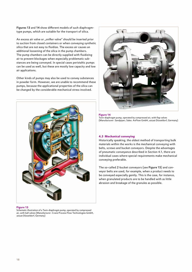
Figure 13 Schematic illustration of a Twin-diaphragm pump, operated by compressed air, with ball valves (Manufacturer: Crane Process Flow Technologies GmbH, 40549 Düsseldorf, Germany)
Figure 14 Twin-diaphragm pump, operated by compressed air, with flap valves(Manufacturer: Sandpiper; Sales: AxFlow GmbH, 40549 Düsseldorf, Germany)

19
Conveyor screws, which are generally used for short, horizon-tal stretches or those with a slight gradient, should only be applied as closed-flight progressive screws and with a filling degree of 50 % maximum. Experience has shown that pipe conveyor screws with a spiral profile are less suitable for silica.
4.4 Further information
4.4.1 Conveying pipelinesWhen choosing pipelines for conveying synthetic silica, the main consideration is the effective removal of electrostatic charging (see 4.4.2).
The roughness of the walls and abrasion are of secondary importance. Under normal conveying conditions, synthetic silica cause practically almost no abrasion in the pipeline. The use of aluminum or stainless steel pipes is recommended for the reasons mentioned above.
If flexible tubes are required, pipes with incorporated conduc-tive band must be used. All joints, inspection glasses and the like must be bridged over, and the entire conveying unit must be grounded (see Figure 16).
4.4.2 Electrostatic chargingSynthetic silica have very good insulating properties. For this reason, tremendous electrostatic charges can build up when conveying these products, particularly at very high speeds (see also Technical Bulletin Pigments No. 62: Synthetic Silica and Electrostatic Charging). Hazards connected with static charges of this nature, for example, flying sparks, can be avoided by grounding the entire conveying unit (see 4.4.1). Care must be taken to ensure that the grounding or equaliza-tion of potential are not interrupted anywhere along the line (e. g., at connections or inspection points) (see Figure 16).Detailed information on this topic are given in the Technical Bulletin No. 62 “Synthetic Silica & Electrostatic Charges”.
4.4.3 Filter systemsAfter the pneumatic conveyance, the conveying air and the silica must be separated. Since cyclones may only be used as preliminary separators with a few precipitated silica, it is mainly self-cleaning filters that are used here. Self-cleaning filters are understood to mean filtering separators whose filter medium, which is covered in dust particles, is periodi-cally regenerated, that is, cleaned (see Figure 17). This filter medium is generally in the form of tubular or bag filters. As a rule, the tubular filters are somewhat more effective than the bag filters.
Figure 16 Well grounded joint of a pipe used to transport silica
Figure 15 “Z”-bucket conveyor for the gentle transport of synthetic precipitated silica in granulated form (Manufacturer: Nerak GmbH, 29313 Hambühren, Germany)

20
With silica, the cleaning must be carried out using compressed air that is regulated by differential pressure or by time impulses. The filter media are generally made of felt that may also be coated. Mechanical cleaning cannot be recommended.
When calculating the size of such filtering separators, the specific filter area load factor of 0.3 to 0.5 m3 x m-2 x min-1 for AEROSIL® fumed silica and 0.5 to 1.0 m3 x m-2 x min-1 for pre-cipitated silica (depending on the particular grade) must not be exceeded. It should also be considered that the conveying of silica is accompanied by a loosening up, that is, a decrease in the bulk density, of the material. The volume of separators or receiving hoppers should be calculated generously with this in mind (compare Sec. 8).
Conveying with air-driven diaphragm pumps also causes air to be transported which must then be separated from the product. Even when this kind of pump is used for conveying, a separator must be installed. However, the latter can be correspondingly smaller than those required with pneumatic conveying, due to the considerably reduced amounts of air.
5 Storage of synthetic silica in silos
5.1 Dimensions and volumes of silos Synthetic silica are generally stored in tall cylindrical silos with axial symmetrical hoppers (see Figure 18). The majority of these are made of aluminum alloys (AlMg3 or AlMg2.5) or stainless steel (1.4571). Practice has shown that a hopper with an angle of inclination of 30° – 60° to the horizontal (depend-ing on the grade of silica) is adequate, provided that suitable fluidizing equipment is installed. Hence, it is also possible to completely empty the storage silo. Tests on the flow proper-ties of synthetic silica have demonstrated that the internal angle of friction is generally so high that practically non-realizable values result when calculating the silo hopper and discharge outlet for mass flow (see Sec. 5.4).
Figure 18 Storage silo for synthetic silicaFigure 17 Filtering separator / jet-filter

21
The necessary silo volume for deliveries of synthetic silica is decided by the following points:• form of delivery,• consumption,• structural factors,• loosening up caused by unloading.
The fact that a certain reserve of silica must remain in the silo to ensure that production can continue unhindered, should also be taken into consideration. The minimum volumes given in Table 8 should therefore be increased as necessary to allow for high consumption. This is the only way to ensure that no problems will occur during operation .
Table 8 Suggested minimum silo volumes required for storing synthetic silica at customer site
5.2 Discharging aidsAs mentioned in Section 5.1, the corresponding geometry of a silo is not sufficient to ensure a problem-free discharge of material from the silo. Hence, emptying aids are essential. The following devices have proved successful in practice for synthetic silica:• fluidizing cone• compressed air jets (flow pads)• segmented base
These conveying aids have one thing in common. They enable air to be passed into the silica near to the outlet either continuously or in impulses. This causes a fluidization of the product; that is, the flow properties are improved in such a way as to guarantee problem-free discharging from the silo (see Figure 19).
The fluidizing cone is installed in the lower part of the silo hopper, whereas the segmented base covers the entire silo hopper. In both systems, the air is introduced through fabric or sinter plastic that is permeable to air (see Figure 20).
Material Kind of delivery Minimum silo volume m3
Precipitated silica Bulk truckBulk railcarContainer
100 1 – 150 2
160100
AEROSIL® fumed silica Bulk truck 150
Figure 19 Demonstrating the flow properties of synthetic silica being discharged from a silo containing a fluidizing base as an emptying aid
Figure 20 Interior view of a fluidizing device: look inside a TURBO-KONUS (Manufacturer: AZO GmbH & Co. KG, 74706 Osterburken, Germany)
1 Granules 2 fine particle products

22
However, the surface of the segmented base is-as the name suggests-divided into several parts, and each of these seg-ments can admit air individually. The simplest discharging aids from a technical point of view are the compressed air jets (see Figure 21). These are special nozzles that are spread out evenly over the silo hopper.
Finely divided synthetic silica such as AEROSIL® fumed silica are preferably emptied using segmented bases. Fluidizing cones and fluidizing jets (operating in impulses) are suitable for silica grades with coarser particles, for example, ULTRASIL® VN 3 or SIPERNAT® 22.
Nevertheless, the inclination of the silo‘s discharge cone and the emptying aids must be chosen to suit the particular grade of silica. It should be noted that these discharging aids cause a loosening up or fluidization of the product; that is, the bulk density is reduced (see Sec. 8).
Mechanically operated discharging devices, on the other hand, threaten to compact the finely divided silica, and cannot be recommended for this reason. An exception are those systems, which feed the silica into the outlet with the assistance of a „scraper“.
5.3 Measuring the extent of fillingA variety of systems may be used for measuring the filling level of synthetic silica in storage silos. The possible systems must be individually chosen to suit the different kinds of synthetic silica. Gravimetric measuring gives a continuous indication of the extent of filling. For this purpose, the silo is installed on top of load cells that constantly record the weight of the silo, includ-ing its content. Depending on the method and place of instal-lation, up to four of these load cells are required for a silo. It is not possible, or at least difficult, to fit load cells subsequently to existing silos for mainly structural reasons. It is, however, sometimes possible to fit strain gauge stripes at a later stage, but these do not normally provide the same level of accuracy as load cells.
Another continuous measurement method to consider is the use of ultrasonic techniques. However, the suitability of this method largely depends on the type of silica that is, its bulk density. With some silica, the current limits of available instru-mentation is reached.
One of the discontinuous methods of measuring the filling level involves hanging a special motor-driven plumb line and bob into the silo. The extent of filling is determined by mea-suring the length of the plumb line. This system only functions when the product in the silo is not being fluidized, that is, not during charging and discharging.
Final values can be obtained by using devices that react to the damping of vibrations or movements. Rotary paddles are generally used for precipitated silica. The size of the paddle, however, depends greatly on the product involved and on the strength of the fluidization. So-called vibration fork probes are the best option for AEROSIL® fumed silica (see Figure 22). It should be observed that the sensitivity is specially adjusted to suit the pyrogenic silica. Vibrating bars are another possible option for granulated silica.
Figure 21 View of a fluidizing jet: (Manufacturer: Solimar Pneumatics, Minneapolis, MN 55432, USA)

23
Figure 24 Graph for interpreting mass flow, which shows the wall friction angle ϕx as a function of the inclination of the hopper wall. Parameter for the series of curves is the effective angle of friction ϕe
5.4 Determining the flow propertiesPowdered and granulated materials have very different flow properties. The majority of flow-related problems occurring in practice are connected with the kind of flow profile in the silo. The flow profile describes the way in which bulk materi-als flow within the silo.
We differentiate here between „mass flow“ and the unde-sired „funnel flow“ (see Figure 23). Mass flow means that the entire contents of the silo are set in motion as soon as the bulk material is discharged. No dead zones are formed and the bulk material flows along the wall of the hopper. On the other hand, funnel flow occurs when the bulk material only flows from a central zone, thus forming an outflow funnel surrounded by dead zones on the periphery. In addition to bridging and bonding, funnel flow can also bring about the unwanted shaft formation („piping“) where the bulk materials only flow through a central pipe, making complete removal impossible.
A number of factors determine whether mass flow or funnel flow occurs in a silo:• the inclination of the hopper wall Θ, measured to the vertical,• the shape of the hopper (conical or rectangular),• the wall friction angle between the bulk material and the wall material ϕx and• the effective angle of friction ϕe.
The limits between mass and funnel flow, which result from the mathematical solution of the stress field in the hopper, are plotted in Figure 24 for the conical-shaped hopper (axial symmetrical stress field).
Figure 22 Vibrating fork probe suitable for measuring the extent of filling of AEROSIL® products (Manufacturer: UWT GmbH, Level Control, 87488 Betzigau, Germany)
Figure 23 Illustration of mass and funnel flow. Details are given in DIN 1055, part 6

24
The angles of friction ϕx and ϕe can be measured with shear-ing equipment or powder rheometers. The best-known of these are Jenike translation shear device and the Schulze Ring shear Tester. The values obtained from this measurement can also be used to calculate the diameter of the discharge outlet needed to prevent bridging. Since the decision as to whether mass or funnel flow occurs depends mainly on the wall fric-tion angle ϕx, at least the walls of the hopper area should be made of a suitable material that demonstrates a low wall friction angle. From a rheologist‘s point of view, plain metal surfaces are generally better than coated ones as regards the flow behavior.
Table 9 gives the values measured with a selection of products for the angles of friction mentioned. The wall friction angle ϕx is only marginally smaller than the effective angle of fric-tion ϕe. This makes it practically impossible to build silos with a mass flow, because the inclination of the hopper Θ would need to be in the range of 0° – 15°. Since this cannot be techni-cally realized, funnel flow silos are generally built. Discharging aids or emptying appliances with a large feed pro-file are installed to prevent shaft formation. If shaft formation occurs, the danger of „flooding“ increases.
Table 9 Technical Data of certain Evonik bulk material products determined using the Jenike apparatus (acc. to J. Schwedes). Θ is the maximum inclination of the discharge hopper to the vertical at which mass flow can still be achieved. d is the minimum diameter of the discharge outlet with which bridging can be prevented without the use of additional aids; D is the corresponding diameter required to prevent shaft formation in a funnel flow silo. ϕx is the wall friction angle between the bulk material and the wall material, ϕe is the effective angle of friction that gives the internal friction of a bulk material during stationary flow
The flow functions of the amorphous silica and the crystal-line silicate SIPERNAT® 820 A listed in Table 9 are plotted in Figure 24. The flow function of SIPERNAT® 22 is very flat and almost runs through the origin of the coordinate system. Even at higher consolidating pressures, the compressive strength of the bulk material does not increase over-proportionally; that is, SIPERNAT® 22 demonstrates excellent flow proper-ties and very little tendency of bridging. This is not the case with AEROSIL® 200. An increase in consolidation pressure causes a slightly over-proportional rise in the flow function of this silica. Since the bulk density of AEROSIL® 200 is also extremely low, relatively large outlet diameters d are calcu-lated to prevent bridging (d is inversely proportional to the bulk density). Furthermore, AEROSIL® 200 demonstrates an extreme consolidation over time, see Table 9.
Θ d[m/m]
D[m/m]
ϕ x ϕ e Bulk density [g/l]
AEROSIL® 2000 days
up to 1 dayup to 3 daysup to 7 days
0000
(AIMg3 or 1.4301) 1640439050705990
2040620071408430
34 39 – 41 30 – 50
SIPERNAT® 3200 days
up to 1 dayup to 3 daysup to 7 days
9999
(AIMg3) 1170144017001820
1370172019902180
29.0 – 30.5 38 – 41 250 – 275
0 daysup to 1 day
up to 3 daysup to 7 days
13131313
(1.4301) 1200148017401910
1370172019902180
28.0 – 28.5 38 – 41 250 – 275
SIPERNAT® 220 days
up to 7 days1616
(AIMg3 or 1.4301) 165210
195260
25 32 – 33 240 – 250
SIPERNAT® 820 A0 days
up to 1 dayup to 3 daysup to 4 daysup to 7 days
up to 18 days
666666
(1.4301) 181043205350–9150–
2900––5010–> 9140
28 – 33 – 250 – 300

25
Both of the products SIPERNAT® 320 and SIPERNAT® 820 A have flow functions that become displaced as the compressive strength of the bulk materials increases, and thus indicate poorer flow properties. Like all bulk materials that clearly consolidate with time, SIPERNAT® 820 A should not be stored in a funnel flow silo. If production calls for longer periods of storage in the silo, a discharge outlet with a wide diameter or removal aids will be necessary. In individual cases, the silo should be designed on the basis of shearing tests to quantita-tively determine the diameter of the discharge outlet and the areas where emptying aids (e. g. air valves) should be situated.
Based on the over-proportional increase in the consolidation values shown in Figure 25, the calculated diameter of the discharge outlet for SIPERNAT® 320 and SIPERNAT® 820 A lies in the range of the silo diameter when no removal aids are employed.
Due to the relatively time-consuming procedure for measuring the described angles of friction, the angle of repose or cone height of the bulk material is sometimes determined. Although these values are quickly established and may be used to mea-sure the improvement in the flow properties of a product, they are of no help in answering questions on silo storage involving tons of material.
6 Dosing of synthetic silica
Dosage plays a principal part in the handling of synthetic silica in the factory. It is often indeed the case that the conveying system within the facilities has to be completely geared towards the kind of dosage mechanism available. The volumetric dosing of bulk materials plays only a minor role nowadays, since this method can rarely offer the required accuracy. Gravimetric dosage systems, which may operate either continuously or discontinuously, are generally installed.
6.1 Gravimetric dosing
6.1.1 Continuous dosingLoss-in-weight feeders have proven successful for the con-tinuous gravimetric dosage of synthetic silica (see Figure 26).
When using loss-in-weight feeders, it should be remembered that fluidized silica are prone to „flooding“ and suitable mea-sures to prevent this must be taken.
Figure 25 Flow functions of some Evonik silica (acc. to J. Schwedes)
3
1
0
4
5
2
0 2 4 6 8 10 12 14
SIPERNAT® 820 A AEROSIL® 200SIPERNAT® 320 SIPERNAT® 22
com
pres
sive
stre
ngth
kPa
Consolidation pressure kPaFigure 26Schematic illustration of a loss-in-weight feeder (Brabender Technologie KG, 47055 Duisburg, Germany)

26
The loss-in-weight feeder consists of a conveyor screw that is weighed together with the product in the feed hopper. While the conveyor screw brings about the removal of the silica from the feed hopper, the decrease in mass is registered and the corresponding screw speed determined.
Dosage is carried out volumetrically by the feeder for the short time it takes for the silica to refill into the feed hopper. This is nevertheless very accurate due to the fact that the nec-essary rotational velocity is automatically determined from the screw speed used during the gravimetric dosage process. Also the refill time is normally in a ratio of 1 : 10 to the gravimetric dosing period. The screw speed should not exceed 80 min-1 when being used for silica.
Tests to determine the conveying capacity of these types of dosage systems were conducted on a test system in a Evonik pilot plant for handling techniques in Hanau using a loss-in-weight feeder manufactured by Brabender Technologie GmbH, Duisburg, Germany. However, the conveying capaci-ties listed in Table 10 should be considered only as guide values. The exact settings of the feeder‘s balance always need to be matched to the silica being processed. That is the only way to obtain adequate precision for the metering performance when using loss-in-weight feeders in continuous operation. All tests performed with tolerances below 1 % of the target dosing rate.
Table 10 Test results for continuous dosage of silica using a loss-in-weight feeder
6.1.2 Discontinuous dosingWhen discussing the discontinuous gravimetric dosage of synthetic silica, we can differentiate between two main meth-ods: first, the „additive weighing method,“ where a weigh-ing hopper is filled until a programmed weight is reached, or second, the „subtractive“ or „differential weighing method,“ which entails the removal of a set amount from a filled weigh-ing vessel. Figure 27 demonstrates an „additive weighing method“ in the form of a weighing hopper that is installed above a mixer. The product is transported to the weighing hopper by means of pneumatic suction conveyance. When the pre-set value has been reached, the contents of the scales are discharged into the mixer.
Product Bulk density[g/l]
Dosing screw[40 mm]
Dosing screw[80 mm]
Conveying capacity in kg/h
AEROSIL® 200 45 2– 15 5 – 35
AEROSIL® R 972 50 2 – 15 8 – 56
SIPERNAT® 320 DS 60 2 – 15 10 – 70
SIPERNAT® 22 S 95 5 – 35 15 – 105
SIPERNAT® 325 200 10 – 70 50 – 350
SIPERNAT® 2200 250 5 – 35 30 – 210
SIPERNAT® D 10 90 5 – 35 30 – 210
ULTRASIL® VN 3 200 10 – 70 50 – 350 Figure 27 Weighing hopper for the dosage of synthetic silica in batches

27
Figure 28 shows the diagrammatic construction of a differ-ential weighing method. The material is discharged from an intermediate silo serving as a weighing appliance and con-veyed to a mixer. When the pre-set value has been reached, the valve in the vessel closes and a valve for additional air is opened. The opening of this air valve causes the material that is still in the pipeline to be conveyed to the place of use.
If only very small quantities are required, it is possible to extract the silica directly from a bag of silica stood on platform scales. This procedure can also be classified as a differential weighing method (see Figure 29).
6.2 Volumetric dosingVolumetric dosage systems can be used only when the demands for accurate dosage are not too high. For example, a diaphragm pump operating with compressed air can be regulated accord-ing to the number of pump lifts. With a pneumatic conveying system, it would be possible to regulate the amount to be con-veyed by adjusting the conveying time or by sensing the filling level in the receiving container. As a rule, these possibilities are used only for filling containers from which subsequent dosage is carried out gravimetrically.
The use of dosage screws affords a somewhat more exact method. However, the relatively high accuracy of these volu-metrically operating dosage screws, which are controlled on the basis of their rotational velocity, is only of practical signifi-cance in continuously operating plants. As a rule, the precision is about ± 5 – 10 % and depends on the uniformity of the bulk density of the product being measured. Here, too, it should be noted that the screw speed should not exceed 80 min-1.
Figure 28 Weighing hopper for the dosage of synthetic silica in batches
Figure 29 Differential weighing by extracting synthetic silica from a bag by suction
additional air valve
butterfly valve
weighing hopper
jet-filter
valve: coarse/fine
suction blower
mixer
M
flex. hose

28
7 Dust -free working in the factory
7.1 Conventional method of workingAs a rule, branches of industry that process larger amounts of synthetic silica tend to use day hoppers or intermediate silos. Appropriate conveying equipment is employed to transport the silica from these silos to the dosage systems and then to the corresponding processing machines. In order to ensure a dust-free working environment, the machines must be fitted with a dust extraction and ventilation system.
7.2 Systems for incorporating synthetic silica into liquidsSome less well-known methods are discussed below that can enable users with a lower silica consumption to operate virtu-ally dust-free. Figure 30 shows a diagram of an inexpensive version.
To work according to this method, which has been used suc-cessfully for products such as AEROSIL® fumed silica for years now, the customer requires a diaphragm pump (as shown in Figure 13 and 14) and a jet dust filter. Both pieces of equip-ment can be purchased from a number of firms. As described in Section 3.1, a suction pipe is used to convey the powdered silica to a closed mixing vessel that is fitted with an exhaust appliance. All of the silica dust that has been deposited on the bag or cartridge filters is blown back into the mixer by bursts of compressed air. If the bag to be emptied is stood on plat-form scales, partial amounts can be extracted.
A jet-stream mixer may also be used to incorporate powdered silica into low viscosity liquid systems without creating dust.
This device combines the advantages of a jet mixer with the function of a stirrer. A diagram of how this jet-stream mixer works is given in Figure 31. This said combination causes a vacuum to be formed in the cavity between the stator pipe and the shaft that draws in the silica through the suction inlet. Alternatively, it is possible to feed a pipe parallel to the agita-tor shaft. No dust is created when using this method of work-ing provided the silica in question is completely wetted by the liquid system used. If the silica is not fully wetted, the unwet-ted material can escape at the surface of the liquid. Users of this process should note that the incorporation of powdered silica causes an increase in the viscosity of the liquid system. In turn, this increased viscosity means a reduction in the vacuum that can be achieved. The maximum level of viscosity at which the vacuum is just sufficient to draw in the silica lies at around 500 to 600 mPa . s.
A variety of equipment designed for the continuous incor-poration of synthetic silica into liquids is also available on the market. One possibility is to use a so-called on-line jet mixer, which is a static mixer used in combination with a conveying pump. By pumping the liquid through the mixer, a vacuum is generated at an inlet on the side, which allows the silica to be drawn in (VENTURI principle). The wetting process takes place in the pipeline behind the mixer.
Figure 30Conventional mixing vessel combined with normal gravimetric dosing
Figure 31Diagram showing the jet-stream mixer functions (Manufacturer: YTRON Dr. Karg GmbH, 83233 Bernau a. Chiemsee, Germany)
1
2
3
45
12345
motorYTRON-Y HeadYTRON-Y ByPassshut off valvesuction hose

29
Modern machines can easily convey silica within certain viscosity ranges. The conveying mechanism operates by following the same principle as a centrifugal pump. The liquid in the chamber is accelerated at high speed, generating a vacuum that then draws in the silica. The silica reaches the liquid in a relatively well-fluidized state, which enables fast and complete wetting. Dispersion can be achieved within the chamber at this stage depending on how the equipment is set up. Various attachments are available for this purpose (see Figure 32).
The schematic diagram in Figure 33 illustrates a further successful method of directly incorporating powdered silica into highly viscous liquid systems without creating dust.
This processing unit is able to draw powdered material by means of a vacuum. The weighted material is drawn out of a storage vessel, seized immediately by a high-speed mixer and wetted by the liquid system. The processing unit s built-in colloid mill grinds and disperses the powder until the desired particle size is attained. This procedure does not merely oper-ate dust-free, it also avoids an accumulation of air in the mill base. This means that in most cases an additional deaeration is unnecessary.
Since this processing unit is equipped with a double wall, the mill base can be either heated or cooled. All working methods should ensure that the silica is uniformly incor-porated. Lumps that have formed can rarely be perfectly dispersed at a later date.
A = suction inletfor powders
B = drainage tapC = dissolverD = toothed-colloid millE = skimming stirrerF = vacuum pump
A BA
D E C F
Figure 32Schematic illustration of Powder Incorporation Unit Conti TDS (Manufacturer: Ystral GmbH,79282 Ballrechten-Dottingen, Germany)
Figure 33VME processing unit (Manufacturer: FRYMA- Maschinenbau GmbH, 79618 Rheinfelden, Germany)

30
8 The effect of handling on the product properties
Apart from causing a certain degree of loosening up, handling does not alter the properties of synthetic silica. When designing a handling plant, one should take into account that fluidization and conveying processes cause a loosening up of the synthetic silica of between 20 and 60 %, depending on the grade of silica and the air content. The differing degrees of loosening displayed by different silica are shown in Figure 34. The values given were determined by laboratory experiment. Any receiving hoppers need to be designed accordingly.
It should also be observed that the use of undried compressed air for conveying and fluidizing, for example, can lead to mois-ture adsorption. However, since this adsorption of moisture is relatively low, special measures have to be taken only if an exceptionally low water content is required for production-related or applicational reasons (see Figure 35 – 37).
Granulated silica that are expected to have as low a fines content as possible should only be conveyed pneumatically using a dense phase procedure; otherwise the granules will be damaged by the high velocities.
Figure 34 Different degrees of loosening up of various Evonik silicas, determined from laboratory testst 0 = density prior to fluidizationt 1 = density during fluidization (simulating conveying)t 2 = density after deaeration
Figure 36 Moisture adsorption of ULTRASIL® VN3 as a function of the storage time
Figure 37 Moisture adsorption of SIPERNAT® 22 as a function of the storage time
t 0 t 1 t 2
75
25
0
100
125
150
175
200
50dens
ity [c
alcu
late
d] g
/l
AEROSIL® 200 SIPERNAT® 500 LSSIPERNAT® 22 S SIPERNAT® 320
point in time t
Figure 35 Moisture adsorption of AEROSIL® 200 as a function of the storage time
3
1
0
4
5
6
2
0 20 40 60 80
Dry
ing
loss
[%]
storage time [days]
10 kg bag without coating 10 kg bag with coating
3
1
0
4
5
6
7
8
9
2
0 2 4 6 8 10 12 14
Dry
ing
loss
[%]
storage time [weeks]
2 x SCL*-Paper palletized, open
2 x PE-Kombi-Paper, 2 layer, opennd
2 x SCL -Paper palletized, shrink wrapped*
2 x PE-Kombi-Paper, 2 layer, open, shrink wrappednd * Semi Cluepack
3
1
0
4
5
6
7
8
9
2
0 2 4 6 8 10 12 14
Dry
ing
loss
[%]
storage time [weeks]
2 x SCL*-Paper palletized, open
2 x PE-Kombi-Paper, 2 layer, opennd
2 x SCL -Paper palletized, shrink wrapped*
2 x PE-Kombi-Paper, 2 layer, open, shrink wrappednd * Semi Cluepack

31
9 Product safety
9.1 Toxicology and occupational hygieneSynthetic amorphous silicic acids of the AEROSIL® grade typically lack crystalline structures.
The method of determination that is normally used is a com-bination of enrichment of the crystalline portion and X-ray diffraction. The detection limit for this method is less than 0.05 weight percent, and is undershot by all silicic acids from Evonik, which are therefore considered completely amorphous.
Synthetic amorphous silicic acid is used in a variety of products and processes. Synthetic amorphous silicic acid produces no acutely toxic symptoms when administered either orally or via the skin. Toxicity studies show that contact with synthetic amor-phous silicic acid does not irritate either the eyes or the skin.
Chronic skin contact with synthetic amorphous silicic acid is known to have the potential to cause drying or degenerative eczema. These reactions can be prevented by intensive protec-tion or care of the skin. The data obtained from occupational medical examinations during decades of manufacture and use show no indication of sensitization potential. No cases of con-tact allergy were reported. Synthetic amorphous silicic acids do not have a mutagenic effect. No effects due to treatment were established after repeated oral intake. No teratogenic effect was observed.
In inhalation studies, none of the examined synthetic amor-phous silicic acids led to durable changes in the lung or to progressive damage comparable to silicosis. Epidemiological studies on workers exposed to these substances in the long term showed no indications of silicosis. The available data provide no indications of lung cancer or other long-term respiratory diseases.
Synthetic amorphous silicic acids can be handled safely, given good occupational hygiene and provided that the applicable workplace exposure limits/threshold limit values are observed. In Germany, a workplace exposure limit (AGW) of 4 mg/m3 (inhalable dust fraction) must not be exceeded. The applicable workplace exposure limits in other countries can be taken from the material safety data sheets. If these values cannot be ensured, local extraction systems should be installed, or dust masks be worn. 9.2 Safety engineeringIn its original form, silicic acid is inert and therefore poses no safety engineering problems. However, some surface-treated silicic acids are quite reactive due to their organic substance fraction. Thus, some grades of AEROSIL® are prone to self-heating. This volume-dependent reaction can be observed in AEROSIL® R 7200 and AEROSIL® R 805, for example. This fact should be borne in mind when designing production units and warehouses. You can find more information in the material safety data sheet and the Technical Information sheet “Storage of AEROSIL®”, TI 1373.
In addition, some surface-treated AEROSIL® grades, such as AEROSIL® R 805, pose a risk of dust explosion. When using these products, suitable protective measures must therefore be taken. For more information, please refer to the material safety data sheet and the Technical Information sheet “Protection against dust explosion for units used to process surface- modified AEROSIL®”, TI 1363. This sheet also contains statements on the protective measures based on the material safety data. 9.3 Environmental behaviorSynthetic amorphous silicic acid is an inorganic substance that is reluctantly soluble in water. Owing to this property, its bioavailability for water organisms is very low. In acute tests conducted in accordance with OECD testing guidelines, no harmful effect was established either on fish or on water fleas (Daphnia), given starting concentrations of 1,000 and 10,000 mg/l. Owing to the physical and chemical properties of the substance and its acute eco-toxicity data, neither a chronic impact nor accumulation in water organisms can be expected. The generally applicable regulations for determining the biodegradability of substances (OECD and EC guidelines) only apply to organic substances. Synthetic amorphous silicic acid is an inert inorganic substance and is not broken down by microorganisms.
The German Commission for the Evaluation of Substances Hazardous to Water (KBwS) has classified synthetic amor-phous silicic acid as not hazardous to water (KBwS No. 849). Silicon dioxide has also been included in the OSPAR List of Substances/Preparations Used and Discharged Offshore which are considered to Pose Little or No Risk to the Environment (PLONOR).
9.4 Disposal To our knowledge, all AEROSIL® products are ecologically harmless. When disposing of AEROSIL® or of waste contain-ing AEROSIL®, the locally applicable waste disposal laws and regulations must be observed. The important point is to avoid dust formation during disposal. No waste code in accordance with the European List of Waste can be assigned for AEROSIL® products because such assignment is only possible in combina-tion with a specific intended use by the consumer, which has not yet been determined. According to the European List of Waste (Commission Decision 2000/532/EC on the List of Waste), the waste code must be established in agreement with disposal companies/manufacturers/authorities.
9.5 Statutory regulationsGerman water law (Administrative Regulation on the Classification of Substances hazardous to Water, KBwS No. 849)classes AEROSIL® as “not hazardous to water”. AEROSIL® products are available for use as additives in food and feed-stuffs, food commodities, toys, cosmetics and pharmaceuticals.

Evonik Resource Efficiency GmbHBusiness Line SilicaHandling TechnologyRodenbacher Chaussee 463457 HanauGermanyphone +49 6181 59-4743 fax +49 6181 59-4201 [email protected] www.aerosil.com TB
28-
1 –J
UL1
5
This information and any recommendations, technical or otherwise, are presented in good faith and believed to be correct as of the date prepared. Recipients of this information and recommendations must make their own determination as to its suit-ability for their purposes. In no event shall Evonik assume liability for damages or losses of any kind or nature that result from the use of or reliance upon this information and recommendations. EVONIK EXPRESSLY DISCLAIMS ANY REPRESENTATIONS AND WARRANTIES OF ANY KIND, WHETHER EXPRESS OR IMPLIED, AS TO THE ACCURACY, COMPLETENESS, NON-INFRINGEMENT, MERCHANTABILITY AND/OR FITNESS FOR A PARTICULAR PURPOSE (EVEN IF EVONIK IS AWARE OF SUCH PURPOSE) WITH RESPECT TO ANY INFORMATION AND RECOMMENDATIONS PROVIDED. Reference to any trade names used by other companies is neither a recommendation nor an endorsement of the corresponding product, and does not imply that similar products could not be used. Evonik reserves the right to make any changes to the information and/or recommendations at any time, without prior or subsequent notice.
ACEMATT®, AEROSIL®, AEROXIDE®, SIDENT®, SIPERNAT® and ULTRASIL® are registered trademarks of Evonik Industries AG or its subsidiaries.