Embed Size (px)
Citation preview

handout 10b 1
ISO Method to Determine Tolerance
A practical problem statement:
Basic hole system Running of accurate machines Basic diameter, say 39.00
Question: to determine the tolerance?

handout 10b 2
Basic size (preferred)
• Dimensions are initially determined by designers from a point of view of functions.
• From the view point of function, the length of a bar may be like 39.6
• From a point of view of manufacturing, 39.6 is not a convenient figure, and therefore needs to be rounded up (say, 40) (see figure 1)

handout 10b 3
Figure 1

handout 10b 4
Design a system (ISO standard) which is a set of tables or charts to determine the tolerance.
Input to the system: basic size (decided by the designer), machine running condition, manufacturing facility available (option).
Output from the system: fit and tolerance.
Constraint to the system: machine running condition, assembly requirement, manufacturing facility available (option)

handout 10b 5
Tolerance: composed of location of the fundamental deviation block and thickness of the block
30
30
(a)
(b)
Reference line for the shaft
Fundamental deviation block. Its location is measured with reference to the basic size

handout 10b 6
Fundamental deviation (FD)
Deviation closest to the basic size or the location of the FD block
International Tolerance Grade (IT)FD can vary in an infinite number of possible numbers. To restrict FD a finite number of possibilities, we group FDs into 16 as follows (IT1, IT2, …, IT16, the number means grade:
IT0, IT1, IT2, .... IT16
Small Deviation large Deviation
large tolerance is given to large grade

handout 10b 7
Figure 2 IT grades are further associated with manufacturing processes

handout 10b 8
Basic size group
1. With the same idea of IT grade, we group basic sizes
into groups. The tolerance is the same to any
dimension in the groups.
2. Large basic size gets large tolerance.

handout 10b 9
IT 1 IT 5Basic size
0.0012 0.00810-18
18-30 0.0015 0.009
Tolerance with respect to size group and IT group

handout 10b 10
50
50.03050.005
HG
J
49.05
hk
FD (block in the following diagram) is located with respect to basic size (in total there are 27 FDs)
Different location is given a name (letter) Different location of FD finally comes up with
tolerance

handout 10b 11
H: a special location of FD, and this location makes the minimum diameter of the hole is the basic size of the hole, so the tolerance of the hole implies the basic hole system in the mind of designer

handout 10b 12
Shaft
h: a special location of FD, and this location makes the maximum diameter of the shaft is the basic size of the shaft, so the tolerance of the shaft implies the basic shaft system in the mind of designer

handout 10b 13
Basic shaft system with indication of three types of fits
Basic hole system with indication of three types of fits

handout 10b 14
Figure 3
Complete set of FDs for hole and shaft

handout 10b 15
A combination of location of FD and IT grade
Basic size
40 H7
Tolerance zone

handout 10b 16
Hole - minimum hole size as basic diameter
- denoted by Capital letter (say, H)
Basic size Fundamental Deviation
40 H8 IT grade
Tolerance zone
ISO Method to Determine Tolerance

handout 10b 17
Shaft
- maximum shaft size as basic diameter
- denoted by small letters (say, h)
Basic size Fundamental Deviation
40 h7 IT grade
Tolerance zone

handout 10b 18
Figure 4. Preferred fit

handout 10b 19
Preferred fit:
Product Function determines Fit. For instance,
two parts need to have relative motion, so we
require therefore clearance fit.
ISO Method to Determine Tolerance

handout 10b 20
Tolerance
Location of the FD block Thickness of the FD block
Basic size IT grade (required accuracy)
Basic hole and basic shaft Quality of machine running

handout 10b 21
Procedure
1. Basic size selection
2. Determine the preferred fit
3. International Grade
4. Determine tolerances
ISO Method to Determine Tolerance

handout 10b 22
Procedure to determine tolerance
Re-visit the example: Basic hole system Running of accurate machines Basic diameter, say 39
Step 2: Go to Figure 4, H8/f7
Step 1: go to Figure 1, the closed size to 39 is 40.
handout 10b 23
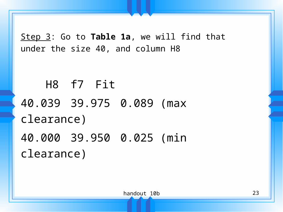
Step 3: Go to Table 1a, we will find that under the size
40, and column H8
H8 f7 Fit
40.039 39.975 0.089 (max clearance)
40.000 39.950 0.025 (min clearance)

handout 10b 24
Summary of the procedure
The following figures and table are used:
Figure 1: Get a preferred size as well as IT
grade
Figure 4: Get a preferred fit
Table 1a: Get tolerance

handout 10b 25

handout 10b 26
More Examples
Given: basic hole systemlocational transitional fitbasic diameter =57 mm
Figure 1 -> 60Figure 4 -> H7/k6Table 1: Hole Shaft
60.030 60.02160.000 60.002

handout 10b 27
Hole Shaft
60.030 60.021
60.000 60.002
-0.021 0.028
Max interference Max clearance
0.030 0.019
Tol
eran
ce
Tol
eran
ce

handout 10b 28
Representation on the drawing
60H760.03060.000( )
60.02160.002
60k660.02160.002( )