Embed Size (px)
Citation preview
© 2006 Texas Instruments Inc, Slide 1
Hands-on: Single TouchCapacitive Touch Sensing with MSP430
Steve UnderwoodMSP430 FAE AsiaTexas Instruments
© 2006 Texas Instruments Inc, Slide 2
Agenda• How can we sense a finger on a control?• How can we capacitively sense a finger?• The detailed issues in charge rate sensing• Experimenting with some code
LAB1-3: Basic touch pad detection – detecting the center pad of the “4”on the ATC boardLAB4: Achieving very low power consumptionLAB5: Extending a pad to a slider – detecting a single touch around the whole “4”
© 2006 Texas Instruments Inc, Slide 3
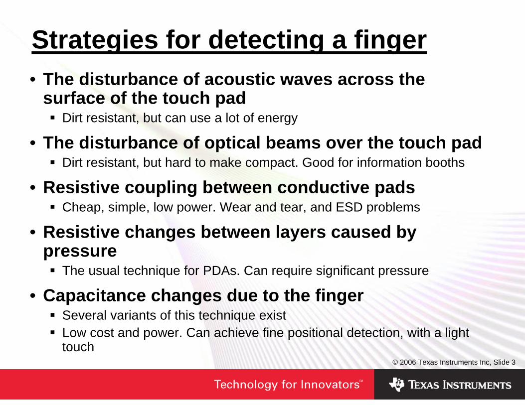
Strategies for detecting a finger• The disturbance of acoustic waves across the
surface of the touch padDirt resistant, but can use a lot of energy
• The disturbance of optical beams over the touch padDirt resistant, but hard to make compact. Good for information booths
• Resistive coupling between conductive padsCheap, simple, low power. Wear and tear, and ESD problems
• Resistive changes between layers caused by pressure
The usual technique for PDAs. Can require significant pressure
• Capacitance changes due to the fingerSeveral variants of this technique existLow cost and power. Can achieve fine positional detection, with a light touch
© 2006 Texas Instruments Inc, Slide 4
Agenda• How can we sense a finger on a control?• How can we capacitively sense a finger?• The detailed issues in charge rate sensing• Experimenting with some code
LAB1-3: Basic touch pad detection – detecting the center pad of the “4”on the ATC boardLAB4: Achieving very low power consumptionLAB5: Extending a pad to a slider – detecting a single touch around the whole “4”
© 2006 Texas Instruments Inc, Slide 5
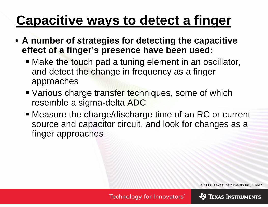
Capacitive ways to detect a finger• A number of strategies for detecting the capacitive
effect of a finger’s presence have been used:Make the touch pad a tuning element in an oscillator, and detect the change in frequency as a finger approachesVarious charge transfer techniques, some of which resemble a sigma-delta ADCMeasure the charge/discharge time of an RC or current source and capacitor circuit, and look for changes as a finger approaches
© 2006 Texas Instruments Inc, Slide 6
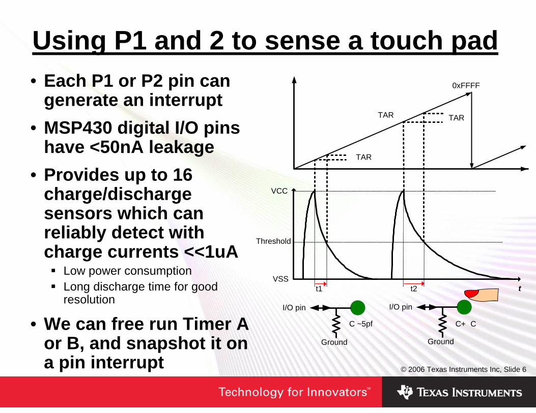
Using P1 and 2 to sense a touch pad• Each P1 or P2 pin can
generate an interrupt• MSP430 digital I/O pins
have <50nA leakage• Provides up to 16
charge/discharge sensors which can reliably detect with charge currents <<1uA
Low power consumptionLong discharge time for good resolution
• We can free run Timer A or B, and snapshot it on a pin interrupt
t
Threshold
VCC
VSSt1 t2
0xFFFF
TAR
� TAR
� TAR
C+� CC ~5pf
I/O pin
Ground
I/O pin
Ground
© 2006 Texas Instruments Inc, Slide 7
Agenda• How can we sense a finger on a control?• How can we capacitively sense a finger?• The detailed issues in charge rate sensing• Experimenting with some code
LAB1-3: Basic touch pad detection – detecting the center pad of the “4”on the ATC boardLAB4: Achieving very low power consumptionLAB5: Extending a pad to a slider – detecting a single touch around the whole “4”
© 2006 Texas Instruments Inc, Slide 8
50Hz/60Hz pickup• Touching a high impedance oscilloscope probe
produces a large mains waveform on the display• The same effect happens with a touch pad. Mains
pickup from touching or waving cables near the pad must be tolerated
• Heavy filtering of touch pad measurements would make the pad unresponsive
• If we measure the charge time, quickly followed by the discharge time, their average is only slightly affected by mains pickup
• Lightweight digital filtering can clean up the remainder of the mains effect. This gives a clean, responsive, measurement of the effects of a finger
© 2006 Texas Instruments Inc, Slide 9
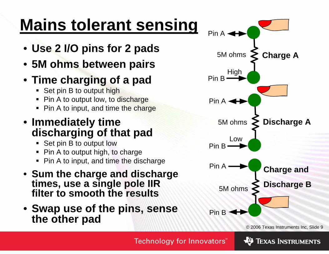
Mains tolerant sensing• Use 2 I/O pins for 2 pads• 5M ohms between pairs• Time charging of a pad
Set pin B to output highPin A to output low, to dischargePin A to input, and time the charge
• Immediately time discharging of that pad
Set pin B to output lowPin A to output high, to chargePin A to input, and time the discharge
• Sum the charge and discharge times, use a single pole IIR filter to smooth the results
• Swap use of the pins, sense the other pad
Pin A
Pin B
5M ohms
Pin A
Pin B
5M ohms
Pin A
Pin B
5M ohms
High
Low
Charge A
Discharge A
Charge and
Discharge B
© 2006 Texas Instruments Inc, Slide 10
Other sources of interference• Tolerance of other internal and external sources of
interference may be important• Cellular phones may be a problem• Interference from fast logic in the product itself may
be an issueA clean power supply for the MSP430 is importantA stable supply for the MSP430 is importantGood screening and ground plane layout on the sensing PCB is important
© 2006 Texas Instruments Inc, Slide 11
Labs ahead – let’s get prepared• The ATC board contains an MSP430FG4619, which
has an LCD and an isolated RS232C port. We will use this MCU to receive key information by I2C, display it and also pass it to a PC, by RS232C – you will need a working serial port on your PC for this
• The board contains an MSP430F2013, which connects to the 16 pads which form the large “4”. It also connects by I2C to the MSP430FG4619
Eight I/O pins are used for the pads – 2 pads to each I/O pinFour 5.1Mohm resistors are connected between pairs of I/O pins
• Header H1 must have only jumpers 1-2 and 3-4 fitted• Jumper JP2 must be removed, so LED3 does not
affect touch pad sensing
© 2006 Texas Instruments Inc, Slide 12
Agenda• How can we sense a finger on a control?• How can we capacitively sense a finger?• The detailed issues in charge rate sensing• Experimenting with some code
LAB1-3: Basic touch pad detection – detecting the center pad of the “4”on the ATC boardLAB4: Achieving very low power consumptionLAB5: Extending a pad to a slider – detecting a single touch around the whole “4”
© 2006 Texas Instruments Inc, Slide 13
A basic touch button• We will now look at some core sensing code,
implementing the basic technique we have looked at• In this initial exercise we will only sense the big
square pad at the centre of the “4”• The provided code for the MSP430FG4619 can be
compiled, loaded into the device and used without change
• The provided code for the MSP430F2013 will be used as the basis for some experiments
• After this we will extend the sensing technique to more complex requirements
© 2006 Texas Instruments Inc, Slide 14
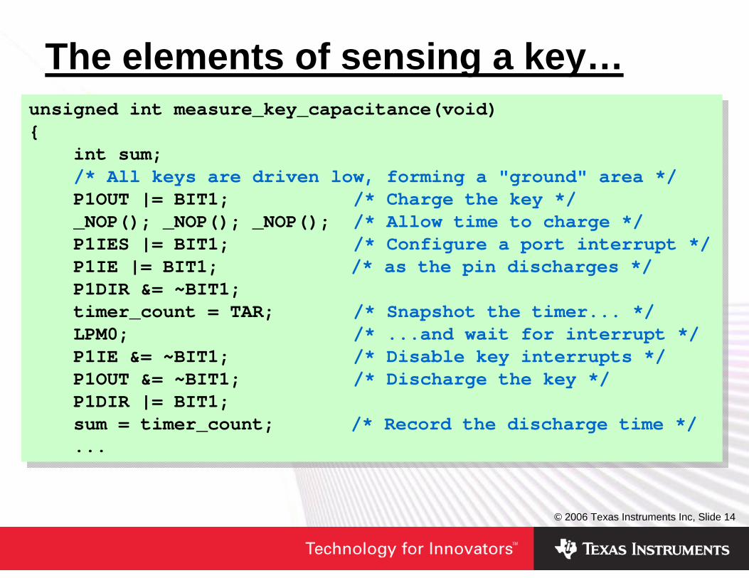
The elements of sensing a key…unsigned int measure_key_capacitance(void){
int sum;/* All keys are driven low, forming a "ground" area */P1OUT |= BIT1; /* Charge the key */_NOP(); _NOP(); _NOP(); /* Allow time to charge */P1IES |= BIT1; /* Configure a port interrupt */P1IE |= BIT1; /* as the pin discharges */P1DIR &= ~BIT1;timer_count = TAR; /* Snapshot the timer... */LPM0; /* ...and wait for interrupt */P1IE &= ~BIT1; /* Disable key interrupts */P1OUT &= ~BIT1; /* Discharge the key */P1DIR |= BIT1;sum = timer_count; /* Record the discharge time */...
unsigned int measure_key_capacitance(void){
int sum;/* All keys are driven low, forming a "ground" area */P1OUT |= BIT1; /* Charge the key */_NOP(); _NOP(); _NOP(); /* Allow time to charge */P1IES |= BIT1; /* Configure a port interrupt */P1IE |= BIT1; /* as the pin discharges */P1DIR &= ~BIT1;timer_count = TAR; /* Snapshot the timer... */LPM0; /* ...and wait for interrupt */P1IE &= ~BIT1; /* Disable key interrupts */P1OUT &= ~BIT1; /* Discharge the key */P1DIR |= BIT1;sum = timer_count; /* Record the discharge time */...
© 2006 Texas Instruments Inc, Slide 15
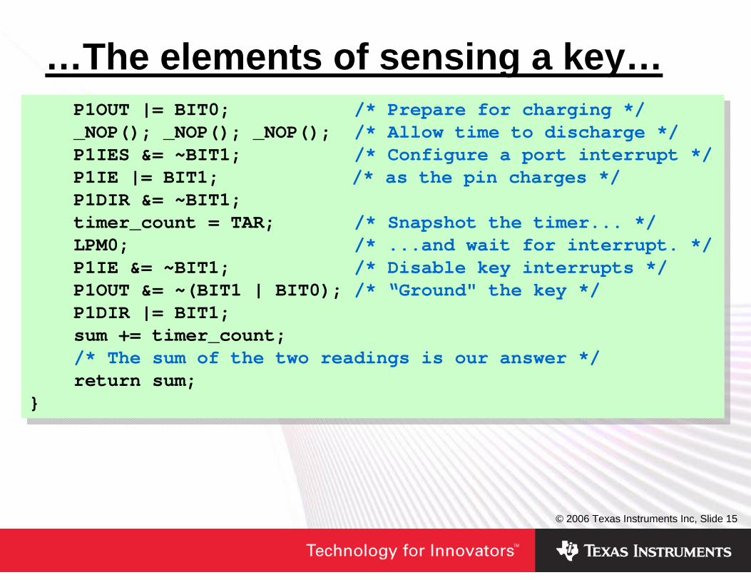
…The elements of sensing a key…P1OUT |= BIT0; /* Prepare for charging */_NOP(); _NOP(); _NOP(); /* Allow time to discharge */P1IES &= ~BIT1; /* Configure a port interrupt */P1IE |= BIT1; /* as the pin charges */P1DIR &= ~BIT1;timer_count = TAR; /* Snapshot the timer... */LPM0; /* ...and wait for interrupt. */P1IE &= ~BIT1; /* Disable key interrupts */P1OUT &= ~(BIT1 | BIT0); /* “Ground" the key */P1DIR |= BIT1;sum += timer_count;/* The sum of the two readings is our answer */return sum;
}
P1OUT |= BIT0; /* Prepare for charging */_NOP(); _NOP(); _NOP(); /* Allow time to discharge */P1IES &= ~BIT1; /* Configure a port interrupt */P1IE |= BIT1; /* as the pin charges */P1DIR &= ~BIT1;timer_count = TAR; /* Snapshot the timer... */LPM0; /* ...and wait for interrupt. */P1IE &= ~BIT1; /* Disable key interrupts */P1OUT &= ~(BIT1 | BIT0); /* “Ground" the key */P1DIR |= BIT1;sum += timer_count;/* The sum of the two readings is our answer */return sum;
}
© 2006 Texas Instruments Inc, Slide 16
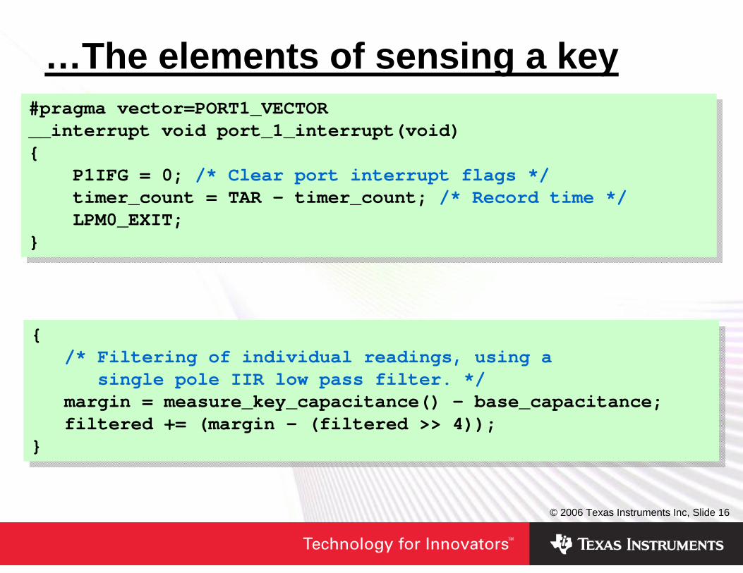
…The elements of sensing a key#pragma vector=PORT1_VECTOR__interrupt void port_1_interrupt(void){
P1IFG = 0; /* Clear port interrupt flags */timer_count = TAR - timer_count; /* Record time */LPM0_EXIT;
}
#pragma vector=PORT1_VECTOR__interrupt void port_1_interrupt(void){
P1IFG = 0; /* Clear port interrupt flags */timer_count = TAR - timer_count; /* Record time */LPM0_EXIT;
}
{/* Filtering of individual readings, using a
single pole IIR low pass filter. */margin = measure_key_capacitance() - base_capacitance;filtered += (margin - (filtered >> 4));
}
{/* Filtering of individual readings, using a
single pole IIR low pass filter. */margin = measure_key_capacitance() - base_capacitance;filtered += (margin - (filtered >> 4));
}
© 2006 Texas Instruments Inc, Slide 17
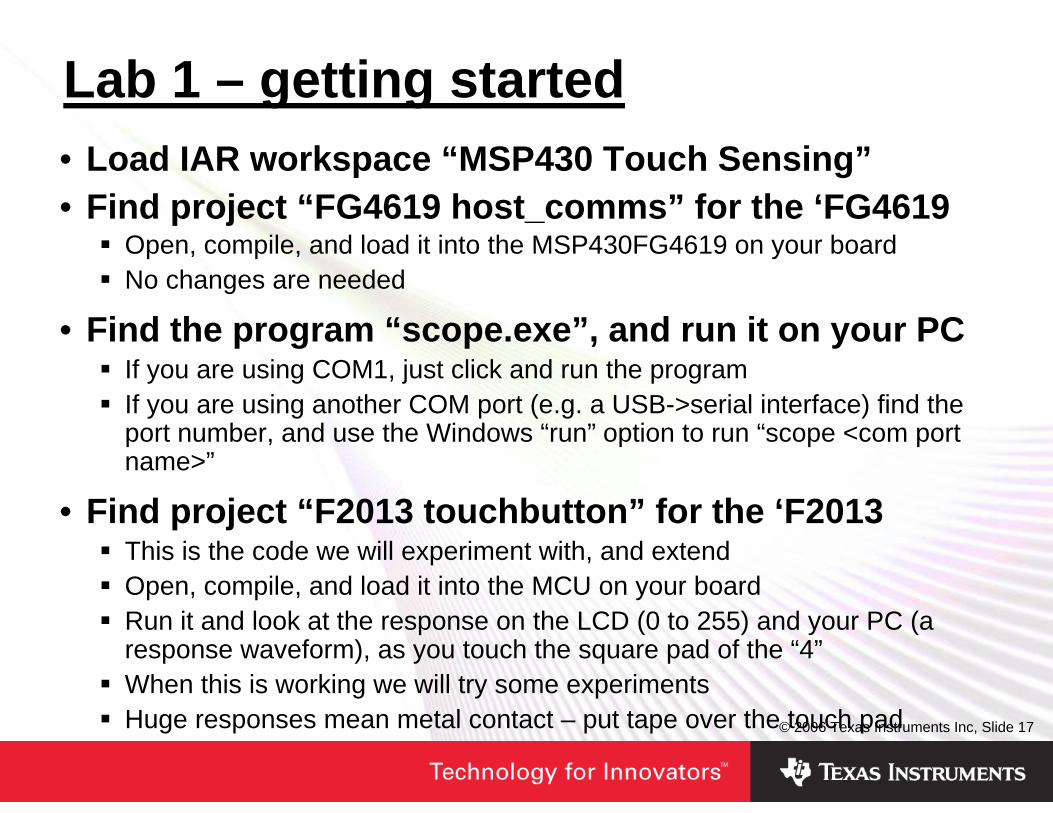
Lab 1 – getting started• Load IAR workspace “MSP430 Touch Sensing”• Find project “FG4619 host_comms” for the ‘FG4619
Open, compile, and load it into the MSP430FG4619 on your boardNo changes are needed
• Find the program “scope.exe”, and run it on your PCIf you are using COM1, just click and run the programIf you are using another COM port (e.g. a USB->serial interface) find the port number, and use the Windows “run” option to run “scope <com port name>”
• Find project “F2013 touchbutton” for the ‘F2013This is the code we will experiment with, and extendOpen, compile, and load it into the MCU on your boardRun it and look at the response on the LCD (0 to 255) and your PC (a response waveform), as you touch the square pad of the “4”When this is working we will try some experimentsHuge responses mean metal contact – put tape over the touch pad
© 2006 Texas Instruments Inc, Slide 18
The effect of insulators• The ATC board only separates your finger from the
capacitor plates by a thin film of solder resist• A real product will require an insulating layer –
typically the plastic case• Insulator material matters
It is the dielectric in a capacitorUse of non-hygroscopic glues is especially importantStable attachment, with no air gaps is important
• Insulator thickness has a big impact on the response from a pad
• Insulator thickness varies considerably0.5mm of textured plastic on the touchpad of your notebook10mm thick glass panel on a kitchen appliance1 to 2mm of plastic is more common
© 2006 Texas Instruments Inc, Slide 19
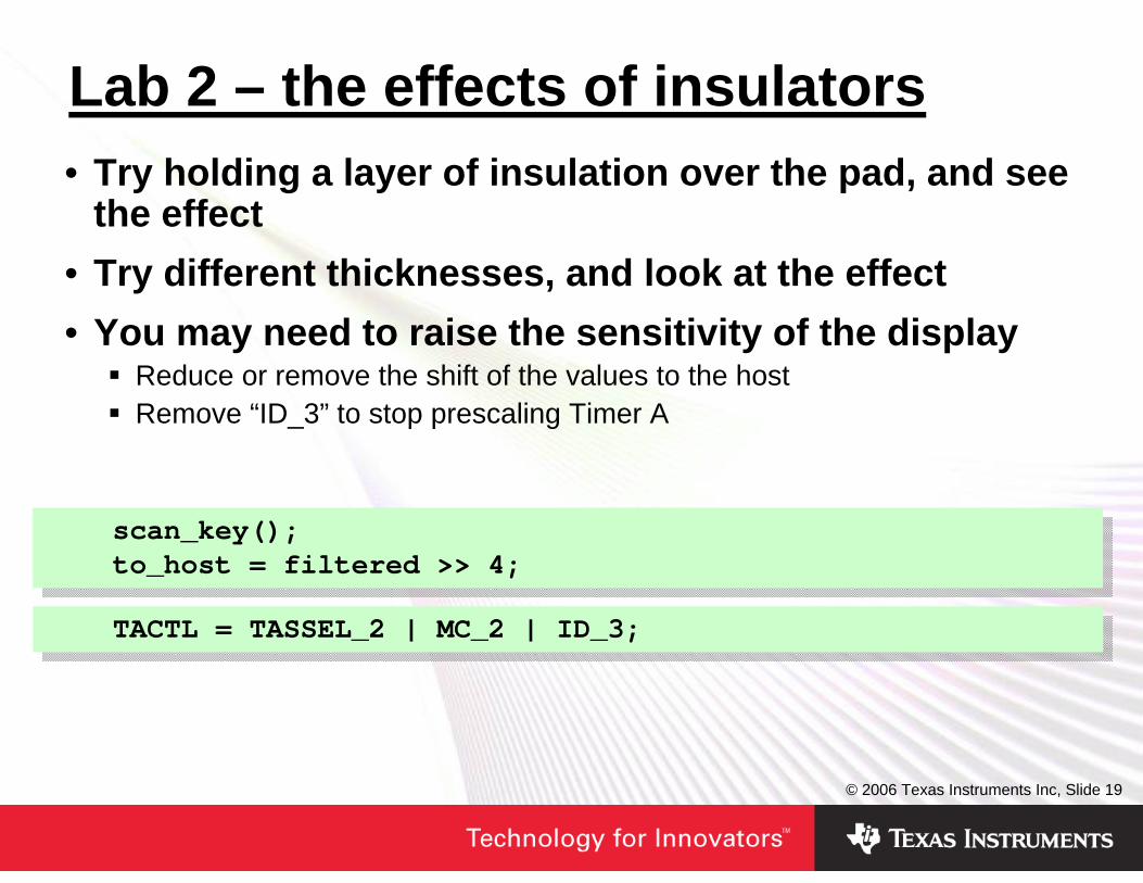
Lab 2 – the effects of insulators• Try holding a layer of insulation over the pad, and see
the effect• Try different thicknesses, and look at the effect• You may need to raise the sensitivity of the display
Reduce or remove the shift of the values to the hostRemove “ID_3” to stop prescaling Timer A
scan_key();to_host = filtered >> 4;
scan_key();to_host = filtered >> 4;
TACTL = TASSEL_2 | MC_2 | ID_3;TACTL = TASSEL_2 | MC_2 | ID_3;
© 2006 Texas Instruments Inc, Slide 20
Adapting to environmental change• We must calibrate each pad at startup
Components varyMechanical assembly (glue, etc.) varies
• We need to dynamically adapt that calibrationCapacitance and the input threshold vary with temperatureSupply voltage and other parameters may drift
• We need to avoid adapting to the wrong thingHands waving near the touch pad should not cause the threshold to rise undulyObviously we should not adapt when a finger is detectedWe should freeze adaptation of all keys, when any one is detectingAdapt slowly, as real changes occur slowlyAdapting downwards faster than we adapt up helps tolerate waving hands
• A fixed threshold above the base capacitance works OK for touch switches
© 2006 Texas Instruments Inc, Slide 21
Lab 3 – a single touch switch• The code already measures and sets an initial “base”
capacitance, at startup• 1. Try to make it implement a fixed threshold for key
detection – i.e. a switchYou can simply implement a fixed threshold that suits the tolerances of your own board, by running and measuring the readingsA value between 0 and 255 is being sent to the MSP430FG4619, so try to change this to 0 for off and 255 for on
• 2. Try to adapt the base capacitance dynamically to respond to changes in temperature, etc
What would be a good adaptation scheme?Should you adapt faster when the signal is farther from its base level?How much faster should you adapt downwards than you adapt upwards?
© 2006 Texas Instruments Inc, Slide 22
Disturbances from other I/O• We have seen that practical insulation cover can
make the response from a finger very small• The thickness of the PCB also affects the response
Thin PCBs in hand-held products give a smaller responseThe increasing popularity of very thin flexible PCBs for small consumer products made things even harder
• Noise from other I/O on the MCU can disturb results• The most stable results are achieved if I/O only
occurs between scans of the touch pad

© 2006 Texas Instruments Inc, Slide 23
Agenda• How can we sense a finger on a control?• How can we capacitively sense a finger?• The detailed issues in charge rate sensing• Experimenting with some code
LAB1-3: Basic touch pad detection – detecting the center pad of the “4”on the ATC boardLAB4: Achieving very low power consumptionLAB5: Extending a pad to a slider – detecting a single touch around the whole “4”
© 2006 Texas Instruments Inc, Slide 24
Minimizing power consumption• Many touch pad applications are in portable
appliances, so power consumption is important• We charge and discharge in LPM0 – tens of μA• We can rest between scans in LPM3 – <1 μA• Average consumption can be very low• Rapidly scanning sliders, for good response takes
<<1mA overallWe can keep the MCU in the LPM0 state for much of the time
• Scanning a single pad at a low rate we can achieve 5uA consumption
We can use a low scan rate waiting for the “on” switch to be pressedWe don’t need a strong response, as we are not interpolating
© 2006 Texas Instruments Inc, Slide 25
Lab 4 – low power operation• Minimize power consumption as we wait for a single
key to be pressedLike a real product, saving power, waiting for the “on” button to be pressed
• Try to adapt the code from the last exercise to minimize its power consumption
The code currently idles in a loop between key scansTry to make it sleep in LPM3 during these idle periodsInterrupts can be generated from the watchdog, for simplicityThere is no 32kHz crystal for the MSP430F2013 on this board, but there is the VLO. It runs at ~12kHz, and is operating as the ACLK source in this code
© 2006 Texas Instruments Inc, Slide 26
Agenda• How can we sense a finger on a control?• How can we capacitively sense a finger?• The detailed issues in charge rate sensing• Experimenting with some code
LAB1-3: Basic touch pad detection – detecting the center pad of the “4”on the ATC boardLAB4: Achieving very low power consumptionLAB5: Extending a pad to a slider – detecting a single touch around the whole “4”
© 2006 Texas Instruments Inc, Slide 27
Extending a button to a slider• People tend to be most interested in touch pads for
sliders, dials, and other complex configurations• The benefits of tactile feedback reduce the
acceptability of individual touch buttons for some applications
• Fine resolution sliders can be made with a row of just a few individual pads, using interpolation
Thick insulation would make this harder
• Usable pad size is related to the size of the fingerA finger needs to excite multiple padsA compromise size can work well for children and large adultsThe “4” has oversized pads at the extreme top and left, which compromise its performance – this is a demo, not an end product
© 2006 Texas Instruments Inc, Slide 28
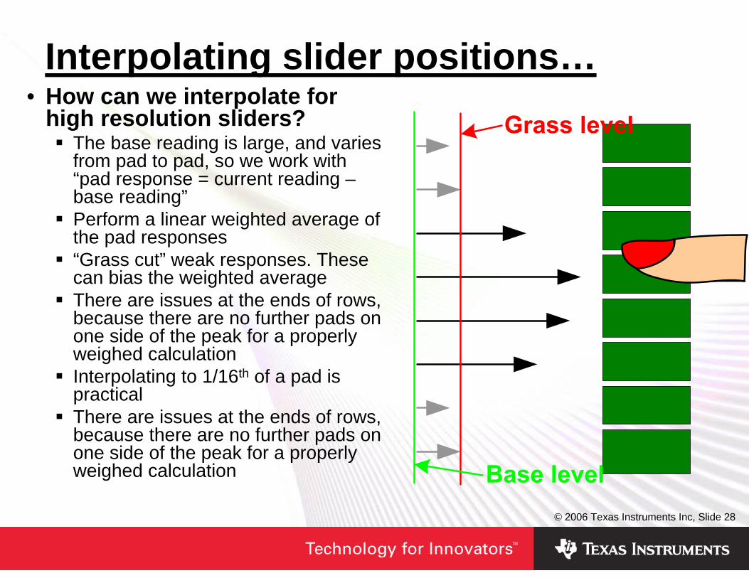
Interpolating slider positions…• How can we interpolate for
high resolution sliders?The base reading is large, and varies from pad to pad, so we work with “pad response = current reading –base reading”Perform a linear weighted average of the pad responses“Grass cut” weak responses. These can bias the weighted averageThere are issues at the ends of rows, because there are no further pads on one side of the peak for a properly weighed calculationInterpolating to 1/16th of a pad is practicalThere are issues at the ends of rows, because there are no further pads on one side of the peak for a properly weighed calculation
© 2006 Texas Instruments Inc, Slide 29
…Interpolating slider positions• What will affect the stability of the positional
estimate?Noise will cause some jitteriness in the positional estimateThe finger still moves a little while “stationary”As a finger lifts, we need to avoid generating false steps
• How can we smooth out these effects?Most applications are looking for movement along a slider, rather than absolute positionUse hysteresis in accepting apparent changes of finger directionUp to half a pad of hysteresis is needed for good results as a finger liftsSoft flesh flexes as we change direction, so there is a natural dead zone, regardless of hysteresis we introduce. The final feeling is quite natural
© 2006 Texas Instruments Inc, Slide 30
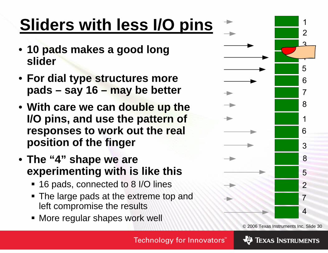
Sliders with less I/O pins• 10 pads makes a good long
slider• For dial type structures more
pads – say 16 – may be better• With care we can double up the
I/O pins, and use the pattern of responses to work out the real position of the finger
• The “4” shape we are experimenting with is like this
16 pads, connected to 8 I/O linesThe large pads at the extreme top and left compromise the resultsMore regular shapes work well
© 2006 Texas Instruments Inc, Slide 31
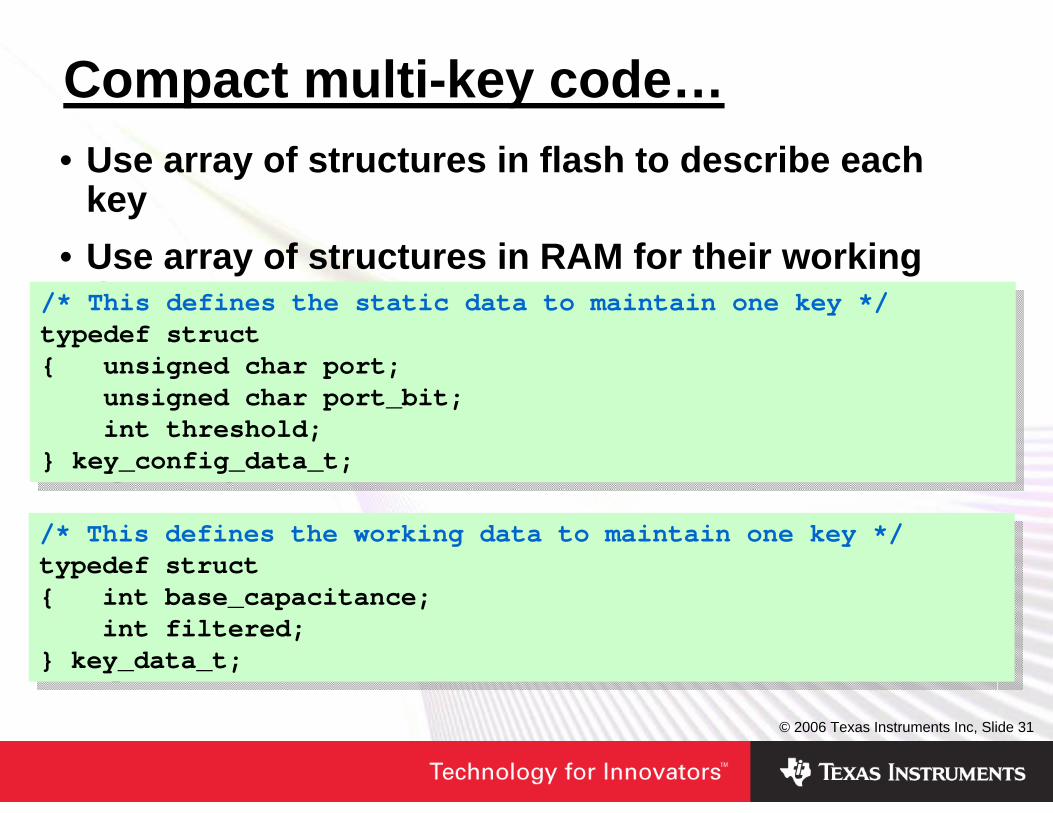
Compact multi-key code…• Use array of structures in flash to describe each
key• Use array of structures in RAM for their working
data/* This defines the static data to maintain one key */typedef struct{ unsigned char port;
unsigned char port_bit;int threshold;
} key_config_data_t;
/* This defines the static data to maintain one key */typedef struct{ unsigned char port;
unsigned char port_bit;int threshold;
} key_config_data_t;
/* This defines the working data to maintain one key */typedef struct{ int base_capacitance;
int filtered;} key_data_t;
/* This defines the working data to maintain one key */typedef struct{ int base_capacitance;
int filtered;} key_data_t;
© 2006 Texas Instruments Inc, Slide 32
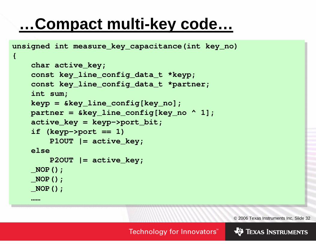
…Compact multi-key code…unsigned int measure_key_capacitance(int key_no){
char active_key;const key_line_config_data_t *keyp;const key_line_config_data_t *partner;int sum;keyp = &key_line_config[key_no];partner = &key_line_config[key_no ^ 1];active_key = keyp->port_bit;if (keyp->port == 1)
P1OUT |= active_key;else
P2OUT |= active_key;_NOP();_NOP();_NOP();……
unsigned int measure_key_capacitance(int key_no){
char active_key;const key_line_config_data_t *keyp;const key_line_config_data_t *partner;int sum;keyp = &key_line_config[key_no];partner = &key_line_config[key_no ^ 1];active_key = keyp->port_bit;if (keyp->port == 1)
P1OUT |= active_key;else
P2OUT |= active_key;_NOP();_NOP();_NOP();……
© 2006 Texas Instruments Inc, Slide 33
…Compact multi-key code…
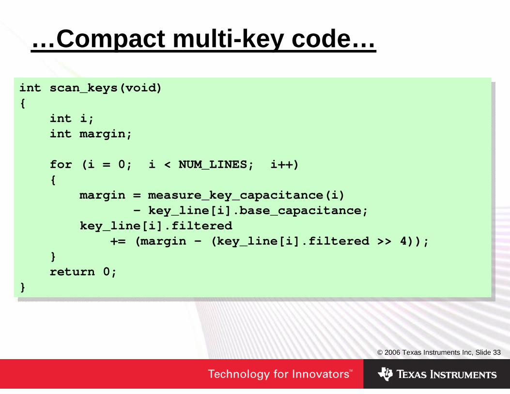
int scan_keys(void){
int i;int margin;
for (i = 0; i < NUM_LINES; i++){
margin = measure_key_capacitance(i)- key_line[i].base_capacitance;
key_line[i].filtered+= (margin - (key_line[i].filtered >> 4));
}return 0;
}
int scan_keys(void){
int i;int margin;
for (i = 0; i < NUM_LINES; i++){
margin = measure_key_capacitance(i)- key_line[i].base_capacitance;
key_line[i].filtered+= (margin - (key_line[i].filtered >> 4));
}return 0;
}
© 2006 Texas Instruments Inc, Slide 34
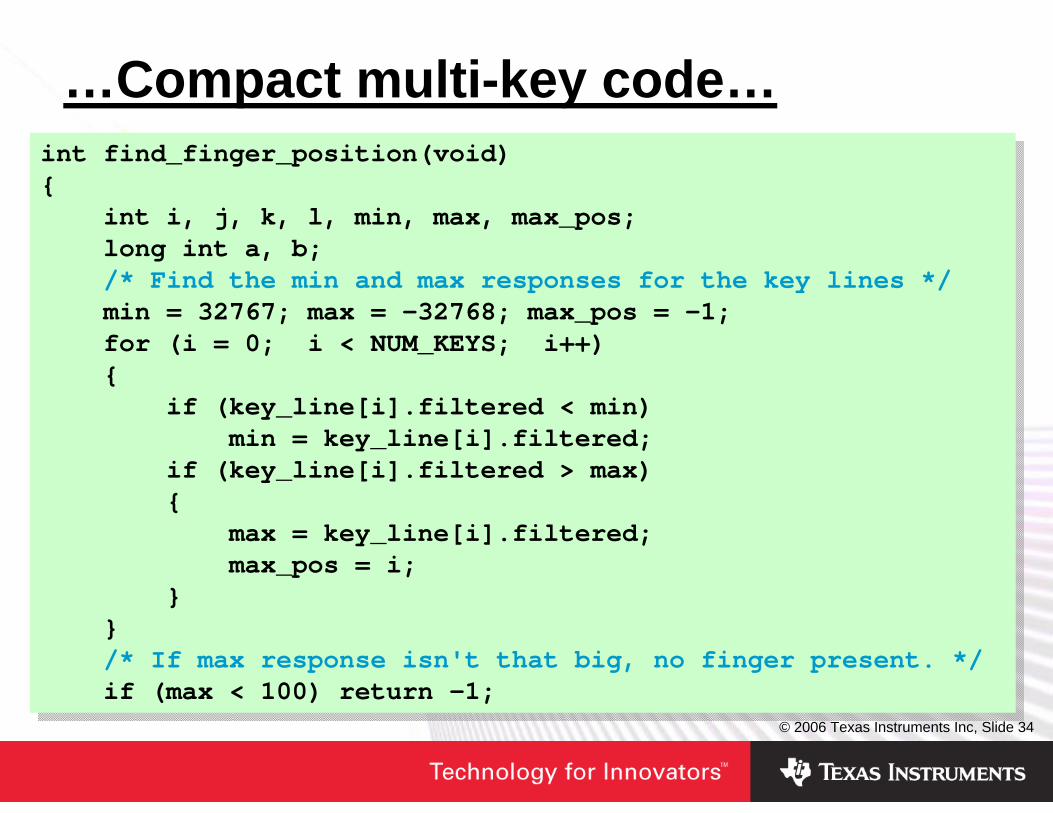
…Compact multi-key code…int find_finger_position(void){
int i, j, k, l, min, max, max_pos;long int a, b;/* Find the min and max responses for the key lines */min = 32767; max = -32768; max_pos = -1;for (i = 0; i < NUM_KEYS; i++){
if (key_line[i].filtered < min)min = key_line[i].filtered;
if (key_line[i].filtered > max){
max = key_line[i].filtered;max_pos = i;
}}/* If max response isn't that big, no finger present. */if (max < 100) return -1;
int find_finger_position(void){
int i, j, k, l, min, max, max_pos;long int a, b;/* Find the min and max responses for the key lines */min = 32767; max = -32768; max_pos = -1;for (i = 0; i < NUM_KEYS; i++){
if (key_line[i].filtered < min)min = key_line[i].filtered;
if (key_line[i].filtered > max){
max = key_line[i].filtered;max_pos = i;
}}/* If max response isn't that big, no finger present. */if (max < 100) return -1;
© 2006 Texas Instruments Inc, Slide 35
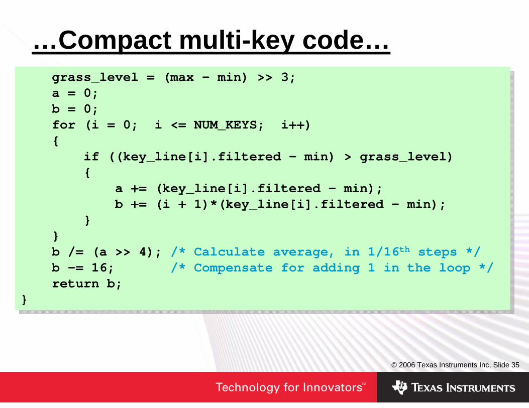
…Compact multi-key code…grass_level = (max - min) >> 3;a = 0;b = 0;for (i = 0; i <= NUM_KEYS; i++){
if ((key_line[i].filtered - min) > grass_level){
a += (key_line[i].filtered - min);b += (i + 1)*(key_line[i].filtered - min);
}}b /= (a >> 4); /* Calculate average, in 1/16th steps */b -= 16; /* Compensate for adding 1 in the loop */return b;
}
grass_level = (max - min) >> 3;a = 0;b = 0;for (i = 0; i <= NUM_KEYS; i++){
if ((key_line[i].filtered - min) > grass_level){
a += (key_line[i].filtered - min);b += (i + 1)*(key_line[i].filtered - min);
}}b /= (a >> 4); /* Calculate average, in 1/16th steps */b -= 16; /* Compensate for adding 1 in the loop */return b;
}
© 2006 Texas Instruments Inc, Slide 36
Lab 5 – a touch slider• We will sweep through all the pads of the “4”, and
estimate the finger position• Find the program “touch4.exe” and run it on your PC
Provides a visual monitor of the position of a finger on the “4”If your comms port is not COM1, use the Windows “run” option to run “touch4 <com port name>”
• Find project “F2013 touchpad” for the ‘F2013Editing the previous 2013 to work with many pads would take too longThis project has the bulk of the editing done for youIt uses similar code to that in the previous slides, further extended to deal with the 2 keys per I/O configurationIt implements the weighted averaging scheme
© 2006 Texas Instruments Inc, Slide 37
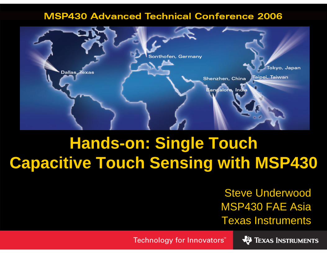
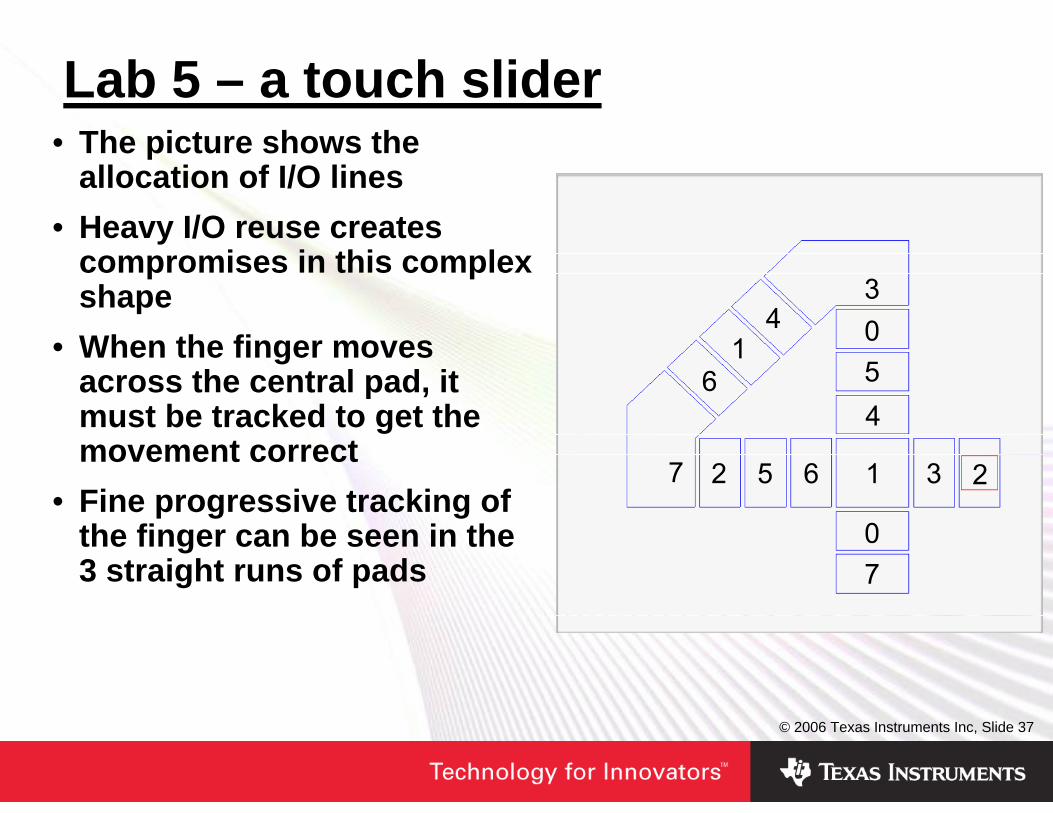
Lab 5 – a touch slider• The picture shows the
allocation of I/O lines• Heavy I/O reuse creates
compromises in this complex shape
• When the finger moves across the central pad, it must be tracked to get the movement correct
• Fine progressive tracking of the finger can be seen in the 3 straight runs of pads
© 2006 Texas Instruments Inc, Slide 38
Summary• For requirements up to 16 sense lines, the
charge/discharge approach to capacitive sensing works very well with the MSP430
• Very low power consumption is possible• Simple switches can be implemented with thick
insulation• Interpolation allows fine resolution sliders to be
implemented through the typical plastic shell of a handheld device
IMPORTANT NOTICE
Texas Instruments Incorporated and its subsidiaries (TI) reserve the right to make corrections, modifications, enhancements,improvements, and other changes to its products and services at any time and to discontinue any product or service without notice.Customers should obtain the latest relevant information before placing orders and should verify that such information is current andcomplete. All products are sold subject to TI’s terms and conditions of sale supplied at the time of order acknowledgment.
TI warrants performance of its hardware products to the specifications applicable at the time of sale in accordance with TI’sstandard warranty. Testing and other quality control techniques are used to the extent TI deems necessary to support thiswarranty. Except where mandated by government requirements, testing of all parameters of each product is not necessarilyperformed.
TI assumes no liability for applications assistance or customer product design. Customers are responsible for their products andapplications using TI components. To minimize the risks associated with customer products and applications, customers shouldprovide adequate design and operating safeguards.
TI does not warrant or represent that any license, either express or implied, is granted under any TI patent right, copyright, maskwork right, or other TI intellectual property right relating to any combination, machine, or process in which TI products or servicesare used. Information published by TI regarding third-party products or services does not constitute a license from TI to use suchproducts or services or a warranty or endorsement thereof. Use of such information may require a license from a third party underthe patents or other intellectual property of the third party, or a license from TI under the patents or other intellectual property of TI.
Reproduction of TI information in TI data books or data sheets is permissible only if reproduction is without alteration and isaccompanied by all associated warranties, conditions, limitations, and notices. Reproduction of this information with alteration is anunfair and deceptive business practice. TI is not responsible or liable for such altered documentation. Information of third partiesmay be subject to additional restrictions.
Resale of TI products or services with statements different from or beyond the parameters stated by TI for that product or servicevoids all express and any implied warranties for the associated TI product or service and is an unfair and deceptive businesspractice. TI is not responsible or liable for any such statements.
TI products are not authorized for use in safety-critical applications (such as life support) where a failure of the TI product wouldreasonably be expected to cause severe personal injury or death, unless officers of the parties have executed an agreementspecifically governing such use. Buyers represent that they have all necessary expertise in the safety and regulatory ramificationsof their applications, and acknowledge and agree that they are solely responsible for all legal, regulatory and safety-relatedrequirements concerning their products and any use of TI products in such safety-critical applications, notwithstanding anyapplications-related information or support that may be provided by TI. Further, Buyers must fully indemnify TI and itsrepresentatives against any damages arising out of the use of TI products in such safety-critical applications.
TI products are neither designed nor intended for use in military/aerospace applications or environments unless the TI products arespecifically designated by TI as military-grade or "enhanced plastic." Only products designated by TI as military-grade meet militaryspecifications. Buyers acknowledge and agree that any such use of TI products which TI has not designated as military-grade issolely at the Buyer's risk, and that they are solely responsible for compliance with all legal and regulatory requirements inconnection with such use.
TI products are neither designed nor intended for use in automotive applications or environments unless the specific TI productsare designated by TI as compliant with ISO/TS 16949 requirements. Buyers acknowledge and agree that, if they use anynon-designated products in automotive applications, TI will not be responsible for any failure to meet such requirements.
Following are URLs where you can obtain information on other Texas Instruments products and application solutions:
Products Applications
Amplifiers amplifier.ti.com Audio www.ti.com/audio
Data Converters dataconverter.ti.com Automotive www.ti.com/automotive
DSP dsp.ti.com Broadband www.ti.com/broadband
Interface interface.ti.com Digital Control www.ti.com/digitalcontrol
Logic logic.ti.com Military www.ti.com/military
Power Mgmt power.ti.com Optical Networking www.ti.com/opticalnetwork
Microcontrollers microcontroller.ti.com Security www.ti.com/security
RFID www.ti-rfid.com Telephony www.ti.com/telephony
Low Power www.ti.com/lpw Video & Imaging www.ti.com/videoWireless
Wireless www.ti.com/wireless
Mailing Address: Texas Instruments, Post Office Box 655303, Dallas, Texas 75265Copyright © 2007, Texas Instruments Incorporated