Embed Size (px)
Citation preview

Hands-on: Factory Design Suite 2014 1 | 35
Hands-on: Factory Design Suite 2014
90 minutes Hands-on For Beginners
Peter De Strijker - Technical Specialist, Autodesk Benelux
Hands-on: Factory Design Suite 2014 2 | 35
User Assets Library It’s important to be able to populate the library with user specific assets. Let’s create one!
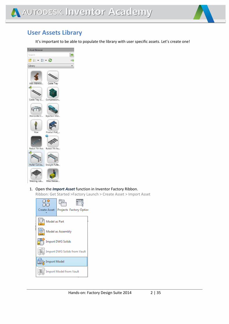
1. Open the Import Asset function in Inventor Factory Ribbon. Ribbon: Get Started >Factory Launch > Create Asset > Import Asset
Hands-on: Factory Design Suite 2014 3 | 35
Select <FDS-ROOT>\ FDS HandsOn\Production Area\AssetCreation\ Robot Controller.ipt file and click Open.
The model is loaded into the Asset Builder.
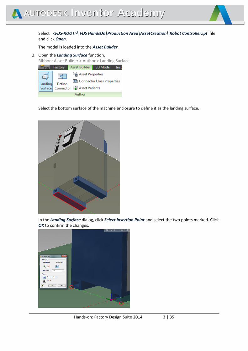
2. Open the Landing Surface function. Ribbon: Asset Builder > Author > Landing Surface
Select the bottom surface of the machine enclosure to define it as the landing surface.
In the Landing Surface dialog, click Select Insertion Point and select the two points marked. Click OK to confirm the changes.
Hands-on: Factory Design Suite 2014 4 | 35
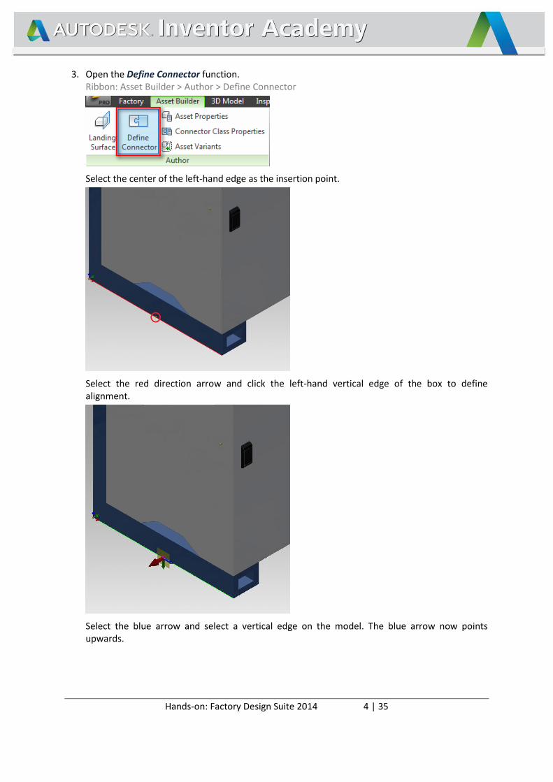
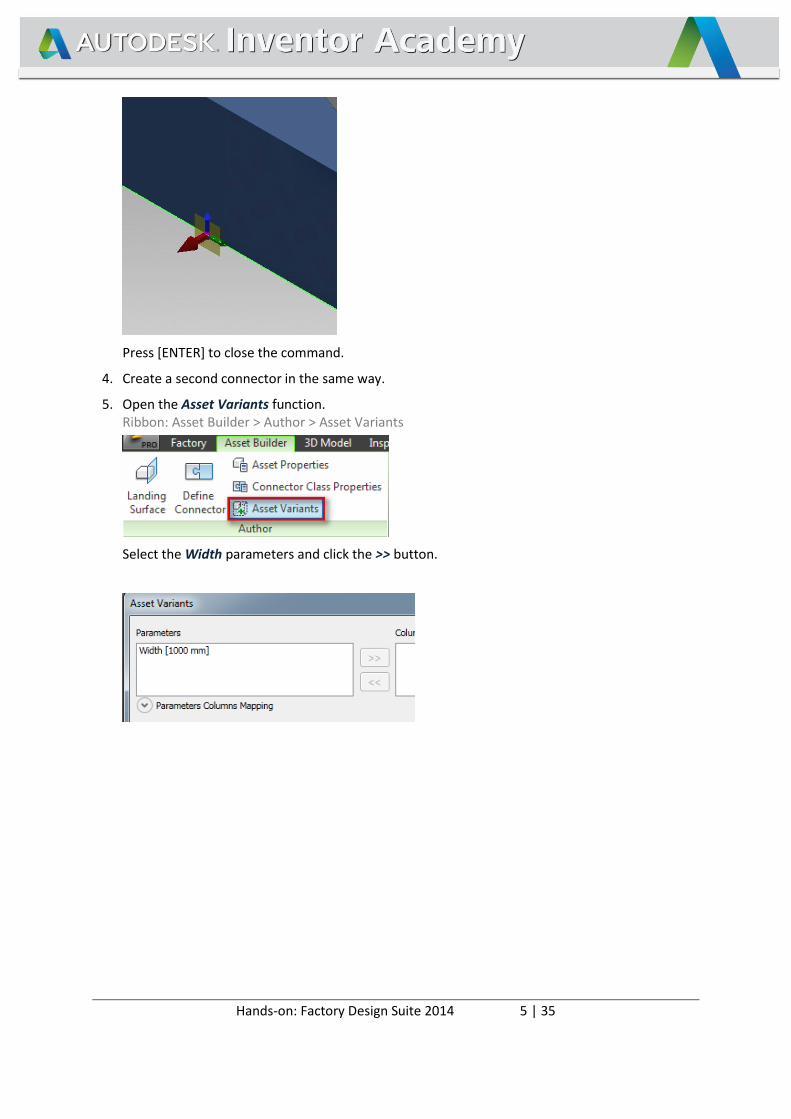
3. Open the Define Connector function. Ribbon: Asset Builder > Author > Define Connector
Select the center of the left-hand edge as the insertion point.
Select the red direction arrow and click the left-hand vertical edge of the box to define alignment.
Select the blue arrow and select a vertical edge on the model. The blue arrow now points upwards.
Hands-on: Factory Design Suite 2014 5 | 35
Press [ENTER] to close the command.
4. Create a second connector in the same way.
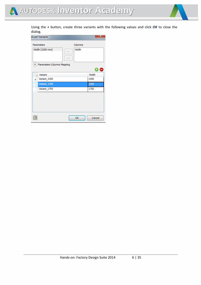
5. Open the Asset Variants function. Ribbon: Asset Builder > Author > Asset Variants
Select the Width parameters and click the >> button.
Hands-on: Factory Design Suite 2014 6 | 35
Using the + button, create three variants with the following values and click OK to close the dialog.
Hands-on: Factory Design Suite 2014 7 | 35
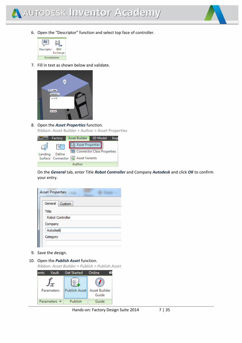
6. Open the “Descriptor” function and select top face of controller.
7. Fill in text as shown below and validate.
8. Open the Asset Properties function. Ribbon: Asset Builder > Author > Asset Properties
On the General tab, enter Title Robot Controller and Company Autodesk and click OK to confirm your entry.
9. Save the design.
10. Open the Publish Asset function. Ribbon: Asset Builder > Publish > Publish Asset
Hands-on: Factory Design Suite 2014 8 | 35
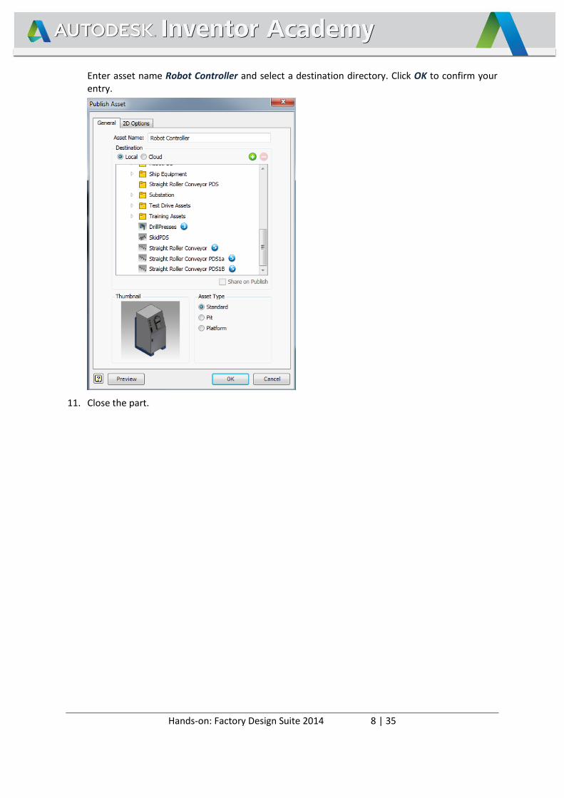
Enter asset name Robot Controller and select a destination directory. Click OK to confirm your entry.
11. Close the part.
Hands-on: Factory Design Suite 2014 9 | 35
Create a New Sub Layout Area
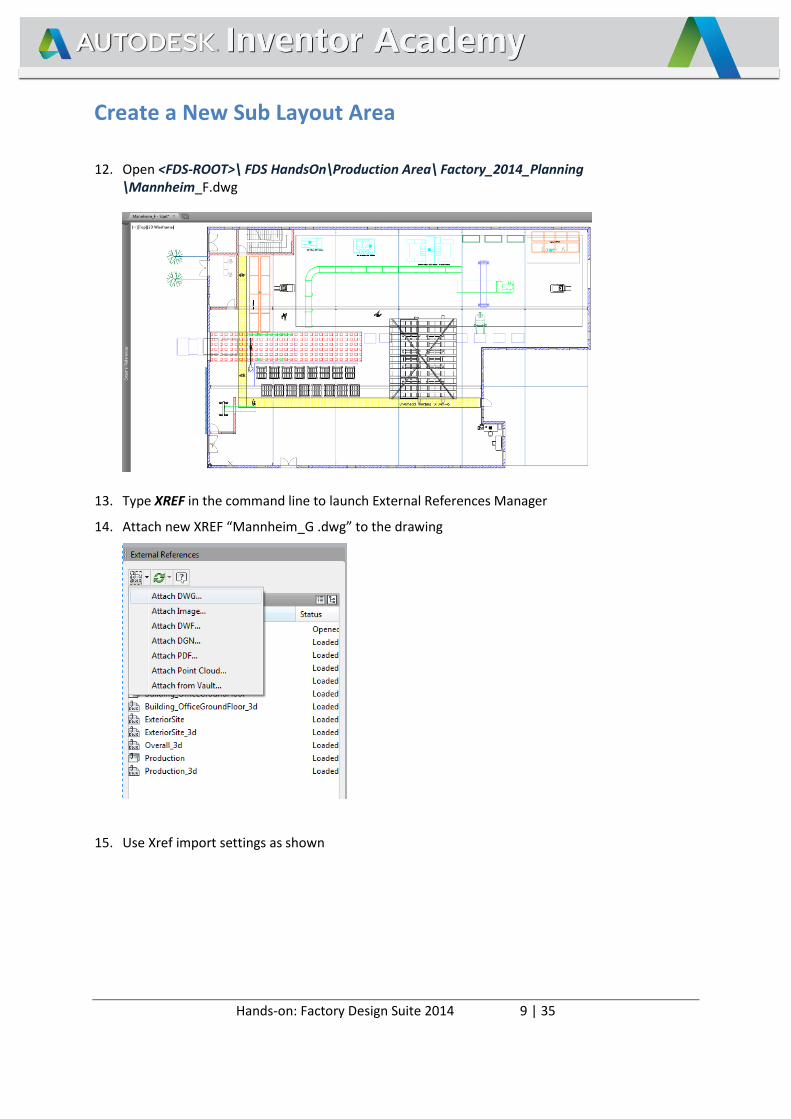
12. Open <FDS-ROOT>\ FDS HandsOn\Production Area\ Factory_2014_Planning \Mannheim_F.dwg
13. Type XREF in the command line to launch External References Manager
14. Attach new XREF “Mannheim_G .dwg” to the drawing
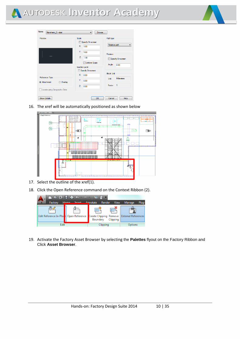
15. Use Xref import settings as shown
Hands-on: Factory Design Suite 2014 10 | 35
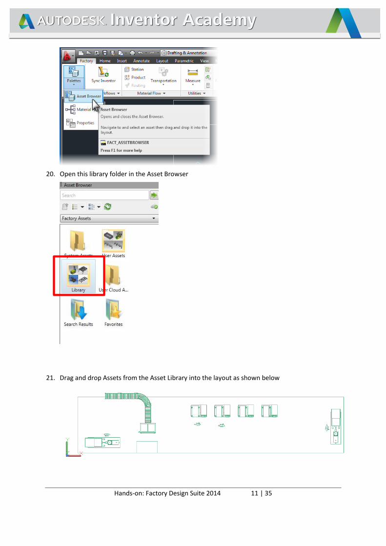
16. The xref will be automatically positioned as shown below
17. Select the outline of the xref(1).
18. Click the Open Reference command on the Context Ribbon (2).
19. Activate the Factory Asset Browser by selecting the Palettes flyout on the Factory Ribbon and
Click Asset Browser.
Hands-on: Factory Design Suite 2014 11 | 35
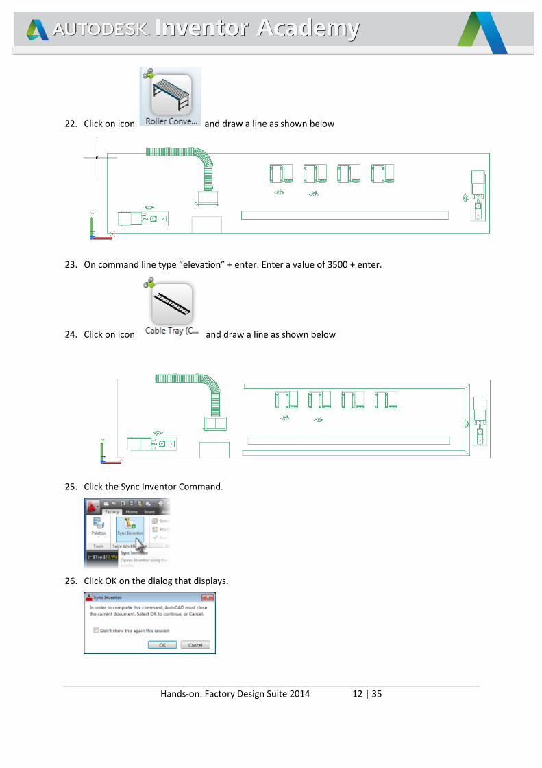
20. Open this library folder in the Asset Browser
21. Drag and drop Assets from the Asset Library into the layout as shown below
Hands-on: Factory Design Suite 2014 12 | 35
22. Click on icon and draw a line as shown below
23. On command line type “elevation” + enter. Enter a value of 3500 + enter.
24. Click on icon and draw a line as shown below
25. Click the Sync Inventor Command.
26. Click OK on the dialog that displays.
Hands-on: Factory Design Suite 2014 13 | 35
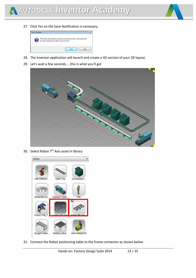
27. Click Yes on the Save Notification is necessary.
28. The Inventor application will launch and create a 3D version of your 2D layout.
29. Let’s wait a few seconds ….this is what you’ll get
30. Select Robot 7th Axis asset in library
31. Connect the Robot positioning table to the frame connector as shown below
Hands-on: Factory Design Suite 2014 14 | 35
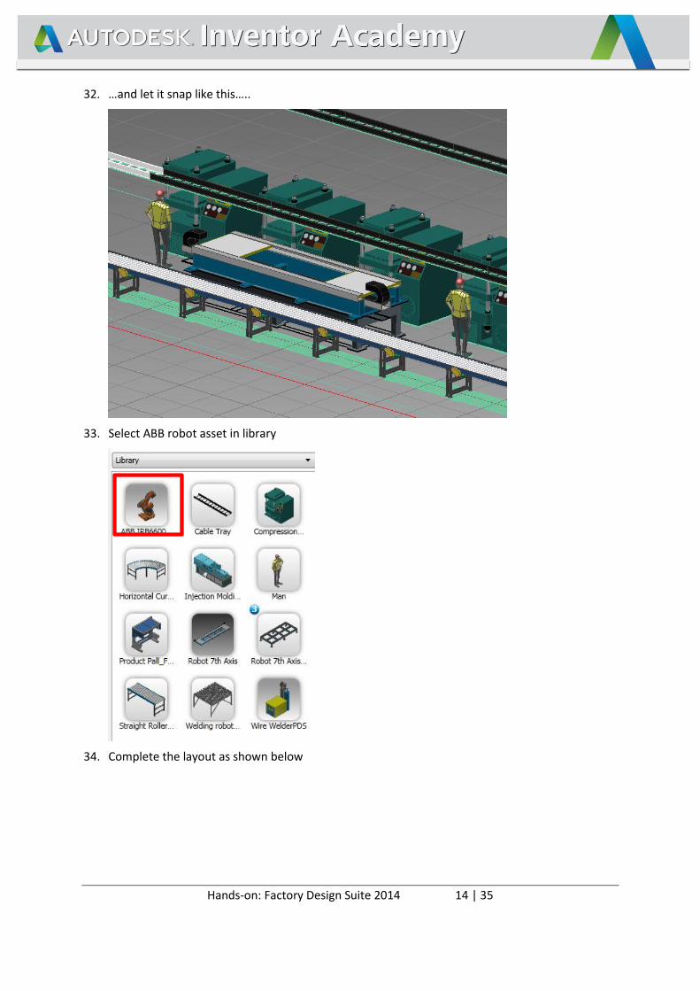
32. …and let it snap like this…..
33. Select ABB robot asset in library
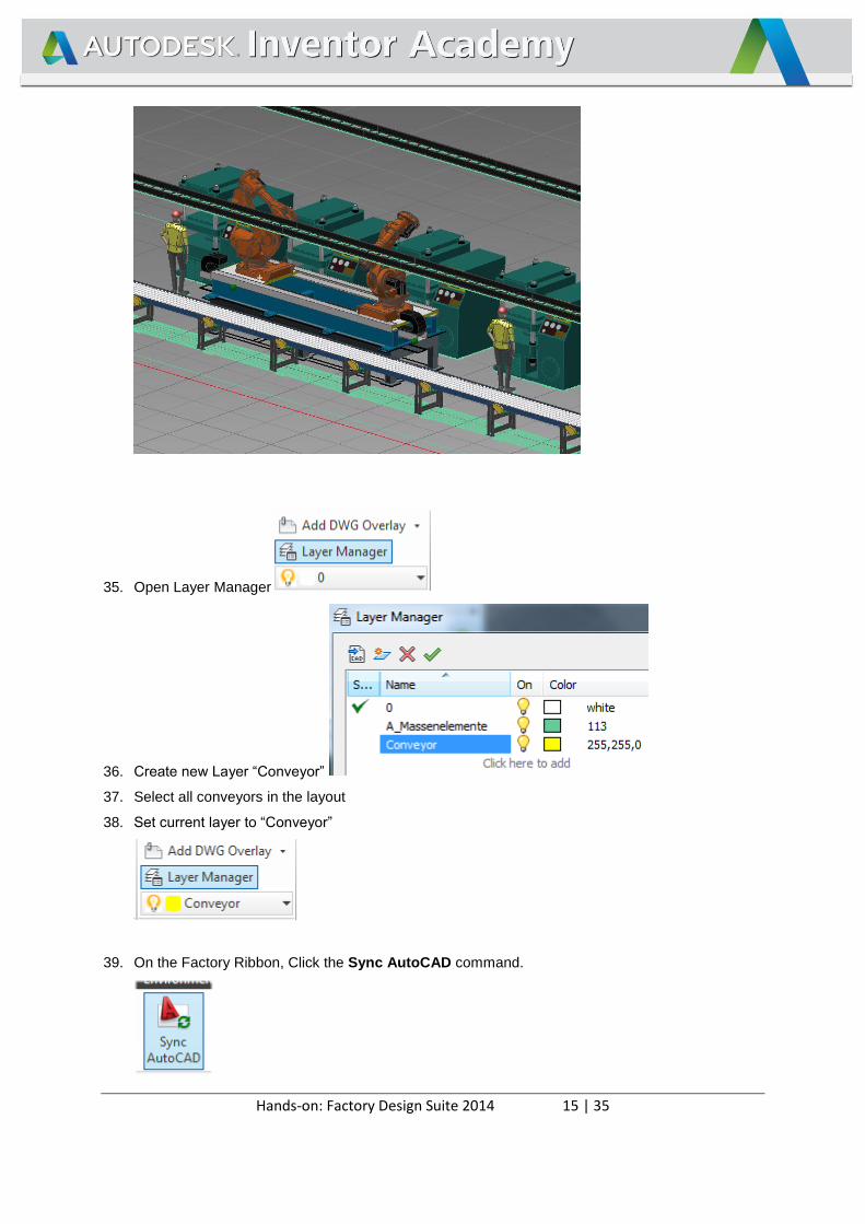
34. Complete the layout as shown below
Hands-on: Factory Design Suite 2014 15 | 35
35. Open Layer Manager
36. Create new Layer “Conveyor”
37. Select all conveyors in the layout
38. Set current layer to “Conveyor”
39. On the Factory Ribbon, Click the Sync AutoCAD command.
Hands-on: Factory Design Suite 2014 16 | 35
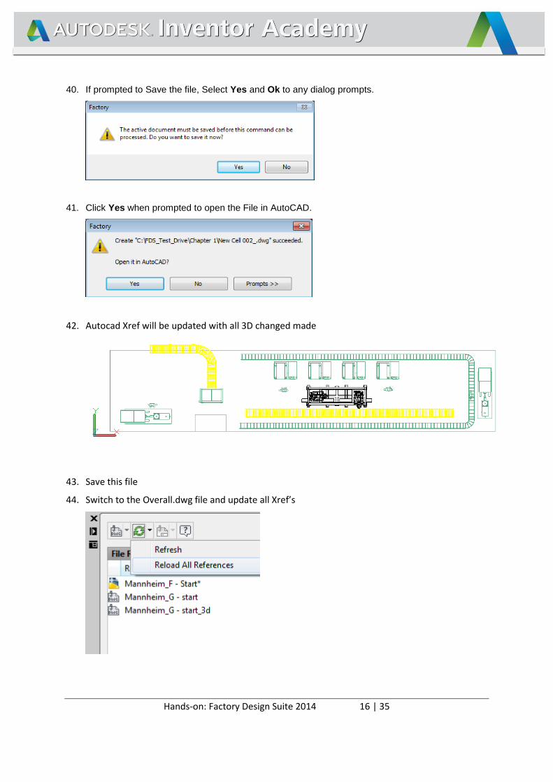
40. If prompted to Save the file, Select Yes and Ok to any dialog prompts.
41. Click Yes when prompted to open the File in AutoCAD.
42. Autocad Xref will be updated with all 3D changed made
43. Save this file
44. Switch to the Overall.dwg file and update all Xref’s
Hands-on: Factory Design Suite 2014 17 | 35
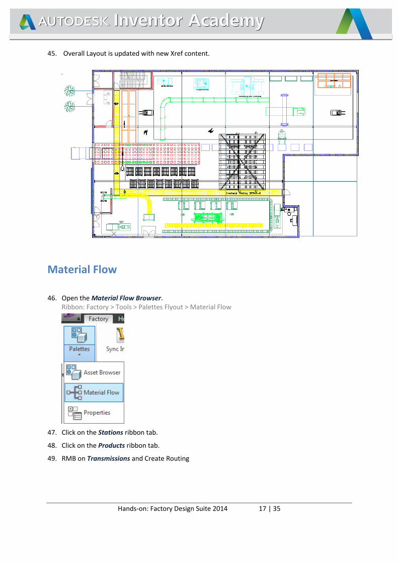
45. Overall Layout is updated with new Xref content.
Material Flow
46. Open the Material Flow Browser. Ribbon: Factory > Tools > Palettes Flyout > Material Flow
47. Click on the Stations ribbon tab.
48. Click on the Products ribbon tab.
49. RMB on Transmissions and Create Routing

Hands-on: Factory Design Suite 2014 18 | 35
50. Select stations as shown below
51. Routings tab should look like this
52. In Factory Ribbon, slelect Transportation tab
53. Result should look like this
Hands-on: Factory Design Suite 2014 19 | 35
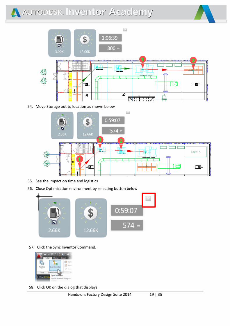
54. Move Storage out to location as shown below
55. See the impact on time and logistics
56. Close Optimization environment by selecting button below
57. Click the Sync Inventor Command.
58. Click OK on the dialog that displays.
Hands-on: Factory Design Suite 2014 20 | 35
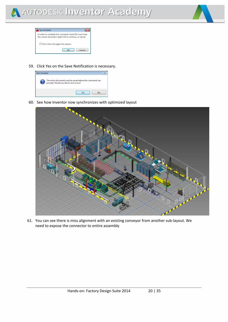
59. Click Yes on the Save Notification is necessary.
60. See how Inventor now synchronizes with optimized layout
61. You can see there is miss alignment with an existing conveyor from another sub-layout. We need to expose the connector to entire assembly
Hands-on: Factory Design Suite 2014 21 | 35
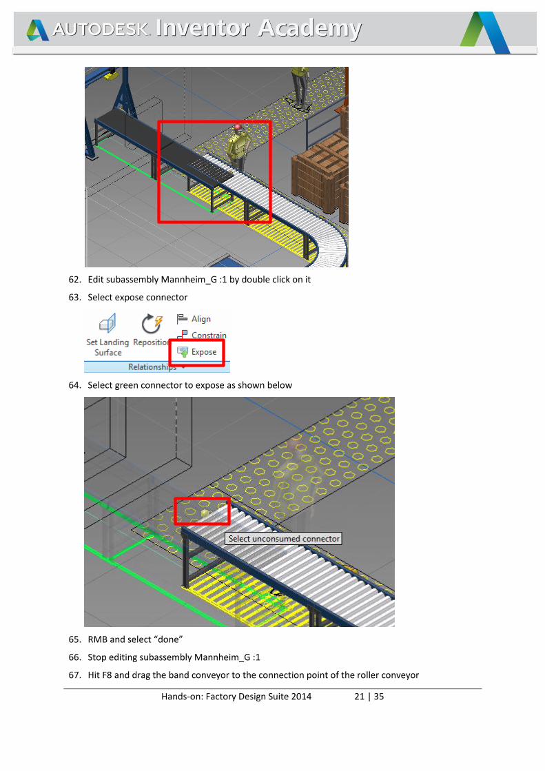
62. Edit subassembly Mannheim_G :1 by double click on it
63. Select expose connector
64. Select green connector to expose as shown below
65. RMB and select “done”
66. Stop editing subassembly Mannheim_G :1
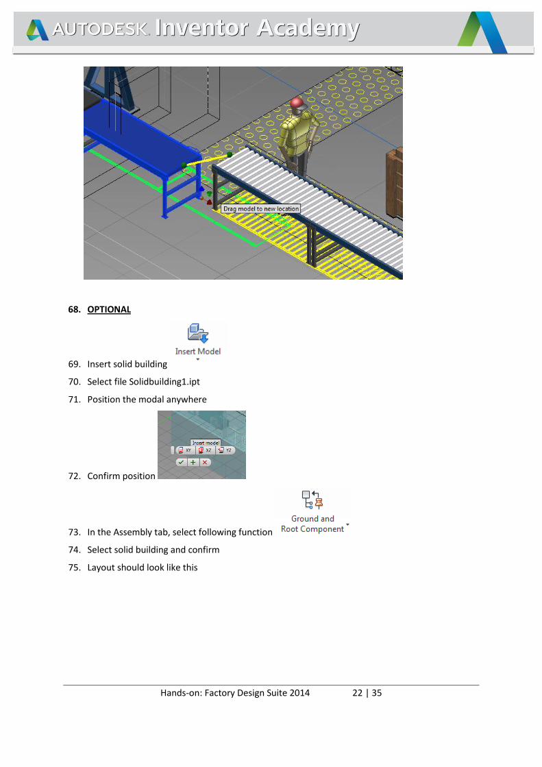
67. Hit F8 and drag the band conveyor to the connection point of the roller conveyor
Hands-on: Factory Design Suite 2014 22 | 35
68. OPTIONAL
69. Insert solid building
70. Select file Solidbuilding1.ipt
71. Position the modal anywhere
72. Confirm position
73. In the Assembly tab, select following function
74. Select solid building and confirm
75. Layout should look like this
Hands-on: Factory Design Suite 2014 23 | 35
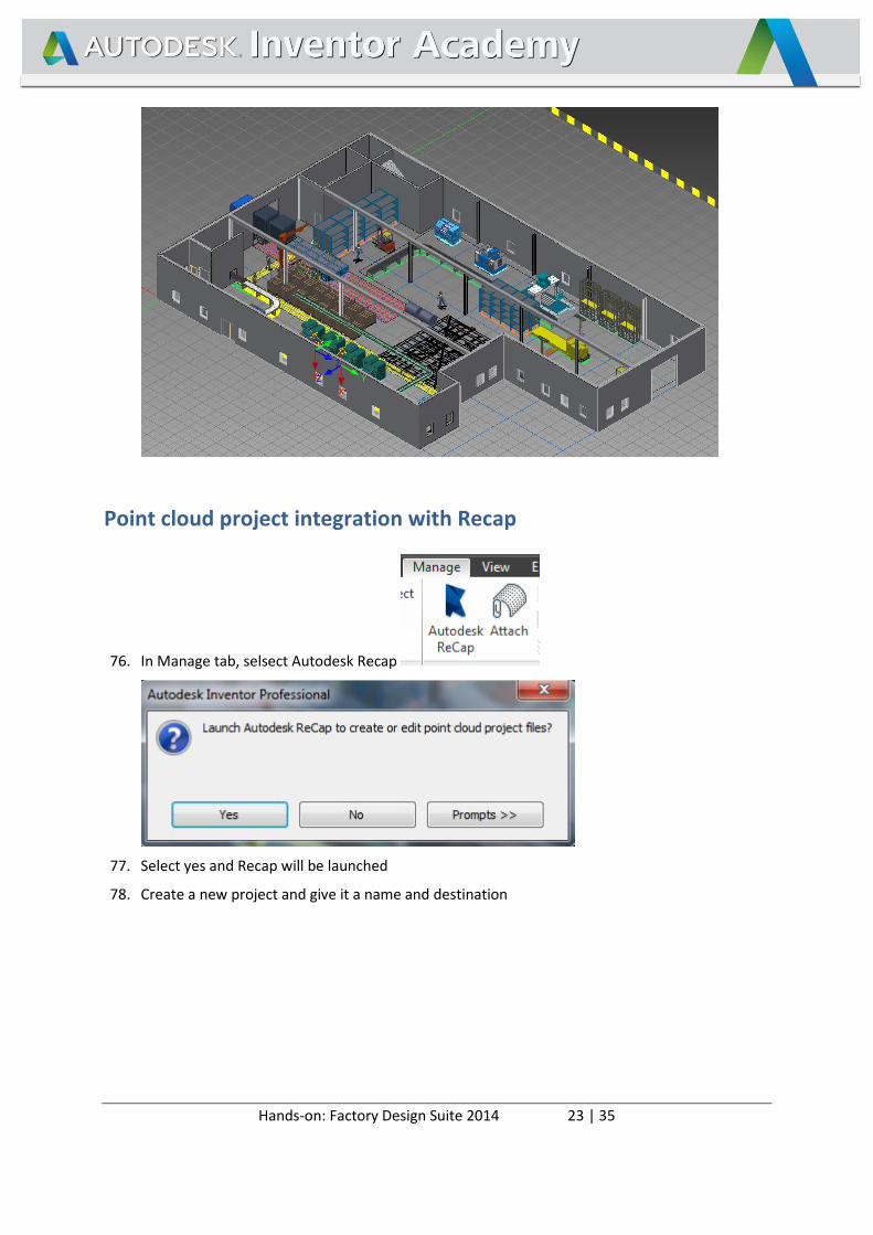
Point cloud project integration with Recap
76. In Manage tab, selsect Autodesk Recap
77. Select yes and Recap will be launched
78. Create a new project and give it a name and destination
Hands-on: Factory Design Suite 2014 24 | 35
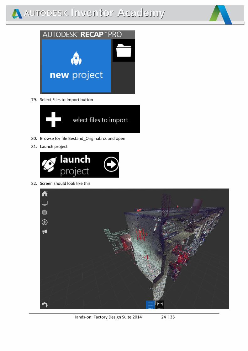
79. Select Files to Import button
80. Browse for file Bestand_Original.rcs and open
81. Launch project
82. Screen should look like this
Hands-on: Factory Design Suite 2014 25 | 35
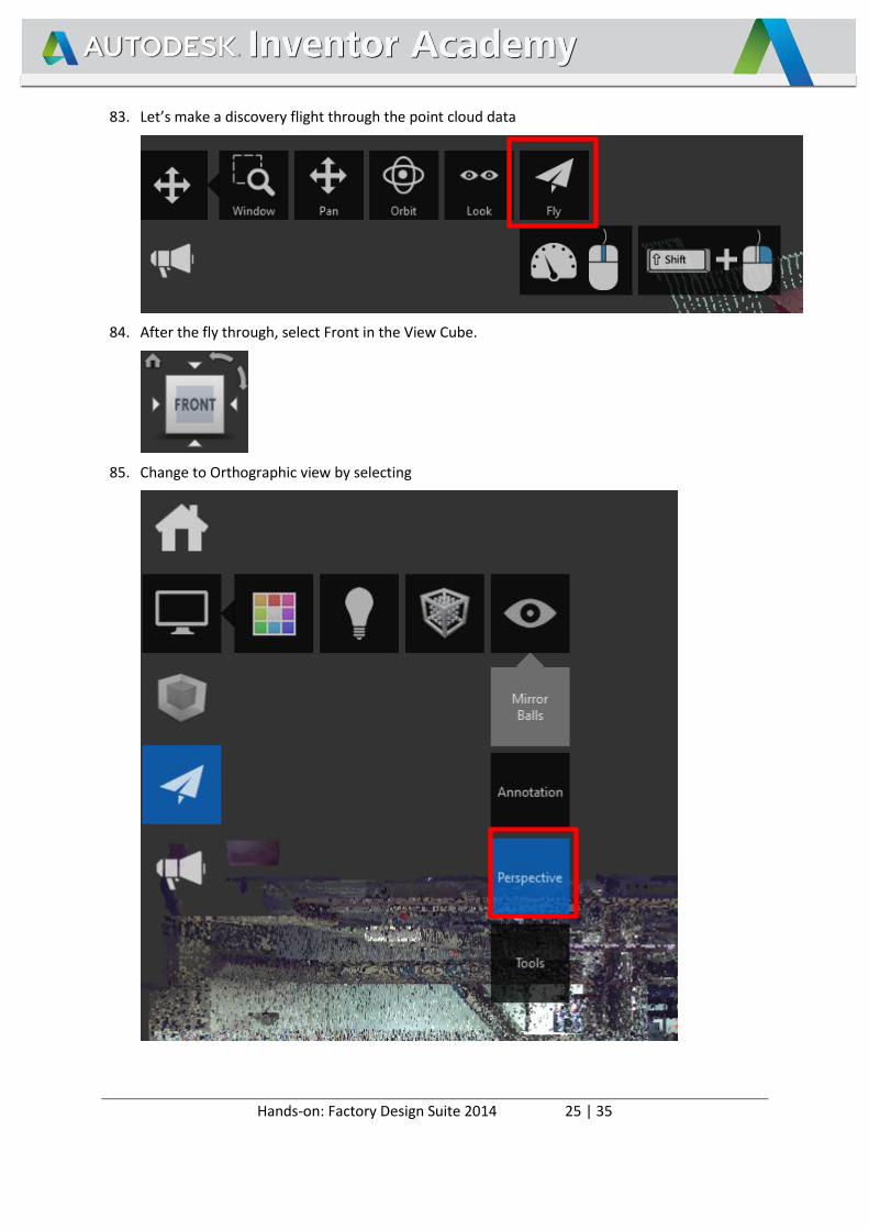
83. Let’s make a discovery flight through the point cloud data
84. After the fly through, select Front in the View Cube.
85. Change to Orthographic view by selecting
Hands-on: Factory Design Suite 2014 26 | 35
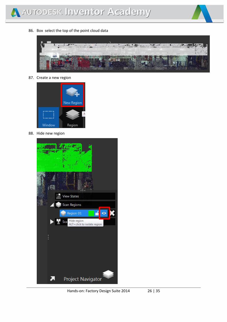
86. Box select the top of the point cloud data
87. Create a new region
88. Hide new region
Hands-on: Factory Design Suite 2014 27 | 35
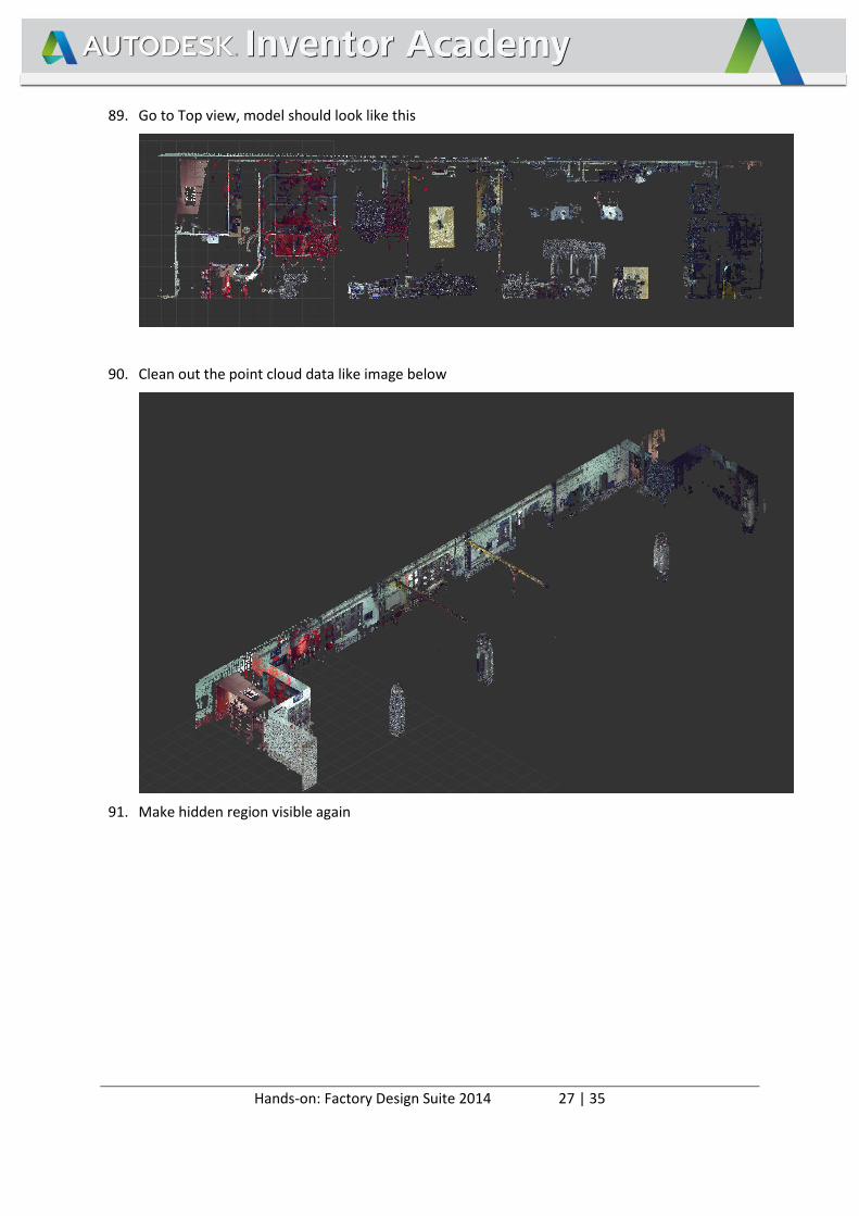
89. Go to Top view, model should look like this
90. Clean out the point cloud data like image below
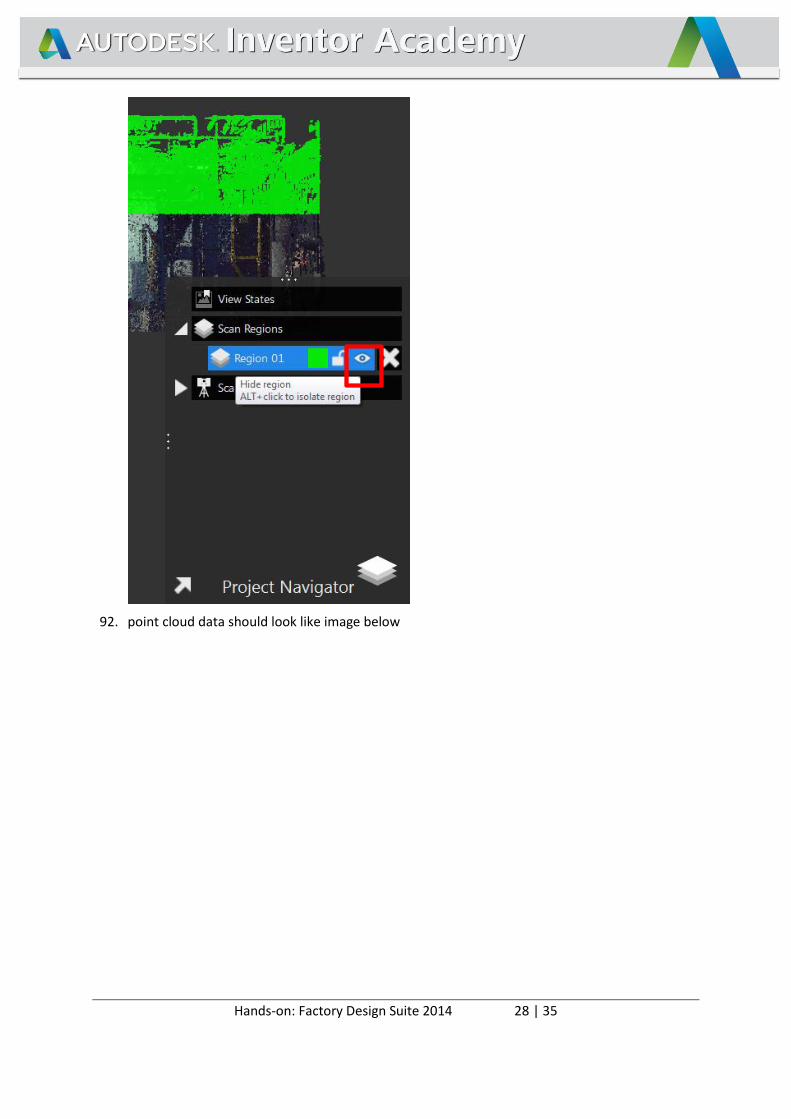
91. Make hidden region visible again
Hands-on: Factory Design Suite 2014 28 | 35
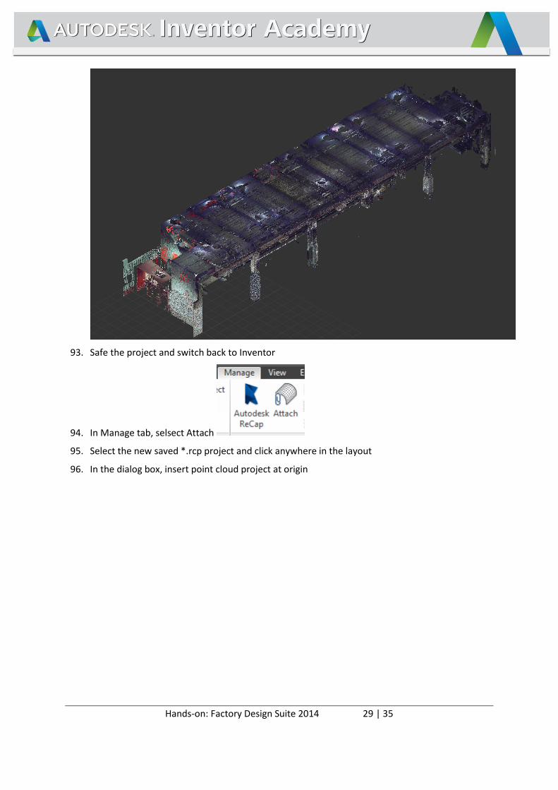
92. point cloud data should look like image below
Hands-on: Factory Design Suite 2014 29 | 35
93. Safe the project and switch back to Inventor
94. In Manage tab, selsect Attach
95. Select the new saved *.rcp project and click anywhere in the layout
96. In the dialog box, insert point cloud project at origin
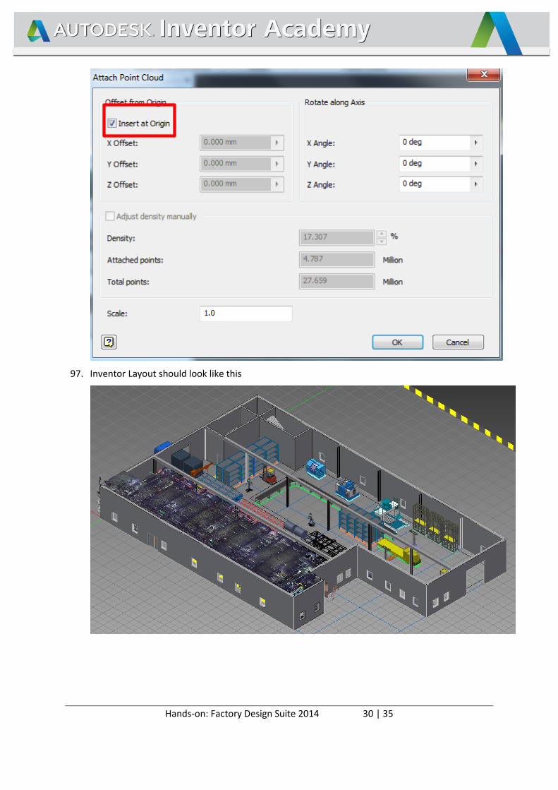
Hands-on: Factory Design Suite 2014 30 | 35
97. Inventor Layout should look like this

Hands-on: Factory Design Suite 2014 31 | 35
Project Overview Navisworks
98. Open the application NavisWorks Manage
99. Open the file <FDS-ROOT>\AIA2013\FDS Handson\Production Area\Factory_2014_Planning\ Mannheim_F - Start.nwd
100. In the viewpoint ribbon, select “Start” viewpoint
101. Walk around and look around in the facility.
Hands-on: Factory Design Suite 2014 32 | 35
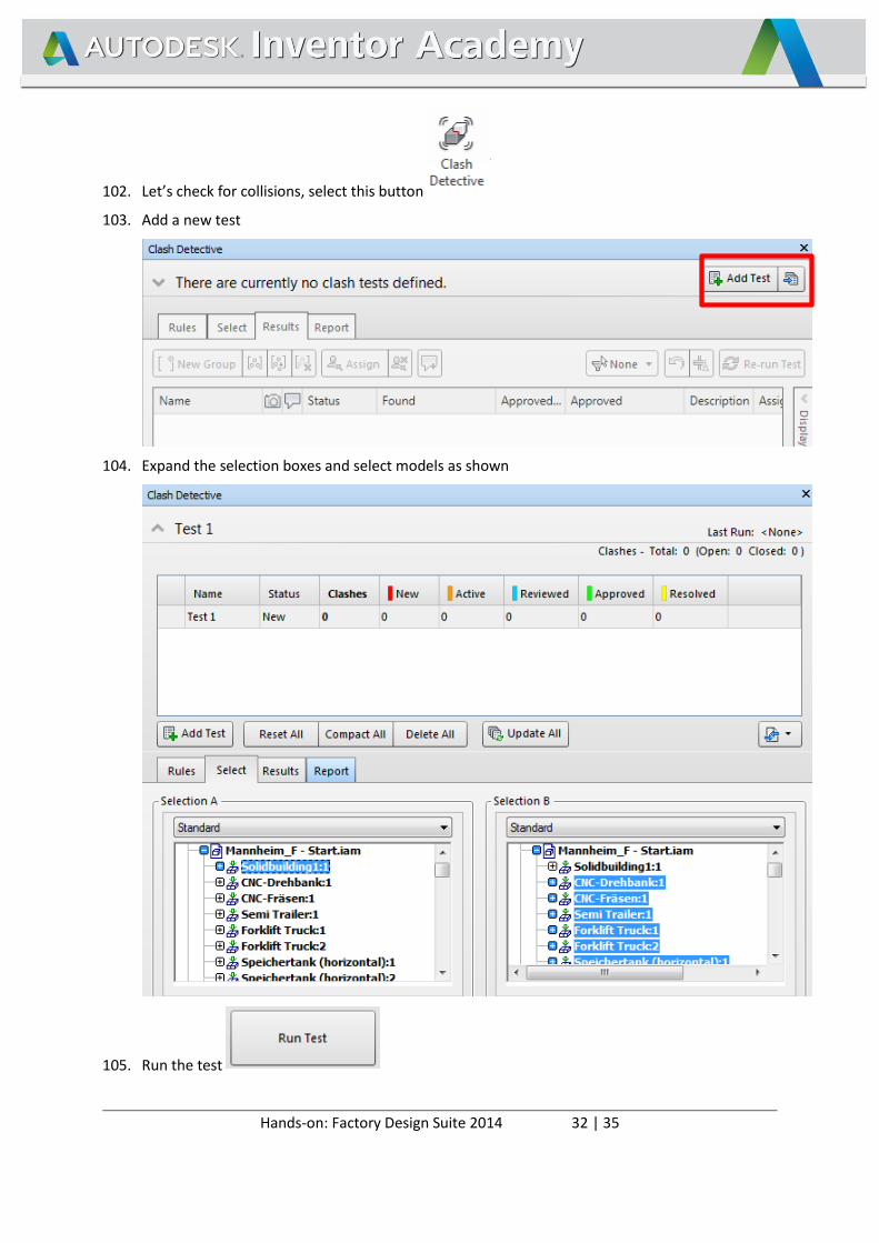
102. Let’s check for collisions, select this button
103. Add a new test
104. Expand the selection boxes and select models as shown
105. Run the test
Hands-on: Factory Design Suite 2014 33 | 35
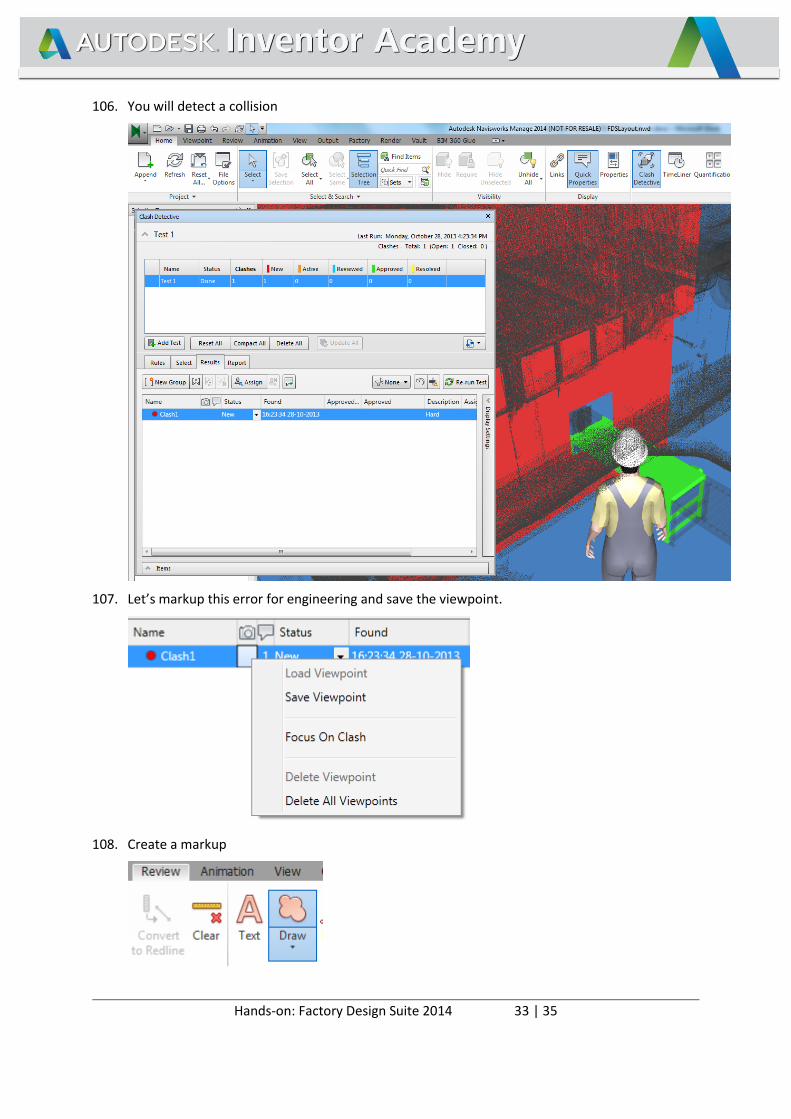
106. You will detect a collision
107. Let’s markup this error for engineering and save the viewpoint.
108. Create a markup
Hands-on: Factory Design Suite 2014 34 | 35
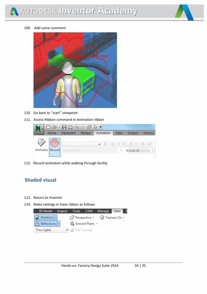
109. Add some comment
110. Go back to “start” viewpoint
111. Access Ribbon command in Animation ribbon
112. Record animation while walking through facility
Shaded visual
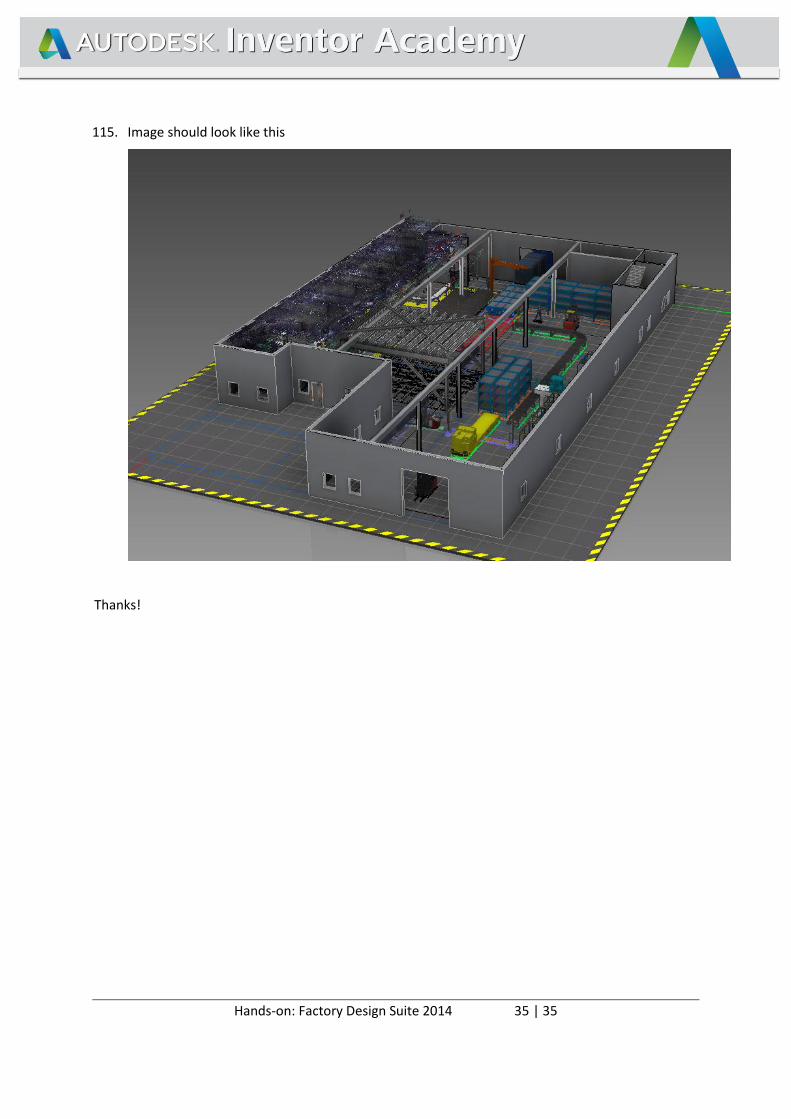
113. Return to Inventor
114. Make settings in View ribbon as follows
Hands-on: Factory Design Suite 2014 35 | 35
115. Image should look like this
Thanks!