Embed Size (px)
DESCRIPTION
Harbor Freight 3 HP Twin Tank Air Compressor 94734
Citation preview
3 HP TWIN TANKAIR COMPRESSOR
ASSEMBLY AND OPERATING INSTRUCTIONS
3491 Mission Oaks Blvd., Camarillo, CA 93011Visit our Web site at http://www.harborfreight.com
Copyright© 2006 by Harbor Freight Tools®. All rights reserved. No portion of thismanual or any artwork contained herein may be reproduced in any shape orform without the express written consent of Harbor Freight Tools.
For technical questions and replacement parts, please call 1-800-444-3353
94734
Due to continuing improvements, actual productmay differ slightly from the product described herein.
SKU 94734 For technical questions, please call 1-800-444-3353. Page 2
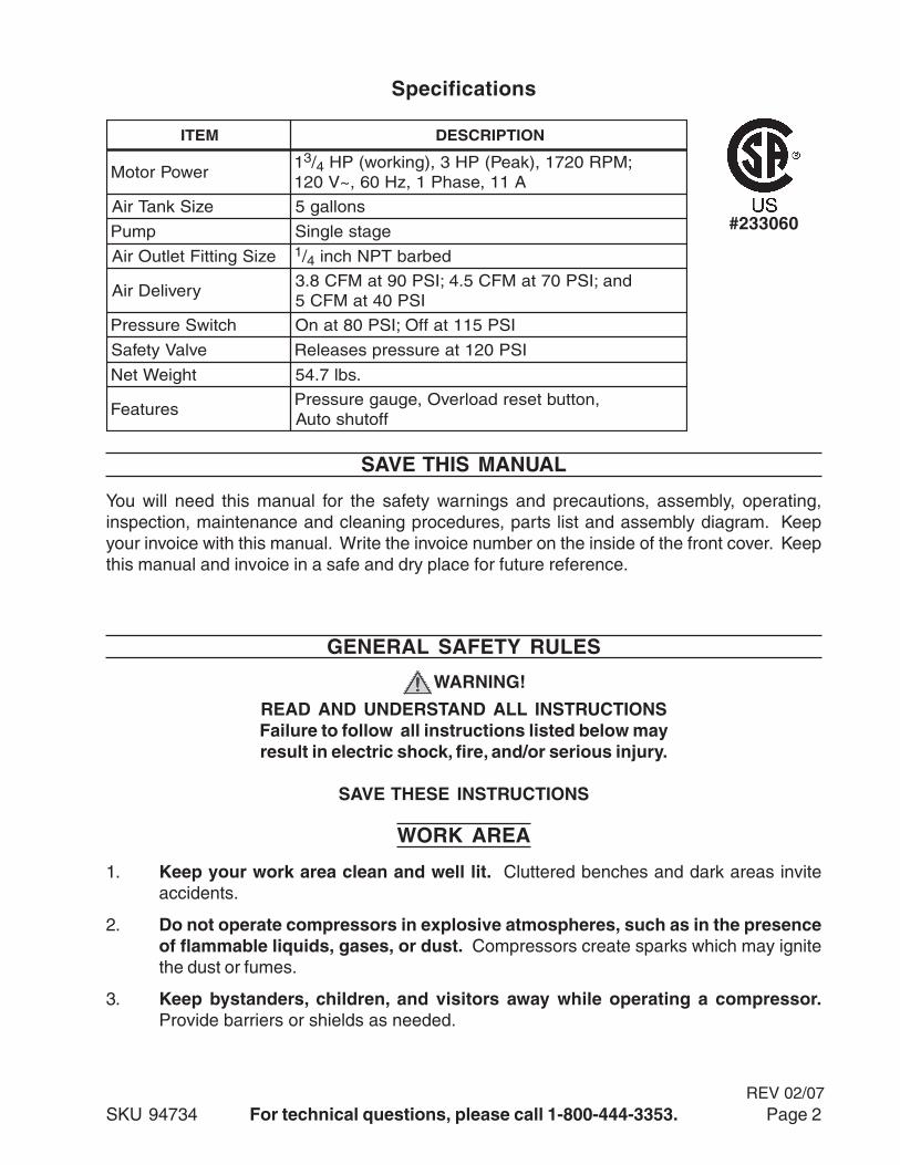
Specifications
METI NOITPIRCSED
rewoProtoM13/4 ;MPR0271,)kaeP(PH3,)gnikrow(PH
A11,esahP1,zH06,~V021
eziSknaTriA snollag5
pmuP egatselgniS
eziSgnittiFteltuOriA 1/4 debrabTPNhcni
yrevileDriAdna;ISP07taMFC5.4;ISP09taMFC8.3
ISP04taMFC5
hctiwSerusserP ISP511taffO;ISP08tanO
evlaVytefaS ISP021taerusserpsesaeleR
thgieWteN .sbl7.45
serutaeF,nottubteserdaolrevO,eguagerusserP
ffotuhsotuA
GENERAL SAFETY RULES
WARNING!
READ AND UNDERSTAND ALL INSTRUCTIONSFailure to follow all instructions listed below mayresult in electric shock, fire, and/or serious injury.
SAVE THESE INSTRUCTIONS
WORK AREA
1. Keep your work area clean and well lit. Cluttered benches and dark areas inviteaccidents.
2. Do not operate compressors in explosive atmospheres, such as in the presenceof flammable liquids, gases, or dust. Compressors create sparks which may ignitethe dust or fumes.
3. Keep bystanders, children, and visitors away while operating a compressor.Provide barriers or shields as needed.
#233060
You will need this manual for the safety warnings and precautions, assembly, operating,inspection, maintenance and cleaning procedures, parts list and assembly diagram. Keepyour invoice with this manual. Write the invoice number on the inside of the front cover. Keepthis manual and invoice in a safe and dry place for future reference.
SAVE THIS MANUAL
REV 02/07
SKU 94734 For technical questions, please call 1-800-444-3353. Page 3
ELECTRICAL SAFETY
1. Grounded compressors must be plugged into an outlet properly installed andgrounded in accordance with all codes and ordinances. Never remove thegrounding prong or modify the plug in any way. Do not use any adapter plugs.Check with a qualified electrician if you are in doubt as to whether the outlet isproperly grounded. If the compressors should electrically malfunction or break down,grounding provides a low resistance path to carry electricity away from the user.
2. Do not expose compressors to rain or wet conditions. Water entering an electricmotor will increase the risk of electric shock.
3. Do not abuse the Power Cord. Never use the Power Cord to pull the Plug from anoutlet. Keep the Power Cord away from heat, oil, sharp edges, or moving parts.Replace damaged Power Cords immediately. Damaged Power Cords increase therisk of electric shock.
4. AN EXTENSION CORD MUST NEVER BE USED WITH THIS ITEM. Connectingthis item to an outlet through an extension cord MAY CAUSE ELECTRICALDAMAGE TO THE MOTOR and could present a FIRE HAZARD.
5. Always unplug the air compressor, and release the air pressure when not in use.
PERSONAL SAFETY
1. Stay alert. Watch what you are doing, and use common sense during use. Do notuse while tired or under the influence of drugs, alcohol, or medication. A momentof inattention while operating may result in serious personal injury.
2. Dress properly. Do not wear loose clothing or jewelry. Contain long hair. Keepyour hair, clothing, and gloves away from moving parts. Loose clothes, jewelry, orlong hair can be caught in moving parts.
3. Avoid accidental starting. Be sure the Power Switch is turned off before pluggingin. Plugging in compressors with the Power Switch on, invites accidents.
4. Remove adjusting keys or wrenches before turning the compressor on. A wrenchor a key that is left attached to a rotating part of the compressor may result in personalinjury.
5. Do not overreach. Keep proper footing and balance at all times.
6. Use safety equipment. Always wear eye protection. Make sure you are wearingyour protective clothing, safety glasses with side shields and dust mask or air respirator,if appropriate.
SKU 94734 For technical questions, please call 1-800-444-3353. Page 4
TOOL USE AND CARE
1. Do not force the compressor. Use the correct compressor for your application.The correct compressor will do the job better and safer at the rate for which it is designed.Never attempt to force the compressor to provide more pressure than it was designedfor.
2. Do not use the compressor if the Power Switch does not turn it on or turn it off.Any compressor that cannot be controlled with the Power Switch is dangerous andmust be repaired or replaced.
3. Disconnect the Power Cord Plug from the power source before making anyadjustments, changing accessories, or storing the compressor. Such preventivesafety measures reduce the risk of starting the compressor accidentally.
4. Keep idle compressors out of reach of children and other untrained persons.Compressors are dangerous in the hands of untrained users.
5. Maintain compressors with care. Keep all components of this product clean anddry. Do not use a damaged compressor. Tag damaged compressors “Do not use” untilrepaired.
6. Check for misalignment or binding of moving parts, breakage of parts, and anyother condition that may affect the compressor’s operation. If damaged, have thecompressor serviced before using. Many accidents are caused by poorly maintainedcompressors.
7. Use only accessories that are recommended by the manufacturer for your model.Accessories that may be suitable for one compressor may become hazardous whenused on another compressor.
SERVICE
1. Compressor service must be performed only by qualified repair personnel. Serviceor maintenance performed by unqualified personnel could result in a risk of injury.
2. When servicing a compressor, use only identical replacement parts. Followinstructions in the “Inspection, Maintenance, And Cleaning” section of this manual.Use of unauthorized parts or failure to follow maintenance instructions may create arisk of electric shock or injury.
SPECIFIC SAFETY RULES
1. CAUTION! Prior to its first use, and thereafter prior to each subsequent use, makesure to fill the Air Compressor with a premium quality, 30 weight, non-detergentcompressor oil to the specified level. Running the Air Compressor with no oil or withlow oil will cause damage to the equipment and void its warranty. Refer to the “Setup”instructions on page 7 for details on filling the Air Compressor with oil.
2. When filling the Air Compressor with oil, make sure to unscrew (do not pull) theOil Fill Cap to remove.
SKU 94734 For technical questions, please call 1-800-444-3353. Page 5
3. Use eye and ear protection. Always wear ANSI-approved safety impact eye goggles,and ear plugs when using the Air Compressor.
4. Make sure all tools and equipment used with the Air Compressor are rated to theappropriate air pressure capacity of the Air Compressor. Do not use any tool orequipment that does not operate from 0-120 PSI. If necessary, check the owner’s manualof the tool or equipment for its air pressure rating.
5. Always disconnect the Air Compressor from its electrical outlet, release anyremaining air pressure from the unit, and disconnect all pneumatic tools andequipment from the unit, before performing any services or maintenance, or whennot in use.
6. Avoid injury. Never direct the air jet at people or animals.
7. Inspect safety valve daily. If the safety valve is not working properly, tank pressure canbuild up to dangerous levels. The tank could explode. For this reason, pull the ring onthe safety valve before each use and verify that it operates freely. Replace safety valveif it does not operate freely.Never remove or alter the factory sealed Safety Release Valve.
8. Do not attempt to readjust the automatic start and shutoff valves. Any change tothe automatic ON/OFF pressure levels will cause additional stress on the motor, whichmay result in shortened motor life.
9. Drain the Air Compressor’s air tank every day. Do not allow moisture to build upinside the Air Tank.
10. Do not unscrew the tank drain valve so that more than four threads are showing.
11. Avoid risk of tank explosion.a) Avoid weakening of tank by draining condensation after each use.b) Never modify tank by drilling holes, welding to it, or modifying it’s parts.c) The tank is designed, and factory set, to operate within a specific pressure range.
For that reason, never make adjustments to, or substitute parts, to the compressor.
12. Avoid bodily injury from moving parts. The compressor cycles on automatically,without notice. For this reason, always keep hands and arms away from compressorparts when the unit is connected to electrical power. Always have compressor safetyguards in place before turning compressor on.
13. Use approved air hose. Never use plastic or PVC pipe (unless specified for AirCompressors) to carry air under pressure. Regardless of its pressure rating, it can burstunder pressure.
14. Never plug the power cord of this product into an electrical outlet while standingon a wet or damp surface.
15. THIS AIR COMPRESSOR MAY REQUIRE A DEDICATED ELECTRICAL CIRCUITAS THE AMPERAGE DRAW UNDER FULL LOAD, COMBINED WITH USE OF ANYOTHER ITEM, MAY OVERLOAD YOUR CIRCUIT.
16. Always turn off the Air Compressor in the event of a power failure.
REV 02/07
SKU 94734 For technical questions, please call 1-800-444-3353. Page 6
17. Performance of this Air Compressor may vary depending on variations in localline voltage.
18. Maintain labels and nameplates on the Air Compressor. These carry importantinformation. If unreadable or missing, contact Harbor Freight Tools for a replacement.
19. WARNING! People with pacemakers should consult their physician(s) before usingthis product. Electromagnetic fields in close proximity to a heart pacemaker could causeinterference to or failure of the pacemaker.
20. WARNING! The brass components of this product contain lead, a chemical knownto the State of California to cause birth defects (or other reproductive harm). (CaliforniaHealth & Safety code § 25249.5, et seq.)
21. WARNING! The warnings, precautions, and instructions discussed in this instructionmanual cannot cover all possible conditions and situations that may occur. It must beunderstood by the operator that common sense and caution are factors which cannotbe built into this product, but must be supplied by the operator.
SAVE THESE INSTRUCTIONS
SKU 94734 For technical questions, please call 1-800-444-3353. Page 7
SetupDipstick
Warning: Fill compressor with oil before using; running with NO OIL or with LOW OILwill void the warranty. The optimal capacity of the oil reservoir is 7.8 ounces of oil.
The Dipstick is used to determine if oil is needed. Never operate the compressor withoutsufficient oil. Use a 30 weight, non-detergent compressor oil. To check the oil:
1. Unscrew the Dipstick.
2. Check the level of the oil. There are two lines on the bottom of the Dipstick. The oillevel should be somewhere between the two lines, as high as possible.
3. Add oil through the Dipstick’s hole as necessary, but do not overfill. Always use a highgrade oil specially designed for air compressors. Never mix oils of different types.Never use a low quality oil which may not afford adequate lubrication.
4. Replace the Dipstick.
Install an Air Intake Filter and Hose (not included)
The filter and oiler (not supplied) are recommended but not mandatory for operation.
1. Remove and discard the plastic cap which covers the threaded hole at the top of theCylinder Case (B-6).
2. Screw the threaded part of the air filter assembly into the Cylinder Case until it isfirmly seated.
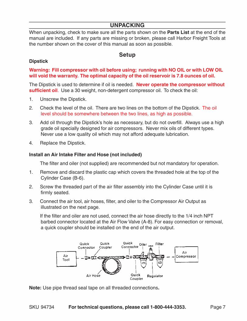
3. Connect the air tool, air hoses, filter, and oiler to the Compressor Air Output asillustrated on the next page.
If the filter and oiler are not used, connect the air hose directly to the 1/4 inch NPTbarbed connector located at the Air Flow Valve (A-8). For easy connection or removal,a quick coupler should be installed on the end of the air output.
Note: Use pipe thread seal tape on all threaded connections.
UNPACKINGWhen unpacking, check to make sure all the parts shown on the Parts List at the end of themanual are included. If any parts are missing or broken, please call Harbor Freight Tools atthe number shown on the cover of this manual as soon as possible.
SKU 94734 For technical questions, please call 1-800-444-3353. Page 8
Operation
Caution: Prior to use, inspect the compressor for any damaged parts or unsafe condi-tions. Make any necessary repairs before using again.
Turning Compressor On
1. Verify Tank Drain Valve (A-7) is closed.
2. Verify oil level is correct.
3. Verify that the Safety Valve (A-4) is operational.
4. Turn the Air Flow Valve (A-8) to the OFF position.
5. Plug the power cord into an electrical grounded 115 Volt AC electrical receptacle.
6. Rotate the Power Switch (A-5) to the Vertical position to turn the air compressor on.Rotate that same switch to the horizontal position to turn it off. See page 10.
NOTE: Allow the pressure to build up to at least 80 PSI before using air.
NOTE: Motor will not start if tank pressure is already between 80-115PSI. Pressure MUSTbe below 80PSI for motor to restart and build up pressure to the 115 PSI cut offpressure.
7. Open the Air Flow Valve (A-8) and check for air leaks.
The operation of the compressor is automatic, as controlled by the internal pressureswitch. When the pressure drops below its operating range the compressor turns on.When the pressure is above 115 PSI, the compressor shuts off.
Warning; The compressor will become very hot during operation. Do not touch the cyl-inder area of the compressor, or allow flammable materials to come in contact with thecylinder area.
Adjusting Pressure Gauge and Pressure Adjustment Screw
Caution: The Pressure Switch is adjustable but changes to the pressure levels are notrecommended; any change to the automatic ON/OFF pressure levels will cause addi-tional stress on the motor which may shorten motor life.
Adjusting Air Output
1. When the Air Flow Valve (A-8) is to the right or left, the valve is closed. When it is in themiddle, it is open.
2. Turn the Air Flow Valve to the appropriate pressure.
Maintenance
Warning: Do not make any repairs, adjustments, or maintenance on the air compressorunless it is disconnected from the electrical power and the tank pressure is released.
Maintenance should always be performed by a qualified technician.REV 02/07
SKU 94734 For technical questions, please call 1-800-444-3353. Page 9
1. Check the oil level before each use. If the oil is low, add some. If it is high, drain someby removing the Drain Plug. Replace the oil once a year.
2. Check and clean the Air Filter (B-5) every 50 hours, or sooner if used in a dustyenvironment.
3. Drain the air tanks after each use by opening the drain petcock or the Tank Drain Valve(A-7). Leave open until the next use.
4. After the compressor has cooled down, clean it with a damp rag containing milddetergent and water. Do not use flammable liquids or solvents.
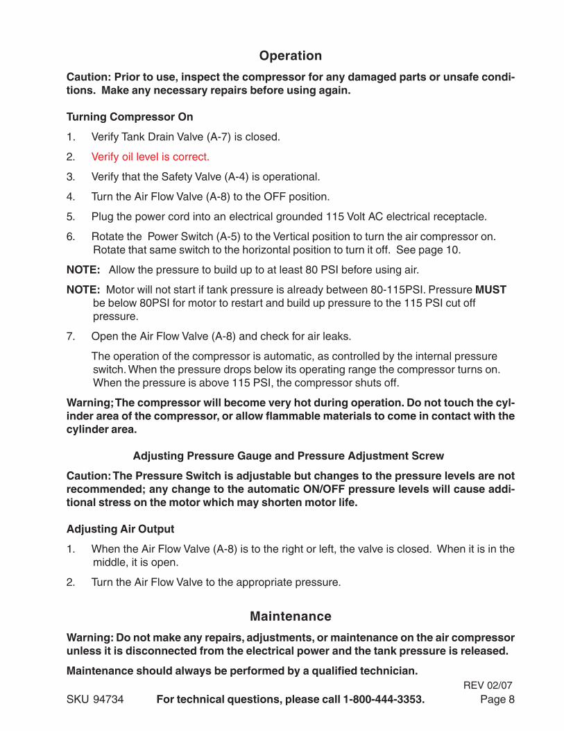
Parts List “A”
#metI noitpircseD ytQ
1-A ylbmessArosserpmoC 1
2-A eguaGerusserP 1
3-A pirGrebbuR 1
4-A evlaVytefaS 1
5-A hctiwSFFO/NO 1
6-A knaTriA 2
7-A evlaVniarDknaT 1
8-A evlaVwolFriA 1
9-A evlaVyaWenO 1
01-A ebuT 1
11-A esaB 1
21-A tooFrebbuR 1
31-A tuNdnatloB .ae1
NOTE: Some parts are listed and shown for illustration purposes only and are not availableindividually as replacement parts.
PLEASE READ THE FOLLOWING CAREFULLY
THE MANUFACTURER AND/OR DISTRIBUTOR HAS PROVIDED THE PARTS DIAGRAM IN THISMANUAL AS A REFERENCE TOOL ONLY. NEITHER THE MANUFACTURER NOR DISTRIBUTORMAKES ANY REPRESENTATION OR WARRANTY OF ANY KIND TO THE BUYER THAT HE ORSHE IS QUALIFIED TO MAKE ANY REPAIRS TO THE PRODUCT OR THAT HE OR SHE ISQUALIFIED TO REPLACE ANY PARTS OF THE PRODUCT. IN FACT, THE MANUFACTURERAND/OR DISTRIBUTOR EXPRESSLY STATES THAT ALL REPAIRS AND PARTS REPLACEMENTSSHOULD BE UNDERTAKEN BY CERTIFIED AND LICENSED TECHNICIANS AND NOT BY THEBUYER. THE BUYER ASSUMES ALL RISK AND LIABILITY ARISING OUT OF HIS OR HERREPAIRS TO THE ORIGINAL PRODUCT OR REPLACEMENT PARTS THERETO, OR ARISINGOUT OF HIS OR HER INSTALLATION OF REPLACEMENT PARTS THERETO.
SKU 94734 For technical questions, please call 1-800-444-3353. Page 10
A3
A5
A2
A11
A13A1
A6
A10
A12
A9
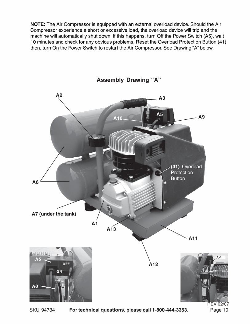
Assembly Drawing “A”
A7 (under the tank)
on
NOTE: The Air Compressor is equipped with an external overload device. Should the AirCompressor experience a short or excessive load, the overload device will trip and themachine will automatically shut down. If this happens, turn Off the Power Switch (A5), wait10 minutes and check for any obvious problems. Reset the Overload Protection Button (41)then, turn On the Power Switch to restart the Air Compressor. See Drawing “A” below.
(41) OverloadProtectionButton
REV 02/07
SKU 94734 For technical questions, please call 1-800-444-3353. Page 11
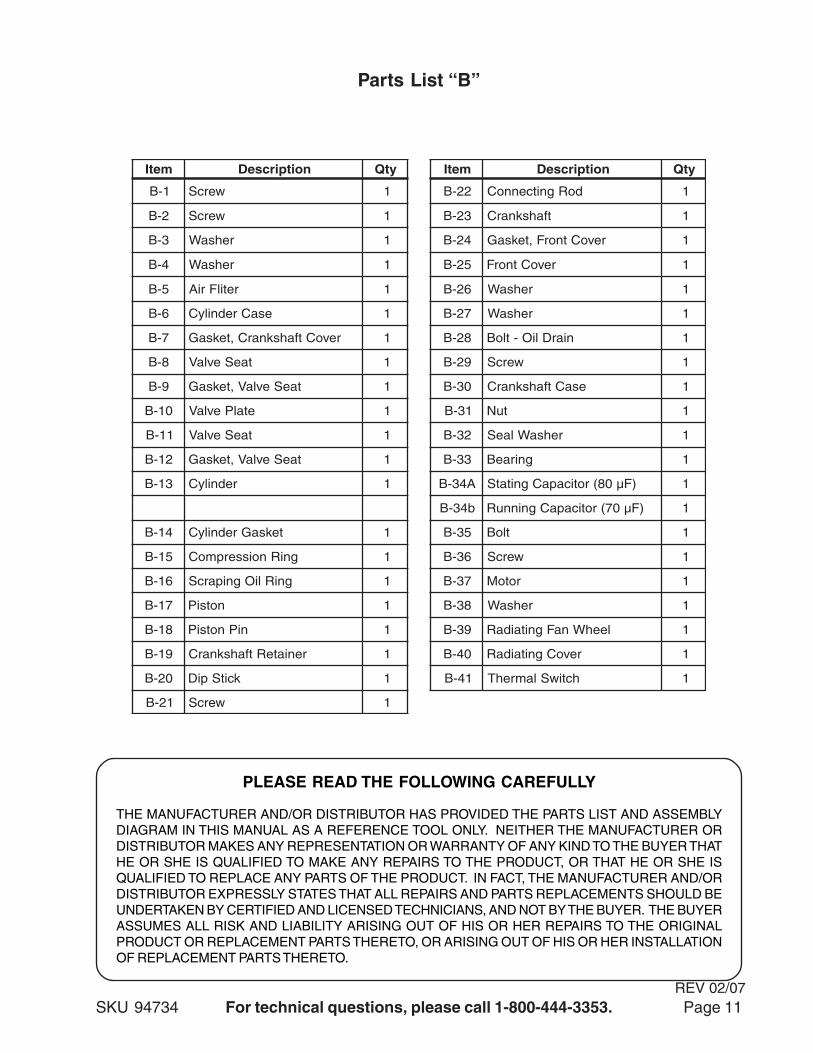
Parts List “B”
metI noitpircseD ytQ metI noitpircseD ytQ
1-B wercS 1 22-B doRgnitcennoC 1
2-B wercS 1 32-B tfahsknarC 1
3-B rehsaW 1 42-B revoCtnorF,teksaG 1
4-B rehsaW 1 52-B revoCtnorF 1
5-B retilFriA 1 62-B rehsaW 1
6-B esaCrednilyC 1 72-B rehsaW 1
7-B revoCtfahsknarC,teksaG 1 82-B niarDliO-tloB 1
8-B taeSevlaV 1 92-B wercS 1
9-B taeSevlaV,teksaG 1 03-B esaCtfahsknarC 1
01-B etalPevlaV 1 13-B tuN 1
11-B taeSevlaV 1 23-B rehsaWlaeS 1
21-B taeSevlaV,teksaG 1 33-B gniraeB 1
31-B rednilyC 1 A43-B )Fµ08(roticapaCgnitatS 1
b43-B )Fµ07(roticapaCgninnuR 1
41-B teksaGrednilyC 1 53-B tloB 1
51-B gniRnoisserpmoC 1 63-B wercS 1
61-B gniRliOgniparcS 1 73-B rotoM 1
71-B notsiP 1 83-B rehsaW 1
81-B niPnotsiP 1 93-B leehWnaFgnitaidaR 1
91-B reniateRtfahsknarC 1 04-B revoCgnitaidaR 1
02-B kcitSpiD 1 14-B hctiwSlamrehT 1
12-B wercS 1
PLEASE READ THE FOLLOWING CAREFULLY
THE MANUFACTURER AND/OR DISTRIBUTOR HAS PROVIDED THE PARTS LIST AND ASSEMBLYDIAGRAM IN THIS MANUAL AS A REFERENCE TOOL ONLY. NEITHER THE MANUFACTURER ORDISTRIBUTOR MAKES ANY REPRESENTATION OR WARRANTY OF ANY KIND TO THE BUYER THATHE OR SHE IS QUALIFIED TO MAKE ANY REPAIRS TO THE PRODUCT, OR THAT HE OR SHE ISQUALIFIED TO REPLACE ANY PARTS OF THE PRODUCT. IN FACT, THE MANUFACTURER AND/ORDISTRIBUTOR EXPRESSLY STATES THAT ALL REPAIRS AND PARTS REPLACEMENTS SHOULD BEUNDERTAKEN BY CERTIFIED AND LICENSED TECHNICIANS, AND NOT BY THE BUYER. THE BUYERASSUMES ALL RISK AND LIABILITY ARISING OUT OF HIS OR HER REPAIRS TO THE ORIGINALPRODUCT OR REPLACEMENT PARTS THERETO, OR ARISING OUT OF HIS OR HER INSTALLATIONOF REPLACEMENT PARTS THERETO.
REV 02/07
SKU 94734 For technical questions, please call 1-800-444-3353. Page 12
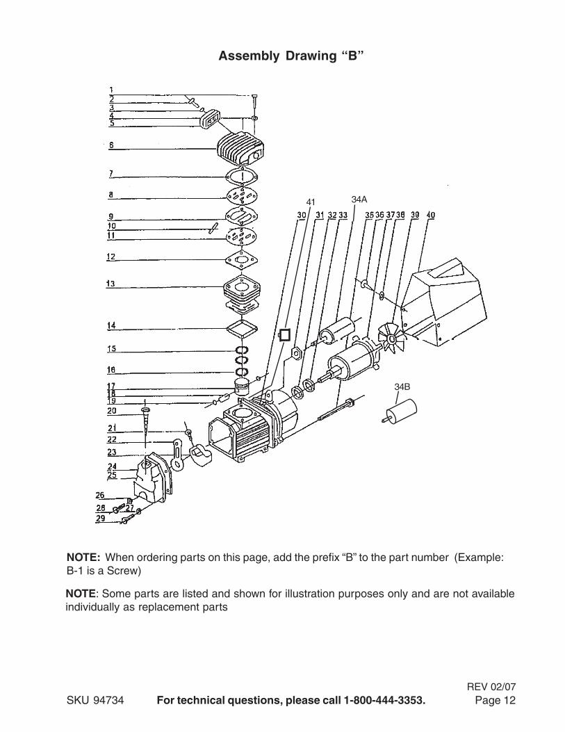
Assembly Drawing “B”
NOTE: When ordering parts on this page, add the prefix “B” to the part number (Example:B-1 is a Screw)
41
NOTE: Some parts are listed and shown for illustration purposes only and are not availableindividually as replacement parts
REV 02/07
34A
34B
SKU 94734 For technical questions, please call 1-800-444-3353. Page 13
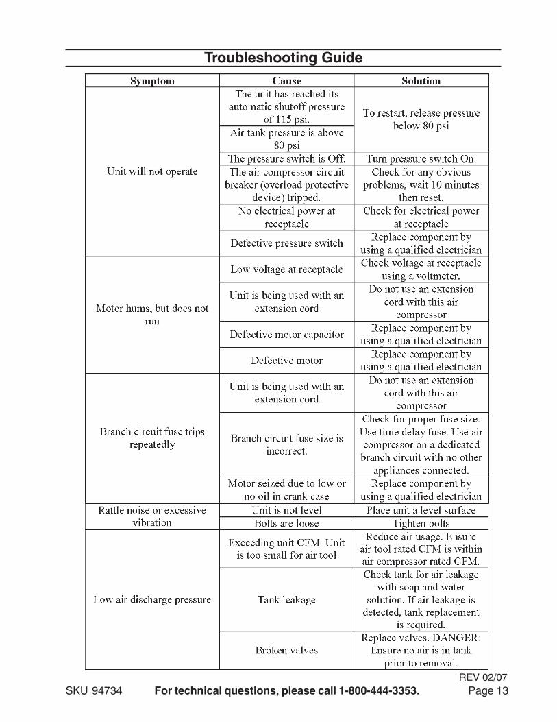
Troubleshooting Guide
REV 02/07
SKU 94734 For technical questions, please call 1-800-444-3353. Page 14
Troubleshooting Guide Continued
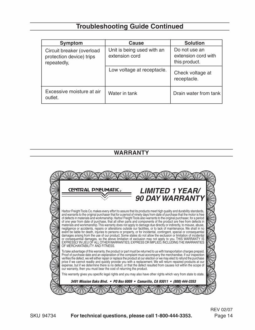
3491 Mission Oaks Blvd. • PO Box 6009 • Camarillo, CA 93011 • (800) 444-3353
Harbor Freight Tools Co. makes every effort to assure that its products meet high quality and durability standards, and warrants to the original purchaser that for a period of ninety days from date of purchase that the motor is free of defects in materials and workmanship. Harbor Freight Tools also warrants to the original purchaser, for a period of one year from date of purchase, that all other parts and components of the product are free from defects in materials and workmanship. This warranty does not apply to damage due directly or indirectly, to misuse, abuse, negligence or accidents, repairs or alterations outside our facilities, or to lack of maintenance. We shall in no event be liable for death, injuries to persons or property, or for incidental, contingent, special or consequential damages arising from the use of our product. Some states do not allow the exclusion or limitation of incidental or consequential damages, so the above limitation of exclusion may not apply to you. THIS WARRANTY IS EXPRESSLY IN LIEU OF ALL OTHER WARRANTIES, EXPRESS OR IMPLIED, INCLUDING THE WARRANTIES OF MERCHANTABILITY AND FITNESS.
To take advantage of this warranty, the product or part must be returned to us with transportation charges prepaid. Proof of purchase date and an explanation of the complaint must accompany the merchandise. If our inspection verifies the defect, we will either repair or replace the product at our election or we may elect to refund the purchase price if we cannot readily and quickly provide you with a replacement. We will return repaired products at our expense, but if we determine there is no defect, or that the defect resulted from causes not within the scope of our warranty, then you must bear the cost of returning the product.
This warranty gives you specific legal rights and you may also have other rights which vary from state to state.
LIMITED 1 YEAR/90 DAY WARRANTY
Symptom Cause Solution
Circuit breaker (overloadprotection device) tripsrepeatedly,
Unit is being used with anextension cord
Do not use anextension cord withthis product.
Low voltage at receptacle.Check voltage atreceptacle.
Excessive moisture at airoutlet.
Water in tank Drain water from tank
WARRANTY
REV 02/07


![[XLS]webbcounty.comwebbcounty.com/CountyAuditor/FinancialTransparency/Check... · Web viewLF ENTERPRISES frieght for tupperware bowls delivery tupperware bowls stock #458 to be used](https://img.pdfslide.net/doc/110x75/5b01aadd7f8b9a952f8ebaf7/xls-viewlf-enterprises-frieght-for-tupperware-bowls-delivery-tupperware-bowls.jpg)