Embed Size (px)
Citation preview

© 2012 The McGraw-Hill Companies, Inc. All rights reserved
Mike Meyers’ CompTIA A+®
Guide to
Managing and
Troubleshooting PCs
Fourth Edition
Hard Drive Technologies
Chapter 11
© 2012 The McGraw-Hill Companies, Inc. All rights reserved
Mike Meyers’ CompTIA A+®
Guide to
Managing and
Troubleshooting PCs
Fourth Edition
Overview
• In this chapter, you will learn how to
– Explain how hard drives work
– Identify and explain the PATA and SATA hard drive interfaces
– Identify and explain the SCSI hard drive interfaces
– Describe how to protect data with RAID
– Install hard drives
– Configure CMOS and install drivers
– Troubleshoot hard drive installation

© 2012 The McGraw-Hill Companies, Inc. All rights reserved
Mike Meyers’ CompTIA A+®
Guide to
Managing and
Troubleshooting PCs
Fourth Edition
How Hard Drives Work
Historical/Conceptual
© 2012 The McGraw-Hill Companies, Inc. All rights reserved
Mike Meyers’ CompTIA A+®
Guide to
Managing and
Troubleshooting PCs
Fourth Edition
The Platter-based Hard Drive
• A traditional hard disk drive (HDD) is composed of individual disks or platters.
• The platters are made up of aluminum and coated with a magnetic medium.
• Two tiny read/write heads service each platter.
© 2012 The McGraw-Hill Companies, Inc. All rights reserved
Mike Meyers’ CompTIA A+®
Guide to
Managing and
Troubleshooting PCs
Fourth Edition
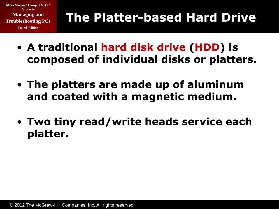
The Platter-based Hard Drive (continued)
Figure 1: Inside the hard drive
© 2012 The McGraw-Hill Companies, Inc. All rights reserved
Mike Meyers’ CompTIA A+®
Guide to
Managing and
Troubleshooting PCs
Fourth Edition
The Hard Drive
• The closer the read/write heads are to the platter, the more densely the data can be packed on to the drive.
• Hard drives use a tiny, heavily filtered aperture to equalize the air pressure between the exterior and interior of the hard drive.
• Platters spin between 3,500 and 15,000 revolutions per minute (RPM).

© 2012 The McGraw-Hill Companies, Inc. All rights reserved
Mike Meyers’ CompTIA A+®
Guide to
Managing and
Troubleshooting PCs
Fourth Edition
The Hard Drive (continued)
Figure 2: Read/write heads on actuator arms
© 2012 The McGraw-Hill Companies, Inc. All rights reserved
Mike Meyers’ CompTIA A+®
Guide to
Managing and
Troubleshooting PCs
Fourth Edition
Data Encoding
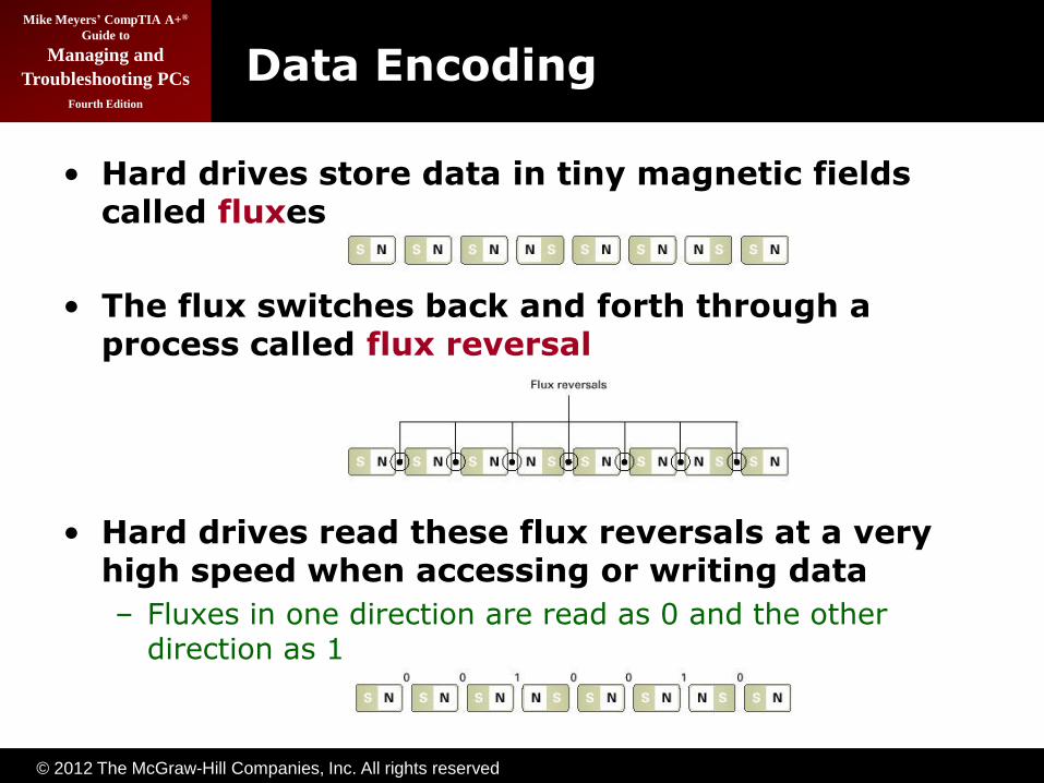
• Hard drives store data in tiny magnetic fields called fluxes
• The flux switches back and forth through a process called flux reversal
• Hard drives read these flux reversals at a very high speed when accessing or writing data
– Fluxes in one direction are read as 0 and the other direction as 1
© 2012 The McGraw-Hill Companies, Inc. All rights reserved
Mike Meyers’ CompTIA A+®
Guide to
Managing and
Troubleshooting PCs
Fourth Edition
Data Encoding (continued)
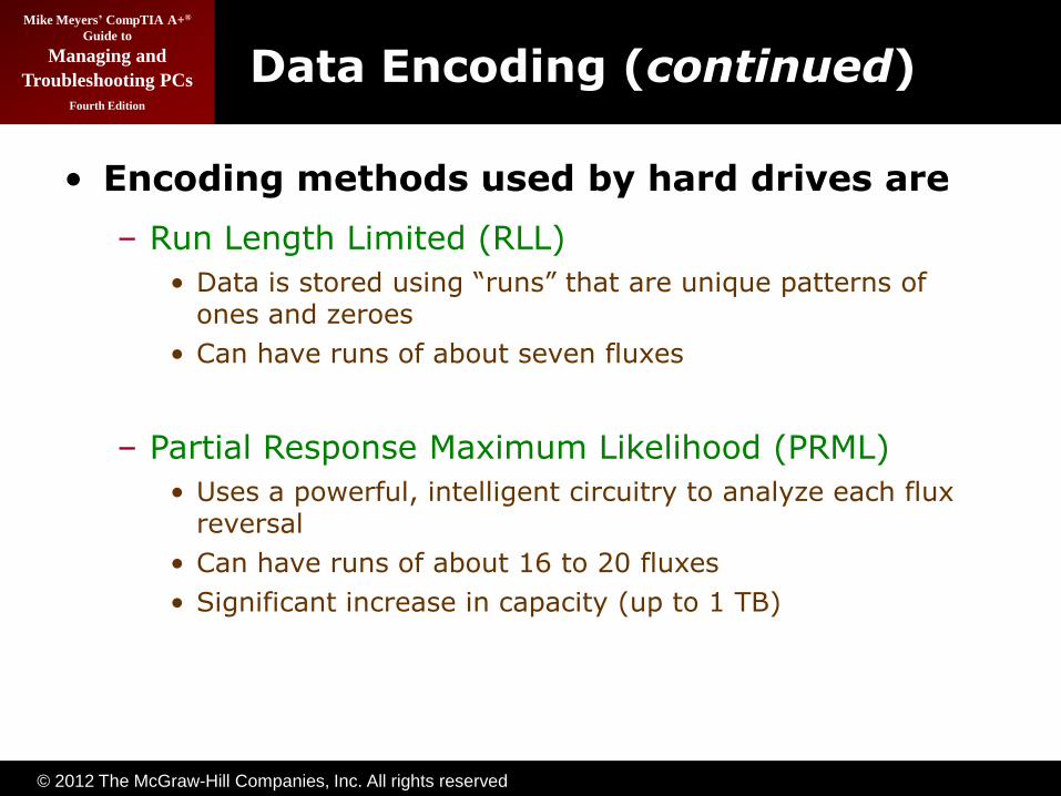
• Encoding methods used by hard drives are
– Run Length Limited (RLL)
• Data is stored using ―runs‖ that are unique patterns of ones and zeroes
• Can have runs of about seven fluxes
– Partial Response Maximum Likelihood (PRML)
• Uses a powerful, intelligent circuitry to analyze each flux reversal
• Can have runs of about 16 to 20 fluxes
• Significant increase in capacity (up to 1 TB)

© 2012 The McGraw-Hill Companies, Inc. All rights reserved
Mike Meyers’ CompTIA A+®
Guide to
Managing and
Troubleshooting PCs
Fourth Edition
• The stepper motor technology and the voice coil technology are used for moving the head actuator
– Moves the arms in fixed increments or steps
– Only seen in floppies today
• The voice coil technology uses a permanent magnet surrounding the coil on the head actuator to move the arm
– Automatically parks drive over non-data area when power removed
– This is how modern HDDs work
Arm Movement in the Hard Drive

© 2012 The McGraw-Hill Companies, Inc. All rights reserved
Mike Meyers’ CompTIA A+®
Guide to
Managing and
Troubleshooting PCs
Fourth Edition
Geometry
• Geometry is used to determine the location of the data on the hard drive
– CHS (cylinders, heads, sectors)
• Used to be critical to know geometry
– Had to enter into CMOS manually
• Today geometry stored on hard drive
– BIOS can query hard drive for geometry data

© 2012 The McGraw-Hill Companies, Inc. All rights reserved
Mike Meyers’ CompTIA A+®
Guide to
Managing and
Troubleshooting PCs
Fourth Edition
Heads
• Number of read/write heads used by the drive to store data
• Two heads per platter (top and bottom)
• Most hard drives have an extra head or two for their own usage, so the number may not be even
Figure 3: Two heads per platter
© 2012 The McGraw-Hill Companies, Inc. All rights reserved
Mike Meyers’ CompTIA A+®
Guide to
Managing and
Troubleshooting PCs
Fourth Edition
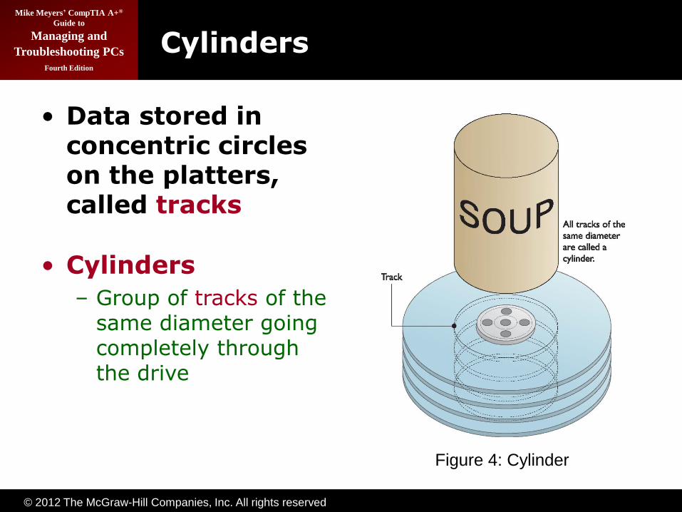
• Data stored in concentric circles on the platters, called tracks
• Cylinders
– Group of tracks of the same diameter going completely through the drive
Cylinders
Figure 4: Cylinder

© 2012 The McGraw-Hill Companies, Inc. All rights reserved
Mike Meyers’ CompTIA A+®
Guide to
Managing and
Troubleshooting PCs
Fourth Edition
Sectors per Track
• Number of slices in the hard drive
• 512 bytes of storage per sector
• Data is stored on the platters in sectors
Figure 5: Sectors per track
© 2012 The McGraw-Hill Companies, Inc. All rights reserved
Mike Meyers’ CompTIA A+®
Guide to
Managing and
Troubleshooting PCs
Fourth Edition
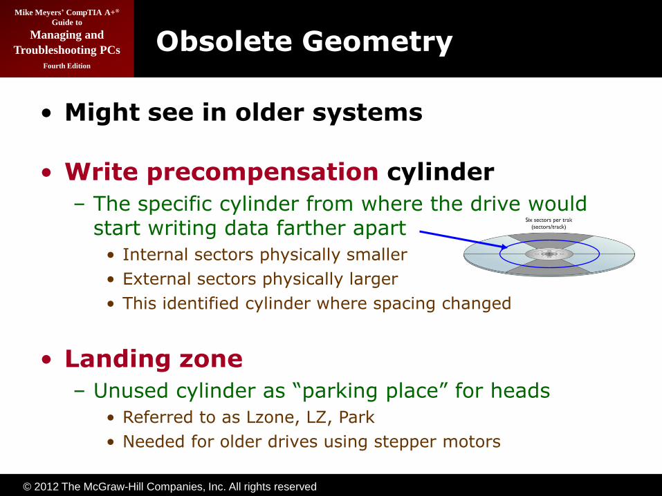
Obsolete Geometry
• Might see in older systems
• Write precompensation cylinder
– The specific cylinder from where the drive would start writing data farther apart
• Internal sectors physically smaller
• External sectors physically larger
• This identified cylinder where spacing changed
• Landing zone
– Unused cylinder as ―parking place‖ for heads
• Referred to as Lzone, LZ, Park
• Needed for older drives using stepper motors

© 2012 The McGraw-Hill Companies, Inc. All rights reserved
Mike Meyers’ CompTIA A+®
Guide to
Managing and
Troubleshooting PCs
Fourth Edition
Spindle or (rotational) speed
• Measured in revolutions per minute (RPM)
– The faster the drive, the better the performance
• Common speeds:
– 5400, 7200, 10,000, and 15,000 RPM
• Faster rotational speed produces more heat
– Airflow is a key factor in reducing heat
– Reduce heat with case fans or bay fans

© 2012 The McGraw-Hill Companies, Inc. All rights reserved
Mike Meyers’ CompTIA A+®
Guide to
Managing and
Troubleshooting PCs
Fourth Edition
Spindle or (rotational) speed (continued)
Figure 6: Bay fan
© 2012 The McGraw-Hill Companies, Inc. All rights reserved
Mike Meyers’ CompTIA A+®
Guide to
Managing and
Troubleshooting PCs
Fourth Edition
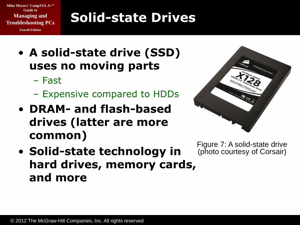
Solid-state Drives
• A solid-state drive (SSD) uses no moving parts
– Fast
– Expensive compared to HDDs
• DRAM- and flash-based drives (latter are more common)
• Solid-state technology in hard drives, memory cards, and more
Figure 7: A solid-state drive (photo courtesy of Corsair)

© 2012 The McGraw-Hill Companies, Inc. All rights reserved
Mike Meyers’ CompTIA A+®
Guide to
Managing and
Troubleshooting PCs
Fourth Edition
Flash-based SSDs
• Pure flash drives for portables
• Advantages:
– Very low-power usage and heat generation
– Very fast in reads because no moving parts
– Extremely rugged—nothing to break
• Disadvantages
– Price (as of early 2010)
• HDDs: $0.10 per GB capacity
• SSDs: $3.50 per GB capacity
– Capacity much lower than HDDs, but climbing

© 2012 The McGraw-Hill Companies, Inc. All rights reserved
Mike Meyers’ CompTIA A+®
Guide to
Managing and
Troubleshooting PCs
Fourth Edition
Parallel and Serial ATA
• ATA interfaces dominate today’s market
– Many changes throughout years
– Parallel ATA (PATA) historically prominent
– Serial ATA (SATA) since 2003
– Called integrated drive electronics (IDE)

© 2012 The McGraw-Hill Companies, Inc. All rights reserved
Mike Meyers’ CompTIA A+®
Guide to
Managing and
Troubleshooting PCs
Fourth Edition
ATA Overview
Cable Keywords Speed Max size
ATA-1 40-pin PIO and DMA 3.3 MBps to 8.3 MBps 504 MB
ATA-2 40-pin EIDE
ATAPI
11.1 MBps to 16.6 MBps 8.4 GB
ATA-3 40-pin S.M.A.R.T. 11.1 MBps to 16.6 MBps 8.4 GB
ATA-4 40-pin Ultra 16.7 MBps to 33.3 MBps 8.4 GB
INT13 BIOS
Upgrade
137 GB
ATA-5 40-pin
80-wire
ATA/33
ATA/66
44.4 MBps to 6.6 MBps 137 GB
ATA-6 40-pin
80-wire
Big Drive 100 MBps 144 PB
ATA-7 40-pin
80-wire
7-pin
ATA/133
SATA
133 MBps to 300 MBps 144 PB
© 2012 The McGraw-Hill Companies, Inc. All rights reserved
Mike Meyers’ CompTIA A+®
Guide to
Managing and
Troubleshooting PCs
Fourth Edition
ATA-1
• 40-pin ribbon cable
• Allowed two drives (one master, one slave)
• Programmable I/O (PIO)—traditional data transfer
– 3.3 MBps to 8.3 MBps
• DMA—direct memory access
– 2.1 MBps to 8.3 MBps
• Maximum capacity = 504 MB
© 2012 The McGraw-Hill Companies, Inc. All rights reserved
Mike Meyers’ CompTIA A+®
Guide to
Managing and
Troubleshooting PCs
Fourth Edition
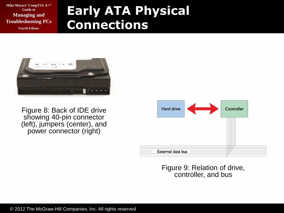
Early ATA Physical Connections
Figure 8: Back of IDE drive showing 40-pin connector
(left), jumpers (center), and power connector (right)
Figure 9: Relation of drive, controller, and bus
© 2012 The McGraw-Hill Companies, Inc. All rights reserved
Mike Meyers’ CompTIA A+®
Guide to
Managing and
Troubleshooting PCs
Fourth Edition
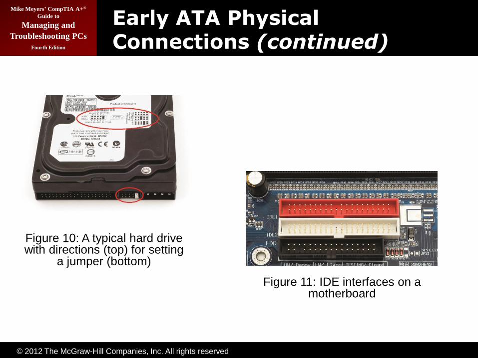
Early ATA Physical Connections (continued)
Figure 10: A typical hard drive with directions (top) for setting
a jumper (bottom)
Figure 11: IDE interfaces on a motherboard

© 2012 The McGraw-Hill Companies, Inc. All rights reserved
Mike Meyers’ CompTIA A+®
Guide to
Managing and
Troubleshooting PCs
Fourth Edition
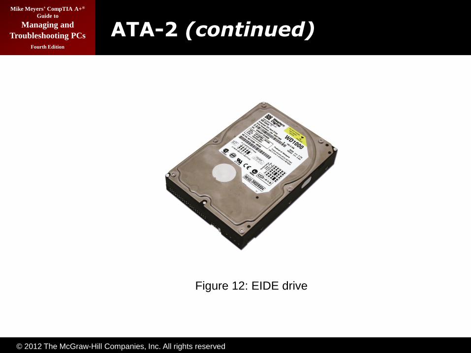
ATA-2
• Commonly called EIDE (Western Digital marketing term)
• Increased maximum size to 8.2 GB through LBA and sector translation
• Added ATAPI
– Could now use CD drives
• Added second controller
• Added new PIO and DMA modes to increase data transfers to 16.6 MBps
© 2012 The McGraw-Hill Companies, Inc. All rights reserved
Mike Meyers’ CompTIA A+®
Guide to
Managing and
Troubleshooting PCs
Fourth Edition
ATA-2 (continued)
Figure 12: EIDE drive
© 2012 The McGraw-Hill Companies, Inc. All rights reserved
Mike Meyers’ CompTIA A+®
Guide to
Managing and
Troubleshooting PCs
Fourth Edition
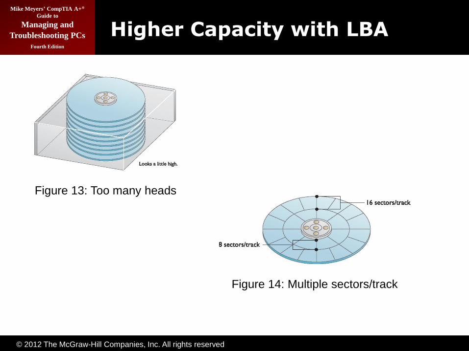
Higher Capacity with LBA
Figure 13: Too many heads
Figure 14: Multiple sectors/track
© 2012 The McGraw-Hill Companies, Inc. All rights reserved
Mike Meyers’ CompTIA A+®
Guide to
Managing and
Troubleshooting PCs
Fourth Edition
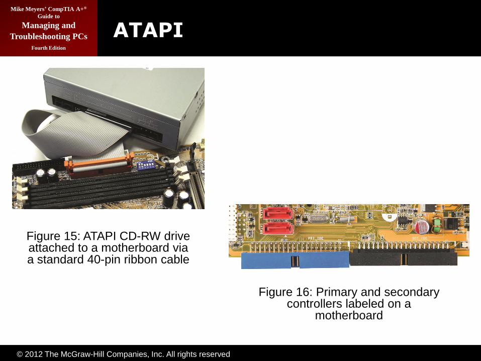
ATAPI
Figure 15: ATAPI CD-RW drive attached to a motherboard via a standard 40-pin ribbon cable
Figure 16: Primary and secondary controllers labeled on a
motherboard

© 2012 The McGraw-Hill Companies, Inc. All rights reserved
Mike Meyers’ CompTIA A+®
Guide to
Managing and
Troubleshooting PCs
Fourth Edition
ATA-3
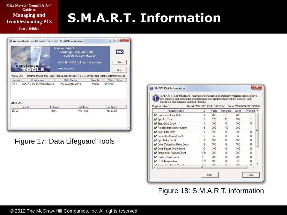
• Self-Monitoring Analysis and Reporting Technology
– S.M.A.R.T.
• No real change in other stats
© 2012 The McGraw-Hill Companies, Inc. All rights reserved
Mike Meyers’ CompTIA A+®
Guide to
Managing and
Troubleshooting PCs
Fourth Edition
S.M.A.R.T. Information
Figure 17: Data Lifeguard Tools
Figure 18: S.M.A.R.T. information

© 2012 The McGraw-Hill Companies, Inc. All rights reserved
Mike Meyers’ CompTIA A+®
Guide to
Managing and
Troubleshooting PCs
Fourth Edition
ATA-4
• Introduced Ultra DMA Modes
– Ultra DMA Mode 0: 16.7 MBps
– Ultra DMA Mode 1: 25 MBps
– Ultra DMA Mode 2: 33 MBps
– These are forms of DMA bus mastering
• Ultra DMA Mode 2 also called ATA/33

© 2012 The McGraw-Hill Companies, Inc. All rights reserved
Mike Meyers’ CompTIA A+®
Guide to
Managing and
Troubleshooting PCs
Fourth Edition
INT13 Extensions
• ATA-1 standard actually written for hard drives up to 137 GB
– BIOS limited it to 504 MB due to cylinder, head, and sector maximums
– ATA-2 implemented LBA to fool the BIOS, enabling drives up to 8.4 GB
• INT13 Extensions extended BIOS commands
– Enabled drives up to 137 GB

© 2012 The McGraw-Hill Companies, Inc. All rights reserved
Mike Meyers’ CompTIA A+®
Guide to
Managing and
Troubleshooting PCs
Fourth Edition
ATA-5
• Introduced newer Ultra DMA Modes
– Ultra DMA Mode 3: 44.4 MBps
– Ultra DMA Mode 4: 66.6 MBps
• Ultra DMA Mode 4 also called ATA/66
• Used 40-pin cable, but had 80 wires
– Blue connector—to controller
– Gray connector—slave drive
– Black connector—master drive
Figure 19: ATA/66 cable
© 2012 The McGraw-Hill Companies, Inc. All rights reserved
Mike Meyers’ CompTIA A+®
Guide to
Managing and
Troubleshooting PCs
Fourth Edition
ATA-6
• “Big Drives” introduced (name soon changed to ATA/ATAPI-6)
• Replaced INT13 & 24-bit LBA to 48-bit LBA
• Increased maximum size to 144 PB
– 144,000,000 GB
• Introduced Ultra DMA 5
– Ultra DMA Mode 5: 100 MBps (ATA/100)
– Used same 40-pin, 80-wire cables as ATA-5
© 2012 The McGraw-Hill Companies, Inc. All rights reserved
Mike Meyers’ CompTIA A+®
Guide to
Managing and
Troubleshooting PCs
Fourth Edition
ATA-7
• Introduced Ultra DMA 6
– Ultra DMA Mode 6: 133 MBps (ATA/133)
– Used same 40-pin, 80-wire cables as ATA-5
– Didn’t really take off due to SATA’s popularity
• Introduced Serial ATA (SATA)
– Increased throughput to 150 MBps to 300 MBps
© 2012 The McGraw-Hill Companies, Inc. All rights reserved
Mike Meyers’ CompTIA A+®
Guide to
Managing and
Troubleshooting PCs
Fourth Edition
End of PATA
• Ultra DMA Mode 6
– Up to 133 Mbps
– ATA/133
– 80-wire cable
• Problems with PATA
– Wide, flat cables impede airflow
– Cable limited to 18‖
– No hot-swapping
– Reached limits of technology
© 2012 The McGraw-Hill Companies, Inc. All rights reserved
Mike Meyers’ CompTIA A+®
Guide to
Managing and
Troubleshooting PCs
Fourth Edition
Serial ATA
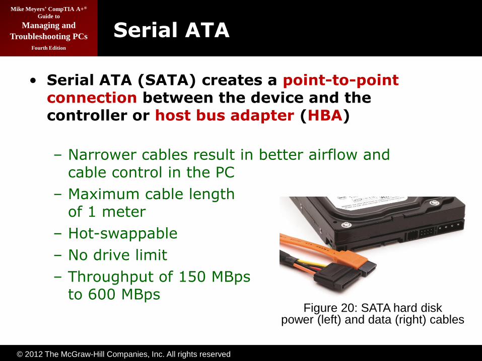
• Serial ATA (SATA) creates a point-to-point connection between the device and the controller or host bus adapter (HBA)
– Narrower cables result in better airflow and cable control in the PC
– Maximum cable length of 1 meter
– Hot-swappable
– No drive limit
– Throughput of 150 MBps to 600 MBps
Figure 20: SATA hard disk power (left) and data (right) cables

© 2012 The McGraw-Hill Companies, Inc. All rights reserved
Mike Meyers’ CompTIA A+®
Guide to
Managing and
Troubleshooting PCs
Fourth Edition
SATA Bridge
Figure 21: SATA bridge

© 2012 The McGraw-Hill Companies, Inc. All rights reserved
Mike Meyers’ CompTIA A+®
Guide to
Managing and
Troubleshooting PCs
Fourth Edition
AHCI
• Windows Vista/7 support Advanced Host Controller Interface (AHCI)
– Efficient way to work with SATA HBAs
– Makes hot-swapping work well (otherwise have to run the Add New Hardware Wizard)
– Native command queuing (NCQ) is a disk-
optimization feature that enables faster read/write speeds
– Implement AHCI in CMOS before installing the OS
© 2012 The McGraw-Hill Companies, Inc. All rights reserved
Mike Meyers’ CompTIA A+®
Guide to
Managing and
Troubleshooting PCs
Fourth Edition
SATA Naming
• SATA drives come in two flavors
– SATA 1.5Gb
– SATA 3Gb
• Marketing hype has branded SATA 3Gb drives as SATA II
• SATA committee is called the SATA-IO
• Note the numbers don’t quite add up
– 1.5 Gb = 192 MBps, not 150 MBps
– Up to 20 percent lost to overhead and encoding scheme, thus the lower actual speed

© 2012 The McGraw-Hill Companies, Inc. All rights reserved
Mike Meyers’ CompTIA A+®
Guide to
Managing and
Troubleshooting PCs
Fourth Edition
External Serial ATA
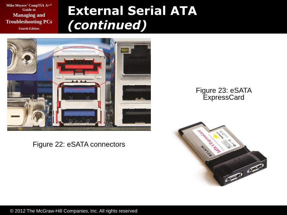
• eSATA– External SATA
– Extends SATA bus to external devices
– Cable length up to 2 meters
– eSATA extends the SATA bus at full speed, which tops out at a theoretical 6 Gbps, whereas the fastest USB connection (USB 3.0, also called SuperSpeed USB) maxes out at 5 Gbps.
© 2012 The McGraw-Hill Companies, Inc. All rights reserved
Mike Meyers’ CompTIA A+®
Guide to
Managing and
Troubleshooting PCs
Fourth Edition
External Serial ATA (continued)
Figure 22: eSATA connectors
Figure 23: eSATA ExpressCard
© 2012 The McGraw-Hill Companies, Inc. All rights reserved
Mike Meyers’ CompTIA A+®
Guide to
Managing and
Troubleshooting PCs
Fourth Edition
SCSISmall Computer System Interface

© 2012 The McGraw-Hill Companies, Inc. All rights reserved
Mike Meyers’ CompTIA A+®
Guide to
Managing and
Troubleshooting PCs
Fourth Edition
SCSI
• Pronounced “Scuzzy”
• Been around since 1970s
• Devices can be internal or external
• Historically the choice for RAID
– Faster than PATA
– Could have more than four drives
• SATA replacing SCSI in many applications

© 2012 The McGraw-Hill Companies, Inc. All rights reserved
Mike Meyers’ CompTIA A+®
Guide to
Managing and
Troubleshooting PCs
Fourth Edition
SCSI Chains
• A SCSI chain is a series of SCSI devices working together through a host adapter.
• The host adapter is a device that attaches the SCSI chain to the PC.
• All SCSI devices are divided into internal and external groups.

© 2012 The McGraw-Hill Companies, Inc. All rights reserved
Mike Meyers’ CompTIA A+®
Guide to
Managing and
Troubleshooting PCs
Fourth Edition
SCSI Chains (continued)
Figure 24: SCSI host adapter

© 2012 The McGraw-Hill Companies, Inc. All rights reserved
Mike Meyers’ CompTIA A+®
Guide to
Managing and
Troubleshooting PCs
Fourth Edition
SCSI Chains (continued)
Figure 25: Internal SCSI CD-ROM
Figure 26: Back of external SCSI device

© 2012 The McGraw-Hill Companies, Inc. All rights reserved
Mike Meyers’ CompTIA A+®
Guide to
Managing and
Troubleshooting PCs
Fourth Edition
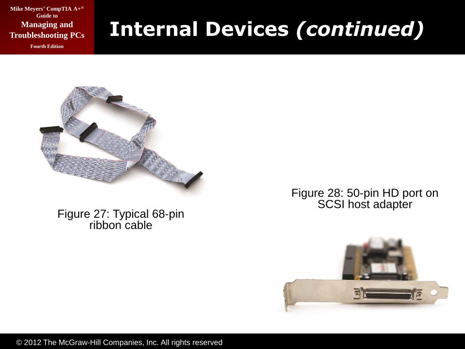
Internal Devices
• Internal SCSI devices are installed inside the PC and connect to the host adapter through the internal connector.
• Internal devices use a 68-pin ribbon cable.
• Cables can be connected to multiple devices.
© 2012 The McGraw-Hill Companies, Inc. All rights reserved
Mike Meyers’ CompTIA A+®
Guide to
Managing and
Troubleshooting PCs
Fourth Edition
Internal Devices (continued)
Figure 27: Typical 68-pin ribbon cable
Figure 28: 50-pin HD port on SCSI host adapter
© 2012 The McGraw-Hill Companies, Inc. All rights reserved
Mike Meyers’ CompTIA A+®
Guide to
Managing and
Troubleshooting PCs
Fourth Edition
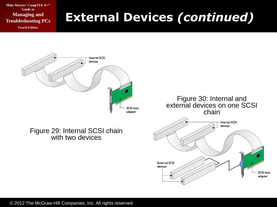
External Devices
• External SCSI devices are connected to external connection of host adapter.
• External devices may have two connections in the back to allow for daisy-chaining.
• A standard SCSI chain can connect 15 devices, plus the host adapter.
© 2012 The McGraw-Hill Companies, Inc. All rights reserved
Mike Meyers’ CompTIA A+®
Guide to
Managing and
Troubleshooting PCs
Fourth Edition
External Devices (continued)
Figure 29: Internal SCSI chain with two devices
Figure 30: Internal and external devices on one SCSI
chain
© 2012 The McGraw-Hill Companies, Inc. All rights reserved
Mike Meyers’ CompTIA A+®
Guide to
Managing and
Troubleshooting PCs
Fourth Edition
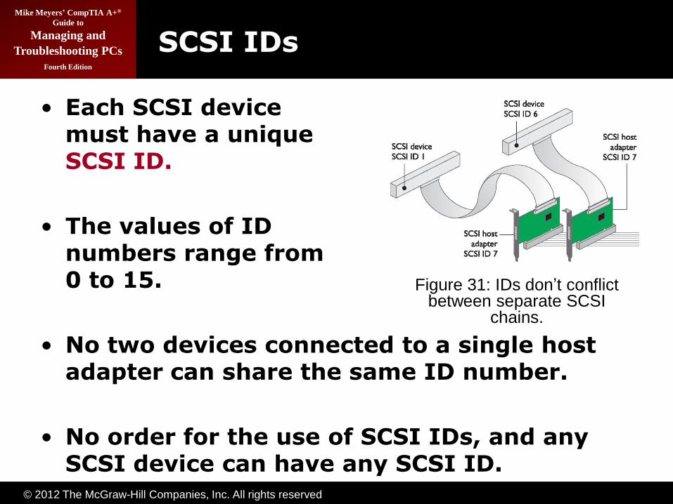
SCSI IDs
• Each SCSI device must have a unique SCSI ID.
• The values of ID numbers range from 0 to 15.
• No two devices connected to a single host adapter can share the same ID number.
• No order for the use of SCSI IDs, and any SCSI device can have any SCSI ID.
Figure 31: IDs don’t conflict between separate SCSI
chains.
© 2012 The McGraw-Hill Companies, Inc. All rights reserved
Mike Meyers’ CompTIA A+®
Guide to
Managing and
Troubleshooting PCs
Fourth Edition
SCSI IDs (continued)
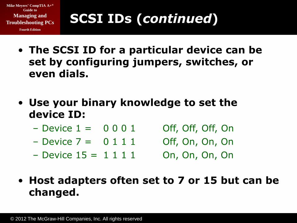
• The SCSI ID for a particular device can be set by configuring jumpers, switches, or even dials.
• Use your binary knowledge to set the device ID:
– Device 1 = 0 0 0 1 Off, Off, Off, On
– Device 7 = 0 1 1 1 Off, On, On, On
– Device 15 = 1 1 1 1 On, On, On, On
• Host adapters often set to 7 or 15 but can be changed.

© 2012 The McGraw-Hill Companies, Inc. All rights reserved
Mike Meyers’ CompTIA A+®
Guide to
Managing and
Troubleshooting PCs
Fourth Edition
Termination
• Terminators are used to prevent a signal reflection that can corrupt the signal.
• Pull-down resistors are usually used as terminators.
• Only the ends of the SCSI chains should be terminated.
• Most manufacturers build SCSI devices that self-terminate.
Figure 32: Location of the terminated devices

© 2012 The McGraw-Hill Companies, Inc. All rights reserved
Mike Meyers’ CompTIA A+®
Guide to
Managing and
Troubleshooting PCs
Fourth Edition
Termination (continued)
Figure 32: Location of the terminated devices
Figure 33: Setting termination

© 2012 The McGraw-Hill Companies, Inc. All rights reserved
Mike Meyers’ CompTIA A+®
Guide to
Managing and
Troubleshooting PCs
Fourth Edition
Protecting Data with RAID
© 2012 The McGraw-Hill Companies, Inc. All rights reserved
Mike Meyers’ CompTIA A+®
Guide to
Managing and
Troubleshooting PCs
Fourth Edition
• The most important part of a PC is the data it holds.
– Companies have gone out of business because of losing data on hard drives.
• Hard drives will eventually develop faults.
• Fault tolerance enables systems to operate even when a component fails.
– Redundant array of inexpensive disks (RAID) is one such technology.
Protecting Data

© 2012 The McGraw-Hill Companies, Inc. All rights reserved
Mike Meyers’ CompTIA A+®
Guide to
Managing and
Troubleshooting PCs
Fourth Edition
Protecting Data (continued)
Figure 34:Mirrored drivesFigure 35: Duplexing drives
Figure 36: Disk striping

© 2012 The McGraw-Hill Companies, Inc. All rights reserved
Mike Meyers’ CompTIA A+®
Guide to
Managing and
Troubleshooting PCs
Fourth Edition
RAID Level 0
• Disk striping
– Writes data across multiple drives at once
– Requires at least two hard drives
– Provides increased read and writes
• Not fault tolerant
– If any drive fails, the data is lost
© 2012 The McGraw-Hill Companies, Inc. All rights reserved
Mike Meyers’ CompTIA A+®
Guide to
Managing and
Troubleshooting PCs
Fourth Edition
RAID Level 1
• Disk mirroring/duplexing is the process of writing the same data to two drives at the same time
– Requires two drives
– Produces an exact mirror of the primary drive
– Mirroring uses the same controller
– Duplexing uses separate controllers
© 2012 The McGraw-Hill Companies, Inc. All rights reserved
Mike Meyers’ CompTIA A+®
Guide to
Managing and
Troubleshooting PCs
Fourth Edition
RAID Levels 2 to 4
• RAID 2
– Disk striping with multiple parity drives
– Not used
• RAID 3 and 4
– Disk striping with dedicated parity
– Dedicated data drives and dedicated parity drives
– Quickly replaced by RAID 5

© 2012 The McGraw-Hill Companies, Inc. All rights reserved
Mike Meyers’ CompTIA A+®
Guide to
Managing and
Troubleshooting PCs
Fourth Edition
RAID Level 5
• Disk striping with distributed parity
– Distributes data and parity evenly across the drives
– Requires at least three drives
– Most common RAID implementation

© 2012 The McGraw-Hill Companies, Inc. All rights reserved
Mike Meyers’ CompTIA A+®
Guide to
Managing and
Troubleshooting PCs
Fourth Edition
RAID Level 6
• Super disk striping with distributed parity
– RAID 5 with asynchronous and cached data capability
– Requires at least five drives, but can lose up to two drives and still recover

© 2012 The McGraw-Hill Companies, Inc. All rights reserved
Mike Meyers’ CompTIA A+®
Guide to
Managing and
Troubleshooting PCs
Fourth Edition
RAID Oddities and JBOD
• Consumer-oriented boards offer “special” features
• RAID 0+1
– Two striped sets mirrored
• RAID 1+0 (RAID “10”)
– Two mirrored sets striped
– Both require four drives
• Just a Bunch of Disks (JBOD)

© 2012 The McGraw-Hill Companies, Inc. All rights reserved
Mike Meyers’ CompTIA A+®
Guide to
Managing and
Troubleshooting PCs
Fourth Edition
Implementing RAID
• SCSI has been the primary choice in the past
– Faster than PATA
– Hot-swappable
– PATA supported only four drives
• SATA today viewed as comparable choice
– Speeds comparable to SCSI
– Less expensive than SCSI
– Hot-swappable
– Dedicated SATA controllers can support up to 15 drives

© 2012 The McGraw-Hill Companies, Inc. All rights reserved
Mike Meyers’ CompTIA A+®
Guide to
Managing and
Troubleshooting PCs
Fourth Edition
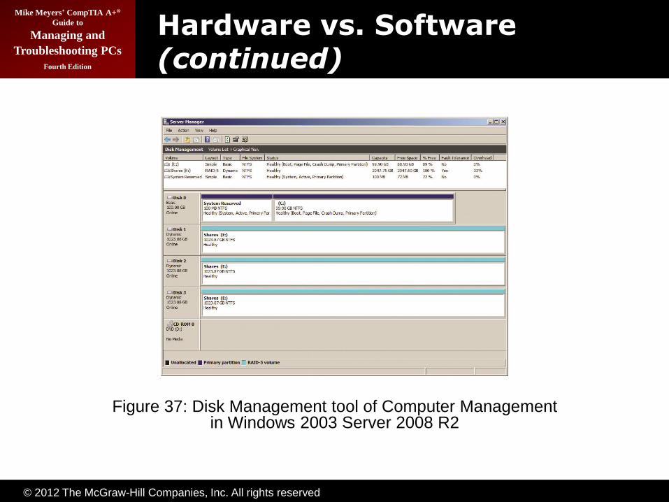
Hardware vs. Software
• Hardware RAID
– Dedicated controller
– Operating system views it as single volume
• Software RAID
– Operating system recognizes all individual disks
– Combines them together as single volume
© 2012 The McGraw-Hill Companies, Inc. All rights reserved
Mike Meyers’ CompTIA A+®
Guide to
Managing and
Troubleshooting PCs
Fourth Edition
Hardware vs. Software (continued)
Figure 37: Disk Management tool of Computer Management in Windows 2003 Server 2008 R2

© 2012 The McGraw-Hill Companies, Inc. All rights reserved
Mike Meyers’ CompTIA A+®
Guide to
Managing and
Troubleshooting PCs
Fourth Edition
Hardware vs. Software (continued)
Figure 38: Serial ATA RAID controller
Figure 39: RAID configuration utility

© 2012 The McGraw-Hill Companies, Inc. All rights reserved
Mike Meyers’ CompTIA A+®
Guide to
Managing and
Troubleshooting PCs
Fourth Edition
Personal RAID
• ATA RAID controller chips have gone down in price.
• Many motherboards are now shipping with RAID built-in.
• The future is RAID.
– RAID has been around for 20 years, but is now less expensive and moving into desktop systems.

© 2012 The McGraw-Hill Companies, Inc. All rights reserved
Mike Meyers’ CompTIA A+®
Guide to
Managing and
Troubleshooting PCs
Fourth Edition
Installing Drives
© 2012 The McGraw-Hill Companies, Inc. All rights reserved
Mike Meyers’ CompTIA A+®
Guide to
Managing and
Troubleshooting PCs
Fourth Edition
Connecting Your Drive
• Choosing your drive
– PATA, SATA, or SCSI
– Check BIOS and motherboard for support
• Jumpers and cabling on PATA
– Master
– Slave
– Cable select
© 2012 The McGraw-Hill Companies, Inc. All rights reserved
Mike Meyers’ CompTIA A+®
Guide to
Managing and
Troubleshooting PCs
Fourth Edition
Connecting Your Drive (continued)
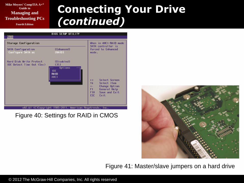
Figure 40: Settings for RAID in CMOS
Figure 41: Master/slave jumpers on a hard drive

© 2012 The McGraw-Hill Companies, Inc. All rights reserved
Mike Meyers’ CompTIA A+®
Guide to
Managing and
Troubleshooting PCs
Fourth Edition
Connecting Your Drive (continued)
Figure 42: Drive label showing master/slave settings
© 2012 The McGraw-Hill Companies, Inc. All rights reserved
Mike Meyers’ CompTIA A+®
Guide to
Managing and
Troubleshooting PCs
Fourth Edition
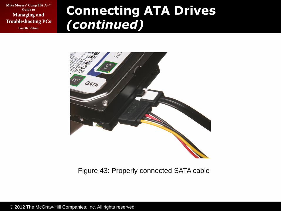
Connecting ATA Drives
• PATA
– Ribbon cable pin 1 to pin 1
– Molex for power
• SATA
– Cable keyed, so goes in one way
– SATA for power, though some can use Molex
• SATA best practice
– Install drive you want as primary/bootable into first SATA controller, usually SATA 0
© 2012 The McGraw-Hill Companies, Inc. All rights reserved
Mike Meyers’ CompTIA A+®
Guide to
Managing and
Troubleshooting PCs
Fourth Edition
Connecting ATA Drives (continued)
Figure 43: Properly connected SATA cable
© 2012 The McGraw-Hill Companies, Inc. All rights reserved
Mike Meyers’ CompTIA A+®
Guide to
Managing and
Troubleshooting PCs
Fourth Edition
Connecting SSDs
• Most likely to find in portable PCs
• Connect the same way HDDs connect
– PATA
– SATA
• Drivers needed for pre-Vista Windows

© 2012 The McGraw-Hill Companies, Inc. All rights reserved
Mike Meyers’ CompTIA A+®
Guide to
Managing and
Troubleshooting PCs
Fourth Edition
Connecting SCSI Drives
• First need compatible controller
– Different types of SCSI
• Connect data cable
– Reversing this cable can damage drive, data, or both
– Pin 1 to pin 1, just like PATA
• Connect power—Molex connector
• Configure SCSI IDs on drives and controller
© 2012 The McGraw-Hill Companies, Inc. All rights reserved
Mike Meyers’ CompTIA A+®
Guide to
Managing and
Troubleshooting PCs
Fourth Edition
BIOS Support: Configuring CMOS and Installing Drivers
© 2012 The McGraw-Hill Companies, Inc. All rights reserved
Mike Meyers’ CompTIA A+®
Guide to
Managing and
Troubleshooting PCs
Fourth Edition
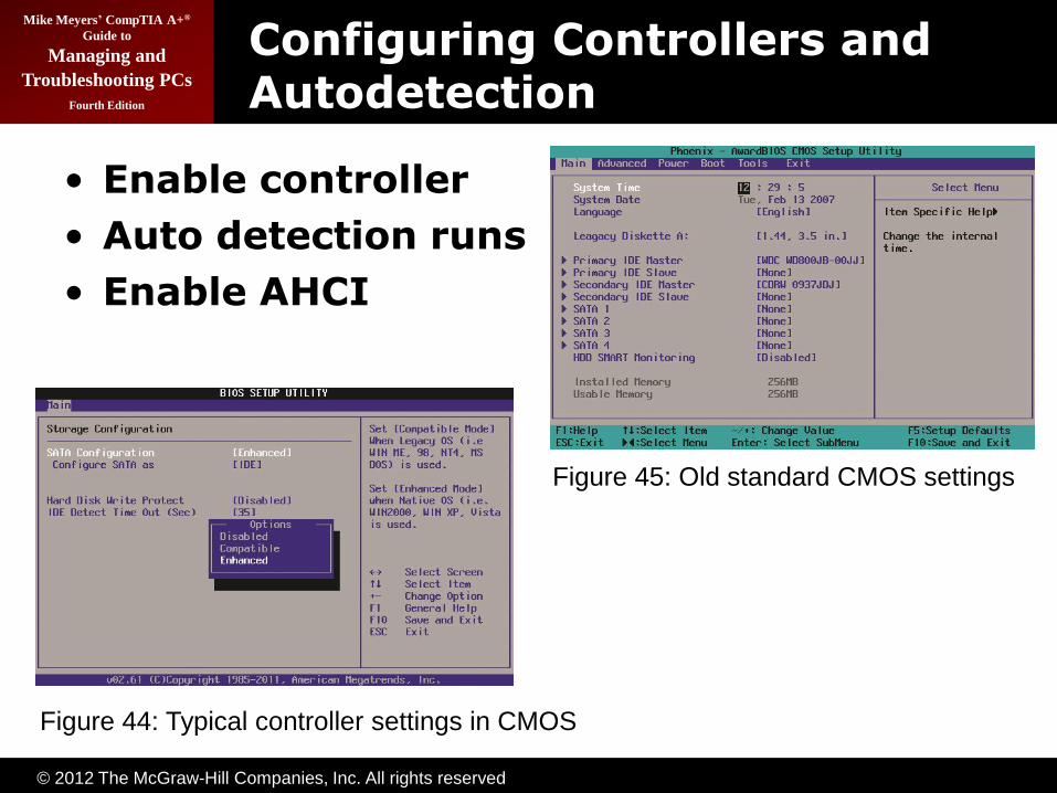
Configuring Controllers and Autodetection
• Enable controller
• Auto detection runs
• Enable AHCI
Figure 44: Typical controller settings in CMOS
Figure 45: Old standard CMOS settings
© 2012 The McGraw-Hill Companies, Inc. All rights reserved
Mike Meyers’ CompTIA A+®
Guide to
Managing and
Troubleshooting PCs
Fourth Edition
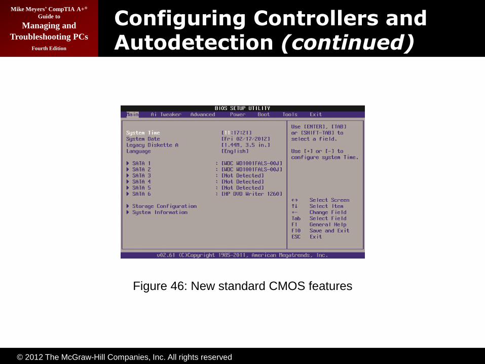
Configuring Controllers and Autodetection (continued)
Figure 46: New standard CMOS features

© 2012 The McGraw-Hill Companies, Inc. All rights reserved
Mike Meyers’ CompTIA A+®
Guide to
Managing and
Troubleshooting PCs
Fourth Edition
Boot Order
• Identifies where computer will try to load an operating system
– Multiple devices configured
– First one with an OS will boot
Figure 47: Boot order

© 2012 The McGraw-Hill Companies, Inc. All rights reserved
Mike Meyers’ CompTIA A+®
Guide to
Managing and
Troubleshooting PCs
Fourth Edition
Troubleshooting Hard Drive
Installation
• Autodetect fails
– Power
– Ribbon cable installed improperly
– Jumpers set incorrectly
• Simplify and try again, one drive at a time
• Physical settings correct? Try CMOS
errors
– Controller disabled
– ATA level supported? (i.e., is the drive too large for
your BIOS to see properly?)
– Check the manufacturer's Web site for known issues

© 2012 The McGraw-Hill Companies, Inc. All rights reserved
Mike Meyers’ CompTIA A+®
Guide to
Managing and
Troubleshooting PCs
Fourth Edition
Beyond A+
• Hybrid Hard Drives (HHD)
– Combine flash memory and traditional platters
– Up to 256-MB flash for fast cache for data and boot
• Essential OS boot files on flash
– Platters do not spin by default
• Lower power usage
– Read/write to flash unless need data from HDD or
buffer exceeded
– Could shave boot times in half and add battery life
– Only Windows Vista and Windows 7


![BackTrack Hard Drive Installation Hard Drive... · · 2016-07-07BackTrack Hard Drive Installation BackTrack Development Team jabra [at] remote-exploit ... Mount the Devices](https://img.pdfslide.net/doc/110x75/5ae57f027f8b9a6d4f8b5d64/backtrack-hard-drive-installation-hard-drive2016-07-07backtrack-hard-drive-installation.jpg)