Embed Size (px)
Citation preview

This journal is©The Royal Society of Chemistry 2019 Soft Matter, 2019, 15, 8543--8551 | 8543
Cite this: SoftMatter, 2019,
15, 8543
Hard topological versus soft geometricalmagnetic particle transport†
Anna M. E. B. Rossi,a Jonas Bugase,ab Thomas Lachner, a Adrian Ernst,a
Daniel de las Heras c and Thomas M. Fischer *a
The question of how a dissipative geometrical transport system changes towards a topological transport
system is important to render a fragile transport into a robust transport. We show how a macroscopic
magnetic topological transport of solid state spheres changes to a geometrical transport of ferrofluid
droplets, when instead of a solid state object, soft matter is transported. The key difference when
comparing solid objects with fluid droplets is the possibility to split a ferrofluid droplet into two droplets.
It is shown how this fundamental difference also fundamentally changes the transport properties.
Hence, experimentally and theoretically the transport on top of a periodic two-dimensional hexagonal
magnetic pattern of (i) a single macroscopic steel sphere, (ii) a doublet of wax/magnetite com-
posite spheres, and (iii) an immiscible mixture of ferrofluid droplets with a perfluorinated liquid is
analyzed. The transport of all these magnetic objects is achieved by moving an external permanent
magnet on a closed modulation loop around the two-dimensional magnetic pattern. The transport
of one and also that of two objects per unit cell is topologically protected and characterized by
discrete displacements of the particles as we continuously scan through a family of modulation loops.
The direction and the type of transport are characterized by the winding numbers of the modulation
loops around special objects in control space, which is the space for the possible directions of the
external magnetic field. The winding numbers necessary for characterizing the topological transport
increase with the number of particles per unit cell. The topological character of the transport is
destroyed, when transporting a large collection of particles per unit cell, like it is in the case of a
macroscopic assembly of magnetic nanoparticles in a ferrofluid droplet for which the transport is
geometrical and no longer topological. To characterize the change in the transport from topological
to geometrical, we perform computer simulations of the transport of an increasing number of
particles per unit cell.
1 Introduction
When a system is driven adiabatically, its state changes slowerthan any relaxation time. The state of a classical system thenfollows the same path independently of the speed of driving.If driven adiabatically at different speeds, the state of a quantumsystem also follows the same path up to the global dynamicphase1 of its wave function that cannot be measured. Measurablequantities are geometrical in the adiabatic limit, since they can bededuced from the path without the knowledge of a particular timetable with which one drives the system along this path. For a
periodically driven system, the transport of particles over aperiod then is proportional to the geometric quantity of theloop of the driving field.2–4 For example, autonomous lowReynolds number swimmers propel by a distance proportionalto the area of the driving control loop in shape space.5,6
Adiabatic quantum two-band electrons propel by an amountproportional to the area enclosed by the SU(2), respectivelySO(3) D SU(2)/Z2 matrices of the periodic control loop inducedby the external field.1,7
The area of a loop is a geometric quantity that continuouslychanges when the driving control loop is altered. When sym-metries or other conditions constraint the driving loop, thegeometrical properties might become discrete global properties,called topological invariants. Then, the transport no longerchanges continuously with the loop since families of loopsshare the same topological invariant. The transport changesdiscretely between two families of loops with different values ofthe topological invariant.7 The transport is robust because it is
a Experimentalphysik X, Physikalisches Institut, Universitat Bayreuth,
D-95440 Bayreuth, Germany. E-mail: [email protected] University for Development Studies, Department of Applied Physics, Tamale,
Ghanac Theoretische Physik II, Physikalisches Institut, Universitat Bayreuth,
D-95440 Bayreuth, Germany
† Electronic supplementary information (ESI) available. See DOI: 10.1039/c9sm01401b
Received 10th July 2019,Accepted 4th October 2019
DOI: 10.1039/c9sm01401b
rsc.li/soft-matter-journal
Soft Matter
PAPER
Publ
ishe
d on
04
Oct
ober
201
9. D
ownl
oade
d by
UN
IVE
RSI
TA
T B
AY
RE
UT
H o
n 1/
7/20
20 2
:15:
28 P
M.
View Article OnlineView Journal | View Issue
8544 | Soft Matter, 2019, 15, 8543--8551 This journal is©The Royal Society of Chemistry 2019
topologically protected. For example, in a nucleus one nucleonmust rotate by multiples of 2p when it propels by one latticeconstant above the lattice of the crystallized nucleons that formthe rest of the nucleus.8
Understanding how a system changes from geometricaltowards topological is important. With this knowledge we canchange a fragile, geometric transport into a robust topologicaltransport. For example, in the quantum Hall effect stepsbetween the plateaus in the conductivity can be created eitherby lowering the temperature or by using clean systems withfewer impurities.9 Both methods decrease the probability ofexciting unoccupied bulk Landau levels and thus make thesystem topological. For many quantum and classical systems,10–15
the transition from geometric towards topological transport canbe understood via the amount of dissipation occurring due to thescattering between states. It has, however, been shown that thereexist non-Hermitian quantum and dissipative classical topologicaltransport systems,16–20 where it is precisely the dissipation thatcauses the topological character of the transport. For thesesystems the transition from topological towards geometrical mustbe different.
The purpose of this work is to show how topological transportphenomena also play a role in soft matter systems. We showexperimentally and with computer simulations that a macro-scopic topological magnetic particle pump,21 which transportsparamagnetic or soft magnetic particles across a magnetic lattice,is topological when transporting a small number of particles perunit cell. The transport is robust for the modulation loops ofa driving homogeneous external field that share the sametopological invariant. Subclasses of modulation loops appearfor a loading with two or more particles per unit cell, increasing
the number of discrete steps. However, for loadings with amacroscopic ensemble of magnetic nanoparticles, such as aferrofluid droplet, the topological nature of the transport isdestroyed and becomes geometrical.
2 Topogeometrical pump
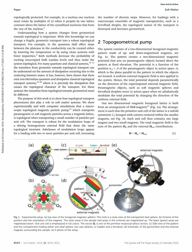
The system consists of a two-dimensional hexagonal magneticpattern made of up- and down-magnetized magnets, seeFig. 1a. The pattern creates a two-dimensional magneticpotential that acts on paramagnetic objects located above thepattern at fixed elevation. The potential is a function of theposition xA 2 A of the paramagnetic object in action space A,which is the plane parallel to the pattern in which the objectsare located. A uniform external magnetic field is also applied tothe system. Hence, the total potential depends parametricallyon the direction of the superimposed external magnetic field.Paramagnetic objects, such as soft magnetic spheres andferrofluid droplets move in action space when we adiabaticallymodulate the total potential by changing the direction of theuniform external field.
Our two dimensional magnetic hexagonal lattice is builtfrom an arrangement of NbB-magnets21 (Fig. 1a). The arrange-ment is such that the primitive unit cell of the lattice is a sixfoldsymmetric C6 hexagon with corners centered within the smallermagnets, see Fig. 1b. Each unit cell thus contains one largemagnet and two small magnets. The total magnetic field is thesum of the pattern Hp and the external Hext contributions
H = Hp + Hext. (1)
Fig. 1 Experimental setup: (a) top view of the hexagonal magnetic pattern. The inset is a close view of the transported steel sphere. (b) Scheme of theposition and the orientation of the magnets. The silver areas in the sample (red areas in the scheme) are magnetized up. The black (green) areas aremagnetized down. One unit cell is emphasized in full colors. The vector Q1 is one of the primitive reciprocal lattice vectors. (c) Side view of the patternand the compartment holding either one steel sphere, two wax spheres, or Galden and a ferrofluid. (d) Schematic of the goniometer and the externalmagnets surrounding the sample. (e) A photo of the setup.
Paper Soft Matter
Publ
ishe
d on
04
Oct
ober
201
9. D
ownl
oade
d by
UN
IVE
RSI
TA
T B
AY
RE
UT
H o
n 1/
7/20
20 2
:15:
28 P
M.
View Article Online
This journal is©The Royal Society of Chemistry 2019 Soft Matter, 2019, 15, 8543--8551 | 8545
The potential energy of a paramagnetic object in the total magneticfield H is proportional to the square of the magnetic field
U xAð Þ / �H2; (2)
and it can be decomposed into a discrete Fourier series ofcontributions from reciprocal lattice vectors.17,23 The Fourier seriesof the potential evaluated in a plane above the pattern and parallelto it is the square of the Fourier series of the magnetization of thepattern augmented by the external field. As a function of elevation,the higher Fourier coefficients are attenuated more than thosewith lower reciprocal vectors. At the experimental elevation (com-parable to the length of the unit cell of the pattern), only the‘‘universal’’ contributions to the potential from the lowest non-zeroreciprocal lattice vectors remain relevant.17,23 The purpose of thespacer (Fig. 1c) is thus to render the potential universal such thatonly the symmetry and not the fine details of the pattern areimportant.
We either place one steel sphere or two spheres consisting of amixture of wax and magnetite on top of the spacer. Alternatively,we fill a closed compartment with a mixture of a nonmagneticfluid (Galden) and an aqueous ferrofluid, immiscible with theGalden. The choice of particles and ferrofluids to be transportedis made in a way as to suppress dipolar interactions and fingeringinstabilities24,25 that are known to govern the behavior of ferro-fluids at stronger magnetic fields. The magnetic pattern with thetransported paramagnetic object on top is then placed in thecenter of a goniometer. Both, a sketch and an actual picture ofthe setup are shown in Fig. 1d and e, respectively. The gonio-meter holds two large NbB-magnets that generate the externalfield. The magnets are aligned parallel to each other and createan external magnetic field of magnitude m0Hext = 45 mT thatpenetrates the two-dimensional pattern, the steel sphere, thewax/magnetite spheres, and the ferrofluid droplets. The dipolarinteractions between two wax/magnetite spheres or betweenferrofluid nanoparticles are weak compared to the interactionwith the pattern and the external field.
The gradient of the magnitude of the external field at theposition of the transported objects rHext E Mexttextdext
2/R4 is atleast two orders of magnitude smaller than that of the magneticfield of the pattern rHp E (Ml + Ms)/a. Hence, the field createdby the external magnets is effectively uniform. The two externalmagnets can be oriented to produce an arbitrary direction ofthe external magnetic field with respect to the pattern. A laserpointing along Hext is mounted on the goniometer, see Fig. 1e,to create a stereographic projection of the instantaneous externalmagnetic field direction on the recording plane.
3 Topologically nontrivial transportloops
The parametric dependence of the potential acting on a para-magnetic object (eqn (2)) was studied in detail in ref. 17. Thepotential has a hexagonal symmetry and the number of minimaper unit cell of the potential can be one or two, depending onthe orientation of the uniform external field. The set of possible
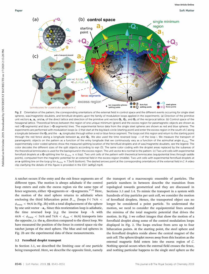
orientations of the external field forms a sphere that we call thecontrol space C (see Fig. 2b). Two minima exist in the excessregion of C (see Fig. 2b) in which the orientation of the externalfield is roughly antiparallel to the magnetization Ml of the silvermagnets in Fig. 2a. Only one minimum of the potential existsfor the orientations of the external field roughly parallel to themagnetization of silver magnets (see the green region of thecontrol space in Fig. 2b). The boundary in C between the excessregion and the region of one single minimum is a closed curve inC that we call the fence F . The fence consists of twelve segments(red and blue in Fig. 2b) meeting in twelve bifurcation points.These bifurcation points (Bþai ; and BþQi ) are located in thesouthern hemisphere of C on longitudes running through thedirections �ai and �Qi (i = 1, 2, 3) of the primitive unit vectorsof the direct and reciprocal lattice, respectively (see Fig. 2aand b). The fence segments are of two types +Q-segments(red segments in Fig. 2b) and �Q-segments (blue segments inFig. 2b).
We reorient the external magnets by moving along a closedreorientation loop that starts and ends at the same orientation.(See the black point in Fig. 2b marked as the starting pointbetween Q2 and the a3 longitude in the southern uniqueminimum region.) As a result of the reorientation loop of theexternal field, the steel sphere, the wax/magnetite spheres, andthe ferrofluid droplets move above the magnetic lattice. A motionof the steel sphere is topologically trivial when the sphereresponds to a closed reorientation loop with a closed loop onthe lattice. Not every closed reorientation loop causes such a trivialresponse of the steel sphere. There are topologically nontrivialtrajectories, where the steel sphere ends at a position differingfrom the initial position by one unit vector of the magnetic lattice.Nontrivial closed reorientation loops in control space are thoseloops that have loop segments in both the excess region and theregion of the unique minimum.17,21 Here, the reorientation loopenters the excess region with a longitude fentry between the Q2
and the �a2 directions and exits the excess region between the Q2
and the a3 longitudes at fexit = 4.4p/6. The schematic reorientationloops in control space are depicted in Fig. 2b.
3.1 Single steel sphere transport
We have reported in ref. 17, 21 and 22 how the transport of asingle paramagnetic particle changes as we move the entrylongitude 4.4p/6 o fentry o 8.5p/6 of the reorientation closedloop. Here we briefly repeat the findings which are importantfor this work. The steel sphere adiabatically returns to its initialposition (performs a closed loop above the lattice) if thereorientation loop enters and exits the excess region via thesame fence segment. As an example of such a loop we havedrawn the loop a in Fig. 2b for which fentry = fexit = 4.4p/6. Thesphere also returns to the same position when the reorientationloop encloses only the bifurcation point Ba3 or the two bifurca-tion points Ba3 and B�Q1
in C such as in the case of loops b–e(5p/6 o fentry o 7p/6 and fexit = 4.4p/6) in Fig. 2b. However, asthe modulation loop encloses Ba3 the motion is no longeradiabatic. Instead, an irreversible ratchet jump occurs as themodulation loop exits the excess region through the fence.
Soft Matter Paper
Publ
ishe
d on
04
Oct
ober
201
9. D
ownl
oade
d by
UN
IVE
RSI
TA
T B
AY
RE
UT
H o
n 1/
7/20
20 2
:15:
28 P
M.
View Article Online
8546 | Soft Matter, 2019, 15, 8543--8551 This journal is©The Royal Society of Chemistry 2019
A ratchet occurs if the entry and the exit fence segments are ofdifferent types. The motion is always adiabatic if the controlloop enters and exits the excess region via the same type offence segments, either +Q-segments or �Q-segments.17,21 Here,the motion of the steel sphere returns to adiabatic whenenclosing the third bifurcation point B�a1 (loops f–i 7p/6 ofentry o 9p/6 in Fig. 2b) with a total displacement of the sphereby one unit vector �a2. Since this reorientation loop is adiabatic,the time reversed loop (e.g. the inverse loop �h with4p/6 o fentry o 5p/6 and 7p/6 o fexit o 8p/6) transports intothe opposite, i.e. the a2 direction compared to the direct loop. Wehave measured the position of the fence in control space via theratchet jumps of the steel sphere. The blue and red spheres inFig. 2b are the experimental data of these measurements.
3.2 Ferrofluid droplet transport
In Section 3.1, we described the limiting case of one particlebeing transported. Here, we describe the opposite limit, namely
the transport of a macroscopic ensemble of particles. Theparticle numbers in between describe the transition fromtopological towards geometrical and they are discussed inSections 3.3 and 3.4. To mimic the transport in a system withhundreds of tiny particles per unit cell, we consider the motionof ferrofluid droplets. Hence, the transported object can nolonger be considered a point particle. To understand themotion, we need to consider the equipotential lines aroundthe minima of the total magnetic potential that drives themotion. In Fig. 3 we collect images that show the motion of aferrofluid droplet along some of the control modulation loopsdisplayed in Fig. 2. The loops enclose from zero up to fourbifurcation points. At the starting point, the steel sphere andthe ferrofluid droplets reside above the central magnet of theunit cell. The sphere/droplet moves away from this location as theexternal magnetic field enters into the excess region of C.Nothing special occurs when the external field crosses the fence,and nothing particular happens to the single steel sphere as the
Fig. 2 Orientation of the pattern, the corresponding orientations of the external field in control space and the different events occurring for single steelspheres, wax/magnetite-doublets, and ferrofluid droplets upon the family of modulation loops applied in the experiments. (a) Direction of the primitiveunit vectors a1, a2, and a3 of the direct lattice and direction of the primitive unit vectors Q1, Q2, and Q3 of the reciprocal lattice. (b) Control space of thehexagonal lattice. Theoretical fences between the region of one unique minimum (green) and the excess region for paramagnetic objects are shown asred (+Q segments) and blue (�Q segments) lines. The experimental fence data from the single steel spheres are shown as red and blue spheres. Theexperiments are performed with modulation loops (a–i) that start at the big black circle (starting point) and enter the excess region in the south of C alonga longitude between the Q2 and the �a2 longitudes through either a red or blue fence segment. The loops exit this region and return to the starting pointthrough the red fence along a longitude between a3 and Q2. We also used the time reversed loop �i of the loop i. We measure the transport ofparamagnetic objects on the pattern as a function of the entry longitude that we continuously vary as a function of the azimuthal angle fentry. Theexperimentally color coded spheres show the measured splitting location of the ferrofluid droplets and of wax/magnetite doublets, see the legend. Thecolor decodes the different sizes of the split objects according to eqn (3). The same color coding with the droplet areas replaced by the subareas ofthe theoretical lemniscates is used for the background in the excess region. The unit vector n is normal to the pattern. (c) Two unit cells with experimentalferrofluid droplets at a Q-splitting line for fentry E p (top). Two unit cells of the pattern with theoretical lemniscates (equipotential lines through saddlepoints), computed from the magnetic potential for an external field in the excess region (middle). Two unit cells with experimental ferrofluid droplets atan a-splitting line on the loop g for fentry E 7.5p/6 (bottom). The dashed arrows point at the corresponding orientations of the external field in C. A videoclip clarifying the details of this figure is provided in the ESI† (adfig2.mp4).
Paper Soft Matter
Publ
ishe
d on
04
Oct
ober
201
9. D
ownl
oade
d by
UN
IVE
RSI
TA
T B
AY
RE
UT
H o
n 1/
7/20
20 2
:15:
28 P
M.
View Article Online
This journal is©The Royal Society of Chemistry 2019 Soft Matter, 2019, 15, 8543--8551 | 8547
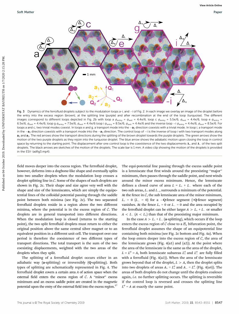
field moves deeper into the excess region. The ferrofluid droplet,however, deforms into a dogbone-like shape and eventually splitsinto two smaller droplets when the modulation loop crosses adroplet splitting line in C. Some of the shapes of such droplets areshown in Fig. 2c. Their shape and size agree very well with theshape and size of the lemniscates, which are simply the equipo-tential lines of the colloidal potential passing through the saddlepoint between both minima (see Fig. 2c). The two separatedferrofluid droplets reside in a region above the two differentminima, where the potential is in the excess region of C. Thedroplets are in general transported into different directions.When the modulation loop is closed (returns to the startingpoint), the two split ferrofluid droplets must return to either theoriginal position above the same central silver magnet or to anequivalent position in a different unit cell. The transport over oneperiod is therefore the coexistence of two different types oftransport directions. The total transport is the sum of the twocoexisting displacements, weighted with the two areas of thedroplets when they split.
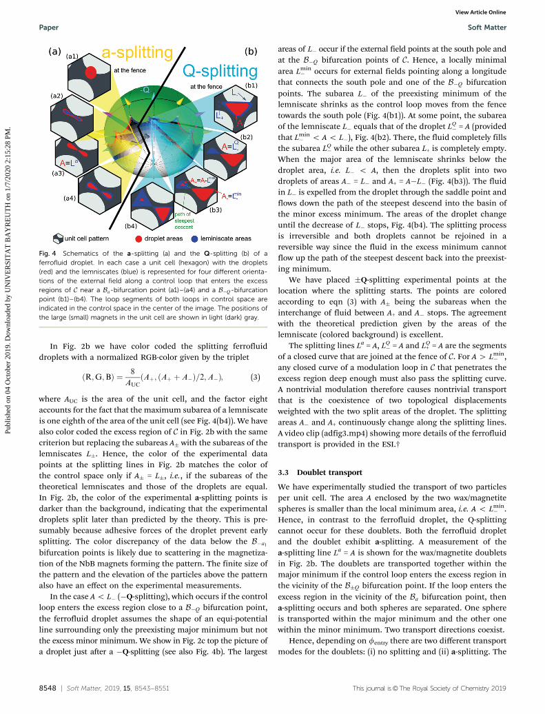
The splitting of a ferrofluid droplet occurs either in anadiabatic way (a-splitting) or irreversibly (Q-splitting). Bothtypes of splitting are schematically represented in Fig. 4. Theferrofluid droplet covers a certain area A of action space when theexternal field enters the excess region of C. A ‘‘minor’’ excessminimum and an excess saddle point are created in the magneticpotential upon the entry of the external field into the excess region.17
The equi-potential line passing through the excess saddle pointis a lemniscate that first winds around the preexisting ‘‘major’’minimum, then passes through the saddle point, and next windsaround the minor excess minimum. Hence, the lemniscatedefines a closed curve of area L = L+ + L� where each of thetwo sub areas, L+ and L�, surrounds a minimum of the potential.At the fence in C, the sub lemniscate area of the minor minimum,L+ = 0 (L� = 0) for a �Q-fence segment (+Q-fence segment)vanishes. At the fence L+ = 0 or L� = 0 and the area occupied bythe ferrofluid droplet can be either larger A 4 L+ + L� or smallerA o L� (A o L+) than that of the preexisting major minimum.
In the case A 4 L+ + L� (a-splitting), which occurs if the loopenters the excess region of C close to a Ba bifurcation point, theferrofluid droplet assumes the shape of an equipotential linecontaining both minima (see Fig. 2c bottom and Fig. 4a). Whenthe loop enters deeper into the excess region of C, the area ofthe lemniscate grows (Fig. 4(a1) and (a2)). At the point wherethe area of the lemniscate is the same as the area of the droplet,L = La = A, both lemniscate subareas La
+ and La� are fully filled
with a ferrofluid (Fig. 4(a3)). When the area of the lemniscategrows beyond that of the droplet, L 4 A, then the droplet splitsinto two droplets of areas A+ = La
+ and A� = La� (Fig. 4(a4)). The
areas of both droplets do not change until the droplets coalesceagain, i.e. no further splitting occurs. The splitting is reversibleif the control loop is reversed and crosses the splitting lineLa = A at exactly the same point.
Fig. 3 Dynamics of the ferrofluid droplets subject to the modulation loops a-i, and �i of Fig. 2. In each image we overlay an image of the droplet beforethe entry into the excess region (brown), at the splitting line (purple) and after recombination at the end of the loop (turquoise). The differentimages correspond to different loops depicted in Fig. 2b with loop a fentry = fexit = 4.4p/6, loop c fentry = 5.5p/6, fexit = 4.4p/6, loop e fentry =6.5p/6, fexit = 4.4p/6, loop g fentry = 7.5p/6, fexit = 4.4p/6 loop i fentry = 8.5p/6, fexit = 4.4p/6 and the inverse loop �i fentry = 4.4p/6, fexit = 8.5p/6. Forloops a and c, two trivial modes coexist. In loops e and g, a transport mode into the �a2 direction coexists with a trivial mode. In loop i, a transport modein the �a2 direction coexists with a transport mode into the �a3 direction. The control loop of �i is the inverse of loop i with two transport modes alonga2 and a3. The red arrows show the transport directions during the splitting of the brown droplet towards the purple droplets. The green arrows show themotion of the two purple droplets as they rejoin into the turquoise droplet. The blue arrow shows the adiabatic motion upon closing the loop in controlspace by returning to the starting point. The displacement after one control loop is the coexistence of the two displacements D+ and D� of the two splitdroplets. The black arrows are sketches of the motion of the droplets. The scale bar is 1 mm. A video clip showing the motion of the droplets is providedin the ESI† (adfig3.mp4).
Soft Matter Paper
Publ
ishe
d on
04
Oct
ober
201
9. D
ownl
oade
d by
UN
IVE
RSI
TA
T B
AY
RE
UT
H o
n 1/
7/20
20 2
:15:
28 P
M.
View Article Online
8548 | Soft Matter, 2019, 15, 8543--8551 This journal is©The Royal Society of Chemistry 2019
In Fig. 2b we have color coded the splitting ferrofluiddroplets with a normalized RGB-color given by the triplet
ðR;G;BÞ ¼ 8
AUCAþ; ðAþ þ A�Þ=2;A�ð Þ; (3)
where AUC is the area of the unit cell, and the factor eightaccounts for the fact that the maximum subarea of a lemniscateis one eighth of the area of the unit cell (see Fig. 4(b4)). We havealso color coded the excess region of C in Fig. 2b with the samecriterion but replacing the subareas A� with the subareas of thelemniscates L�. Hence, the color of the experimental datapoints at the splitting lines in Fig. 2b matches the color ofthe control space only if A� = L�, i.e., if the subareas of thetheoretical lemniscates and those of the droplets are equal.In Fig. 2b, the color of the experimental a-splitting points isdarker than the background, indicating that the experimentaldroplets split later than predicted by the theory. This is pre-sumably because adhesive forces of the droplet prevent earlysplitting. The color discrepancy of the data below the B�a1bifurcation points is likely due to scattering in the magnetiza-tion of the NbB magnets forming the pattern. The finite size ofthe pattern and the elevation of the particles above the patternalso have an effect on the experimental measurements.
In the case A o L� (�Q-splitting), which occurs if the controlloop enters the excess region close to a B�Q bifurcation point,the ferrofluid droplet assumes the shape of an equi-potentialline surrounding only the preexisting major minimum but notthe excess minor minimum. We show in Fig. 2c top the picture ofa droplet just after a �Q-splitting (see also Fig. 4b). The largest
areas of L� occur if the external field points at the south pole andat the B�Q bifurcation points of C. Hence, a locally minimalarea Lmin
� occurs for external fields pointing along a longitudethat connects the south pole and one of the B�Q bifurcationpoints. The subarea L� of the preexisting minimum of thelemniscate shrinks as the control loop moves from the fencetowards the south pole (Fig. 4(b1)). At some point, the subareaof the lemniscate L� equals that of the droplet LQ
� = A (providedthat Lmin
� o A o L�), Fig. 4(b2). There, the fluid completely fillsthe subarea LQ
� while the other subarea L+ is completely empty.When the major area of the lemniscate shrinks below thedroplet area, i.e. L� o A, then the droplets split into twodroplets of areas A� = L� and A+ = A�L� (Fig. 4(b3)). The fluidin L� is expelled from the droplet through the saddle point andflows down the path of the steepest descend into the basin ofthe minor excess minimum. The areas of the droplet changeuntil the decrease of L� stops, Fig. 4(b4). The splitting processis irreversible and both droplets cannot be rejoined in areversible way since the fluid in the excess minimum cannotflow up the path of the steepest descent back into the preexist-ing minimum.
We have placed �Q-splitting experimental points at thelocation where the splitting starts. The points are coloredaccording to eqn (3) with A� being the subareas when theinterchange of fluid between A+ and A� stops. The agreementwith the theoretical prediction given by the areas of thelemniscate (colored background) is excellent.
The splitting lines La = A, LQ� = A and LQ
+ = A are the segmentsof a closed curve that are joined at the fence of C. For A 4 Lmin
� ,any closed curve of a modulation loop in C that penetrates theexcess region deep enough must also pass the splitting curve.A nontrivial modulation therefore causes nontrivial transportthat is the coexistence of two topological displacementsweighted with the two split areas of the droplet. The splittingareas A� and A+ continuously change along the splitting lines.A video clip (adfig3.mp4) showing more details of the ferrofluidtransport is provided in the ESI.†
3.3 Doublet transport
We have experimentally studied the transport of two particlesper unit cell. The area A enclosed by the two wax/magnetitespheres is smaller than the local minimum area, i.e. A o Lmin
� .Hence, in contrast to the ferrofluid droplet, the Q-splittingcannot occur for these doublets. Both the ferrofluid dropletand the doublet exhibit a-splitting. A measurement of thea-splitting line La = A is shown for the wax/magnetite doubletsin Fig. 2b. The doublets are transported together within themajor minimum if the control loop enters the excess region inthe vicinity of the B�Q bifurcation point. If the loop enters theexcess region in the vicinity of the Ba bifurcation point, thena-splitting occurs and both spheres are separated. One sphereis transported within the major minimum and the other onewithin the minor minimum. Two transport directions coexist.
Hence, depending on fentry there are two different transportmodes for the doublets: (i) no splitting and (ii) a-splitting. The
Fig. 4 Schematics of the a-splitting (a) and the Q-splitting (b) of aferrofluid droplet. In each case a unit cell (hexagon) with the droplets(red) and the lemniscates (blue) is represented for four different orienta-tions of the external field along a control loop that enters the excessregions of C near a Ba-bifurcation point (a1)–(a4) and a B�Q-bifurcationpoint (b1)–(b4). The loop segments of both loops in control space areindicated in the control space in the center of the image. The positions ofthe large (small) magnets in the unit cell are shown in light (dark) gray.
Paper Soft Matter
Publ
ishe
d on
04
Oct
ober
201
9. D
ownl
oade
d by
UN
IVE
RSI
TA
T B
AY
RE
UT
H o
n 1/
7/20
20 2
:15:
28 P
M.
View Article Online
This journal is©The Royal Society of Chemistry 2019 Soft Matter, 2019, 15, 8543--8551 | 8549
transition from one transport mode towards the other transportmode occurs at the doublet bifurcation points Bdoublet that arethe intersections of the fence with the a-splitting line La = A fordoublets. Since the spheres have the same size, the areas of thea-splitting transport are equal A� = A+ = A/2. Hence, theexperimental data points for doublet a-splitting all havethe same color, see eqn (3) and Fig. 2b. The color is darkerthan the theoretical background color of the lemniscates.Hence, splitting occurs later in the experiment than predictedby the theory, presumably due to the dipolar attraction betweenthe two spheres as well as due to friction with the bottomsurface. Like the transport of a single sphere, the transport ofdoublets is discrete and therefore topological.
Net displacement. We next analyze the net displacementafter the completion of one entire control loop for all threetypes of objects: single spheres, doublets, and ferrofluid droplets.For all objects, we define the vector of the net displacement
D as the area averaged sum of the two possible displacements.That is
D ¼ DþAþ þ D�A�Aþ þ A�
; (4)
where D� are the net displacement vectors of the two minima inone control loop. Hence, D� are always lattice vectors andD moves along a straight line between the two lattice vectors.
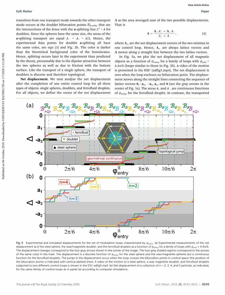
In Fig. 5a, we plot the net displacement of all magneticobjects as a function of fentry for a family of loops with fexit =4.4p/6 (loops similar to those in Fig. 2b). A video of the motionis presented in the ESI† (adfig5.mp4). The net displacement iszero when the loop encloses no bifurcation point. The displace-ment moves along the straight lines connecting the sequence oflattice vectors 0,�a2, �a3, a1, and 0 (see the gray arrows in thecenter of Fig. 5a). The areas A+ and A� are continuous functionsof fentry for the ferrofluid droplet. In contrast, the transported
Fig. 5 Experimental and simulated displacements for the set of modulation loops characterized by fentry. (a) Experimental measurements of the netdisplacement D of the steel sphere, the wax/magnetite doublet, and the ferrofluid droplets as a function of fentry for a family of loops with fexit = 4.4p/6.The displacement changes correspond to the four gray arrows shown in the center of the image. The four gray shaded regions correspond to the arrowsof the same color in the inset. The displacement is a discrete function of fentry for the steel sphere and the wax/magnetite spheres but a continuousfunction for the ferrofluid droplets. The jumps in the displacement occur when the loop crosses the bifurcation points in control space (the position ofthe bifurcation points is indicated with vertical dashed lines). A video of the motion of a steel sphere, a wax magnetite doublet, and ferrofluid dropletssubjected to two different control loops is shown in the ESI† adfig5.mp4. (b) Net displacement of a collection of n = 2, 3, 4, and 5 particles, as indicated,for the same family of control loops as in panel (a) according to computer simulations.
Soft Matter Paper
Publ
ishe
d on
04
Oct
ober
201
9. D
ownl
oade
d by
UN
IVE
RSI
TA
T B
AY
RE
UT
H o
n 1/
7/20
20 2
:15:
28 P
M.
View Article Online
8550 | Soft Matter, 2019, 15, 8543--8551 This journal is©The Royal Society of Chemistry 2019
areas A� for one steel sphere (a wax/magnetite doublet) canonly be integer multiples n = 0,1 (n = 0,1,2) of the area of onesphere. Contrary to the ferrofluid transport, the sphere anddoublet net displacement change discretely with fentry.The number of discrete steps for the doublets is twice thatof a single steel sphere. Hence, the transport of one or twospheres is topological while the transport of the ferrofluid isgeometrical.
3.4 Multiparticle transport
What is the minimum number of particles required for havinggeometrical transport? To address this fundamental question,we have simulated the transport of multiple spheres usingoverdamped Langevin dynamics (note that inertial effects arenegligible). Each unit cell is filled with exactly n particles. Eachparticle is subject to the magnetic potential
U xA;HextðtÞð Þ / �HextðtÞ �Hp xAð Þ; (5)
where Hext(t) is the external field at time t and Hp xAð Þ is themagnetic field, created by the pattern at the position of theparticle xA in action space A, see ref. 22 and 23.
The particles interact via the purely repulsive Weeks–Chandler–Andersen potential
fðrÞ ¼4e
sr
� �12� s
r
� �6þ14
� �r � 21=6s
0 r4 21=6s
8><>: ; (6)
where r is the distance between the particles, e fixes our unit andenergy, and s is the effective particle length that we fix to s/a = 0.2which is the same as in the experiments (transport of singlespheres). We integrate the equations of motion with a time stepdt/T = 10�5, with T being the period of a modulation loop. As thetransport is topological the detailed features of the simulatedparticles are of minor importance and the behavior will not changeusing somewhat different parameters for the simulations. Fig. 5bshows the net displacement of n = 2, 3, 4, 5 spheres. The number ofplateaus in the displacement of n particles per unit cell is n timesthe number of plateaus of a single sphere. This is true providedthat each unit cell is filled with precisely n particles since the resultsdepend on the initial distribution of particles among the differentunit cells. Our simulation results suggest therefore that if preciselythe same number of equally sized ferrofluid particles could bedeposited in each droplet, one would still observe topologicaltransport, albeit with very fine splitting. However, if there isdispersion in the size of particles, the occupation of the unit cells,the number of plateaus and splittings might be significantlyincreased because the number of different geometrically distin-guishable ways to split the droplets into subdroplets is increased.For broad dispersions of sizes we would expect that the transport istopological with a step size that scales with an other power than theinverse of the occupation of the site. Here, we have investigatedonly the case of monodisperse particles.
Note that the experimental fentry and the fentry in thesimulations of the doublet bifurcation points (at which the netdisplacement jumps) differ (Fig. 5a and b). In the experiment, the
spheres do not only interact via excluded volume interactions, butare also subject to long range dipolar interactions. We tried tominimize the effect of dipolar interactions by using the wax/magnetite composite spheres. We have understood the transportproperties under simple conditions, however an in depth under-standing must also include studies of how the transport changeswith polydisperse particle sizes, varying the occupation of unitcells, and with stronger dipolar interactions.
4 Conclusions
We have studied experimentally and with computer simulationsthe transport of paramagnetic particles on top of a magneticlattice, driven by a uniform and time-dependent external magneticfield. The external field performs periodic closed loops. We haveshown that increasing the number of particles within the unit cellof the lattice changes the transport from topological towardsgeometrical.
The transport as a function of a parameter that continuouslycharacterizes a family of control loops is discrete for lowparticle densities and continuous for a macroscopic numberof particles per unit cell (ferrofluid droplet). More possibilitiesto split or disjoin soft matter assemblies increase the numberof bifurcation points in control space with more transportmodes in action space that are separated by finer steps. It isthe number of possibilities that eventually changes the trans-port from topological to geometrical.
A ferrofluid is a colloidal suspension of nanoparticles.Rendering the transport of this soft matter system as robustas the solid particle transport, the magnetic pattern must bedownscaled to the nanometer range. In such downscalingstudies, we have already shown the topological nature of thetransport of a colloidal dispersion of micron-sized magneticcolloids.17,22
Conflicts of interest
There are no conflicts to declare.
Appendix
Here we provide some details of the experimental setup. Themagnetic hexagonal lattice (Fig. 1a) consists of large (l) andsmall (s) cylindrical magnets of height h = 2 mm, diametersdl = 3 mm and ds = 2 mm, and remanences m0Ml = 1.19 T andm0Ms = 1.35 T, with m0 being the permeability of free space. Theresulting lattice with two primitive lattice vectors of lengtha = 4.33 mm is mechanically metastable in zero externalmagnetic field. Therefore, we need to fix the metastablearrangement with an epoxy resin placed in the voids and inthe two dimensional surroundings of the pattern. The patternis then stable also in the presence of an external field. Thepattern is put on a support and covered with a transparentPMMA spacer of thickness z = 1–1.5 mm (Fig. 1c). It may besprayed with PTFE to suppress wetting with the ferrofluid
Paper Soft Matter
Publ
ishe
d on
04
Oct
ober
201
9. D
ownl
oade
d by
UN
IVE
RSI
TA
T B
AY
RE
UT
H o
n 1/
7/20
20 2
:15:
28 P
M.
View Article Online
This journal is©The Royal Society of Chemistry 2019 Soft Matter, 2019, 15, 8543--8551 | 8551
droplets. Additionally, a white illuminated foil can be placedunderneath the PMMA.
We either place one steel sphere of diameter 2r = 1 mm ortwo spheres of diameter 2r = 0.5 mm consisting of a 10 : 1weight percent mixture of wax and magnetite on top of thespacer. Alternatively, we place two fluids, a nonmagnetic fluid(Galden) and an aqueous ferrofluid immiscible with the Galdenat a volume ratio Galden/ferrofluid of 152 : 1, on top of the PTFEand close to the compartment with a transparent lid.
The goniometer is set up at an angle of 45 degrees to ensurethat the relevant motion is not affected by the restrictionsof motion of the goniometer caused by the support. The twolarge NbB-magnets that generate the external field have adiameter dext = 60 mm, a thickness text = 10 mm, anda remanence of m0Mext = 1.28 T and they are separated by adistance 2R = 120 mm.
Acknowledgements
Scientific discussion with Michel Lonne is highly appreciated.
References
1 S.-Q. Shen, Topological insulators: Dirac equation in condensedmatters, Springer Science, and Business Media, 2013.
2 J. Anandan, J. Christian and K. Wanelik, Resource LetterGPP-1: Geometric Phases in Physics, Am. J. Phys., 1997, 65,180–185.
3 M. V. Berry, Quantum phase factors accompanying adia-batic changes, Proc. R. Soc. London, Ser. A, 1984, A392,45–57.
4 J. H. Hannay, Angle variable holonomy in adiabatic excursionof an integrable Hamiltonian, J. Phys., 1985, A18, 221–230.
5 A. Shapere and F. Wilczek, Geometry of self-propulsion atlow Reynolds number, J. Fluid Mech., 1989, 198, 557–585.
6 A. Shapere and F. Wilczek, Efficiency of self-propulsion atlow Reynolds number, J. Fluid Mech., 1989, 198, 587–599.
7 M. Z. Hasan and C. L. Kane, Colloquium: Topologicalinsulators, Rev. Mod. Phys., 2010, 82, 3045–3067.
8 D. Harland and N. S. Manton, Rolling Skyrmions and thenuclear spin-orbit force, Nucl. Phys. B, 2018, 935, 210–241.
9 K. v. Klitzing, G. Dorda and M. Pepper, New method forhigh-accuracy determination of the fine-structure constantbased on quantized Hall resistance, Phys. Rev. Lett., 1980,45, 494–497.
10 M. C. Rechtsman, J. M. Zeuner, Y. Plotnik, Y. Lumer,D. Podolsky, F. Dreisow, S. Nolte, M. Segev and A. Szameit,
Photonic Floquet topological insulators, Nature, 2013, 496,196–200.
11 M. Xiao, G. Ma, Z. Yang, P. Sheng, Z. Q. Zhang andC. T. Chan, Geometric phase and band inversion in periodicacoustic systems, Nat. Phys., 2015, 11, 240–244.
12 J. Paulose, B. G. Chen and V. Vitelli, Topological modesbound to dislocations in mechanical metamaterials, Nat.Phys., 2015, 11, 153–156.
13 C. L. Kane and T. C. Lubensky, Topological boundary modesin isostatic lattices, Nat. Phys., 2014, 10, 39–45.
14 L. M. Nash, D. Kleckner, A. Read, V. Vitelli, A. M. Turner andW. T. M. Irvine, Topological mechanics of gyroscopic meta-materials, Proc. Natl. Acad. Sci. U. S. A., 2015, 112, 14495–14500.
15 S. D. Huber, Topological mechanics, Nat. Phys., 2016, 12,621–623.
16 A. Murugan and S. Vaikuntanathan, Topologically protectedmodes in non-equilibrium stochastic systems, Nat. Commun.,2017, 8, 13881.
17 J. Loehr, M. Loenne, A. Ernst, D. de las Heras and T. M.Fischer, Topological protection of multiparticle dissipativetransport, Nat. Commun., 2016, 7, 11745.
18 Y. Xiong, Why does bulk boundary correspondence fail insome non-hermitian topological models, J. Phys. Commun.,2018, 2, 035043.
19 S. Yao and Z. Wang, Edge States and Topological Invariantsof Non-Hermitian Systems, Phys. Rev. Lett., 2018, 121,086803.
20 F. K. Kunst, E. Edvardsson, J. C. Budich and E. J. Bergholtz,Biorthogonal bulk-boundary correspondence in non-Hermitiansystems, Phys. Rev. Lett., 2018, 121, 026808.
21 A. M. E. B. Rossi, J. Bugase and T. M. Fischer, MacroscopicFloquet topological crystalline steel and superconductorpump, Europhys. Lett., 2017, 119, 40001.
22 J. Loehr, D. de las Heras, M. Loenne, J. Bugase, A. Jarosz,M. Urbaniak, F. Stobiecki, A. Tomita, R. Huhnstock, I. Koch,A. Ehresmann, D. Holzinger and T. M. Fischer, Latticesymmetries and the topologically protected transport ofcolloidal particles, Soft Matter, 2017, 13, 5044–5075.
23 D. de las Heras, J. Loehr, M. Loenne and T. M. Fischer,Topologically protected colloidal transport above a squaremagnetic lattice, New J. Phys., 2016, 18, 105009.
24 D. P. Jackson, R. E. Goldstein and A. O. Cebers, Hydro-dynamics of fingering instabilities in dipolar fluids, Phys.Rev. E: Stat. Phys., Plasmas, Fluids, Relat. Interdiscip. Top.,1994, 50, 298.
25 N. Wilke, J. Bugase, L.-M. Treffenstadt and T. M. Fischer,Wrinkled labyrinths in critical demixing ferrofluid, SoftMatter, 2017, 13, 7307–7311.
Soft Matter Paper
Publ
ishe
d on
04
Oct
ober
201
9. D
ownl
oade
d by
UN
IVE
RSI
TA
T B
AY
RE
UT
H o
n 1/
7/20
20 2
:15:
28 P
M.
View Article Online