Embed Size (px)
Citation preview
Hw
Aa
b
F
a
ARRA
KHPCTR
1
ttastclfa
cd(h6ntwd
0d
Journal of Materials Processing Technology 209 (2009) 5262–5270
Contents lists available at ScienceDirect
Journal of Materials Processing Technology
journa l homepage: www.e lsev ier .com/ locate / jmatprotec
ard turning in continuous and interrupted cut with PCBN andhisker-reinforced cutting tools
dilson José de Oliveiraa, Anselmo Eduardo Dinizb,∗, Davi Janini Ursolinob
Die and Mold Research Group, Educational Society of Santa Catarina, IST/SOCIESC, Joinville, SC 89206-001, BrazilDepartment of Manufacturing Engineering, Faculty of Mechanical Engineering, University of Campinas,EM/UNICAMP, Campinas CP 6122, 13083-970, SP, Brazil
r t i c l e i n f o
rticle history:eceived 19 January 2009eceived in revised form 17 March 2009ccepted 19 March 2009
a b s t r a c t
PCBN (polycrystalline cubic boron nitride) is the most widely used material for tools employed in hard-ened steel turning applications due to its high hardness, wear resistance and thermal stability. However,its high costs severely limit its use. Alumina-based ceramics reinforced with whiskers, an alternative andless expensive material for these tools, has been used successfully in turning interrupted surfaces. The
eywords:ard turningCBN toolseramic toolsool wearoughness
objective of this work is to investigate the conditions under which PCBN and ceramic tools can promoteoptimal results in the turning of hardened steel with continuous and interrupted surfaces. These toolswere used in the radial turning of hardened steel with three types of surfaces: continuous surfaces andsurfaces with 4 and 8 interruptions. The results indicated that, in continuous turning, the longest tool lifewas achieved using PCBN, but similar tool longevity was attained in interrupted turning using both PCBNand ceramic. In terms of roughness, the PCBN tools showed better results for continuous and interruptedsurfaces.
. Introduction
Parts with hardness exceeding 45 HRC can be machined by hardurning, which provides surface roughness, dimensional and shapeolerances similar to those achieved in grinding. High flexibilitynd the ability to cut complex geometries with a single machineetup are the main technological advantages of hard turning overhe grinding process. Moreover, the hard turning process is usuallyarried out without coolant/lubricant, thus eliminating the prob-ems of storage, handling, and disposal of cutting fluid, and probablyavoring the health of machine operators (Klocke et al., 2005; Huangnd Dawson, 2005).
PCBN (polycrystalline cubic boron nitride) is the material mostommonly used in tools for hardened steel turning applicationsue to its high hardness, wear resistance and thermal stabilityMore et al., 2006). PCBN tools are usually classified in two grades:igh PCBN content (around 90%) and low PCBN content (around0%), with a ceramic phase added to the material, usually titanium
itride. Tools with high PCBN content display greater toughnesshan those with an added ceramic phase. On the other hand, PCBNith a ceramic phase added to the material is more resistant toiffusion wear, which is very important, especially in continuous∗ Corresponding author. Tel.: +55 19 3521 3213; fax: +55 19 3289 3722.E-mail address: [email protected] (A.E. Diniz).
924-0136/$ – see front matter © 2009 Elsevier B.V. All rights reserved.oi:10.1016/j.jmatprotec.2009.03.012
© 2009 Elsevier B.V. All rights reserved.
turning. Studies using these two classes of PCBN tools in contin-uous turning (Diniz and Oliveira, 2008; Ko and Him, 2001) haveshown that, when the part and tool fixturing system were rigid toprevent either microchipping or breakage on the cutting edge, thelife of the PCBN tool with a ceramic phase was longer than thatof the tool with high PCBN content. This fact is attributed to theadded ceramic phase in PCBN material, which increases the tool’schemical stability, reducing the tendency for diffusion of tool par-ticles into metallic elements of the chip, despite the decrease in thethermal conductivity of the tool material.
In industrial applications, many components that are quenchedand tempered before the finish turning operation have surfacesinterrupted by holes, lubrication channels, splines and key slots(Juvinall and Marshek, 1999). Interrupted turning of hardened sur-faces imposes extra difficulties on machining operations. In suchcases, a PCBN rather than a ceramic tool is preferable, due to its highhardness allied to moderate toughness. Diniz and Oliveira (2008)studied the feasibility of turning three different types of surface(continuous, semi-interrupted and interrupted) using two gradesof PCBN tools (low PCBN content plus ceramic phase, and highPCBN content). Contrary to their expectations, the tools presented
a longer life when turning interrupted surfaces than when turn-ing continuous surfaces, demonstrating that PCBN is sufficientlyresistant to the impacts inherent in the cutting of interrupted sur-faces. Their results also showed that even tools with low PCBNcontent, which are presumably less tough, were able to with-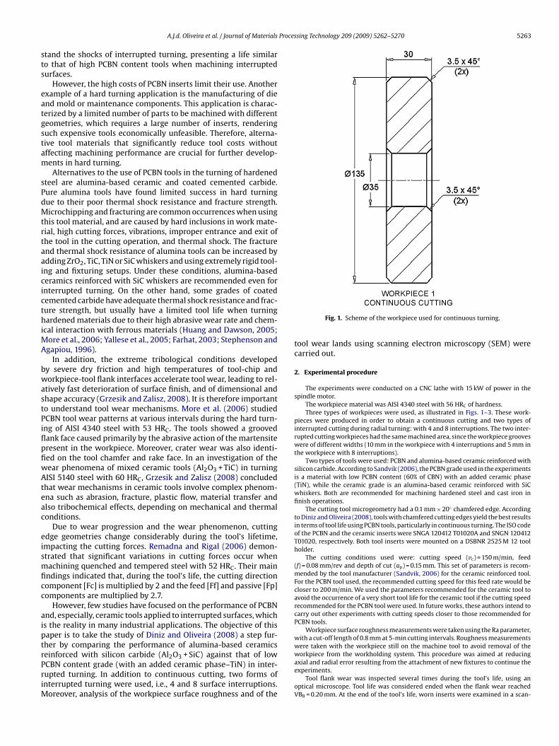
Processing Technology 209 (2009) 5262–5270 5263
sts
eatgstam
sPdMtrtaaicicthiMA
bwastPiflpfiwAteac
eismficc
aiptrPriM
A.J.d. Oliveira et al. / Journal of Materials
tand the shocks of interrupted turning, presenting a life similaro that of high PCBN content tools when machining interruptedurfaces.
However, the high costs of PCBN inserts limit their use. Anotherxample of a hard turning application is the manufacturing of diend mold or maintenance components. This application is charac-erized by a limited number of parts to be machined with differenteometries, which requires a large number of inserts, renderinguch expensive tools economically unfeasible. Therefore, alterna-ive tool materials that significantly reduce tool costs withoutffecting machining performance are crucial for further develop-ents in hard turning.Alternatives to the use of PCBN tools in the turning of hardened
teel are alumina-based ceramic and coated cemented carbide.ure alumina tools have found limited success in hard turningue to their poor thermal shock resistance and fracture strength.icrochipping and fracturing are common occurrences when using
his tool material, and are caused by hard inclusions in work mate-ial, high cutting forces, vibrations, improper entrance and exit ofhe tool in the cutting operation, and thermal shock. The fracturend thermal shock resistance of alumina tools can be increased bydding ZrO2, TiC, TiN or SiC whiskers and using extremely rigid tool-ng and fixturing setups. Under these conditions, alumina-basederamics reinforced with SiC whiskers are recommended even fornterrupted turning. On the other hand, some grades of coatedemented carbide have adequate thermal shock resistance and frac-ure strength, but usually have a limited tool life when turningardened materials due to their high abrasive wear rate and chem-
cal interaction with ferrous materials (Huang and Dawson, 2005;ore et al., 2006; Yallese et al., 2005; Farhat, 2003; Stephenson and
gapiou, 1996).In addition, the extreme tribological conditions developed
y severe dry friction and high temperatures of tool-chip andorkpiece-tool flank interfaces accelerate tool wear, leading to rel-
tively fast deterioration of surface finish, and of dimensional andhape accuracy (Grzesik and Zalisz, 2008). It is therefore importanto understand tool wear mechanisms. More et al. (2006) studiedCBN tool wear patterns at various intervals during the hard turn-ng of AISI 4340 steel with 53 HRC. The tools showed a groovedank face caused primarily by the abrasive action of the martensiteresent in the workpiece. Moreover, crater wear was also identi-ed on the tool chamfer and rake face. In an investigation of theear phenomena of mixed ceramic tools (Al2O3 + TiC) in turningISI 5140 steel with 60 HRC, Grzesik and Zalisz (2008) concluded
hat wear mechanisms in ceramic tools involve complex phenom-na such as abrasion, fracture, plastic flow, material transfer andlso tribochemical effects, depending on mechanical and thermalonditions.
Due to wear progression and the wear phenomenon, cuttingdge geometries change considerably during the tool’s lifetime,mpacting the cutting forces. Remadna and Rigal (2006) demon-trated that significant variations in cutting forces occur whenachining quenched and tempered steel with 52 HRC. Their main
ndings indicated that, during the tool’s life, the cutting directionomponent [Fc] is multiplied by 2 and the feed [Ff] and passive [Fp]omponents are multiplied by 2.7.
However, few studies have focused on the performance of PCBNnd, especially, ceramic tools applied to interrupted surfaces, whichs the reality in many industrial applications. The objective of thisaper is to take the study of Diniz and Oliveira (2008) a step fur-her by comparing the performance of alumina-based ceramics
einforced with silicon carbide (Al2O3 + SiC) against that of lowCBN content grade (with an added ceramic phase–TiN) in inter-upted turning. In addition to continuous cutting, two forms ofnterrupted turning were used, i.e., 4 and 8 surface interruptions.oreover, analysis of the workpiece surface roughness and of the
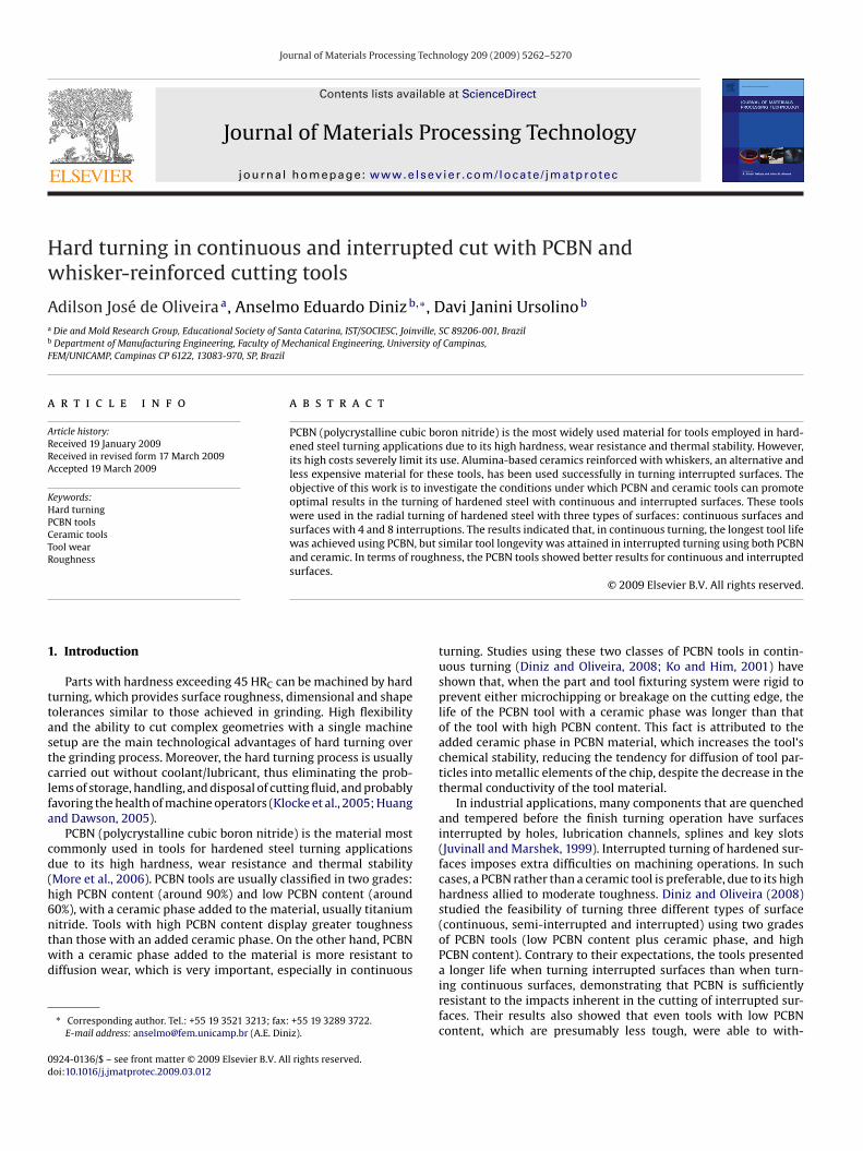
Fig. 1. Scheme of the workpiece used for continuous turning.
tool wear lands using scanning electron microscopy (SEM) werecarried out.
2. Experimental procedure
The experiments were conducted on a CNC lathe with 15 kW of power in thespindle motor.
The workpiece material was AISI 4340 steel with 56 HRC of hardness.Three types of workpieces were used, as illustrated in Figs. 1–3. These work-
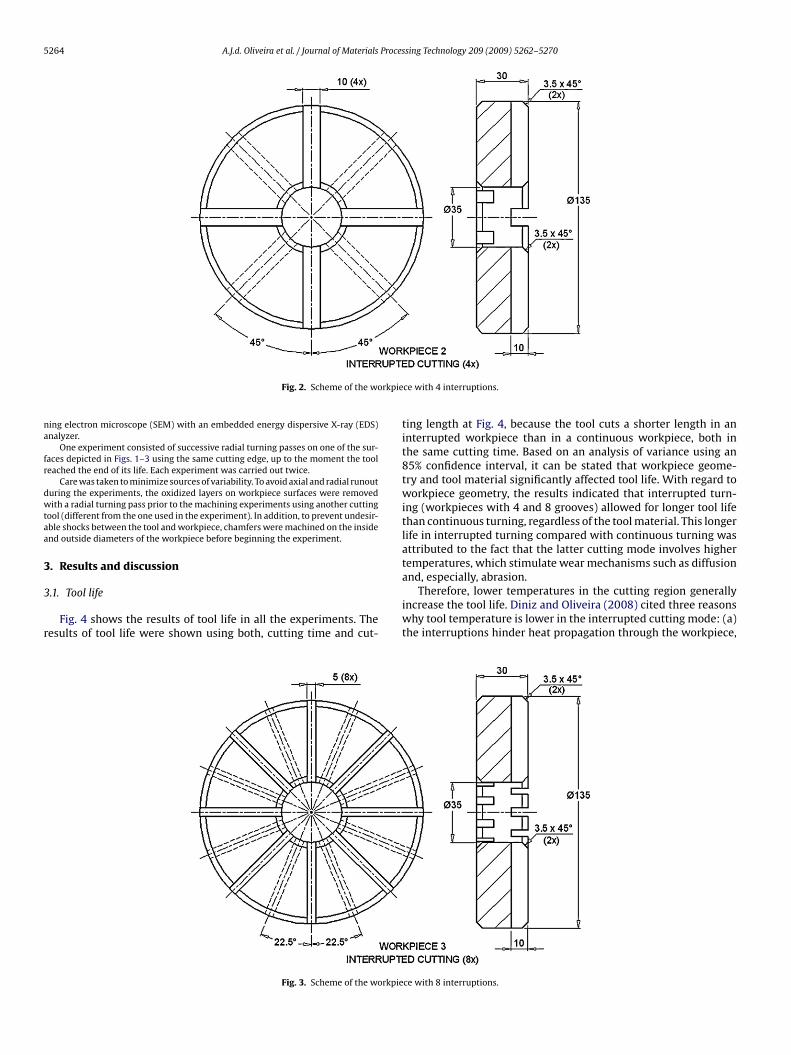
pieces were produced in order to obtain a continuous cutting and two types ofinterrupted cutting during radial turning: with 4 and 8 interruptions. The two inter-rupted cutting workpieces had the same machined area, since the workpiece grooveswere of different widths (10 mm in the workpiece with 4 interruptions and 5 mm inthe workpiece with 8 interruptions).
Two types of tools were used: PCBN and alumina-based ceramic reinforced withsilicon carbide. According to Sandvik (2006), the PCBN grade used in the experimentsis a material with low PCBN content (60% of CBN) with an added ceramic phase(TiN), while the ceramic grade is an alumina-based ceramic reinforced with SiCwhiskers. Both are recommended for machining hardened steel and cast iron infinish operations.
The cutting tool microgeometry had a 0.1 mm × 20◦ chamfered edge. Accordingto Diniz and Oliveira (2008), tools with chamfered cutting edges yield the best resultsin terms of tool life using PCBN tools, particularly in continuous turning. The ISO codeof the PCBN and the ceramic inserts were SNGA 120412 T01020A and SNGN 120412T01020, respectively. Both tool inserts were mounted on a DSBNR 2525 M 12 toolholder.
The cutting conditions used were: cutting speed (vc) = 150 m/min, feed(f) = 0.08 mm/rev and depth of cut (ap) = 0.15 mm. This set of parameters is recom-mended by the tool manufacturer (Sandvik, 2006) for the ceramic reinforced tool.For the PCBN tool used, the recommended cutting speed for this feed rate would becloser to 200 m/min. We used the parameters recommended for the ceramic tool toavoid the occurrence of a very short tool life for the ceramic tool if the cutting speedrecommended for the PCBN tool were used. In future works, these authors intend tocarry out other experiments with cutting speeds closer to those recommended forPCBN tools.
Workpiece surface roughness measurements were taken using the Ra parameter,with a cut-off length of 0.8 mm at 5-min cutting intervals. Roughness measurementswere taken with the workpiece still on the machine tool to avoid removal of theworkpiece from the workholding system. This procedure was aimed at reducing
axial and radial error resulting from the attachment of new fixtures to continue theexperiments.Tool flank wear was inspected several times during the tool’s life, using anoptical microscope. Tool life was considered ended when the flank wear reachedVBB = 0.20 mm. At the end of the tool’s life, worn inserts were examined in a scan-
5264 A.J.d. Oliveira et al. / Journal of Materials Processing Technology 209 (2009) 5262–5270
rkpie
na
fr
dwtaa
3
3
r
Fig. 2. Scheme of the wo
ing electron microscope (SEM) with an embedded energy dispersive X-ray (EDS)nalyzer.
One experiment consisted of successive radial turning passes on one of the sur-aces depicted in Figs. 1–3 using the same cutting edge, up to the moment the tooleached the end of its life. Each experiment was carried out twice.
Care was taken to minimize sources of variability. To avoid axial and radial runouturing the experiments, the oxidized layers on workpiece surfaces were removedith a radial turning pass prior to the machining experiments using another cutting
ool (different from the one used in the experiment). In addition, to prevent undesir-ble shocks between the tool and workpiece, chamfers were machined on the insidend outside diameters of the workpiece before beginning the experiment.
. Results and discussion
.1. Tool life
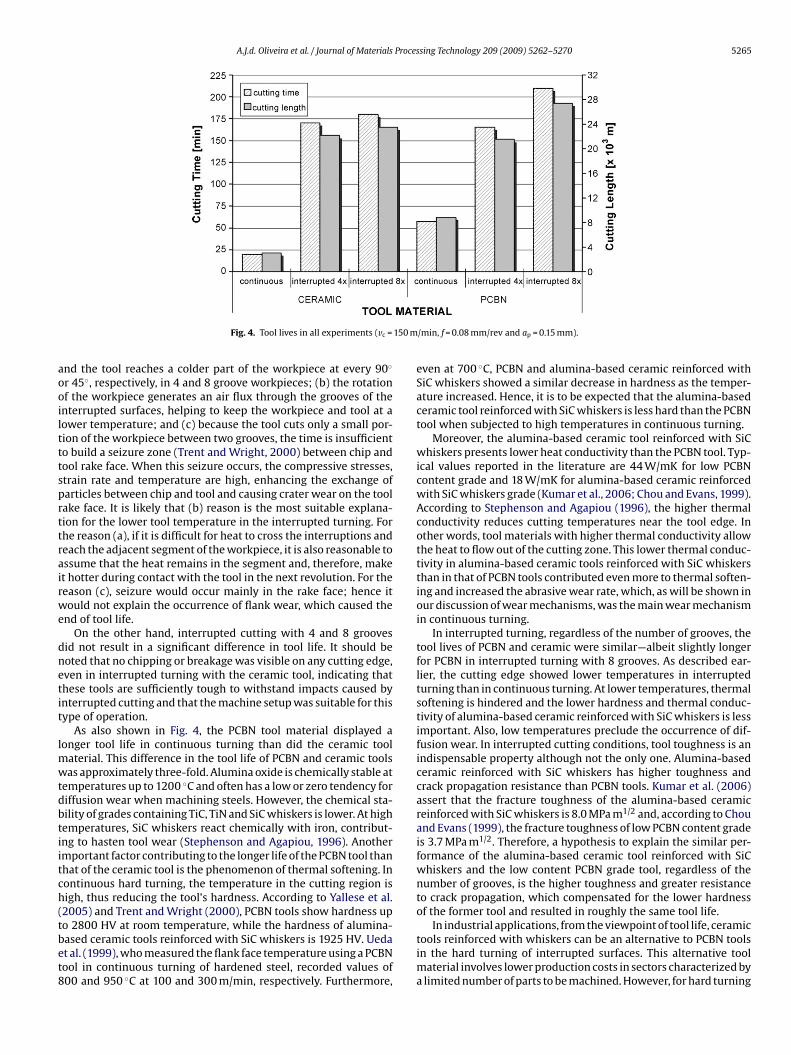
Fig. 4 shows the results of tool life in all the experiments. Theesults of tool life were shown using both, cutting time and cut-
Fig. 3. Scheme of the workpie
ce with 4 interruptions.
ting length at Fig. 4, because the tool cuts a shorter length in aninterrupted workpiece than in a continuous workpiece, both inthe same cutting time. Based on an analysis of variance using an85% confidence interval, it can be stated that workpiece geome-try and tool material significantly affected tool life. With regard toworkpiece geometry, the results indicated that interrupted turn-ing (workpieces with 4 and 8 grooves) allowed for longer tool lifethan continuous turning, regardless of the tool material. This longerlife in interrupted turning compared with continuous turning wasattributed to the fact that the latter cutting mode involves highertemperatures, which stimulate wear mechanisms such as diffusion
and, especially, abrasion.Therefore, lower temperatures in the cutting region generallyincrease the tool life. Diniz and Oliveira (2008) cited three reasonswhy tool temperature is lower in the interrupted cutting mode: (a)the interruptions hinder heat propagation through the workpiece,
ce with 8 interruptions.
A.J.d. Oliveira et al. / Journal of Materials Processing Technology 209 (2009) 5262–5270 5265
150 m
aooiltttsprttrairwe
dnetit
lmwtdbtiitch(tbet8
Fig. 4. Tool lives in all experiments (vc =
nd the tool reaches a colder part of the workpiece at every 90◦
r 45◦, respectively, in 4 and 8 groove workpieces; (b) the rotationf the workpiece generates an air flux through the grooves of thenterrupted surfaces, helping to keep the workpiece and tool at aower temperature; and (c) because the tool cuts only a small por-ion of the workpiece between two grooves, the time is insufficiento build a seizure zone (Trent and Wright, 2000) between chip andool rake face. When this seizure occurs, the compressive stresses,train rate and temperature are high, enhancing the exchange ofarticles between chip and tool and causing crater wear on the toolake face. It is likely that (b) reason is the most suitable explana-ion for the lower tool temperature in the interrupted turning. Forhe reason (a), if it is difficult for heat to cross the interruptions andeach the adjacent segment of the workpiece, it is also reasonable tossume that the heat remains in the segment and, therefore, maket hotter during contact with the tool in the next revolution. For theeason (c), seizure would occur mainly in the rake face; hence itould not explain the occurrence of flank wear, which caused the
nd of tool life.On the other hand, interrupted cutting with 4 and 8 grooves
id not result in a significant difference in tool life. It should beoted that no chipping or breakage was visible on any cutting edge,ven in interrupted turning with the ceramic tool, indicating thathese tools are sufficiently tough to withstand impacts caused bynterrupted cutting and that the machine setup was suitable for thisype of operation.
As also shown in Fig. 4, the PCBN tool material displayed aonger tool life in continuous turning than did the ceramic tool
aterial. This difference in the tool life of PCBN and ceramic toolsas approximately three-fold. Alumina oxide is chemically stable at
emperatures up to 1200 ◦C and often has a low or zero tendency foriffusion wear when machining steels. However, the chemical sta-ility of grades containing TiC, TiN and SiC whiskers is lower. At highemperatures, SiC whiskers react chemically with iron, contribut-ng to hasten tool wear (Stephenson and Agapiou, 1996). Anothermportant factor contributing to the longer life of the PCBN tool thanhat of the ceramic tool is the phenomenon of thermal softening. Inontinuous hard turning, the temperature in the cutting region isigh, thus reducing the tool’s hardness. According to Yallese et al.2005) and Trent and Wright (2000), PCBN tools show hardness up
o 2800 HV at room temperature, while the hardness of alumina-ased ceramic tools reinforced with SiC whiskers is 1925 HV. Uedat al. (1999), who measured the flank face temperature using a PCBNool in continuous turning of hardened steel, recorded values of00 and 950 ◦C at 100 and 300 m/min, respectively. Furthermore,/min, f = 0.08 mm/rev and ap = 0.15 mm).
even at 700 ◦C, PCBN and alumina-based ceramic reinforced withSiC whiskers showed a similar decrease in hardness as the temper-ature increased. Hence, it is to be expected that the alumina-basedceramic tool reinforced with SiC whiskers is less hard than the PCBNtool when subjected to high temperatures in continuous turning.
Moreover, the alumina-based ceramic tool reinforced with SiCwhiskers presents lower heat conductivity than the PCBN tool. Typ-ical values reported in the literature are 44 W/mK for low PCBNcontent grade and 18 W/mK for alumina-based ceramic reinforcedwith SiC whiskers grade (Kumar et al., 2006; Chou and Evans, 1999).According to Stephenson and Agapiou (1996), the higher thermalconductivity reduces cutting temperatures near the tool edge. Inother words, tool materials with higher thermal conductivity allowthe heat to flow out of the cutting zone. This lower thermal conduc-tivity in alumina-based ceramic tools reinforced with SiC whiskersthan in that of PCBN tools contributed even more to thermal soften-ing and increased the abrasive wear rate, which, as will be shown inour discussion of wear mechanisms, was the main wear mechanismin continuous turning.
In interrupted turning, regardless of the number of grooves, thetool lives of PCBN and ceramic were similar—albeit slightly longerfor PCBN in interrupted turning with 8 grooves. As described ear-lier, the cutting edge showed lower temperatures in interruptedturning than in continuous turning. At lower temperatures, thermalsoftening is hindered and the lower hardness and thermal conduc-tivity of alumina-based ceramic reinforced with SiC whiskers is lessimportant. Also, low temperatures preclude the occurrence of dif-fusion wear. In interrupted cutting conditions, tool toughness is anindispensable property although not the only one. Alumina-basedceramic reinforced with SiC whiskers has higher toughness andcrack propagation resistance than PCBN tools. Kumar et al. (2006)assert that the fracture toughness of the alumina-based ceramicreinforced with SiC whiskers is 8.0 MPa m1/2 and, according to Chouand Evans (1999), the fracture toughness of low PCBN content gradeis 3.7 MPa m1/2. Therefore, a hypothesis to explain the similar per-formance of the alumina-based ceramic tool reinforced with SiCwhiskers and the low content PCBN grade tool, regardless of thenumber of grooves, is the higher toughness and greater resistanceto crack propagation, which compensated for the lower hardnessof the former tool and resulted in roughly the same tool life.
In industrial applications, from the viewpoint of tool life, ceramictools reinforced with whiskers can be an alternative to PCBN toolsin the hard turning of interrupted surfaces. This alternative toolmaterial involves lower production costs in sectors characterized bya limited number of parts to be machined. However, for hard turning
5266 A.J.d. Oliveira et al. / Journal of Materials Processing Technology 209 (2009) 5262–5270
each e
wcr
ottoosIo
3
nefsfw
foAatcart
t
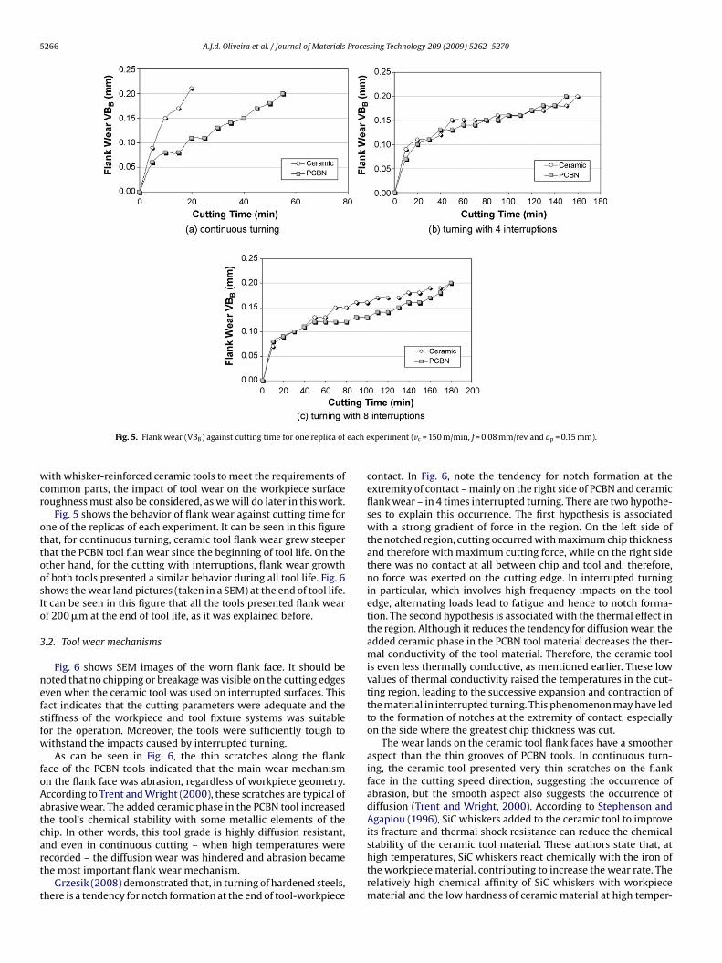
Fig. 5. Flank wear (VBB) against cutting time for one replica of
ith whisker-reinforced ceramic tools to meet the requirements ofommon parts, the impact of tool wear on the workpiece surfaceoughness must also be considered, as we will do later in this work.
Fig. 5 shows the behavior of flank wear against cutting time forne of the replicas of each experiment. It can be seen in this figurehat, for continuous turning, ceramic tool flank wear grew steeperhat the PCBN tool flan wear since the beginning of tool life. On thether hand, for the cutting with interruptions, flank wear growthf both tools presented a similar behavior during all tool life. Fig. 6hows the wear land pictures (taken in a SEM) at the end of tool life.t can be seen in this figure that all the tools presented flank wearf 200 �m at the end of tool life, as it was explained before.
.2. Tool wear mechanisms
Fig. 6 shows SEM images of the worn flank face. It should beoted that no chipping or breakage was visible on the cutting edgesven when the ceramic tool was used on interrupted surfaces. Thisact indicates that the cutting parameters were adequate and thetiffness of the workpiece and tool fixture systems was suitableor the operation. Moreover, the tools were sufficiently tough toithstand the impacts caused by interrupted turning.
As can be seen in Fig. 6, the thin scratches along the flankace of the PCBN tools indicated that the main wear mechanismn the flank face was abrasion, regardless of workpiece geometry.ccording to Trent and Wright (2000), these scratches are typical ofbrasive wear. The added ceramic phase in the PCBN tool increasedhe tool’s chemical stability with some metallic elements of thehip. In other words, this tool grade is highly diffusion resistant,
nd even in continuous cutting – when high temperatures wereecorded – the diffusion wear was hindered and abrasion becamehe most important flank wear mechanism.Grzesik (2008) demonstrated that, in turning of hardened steels,here is a tendency for notch formation at the end of tool-workpiece
xperiment (vc = 150 m/min, f = 0.08 mm/rev and ap = 0.15 mm).
contact. In Fig. 6, note the tendency for notch formation at theextremity of contact – mainly on the right side of PCBN and ceramicflank wear – in 4 times interrupted turning. There are two hypothe-ses to explain this occurrence. The first hypothesis is associatedwith a strong gradient of force in the region. On the left side ofthe notched region, cutting occurred with maximum chip thicknessand therefore with maximum cutting force, while on the right sidethere was no contact at all between chip and tool and, therefore,no force was exerted on the cutting edge. In interrupted turningin particular, which involves high frequency impacts on the tooledge, alternating loads lead to fatigue and hence to notch forma-tion. The second hypothesis is associated with the thermal effect inthe region. Although it reduces the tendency for diffusion wear, theadded ceramic phase in the PCBN tool material decreases the ther-mal conductivity of the tool material. Therefore, the ceramic toolis even less thermally conductive, as mentioned earlier. These lowvalues of thermal conductivity raised the temperatures in the cut-ting region, leading to the successive expansion and contraction ofthe material in interrupted turning. This phenomenon may have ledto the formation of notches at the extremity of contact, especiallyon the side where the greatest chip thickness was cut.
The wear lands on the ceramic tool flank faces have a smootheraspect than the thin grooves of PCBN tools. In continuous turn-ing, the ceramic tool presented very thin scratches on the flankface in the cutting speed direction, suggesting the occurrence ofabrasion, but the smooth aspect also suggests the occurrence ofdiffusion (Trent and Wright, 2000). According to Stephenson andAgapiou (1996), SiC whiskers added to the ceramic tool to improveits fracture and thermal shock resistance can reduce the chemical
stability of the ceramic tool material. These authors state that, athigh temperatures, SiC whiskers react chemically with the iron ofthe workpiece material, contributing to increase the wear rate. Therelatively high chemical affinity of SiC whiskers with workpiecematerial and the low hardness of ceramic material at high temper-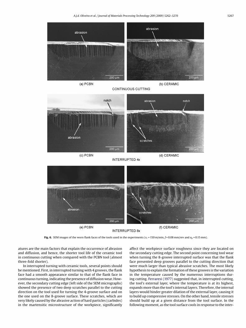
A.J.d. Oliveira et al. / Journal of Materials Processing Technology 209 (2009) 5262–5270 5267
the ex
aait
bfcesdtvi
Fig. 6. SEM images of the worn flank faces of the tools used in
tures are the main factors that explain the occurrence of abrasionnd diffusion, and hence, the shorter tool life of the ceramic tooln continuous cutting when compared with the PCBN tool (almosthree-fold shorter).
In interrupted turning with ceramic tools, several points shoulde mentioned. First, in interrupted turning with 4 grooves, the flankace had a smooth appearance similar to that of the flank face inontinuous turning, indicating the presence of diffusion wear. How-ver, the secondary cutting edge (left side of the SEM micrographs)
howed the presence of two deep scratches parallel to the cuttingirection on the tool used for turning the 4-groove surface and onhe one used on the 8-groove surface. These scratches, which areery likely caused by the abrasive action of hard particles (carbides)n the martensitic microstructure of the workpiece, significantlyperiments (vc = 150 m/min, f = 0.08 mm/rev and ap = 0.15 mm).
affect the workpiece surface roughness since they are located onthe secondary cutting edge. The second point concerning tool wearwhen turning the 8-groove interrupted surface was that the flankface presented deep grooves parallel to the cutting direction thatwere much larger than typical abrasive scratches. The most likelyhypothesis to explain the formation of these grooves is the variationin the temperature caused by the numerous interruptions dur-ing cutting. Ferraresi (1977) suggested that, in interrupted cutting,the tool’s external layer, where the temperature is at its highest,
expands more than the tool’s internal layers. Therefore, the internallayers would hinder greater dilation of the external layer, causing itto build up compressive stresses. On the other hand, tensile stressesshould build up at a given distance from the tool surface. In thefollowing moment, as the tool surface cools in response to the inter-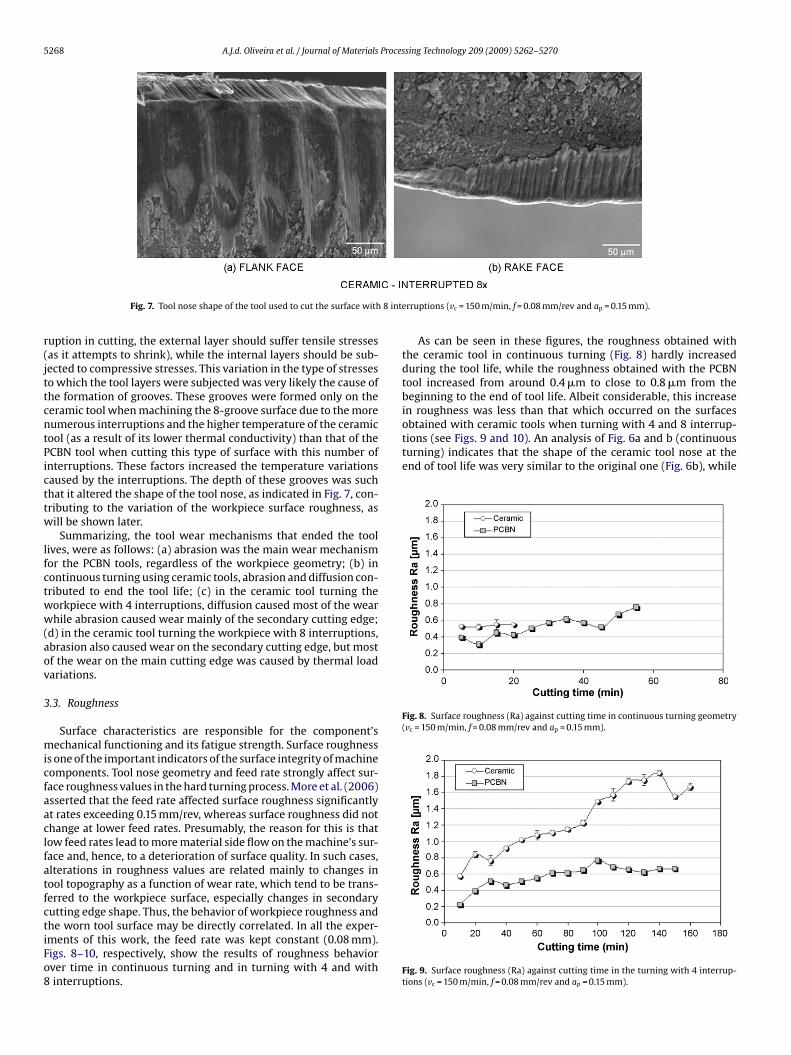
5268 A.J.d. Oliveira et al. / Journal of Materials Processing Technology 209 (2009) 5262–5270
8 int
r(jttcntPicttw
lfctww(aov
3
micfaaclfatfctiFo8
obtained with ceramic tools when turning with 4 and 8 interrup-tions (see Figs. 9 and 10). An analysis of Fig. 6a and b (continuousturning) indicates that the shape of the ceramic tool nose at theend of tool life was very similar to the original one (Fig. 6b), while
Fig. 8. Surface roughness (Ra) against cutting time in continuous turning geometry(vc = 150 m/min, f = 0.08 mm/rev and ap = 0.15 mm).
Fig. 7. Tool nose shape of the tool used to cut the surface with
uption in cutting, the external layer should suffer tensile stressesas it attempts to shrink), while the internal layers should be sub-ected to compressive stresses. This variation in the type of stresseso which the tool layers were subjected was very likely the cause ofhe formation of grooves. These grooves were formed only on theeramic tool when machining the 8-groove surface due to the moreumerous interruptions and the higher temperature of the ceramicool (as a result of its lower thermal conductivity) than that of theCBN tool when cutting this type of surface with this number ofnterruptions. These factors increased the temperature variationsaused by the interruptions. The depth of these grooves was suchhat it altered the shape of the tool nose, as indicated in Fig. 7, con-ributing to the variation of the workpiece surface roughness, asill be shown later.
Summarizing, the tool wear mechanisms that ended the toolives, were as follows: (a) abrasion was the main wear mechanismor the PCBN tools, regardless of the workpiece geometry; (b) inontinuous turning using ceramic tools, abrasion and diffusion con-ributed to end the tool life; (c) in the ceramic tool turning theorkpiece with 4 interruptions, diffusion caused most of the wearhile abrasion caused wear mainly of the secondary cutting edge;
d) in the ceramic tool turning the workpiece with 8 interruptions,brasion also caused wear on the secondary cutting edge, but mostf the wear on the main cutting edge was caused by thermal loadariations.
.3. Roughness
Surface characteristics are responsible for the component’sechanical functioning and its fatigue strength. Surface roughness
s one of the important indicators of the surface integrity of machineomponents. Tool nose geometry and feed rate strongly affect sur-ace roughness values in the hard turning process. More et al. (2006)sserted that the feed rate affected surface roughness significantlyt rates exceeding 0.15 mm/rev, whereas surface roughness did nothange at lower feed rates. Presumably, the reason for this is thatow feed rates lead to more material side flow on the machine’s sur-ace and, hence, to a deterioration of surface quality. In such cases,lterations in roughness values are related mainly to changes inool topography as a function of wear rate, which tend to be trans-erred to the workpiece surface, especially changes in secondaryutting edge shape. Thus, the behavior of workpiece roughness and
he worn tool surface may be directly correlated. In all the exper-ments of this work, the feed rate was kept constant (0.08 mm).igs. 8–10, respectively, show the results of roughness behaviorver time in continuous turning and in turning with 4 and withinterruptions.erruptions (vc = 150 m/min, f = 0.08 mm/rev and ap = 0.15 mm).
As can be seen in these figures, the roughness obtained withthe ceramic tool in continuous turning (Fig. 8) hardly increasedduring the tool life, while the roughness obtained with the PCBNtool increased from around 0.4 �m to close to 0.8 �m from thebeginning to the end of tool life. Albeit considerable, this increasein roughness was less than that which occurred on the surfaces
Fig. 9. Surface roughness (Ra) against cutting time in the turning with 4 interrup-tions (vc = 150 m/min, f = 0.08 mm/rev and ap = 0.15 mm).
A.J.d. Oliveira et al. / Journal of Materials Proces
Ft
tor
tteswtos
ltPaPttbsi
uht
oblatwsnt
ttwtswtbr
turning. The International Journal of Advanced Manufacturing Technology 18,
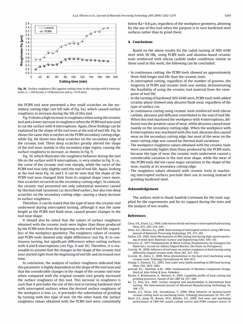
ig. 10. Surface roughness (Ra) against cutting time in the turning with 8 interrup-ions (vc = 150 m/min, f = 0.08 mm/rev and ap = 0.15 mm).
he PCBN tool nose presented a few small scratches on the sec-ndary cutting edge (see left side of Fig. 6a), which caused surfaceoughness to increase during the life of this tool.
Fig. 9 shows a high increase in roughness when using the ceramicool and a lower increase in roughness when the PCBN tool was usedo cut the surface with 4 interruptions. Again, these findings can bexplained by the shape of the tool nose at the end of tool life. Fig. 6chows the same thin scratches on the PCBN secondary cutting edge,hile Fig. 6d shows two deep scratches on the secondary edge of
he ceramic tool. These deep scratches greatly altered the shapef the tool nose, mainly in this secondary edge region, causing theurface roughness to increase, as shown in Fig. 9.
Fig. 10, which illustrates the roughness behavior during the toolife on the surface with 8 interruptions, is very similar to Fig. 9, i.e.,he curve of the ceramic tool rose sharply, while the curve of theCBN tool rose only slightly until the end of tool life. Again, lookingt the tool wear Fig. 6e and f, it can be seen that the shape of theCBN tool nose changed little from its original shape (once more,hin scratches occurred on the secondary cutting edge). In contrast,he ceramic tool presented not only substantial waviness causedy thermal load variations (as described earlier), but also two deepcratches on the secondary cutting edge, causing a sharp increasen surface roughness.
Therefore, it can be stated that the type of wear the ceramic toolnderwent during interrupted turning, although it was the sameeight as the PCBN tool flank wear, caused greater changes in theool nose shape.
It should also be noted that the values of surface roughnessbtained with the ceramic tools were higher than those producedy the PCBN tools from the beginning to the end of tool life, regard-ess of the workpiece geometry. The roughness values of ceramicnd PCBN tools showed only slight differences (see Fig. 8) in con-inuous turning, but significant differences when cutting surfacesith 4 and 8 interruptions (see Figs. 9 and 10). Therefore, it is rea-
onable to assume that the changes in the shape of the ceramic toolose started right from the beginning of tool life and increased overime.
In conclusion, the analysis of surface roughness indicated thathis parameter is highly dependent on the shape of the tool nose andhat the considerable changes in the shape of the ceramic tool nosehen compared with the original ceramic tool greatly increased
he surface roughness of this tool. This increase in roughness isuch that it precludes the use of this tool in turning hardened steel
ith interrupted surfaces when the desired surface roughness ofhe workpiece is low, i.e., it precludes the substitution of grindingy turning with this type of tool. On the other hand, the surfaceoughness values obtained with the PCBN tool were consistently
sing Technology 209 (2009) 5262–5270 5269
below Ra = 0.8 �m, regardless of the workpiece geometry, allowingfor the use of this tool when the purpose is to turn hardened steelsurfaces rather than to grind them.
4. Conclusions
Based on the above results for the radial turning of AISI 4340steel with 56 HRC using PCBN tools and alumina-based ceramictools reinforced with silicon carbide under conditions similar tothose used in this work, the following can be concluded:
- In continuous cutting, the PCBN tools showed an approximatelythree-fold longer tool life than the ceramic tools.
- In interrupted cutting, regardless of the number of grooves, thelongevity of PCBN and ceramic tools was similar, demonstratingthe feasibility of using the ceramic tool material from the view-point of tool life.
- In the turning of hardened AISI 4340 steel, PCBN tools with addedceramic phase showed only abrasive flank wear, regardless of thetype of surface cut.
- In continuous cutting using ceramic tools reinforced with siliconcarbide, abrasion and diffusion contributed to the end of tool life.When this tool machined the workpiece with 4 interruptions, dif-fusion was the greatest cause of wear, while abrasion caused wearmainly on the secondary cutting edge. When the workpiece with8 interruptions was machined with this tool, abrasion also causedwear on the secondary cutting edge, but most of the wear on themain cutting edge was caused by thermal load variations.
- The workpiece roughness values obtained with the ceramic toolswere consistently higher than those produced by the PCBN tools,because the type of wear the ceramic tools underwent caused aconsiderable variation in the tool nose shape, while the wear ofthe PCBN tools did not cause major variations in the shape of thenose, mainly at its secondary cutting edge.
- The roughness values obtained with ceramic tools in machin-ing interrupted surfaces preclude their use in turning instead ofgrinding hardened steel.
Acknowledgement
The authors wish to thank Sandvik Coromant for the tools sup-plied for the experiments and for its support during the tests andthe analysis of test results.
References
Chou, Y.K., Evans, C.J., 1999. Cubic boron nitride tool wear in interrupted hard turning.Wear 225–229, 234–245.
Diniz, A.E., Oliveira, A.J., 2008. Hard turning of interrupted surfaces using CBN tools.Journal of Materials Processing Technology 195, 275–281.
Farhat, Z.N., 2003. Wear Mechanisms of CBN cutting tool during high-speed machin-ing of mold steel. Materials Science and Engineering A361, 100–110.
Ferraresi, D., 1977. Fundamentals of Metal Cutting (Fundamentos da Usinagem dosMateriais), second ed. Editora Edgard Blucher, São Paulo (in Portuguese).
Grzesik, W., 2008. Influence of tool wear on surface roughness in hard turning usingdifferently shaped ceramic tools. Wear 265, 327–335.
Grzesik, W., Zalisz, Z., 2008. Wear phenomenon in the hard steel machining usingceramic tools. Tribology International 41, 802–812.
Huang, Y., Dawson, T.G., 2005. Tool crater wear depth modeling in CBN hard turning.Wear 258, 1455–1461.
Juvinall, R.C., Marshek, K.M., 1999. Fundamentals of Machine Component Design,third ed. John Wiley & Sons, Hoboken.
Klocke, F., Brinksmeier, E., Weinert, K., 2005. Capability profile of hard cutting andgrinding processes. Annals of the CIRP 54, 557–580.
Ko, T.J., Him, H.S., 2001. Surface integrity and machinability in intermittent hard
168–175.Kumar, A.S., Durai, A.R., Sornakumar, T., 2006. Wear behavior of alumina-based
ceramic cutting tools on machining steels. Tribology International 39, 191–197.More, A.S., Jiang, W., Brown, W.D., Malshe, A.P., 2006. Tool wear and machining
performance of CBN-TiN coated carbide inserts and PCBN compact inserts in

5 Proces
R
SS
270 A.J.d. Oliveira et al. / Journal of Materials
turning AISI 4340 hardened steel. Journal of Materials Processing Technology180, 253–262.
emadna, M., Rigal, J.F., 2006. Evolution during time of tool wear and cutting forces incase of hard turning with CBN inserts. Journal of Materials Processing Technology178, 67–75.
andvik Coromant, 2006. Main Catalogue. www.coromant.sandvik.com/.tephenson, D.A., Agapiou, J.S., 1996. Metal Cutting Theory and Practice, first ed.
Marcel Dekker, New York.
sing Technology 209 (2009) 5262–5270
Trent, E.M., Wright, P.K., 2000. Metal Cutting, fourth ed. Butterworth-Heinemann,Oxford.
Ueda, T., Huda, M.A., Yamada, K., Nakayama, K., 1999. Temperature measurement ofCBN tool in turning of high hardness steel. Annals of the CIRP 48, 63–66.
Yallese, M.A., Rigal, J.F., Chaoui, K., Boulanouar, L., 2005. The effect of cutting con-ditions on mixed ceramic and cubic boron nitride tool wear and on surfaceroughness during machining of X200Cr12 steel (60 HRC). Proceedings of Insti-tution of Mechanical: Part B: Engineering Manufacture 219, 35–55.