Embed Size (px)
Citation preview

Hardware and Wiring Manual
for the VersioBus II Interface System
Revision 1.30 © 2012 Soft Servo Systems, Inc.
HARDWARE & WIRING MANUAL FOR THE VERSIOBUS II INTERFACE SYSTEM
Warning / Important Notice / Safety Notes
_____________________________________________________________________________________
i
Warning
The product described herein has the potential – through misuse, inattention, or lack of understanding – to create
conditions that could result in personal injury, damage to equipment, or damage to the product(s) described herein.
Machinery in motion and high-power, high-current servo drives can be dangerous; potentially hazardous situations
such as runaway motors could result in death; burning or other serious personal injury to personnel; damage to
equipment or machinery; or economic loss if procedures aren’t followed properly. Soft Servo Systems, Inc. assumes
no liability for any personal injury, property damage, losses or claims arising from misapplication of its products. In
no event shall Soft Servo Systems, Inc. or its suppliers be liable to you or any other person for any incidental
collateral, special or consequential damages to machines or products, including without limitation, property damage,
damages for loss of profits, loss of customers, loss of goodwill, work stoppage, data loss, computer failure or
malfunction claims by any party other than you, or any and all similar damages or loss even if Soft Servo Systems,
Inc., its suppliers, or its agent has been advised of the possibility of such damages.
It is therefore necessary for any and all personnel involved in the installation, maintenance, or use of these products
to thoroughly read this manual and related manuals and understand their contents. Soft Servo Systems, Inc. stands
ready to answer any questions or clarify any confusion related to these products in as timely a manner as possible.
The selection and application of Soft Servo Systems, Inc.’s products remain the responsibility of the equipment
designer or end user. Soft Servo Systems, Inc. accepts no responsibility for the way its controls are incorporated
into a machine tool or factory automation setting. Any documentation and warnings provided by Soft Servo
Systems, Inc. must be promptly provided to any end users.
This document is based on information that was available at the time of publication. All efforts have been made to
ensure that this document is accurate and complete. However, due to the widely varying uses of this product, and
the variety of software and hardware configurations possible in connection with these uses, the information
contained in this manual does not purport to cover every possible situation, contingency or variation in hardware or
software configuration that could possibly arise in connection with the installation, maintenance, and use of the
products described herein. Soft Servo Systems, Inc. assumes no obligations of notice to holders of this document
with respect to changes subsequently made. Under no circumstances will Soft Servo Systems, Inc. be liable for any
damages or injuries resulting from any defect or omission in this manual.
Soft Servo Systems, Inc. makes no representation or warranty, expressed, implied, or statutory with respect to, and
assumes no responsibility for the accuracy, completeness, sufficiency, or usefulness of the information contained
herein. NO IMPLIED WARRANTIES OF MERCHANTABILITY OR FITNESS OF PURPOSE SHALL APPLY.
The DC-155 servo-related I/O and general I/O have different characteristics. Only
the servo-related input is sourcing. The servo-related output, the general inputs, and
the general outputs are sinking.
CAUTION !
HARDWARE & WIRING MANUAL FOR THE VERSIOBUS II INTERFACE SYSTEM
Warning / Important Notice / Safety Notes
_____________________________________________________________________________________
ii
Important Notice
The information contained in this manual is intended to be used only for the purposes agreed upon in the related
contract with Soft Servo Systems, Inc. All material contained herein is subject to restricted rights and restrictions
set forth in the contract between the parties.
These manuals contain confidential and proprietary information that is not to be shared with, nor distributed to, third
parties by any means without the prior express, written permission of Soft Servo Systems, Inc. No materials
contained herein are to be duplicated or reproduced in whole or in part without the express, written permission of
Soft Servo Systems, Inc.
Although every effort and precaution has been taken in preparing this manual, the information contained herein is
subject to change without notice. This is because Soft Servo Systems, Inc. is constantly striving to improve its
products. Soft Servo Systems, Inc. assumes no responsibility for errors or omissions.
All rights reserved. Any violations of contractual agreements pertaining to the materials herein will be prosecuted to
the full extent of the law.

HARDWARE & WIRING MANUAL FOR THE VERSIOBUS II INTERFACE SYSTEM
Warning / Important Notice / Safety Notes
_____________________________________________________________________________________
iii
VersioBus II Release Notes
Soft Servo Systems, Inc. is pleased to announce the immediate availability of VersioBus II, the next generation of
the VersioBus fiber-optic communication protocol originally developed by Soft Servo Systems. The new VersioBus
II protocol is a proprietary 5 Mbps real-time fiber-optic digital servo and I/O communication protocol that provides
enhanced reliability and security, and supports a 1 ms multi-axis (up to 16 axes) interpolation cycle.
The difference between the VersioBus and VersioBus II interface systems, from a customer's point of view, is just a
matter of using new part numbers for the VersioBus II hardware components. The appearance, hardware
specifications, connections, wiring and setup remain exactly the same. Each VersioBus hardware component has a
corresponding VersioBus II hardware component that uses the new VersioBus II communication protocol, as shown
in the following table:
Component Type VersioBus VersioBus II
VersioBus PCI Adapter Board FP-95 FP-105
VersioBus ISA Adapter Board FP-80 FP-85
VersioBus PC104 Adapter Board FP-104 FP-114
Servo Interface Module DC-150 DC-155
I/O Module IM-300 IM-305
When ordering a ServoWorks CNC or SMP product for the VersioBus II interface system, you will need to use
"V2P" or "V2I" as the suffix for the product part number ["V2P" and "V2I" replace the "VBP" and "VBI" suffixes
used for the older VersioBus interface system.] For instance, "3S-MCQ-V2I" indicates ServoWorks MC-Quad with
an FP-85 (ISA) adapter board and a DC-155 servo interface module. [The "P" in the suffix indicates a PCI adapter
board, the "I" indicates an ISA adapter board.]
The VersioBus and VersioBus II protocols are not compatible. In other words, VersioBus hardware components
(adapter boards, servo interface modules and I/O modules) cannot be included in the same network as VersioBus II
hardware components. Care must be taken to avoid mixing VersioBus and VersioBus II products in the same
system.
The same VersioBus fiber-optic cable works for both VersioBus and VersioBus II interface systems. The HW-100
handwheel and the breakout boxes (TB36A, TB36B and TB37BD) that were optional components in the VersioBus
interface system are also optional components in the VersioBus II interface system. These components do not use a
fiber-optic protocol, and can be used interchangeably with existing VersioBus interface systems and with any new
VersioBus II interface systems.
If you are using an existing VersioBus system, replacement VersioBus hardware components (FP-80s, FP-95s,
FP-104s, DC-150s and IM-300s) will be made available for one year, after which they will be discontinued.
Please contact [email protected] with any questions you may have regarding this new protocol.
HARDWARE & WIRING MANUAL FOR THE VERSIOBUS II INTERFACE SYSTEM
Warning / Important Notice / Safety Notes
_____________________________________________________________________________________
iv
Safety Notes
PC Location
Mounting Location
Operational Precautions
It is strongly recommended that you do not locate the PC inside the electric cabinet,
to minimize the possibility of problems due to electrical noise being introduced into
the PC motherboard (through air and/or poorly shielded wires such as keyboard,
mouse or handwheel cables). Such noise could affect the PCI or ISA bus data flow
within the PC, or possibly even the CPU/memory operations of the PC. In fact, it is
recommended that you locate the PC as far from the servo drives (the main source of
electrical noise) as practicality permits.
CAUTION !
Never use VersioBus II components in an area where those components could be
exposed to water (such as splashing), due to the risk of electric shock or fire.
CAUTION !
Never use VersioBus II components next to flammable items, or in a corrosive or
flammable atmosphere, due to the risk of electric shock or fire.
CAUTION !
The VersioBus II interface system is for incremental encoders only. Do not use the
VersioBus II interface system with absolute encoders.
CAUTION !

HARDWARE & WIRING MANUAL FOR THE VERSIOBUS II INTERFACE SYSTEM
Warning / Important Notice / Safety Notes
_____________________________________________________________________________________
v
Set all system parameters before operating any components in the VersioBus II
interface system. See the Reference Manual for ServoWorks CNC Parameters and
Functions, the ServoWorks S-100T Parameters Manual, or the Reference Manual for
SMP Parameters and Functions.
CAUTION !
Test the Emergency Stop before operating any components in the VersioBus II
interface system. Make sure the Emergency Stop can be applied at any time.
CAUTION !
Never open up any VersioBus II components, or touch the inside of any VersioBus II
component. Doing so may result in damage to the component, or could result in
electrical shock.
CAUTION !
Be sure no wiring is exposed before operating any components in the VersioBus II
interface system.
CAUTION !
Do not change the wiring while the power is on, due to the risk of electrical shock or
injury.
CAUTION !

HARDWARE & WIRING MANUAL FOR THE VERSIOBUS II INTERFACE SYSTEM
Contents
_____________________________________________________________________________________
vi
Table of Contents
Warning ............................................................................................................................................................................................ i Important Notice ............................................................................................................................................................................. ii VersioBus II Release Notes .......................................................................................................................................................... iii Safety Notes ................................................................................................................................................................................... iv
PC Location .............................................................................................................................................................iv Mounting Location ..................................................................................................................................................iv Operational Precautions ...........................................................................................................................................iv
Table of Contents .......................................................................................................................................................................... vi List of Tables.................................................................................................................................................................................. ix List of Figures ................................................................................................................................................................................ xi Chapter 1: VersioBus II Adapter Boards ................................................................................................................................... 1-1
1.1 Descriptions of VersioBus II Adapter Boards ................................................................................................ 1-1 1.2 VersioBus II Adapter Board Functional Specifications .................................................................................. 1-2 1.3 VersioBus II Adapter Board Schematics ........................................................................................................ 1-3
1.3.1 FP-85 Schematic ..................................................................................................................................... 1-3 1.3.2 FP-105 Schematic ................................................................................................................................... 1-4 1.3.3 FP-114 Schematic ................................................................................................................................... 1-5
1.4 VersioBus II Adapter Board Pin Assignments ................................................................................................ 1-6 1.4.1 Handwheel Header Block ....................................................................................................................... 1-6 1.4.2 Local I/O Header Block (J2 Header Block on the FP-85, the J3 Header Block on the FP-105 and the J2
Header Block on the FP-114) ........................................................................................................................... 1-7 1.5 Pin Assignments for Bracket Connectors to a VersioBus II Adapter Board ................................................... 1-8
1.5.1 Pin Assignments for a DB37F On-Board I/O Port Attached to a VersioBus II Adapter Board ..................... 1-8 1.5.2 Pin Assignments for a DB25F Handwheel Port Attached to a VersioBus II Adapter Board .................. 1-9
1.6 VersioBus II Adapter Board On-Board I/O Specifications, Internal Circuitry & Wiring Diagrams ............ 1-10 1.6.1 16-Point Inputs (IN00-IN15) ................................................................................................................. 1-10 1.6.2 16-Point Outputs (OUT00-OUT15) ...................................................................................................... 1-11 1.6.3 Single-Ended Handwheel Encoder Connection .................................................................................... 1-13
1.7 Comparison of VersioBus II Adapter Boards ............................................................................................... 1-15 Chapter 2: Servo Interface Modules .......................................................................................................................................... 2-1
2.1 DC-155 Description ........................................................................................................................................ 2-1 2.2 DC-155 Functional Specifications .................................................................................................................. 2-5 2.3 DC-155 Dipswitch Settings ............................................................................................................................ 2-7 2.4 DC-155 Pin Assignments ................................................................................................................................ 2-8
2.4.1 Axis Connector Pin Assignments (Axis 1-4 Connectors) ....................................................................... 2-8 2.4.2 General I/O Connector Pin Assignments – I/O Connector 1 ................................................................... 2-9 2.4.3 General I/O Connector Pin Assignments – I/O Connector 2 ................................................................. 2-10
2.5 DC-155 Specifications, Internal Circuitry & Wiring Diagrams .................................................................... 2-11 2.5.1 DC-155 Servo-Related Digital Inputs: FAULT, SS0-SS3 (Servo Status), HS0-HS3 (Home Switches),
PLS0-PLS3 and NLS0-NLS3 (Positive and Negative Limit Switches) ......................................................... 2-11 2.5.2 DC-155 Servo-Related Digital Outputs: SVON, RST, SC0-SC3 ......................................................... 2-13 2.5.3 DC-155 General I/O Connector Digital Inputs (DI00-DI15) ................................................................ 2-15 2.5.4 DC-155 General I/O Connector Digital Outputs (DO00-DO15) .......................................................... 2-16
2.6 DC-155 Schematic Servo Motor and Encoder Connections ......................................................................... 2-18 2.6.1 Axis Arrangement #1: Essential Servo Motor Connections in the VersioBus II System When the Servo
Amplifier Provides the Encoder Signals ........................................................................................................ 2-18 2.6.2 Axis Arrangement #2: Essential Servo Motor Connections in the VersioBus II System When the Signals
Come Directly From the Encoder .................................................................................................................. 2-19 2.6.3 Optional Servo Motor Connections ....................................................................................................... 2-20 2.6.4 Typical Connection Between a Differential Encoder and the DC-155 ................................................. 2-21
2.7 Cable Connections – DC-155 to Specific Servo Drives ............................................................................... 2-22 2.7.1 Recommended Direct Cable Connections Between the DC-155 Axis Connector & the YASKAWA
Sigma I (SGDA) Servo Drive (Incremental Encoder) ................................................................................... 2-23

HARDWARE & WIRING MANUAL FOR THE VERSIOBUS II INTERFACE SYSTEM
Contents
_____________________________________________________________________________________
vii
2.7.2 Recommended Direct Cable Connections Between the DC-155 Axis Connector & the YASKAWA
Sigma I (SGDB) Servo Drive (Incremental Encoder) .................................................................................... 2-24 2.7.3 Recommended Direct Cable Connections Between the DC-155 Axis Connector & the YASKAWA
Sigma II (SGDH) Servo Drive (Incremental Encoder) .................................................................................. 2-25 2.7.4 Recommended Direct Cable Connections Between the DC-155 Axis Connector & the Mitsubishi
MELSERVO-J2-A Servo Drive (Incremental Encoder) ................................................................................ 2-27 2.8 FPGA Hardware Shell Architecture ............................................................................................................. 2-29
2.8.1 FPGA Hardware Shell Architecture for AC and DC Motors ................................................................ 2-29 2.8.2 FPGA Hardware Shell Architecture for Linear Scales .......................................................................... 2-30
2.9 DC-125J Servo Interface Module ................................................................................................................. 2-31 2.9.1 DC-125J Diagrams ................................................................................................................................ 2-31 2.9.2 DC-125J Functional Specifications ....................................................................................................... 2-31 2.9.3 DC-125J ID Rotary Switch Setting ....................................................................................................... 2-33 2.9.4 DC-125J Pin Assignments .................................................................................................................... 2-34
2.9.4.1 Axis Connector Pin Assignments (Axis 1-4 Connectors) ............................................................. 2-34 2.9.4.2 General I/O Connector Pin Assignments – I/O Connector 1 ......................................................... 2-35 2.9.4.3 General I/O Connector Pin Assignments – I/O Connector 2 ......................................................... 2-36
2.9.5 DC-125J Internal Circuitry and Wiring Diagrams ................................................................................ 2-37 2.9.5.1 DC-125J IN1 (Servo-Related Digital Inputs) ................................................................................ 2-37 2.9.5.2 DC-125J OUT1 (Servo-Related Digital Outputs) ......................................................................... 2-37 2.9.5.3 DC-125J IN 2 (General Digital Inputs, Limit Switch Inputs, Home Switch Inputs) ..................... 2-38 2.9.5.4 DC-125J OUT2 (General Digital Outputs).................................................................................... 2-38 2.9.5.5 DC-125J IN3 (Encoder Input) ....................................................................................................... 2-39 2.9.5.6 DC-125J OUT4 (Analog Command Output) ................................................................................ 2-39
Chapter 3: I/O Modules ................................................................................................................................................................ 3-1 3.1 IM-305 Description ......................................................................................................................................... 3-1 3.2 IM-305 Functional Specifications ................................................................................................................... 3-2 3.3 IM-305 Dipswitch Settings ............................................................................................................................. 3-3 3.4 IM-305 Terminal Number Assignments ......................................................................................................... 3-4 3.5 Screw Terminals for IM-305 General Digital Inputs (GDI00-GDI31) ........................................................... 3-5 3.6 Screw Terminals for IM-305 General Digital Outputs (GDO00-GDO31) ..................................................... 3-9 3.7 IM-305 Specifications, Internal Circuitry & Wiring Diagrams .................................................................... 3-13
3.7.1 IM-305 General Digital Inputs (GDI00-GDI31) ................................................................................... 3-13 3.7.2 IM-305 General Digital Outputs (GDO00-GDO31) ............................................................................. 3-14
Chapter 4: Breakout Boxes ......................................................................................................................................................... 4-1 4.1 Breakout Boxes – Descriptions ....................................................................................................................... 4-1 4.2 TB36A / TB36B / TB37BD Functional Specifications .................................................................................. 4-1 4.3 TB36A Terminal Number Assignments ......................................................................................................... 4-2 4.4 TB36A Terminal Number Assignments for When TB36A Is Connected to the DC-155 Axis Connector ..... 4-2 4.5 TB36A Terminal Number Assignments for When TB36A Is Connected to the DC-155 I/O 1 Connector .... 4-3 4.6 TB36A Terminal Number Assignments for When TB36A Is Connected to the DC-155 I/O 2 Connector .... 4-3 4.7 TB36B Terminal Number Assignments.......................................................................................................... 4-4 4.8 TB36B Terminal Number Assignments for When the TB36B is Connected to the DC-155 Axis, I/O 1 & I/O 2
Connectors ............................................................................................................................................................ 4-5 4.9 TB36A & TB36B Terminal Pin Number Assignments .................................................................................. 4-6 4.10 TB37BD Terminal Number Assignments ..................................................................................................... 4-8 4.11 TB37BD Connector ...................................................................................................................................... 4-8 4.12 TB37BD Terminal Pin Number Assignments .............................................................................................. 4-9
Chapter 5: HW-200 Handwheel ................................................................................................................................................... 5-1 5.1 HW-200 Description ....................................................................................................................................... 5-1 5.2 HW-200 Functional Specifications ................................................................................................................. 5-1 5.3 HW-200 Pin Assignments for the 25-Pin DB Handwheel Connectors ........................................................... 5-4 5.4 HW-200 Wiring Diagrams .............................................................................................................................. 5-5
5.4.1 E-STOP / Handwheel Connections ......................................................................................................... 5-5 Chapter 6: HW-100 Handwheel ................................................................................................................................................... 6-1
6.1 HW-100 Description ....................................................................................................................................... 6-1

HARDWARE & WIRING MANUAL FOR THE VERSIOBUS II INTERFACE SYSTEM
Contents
_____________________________________________________________________________________
viii
6.2 HW-100 Functional Specifications ................................................................................................................. 6-1 6.3 HW-100 Pin Assignments for the 25-Pin DB Handwheel Connectors ........................................................... 6-4 6.4 HW-100 Specifications, Internal Circuitry & Wiring Diagrams .................................................................... 6-5
6.4.1 Coiled-Cable Specifications .................................................................................................................... 6-5 6.4.2 E-STOP Switch Specifications ................................................................................................................ 6-5 6.4.3 E-STOP / Handwheel Connections ......................................................................................................... 6-6
Chapter 7: DIN Rail Specifications ............................................................................................................................................. 7-1 Chapter 8: Wiring Examples for Connections .......................................................................................................................... 8-1
8.1 Typical Power Wiring Diagram ...................................................................................................................... 8-1 8.2 Wiring Example of an Analog Signal ............................................................................................................. 8-2 8.3 Wiring Examples of General Digital Bi-Directional Input ............................................................................. 8-3 8.4 Wiring Examples of Servo-Related Digital Output ........................................................................................ 8-4 8.5 Wiring Examples of Servo-Related Digital Input ........................................................................................... 8-6 8.6 Wiring Examples of General Input ................................................................................................................. 8-7 8.7 Wiring Example of General Output ................................................................................................................ 8-8 8.8 Wiring Example of a Ground Connection ...................................................................................................... 8-9

HARDWARE & WIRING MANUAL FOR THE VERSIOBUS II INTERFACE SYSTEM
Contents
_____________________________________________________________________________________
ix
List of Tables
Table 1-1: Functional Specifications of VersioBus II Adapter Boards ..................................................................... 1-2 Table 1-2: Pin Assignments for the Handwheel Header Block ................................................................................. 1-6 Table 1-3: Pin Assignments for the Local I/O Header Blocks on the FP-85, the FP-105 and the FP-114 ................ 1-7 Table 1-4: Pin Assignments for a TB37F Port Attached to an FP-85, an FP-105 or an FP-114 ................................ 1-8 Table 1-5: Pin Assignments for a TB25F Port Attached to a VersioBus II Adapter Board....................................... 1-9 Table 1-6: Specifications for IN00 – IN15 .............................................................................................................. 1-10 Table 1-7: Specifications for OUT00 – OUT15 ...................................................................................................... 1-12 Table 1-8: Comparison of VersioBus II Adapter Boards ........................................................................................ 1-15 Table 2-1: DC-155 Functional Specifications (1 of 2) .............................................................................................. 2-5 Table 2-2: DC-155 Functional Specifications (2 of 2) .............................................................................................. 2-6 Table 2-3: DC-155 Axis Connector Pin Assignments (Axis 1-4 Connectors) .......................................................... 2-8 Table 2-4: DC-155 General I/O Connector Pin Assignments (I/O Connector 1) ...................................................... 2-9 Table 2-5: DC-155 General I/O Connector Pin Assignments (I/O Connector 2) .................................................... 2-10 Table 2-6: Specifications for DC-155 Servo-Related Digital Inputs ....................................................................... 2-12 Table 2-7: Specifications for DC-155 Servo-Related Digital Outputs .................................................................... 2-14 Table 2-8: Specifications for DC-155 General I/O Connector Digital Inputs ......................................................... 2-15 Table 2-9: Specifications for DC-155 General I/O Connector Digital Outputs ....................................................... 2-17 Table 2-10: Recommended Direct Cable Connections to the YASKAWA Sigma I (SGDA) Servo Drive ............ 2-23 Table 2-11: Recommended Direct Cable Connections to the YASKAWA Sigma I (SGDB) Servo Drive ............. 2-24 Table 2-12: Recommended Direct Cable Connections to the YASKAWA Sigma II (SGDH) Servo Drive (1 of 2) 2-25 Table 2-13: Recommended Direct Cable Connections to the YASKAWA Sigma II (SGDH) Servo Drive (2 of 2) 2-26 Table 2-14: Recommended Direct Cable Connections to the Mitsubishi MELSERVO-J2-A Servo Drive (1 of 2) . 2-27 Table 2-15: Recommended Direct Cable Connections to the Mitsubishi MELSERVO-J2-A Servo Drive (2 of 2) . 2-28 Table 2-16: DC-125J Functional Specifications (1 of 2) ......................................................................................... 2-31 Table 2-17: DC-125J Functional Specifications (2 of 2) ......................................................................................... 2-32 Table 2-18: DC-125J ID Rotary Switch Setting ...................................................................................................... 2-33 Table 2-19: DC-125J Axis Connector Pin Assignments (Axis 1-4 Connectors) ..................................................... 2-34 Table 2-20: DC-125J General I/O Connector Pin Assignments (I/O Connector 1) ................................................. 2-35 Table 2-21: DC-125J General I/O Connector Pin Assignments (I/O Connector 2) ................................................. 2-36 Table 2-22: Specifications for DC-125J IN1 Inputs ................................................................................................ 2-37 Table 2-23: Specifications for DC-125J OUT1 Outputs ......................................................................................... 2-37 Table 2-24: Specifications for DC-125J IN2 Inputs ................................................................................................ 2-38 Table 2-25: Specifications for DC-125J OUT2 Outputs ......................................................................................... 2-38 Table 2-26: Specifications for DC-125J IN3 Inputs ................................................................................................ 2-39 Table 2-27: Specifications for DC-125J OUT4 Outputs ......................................................................................... 2-39 Table 3-1: IM-305 Functional Specifications ............................................................................................................ 3-2 Table 3-2: Screw Terminal Pin Assignments for General Digital Inputs (TERMINAL BLOCK 1 – IM-305)......... 3-5 Table 3-3: Screw Terminal Pin Assignments for General Digital Inputs (TERMINAL BLOCK 2 – IM-305)......... 3-6 Table 3-4: Screw Terminal Pin Assignments for General Digital Inputs (TERMINAL BLOCK 3 – IM-305)......... 3-7 Table 3-5: Screw Terminal Pin Assignments for General Digital Inputs (TERMINAL BLOCK 4 – IM-305)......... 3-8 Table 3-6: Screw Terminal Pin Assignments for General Digital Inputs (TERMINAL BLOCK 5 – IM-305)......... 3-9 Table 3-7: Screw Terminal Pin Assignments for General Digital Inputs (TERMINAL BLOCK 6 – IM-305)....... 3-10 Table 3-8: Screw Terminal Pin Assignments for General Digital Inputs (TERMINAL BLOCK 7 – IM-305)....... 3-11 Table 3-9: Screw Terminal Pin Assignments for General Digital Inputs (TERMINAL BLOCK 8 – IM-305)....... 3-12 Table 3-10: Specifications for IM-305 General Digital Inputs ................................................................................ 3-13 Table 3-11: Specifications for IM-305 General Digital Outputs ............................................................................. 3-15 Table 4-1: Functional Specifications for TB36A, TB36B and TB37BD Breakout Boxes ........................................ 4-1 Table 4-2: TB36A & TB36B Terminal Pin Number Assignments – SORTED BY TB36A TERMINAL # ............ 4-6 Table 4-3: TB36A & TB36B Terminal Pin Number Assignments – SORTED BY CONNECTOR PIN # .............. 4-7 Table 4-4: TB37BD Terminal Pin Number Assignments .......................................................................................... 4-9 Table 5-1: HW-200 Functional Specifications .......................................................................................................... 5-1 Figure 5-2: HW-200 Handwheel Schematic Diagram ............................................................................................... 5-2 Table 5-2: HW-200 Pin Assignments for the 25-Pin DB Handwheel Connectors .................................................... 5-4

HARDWARE & WIRING MANUAL FOR THE VERSIOBUS II INTERFACE SYSTEM
Contents
_____________________________________________________________________________________
x
Table 6-1: HW-100 Functional Specifications .......................................................................................................... 6-1 Table 6-2: HW-100 Pin Assignments for the 25-Pin DB Handwheel Connectors .................................................... 6-4 Table 6-3: Specifications for Coiled-Cable ............................................................................................................... 6-5 Table 6-4: Specifications for E-STOP Switch ........................................................................................................... 6-5
HARDWARE & WIRING MANUAL FOR THE VERSIOBUS II INTERFACE SYSTEM
Contents
_____________________________________________________________________________________
xi
List of Figures
Figure 1-1: Photos of Dual-Link VersioBus II Adapter Boards ................................................................................ 1-1 Figure 1-2: FP-85 VersioBus II Dual-Link Fiber-Optic Adapter Board .................................................................... 1-3 Figure 1-3: FP-105 VersioBus II Dual-Link Fiber-Optic Adapter Board .................................................................. 1-4 Figure 1-4: FP-114 VersioBus II Dual-Link Fiber-Optic Adapter Board .................................................................. 1-5 Figure 1-5: Internal Circuitry and Wiring for IN00 – IN15 ..................................................................................... 1-10 Figure 1-6: Internal Circuitry and Wiring for OUT00 – OUT15 ............................................................................. 1-11 Figure 1-7: Internal Circuitry and Wiring for a Single-Ended Handwheel Encoder Connection ............................ 1-13 Figure 1-8: Internal Circuitry and Wiring for a Differential Handwheel Encoder Connection ............................... 1-14 Figure 2-1: Photos of DC-155 Remote Servo Interface Module ............................................................................... 2-1 Figure 2-2: DC-155 VersioBus II Remote Servo Interface Schematic Front Diagram ............................................. 2-2 Figure 2-3: DC-155 VersioBus II Remote Servo Interface Schematic Bottom Diagram .......................................... 2-3 Figure 2-4: DC-155 Dimensions with Brackets in Millimeters ................................................................................. 2-4 Figure 2-5: Dipswitch ID Numbers for Daisy-Chained DC-155s ............................................................................. 2-7 Figure 2-6: Possible 2-Digit Dipswitch Configurations ............................................................................................ 2-7 Figure 2-7: Internal Circuitry and Wiring Diagram for DC-155 Servo-Related Digital Inputs ............................... 2-11 Figure 2-8: Internal Circuitry and Wiring Diagram for DC-155 Servo-Related Digital Outputs ............................ 2-13 Figure 2-9: Internal Circuitry and Wiring Diagram for DC-155 General I/O Connector Digital Inputs ................. 2-15 Figure 2-10: Internal Circuitry and Wiring Diagram for DC-155 General I/O Connector Digital Outputs ............ 2-16 Figure 2-11: Wiring Diagram for Essential Servo Motor Connections in the VersioBus II System When the Servo
Amplifier Provides the Encoder Signals .......................................................................................................... 2-18 Figure 2-12: Wiring Diagram for Essential Servo Motor Connections in the VersioBus II System When the Signals
Come Directly From the Encoder .................................................................................................................... 2-19 Figure 2-13: Wiring Diagram for Optional Servo Motor Connections .................................................................... 2-20 Figure 2-14: Wiring Diagram for a Typical Connection Between a Differential Encoder and the DC-155 ............ 2-21 Figure 2-15: Key to Recommended Direct Cable Connections Tables ................................................................... 2-22 Figure 2-16: Schematic Diagram: DC-155 FPGA Hardware Shell Architecture for AC and DC Motors .............. 2-29 Figure 2-17: Schematic Diagram: DC-155 FPGA Hardware Shell Architecture for Linear Scales ........................ 2-30 Figure 2-18: DC-125J Dimensions in Millimeters .................................................................................................. 2-31 Figure 2-19: Internal Circuitry and Wiring Diagram for DC-125J IN1 Inputs ........................................................ 2-37 Figure 2-20: Internal Circuitry and Wiring Diagram for DC-125J OUT1 Outputs ................................................. 2-37 Figure 2-21: Internal Circuitry and Wiring Diagram for DC-125J IN2 Inputs ........................................................ 2-38 Figure 2-22: Internal Circuitry and Wiring Diagram for DC-125J OUT2 Outputs ................................................. 2-38 Figure 2-23: Internal Circuitry and Wiring Diagram for DC-125J IN3 Inputs ........................................................ 2-39 Figure 2-19: Internal Circuitry and Wiring Diagram for DC-125J OUT4 Outputs ................................................. 2-39 Figure 3-1: Photos of the IM-305 General I/O Module ............................................................................................. 3-1 Figure 3-2: Dipswitch ID Numbers for Daisy-Chained IM-305s .............................................................................. 3-3 Figure 3-3: Possible 2-Digit Dipswitch Configurations ............................................................................................ 3-3 Figure 3-4: IM-305 VersioBus II General I/O Module Schematic Diagram ............................................................. 3-4 Figure 3-5: Screw Terminal Numbers for General Digital Inputs (TERMINAL BLOCK 1 – IM-305) ................... 3-5 Figure 3-6: Screw Terminal Numbers for General Digital Inputs (TERMINAL BLOCK 2 – IM-305) ................... 3-6 Figure 3-7: Screw Terminal Numbers for General Digital Inputs (TERMINAL BLOCK 3 – IM-305) ................... 3-7 Figure 3-8: Screw Terminal Numbers for General Digital Inputs (TERMINAL BLOCK 4 – IM-305) ................... 3-8 Figure 3-9: Screw Terminal Numbers for General Digital Inputs (TERMINAL BLOCK 5 – IM-305) ................... 3-9 Figure 3-10: Screw Terminal Numbers for General Digital Inputs (TERMINAL BLOCK 6 – IM-305) ............... 3-10 Figure 3-11: Screw Terminal Numbers for General Digital Inputs (TERMINAL BLOCK 7 – IM-305) ............... 3-11 Figure 3-12: Screw Terminal Numbers for General Digital Inputs (TERMINAL BLOCK 8 – IM-305) ............... 3-12 Figure 3-13: Internal Circuitry and Wiring Diagram for IM-305 General Digital Inputs........................................ 3-13 Figure 3-14: Internal Circuitry and Wiring Diagram for IM-305 General Digital Outputs ..................................... 3-14 Figure 4-1: Photos of TB36A, TB36B and TB37BD Breakout Boxes ...................................................................... 4-1 Figure 4-2: TB36A Breakout Box Terminal Number Assignments .......................................................................... 4-2 TERMINAL BLOCK 1 ............................................................................................................................................. 4-2 Figure 4-3: TB36A Terminal Number Assignments for When TB36A Is Connected to DC-155 Axis Connector ... 4-2

HARDWARE & WIRING MANUAL FOR THE VERSIOBUS II INTERFACE SYSTEM
Contents
_____________________________________________________________________________________
xii
Figure 4-4: TB36A Terminal Number Assignments for When TB36A Is Connected to the DC-155 I/O 1 Connector
........................................................................................................................................................................... 4-3 Figure 4-5: TB36A Terminal Number Assignments for When TB36A Is Connected to the DC-155 I/O 2 Connector
........................................................................................................................................................................... 4-3 Figure 4-6: TB36B Breakout Box Terminal Number Assignments .......................................................................... 4-4 Figure 4-7: TB36B Terminal Number Assignments ................................................................................................. 4-5 Figure 4-8: TB37BD Breakout Box Terminal Number Assignments ....................................................................... 4-8 Figure 5-1: Photo of HW-200 Handwheel ................................................................................................................. 5-1 Figure 5-3: Connection of the HW-200 Handwheel to a VersioBus II Adapter Board ............................................. 5-3 Figure 5-4: Wiring Diagram for E-STOP/Handwheel Connection............................................................................ 5-5 Figure 6-1: Photo of HW-100 Handwheel ................................................................................................................. 6-1 Figure 6-2: HW-100 Handwheel Schematic Diagram ............................................................................................... 6-2 Figure 6-3: Connection of the HW-100 Handwheel to a VersioBus II Adapter Board ............................................. 6-3 Figure 6-4: Wiring Diagram for E-STOP/Handwheel Connection............................................................................ 6-6 Figure 7-1: DIN Rail Dimensions .............................................................................................................................. 7-1 Figure 7-2: DIN Rail Mounting ................................................................................................................................. 7-1 Figure 8-1: Typical Power Wiring Diagram .............................................................................................................. 8-1 Figure 8-2: Wiring Example of an Analog Output Signal ......................................................................................... 8-2 Figure 8-3: Bi-Directional Signal Example #1 .......................................................................................................... 8-3 Figure 8-4: Wiring Example of a Servo-Related Output in Which the Servo Drive Uses Power Provided by the DC-
155 to Operate the Opto-Isolator ....................................................................................................................... 8-4 Figure 8-5: Wiring Example of a Servo-Related Output in Which the Servo Drive Uses Internal Power to Operate
the Opto-Isolator ................................................................................................................................................ 8-4 Figure 8-6: Wiring Example of a Servo-Related Output in Which the Servo Drive Does Not Use an Opto-Isolator 8-5 Figure 8-7: Wiring Example of a Servo-Related Output in Which the Servo Drive Employs DC-155 Output to Drive
Low Current Load Using +24V Provided .......................................................................................................... 8-5 Figure 8-8: Wiring Example of a Servo-Related Output in Which the Servo Drive Employs DC-155 Output to Drive
Low Current Load Without the +24V Provided ................................................................................................ 8-6 Figure 8-9: Wiring Example of a Pull-Down Switch or Open Collector Logic Signal ............................................. 8-6 Figure 8-10: Wiring Example of Normally Closed Limit Switches (Common Ground Connection) Connected to DC-
155 General Input .............................................................................................................................................. 8-7 Figure 8-11: Wiring Example of Normally Closed Limit Switches (Common “+” Supply Connection) Connected to
DC-155 General Input ....................................................................................................................................... 8-7 Figure 8-12: Wiring Example of a General Digital Output Signal for a DC-155 ...................................................... 8-8 Figure 8-13: Wiring Example of a Ground Connection for a DC-155 ...................................................................... 8-9

HARDWARE & WIRING MANUAL FOR THE VERSIOBUS II INTERFACE SYSTEM
Chapter 1: VersioBus II Adapter Boards
_____________________________________________________________________________________
1-1
Chapter 1: VersioBus II Adapter Boards
1.1 Descriptions of VersioBus II Adapter Boards
FP-85: A dual-link VersioBus™ II ISA adapter board for the host PC
FP-105: A dual-link VersioBus™ II PCI adapter board for the host PC
FP-114: A dual-link VersioBus™ II PC104 adapter board for the host PC
FP-85 FP-105 FP-114
Figure 1-1: Photos of Dual-Link VersioBus II Adapter Boards
HARDWARE & WIRING MANUAL FOR THE VERSIOBUS II INTERFACE SYSTEM
Chapter 1: VersioBus II Adapter Boards
_____________________________________________________________________________________
1-2
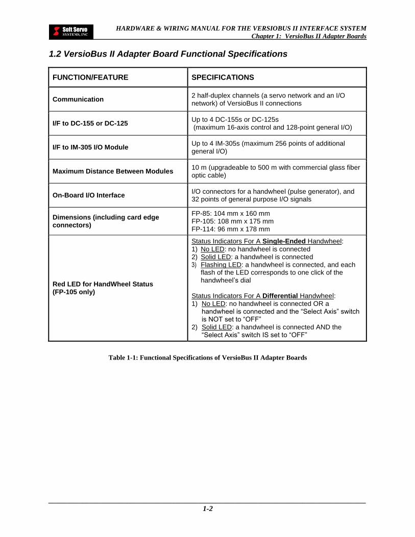
1.2 VersioBus II Adapter Board Functional Specifications
FUNCTION/FEATURE SPECIFICATIONS
Communication 2 half-duplex channels (a servo network and an I/O network) of VersioBus II connections
I/F to DC-155 or DC-125 Up to 4 DC-155s or DC-125s (maximum 16-axis control and 128-point general I/O)
I/F to IM-305 I/O Module Up to 4 IM-305s (maximum 256 points of additional general I/O)
Maximum Distance Between Modules 10 m (upgradeable to 500 m with commercial glass fiber optic cable)
On-Board I/O Interface I/O connectors for a handwheel (pulse generator), and 32 points of general purpose I/O signals
Dimensions (including card edge connectors)
FP-85: 104 mm x 160 mm FP-105: 108 mm x 175 mm FP-114: 96 mm x 178 mm
Red LED for HandWheel Status (FP-105 only)
Status Indicators For A Single-Ended Handwheel: 1) No LED: no handwheel is connected 2) Solid LED: a handwheel is connected 3) Flashing LED: a handwheel is connected, and each
flash of the LED corresponds to one click of the handwheel’s dial
Status Indicators For A Differential Handwheel: 1) No LED: no handwheel is connected OR a
handwheel is connected and the “Select Axis” switch is NOT set to “OFF”
2) Solid LED: a handwheel is connected AND the “Select Axis” switch IS set to “OFF”
Table 1-1: Functional Specifications of VersioBus II Adapter Boards

HARDWARE & WIRING MANUAL FOR THE VERSIOBUS II INTERFACE SYSTEM
Chapter 1: VersioBus II Adapter Boards
_____________________________________________________________________________________
1-3
1.3 VersioBus II Adapter Board Schematics
1.3.1 FP-85 Schematic
Figure 1-2: FP-85 VersioBus II Dual-Link Fiber-Optic Adapter Board
NOTE: Use a small ISA riser card to attach the FP-85 to the motherboard of the PC.
Align this slot with the matching projection of the ribbon cable plug connector of the flat cable (if using a TB37BD connector) J2 40-pin header block for general purpose I/O J1 26-pin header block for connection to an auxiliary encoder or handwheel Align this slot with the matching projection of the ribbon cable plug connector of the flat cable (if using an HW-100 handwheel)
Bracket plate
Transceiver that connects to the DC-155(s)
Transceiver that connects to the
IM-305(s) 134 mm
160 mm
104
mm
HARDWARE & WIRING MANUAL FOR THE VERSIOBUS II INTERFACE SYSTEM
Chapter 1: VersioBus II Adapter Boards
_____________________________________________________________________________________
1-4
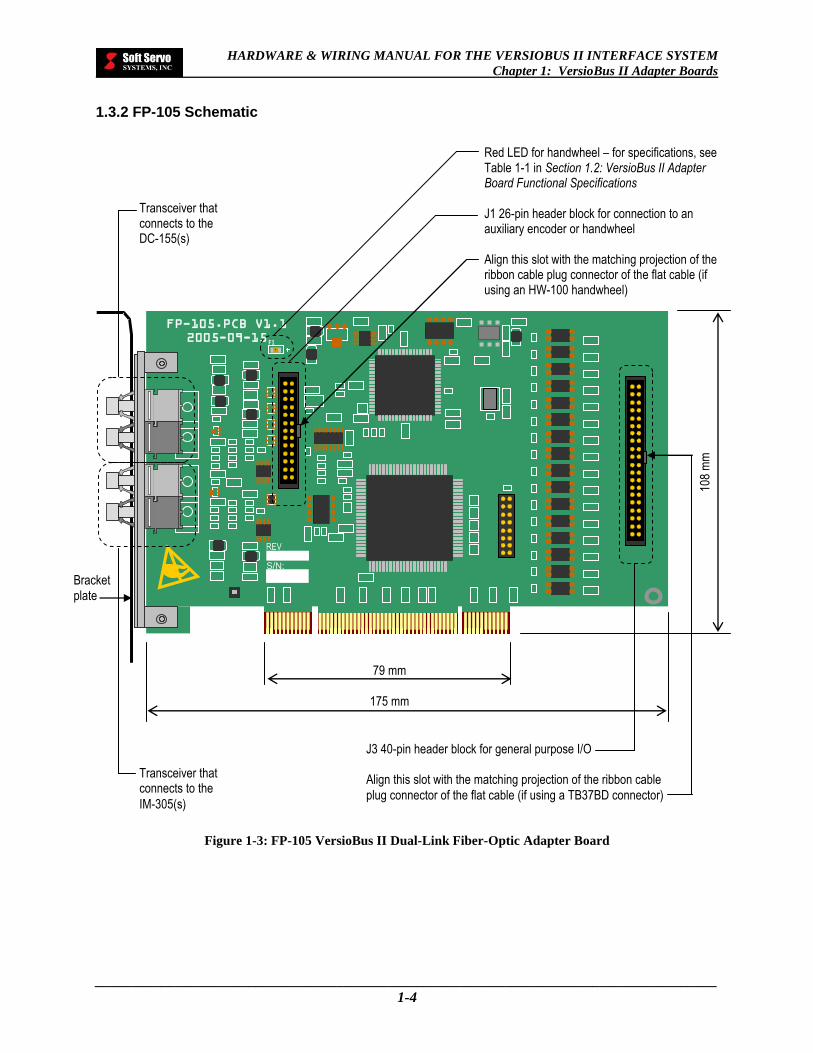
1.3.2 FP-105 Schematic
Figure 1-3: FP-105 VersioBus II Dual-Link Fiber-Optic Adapter Board
REV
S/N:
FP-105.PCB V1.1
2005-09-15 F1
Bracket plate
Transceiver that connects to the DC-155(s)
Transceiver that connects to the
IM-305(s)
Red LED for handwheel – for specifications, see Table 1-1 in Section 1.2: VersioBus II Adapter Board Functional Specifications J1 26-pin header block for connection to an auxiliary encoder or handwheel Align this slot with the matching projection of the ribbon cable plug connector of the flat cable (if using an HW-100 handwheel)
J3 40-pin header block for general purpose I/O Align this slot with the matching projection of the ribbon cable
plug connector of the flat cable (if using a TB37BD connector)
108
mm
79 mm
175 mm

HARDWARE & WIRING MANUAL FOR THE VERSIOBUS II INTERFACE SYSTEM
Chapter 1: VersioBus II Adapter Boards
_____________________________________________________________________________________
1-5
1.3.3 FP-114 Schematic
Figure 1-4: FP-114 VersioBus II Dual-Link Fiber-Optic Adapter Board
Transceiver that connects to the IM-305(s) Transceiver that connects to the
DC-155(s)
Align this slot with the matching projection of the ribbon cable plug connector of the flat cable (if using a TB37BD connector) J2 40-pin header block for general purpose I/O
Align this slot with the matching projection of the ribbon cable plug connector of the flat cable (if using an HW-100 handwheel) J1 26-pin header block for connection to an
auxiliary encoder or handwheel
96 m
m
178 mm
Alternate location of
transceivers

HARDWARE & WIRING MANUAL FOR THE VERSIOBUS II INTERFACE SYSTEM
Chapter 1: VersioBus II Adapter Boards
_____________________________________________________________________________________
1-6
1.4 VersioBus II Adapter Board Pin Assignments
1.4.1 Handwheel Header Block
This applies to the J1 Header Block on the FP-85, the J1 Header Block on the FP-105 and the J1 Header Block on the FP-114.
Table 1-2: Pin Assignments for the Handwheel Header Block
NOTES:
1) Pin 7 changes automatically in the internal circuitry of the VersioBus II adapter board according to whether
the attached handwheel has single-ended encoder output or differential encoder output.
2) The axis selector pins should be connected to one of the ground pins (pin 3 or pin 6) for the signal to be
registered. Refer to Figure 1-8.
3) For the HW-100 handwheel, this header block connects to a panel-mount, DB25F Handwheel and
Handwheel Emergency Stop connector. See pages 1-10 and 1-11 for handwheel connections and pin
definitions. The connection to the header block is described in Chapter 5: HW-100 Handwheel.
PIN NO. I/O SIGNAL PIN NO. I/O SIGNAL
1 I Encoder Signal A, Low Side 14 I Axis Y Selection2
2 I Encoder Signal A, High Side 15 I Axis Z Selection2
3 I Digital Ground 16 I Axis 4 Selection2
4 I Encoder Signal B, Low Side 17 I Axis 5 Selection2
5 I Encoder Signal B, High Side 18 O VCC (5V)
6 I Digital Ground 19 O VCC (5V)
7 I Encoder Input Select1 20 I NC
8 I X1 pulse multiplication 21 I NC
9 I X10 pulse multiplication 22 I NC
10 I X100 pulse multiplication 23 I NC
11 I NC 24 I NC
12 I LOGIC E-STOP 25 I NC
13 I Axis X Selection2 26 I NC
25 1
2 26

HARDWARE & WIRING MANUAL FOR THE VERSIOBUS II INTERFACE SYSTEM
Chapter 1: VersioBus II Adapter Boards
_____________________________________________________________________________________
1-7
1.4.2 Local I/O Header Block (J2 Header Block on the FP-85, the J3 Header Block on the FP-105 and the J2 Header Block on the FP-114)
Table 1-3: Pin Assignments for the Local I/O Header Blocks on the FP-85, the FP-105 and the FP-114
NOTES:
For a single power supply, jumper COM1_A_GND and COM2_B_GND together.
This header block connects to a panel-mount, DB37F I/O connector. Soft Servo Systems, Inc. offers the
TB37BD to provide a simple interface to I/O devices. Refer to Chapter 4: Breakout Boxes for information on
the TB37BD Connector.
PIN NO. SIGNAL PIN NO. SIGNAL
1 IN0 (Digital Input 0) 21 OUT1 (Digital Output 1)
2 IN1 (Digital Input 1) 22 OUT2 (Digital Output 2)
3 IN2 (Digital Input 2) 23 OUT3 (Digital Output 3)
4 IN3 (Digital Input 3) 24 OUT4 (Digital Output 4)
5 IN4 (Digital Input 4) 25 OUT5 (Digital Output 5)
6 IN5 (Digital Input 5) 26 OUT6 (Digital Output 6)
7 IN6 (Digital Input 6) 27 OUT7 (Digital Output 7)
8 IN7 (Digital Input 7) 28 NC
9 COM0_IN_GND (Common Ground 0) – for use with all digital inputs (pins 1-8, 10-17 )
29
COM2_B_GND (Common Ground 2) – for digital outputs 8 – 15 (pins 30-37)
10 IN8 (Digital Input 8) 30 OUT 8 (Digital Output 8)
11 IN9 (Digital Input 9) 31 OUT 9 (Digital Output 9)
12 IN10 (Digital Input 10) 32 OUT 10 (Digital Output 10)
13 IN11 (Digital Input 11) 33 OUT 11 (Digital Output 11)
14 IN12 (Digital Input 12) 34 OUT 12 (Digital Output 12)
15 IN13 (Digital Input 13) 35 OUT 13 (Digital Output 13)
16 IN14 (Digital Input 14) 36 OUT 14 (Digital Output 14)
17 IN15 (Digital Input 15) 37 OUT 15 (Digital Output 15)
18 NC 38 NC
19 COM1__A_GND (Common Ground 1) – for digital outputs 0 – 7 (pins 20-27)
39 NC
20 OUT0 (Digital Output 0) 40 NC
40
1
2
39

HARDWARE & WIRING MANUAL FOR THE VERSIOBUS II INTERFACE SYSTEM
Chapter 1: VersioBus II Adapter Boards
_____________________________________________________________________________________
1-8
1.5 Pin Assignments for Bracket Connectors to a VersioBus II Adapter Board
1.5.1 Pin Assignments for a DB37F On-Board I/O Port Attached to a VersioBus II Adapter Board
Soft Servo Systems offers receptacle hardware for easily creating an on-board I/O port in the host PC attached to the
VersioBus II adapter board that has been inserted in the host PC. This cable assembly consists of a DB-37 female
receptacle with a one foot long ribbon cable (with a PC bracket) that connects to the local I/O header block (the J2
header block on the FP-85, the J3 header block on the FP-105 and the J2 header block on the FP-114). [A breakout
box, such as the TB37BD, can be easily connected to this I/O port by using a ribbon jumper cable (with one to one
pin assignments).]
Table 1-4: Pin Assignments for a TB37F Port Attached to an FP-85, an FP-105 or an FP-114
PIN NO. SIGNAL PIN NO. SIGNAL
1 INB0 20 INB1
2 INB2 21 INB3
3 INB4 22 INB5
4 INB6 23 INB7
5 COM0_GND (for inputs) 24 INB8
6 INB9 25 INB10
7 INB11 26 INB12
8 INB13 27 INB14
9 INB15 28 NC
10 COM1_GND (for outputs 0 – 7, pins 11-14 & 29-32)
29 OUTB0
11 OUTB1 30 OUTB2
12 OUTB3 31 OUTB4
13 OUTB5 32 OUTB6
14 OUTB7 33 NC
15 COM2_GND (for outputs 8 – 15, pins 16-19 & 34-37)
34 OUTB8
16 OUTB9 35 OUTB10
17 OUTB11 36 OUTB12
18 OUTB13 37 OUTB14
19 OUTB15
Female 37-Pin DB Connector On the Ribbon Cable for
Connection to the Local I/O Header Block
20 37
1 19

HARDWARE & WIRING MANUAL FOR THE VERSIOBUS II INTERFACE SYSTEM
Chapter 1: VersioBus II Adapter Boards
_____________________________________________________________________________________
1-9
1.5.2 Pin Assignments for a DB25F Handwheel Port Attached to a VersioBus II Adapter Board
Table 1-5: Pin Assignments for a TB25F Port Attached to a VersioBus II Adapter Board
PIN NO. NAME SIGNAL
1 A_LO Encoder Signal A, Low Side
2 GND Digital Ground
3 B_HI Encoder Signal B, High Side
4 DIF_SEL Encoder Input Select
5 X10 X10
6 Not used
7 X-Axis Axis X
8 Z-Axis Axis Z
9 5-Axis Axis 5 (Optional)
10 Vcc Vcc (5V)
11 Not used
12 Not used
13 Not used
14 A_HI Encoder Signal A, High Side
15 B_LO Encoder Signal B, Low Side
16 GND Digital Ground
17 X1 X1
18 X100 X100
19 E-STOP LOGIC E-STOP
20 Y-Axis Axis Y
21 4-Axis Axis 4
22 Vcc Vcc (5V)
23 Not used
24 Not used
25 Not used
Female 25-Pin DB Connector On the Ribbon Cable for Connection to the J1 Header Block on the FP-85, the J1 Header Block on the FP-105 or the J1 Header Block on the FP-114
14 25
1 13
HARDWARE & WIRING MANUAL FOR THE VERSIOBUS II INTERFACE SYSTEM
Chapter 1: VersioBus II Adapter Boards
_____________________________________________________________________________________
1-10
1.6 VersioBus II Adapter Board On-Board I/O Specifications, Internal Circuitry & Wiring Diagrams
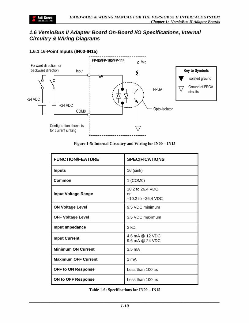
1.6.1 16-Point Inputs (IN00-IN15)
Figure 1-5: Internal Circuitry and Wiring for IN00 – IN15
FUNCTION/FEATURE SPECIFICATIONS
Inputs 16 (sink)
Common 1 (COM0)
Input Voltage Range 10.2 to 26.4 VDC or –10.2 to –26.4 VDC
ON Voltage Level 9.5 VDC minimum
OFF Voltage Level 3.5 VDC maximum
Input Impedance 3 k
Input Current 4.6 mA @ 12 VDC 9.6 mA @ 24 VDC
Minimum ON Current 3.5 mA
Maximum OFF Current 1 mA
OFF to ON Response Less than 100 s
ON to OFF Response Less than 100 s
Table 1-6: Specifications for IN00 – IN15
Key to Symbols
Isolated ground
Ground of FPGA
circuits FPGA
Input
Configuration shown is for current sinking
VCC
COM0
+24 VDC Opto-Isolator
FP-85/FP-105/FP-114
-24 VDC
Forward direction, or backward direction

HARDWARE & WIRING MANUAL FOR THE VERSIOBUS II INTERFACE SYSTEM
Chapter 1: VersioBus II Adapter Boards
_____________________________________________________________________________________
1-11
1.6.2 16-Point Outputs (OUT00-OUT15)
Figure 1-6: Internal Circuitry and Wiring for OUT00 – OUT15
Key to Symbols
Isolated ground
Ground of FPGA circuits
NOTE: If the load is a solenoid or a coil of an electromagnetic / mechanical relay, a high-speed fly-back diode must be installed across the load with the cathode end connected to VIN.
Load (DC Coil Relay)
Output
High-Speed Fly-Back Diode
VIN
VCC
COM1_A_GND or
COM2_B_GND
Output
12-24 VDC
Opto-Isolator
FP-85/FP-105/FP-114
FPGA
Load
HARDWARE & WIRING MANUAL FOR THE VERSIOBUS II INTERFACE SYSTEM
Chapter 1: VersioBus II Adapter Boards
_____________________________________________________________________________________
1-12
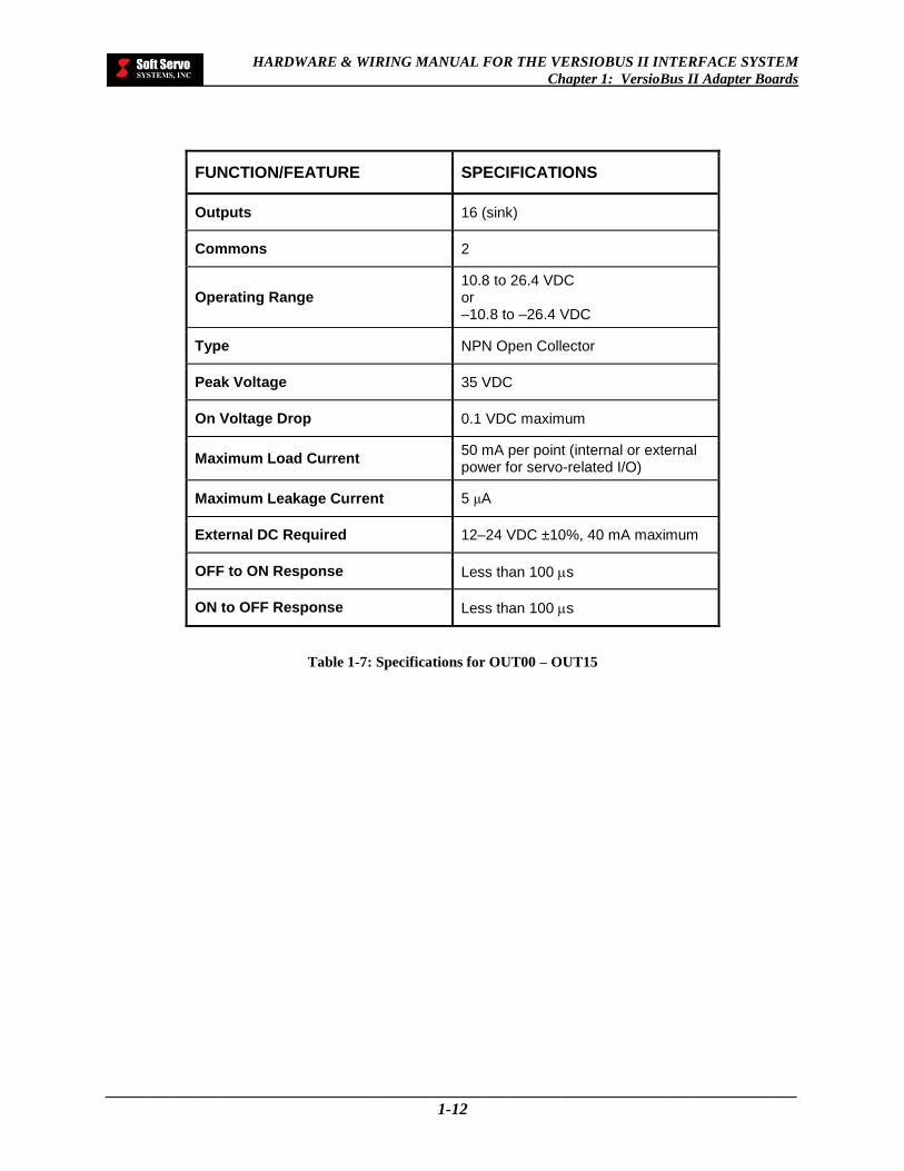
FUNCTION/FEATURE SPECIFICATIONS
Outputs 16 (sink)
Commons 2
Operating Range 10.8 to 26.4 VDC or –10.8 to –26.4 VDC
Type NPN Open Collector
Peak Voltage 35 VDC
On Voltage Drop 0.1 VDC maximum
Maximum Load Current 50 mA per point (internal or external power for servo-related I/O)
Maximum Leakage Current 5 μA
External DC Required 12–24 VDC ±10%, 40 mA maximum
OFF to ON Response Less than 100 s
ON to OFF Response Less than 100 s
Table 1-7: Specifications for OUT00 – OUT15

HARDWARE & WIRING MANUAL FOR THE VERSIOBUS II INTERFACE SYSTEM
Chapter 1: VersioBus II Adapter Boards
_____________________________________________________________________________________
1-13
1.6.3 Single-Ended Handwheel Encoder Connection
Figure 1-7: Internal Circuitry and Wiring for a Single-Ended Handwheel Encoder Connection
CONNECT JUMPER WIRES AS FOLLOWS: Connect Pin No. 7 to Pin No. 1 and Pin No. 4 via jumper
wires.
Single-Ended Encoder
Vcc Pin No. 19 or Pin No. 18
GND Pin No. 3 or Pin No. 6
Pin No. 2
Pin No. 5
A
B
Pin No. 8
X1
Pin No. 9
X10
Pin No. 10 X100
GND Pin No. 6 or Pin No. 3
Pin No. 13 X
Pin No. 14 Y
Pin No. 15 Z
Pin No. 16 4
GND Pin No. 6 or Pin No. 3
Pin No. 17 5
NOTE: Pin numbers refer to the pin assignments for the J1 header block on the FP-85, the J1 header block on the FP-105 or the J1 header block
on the FP-114.
optional

HARDWARE & WIRING MANUAL FOR THE VERSIOBUS II INTERFACE SYSTEM
Chapter 1: VersioBus II Adapter Boards
_____________________________________________________________________________________
1-14
1.6.4 Differential Handwheel Encoder Connection
Figure 1-8: Internal Circuitry and Wiring for a Differential Handwheel Encoder Connection
NOTE: Pin numbers refer to the pin assignments for the J1 header block on the FP-85, the J1 header block on the FP-105 or the J1 header block on the
FP-114.
optional
Pin No. 8 X1
Pin No. 9
X10
Pin No. 10
X100
GND Pin No. 6 or Pin No. 3
Pin No. 13 X
Pin No. 14 Y
Pin No. 15 Z
Pin No. 16 4
GND Pin No. 6 or Pin No. 3
Pin No. 17 5
Differential
Encoder
Vcc Pin No. 19 or Pin No. 18
GND Pin No. 3 or Pin No. 6
Pin No. 2
Pin No. 5
A
B
Pin No. 1
Pin No. 4
__
A
__
B
A_HI
B_HI
A_LO
B_LO

HARDWARE & WIRING MANUAL FOR THE VERSIOBUS II INTERFACE SYSTEM
Chapter 1: VersioBus II Adapter Boards
_____________________________________________________________________________________
1-15
1.7 Comparison of VersioBus II Adapter Boards
FUNCTION/ FEATURE
FP-85 FP-105 FP-114
Photo
Dimensions 104 mm x 160 mm 108 mm x 175 mm 96 mm x 178 mm
Connector ISA card edge
connector PCI card edge
connector PC104 stacking
connector
Local I/O header block
J2 header block J3 header block J2 header block
LED None Red LED for handwheel
status (see specifications)
None
Table 1-8: Comparison of VersioBus II Adapter Boards

HARDWARE & WIRING MANUAL FOR THE VERSIOBUS II INTERFACE SYSTEM
Chapter 2: Servo Interface Modules
_____________________________________________________________________________________
2-1
Chapter 2: Servo Interface Modules
The DC-155 is a VersioBus II servo interface module that interfaces with up to four servo axes and has 16 input bits
and 16 output bits.
NOTE: The DC-155 has been discontinued and replaced by the DC-125J servo interface module. Please see Section
2.9: DC-125J for more information on the DC-125J servo interface module.
2.1 DC-155 Description
DC-155: Four-axis servo drive & I/O interface module for incremental encoders
FRONT BOTTOM
Figure 2-1: Photos of DC-155 Remote Servo Interface Module

HARDWARE & WIRING MANUAL FOR THE VERSIOBUS II INTERFACE SYSTEM
Chapter 2: Servo Interface Modules
_____________________________________________________________________________________
2-2
Figure 2-2: DC-155 VersioBus II Remote Servo Interface Schematic Front Diagram
Battery backup for an absolute encoder (NOT USED) 24 VDC power supply screw terminal: connects to power supply cable
Power grounding point
SERVO INTERFACE
AX
IS 1
AX
IS 2
POWER
SOFT SERVO
SYSTEMS
ACTIVE READY
DC-155
24
V D
C
B
AT
+
–
+
–
AX
IS 3
AX
IS 4
I/O
1
I/O
2
185
mm
75 mm
HARDWARE & WIRING MANUAL FOR THE VERSIOBUS II INTERFACE SYSTEM
Chapter 2: Servo Interface Modules
_____________________________________________________________________________________
2-3
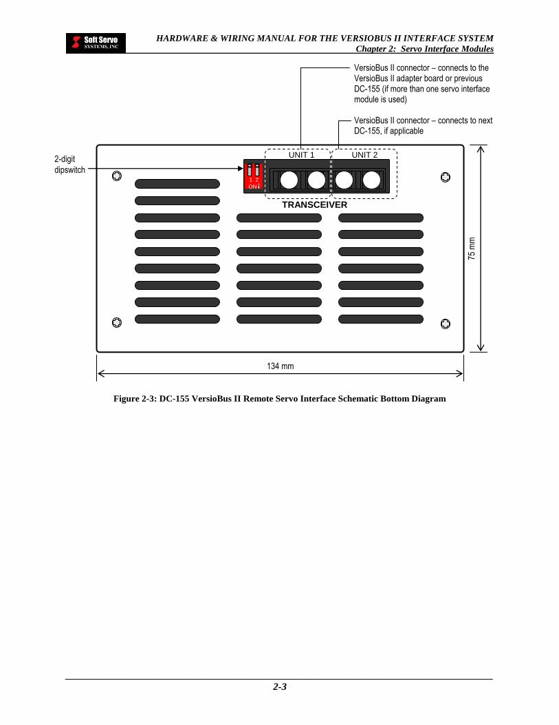
Figure 2-3: DC-155 VersioBus II Remote Servo Interface Schematic Bottom Diagram
2-digit
dipswitch
TRANSCEIVER
UNIT 1 UNIT 2
ON
1 2
VersioBus II connector – connects to the VersioBus II adapter board or previous DC-155 (if more than one servo interface module is used) VersioBus II connector – connects to next DC-155, if applicable
75 m
m
134 mm
HARDWARE & WIRING MANUAL FOR THE VERSIOBUS II INTERFACE SYSTEM
Chapter 2: Servo Interface Modules
_____________________________________________________________________________________
2-4
A
A
134
7
5
16
11 53 11
AXIS1
AXIS2
AXIS3
AXIS4
I/O1
I/O2
POWER
READYACTIVE
DC-150
16
185217
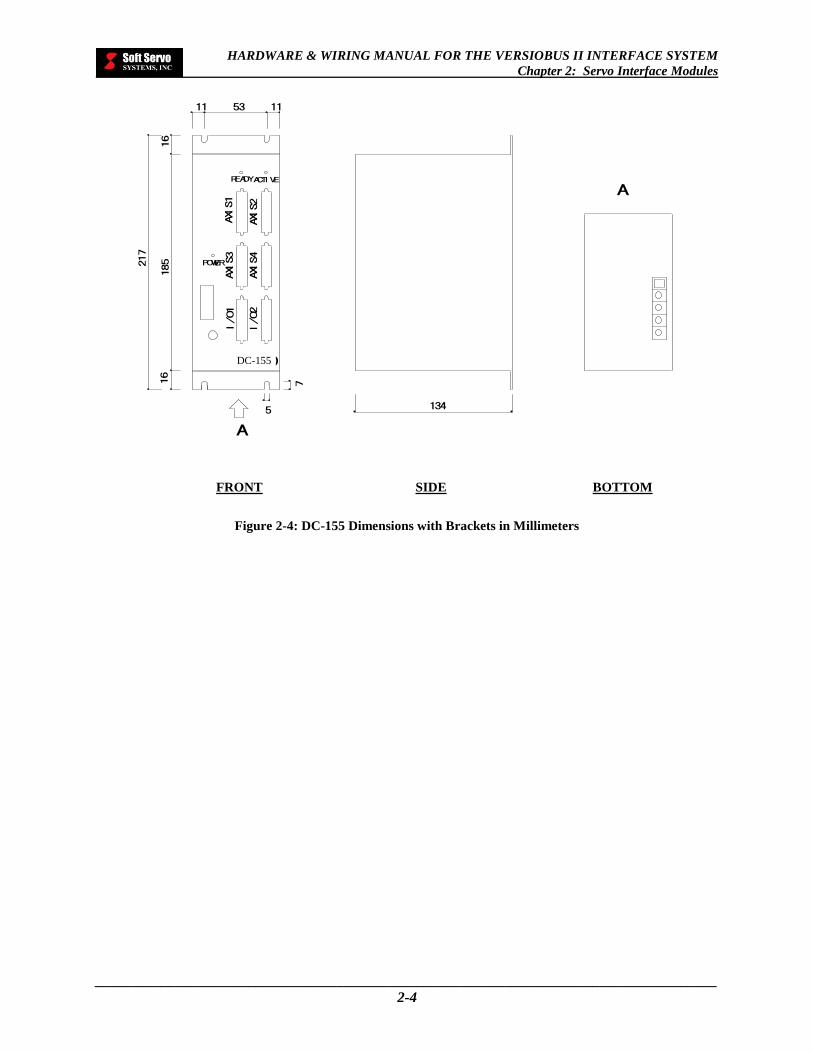
FRONT SIDE BOTTOM
Figure 2-4: DC-155 Dimensions with Brackets in Millimeters
DC-155

HARDWARE & WIRING MANUAL FOR THE VERSIOBUS II INTERFACE SYSTEM
Chapter 2: Servo Interface Modules
_____________________________________________________________________________________
2-5
2.2 DC-155 Functional Specifications
FUNCTION/FEATURE SPECIFICATIONS
Communications VersioBus II (a proprietary 5 Mbps real-time fiber-optic communication protocol) connections
Servo Axes 4 axes
Daisy Chainable (Scalable) Up to 4 DC-155s (maximum 16-axis control)
Connectors
6 × 36 pin IEEE 1284 MDR connector (4 × AXIS, 2 × I/O) Recommended connector and shell:
3M™ 10136-3000VE [Mini D Ribbon (MDR) Connectors, Wiremount Plugs & Accessories, Solder Plug Connector, Non-RoHS Compliant]
3M™ 10336-52F0-008 [Mini D Ribbon (MDR) Connectors, Plastic Solder Plug Junction Shell, Non Shielded]
Mounting Brackets and 4 M4 size screws (included with each DC-155)
Servo Types DC and AC servo motors
Encoder Type Incremental encoders
Maximum Frequency of Encoder Pulses 5 MHz
Input Power 24 VDC ±15%, maximum load current 800 mA
Output Power for Servo-Related I/O 24 VDC ±15%, maximum total load current 250 mA
Output Power for Encoder(s) 5 VDC ±15%, isolated, maximum load current 1000 mA/unit
Dimensions 185 mm (height excluding brackets) x 75 mm x 134 mm deep (height including brackets is 217 mm)
Analog Outputs 4 channels, 16 bits, ±10V, ±2%
Digital I/O
Servo commands and status: 11 points
Limit and home switches: 12 points (3 dedicated inputs per axis)
General uncommitted digital I/O: 16/16 points (generally connected with breakout terminal box TB36A or TB36B)
Table 2-1: DC-155 Functional Specifications (1 of 2)

HARDWARE & WIRING MANUAL FOR THE VERSIOBUS II INTERFACE SYSTEM
Chapter 2: Servo Interface Modules
_____________________________________________________________________________________
2-6
FUNCTION/FEATURE SPECIFICATIONS
Programmable Servo types, encoder types, I/O setting
Voltage Endurance 500 VDC for 1 minute (between input/output and frame ground)
Insulation Resistance 50 MΩ or more at 500 VDC (between input/output and frame ground)
Ambient Operating Temperature 0 to 55° C
Ambient Storage Temperature -25° to 70° C
Ambient Humidity 20% to 80% RH, no condensation
Cooling System Passive air cooling
Table 2-2: DC-155 Functional Specifications (2 of 2)

HARDWARE & WIRING MANUAL FOR THE VERSIOBUS II INTERFACE SYSTEM
Chapter 2: Servo Interface Modules
_____________________________________________________________________________________
2-7
2.3 DC-155 Dipswitch Settings
If you are using more than one DC-155, you must give each DC-155 a unique identification number. Identify the
first DC-155 as “1,” the second DC-155 as “2,” the third DC-155 as “3,” and so forth. The first DC-155 is the one
directly connected to the FP-85, FP-105 or FP-114. The second DC-155 is the next DC-155 in the daisy chain, and
so on.
NOTE: It’s very important that you correctly identify your DC-155s with the proper dipswitch identification
numbers:
Figure 2-5: Dipswitch ID Numbers for Daisy-Chained DC-155s
You must specify the identification number on a DC-155 by flipping the switches on the 2-digit dipswitch on the
DC-155. The following figure shows the configurations of switch locations, which correspond to identification
numbers 1 through 4 – use these as your guide.
[NOTE: For single DC-155 usage, the dipswitch ID number has to be set to 0, which is the factory default.]
Figure 2-6: Possible 2-Digit Dipswitch Configurations
This configuration sets the dipswitch ID# to 0.
This configuration sets the dipswitch ID# to 1.
This configuration sets the dipswitch ID# to 2.
This configuration sets the dipswitch ID# to 3.
I 2 ON
I 2 ON I 2 ON
I 2 ON
U3
U4
U8
U6
VersioBus II Adapter Board
DC-155 #2 DC-155 #3 DC-155 #1 DC-155 #4
Dipswitch ID #: 1
Dipswitch ID #: 2
Dipswitch ID #: 0
Dipswitch ID #: 3
Soft Servo Systems’ ServoWorks CNC and SMP applications use these DC-155 numbers to reference DC-155s.

HARDWARE & WIRING MANUAL FOR THE VERSIOBUS II INTERFACE SYSTEM
Chapter 2: Servo Interface Modules
_____________________________________________________________________________________
2-8
2.4 DC-155 Pin Assignments
2.4.1 Axis Connector Pin Assignments (Axis 1-4 Connectors)
PIN NO. NAME I/O SERVO FUNCTION
1
2 SS3 I Servo Status 3
3 SS1 I Servo Status 1
4 FAULT I Amp Fault
5 SC3 O Servo Command 3
6 SC1 O Servo Command 1
7 RST O Amp Reset (Alarm Reset)
8 GND Isolated 24V Return
9 VOUT O Isolated 24 VDC Output For Servo-Related I/O
10
11
12 +5V O 5 VDC for Encoders, 1000 mA/unit Maximum, Isolated
13
14 E_Z_H I Encoder Signal Z, High Side
15 E_B_H I Encoder Signal B, High Side
16 E_A_H I Encoder Signal A, High Side
17
18 A_OUT O Analog Command
19 AGND Analog Ground
20 GND Isolated 24V Return
21 SS2 I Servo Status 2
22 SS0 I Servo Status 0
23 GND Isolated 24V Return
24 SC2 O Servo Command 2
25 SC0 O Servo Command 0
26 SVON O Amp Enable (Servo On)
27 GND Isolated 24V Return
28
29
30
31
32 E_Z_L I Encoder Signal Z, Low Side
33 E_B_L I Encoder Signal B, Low Side
34 E_A_L I Encoder Signal A, Low Side
35 SG Signal Ground
36 AGND Analog Ground
Table 2-3: DC-155 Axis Connector Pin Assignments (Axis 1-4 Connectors)

HARDWARE & WIRING MANUAL FOR THE VERSIOBUS II INTERFACE SYSTEM
Chapter 2: Servo Interface Modules
_____________________________________________________________________________________
2-9
2.4.2 General I/O Connector Pin Assignments – I/O Connector 1
PIN NO. NAME I/O SERVO AND I/O FUNCTION
1 COM1 Common 1 (Ground for digital outputs)
2 DO6 O Digital Output 6
3 DO4 O Digital Output 4
4 DO3 O Digital Output 3
5 DO1 O Digital Output 1
6 COM1 Common 1 (Ground for digital outputs)
7
8
9
10 DI7 I Digital Input 7
11 DI5 I Digital Input 5
12 DI3 I Digital Input 3
13 DI1 I Digital Input 1
14 COM0 Common 0 (Ground for digital inputs)
15 NLS1 I Negative Limit Switch 1
16 GND 24V Return (isolated digital ground common for servo-related inputs such as limit switches & home switches)
17 NLS0 I Negative Limit Switch 0
18 GND 24V Return (isolated digital ground common for servo-related inputs such as limit switches & home switches)
19 COM1 Common 1 (Ground for digital outputs)
20 DO7 O Digital Output 7
21 DO5 O Digital Output 5
22 COM1 Common 1 (Ground for digital outputs)
23 DO2 O Digital Output 2
24 DO0 O Digital Output 0
25 COM1 Common 1 (Ground for digital outputs)
26 AGND I Analog Ground
27 AGND I Analog Ground
28 COM0 Common 0 (Ground for digital inputs)
29 DI6 I Digital Input 6
30 DI4 I Digital Input 4
31 DI2 I Digital Input 2
32 DI0 I Digital Input 0
33 PLS1 I Positive Limit Switch 1
34 HS1 I Home Switch 1
35 PLS0 I Positive Limit Switch 0
36 HS0 I Home Switch 0
Table 2-4: DC-155 General I/O Connector Pin Assignments (I/O Connector 1)

HARDWARE & WIRING MANUAL FOR THE VERSIOBUS II INTERFACE SYSTEM
Chapter 2: Servo Interface Modules
_____________________________________________________________________________________
2-10
2.4.3 General I/O Connector Pin Assignments – I/O Connector 2
PIN NO. NAME I/O SERVO AND I/O FUNCTION
1 COM2 Common 2 (Ground for digital outputs)
2 DO14 O Digital Output 14
3 DO12 O Digital Output 12
4 DO11 O Digital Output 11
5 DO9 O Digital Output 9
6 COM2 Common 2 (Ground for digital outputs)
7
8
9
10 DI15 I Digital Input 15
11 DI13 I Digital Input 13
12 DI11 I Digital Input 11
13 DI9 I Digital Input 9
14 COM0 Common 0 (Ground for digital inputs)
15 NLS3 I Negative Limit Switch 3
16 GND 24V Return (isolated digital ground common for servo-related inputs such as limit switches & home switches)
17 NLS2 I Negative Limit Switch 2
18 GND 24V Return (isolated digital ground common for servo-related inputs such as limit switches & home switches)
19 COM2 Common 2 (Ground for digital outputs)
20 DO15 O Digital Output 15
21 DO13 O Digital Output 13
22 COM2 Common 2 (Ground for digital outputs)
23 DO10 O Digital Output 10
24 DO8 O Digital Output 8
25 COM2 Common 2 (Ground for digital outputs)
26 AGND I Analog Ground
27 AGND I Analog Ground
28 COM0 Common 0 (Ground for digital inputs)
29 DI14 I Digital Input 14
30 DI12 I Digital Input 12
31 DI10 I Digital Input 10
32 DI8 I Digital Input 8
33 PLS3 I Positive Limit Switch 3
34 HS3 I Home Switch 3
35 PLS2 I Positive Limit Switch 2
36 HS2 I Home Switch 2
Table 2-5: DC-155 General I/O Connector Pin Assignments (I/O Connector 2)
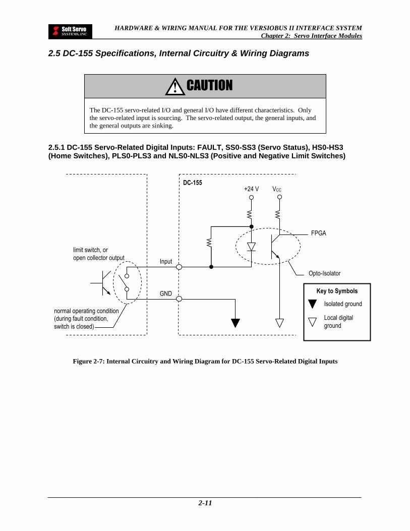
HARDWARE & WIRING MANUAL FOR THE VERSIOBUS II INTERFACE SYSTEM
Chapter 2: Servo Interface Modules
_____________________________________________________________________________________
2-11
2.5 DC-155 Specifications, Internal Circuitry & Wiring Diagrams
2.5.1 DC-155 Servo-Related Digital Inputs: FAULT, SS0-SS3 (Servo Status), HS0-HS3 (Home Switches), PLS0-PLS3 and NLS0-NLS3 (Positive and Negative Limit Switches)
Figure 2-7: Internal Circuitry and Wiring Diagram for DC-155 Servo-Related Digital Inputs
VCC +24 V
GND
Input
limit switch, or
open collector output
FPGA
DC-155
Opto-Isolator
Key to Symbols
Isolated ground
Local digital
ground
normal operating condition (during fault condition,
switch is closed)
The DC-155 servo-related I/O and general I/O have different characteristics. Only
the servo-related input is sourcing. The servo-related output, the general inputs, and
the general outputs are sinking.
CAUTION !

HARDWARE & WIRING MANUAL FOR THE VERSIOBUS II INTERFACE SYSTEM
Chapter 2: Servo Interface Modules
_____________________________________________________________________________________
2-12
FUNCTION/FEATURE SPECIFICATIONS
Inputs Per Axis 8 (Source)
ON State Terminal Voltage 0 VDC
OFF State Terminal Voltage 24 VDC ±10% (internally provided)
ON State Sourcing Current 3 mA minimum
OFF State Sourcing Current 1 mA maximum
OFF to ON Response Less than 100 s
ON to OFF Response Less than 100 s
Maximum State Sourcing 4 mA per point
Table 2-6: Specifications for DC-155 Servo-Related Digital Inputs
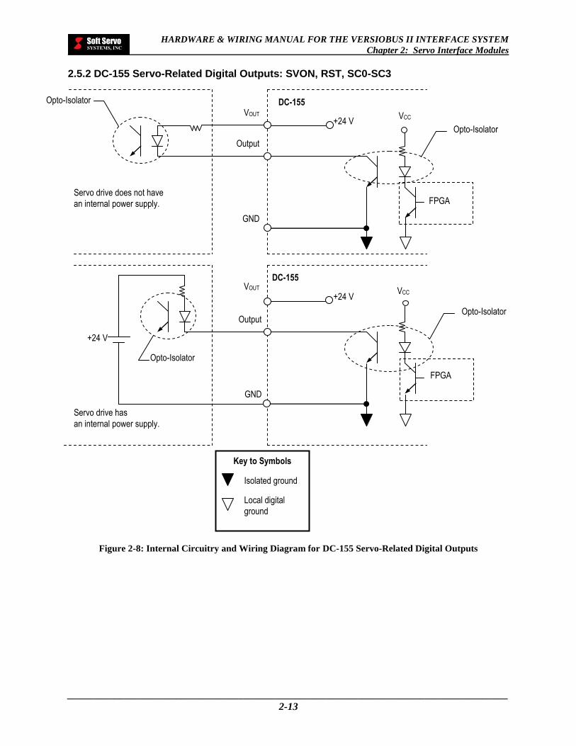
HARDWARE & WIRING MANUAL FOR THE VERSIOBUS II INTERFACE SYSTEM
Chapter 2: Servo Interface Modules
_____________________________________________________________________________________
2-13
2.5.2 DC-155 Servo-Related Digital Outputs: SVON, RST, SC0-SC3
Figure 2-8: Internal Circuitry and Wiring Diagram for DC-155 Servo-Related Digital Outputs
Key to Symbols
Isolated ground
Local digital
ground
VCC +24 V
GND
Output
VOUT
DC-155
Servo drive does not have
an internal power supply.
Opto-Isolator
Opto-Isolator
FPGA
VCC +24 V
GND
Output
VOUT
DC-155
Servo drive has
an internal power supply.
+24 V
Opto-Isolator
Opto-Isolator
FPGA

HARDWARE & WIRING MANUAL FOR THE VERSIOBUS II INTERFACE SYSTEM
Chapter 2: Servo Interface Modules
_____________________________________________________________________________________
2-14
FUNCTION/FEATURE SPECIFICATIONS
Outputs Per Axis 6 (sink)
Operating Range 10.8 to 26.4 VDC or –10.8 to –26.4 VDC
Type NPN Open Collector
Peak Voltage 35 VDC
Maximum Load Current 50 mA per point (internal or external power for servo-related I/O)
Maximum Leakage Current 5 μA
OFF to ON Response Less than 100 μs
ON to OFF Response Less than 100 μs
Table 2-7: Specifications for DC-155 Servo-Related Digital Outputs
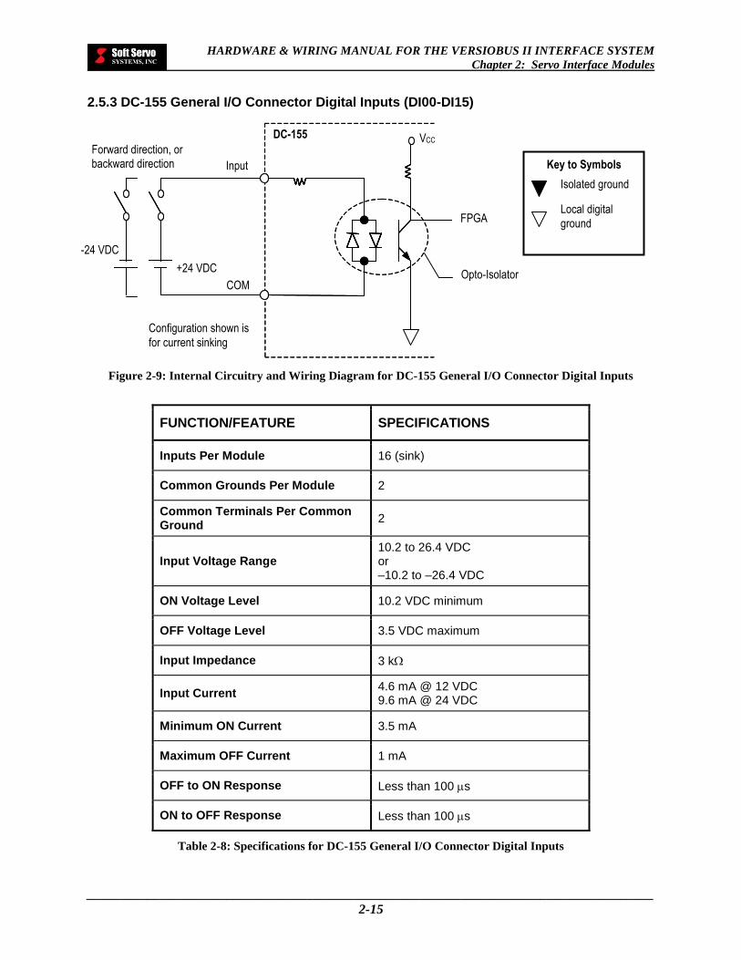
HARDWARE & WIRING MANUAL FOR THE VERSIOBUS II INTERFACE SYSTEM
Chapter 2: Servo Interface Modules
_____________________________________________________________________________________
2-15
2.5.3 DC-155 General I/O Connector Digital Inputs (DI00-DI15)
Figure 2-9: Internal Circuitry and Wiring Diagram for DC-155 General I/O Connector Digital Inputs
FUNCTION/FEATURE SPECIFICATIONS
Inputs Per Module 16 (sink)
Common Grounds Per Module 2
Common Terminals Per Common Ground
2
Input Voltage Range 10.2 to 26.4 VDC or –10.2 to –26.4 VDC
ON Voltage Level 10.2 VDC minimum
OFF Voltage Level 3.5 VDC maximum
Input Impedance 3 k
Input Current 4.6 mA @ 12 VDC 9.6 mA @ 24 VDC
Minimum ON Current 3.5 mA
Maximum OFF Current 1 mA
OFF to ON Response Less than 100 s
ON to OFF Response Less than 100 s
Table 2-8: Specifications for DC-155 General I/O Connector Digital Inputs
Key to Symbols
Isolated ground
Local digital
ground FPGA
Input
Configuration shown is
for current sinking
VCC
COM
+24 VDC Opto-Isolator
DC-155
-24 VDC
Forward direction, or backward direction

HARDWARE & WIRING MANUAL FOR THE VERSIOBUS II INTERFACE SYSTEM
Chapter 2: Servo Interface Modules
_____________________________________________________________________________________
2-16
2.5.4 DC-155 General I/O Connector Digital Outputs (DO00-DO15)
Figure 2-10: Internal Circuitry and Wiring Diagram for DC-155 General I/O Connector Digital Outputs
Key to Symbols
Isolated ground
Ground of FPGA
circuits
NOTE: If the load is a solenoid or a coil of an electromagnetic / mechanical relay, a high-speed fly-back diode must be installed across the load with the cathode end
connected to VIN.
Load (DC Coil Relay)
Output
High-Speed Fly-
Back Diode
VIN
VCC
COM
Output
12-24 VDC
Opto-Isolator
DC-155
FPGA
Load
R

HARDWARE & WIRING MANUAL FOR THE VERSIOBUS II INTERFACE SYSTEM
Chapter 2: Servo Interface Modules
_____________________________________________________________________________________
2-17
FUNCTION/FEATURE SPECIFICATIONS
Outputs Per Module 16 (sink)
Common Grounds Per Module 2
Common Terminals Per Common Ground
5
Operating Range 10.8 to 26.4 VDC or –10.8 to –26.4 VDC
Type Opto-isolated
Peak Voltage 30 VDC
On Voltage Drop 0.1 VDC maximum
Maximum Load Current 100 mA per point 500 mA per common ground 100 mA per common terminal
Maximum Leakage Current 0.1 mA
External DC Required 12–24 VDC ±10%, 200 mA maximum
OFF to ON Response Less than 100 s
ON to OFF Response Less than 100 s
Table 2-9: Specifications for DC-155 General I/O Connector Digital Outputs

HARDWARE & WIRING MANUAL FOR THE VERSIOBUS II INTERFACE SYSTEM
Chapter 2: Servo Interface Modules
_____________________________________________________________________________________
2-18
2.6 DC-155 Schematic Servo Motor and Encoder Connections
Both essential and optional connections required to operate the servo motor are shown. You can interface either
directly to the servo amplifier or directly with the encoder.
2.6.1 Axis Arrangement #1: Essential Servo Motor Connections in the VersioBus II System When the Servo Amplifier Provides the Encoder Signals
Figure 2-11: Wiring Diagram for Essential Servo Motor Connections in the VersioBus II System When the
Servo Amplifier Provides the Encoder Signals
Analog Ground +
Analog Command + / - 10V
Amp Fault
Amp Enable (Servo On)
Digital Ground
Encoder A+
Encoder A -
Encoder B+
Encoder B -
Encoder Z+
Encoder Z -
36 18
4
26
35
16
34
15
33
14
32
Servo Amplifier Motor Encoder DC-155
Axis Connector
For each axis, up to 4 axes
NOTE: The differential encoder input signals (A+/A–, B+/B– and Z+/Z–) must conform to Standard TIA/EIA-422-B (RS-422) or ITU-TV.11. The common mode voltage range is +/–7V and the differential
signal range is from 0.2 to 3V.

HARDWARE & WIRING MANUAL FOR THE VERSIOBUS II INTERFACE SYSTEM
Chapter 2: Servo Interface Modules
_____________________________________________________________________________________
2-19
2.6.2 Axis Arrangement #2: Essential Servo Motor Connections in the VersioBus II System When the Signals Come Directly From the Encoder
Figure 2-12: Wiring Diagram for Essential Servo Motor Connections in the VersioBus II System When the
Signals Come Directly From the Encoder
36
18
4
26
35
12
16
34
15
33
14
32
NOTE: The differential encoder input signals (A+/A–, B+/B– and Z+/Z–) must conform to Standard TIA/EIA-422-B (RS-422) or ITU-TV.11. The common mode voltage range is +/–7V and the
differential signal range is from 0.2 to 3V.
Analog Ground +
Analog Command + / - 10V
Amp Fault
Amp Enable (Servo On)
Digital Ground
+5 volts (1000 mA/unit max.)
Encoder A+
Encoder A -
Encoder B+
Encoder B -
Encoder Z+
Encoder Z -
Servo Amplifier Motor Encoder DC-155
Axis Connector
For each axis, up to
4 axes
+0.5 –0
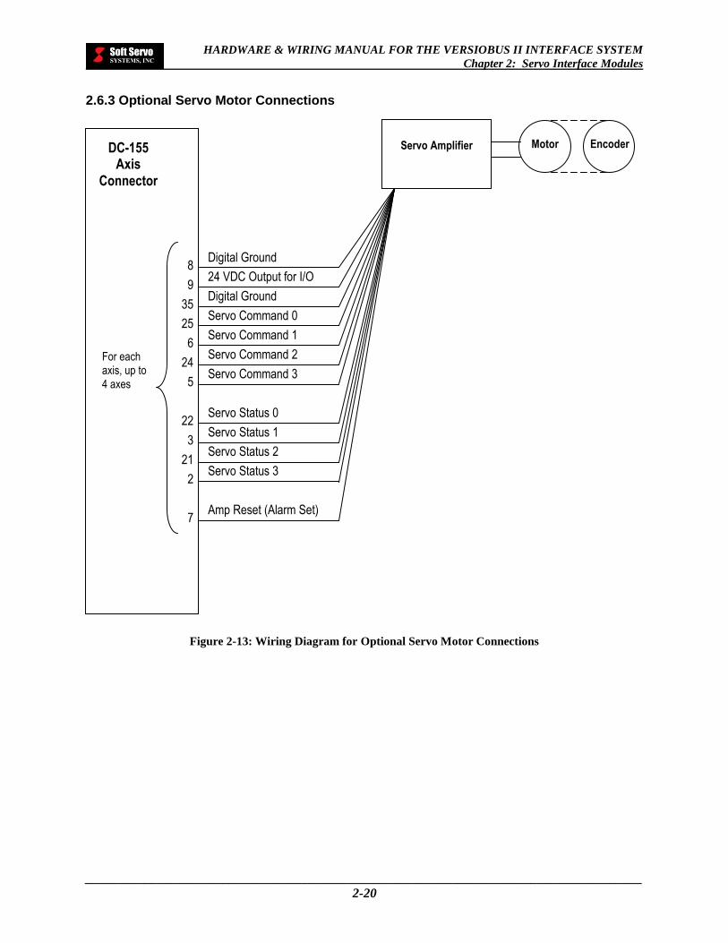
HARDWARE & WIRING MANUAL FOR THE VERSIOBUS II INTERFACE SYSTEM
Chapter 2: Servo Interface Modules
_____________________________________________________________________________________
2-20
2.6.3 Optional Servo Motor Connections
Figure 2-13: Wiring Diagram for Optional Servo Motor Connections
8
9
35
25
6
24
5
22
3
21
2
7
Digital Ground
24 VDC Output for I/O
Digital Ground
Servo Command 0
Servo Command 1
Servo Command 2
Servo Command 3
Servo Status 0
Servo Status 1
Servo Status 2
Servo Status 3
Amp Reset (Alarm Set)
Servo Amplifier Motor Encoder DC-155
Axis Connector
For each axis, up to 4 axes

HARDWARE & WIRING MANUAL FOR THE VERSIOBUS II INTERFACE SYSTEM
Chapter 2: Servo Interface Modules
_____________________________________________________________________________________
2-21
2.6.4 Typical Connection Between a Differential Encoder and the DC-155
Figure 2-14: Wiring Diagram for a Typical Connection Between a Differential Encoder and the DC-155
NOTE: Do not connect any signal grounds to the earth ground.
Key to Symbols
P indicates a twisted pair
16
34
15 33
14 32 35 12
36
Differential Encoder
DC-155 Axis
Connector
A+ A– B+ B– Z+ Z– Line Rec. +5V AGND
Encoder A+
Encoder A– P
Encoder B+
Encoder B– P
Encoder Z+ Encoder Z–
P
+5 volts Analog Ground
Line Receivers
220 Ω
220 Ω
220 Ω
Cable shield
Connector Shell Shield line
VCC
+0.5 –0
Encoder Power –
DC-155 Only
Signal Ground

HARDWARE & WIRING MANUAL FOR THE VERSIOBUS II INTERFACE SYSTEM
Chapter 2: Servo Interface Modules
_____________________________________________________________________________________
2-22
2.7 Cable Connections – DC-155 to Specific Servo Drives
The following pages contain schematics for the direct cable connection between the DC-155 axis connector, and
specific servo drives for several manufacturers. The manufacturer’s name and the servo drive model are included.
Key to Tables
T-REF A connector pin in gray text indicates that this connector pin is unused.
PAO ———————————— This symbol indicates that these two wires are a twisted pair.
*PAO ————————————
Figure 2-15: Key to Recommended Direct Cable Connections Tables
P

HARDWARE & WIRING MANUAL FOR THE VERSIOBUS II INTERFACE SYSTEM
Chapter 2: Servo Interface Modules
_____________________________________________________________________________________
2-23
2.7.1 Recommended Direct Cable Connections Between the DC-155 Axis Connector & the YASKAWA Sigma I (SGDA) Servo Drive (Incremental Encoder)
SGDA 1CN DC-155 AXIS CONNECTOR TB36A TB36B
Signal Name
Connector Pin #
Connector
Pin # AXIS Signal
Servo Function Corresponding
Pin #’s
T-REF 1
SG–T 2
V–REF 3 ——————————————
18 A OUT Analog Command 1-1 18
SG–V 4 ——————————————
36 AGND Analog Ground 1-2 36
SEN 5
0SEN 6
/BK 7
/V–CMP 8
/TGON 9
SG–COM 10
/P–CL 11
/N–CL 12
+24VIN 13 ——————————————
9 VOUT Isolated 24 VDC Output 2-1 9
/S–ON 14 ——————————————
26 SVON Amp Enable (Servo On) 2-4 26
/P–CON 15
P–OT 16
N–OT 17
/ALMRST 18 ——————————————
7 RST Amp Reset (Alarm Reset) 2-5 7
SG–PG 19 ——————————————
35 SG Signal Ground 1-4 35
PAO 20 ——————————————
16 E_A_H Encoder Signal A, High Side 1-5 16
*PAO 21 ——————————————
34 E_A_L Encoder Signal A, Low Side 1-6 34
PBO 22 ——————————————
15 E_B_H Encoder Signal B, High Side 1-7 15
*PBO 23 ——————————————
33 E_B_L Encoder Signal B, Low Side 1-8 33
PCO 24 ——————————————
14 E_Z_H Encoder Signal Z, High Side 1-9 14
*PCO 25 ——————————————
32 E_Z_L Encoder Signal Z, Low Side 1-10 32
PSO 26
*PSO 27
BAT 28
BAT0 29
ALO1 30
ALO2 31
ALO3 32
SG–AL 33
ALM 34 ——————————————
4 FAULT Amp Fault 2-11 4
ALM–SG 35 ——————————————
23 GND Digital Ground (Isolated) 2-10 23
FG 36
Connector Case
Table 2-10: Recommended Direct Cable Connections to the YASKAWA Sigma I (SGDA) Servo Drive
P
P
P
P
P

HARDWARE & WIRING MANUAL FOR THE VERSIOBUS II INTERFACE SYSTEM
Chapter 2: Servo Interface Modules
_____________________________________________________________________________________
2-24
2.7.2 Recommended Direct Cable Connections Between the DC-155 Axis Connector & the YASKAWA Sigma I (SGDB) Servo Drive (Incremental Encoder)
SGDB 1CN DC-155 AXIS CONNECTOR TB36A TB36B
Signal Name
Connector Pin #
Connector
Pin # AXIS Signal
Servo Function Corresponding
Pin #’s
T-REF 9
SG 10
V–REF 5 ——————————————
18 A OUT Analog Command 1-1 18
SG–V 6 ——————————————
36 AGND Analog Ground 1-2 36
SEN 4
SG 1
PL1 3
PL2 13
/TGON+ 27 ——————————————
22 SS0 Servo Status 0 2-12 22
/TGON- 28 ——————————————
23 GND Digital Ground (Isolated) 2-10 23
/P–CL 45
/N–CL 46
+24VIN 47 ——————————————
9 VOUT Isolated 24 VDC Output 2-1 9
/S–ON 40 ——————————————
26 SVON Amp Enable (Servo On) 2-4 26
/P–CON 41
P–OT 42
N–OT 43
/ALMRST 44 ——————————————
7 RST Amp Reset (Alarm Reset) 2-5 7
SG 2 ——————————————
35 SG Signal Ground 1-4 35
PAO 33 ——————————————
16 E_A_H Encoder Signal A, High Side 1-5 16
*PAO 34 ——————————————
34 E_A_L Encoder Signal A, Low Side 1-6 34
PBO 35 ——————————————
15 E_B_H Encoder Signal B, High Side 1-7 15
*PBO 36 ——————————————
33 E_B_L Encoder Signal B, Low Side 1-8 33
PCO 19 ——————————————
14 E_Z_H Encoder Signal Z, High Side 1-9 14
*PCO 20 ——————————————
32 E_Z_L Encoder Signal Z, Low Side 1-10 32
PSO 48
*PSO 49
BAT 21
BAT0 22
ALO1 37
ALO2 38
ALO3 39
PL3 18
ALM+ 31 ——————————————
4 FAULT Amp Fault 2-11 4
ALM– 32 ——————————————
23 GND Digital Ground (Isolated) 2-10 23
FG 50
Connector Case
Table 2-11: Recommended Direct Cable Connections to the YASKAWA Sigma I (SGDB) Servo Drive
P
P
P
P
P
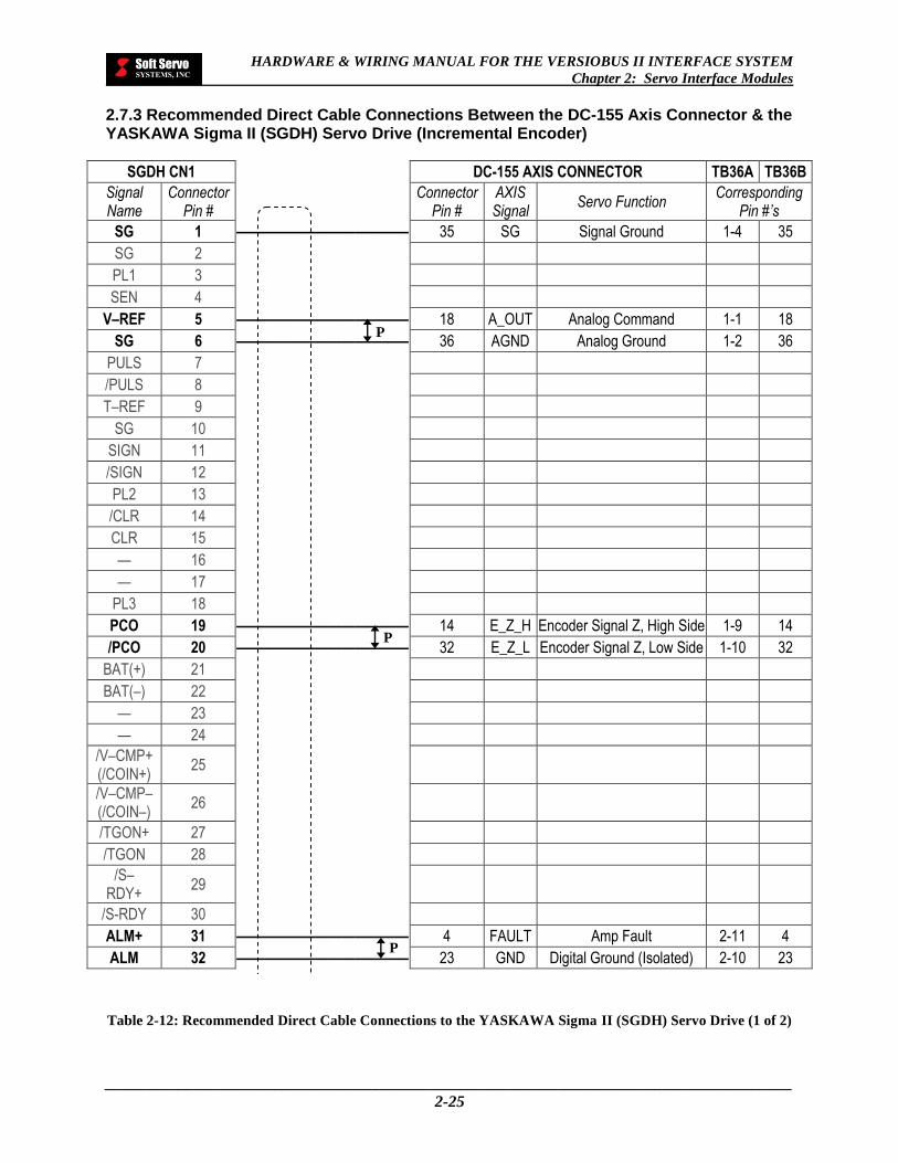
HARDWARE & WIRING MANUAL FOR THE VERSIOBUS II INTERFACE SYSTEM
Chapter 2: Servo Interface Modules
_____________________________________________________________________________________
2-25
2.7.3 Recommended Direct Cable Connections Between the DC-155 Axis Connector & the YASKAWA Sigma II (SGDH) Servo Drive (Incremental Encoder)
SGDH CN1 DC-155 AXIS CONNECTOR TB36A TB36B
Signal Name
Connector Pin #
Connector Pin #
AXIS Signal
Servo Function Corresponding
Pin #’s
SG 1 ————————————— 35 SG Signal Ground 1-4 35
SG 2
PL1 3
SEN 4
V–REF 5 ————————————— 18 A_OUT Analog Command 1-1 18
SG 6 ————————————— 36 AGND Analog Ground 1-2 36
PULS 7
/PULS 8
T–REF 9
SG 10
SIGN 11
/SIGN 12
PL2 13
/CLR 14
CLR 15
— 16
— 17
PL3 18
PCO 19 ————————————— 14 E_Z_H Encoder Signal Z, High Side 1-9 14
/PCO 20 ————————————— 32 E_Z_L Encoder Signal Z, Low Side 1-10 32
BAT(+) 21
BAT(–) 22
— 23
— 24
/V–CMP+ (/COIN+)
25
/V–CMP– (/COIN–)
26
/TGON+ 27
/TGON 28
/S– RDY+
29
/S-RDY 30
ALM+ 31 ————————————— 4 FAULT Amp Fault 2-11 4
ALM 32 ————————————— 23 GND Digital Ground (Isolated) 2-10 23
Table 2-12: Recommended Direct Cable Connections to the YASKAWA Sigma II (SGDH) Servo Drive (1 of 2)
P
P
P

HARDWARE & WIRING MANUAL FOR THE VERSIOBUS II INTERFACE SYSTEM
Chapter 2: Servo Interface Modules
_____________________________________________________________________________________
2-26
SGDH CN1 DC-155 AXIS CONNECTOR TB36A TB36B
Signal Name
Connector Pin #
Connector
Pin # AXIS Signal
Servo Function Corresponding
Pin #’s
PAO 33 ————————————— 16 E_A_H Encoder Signal A, High Side 1-5 16
/PAO 34 ————————————— 34 E_A_L Encoder Signal A, Low Side 1-6 34
PBO 35 ————————————— 15 E_B_H Encoder Signal B, High Side 1-7 15
/PBO 36 ————————————— 33 E_B_L Encoder Signal B, Low Side 1-8 33
AL01 37
AL02 38
AL03 39
/S–ON 40 ————————————— 26 SVON Amp Enable (Servo On) 2-4 26
P–CON 41
P–OT 42
N–OT 43
/ALM– RST
44 ————————————— 7 RST Amp Reset (Alarm Reset) 2-5 7
/P–CL 45
/N–CL 46
+24V –IN
47 ————————————— 9 VOUT Isolated 24 VDC Output 2-1 9
PSO 48
*PSO 49
FG 50
Connector Case
Table 2-13: Recommended Direct Cable Connections to the YASKAWA Sigma II (SGDH) Servo Drive (2 of 2)
P
P

HARDWARE & WIRING MANUAL FOR THE VERSIOBUS II INTERFACE SYSTEM
Chapter 2: Servo Interface Modules
_____________________________________________________________________________________
2-27
2.7.4 Recommended Direct Cable Connections Between the DC-155 Axis Connector & the Mitsubishi MELSERVO-J2-A Servo Drive (Incremental Encoder)
MELSERVO CN1A DC-155 AXIS CONNECTOR TB36A TB36B
Signal Name
Connector Pin #
Connector
Pin # AXIS Signal
Servo Function Corresponding
Pin #’s
LG 1
X 2
X 3
P15R 4
LZ 5 ——————————————
14 E_Z_H Encoder Signal Z, High Side 1-9 14
LA 6 ——————————————
16 E_A_H Encoder Signal A, High Side 1-5 16
LB 7 ——————————————
15 E_B_H Encoder Signal B, High Side 1-7 15
SP1 8
COM 9
SG 10
X 11
X 12
X 13
OP 14
LZR 15 ——————————————
32 E_Z_L Encoder Signal Z, Low Side 1-10 32
LAR 16 ——————————————
34 E_A_L Encoder Signal A, Low Side 1-6 34
LBR 17 ——————————————
33 E_B_L Encoder Signal B, Low Side 1-8 33
SA 18
RD 19
SG 20
Table 2-14: Recommended Direct Cable Connections to the Mitsubishi MELSERVO-J2-A Servo Drive (1 of 2)
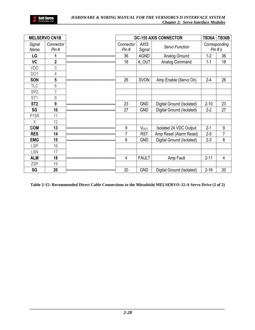
HARDWARE & WIRING MANUAL FOR THE VERSIOBUS II INTERFACE SYSTEM
Chapter 2: Servo Interface Modules
_____________________________________________________________________________________
2-28
MELSERVO CN1B DC-155 AXIS CONNECTOR TB36A TB36B
Signal Name
Connector Pin #
Connector
Pin # AXIS Signal
Servo Function Corresponding
Pin #’s
LG 1 ——————————————
36 AGND Analog Ground 1-2 36
VC 2 ——————————————
18 A_OUT Analog Command 1-1 18
VDD 3
DO1 4
SON 5 ——————————————
26 SVON Amp Enable (Servo On) 2-4 26
TLC 6
SP2 7
ST1 8
ST2 9 ————————————— 23 GND Digital Ground (Isolated) 2-10 23
SG 10 ————————————— 27 GND Digital Ground (Isolated) 2-2 27
P15R 11
X 12
COM 13 ——————————————
9 VOUT Isolated 24 VDC Output 2-1 9
RES 14 ——————————————
7 RST Amp Reset (Alarm Reset) 2-5 7
EMG 15 ————————————— 8 GND Digital Ground (Isolated) 2-3 8
LSP 16
LSN 17
ALM 18 ——————————————
4 FAULT Amp Fault 2-11 4
ZSP 19
SG 20 ——————————————
20 GND Digital Ground (Isolated) 2-16 20
Table 2-15: Recommended Direct Cable Connections to the Mitsubishi MELSERVO-J2-A Servo Drive (2 of 2)

HARDWARE & WIRING MANUAL FOR THE VERSIOBUS II INTERFACE SYSTEM
Chapter 2: Servo Interface Modules
_____________________________________________________________________________________
2-29
2.8 FPGA Hardware Shell Architecture
2.8.1 FPGA Hardware Shell Architecture for AC and DC Motors
Figure 2-16: Schematic Diagram: DC-155 FPGA Hardware Shell Architecture for AC and DC Motors
Servo Drives, AC / DC Motors,
Encoders
Switches, Relays
40 MHz Clock Configuration
PROM
Fiber optic transceiver
Fiber optic transceiver
VersioBus Connections
Analog Command
Servo Command
FPGA
Encoder Pulse
(A/B/Z)
VersioBus Connections
DC-155
Servo Status
Digital I/O
FPGA
Fiber optic transceiver
FP-85/105/ 114
FPGA
16-bit DAC +/-10 V
or 0-10V TO OTHER DAISY-
CHAINED
DC-155s
Machine
Dip-switch
DC-155
ID Select

HARDWARE & WIRING MANUAL FOR THE VERSIOBUS II INTERFACE SYSTEM
Chapter 2: Servo Interface Modules
_____________________________________________________________________________________
2-30
2.8.2 FPGA Hardware Shell Architecture for Linear Scales
Figure 2-17: Schematic Diagram: DC-155 FPGA Hardware Shell Architecture for Linear Scales
40 MHz Clock
Linear Scales
Configuration PROM
16-bit DAC +/-10 V
or 0-10V
Fiber optic transceiver
Fiber optic transceiver VersioBus
Connections
VersioBus Connections
FPGA
DC-155
Encoder Pulse (A/B)
FPGA
TO OTHER DAISY-
CHAINED
DC-155s Machine
Dip-switch
DC-155
ID Select
FPGA
Fiber optic transceiver
FP-85/105/ 114

HARDWARE & WIRING MANUAL FOR THE VERSIOBUS II INTERFACE SYSTEM
Chapter 2: Servo Interface Modules
_____________________________________________________________________________________
2-31
2.9 DC-125J Servo Interface Module
The DC-125J servo interface module replaces the discontinued DC-155 servo interface module.
2.9.1 DC-125J Diagrams
Figure 2-18: DC-125J Dimensions in Millimeters
2.9.2 DC-125J Functional Specifications
FUNCTION/FEATURE SPECIFICATIONS
Communications VersioBus II (a proprietary 5 Mbps real-time fiber-optic communication protocol) connections
Servo Axes 4 axes
Daisy Chainable (Scalable) Up to 4 DC-155s (maximum 16-axis control)
Connectors
6 × 36 pin IEEE 1284 MDR connector (4 × AXIS, 2 × I/O) Recommended connector and shell:
3M™ 10136-3000VE [Mini D Ribbon (MDR) Connectors, Wiremount Plugs & Accessories, Solder Plug Connector, Non-RoHS Compliant]
3M™ 10336-52F0-008 [Mini D Ribbon (MDR) Connectors, Plastic Solder Plug Junction Shell, Non Shielded]
Servo Types DC and AC servo motors
Table 2-16: DC-125J Functional Specifications (1 of 2)
205 mm
195 mm
80 m
m
106
mm
116
mm
9.5
mm
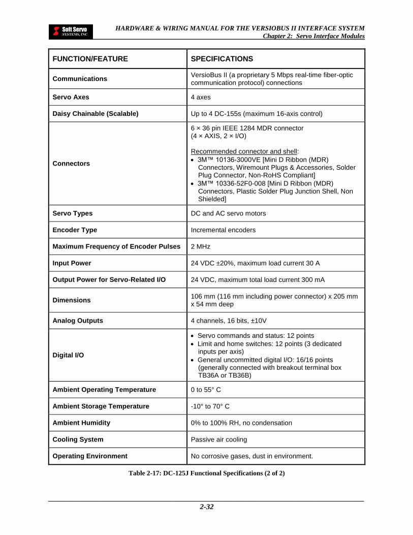
HARDWARE & WIRING MANUAL FOR THE VERSIOBUS II INTERFACE SYSTEM
Chapter 2: Servo Interface Modules
_____________________________________________________________________________________
2-32
FUNCTION/FEATURE SPECIFICATIONS
Communications VersioBus II (a proprietary 5 Mbps real-time fiber-optic communication protocol) connections
Servo Axes 4 axes
Daisy Chainable (Scalable) Up to 4 DC-155s (maximum 16-axis control)
Connectors
6 × 36 pin IEEE 1284 MDR connector (4 × AXIS, 2 × I/O) Recommended connector and shell:
3M™ 10136-3000VE [Mini D Ribbon (MDR) Connectors, Wiremount Plugs & Accessories, Solder Plug Connector, Non-RoHS Compliant]
3M™ 10336-52F0-008 [Mini D Ribbon (MDR) Connectors, Plastic Solder Plug Junction Shell, Non Shielded]
Servo Types DC and AC servo motors
Encoder Type Incremental encoders
Maximum Frequency of Encoder Pulses 2 MHz
Input Power 24 VDC ±20%, maximum load current 30 A
Output Power for Servo-Related I/O 24 VDC, maximum total load current 300 mA
Dimensions 106 mm (116 mm including power connector) x 205 mm x 54 mm deep
Analog Outputs 4 channels, 16 bits, ±10V
Digital I/O
Servo commands and status: 12 points
Limit and home switches: 12 points (3 dedicated inputs per axis)
General uncommitted digital I/O: 16/16 points (generally connected with breakout terminal box TB36A or TB36B)
Ambient Operating Temperature 0 to 55° C
Ambient Storage Temperature -10° to 70° C
Ambient Humidity 0% to 100% RH, no condensation
Cooling System Passive air cooling
Operating Environment No corrosive gases, dust in environment.
Table 2-17: DC-125J Functional Specifications (2 of 2)
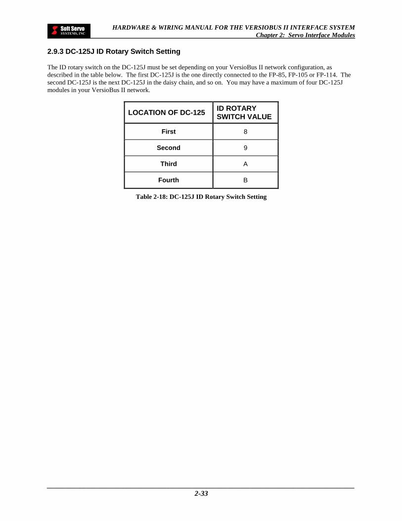
HARDWARE & WIRING MANUAL FOR THE VERSIOBUS II INTERFACE SYSTEM
Chapter 2: Servo Interface Modules
_____________________________________________________________________________________
2-33
2.9.3 DC-125J ID Rotary Switch Setting
The ID rotary switch on the DC-125J must be set depending on your VersioBus II network configuration, as
described in the table below. The first DC-125J is the one directly connected to the FP-85, FP-105 or FP-114. The
second DC-125J is the next DC-125J in the daisy chain, and so on. You may have a maximum of four DC-125J
modules in your VersioBus II network.
LOCATION OF DC-125 ID ROTARY SWITCH VALUE
First 8
Second 9
Third A
Fourth B
Table 2-18: DC-125J ID Rotary Switch Setting

HARDWARE & WIRING MANUAL FOR THE VERSIOBUS II INTERFACE SYSTEM
Chapter 2: Servo Interface Modules
_____________________________________________________________________________________
2-34
2.9.4 DC-125J Pin Assignments
2.9.4.1 Axis Connector Pin Assignments (Axis 1-4 Connectors)
PIN NO. NAME I/O I/O
TYPE SERVO FUNCTION
1
2
3
4 FAULT I IN1 Amp Fault (Amp Alarm)
5
6
7 RST O OUT1 Amp Reset (Alarm Reset)
8 IO_GND I/O Ground
9 IO_24V 24V VDC Output for I/O
10
11
12
13
14 Z I IN3 Encoder Signal Z, High Side
15 B I IN3 Encoder Signal B, High Side
16 A I IN3 Encoder Signal A, High Side
17
18 A_OUT O OUT4 Analog Command Output, ±10V
19 GND Encoder Ground
20 IO_GND I/O Ground
21
22
23 IO_GND I/O Ground
24
25
26 SVON O OUT1 Amp Enable (Servo On)
27 IO_GND I/O Ground
28
29
30 IO_GND I/O Ground
31
32 nZ I IN3 Encoder Signal Z, Low Side
33 nB I IN3 Encoder Signal B, Low Side
34 nA I IN3 Encoder Signal A, Low Side
35 GND Encoder Ground
36 AGND Analog Ground
*See Section 2.9.5: DC-125J Internal Circuitry and Wiring Diagrams for more information regarding each of the
input and output types.
Table 2-19: DC-125J Axis Connector Pin Assignments (Axis 1-4 Connectors)

HARDWARE & WIRING MANUAL FOR THE VERSIOBUS II INTERFACE SYSTEM
Chapter 2: Servo Interface Modules
_____________________________________________________________________________________
2-35
2.9.4.2 General I/O Connector Pin Assignments – I/O Connector 1
PIN NO. NAME I/O I/O
TYPE SERVO AND I/O FUNCTION
1 O_COM Output Common (Ground)
2 OUT6 O OUT2 Digital Output 6
3 OUT4 O OUT2 Digital Output 4
4 OUT3 O OUT2 Digital Output 3
5 OUT1 O OUT2 Digital Output 1
6 O_COM Output Common (Ground)
7
8
9
10 IN7 I IN2 Digital Input 7
11 IN5 I IN2 Digital Input 5
12 IN3 I IN2 Digital Input 3
13 IN1 I IN2 Digital Input 1
14 I_COM
15 NLS1 I IN2 Negative Limit Switch 1
16
17 NLS0 I IN2 Negative Limit Switch 0
18
19 O_COM Output Common (Ground)
20 OUT7 O OUT2 Digital Output 7
21 OUT5 O OUT2 Digital Output 5
22 O_COM Output Common (Ground)
23 OUT2 O OUT2 Digital Output 2
24 OUT0 O OUT2 Digital Output 0
25 O_COM Output Common (Ground)
26
27
28 I_COM
29 IN6 I IN2 Digital Input 6
30 IN4 I IN2 Digital Input 4
31 IN2 I IN2 Digital Input 2
32 IN0 I IN2 Digital Input 0
33 PLS1 I IN2 Positive Limit Siwtch 1
34 HS1 I IN2 Home Switch 1
35 PLS0 I IN2 Positive Limit Switch 0
36 HS0 I IN2 Home Switch 0
*See Section 2.9.5: DC-125J Internal Circuitry and Wiring Diagrams for more information regarding each of the
input and output types.
Table 2-20: DC-125J General I/O Connector Pin Assignments (I/O Connector 1)
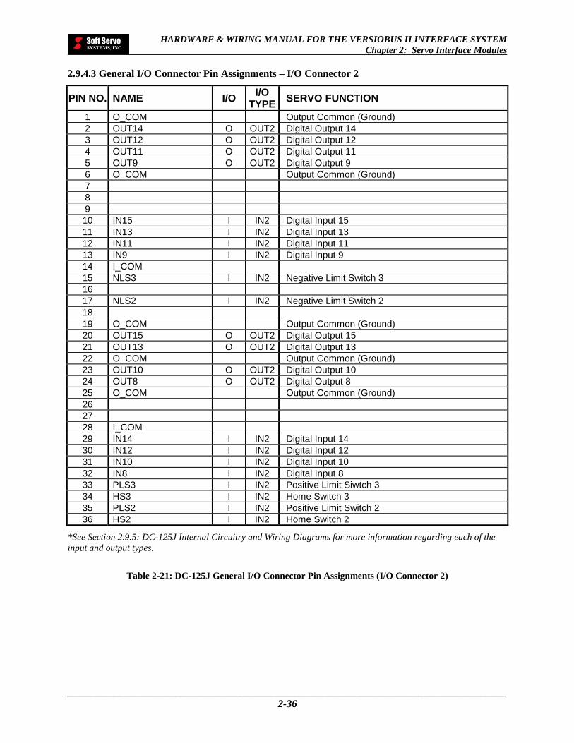
HARDWARE & WIRING MANUAL FOR THE VERSIOBUS II INTERFACE SYSTEM
Chapter 2: Servo Interface Modules
_____________________________________________________________________________________
2-36
2.9.4.3 General I/O Connector Pin Assignments – I/O Connector 2
PIN NO. NAME I/O I/O
TYPE SERVO FUNCTION
1 O_COM Output Common (Ground)
2 OUT14 O OUT2 Digital Output 14
3 OUT12 O OUT2 Digital Output 12
4 OUT11 O OUT2 Digital Output 11
5 OUT9 O OUT2 Digital Output 9
6 O_COM Output Common (Ground)
7
8
9
10 IN15 I IN2 Digital Input 15
11 IN13 I IN2 Digital Input 13
12 IN11 I IN2 Digital Input 11
13 IN9 I IN2 Digital Input 9
14 I_COM
15 NLS3 I IN2 Negative Limit Switch 3
16
17 NLS2 I IN2 Negative Limit Switch 2
18
19 O_COM Output Common (Ground)
20 OUT15 O OUT2 Digital Output 15
21 OUT13 O OUT2 Digital Output 13
22 O_COM Output Common (Ground)
23 OUT10 O OUT2 Digital Output 10
24 OUT8 O OUT2 Digital Output 8
25 O_COM Output Common (Ground)
26
27
28 I_COM
29 IN14 I IN2 Digital Input 14
30 IN12 I IN2 Digital Input 12
31 IN10 I IN2 Digital Input 10
32 IN8 I IN2 Digital Input 8
33 PLS3 I IN2 Positive Limit Siwtch 3
34 HS3 I IN2 Home Switch 3
35 PLS2 I IN2 Positive Limit Switch 2
36 HS2 I IN2 Home Switch 2
*See Section 2.9.5: DC-125J Internal Circuitry and Wiring Diagrams for more information regarding each of the
input and output types.
Table 2-21: DC-125J General I/O Connector Pin Assignments (I/O Connector 2)

HARDWARE & WIRING MANUAL FOR THE VERSIOBUS II INTERFACE SYSTEM
Chapter 2: Servo Interface Modules
_____________________________________________________________________________________
2-37
2.9.5 DC-125J Internal Circuitry and Wiring Diagrams
2.9.5.1 DC-125J IN1 (Servo-Related Digital Inputs)
Figure 2-19: Internal Circuitry and Wiring Diagram for DC-125J IN1 Inputs
FUNCTION/FEATURE SPECIFICATIONS
Source/Sink Source
Operating Voltage 24V
Table 2-22: Specifications for DC-125J IN1 Inputs
2.9.5.2 DC-125J OUT1 (Servo-Related Digital Outputs)
Figure 2-20: Internal Circuitry and Wiring Diagram for DC-125J OUT1 Outputs
FUNCTION/FEATURE SPECIFICATIONS
Source/Sink Sink
Operating Voltage 24V
Max Current 50 mA
Table 2-23: Specifications for DC-125J OUT1 Outputs
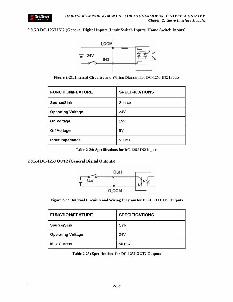
HARDWARE & WIRING MANUAL FOR THE VERSIOBUS II INTERFACE SYSTEM
Chapter 2: Servo Interface Modules
_____________________________________________________________________________________
2-38
2.9.5.3 DC-125J IN 2 (General Digital Inputs, Limit Switch Inputs, Home Switch Inputs)
Figure 2-21: Internal Circuitry and Wiring Diagram for DC-125J IN2 Inputs
FUNCTION/FEATURE SPECIFICATIONS
Source/Sink Source
Operating Voltage 24V
On Voltage 15V
Off Voltage 5V
Input Impedance 5.1 kΩ
Table 2-24: Specifications for DC-125J IN2 Inputs
2.9.5.4 DC-125J OUT2 (General Digital Outputs)
Figure 2-22: Internal Circuitry and Wiring Diagram for DC-125J OUT2 Outputs
FUNCTION/FEATURE SPECIFICATIONS
Source/Sink Sink
Operating Voltage 24V
Max Current 50 mA
Table 2-25: Specifications for DC-125J OUT2 Outputs
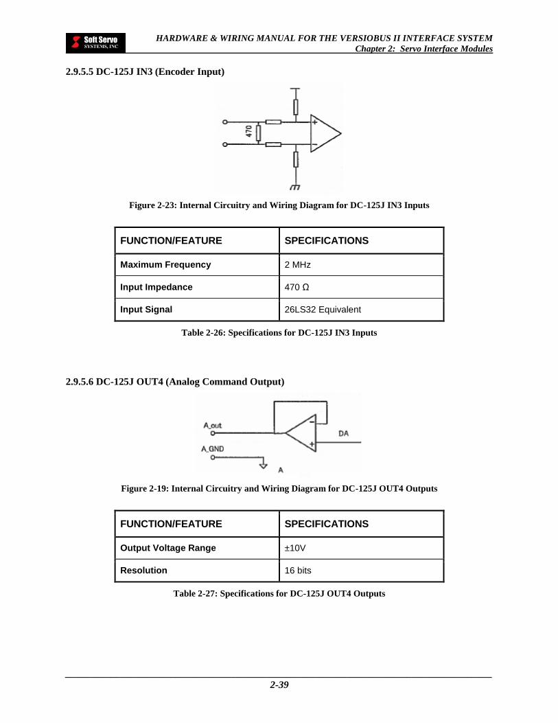
HARDWARE & WIRING MANUAL FOR THE VERSIOBUS II INTERFACE SYSTEM
Chapter 2: Servo Interface Modules
_____________________________________________________________________________________
2-39
2.9.5.5 DC-125J IN3 (Encoder Input)
Figure 2-23: Internal Circuitry and Wiring Diagram for DC-125J IN3 Inputs
FUNCTION/FEATURE SPECIFICATIONS
Maximum Frequency 2 MHz
Input Impedance 470 Ω
Input Signal 26LS32 Equivalent
Table 2-26: Specifications for DC-125J IN3 Inputs
2.9.5.6 DC-125J OUT4 (Analog Command Output)
Figure 2-19: Internal Circuitry and Wiring Diagram for DC-125J OUT4 Outputs
FUNCTION/FEATURE SPECIFICATIONS
Output Voltage Range ±10V
Resolution 16 bits
Table 2-27: Specifications for DC-125J OUT4 Outputs
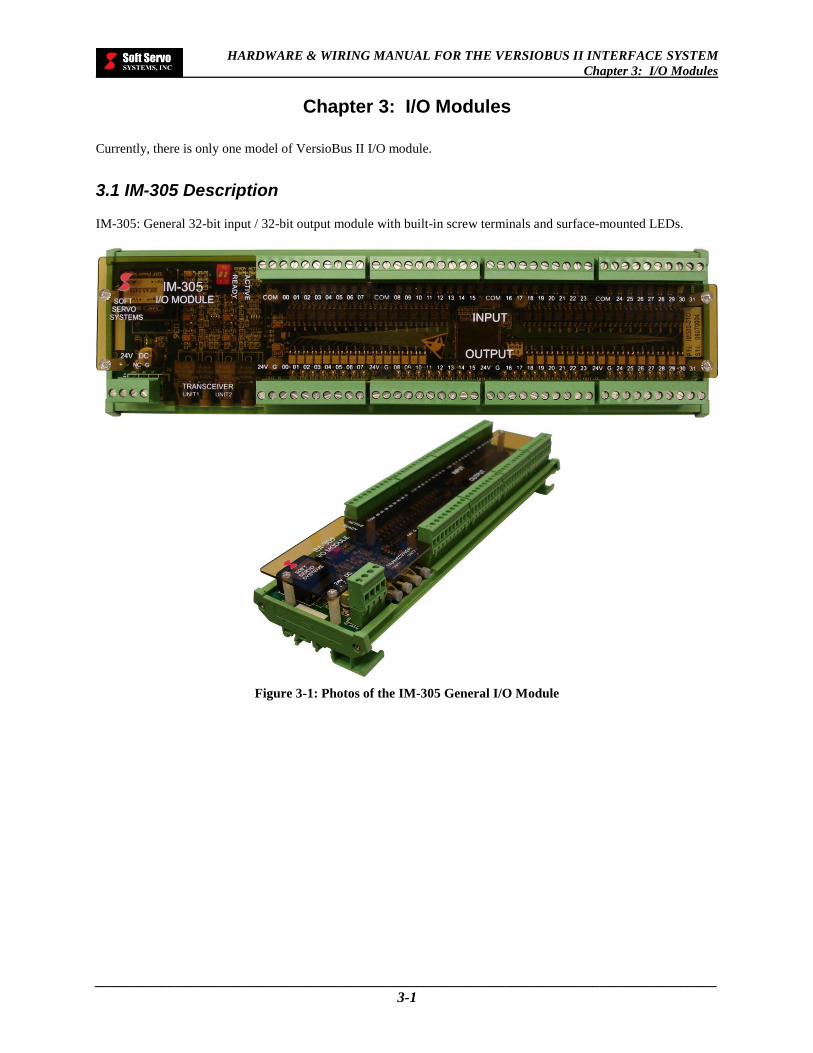
HARDWARE & WIRING MANUAL FOR THE VERSIOBUS II INTERFACE SYSTEM
Chapter 3: I/O Modules
_____________________________________________________________________________________
3-1
Chapter 3: I/O Modules
Currently, there is only one model of VersioBus II I/O module.
3.1 IM-305 Description
IM-305: General 32-bit input / 32-bit output module with built-in screw terminals and surface-mounted LEDs.
Figure 3-1: Photos of the IM-305 General I/O Module
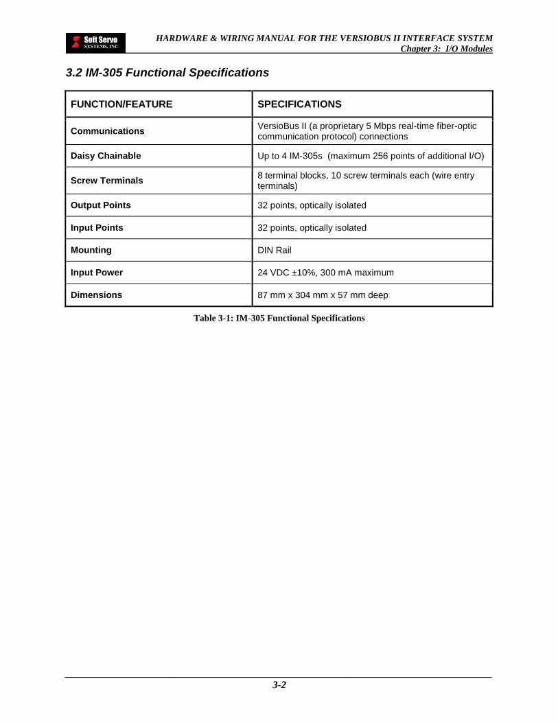
HARDWARE & WIRING MANUAL FOR THE VERSIOBUS II INTERFACE SYSTEM
Chapter 3: I/O Modules
_____________________________________________________________________________________
3-2
3.2 IM-305 Functional Specifications
FUNCTION/FEATURE SPECIFICATIONS
Communications VersioBus II (a proprietary 5 Mbps real-time fiber-optic communication protocol) connections
Daisy Chainable Up to 4 IM-305s (maximum 256 points of additional I/O)
Screw Terminals 8 terminal blocks, 10 screw terminals each (wire entry terminals)
Output Points 32 points, optically isolated
Input Points 32 points, optically isolated
Mounting DIN Rail
Input Power 24 VDC ±10%, 300 mA maximum
Dimensions 87 mm x 304 mm x 57 mm deep
Table 3-1: IM-305 Functional Specifications

HARDWARE & WIRING MANUAL FOR THE VERSIOBUS II INTERFACE SYSTEM
Chapter 3: I/O Modules
_____________________________________________________________________________________
3-3
3.3 IM-305 Dipswitch Settings
If you are using more than one IM-305, you must give each IM-305 a unique identification number. Identify the
first IM-305 as “1,” the second IM-305 as “2,” the third IM-305 as “3,” and so forth. The first IM-305 is the one
directly connected to the VersioBus II adapter board. The second IM-305 is the next IM-305 in the daisy chain, and
so on.
NOTE: It’s very important that you correctly identify your IM-305s with the proper dipswitch identification
numbers:
Figure 3-2: Dipswitch ID Numbers for Daisy-Chained IM-305s
You must specify the identification number on an IM-305 by flipping the switches on the 2-digit dipswitch on the
IM-305. The following figure shows the configurations of switch locations, which correspond to identification
numbers 1 through 4 – use these as your guide.
[NOTE: For single IM-305 usage, the dipswitch ID number has to be set to 0, which is the factory default.]
Figure 3-3: Possible 2-Digit Dipswitch Configurations
1 2
ON
1 2
ON
1 2
ON
This configuration sets the dipswitch ID# to 0.
This configuration sets the dipswitch ID# to 1.
This configuration sets the dipswitch ID# to 2.
This configuration sets the dipswitch ID# to 3.
1 2
ON

HARDWARE & WIRING MANUAL FOR THE VERSIOBUS II INTERFACE SYSTEM
Chapter 3: I/O Modules
_____________________________________________________________________________________
3-4
3.4 IM-305 Terminal Number Assignments
Figure 3-4: IM-305 VersioBus II General I/O Module Schematic Diagram
ON
1 2
Screw terminals for digital outputs
Screw terminals for digital inputs
2-digit dipswitch
VersioBus II transceiver – connects to the VersioBus II adapter board or previous IM-305 (if more than one IM-305 is used) VersioBus II transceiver – connects to next IM-305, if applicable 24 VDC power supply screw terminal: connects to power supply cable
304 mm
87 m
m
Terminal Block 1
Terminal Block 5
Terminal Block 3
Terminal Block 7
Terminal Block 2
Terminal Block 6
Terminal Block 4
Terminal Block 8
+ – NC G

HARDWARE & WIRING MANUAL FOR THE VERSIOBUS II INTERFACE SYSTEM
Chapter 3: I/O Modules
_____________________________________________________________________________________
3-5
3.5 Screw Terminals for IM-305 General Digital Inputs (GDI00-GDI31)
Figure 3-5: Screw Terminal Numbers for General Digital Inputs (TERMINAL BLOCK 1 – IM-305)
Table 3-2: Screw Terminal Pin Assignments for General Digital Inputs (TERMINAL BLOCK 1 – IM-305)
TERMINAL BLOCK 1
PIN NO. SIGNAL DESCRIPTION
1 COM Internally Isolated Common Ground
2 COM Internally Isolated Common Ground
3 GDI00 General Digital Input 0
4 GDI01 General Digital Input 1
5 GDI02 General Digital Input 2
6 GDI03 General Digital Input 3
7 GDI04 General Digital Input 4
8 GDI15 General Digital Input 5
9 GDI06 General Digital Input 6
10 GDI07 General Digital Input 7
1
COM
2
COM
3
GDI00
4
GDI01
5
GDI02
6
GDI03
7
GDI04
8
GDI05
9
GDI06
10
GDI07

HARDWARE & WIRING MANUAL FOR THE VERSIOBUS II INTERFACE SYSTEM
Chapter 3: I/O Modules
_____________________________________________________________________________________
3-6
Figure 3-6: Screw Terminal Numbers for General Digital Inputs (TERMINAL BLOCK 2 – IM-305)
Table 3-3: Screw Terminal Pin Assignments for General Digital Inputs (TERMINAL BLOCK 2 – IM-305)
TERMINAL BLOCK 2
PIN NO. SIGNAL DESCRIPTION
1 COM Internally Isolated Common Ground
2 COM Internally Isolated Common Ground
3 GDI08 General Digital Input 8
4 GDI09 General Digital Input 9
5 GDI10 General Digital Input 10
6 GDI11 General Digital Input 11
7 GDI12 General Digital Input 12
8 GDI13 General Digital Input 13
9 GDI14 General Digital Input 14
10 GDI15 General Digital Input 15
1 COM
2 COM
3 GDI08
4 GDI09
5 GDI10
6 GDI11
7 GDI12
8 GDI13
9 GDI14
10 GDI15
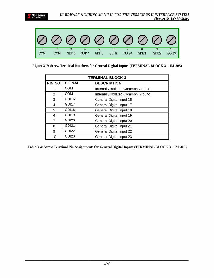
HARDWARE & WIRING MANUAL FOR THE VERSIOBUS II INTERFACE SYSTEM
Chapter 3: I/O Modules
_____________________________________________________________________________________
3-7
Figure 3-7: Screw Terminal Numbers for General Digital Inputs (TERMINAL BLOCK 3 – IM-305)
Table 3-4: Screw Terminal Pin Assignments for General Digital Inputs (TERMINAL BLOCK 3 – IM-305)
TERMINAL BLOCK 3
PIN NO. SIGNAL DESCRIPTION
1 COM Internally Isolated Common Ground
2 COM Internally Isolated Common Ground
3 GDI16 General Digital Input 16
4 GDI17 General Digital Input 17
5 GDI18 General Digital Input 18
6 GDI19 General Digital Input 19
7 GDI20 General Digital Input 20
8 GDI21 General Digital Input 21
9 GDI22 General Digital Input 22
10 GDI23 General Digital Input 23
1 COM
2 COM
3 GDI16
4 GDI17
5 GDI18
6 GDI19
7 GDI20
8 GDI21
9 GDI22
10 GDI23

HARDWARE & WIRING MANUAL FOR THE VERSIOBUS II INTERFACE SYSTEM
Chapter 3: I/O Modules
_____________________________________________________________________________________
3-8
Figure 3-8: Screw Terminal Numbers for General Digital Inputs (TERMINAL BLOCK 4 – IM-305)
Table 3-5: Screw Terminal Pin Assignments for General Digital Inputs (TERMINAL BLOCK 4 – IM-305)
TERMINAL BLOCK 4
PIN NO. SIGNAL DESCRIPTION
1 COM Internally Isolated Common Ground
2 COM Internally Isolated Common Ground
3 GDI24 General Digital Input 24
4 GDI25 General Digital Input 25
5 GDI26 General Digital Input 26
6 GDI27 General Digital Input 27
7 GDI28 General Digital Input 28
8 GDI29 General Digital Input 29
9 GDI30 General Digital Input 30
10 GDI31 General Digital Input 31
1 COM
2 COM
3 GDI24
4 GDI25
5 GDI26
6 GDI27
7 GDI28
8 GDI29
9 GDI30
10 GDI31
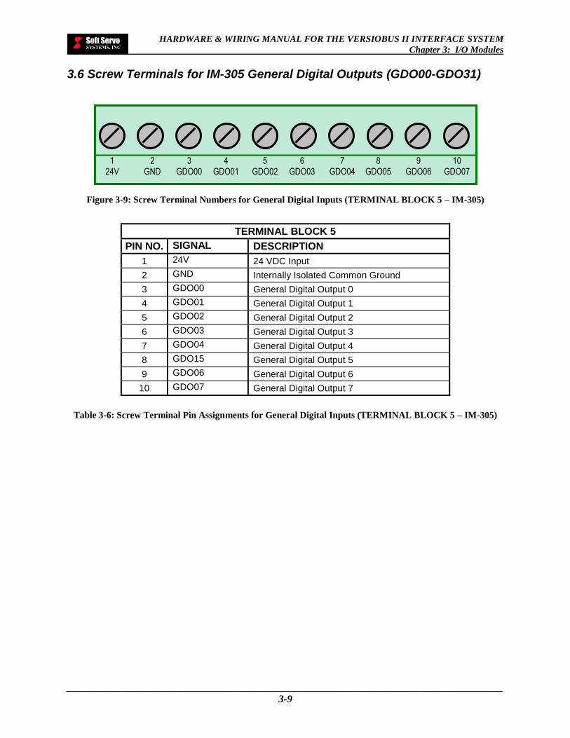
HARDWARE & WIRING MANUAL FOR THE VERSIOBUS II INTERFACE SYSTEM
Chapter 3: I/O Modules
_____________________________________________________________________________________
3-9
3.6 Screw Terminals for IM-305 General Digital Outputs (GDO00-GDO31)
Figure 3-9: Screw Terminal Numbers for General Digital Inputs (TERMINAL BLOCK 5 – IM-305)
Table 3-6: Screw Terminal Pin Assignments for General Digital Inputs (TERMINAL BLOCK 5 – IM-305)
TERMINAL BLOCK 5
PIN NO. SIGNAL DESCRIPTION
1 24V 24 VDC Input
2 GND Internally Isolated Common Ground
3 GDO00 General Digital Output 0
4 GDO01 General Digital Output 1
5 GDO02 General Digital Output 2
6 GDO03 General Digital Output 3
7 GDO04 General Digital Output 4
8 GDO15 General Digital Output 5
9 GDO06 General Digital Output 6
10 GDO07 General Digital Output 7
1 24V
2 GND
3 GDO00
4 GDO01
5 GDO02
6 GDO03
7 GDO04
8 GDO05
9 GDO06
10 GDO07

HARDWARE & WIRING MANUAL FOR THE VERSIOBUS II INTERFACE SYSTEM
Chapter 3: I/O Modules
_____________________________________________________________________________________
3-10
Figure 3-10: Screw Terminal Numbers for General Digital Inputs (TERMINAL BLOCK 6 – IM-305)
Table 3-7: Screw Terminal Pin Assignments for General Digital Inputs (TERMINAL BLOCK 6 – IM-305)
TERMINAL BLOCK 6
PIN NO. SIGNAL DESCRIPTION
1 24V 24 VDC Input
2 GND Internally Isolated Common Ground
3 GDO08 General Digital Output 8
4 GDO09 General Digital Output 9
5 GDO10 General Digital Output 10
6 GDO11 General Digital Output 11
7 GDO12 General Digital Output 12
8 GDO13 General Digital Output 13
9 GDO14 General Digital Output 14
10 GDO15 General Digital Output 15
1 24V
2 GND
3 GDO08
4 GDO09
5 GDO10
6 GDO11
7 GDO12
8 GDO13
9 GDO14
10 GDO15

HARDWARE & WIRING MANUAL FOR THE VERSIOBUS II INTERFACE SYSTEM
Chapter 3: I/O Modules
_____________________________________________________________________________________
3-11
Figure 3-11: Screw Terminal Numbers for General Digital Inputs (TERMINAL BLOCK 7 – IM-305)
Table 3-8: Screw Terminal Pin Assignments for General Digital Inputs (TERMINAL BLOCK 7 – IM-305)
TERMINAL BLOCK 7
PIN NO. SIGNAL DESCRIPTION
1 24V 24 VDC Input
2 GND Internally Isolated Common Ground
3 GDO16 General Digital Output 16
4 GDO17 General Digital Output 17
5 GDO18 General Digital Output 18
6 GDO19 General Digital Output 19
7 GDO20 General Digital Output 20
8 GDO21 General Digital Output 21
9 GDO22 General Digital Output 22
10 GDO23 General Digital Output 23
1
24V
2
GND
3
GDO16
4
GDO17
5
GDO18
6
GDO19
7
GDO20
8
GDO21
9
GDO22
10
GDO23

HARDWARE & WIRING MANUAL FOR THE VERSIOBUS II INTERFACE SYSTEM
Chapter 3: I/O Modules
_____________________________________________________________________________________
3-12
Figure 3-12: Screw Terminal Numbers for General Digital Inputs (TERMINAL BLOCK 8 – IM-305)
Table 3-9: Screw Terminal Pin Assignments for General Digital Inputs (TERMINAL BLOCK 8 – IM-305)
TERMINAL BLOCK 8
PIN NO. SIGNAL DESCRIPTION
1 24V 24 VDC Input
2 GND Internally Isolated Common Ground
3 GDO24 General Digital Output 24
4 GDO25 General Digital Output 25
5 GDO26 General Digital Output 26
6 GDO27 General Digital Output 27
7 GDO28 General Digital Output 28
8 GDO29 General Digital Output 29
9 GDO30 General Digital Output 30
10 GDO31 General Digital Output 31
1 24V
2 GND
3 GDO24
4 GDO25
5 GDO26
6 GDO27
7 GDO28
8 GDO29
9 GDO30
10 GDO31
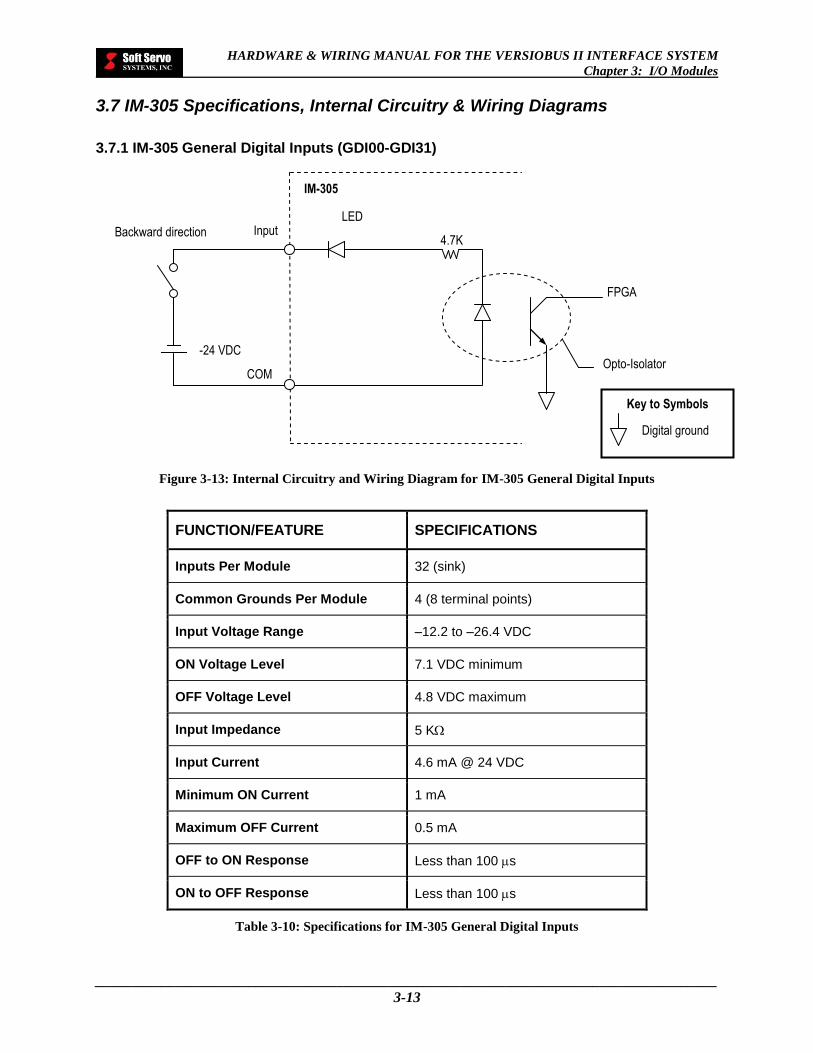
HARDWARE & WIRING MANUAL FOR THE VERSIOBUS II INTERFACE SYSTEM
Chapter 3: I/O Modules
_____________________________________________________________________________________
3-13
3.7 IM-305 Specifications, Internal Circuitry & Wiring Diagrams
3.7.1 IM-305 General Digital Inputs (GDI00-GDI31)
Figure 3-13: Internal Circuitry and Wiring Diagram for IM-305 General Digital Inputs
FUNCTION/FEATURE SPECIFICATIONS
Inputs Per Module 32 (sink)
Common Grounds Per Module 4 (8 terminal points)
Input Voltage Range –12.2 to –26.4 VDC
ON Voltage Level 7.1 VDC minimum
OFF Voltage Level 4.8 VDC maximum
Input Impedance 5 K
Input Current 4.6 mA @ 24 VDC
Minimum ON Current 1 mA
Maximum OFF Current 0.5 mA
OFF to ON Response Less than 100 s
ON to OFF Response Less than 100 s
Table 3-10: Specifications for IM-305 General Digital Inputs
COM
Input
FPGA
-24 VDC Opto-Isolator
Backward direction
IM-305
Key to Symbols
Digital ground
4.7K
LED

HARDWARE & WIRING MANUAL FOR THE VERSIOBUS II INTERFACE SYSTEM
Chapter 3: I/O Modules
_____________________________________________________________________________________
3-14
3.7.2 IM-305 General Digital Outputs (GDO00-GDO31)
Figure 3-14: Internal Circuitry and Wiring Diagram for IM-305 General Digital Outputs
NOTE: If the load is a solenoid or a coil of an electromagnetic / mechanical relay, a high-speed fly-back diode must be installed across the load with the cathode end
connected to VIN.
Load (DC Coil Relay)
Output
High-Speed Fly-
Back Diode
VIN
Key to Symbols
Digital ground
COM
Output Load
24 VDC
Opto-Isolator
IM-305
3.3V
FPGA
4.7K LED 24V input

HARDWARE & WIRING MANUAL FOR THE VERSIOBUS II INTERFACE SYSTEM
Chapter 3: I/O Modules
_____________________________________________________________________________________
3-15
FUNCTION/FEATURE SPECIFICATIONS
Outputs Per Module 32 (sink)
Common Grounds Per Module 4
Operating Range 10.8 to 26.4 VDC or –10.8 to –26.4 VDC
Type Darlington
Peak Voltage 300 VDC
ON Voltage Drop 1.2 VDC maximum
Maximum Load Current 120 mA per point 960 mA per common
Maximum Leakage Current 0.1 mA
External DC Required 24 VDC ±10%, 200 mA maximum
OFF to ON Response Less than 100 s
ON to OFF Response Less than 100 s
Table 3-11: Specifications for IM-305 General Digital Outputs

HARDWARE & WIRING MANUAL FOR THE VERSIOBUS II INTERFACE SYSTEM
Chapter 4: Breakout Boxes
_____________________________________________________________________________________
4-1
Chapter 4: Breakout Boxes
4.1 Breakout Boxes – Descriptions
TB36A: 36-pin screw terminal module (for the DC-155) with two terminal blocks for spade terminals
TB36B: Compact 36-pin screw terminal module (for the DC-155) with a single terminal block for wire entry screw
terminals
TB37BD: 37-pin screw terminal module (for making connections between the operator’s panel and the PC) with a
single terminal block for wire entry screw terminals
TB36A TB36B TB37BD
Figure 4-1: Photos of TB36A, TB36B and TB37BD Breakout Boxes
4.2 TB36A / TB36B / TB37BD Functional Specifications
FUNCTION/FEATURE SPECIFICATIONS
Screw Terminals TB36A: 2 terminal blocks, 18 screw terminals each TB36B: 1 terminal block, 36 screw terminals TB37BD: 1 terminal block, 37 screw terminals
Mounting DIN Rail
Dimensions TB36A: 93 mm x 80 mm x 56 mm deep TB36B: 93 mm x 80 mm x 50 mm deep TB37BD: 77 mm x 102 mm x 57 mm deep
Table 4-1: Functional Specifications for TB36A, TB36B and TB37BD Breakout Boxes

HARDWARE & WIRING MANUAL FOR THE VERSIOBUS II INTERFACE SYSTEM
Chapter 4: Breakout Boxes
_____________________________________________________________________________________
4-2
4.3 TB36A Terminal Number Assignments
Figure 4-2: TB36A Breakout Box Terminal Number Assignments
4.4 TB36A Terminal Number Assignments for When TB36A Is Connected to the DC-155 Axis Connector
TERMINAL BLOCK 1
TERMINAL BLOCK 2
Figure 4-3: TB36A Terminal Number Assignments for When TB36A Is Connected to DC-155 Axis Connector
NOTE: The pin assignments for the 36-pin connector are not the same as the pin
numbers for the 36 screw terminals. In other words, screw terminal #1 does not
connect to pin #1. See the terminal number pin assignments for the TB36A and the
TB36B later in this chapter.
CAUTION !
36-pin MDR connector
Terminal Block 1
1 3 5 7 9 11 13 15 17
2 4 6 8 10 12 14 16 18
1 3 5 7 9 11 13 15 17
2 4 6 8 10 12 14 16 18
Terminal Block 2
80 m
m
93 mm
1 18
19 36
1 VOUT
3 GND
5 RST
7 SC1
9 SC3
11 FAULT
13 SS1
15 SS3
17 ADC(1-4)
2 GND
4 SVON
6 SC0
8 SC2
10 GND
12 SS0
14 SS2
16 GND
18 AGND
1 A_OUT
3 VBAT(+)
5 E_A_H
7 E_B_H
9 E_Z_H
11 E_S_H
13 +5V
15 PLS_H
17 DIR_H
2 AGND
4 SG
6 E_A_L
8 E_B_L
10 E_Z_L
12 E_S_L
14 16 PLS_L
18 DIR_L

HARDWARE & WIRING MANUAL FOR THE VERSIOBUS II INTERFACE SYSTEM
Chapter 4: Breakout Boxes
_____________________________________________________________________________________
4-3
4.5 TB36A Terminal Number Assignments for When TB36A Is Connected to the DC-155 I/O 1 Connector
TERMINAL BLOCK 1
TERMINAL BLOCK 2
Figure 4-4: TB36A Terminal Number Assignments for When TB36A Is Connected to the DC-155 I/O 1
Connector
4.6 TB36A Terminal Number Assignments for When TB36A Is Connected to the DC-155 I/O 2 Connector
TERMINAL BLOCK 1
TERMINAL BLOCK 2
Figure 4-5: TB36A Terminal Number Assignments for When TB36A Is Connected to the DC-155 I/O 2
Connector
1 GND
3 NLS2
5 GND
7 NLS3
9 COM0
11 DI9
13 DI11
15 DI13
17 DI15
2 HS2
4 PLS2
6 HS3
8 PLS3
10 DI8
12 DI10
14 DI12
16 DI14
18 COM0
1 ADC7
3 ADC8
5 7 COM2
9 DO9
11 DO11
13 DO12
15 DO14
17 COM2
2 AGND
4 AGND
6 COM2
8 DO8
10 DO10
12 COM2
14 DO13
16 DO15
18 COM2
1 GND
3 NLS0
5 GND
7 NLS1
9 COM0
11 DI1
13 DI3
15 DI5
17 DI7
2 HS0
4 PLS0
6 HS1
8 PLS1
10 DI0
12 DI2
14 DI4
16 DI6
18 COM0
1 ADC5
3 ADC6
5
7 COM1
9 DO1
11 DO3
13 DO4
15 DO6
17 COM1
2 AGND
4 AGND
6 COM1
8 DO0
10 DO2
12 COM1
14 DO5
16 DO7
18 COM1

HARDWARE & WIRING MANUAL FOR THE VERSIOBUS II INTERFACE SYSTEM
Chapter 4: Breakout Boxes
_____________________________________________________________________________________
4-4
4.7 TB36B Terminal Number Assignments
Figure 4-6: TB36B Breakout Box Terminal Number Assignments
NOTE: The pin assignments for the 36-pin connector are the same as the pin
numbers for the 36 screw terminals. In other words, screw terminal #1 connects to
pin #1.
CAUTION !
36-pin MDR connector
18 16 2 30 24 12
33 23 11 17 5 9
6 4
1 3 7 13 15 19 21 25 27 31 29 35
8 10 14 20 22 26 28 32 34 36
7 13 10 3 2 16 14 18 17 15 12 11 9 8 6 5 4 1
28 29 36 22 25 31 34 35 33 32 30 27 26 24 23 21 20 19
80 m
m
93 mm
1 18
19 36

HARDWARE & WIRING MANUAL FOR THE VERSIOBUS II INTERFACE SYSTEM
Chapter 4: Breakout Boxes
_____________________________________________________________________________________
4-5
4.8 TB36B Terminal Number Assignments for When the TB36B is Connected to the DC-155 Axis, I/O 1 & I/O 2 Connectors
Figure 4-7: TB36B Terminal Number Assignments
18
A_O
UT
17
VB
AT(
+)
16
E_A
_H
15
E_B
_H
14
E_Z
_H
13
E_S
_H
12
+5V
11
PLS
_H
10
DIR
_H
36
AG
ND
35
SG
34
E_A
_L
33
E_B
_L
32
E_Z
_L
31
E_S
_L
30
29
PLS
_L
28
DIR
_L
9
VO
UT
8
GN
D
7
RS
T
6
SC
1
5
SC
3
4
FA
ULT
3
SS
1
2
SS
3
1
ADC
(1-4
)
27
GN
D
26
SV
ON
25
SC
0
24
SC
2
23
GN
D
22
SS
0
21
SS
2 2
0
GN
D
19
AG
ND
18
GN
D
17
NLS
0
16
GN
D
15
NLS
1
14
CO
M0
13
DI1
12
DI3
11
DI5
10
DI7
36
HS
0
35
PLS
0
34
HS
1
33
PLS
1
32
DI0
31
DI2
30
DI4
2
9
DI6
28
CO
M0
9
AD
C5
8
AD
C6
7
6
CO
M1
5
DO
1
4
DO
3
3
DO
4
2
DO
6
1
CO
M1
27
AG
ND
26
AG
ND
25
CO
M1
24
DO
0
23
DO
2
22
CO
M1
21
DO
5 2
0
DO
7
19
CO
M1
18
GN
D
17
NLS
2
16
GN
D
15
NLS
3
14
CO
M0
13
DI9
12
DI1
1
11
DI1
3
10
DI1
5
36
HS
2
35
PLS
2
34
HS
3
33
PLS
3
32
DI8
31
DI1
0
30
DI1
2 2
9
DI1
4
28
CO
M0
9
AD
C7
8
AD
C8
7
6
CO
M2
5
DO
9
4
DO
11
3
DO
12
2
DO
14
1
CO
M2
27
AG
ND
26
AG
ND
25
CO
M2
24
DO
8
23
DO
10
22
CO
M2
21
DO
13
20
DO
15
19
CO
M2
DC
-155 A
XIS
CO
NN
EC
TO
R
DC
-155
I/O
1 C
ON
NE
CT
OR
DC
-155
I/O
2 C
ON
NE
CT
OR
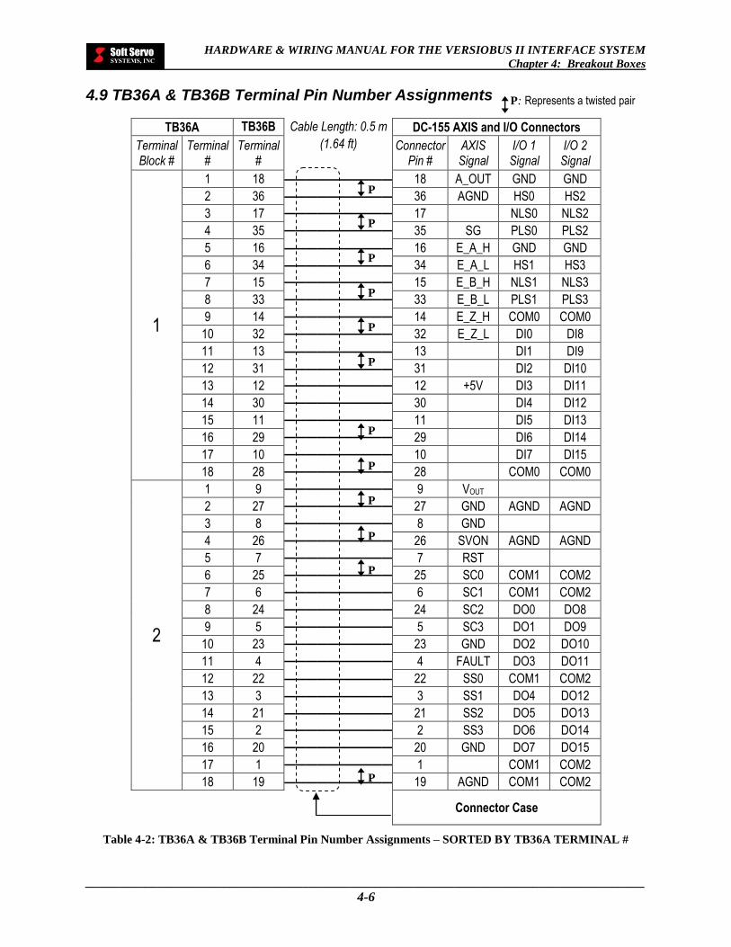
HARDWARE & WIRING MANUAL FOR THE VERSIOBUS II INTERFACE SYSTEM
Chapter 4: Breakout Boxes
_____________________________________________________________________________________
4-6
4.9 TB36A & TB36B Terminal Pin Number Assignments
TB36A TB36B Cable Length: 0.5 m (1.64 ft)
DC-155 AXIS and I/O Connectors
Terminal Block #
Terminal #
Terminal #
(1.64 ft) Connector Pin #
AXIS Signal
I/O 1 Signal
I/O 2 Signal
1
1 18 —————————— 18 A_OUT GND GND
2 36 —————————— 36 AGND HS0 HS2
3 17 ————————————————
17 NLS0 NLS2
4 35 ——————————————
35 SG PLS0 PLS2
5 16 —————————— 16 E_A_H GND GND
6 34 —————————— 34 E_A_L HS1 HS3
7 15 ——————————————
15 E_B_H NLS1 NLS3
8 33 ——————————————
33 E_B_L PLS1 PLS3
9 14 ——————————————
14 E_Z_H COM0 COM0
10 32 ——————————————
32 E_Z_L DI0 DI8
11 13 —————————— 13 DI1 DI9
12 31 —————————— 31 DI2 DI10
13 12 ——————————————
12 +5V DI3 DI11
14 30 ——————————————
30 DI4 DI12
15 11 ——————————————
11 DI5 DI13
16 29 ——————————————
29 DI6 DI14
17 10 ——————————————
10 DI7 DI15
18 28 ——————————————
28 COM0 COM0
2
1 9 ——————————————
9 VOUT ADC5 ADC7
2 27 ——————————————
27 GND AGND AGND
3 8 ——————————————
8 GND ADC6 ADC8
4 26 ——————————————
26 SVON AGND AGND
5 7 ——————————————
7 RST
6 25 ——————————————
25 SC0 COM1 COM2
7 6 ——————————————
6 SC1 COM1 COM2
8 24 ——————————————
24 SC2 DO0 DO8
9 5 ——————————————
5 SC3 DO1 DO9
10 23 ——————————————
23 GND DO2 DO10
11 4 ——————————————
4 FAULT DO3 DO11
12 22 —————————— 22 SS0 COM1 COM2
13 3 —————————— 3 SS1 DO4 DO12
14 21 —————————— 21 SS2 DO5 DO13
15 2 ——————————————
2 SS3 DO6 DO14
16 20 ——————————————
20 GND DO7 DO15
17 1 ——————————————
1 ADC(1-4) COM1 COM2
18 19 —————————— 19 AGND COM1 COM2
Connector Case
Table 4-2: TB36A & TB36B Terminal Pin Number Assignments – SORTED BY TB36A TERMINAL #
P: Represents a twisted pair
P
P
P
P
P
P
P
P
P
P
P
P

HARDWARE & WIRING MANUAL FOR THE VERSIOBUS II INTERFACE SYSTEM
Chapter 4: Breakout Boxes
_____________________________________________________________________________________
4-7
TB36A TB36B Cable Length: 0.5 m (1.64 ft)
DC-155 AXIS and I/O Connectors
Terminal Block #
Terminal #
Terminal #
(1.64 ft) Connector Pin #
AXIS Signal
I/O 1 Signal
I/O 2 Signal
2 17 1 ——————————————
1 ADC(1-4) COM1 COM2
2 15 2 ——————————————
2 SS3 DO6 DO14
2 13 3 —————————— 3 SS1 DO4 DO12
2 11 4 ——————————————
4 FAULT DO3 DO11
2 9 5 ——————————————
5 SC3 DO1 DO9
2 7 6 ——————————————
6 SC1 COM1 COM2
2 5 7 ——————————————
7 RST
2 3 8 ——————————————
8 GND ADC6 ADC8
2 1 9 ——————————————
9 VOUT ADC5 ADC7
1 17 10 ——————————————
10 DI7 DI15
1 15 11 ——————————————
11 DI5 DI13
1 13 12 ——————————————
12 +5V DI3 DI11
1 11 13 —————————— 13 DI1 DI9
1 9 14 ——————————————
14 E_Z_H COM0 COM0
1 7 15 ——————————————
15 E_B_H NLS1 NLS3
1 5 16 —————————— 16 E_A_H GND GND
1 3 17 ————————————————
17 NLS0 NLS2
1 11 11 1 1
1 18 —————————— 18 A_OUT GND GND
2 18 19 —————————— 19 AGND COM1 COM2
2 16 20 ——————————————
20 GND DO7 DO15
2 14 21 —————————— 21 SS2 DO5 DO13
2 12 22 —————————— 22 SS0 COM1 COM2
2 10 23 ——————————————
23 GND DO2 DO10
2 8 24 ——————————————
24 SC2 DO0 DO8
2 6 25 ——————————————
25 SC0 COM1 COM2
2 4 26 ——————————————
26 SVON AGND AGND
2 2 27 ——————————————
27 GND AGND AGND
1 18 28 ——————————————
28 COM0 COM0
1 16 29 ——————————————
29 DI6 DI14
1 14 30 ——————————————
30 DI4 DI12
1 12 31 —————————— 31 DI2 DI10
1 10 32 ——————————————
32 E_Z_L DI0 DI8
1 8 33 ——————————————
33 E_B_L PLS1 PLS3
1 6 34 —————————— 34 E_A_L HS1 HS3
1 4 35 ——————————————
35 SG PLS0 PLS2
1 2 36 —————————— 36 AGND HS0 HS2
Connector Case
Table 4-3: TB36A & TB36B Terminal Pin Number Assignments – SORTED BY CONNECTOR PIN #
NOTE: twisted pairs not shown.
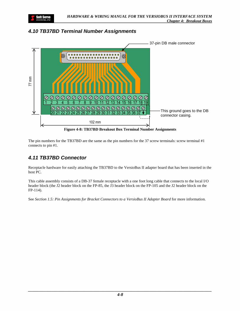
HARDWARE & WIRING MANUAL FOR THE VERSIOBUS II INTERFACE SYSTEM
Chapter 4: Breakout Boxes
_____________________________________________________________________________________
4-8
4.10 TB37BD Terminal Number Assignments
Figure 4-8: TB37BD Breakout Box Terminal Number Assignments
The pin numbers for the TB37BD are the same as the pin numbers for the 37 screw terminals: screw terminal #1
connects to pin #1.
4.11 TB37BD Connector
Receptacle hardware for easily attaching the TB37BD to the VersioBus II adapter board that has been inserted in the
host PC.
This cable assembly consists of a DB-37 female receptacle with a one foot long cable that connects to the local I/O
header block (the J2 header block on the FP-85, the J3 header block on the FP-105 and the J2 header block on the
FP-114).
See Section 1.5: Pin Assignments for Bracket Connectors to a VersioBus II Adapter Board for more information.
37 31 25 28 22 24 20 21 23 26 27 29 30 32 33 35 34 36
18 12 6 9 3 5 1 2 4 7 8 10 11 13 14 16 15 19 17
37-pin DB male connector
This ground goes to the DB connector casing.
77 m
m
102 mm

HARDWARE & WIRING MANUAL FOR THE VERSIOBUS II INTERFACE SYSTEM
Chapter 4: Breakout Boxes
_____________________________________________________________________________________
4-9
4.12 TB37BD Terminal Pin Number Assignments
Table 4-4: TB37BD Terminal Pin Number Assignments
NOTES:
COM1 is for outputs 0 – 7 (pins 11 – 14 and 29 – 32).
COM2 is for outputs 8 – 15 (pins 16 – 19 and 34 – 37).
PIN NO. SIGNAL PIN NO. SIGNAL
1 IN0 20 IN1
2 IN2 21 IN3
3 IN4 22 IN5
4 IN6 23 IN7
5 COM0_GND (for inputs) 24 IN8
6 IN9 25 IN10
7 IN11 26 IN12
8 IN13 27 IN14
9 IN15 28 NC
10 COM1_GND (for outputs 0 – 7, pins 11 – 14 & 29 – 32)
29 OUT0
11 OUT1 30 OUT2
12 OUT3 31 OUT4
13 OUT5 32 OUT6
14 OUT7 33 NC
15 COM2_GND (for outputs 8 – 15, pins 16 – 19 & 34 – 37)
34 OUT8
16 OUT9 35 OUT10
17 OUT11 36 OUT12
18 OUT13 37 OUT14
19 OUT15

HARDWARE & WIRING MANUAL FOR THE VERSIOBUS II INTERFACE SYSTEM
Chapter 5: HW-200 Handwheel
_____________________________________________________________________________________
5-1
Chapter 5: HW-200 Handwheel
5.1 HW-200 Description
HW-200: Handwheel pulse generator with an Axis Selection Switch, a Multiplier Selection Switch, a Handwheel
Dial and an Emergency Stop Button.
Figure 5-1: Photo of HW-200 Handwheel
5.2 HW-200 Functional Specifications
FUNCTION/FEATURE SPECIFICATIONS
Axis Selection Switch Axes X, Y, Z, 4, 5
Multiplier Selection Switch X1, X10, X100, X1000
Emergency Stop Button E-STOP switch with RESET
Dimensions 163 mm x 70 mm x 63 mm deep
Table 5-1: HW-200 Functional Specifications
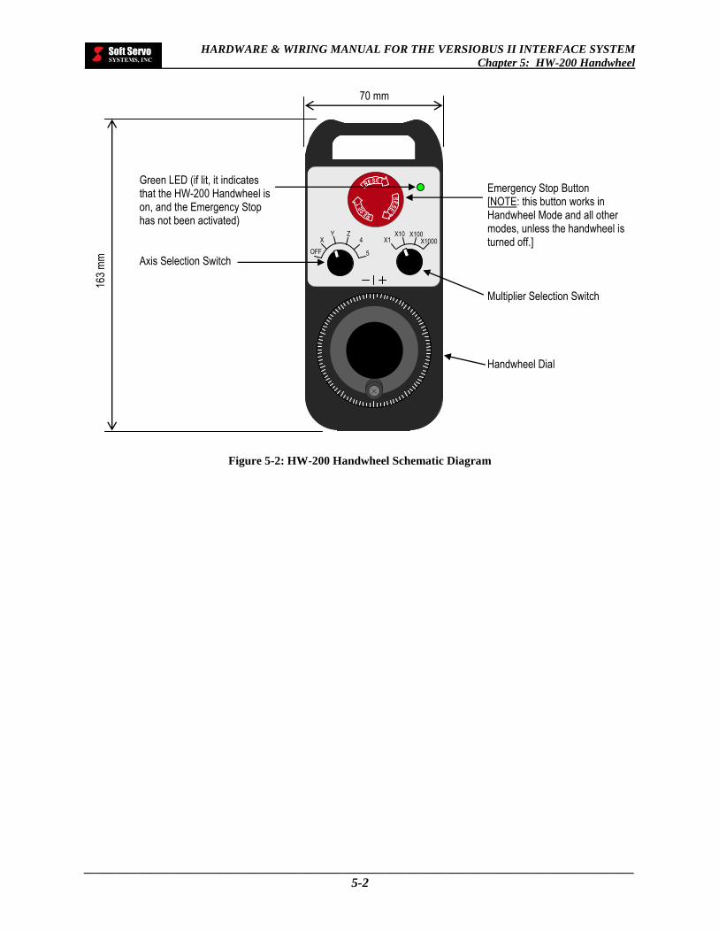
HARDWARE & WIRING MANUAL FOR THE VERSIOBUS II INTERFACE SYSTEM
Chapter 5: HW-200 Handwheel
_____________________________________________________________________________________
5-2
Figure 5-2: HW-200 Handwheel Schematic Diagram
OFF
X Y Z
4
5
X1 X10 X100
X1000
Green LED (if lit, it indicates that the HW-200 Handwheel is on, and the Emergency Stop has not been activated) Axis Selection Switch
Emergency Stop Button [NOTE: this button works in Handwheel Mode and all other modes, unless the handwheel is turned off.] Multiplier Selection Switch
Handwheel Dial
163
mm
70 mm

HARDWARE & WIRING MANUAL FOR THE VERSIOBUS II INTERFACE SYSTEM
Chapter 5: HW-200 Handwheel
_____________________________________________________________________________________
5-3
For use with an off-the-shelf PC, the HW-200 is shipped with a flat cable attached to its cord. The flat cable
connects to the J1 header block on the FP-85, the J1 header block on the FP-105 or the J1 header block on the FP-
114, via a handwheel/handwheel E-STOP connector, as shown:
Figure 5-3: Connection of the HW-200 Handwheel to a VersioBus II Adapter Board
OFF
X Y Z
4
5
X1 X10 X100
X1000
25 26 1 2
39 40 1
2
Soft Servo Systems
Inc.
Waltham, MA 02451
FP-75 INTERFACE BOARD
ASSY NO.0203
REV-
SER NO

HARDWARE & WIRING MANUAL FOR THE VERSIOBUS II INTERFACE SYSTEM
Chapter 5: HW-200 Handwheel
_____________________________________________________________________________________
5-4
5.3 HW-200 Pin Assignments for the 25-Pin DB Handwheel Connectors
Table 5-2: HW-200 Pin Assignments for the 25-Pin DB Handwheel Connectors
PIN NO. NAME SIGNAL
1 A_LO Encoder Signal A, Low Side
2 GND Digital Ground
3 B_HI Encoder Signal B, High Side
4 DIF_SEL Encoder Input Select
5 X10 X10
6 X1000 X1000
7 X-Axis Axis X
8 Z-Axis Axis Z
9 5-Axis Axis 5
10 Vcc Vcc (5V)
11 E-STOP-B-1 Handwheel E-STOP button connection 1
12 E-STOP-B-2 Handwheel E-STOP button connection 2
13 E-STOP-B-2 Handwheel E-STOP button connection 2
14 A_HI Encoder Signal A, High Side
15 B_LO Encoder Signal B, Low Side
16 GND Digital Ground
17 X1 X1
18 X100 X100
19 E-STOP LOGIC E-STOP
20 Y-Axis Axis Y
21 4-Axis Axis 4
22 Vcc Vcc (5V)
23 E-STOP-B-1 Handwheel E-STOP button connection 1
24 E-STOP-B-1 Handwheel E-STOP button connection 1
25 E-STOP-B-2 Handwheel E-STOP button connection 2
Male 25-Pin DB HW-100 Connector
of the HW-100 Cord
25 14
13 1

HARDWARE & WIRING MANUAL FOR THE VERSIOBUS II INTERFACE SYSTEM
Chapter 5: HW-200 Handwheel
_____________________________________________________________________________________
5-5
5.4 HW-200 Wiring Diagrams
5.4.1 E-STOP / Handwheel Connections
Figure 5-4: Wiring Diagram for E-STOP/Handwheel Connection
2 MCC Switch Port
1
DB-25M Connector of the
HW-200 Cord
23 14
12 1
25 24
13 11
Half of Handwheel
E-STOP Switch E-STOP-B-2
E-STOP-B-1
NOTE: Soft Servo Systems does not offer an MCC switch port with connections to the DB-25M connector of the HW-200 handwheel cord. This diagram is intended to show a recommended
connection that could be made by a user.

HARDWARE & WIRING MANUAL FOR THE VERSIOBUS II INTERFACE SYSTEM
Chapter 6: HW-100 Handwheel
_____________________________________________________________________________________
6-1
Chapter 6: HW-100 Handwheel
6.1 HW-100 Description
HW-100: Handwheel pulse generator with an Axis Selection Switch, a Multiplier Selection Switch, a Handwheel
Dial and an Emergency Stop Button.
NOTE: The HW-100 Handwheel has been discontinued and replaced by the HW-200 Handwheel. Please see
Chapter 5: HW-200 Handwheel for more information regarding the HW-200 Handwheel.
Figure 6-1: Photo of HW-100 Handwheel
6.2 HW-100 Functional Specifications
FUNCTION/FEATURE SPECIFICATIONS
Axis Selection Switch Axes X, Y, Z, 4, 5
Multiplier Selection Switch X1, X10, X100, X1000
Emergency Stop Button E-STOP switch with RESET
Dimensions 170 mm x 79 mm x 69 mm deep
Table 6-1: HW-100 Functional Specifications

HARDWARE & WIRING MANUAL FOR THE VERSIOBUS II INTERFACE SYSTEM
Chapter 6: HW-100 Handwheel
_____________________________________________________________________________________
6-2
Figure 6-2: HW-100 Handwheel Schematic Diagram
Axis Selection Switch Green LED (if lit, it indicates that the HW-100 Handwheel is on, and the Emergency Stop
has not been activated)
Emergency Stop Button [NOTE: this button works in Handwheel Mode and all other modes, unless the handwheel is turned off.] Multiplier Selection Switch Handwheel Dial
170
mm
79 mm
SOFT
SERVO
SYSTEMS
X1 X10 X100
X1000 Y
OFF
X Z
4
5

HARDWARE & WIRING MANUAL FOR THE VERSIOBUS II INTERFACE SYSTEM
Chapter 6: HW-100 Handwheel
_____________________________________________________________________________________
6-3
For use with an off-the-shelf PC, the HW-100 is shipped with a flat cable attached to its cord. The flat cable
connects to the J1 header block on the FP-85, the J1 header block on the FP-105 or the J1 header block on the FP-
114, via a handwheel/handwheel E-STOP connector, as shown:
Figure 6-3: Connection of the HW-100 Handwheel to a VersioBus II Adapter Board
Y
OFF
X Z
4
5
SOFT
SERVO
SYSTEMS
X1 X10 X100
X1000
25 26 1 2
39 40 1
2
Soft Servo Systems
Inc.
Waltham, MA 02451
FP-75 INTERFACE BOARD
ASSY NO.0203
REV-
SER NO

HARDWARE & WIRING MANUAL FOR THE VERSIOBUS II INTERFACE SYSTEM
Chapter 6: HW-100 Handwheel
_____________________________________________________________________________________
6-4
6.3 HW-100 Pin Assignments for the 25-Pin DB Handwheel Connectors
Table 6-2: HW-100 Pin Assignments for the 25-Pin DB Handwheel Connectors
PIN NO. NAME SIGNAL
1 A_LO Encoder Signal A, Low Side
2 GND Digital Ground
3 B_HI Encoder Signal B, High Side
4 DIF_SEL Encoder Input Select
5 X10 X10
6 X1000 X1000 (Optional)
7 X-Axis Axis X
8 Z-Axis Axis Z
9 5-Axis Axis 5 (Optional)
10 Vcc Vcc (5V)
11 E-STOP-B-1 Handwheel E-STOP button connection 1
12 E-STOP-B-2 Handwheel E-STOP button connection 2
13 E-STOP-B-2 Handwheel E-STOP button connection 2
14 A_HI Encoder Signal A, High Side
15 B_LO Encoder Signal B, Low Side
16 GND Digital Ground
17 X1 X1
18 X100 X100
19 E-STOP LOGIC E-STOP
20 Y-Axis Axis Y
21 4-Axis Axis 4
22 Vcc Vcc (5V)
23 E-STOP-B-1 Handwheel E-STOP button connection 1
24 E-STOP-B-1 Handwheel E-STOP button connection 1
25 E-STOP-B-2 Handwheel E-STOP button connection 2
Male 25-Pin DB HW-100 Connector
of the HW-100 Cord
25 14
13 1
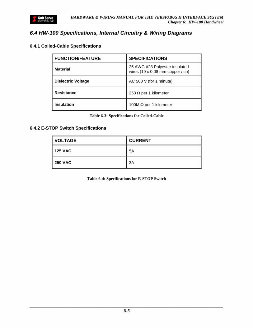
HARDWARE & WIRING MANUAL FOR THE VERSIOBUS II INTERFACE SYSTEM
Chapter 6: HW-100 Handwheel
_____________________________________________________________________________________
6-5
6.4 HW-100 Specifications, Internal Circuitry & Wiring Diagrams
6.4.1 Coiled-Cable Specifications
FUNCTION/FEATURE SPECIFICATIONS
Material 25 AWG #28 Polyester insulated wires (19 x 0.08 mm copper / tin)
Dielectric Voltage AC 500 V (for 1 minute)
Resistance 253 per 1 kilometer
Insulation 100M per 1 kilometer
Table 6-3: Specifications for Coiled-Cable
6.4.2 E-STOP Switch Specifications
VOLTAGE CURRENT
125 VAC 5A
250 VAC 3A
Table 6-4: Specifications for E-STOP Switch
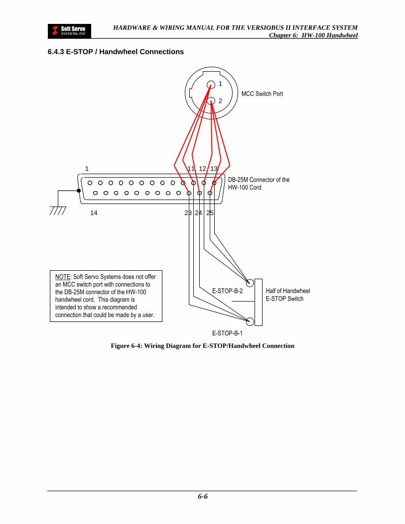
HARDWARE & WIRING MANUAL FOR THE VERSIOBUS II INTERFACE SYSTEM
Chapter 6: HW-100 Handwheel
_____________________________________________________________________________________
6-6
6.4.3 E-STOP / Handwheel Connections
Figure 6-4: Wiring Diagram for E-STOP/Handwheel Connection
2 MCC Switch Port
1
DB-25M Connector of the HW-100 Cord
23 14
12 1
25 24
13 11
Half of Handwheel
E-STOP Switch E-STOP-B-2
E-STOP-B-1
NOTE: Soft Servo Systems does not offer an MCC switch port with connections to the DB-25M connector of the HW-100 handwheel cord. This diagram is intended to show a recommended connection that could be made by a user.
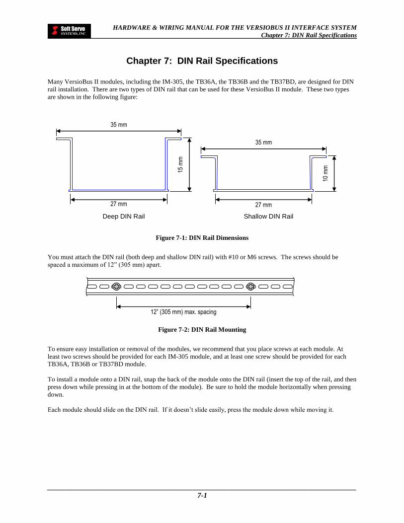
HARDWARE & WIRING MANUAL FOR THE VERSIOBUS II INTERFACE SYSTEM
Chapter 7: DIN Rail Specifications
_____________________________________________________________________________________
7-1
Chapter 7: DIN Rail Specifications
Many VersioBus II modules, including the IM-305, the TB36A, the TB36B and the TB37BD, are designed for DIN
rail installation. There are two types of DIN rail that can be used for these VersioBus II module. These two types
are shown in the following figure:
Figure 7-1: DIN Rail Dimensions
You must attach the DIN rail (both deep and shallow DIN rail) with #10 or M6 screws. The screws should be
spaced a maximum of 12” (305 mm) apart.
Figure 7-2: DIN Rail Mounting
To ensure easy installation or removal of the modules, we recommend that you place screws at each module. At
least two screws should be provided for each IM-305 module, and at least one screw should be provided for each
TB36A, TB36B or TB37BD module.
To install a module onto a DIN rail, snap the back of the module onto the DIN rail (insert the top of the rail, and then
press down while pressing in at the bottom of the module). Be sure to hold the module horizontally when pressing
down.
Each module should slide on the DIN rail. If it doesn’t slide easily, press the module down while moving it.
Deep DIN Rail Shallow DIN Rail
12” (305 mm) max. spacing
35 mm
27 mm
15 m
m
35 mm
27 mm
10 m
m
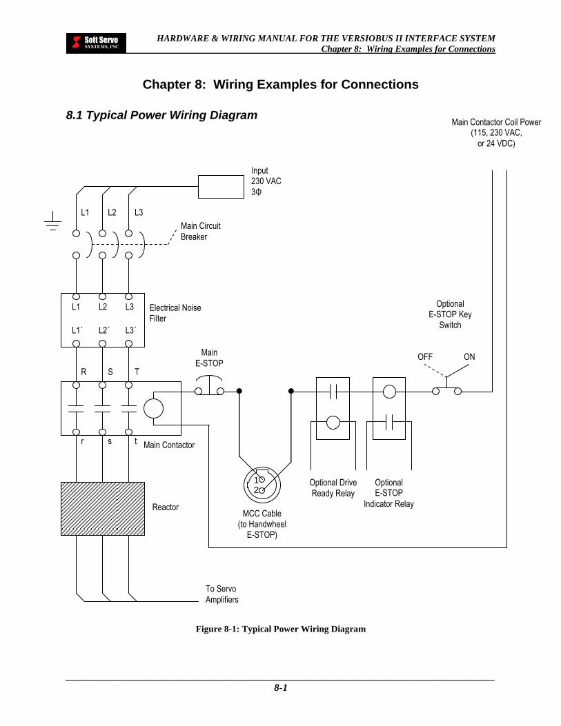
HARDWARE & WIRING MANUAL FOR THE VERSIOBUS II INTERFACE SYSTEM
Chapter 8: Wiring Examples for Connections
_____________________________________________________________________________________
8-1
Chapter 8: Wiring Examples for Connections
8.1 Typical Power Wiring Diagram
Figure 8-1: Typical Power Wiring Diagram
Input 230 VAC
3Φ
Main Circuit
Breaker
To Servo
Amplifiers
Main
E-STOP
Optional Drive
Ready Relay
Optional E-STOP
Indicator Relay
Main Contactor Coil Power (115, 230 VAC,
or 24 VDC)
Optional E-STOP Key
Switch
OFF ON
L2 L1 L3
S R T
s r t
L2 L1 L3
L2΄ L1΄ L3΄
Electrical Noise
Filter
Main Contactor
MCC Cable (to Handwheel
E-STOP)
2 1
Reactor

HARDWARE & WIRING MANUAL FOR THE VERSIOBUS II INTERFACE SYSTEM
Chapter 8: Wiring Examples for Connections
_____________________________________________________________________________________
8-2
8.2 Wiring Example of an Analog Signal
Figure 8-2: Wiring Example of an Analog Output Signal
DC-155 Servo Amp
Analog Out
AGnd
Analog In
AGnd
P
Cable Shield
Connector Shell
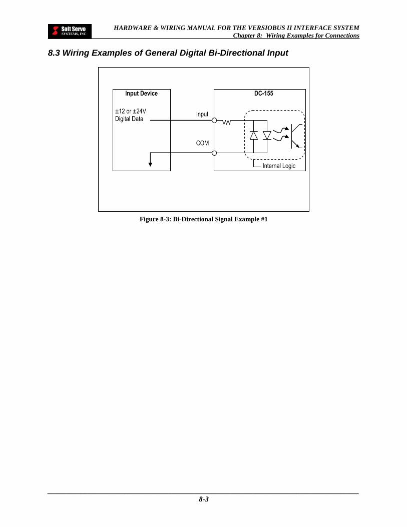
HARDWARE & WIRING MANUAL FOR THE VERSIOBUS II INTERFACE SYSTEM
Chapter 8: Wiring Examples for Connections
_____________________________________________________________________________________
8-3
8.3 Wiring Examples of General Digital Bi-Directional Input
Figure 8-3: Bi-Directional Signal Example #1
Input Device DC-155
±12 or ±24V Digital Data
Internal Logic
Input
COM

HARDWARE & WIRING MANUAL FOR THE VERSIOBUS II INTERFACE SYSTEM
Chapter 8: Wiring Examples for Connections
_____________________________________________________________________________________
8-4
8.4 Wiring Examples of Servo-Related Digital Output
Figure 8-4: Wiring Example of a Servo-Related Output in Which the Servo Drive Uses Power Provided by
the DC-155 to Operate the Opto-Isolator
Figure 8-5: Wiring Example of a Servo-Related Output in Which the Servo Drive Uses Internal Power to
Operate the Opto-Isolator
Key to Symbols
Isolated ground
Local digital
ground
DC-155
Output
Received Data
Servo Drive
+24V VCC
FPGA
GND
VCC
DC-155
Output
Received Data
Servo Drive
+24V VCC
FPGA
GND

HARDWARE & WIRING MANUAL FOR THE VERSIOBUS II INTERFACE SYSTEM
Chapter 8: Wiring Examples for Connections
_____________________________________________________________________________________
8-5
Figure 8-6: Wiring Example of a Servo-Related Output in Which the Servo Drive Does Not Use an Opto-
Isolator
Figure 8-7: Wiring Example of a Servo-Related Output in Which the Servo Drive Employs DC-155 Output to
Drive Low Current Load Using +24V Provided
DC-155
Output Received Data
Servo Drive
+24V VCC
FPGA
GND
VCC
DC-155
Output
Servo Drive
+24V VCC
FPGA
GND
Reed Relay or
Solid State Relay
Low Current
Load
Key to Symbols
Isolated ground
Local digital
ground
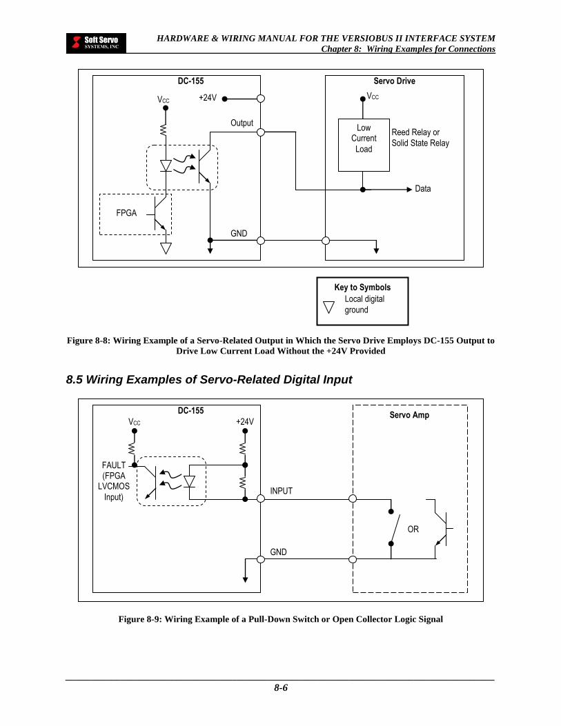
HARDWARE & WIRING MANUAL FOR THE VERSIOBUS II INTERFACE SYSTEM
Chapter 8: Wiring Examples for Connections
_____________________________________________________________________________________
8-6
Figure 8-8: Wiring Example of a Servo-Related Output in Which the Servo Drive Employs DC-155 Output to
Drive Low Current Load Without the +24V Provided
8.5 Wiring Examples of Servo-Related Digital Input
Figure 8-9: Wiring Example of a Pull-Down Switch or Open Collector Logic Signal
Key to Symbols
Local digital
ground
DC-155
Output
Data
Servo Drive
+24V VCC
FPGA
GND
Reed Relay or
Solid State Relay
Low Current
Load
VCC
DC-155
FAULT (FPGA
LVCMOS
Input)
Servo Amp +24V
OR
INPUT
GND
VCC

HARDWARE & WIRING MANUAL FOR THE VERSIOBUS II INTERFACE SYSTEM
Chapter 8: Wiring Examples for Connections
_____________________________________________________________________________________
8-7
8.6 Wiring Examples of General Input
Figure 8-10: Wiring Example of Normally Closed Limit Switches (Common Ground Connection) Connected
to DC-155 General Input
Figure 8-11: Wiring Example of Normally Closed Limit Switches (Common “+” Supply Connection)
Connected to DC-155 General Input
DC-155
NEG
POS
TB36A/B
TB-37AD
NEG LIMIT
POS LIMIT
+24V or
+12V
GIX
GIY
COM
Legend
GI = General Input
DC-155
NEG
POS
TB36A/B
TB-37AD
NEG LIMIT
POS LIMIT
+24V or +12V
GIX
GIY
COM
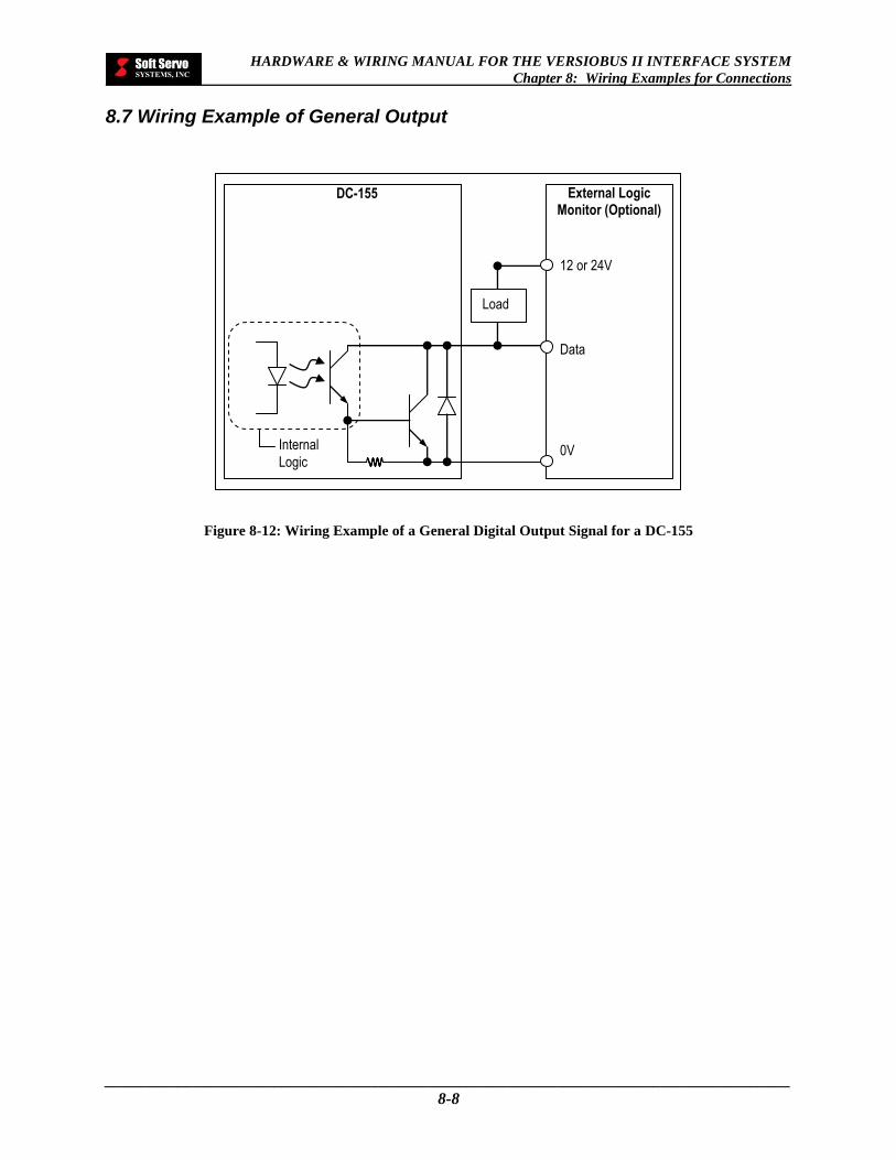
HARDWARE & WIRING MANUAL FOR THE VERSIOBUS II INTERFACE SYSTEM
Chapter 8: Wiring Examples for Connections
_____________________________________________________________________________________
8-8
8.7 Wiring Example of General Output
Figure 8-12: Wiring Example of a General Digital Output Signal for a DC-155
DC-155
Internal
Logic
12 or 24V Data 0V
External Logic Monitor (Optional)
Load

HARDWARE & WIRING MANUAL FOR THE VERSIOBUS II INTERFACE SYSTEM
Chapter 8: Wiring Examples for Connections
_____________________________________________________________________________________
8-9
8.8 Wiring Example of a Ground Connection
Figure 8-13: Wiring Example of a Ground Connection for a DC-155
Connector Shell
DC-155
24 VDC BAT
+ – G + –
Ser
vo D
rive
1
AC
S
ervo
Dri
ve 2
AC
S
ervo
Dri
ve 3
AC
Ser
vo D
rive
4
AC
I/O Devices INPUT
P
OUTPUT
AC
MO
TO
R 1
MO
TO
R 2
MO
TO
R 3
MO
TO
R 4
Key to Symbols
CHASSIS
P
Line Noise Filter
AC