Embed Size (px)
Citation preview
5 14 IEEE TRANSACTIONS ON COMPUTERS, VOL. 39, NO. 4, APRIL 1990
Hardware-Assisted Software Clock Synchronization for Homogeneous Distributed Systems P. RAMANATHAN, DILIP D. KANDLUR, AND KANG G. SHIN, SENIOR MEMBER, IEEE
Abstmct- Clock synchronization in the presence of faults has been studied extensively in recent years and several software and hardware solutions have been proposed. Software solutions re- quire nodes to exchange and adjust their individual clock values periodically. Since the clock values are exchanged via message passing, the time overhead induced by the software solutions can be substantial, especially if a tight synchronization is de- sired. Hardware solutions, on the other hand, use additional hardware to achieve a very tight synchronization with minimal time overhead. However, the prohibitive cost of the additional hardware limits their usefulness to small systems.
In this paper, we propose a synchronization scheme that strikes a balance between the hardware requirement and the clock skews attainable. The proposed scheme is a software al- gorithm that uses minimal additional hardware to achieve rea- sonably tight synchronization. Unlike other software solutions, the guaranteed worst case skews can be made insensitive to the maximum variation of message transit delay in the system. The scheme is particularly suitable for large partially-connected dis- tributed systems with topologies that support simple point-to- point broadcast algorithms. Examples of such topologies include the hypercube and the mesh interconnection structures.
Index Terms- Clock skew, distributed systems, hexagonal mesh, hypercube, synchronization.
I. INTRODUCTION
GLOBAL time base has been widely recognized as an A mportant requirement in distributed computing systems. It can be used to simplify the solutions to several design prob- lems such as checkpointing, interprocess communication, re- source allocation, and transaction processing, especially in the presence of faults [ 111. It can also be used to implement features such as deadlines and timeout that are essential for correct operation of distributed real-time systems.
A global time base can be established by synchronizing all the local clocks in the distributed system. This synchro- nization would not have been much of a problem had all the clocks including the faulty ones behaved consistently with one
Manuscript received July 1, 1989; revised November 20, 1989. This work was supported in part by NASA Grant NAG-1.296 and ONR Contract N00014-85-K-0122. Any opinions, findings, and conclusions or recommen- dations expressed in this paper are those of the authors and do not necessarily reflect the views of the funding agencies.
P. Ramanathan is with the Department of Electrical and Computer Engi- neering, University of Wisconsin, Madison, WI 53706.
D. D. Kandlur and K. G . Shin are with the Real-Time Computing Lab- oratory, Department of Electrical Engineering and Computer Science, The University of Michigan, Ann Arbor, MI 48109.
IEEE Log Number 8933893.
another. However, when some of the faulty clocks can'behave in any arbitrary manner, clock synchronization can pose some serious problems. For instance, a faulty clock can make it dif- ficult for the other clocks to synchronize themselves by either omitting or sending conflicting clock information during the course of synchronization. This kind of arbitrary behavior is referred to as a Byzantine fault, and Lamport and Melliar- Smith were the first to develop a solution to the problem of synchronizing clocks in the presence of Byzantine faults [12], 1131. Since then, the clock synchronization problem has been studied extensively, and several software and hardware solu- tions have been proposed.
The software solutions are flexible and economical but re- quire additional messages to be exchanged solely for synchro- nization [7], [13], [15], 1201. Due to their dependence on message exchanges, the worst case skews guaranteed by most of these algorithms are greater than the maximum variation in message transit delay in the system. The hardware solutions, on the other hand, can achieve a very tight synchronization with minimal time overhead, but require special additional hardware at each node of the distributed system [9], [lo], 1191, [22]. The cost of additional hardware precludes their use in large distributed systems, unless a very tight synchro- nization is essential. The hardware solutions also require a separate network of clocks that is usually different from the interconnection network between the nodes of the distributed system [19].
In this paper, we propose a synchronization scheme that strikes a balance between the hardware requirement and the clock skews attainable. Specifically, we shall develop a soft- ware solution which requires some hardware support at each node of the distributed system. The additional hardware re- quired at each node is minimal as compared to pure hardware solutions and our solution does not require a separate network of clocks. However, due to the hardware support, the worst case skews in our solution are insensitive to the maximum time required for a broadcast and are about two or three or- ders of magnitude tighter than most software solutions (see Section IV). Furthermore, the distribution of clock values by different nodes is spread over the entire resynchronization in- terval. This should be contrasted to the approach used by other software solutions where all the nodes broadcast their clock values during a specific window at the end of the resynchro- nization interval. Staggering the distribution of clock values over the entire resynchronization interval is a highly desirable feature because there is no abrupt degradation in the message
0018-9340/90/0400-0514$01 .OO O 1990 IEEE

RAMANATHAN el al.: SOFTWARE CLOCK SYNCHRONIZATION FOR DISTRIBU
deliver times caused by the almost simultaneous broadcast of clock values by all the nodes in the system.
A hardware-assisted software scheme has been proposed earlier by Kopetz and Ochsenreiter [24]. However, their scheme was mainly intended for a system in which the nodes are interconnected through a broadcast bus. In contrast, the scheme proposed here is intended for a distributed system with point-to-point interconnection topology. The problem here is more complicated because the clock messages have to be re- layed through several intermediate before reaching their desti- nation. There are also some schemes in which the worst case skews do not depend on the maximum variation in the mes- sage transit delay during a broadcast [2], [6]. In [6], clocks are intended for simulating the concept of rounds for distributed agreement algorithms rather than to keep track of elapsed time intervals. Hence, the definition of their clock is different from the definition in most other schemes [7], [9], [lo], [131, [151, [20], [22]. The scheme in [2] assumes that given a delay bound one can accurately estimate the probability of the message transit delay being greater than that bound. The main idea is to let the clock process at each node make several attempts to read the clock at another node. At the end of each attempt, the clock process can evaluate the maximum error that might occur if the clock value obtained in that attempt were used to estimate the skew. By retrying a sufficient number of times,' a clock process can read the clock at another node to any given precision with probability as close to one as desired. This scheme is particularly suitable for systems that have a master-slave arrangement in which one clock has been des- ignated or elected as a master and the other clocks act as slaves. However, this scheme is not suitable for synchroniz- ing large distributed systems because the algorithms to detect a failure of the master and to elect a new one are complex and time-consuming, especially in the presence of Byzantine faults. There is also a nonzero probability of not being able to synchronize the nonfaulty clocks, due to the probabilistic nature of the clock reading mechanism.
For the reasons outlined above, we want deterministic algo- rithms for synchronization which maintain clocks that can be used to measure real time intervals. The scheme proposed in this paper is similar to the interactive convergence algo- rithm (CNV) in [13]. The differences arise mainly because CNV is intended for a fully-connected topology, as opposed to a partially-connected topology like the hypercube [17] or the mesh [l]. Although CNV could be used in a partially- connected system, it is not well suited for such a system due to the fact that the worst case skews in CNV are greater than the difference between the maximum and the minimum mes- sage transit delay in the system. In contrast, as illustrated in Section IV, the worst case skews in the proposed scheme are orders of magnitude smaller than the maximum time required for a reliable broadcast. In addition, the worst case skews do not depend on this maximum time beyond a certain limit.
This paper is organized as follows. In Section 11, the clock synchronization problem is formally stated. The proposed software synchronization algorithm and the proof of its cor-
TED SYSTEMS 515
rectness are presented in Section 111. Several numerical ex- amples are given in Section IV. The paper concludes with Section V.
11. PROBLEM STATEMENT Before formally stating the clock synchronization problem,
it is necessary to introduce the notation and the terminology to be used here, which are similar to the ones in [13]. (They are repeated here for completeness.)
Definition 1: The time that is directly observable in some particular clock is called its clock time. This should be con- trasted to the term real time, which is measured in an assumed Newtonian time frame that is not directly observable.
Definition 2: Let c be a mapping from clock time to real time, where c(T) = t means that at clock time T the real time is t. Then, two clocks C I and c2 are said to be 6-synchronized at a clock time T if and only if IC 1 ( T ) - c ~ ( T ) 1 5 6 .
We adopt the convention of using lowercase letters to de- note quantities that represent real time and uppercase letters to denote quantities that represent clock time. It is convenient to pretend that clocks run continuously, so a clock is a continu- ous function on some interval. Also, the nonfaulty clocks are assumed to be monotonic. An implementation that achieves this monotonicity is discussed later in this paper.
Definition 3: A clock c is a good clock during the real time interval [t 1 , t2] if it is a monotonic, differentiable func- tion on [TI, T2] where c(Ti) = ti, i = 1, 2, and for all T in [TI 9 T21 l%g-ll<!? 2
for some constant p that represents the drift rate of the good clocks.
The problem of clock synchronization can now be formally stated as follows. Consider a distributed system with N nodes in which a maximum of m of these nodes are faulty. Each node executes a clock process (CP) to maintain a time base for all the activities on that node. Let cp denote the clock at node p . For simplicity, suppose the clocks are resynchronized every R seconds. Let T(') = TcO) +iR and R") be the interval [T('), T('+')]. Due to the correction made at the end of ev- ery resynchronization interval, the clock at each node can be viewed as a sequence of logical clocks, one for each resyn- chronization interval. Let c$' denote the logical clock at node p in the ith resynchronization. Then, c$)(T) = cbo'(T + @), where .$) is the aggregate correction applied to the clock since the start of the system. For notational convenience, let
C P . Definition 4: A node p is said to be nonfaulty up to
time T('+') if it is nonfaulty during the real time interval [ c $ ) ( ~ ( ~ ) ) , ,(i) P ( ~ ( i + l ) ) ] .
Using the above notation, the two clock synchronization conditions can be stated as
Sl) If nodes p and q are nonfaulty up to time T('+'), then W E R(')
@) = 0 and c r ' =
IC$)(T) - c t ) ( ~ ) I < 6 for some constant6.
S2) If node p is nonfaulty up to time T('+'), then
' This will, however, induce additional time overhead. I$+') - l$)l < c for some constant E.
516 IEEE TRANSACTIONS ON COMPUTERS, VOL. 39, NO. 4, APRIL 1990
Intuitively, the first condition states that the difference in clock times on two nonfaulty nodes is always bounded. The second condition states that there is a bound on the amount by which a clock can change its value during one resynchronization in- terval.
111. PROPOSED SOLUTION Since the synchronization scheme proposed in this paper
is based on Algorithm CNV, we will first briefly describe the algorithm as proposed in [13] . We will then identify the problems of adapting the algorithm to a distributed system that is not fully connected, and present a solution that eliminates those problems.
Algorithm CNV assumes that the clocks are initially syn- chronized and that they drift apart only by a bounded amount during a resynchronization interval. In every resynchroniza- tion interval, each CP reads the value of the clock at all other nodes. If the value of a clock read differs from the clock at its node by an amount greater than a threshold, CP replaces that value by its own clock value. CP then computes the average of all such values and sets the local clock to that average. In [ 1 3 ] , it is shown that this algorithm can achieve synchroniza- tion, and requires a minimum of 3 m + 1 nodes to tolerate m faults.
Three major problems arise when this algorithm is used in a distributed system that is not fully connected. First, the clock message received at a node may be corrupted by a faulty intermediate node through which it was relayed. Second, due to the queueing delay for clock messages, there may be a substantial difference between the real time at which a CP sends the clock value and the real time at which another CP receives that message. Therefore, subtracting the clock value in the received message from the current clock value will not reflect the actual skew that exists between the clocks of the two nodes. This problem, which is present even if the system is fully connected, is aggravated when system is partially- connected because the clock message has to be relayed through intermediate nodes. Third, there may be a delay between the receipt of a clock message from the network and the time at which it is processed. A similar delay is possible between the time at which a CP sends the message and the time at which the message is placed on the network. The first problem is eliminated in the proposed solution by using a broadcast algo- rithm that delivers multiple copies of the message to all CP’s through node-disjoint paths. The second problem is reduced by requiring the CP at each intermediate node to append to the message the delay (according to the local clock) incurred at that node. The third problem is handled by recording the time at which a clock message is sent or received.
A CP broadcasts the local clock value to all other CPs’ at a specified time in the resynchronization interval according to its clock. The broadcast algorithm is such that all CP’s receive multiple copies of the clock message through node-disjoint paths. The number of copies used in the broadcast algorithm depends on the maximum number of faults to be tolerated and the fault model for the system. When a CP receives a clock message sent by some other CP, it records the time (according to its local clock) at which the message was received. Then, in
accordance with the broadcast algorithm, it relays the message to other CP’s. Before relaying the message, it appends to the message the time elapsed (according to its own clock) since the receipt of the message. At the end of a resynchronization interval, it computes the skews between the local clock and the clock of the source node for each one of the copies it has received. It then selects the ( m + 1)th largest value as an estimate of the skew between the two clocks. It is shown in Section 111-D that this selected value is a good estimator of the clock skew between the two nodes. The average of the estimated skews over all nodes is used as the correction to the local clock. As in CNV, the proposed scheme requires a minimum of 3 m + 1 nodes to tolerate m Byzantine faults.
The above steps are explained in Section 111-C in terms of four concurrent tasks: CLOCK-SEND, CLOCK-RELAY, CLOCK-RECEIVE, and CLOCK-CORRECTION . An effi- cient implementation of these tasks requires some hardware support and a reliable broadcast mechanism.
A . Hardware Support A clock message contains the following information: the
node at which the broadcast was initiated (namely, the ini- tiator), the node from which the message was most re- cently relayed (namely, the immediate sender), and five words W 1, W2, . . . , W5 shown below. The relative ordering of these words in the message depends on the format being used in the system.
W I : Clock time of the initiator when this message was transmitted.
W, : Clock time of the immediate sender when it received this message.
W3: Clock time of the immediate sender when it relayed this message.
W4: Accumulated transit delay not counting the delay at the immediate sender.
W5: The time on the local clock when this message was received.
The hardware circuitry at each node helps in updating these words. When a clock message is received it updates W, with the local time. An interrupt is then generated to the processor that runs the clock tasks at that node. After the clock tasks have completed their processing, the message is scheduled for forwarding. While the message is being transmitted, the hardware circuitry inserts the local clock time in place of W3. The other operations performed on these words are explained in the formal description of the clock tasks later in this section.
A special circuit is required to maintain a continuous mono- tone logical clock at each node. A possible solution is as follows. A high-frequency clock generated by a crystal os- cillator is divided by a programmable counter and the divided clock is used to increment a counter that contains the logical clock. The factor used to divided the high-frequency clock de- pends on the correction that needs to be applied to the logical clock. If at the end of a resynchronization interval, the correc- tion is positive (negative), then the factor used to divide the high-frequency clock is increased (decreased) from its nom- inal value. For example, a 32 MHz clock can nominally be divided by 32 to get a logical clock whose resolution is 1 ps.
RAMANATHAN et at. : SOFTWARE CLOCK SYNCHRONIZATION FOR DISTRIBUTED SYSTEMS
This factor can be changed either to 36 or 28 depending on whether the correction is positive or negative, respectively.
B. Reliable Broadcast
A reliable broadcast mechanism is especially important in a partially-connected distributed system because a process may have to deliver its clock value to the other processes via sev- eral intermediate nodes. However, since the nonfaulty CP’s need not agree on the clock value at a faulty node, it is not necessary to use an interactive consistency algorithm [ 5 ] , [14] to correctly deliver the clock values.
In the presence of m Byzantine faults, the following scheme can be used to reliably deliver the clock values. For each pair of nodes, determine a set of 2m + 1 node-disjoint paths. The CP at a nonfaulty node then individually sends 2m + 1 copies of the local clock value to the CP at each node through the pre- determined paths for that node. As shown in [23] this scheme does not require authentication. It requires: 1) the network to be 2m + 1 connected, and 2) a process should be able to iden- tify the node from which a received message originated and the node from which it was most recently relayed. These two requirements are necessary for any algorithm that is resilient to m Byzantine faults when authentication is not available [4]. It is shown in Theorem 1 that a CP can reliably estimate the skew between the local clock and the clock at another node from the multiple copies of the clock message it receives from the CP at that node.
The above scheme, albeit very general, requires each CP to send a large number of messages, thus resulting in substantial time overhead. However, for interconnection topologies, like the hypercube [17] and the C-wrapped hexagonal mesh [ l ] , there are reliable broadcast algorithms available [8], [16] to reduce this overhead. As in the scheme described above, they deliver 2m + 1 copies of the clock message through node- disjoint paths to every node in the system. But they make use of the properties of the topology to reduce the number of messages that have to be sent by a process. In fact, one can show that the number of messages sent by a process is the minimum required to guarantee a reliable delivery with- out using digital signatures. Due to the importance of a reli- able broadcast mechanism for distributed algorithms that are resilient to Byzantine faults, one can argue that most fault- tolerant distributed systems will use topologies that support simple broadcast algorithms similar to the ones in [8] and [16]. Consequently, such a broadcast mechanism will be as- sumed to exist in the distributed systems being synchronized.
C . Detailed Description A CP is comprised of four concurrent tasks. The operations
of these four tasks required can be described in terms of the following basic functions. local-time( ) Returns the current time on the local
clock. btime@) Returns the time at which p is supposed
to broadcast its clock message in the current resynchronization interval. Initiates broadcast of k copies of a clock message with time set at t .
initiate-bcast(k, t )
1. loop 2. 3. 4. endif; 5 . endloop;
if (local-time( ) = btirne(p)) initiate-bcast(2m + 1, local_tirne( ));
Fig. 1. CLOCK-SEND task at node p
wl(M), . . . ,w5(M)
receive( )
initiator(A4)
select(skews, 1)
The five clock words in the message M . Blocks until a clock message arrives and returns the received message. Returns the node at which the broadcast of message M was initiated. skews is an array of estimated skews with respect to a particular node com- puted from copies of clock messages received from the CP at that node. The function select( ) orders these skews and returns the Ith value.
CLOCK-SEND: The CLOCK-SEND task is responsible for initiating a reliable broadcast in each resynchronization interval, as shown in Fig. 1. The time at which the broadcast takes place depends on the node and is staggered throughout the resynchronization interval. This alleviates the problem of transient loading which would otherwise occur due to the al- most simultaneous broadcast of clock messages. The reliable broadcast delivers 2m + 1 copies of the message to each CP through node-disjoint paths if all CP’s adhere to the broadcast algorithm. However, if some nodes are faulty and do not ad- here to the broadcast algorithm, then fewer than 2m + 1 copies may be delivered. Given that there are at most m faulty nodes in the system, each CP will receive at least m + 1 copies re- layed through nonfaulty nodes. It is shown in Theorem 1 that the CP’s at all nonfaulty nodes can reliably estimate the clock skew from the copies received.
Due to contention for network resources there may be a time delay between the initiation of a broadcast (i.e., line 3 of Fig. 1) and the time at which the copies are transmitted on the network. To account for this delay, the time on the local clock is inserted in W I and W2 while the broadcast is being initiated. Also, the cumulative transit delay W4 is initialized to 0. During transmission, the hardware circuitry at that node will insert the current time in place of W3. The delay between the initiation of the broadcast and the time at which the copy was transmitted, indicated by (W3 - W2), will be accumulated in W4 by the CLOCK-RELAY task of the node that is receiving this message.
CLOCK-RELAY: The CLOCK-RELAY task (Fig. 2) gets activated when a clock message broadcast by some other CP is received. It is responsible for relaying the message to other CP’s as per the broadcast algorithm. It is also responsi- ble for updating the words W1, . . . , W5 in the clock message.
The CLOCK-RELAY task checks whether the initiator specified in the message is supposed to be broadcasting its clock value at this time instant. This check is used to suppress spurious messages generated from faulty nodes. This is pos- sible if there is a bound on the time to complete a broadcast, say U. If the message is authentic, (W3 - W2) is added to W4 to accumulate the transit delay incurred by the message at
518 IEEE TRANSACTIONS ON COMPUTERS, VOL. 39, NO. 4, APRIL 1990
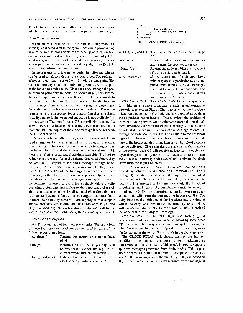
1. constant MAXEROADCASTSIME = U ;
3. M := receive( ); 4. source := initiator(M); 5. 6 .
8. 9. endif; 10. endloop;
2. loop
if ( Ilocal-time( ) - btime(source)l 5 MAXBROADCAST-TIME ) w4(M) := w4(M) + w3(M) - wZ(M);
relay the message according to the broadcast algorithm; 7. w2(M) := w5(M);
Fig. 2. CLOCK-RELAY task.
1. constant MAXBROADCAST-TIME = U ; 2. loop 3. M := receive( ); 4. source := initiator(A4); 5. 6. copy := Curreut.copy[source]; 7. 8. 9. endif; 10. endloop;
if ( IIocal-time( ) - btime(source)l 5 MAXBROADCAST-TIME )
Delta[source][copy] := w5(M) - (w4(M) t w3(M) - wZ(M)) - wl(M); Current-copy(source] := Current-copy[source] + 1;
Fig, 3. CLOCK-RECEIVE task.
1. constant THRESHOLD = A; 2. loop 3. 4. totalskew := 0 5. 6. 7. if (Skewlq] > THRESHOLD) 8. Skew[q] = 0; 9. endif; 10. 11. endfor; 12. 13. endif; 14. 15. endloop;
if (localfime( ) = resynctime( ))
for q = 1 to NUMBER-OF-PROCESSES SkewIq] := select(Delta[q), m + 1);
totalskew := totalskew + Skew[q];
correction := totalskew f NUMBER-OF-PROCESSES;
initialize Currentxopy, etc. for the next resynchronization interval;
Fig. 4. CLOCK-CORRECTION task.
the immediate sender. This node now becomes the immediate sender for the next step.
CLOCK-RECEIVE: When a message is received, the CLOCK-RECEIVE task (Fig. 3) first verifies the authentic- ity of the message. It then computes the skew between the local clock and the clock at the node where the broadcast was initiated and adjusts the skew by subtracting the accu- mulated delay. This operation is performed for each copy that is received and the resulting skews are passed on to the CLOCK-CORRECTION task.
CLOCK-CORRECTION: The CLOCK-CORRECTION task (Fig. 4) corrects the local clock based on the skews cal- culated by CLOCK-RECEIVE. It first selects the estimated skew for a particular node from the values computed for the copies received from that node. If the estimated skew is greater than a threshold, A , it is replaced by zero. The choice of A follows from the proof of correctness (see Lemma 5). The correction applied to the local clock is the average of the estimated skews over all nodes.
D. Proof of Correctness In this section, we show that the proposed solution can
ensure synchronization if the following assumptions hold in the system.
Al) For all nodes p and q, Ic,(T(O)) - c,(T(”)) < 60, where 60 is a constant.
A2) If node p is nonfaulty during the time interval [t 1 , iz], then c p is a good clock during the interval, i.e.,
A3) In a reliable broadcast initiated from a nonfaulty node, all copies relayed through nonfaulty nodes are delivered within a time bound U.
A4) Suppose S1 and S2 hold for i and node p is nonfaulty up to time T(’+’). Also suppose that the CP at a nonfaulty node q sends a message containing q’s clock value to p at some time TO in R(’) according to q ’ s clock. This message reaches p through a relay (possibly empty) of nodes. The CP at each relay node alters the words W1, . . . , W5 in the message as described in CLOCK-RELAY. From the message received, the CP at p computes a value Aqp as described in CLOCK-RECEIVE. If all the relay nodes are nonfaulty, then
Ic$’(To + A q p + Q ) - Q - c;’(To)) < 6
where Q = W5 - (W4 + W3 - W2) is an estimate of the total transit delay incurred by the message and E is a constant.
A5) The upper bound U on the time required to complete a reliable broadcast is such that U 5 R f N , where R is the resynchronization interval and N is the number of nodes in the system.
Intuitively, A1 states that clocks are initially 60- synchronized to each other. A scheme to achieve this initial synchronization is described later. A2 states that if a node is nonfaulty, then so is its clock. In other words, no dis- tinction is made between a faulty clock and a faulty node. A3 states that there is an upper bound U on the time to complete a reliable broadcast. In A4, cz’(T0 + A,, + Q) is the real time at which the message is received at p and c:’(To) is the real time at which the message was sent from q. Since Q is the total delay incurred by the message in tran-
the skew at p based on this message. Therefore, A4 states that if all CP’s adhere to the scheme for broadcasting and relay- ing the clock messages, then the error in estimating the skew is bounded. This assumption is reasonable because the errors occur, in most part, due to: 1) the transit delay incurred at an intermediate node is measured using a discrete logical clock as opposed to a continuous clock, and 2) the logical clock at an intermediate node drifts from real time while measur- ing the delay incurred at a node. The existence of a bound then follows from the observation that the time required for a broadcast is bounded, the drift rates of nonfaulty clocks are bounded, and the nonfaulty clocks have a known finite resolution.
A5 states that a broadcast initiated by a CP will always complete before the next CP initiates its broadcast. As a result, in the proposed scheme, at most one CP will be broadcasting its clock value at any given time. It is shown later in this paper that for typical values of all relevant parameters in the system, A5 is not a very restrictive assumption.
Given these assumptions, it can be proved that the nonfaulty clocks will remain synchronized throughout the operation of the system. Due to the inherent complexity of the notation, an informal explanation of the lemmas is first presented. The lemmas are similar to the ones in [13]. The differences arise mainly because the worst case skews in the proposed scheme are shown to be less than the maximum transit delay during a broadcast and because of the modeling assumption that a CP may have to use a few relay nodes to convey its clock value
sit, cp (‘1 (To+A,, +Q) -Q -c:’(To) is the error in estimating
RAMANATHAN et at. : SOFTWARE CLOCK SYNCHRONIZATION FOR DISTRIBUTED SYSTEMS
~
519
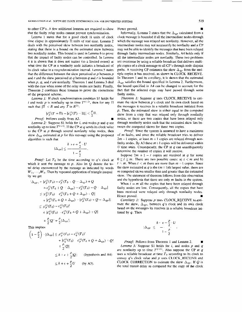
to other CP’s. A few additional lemmas are required to show that the faulty relay nodes cannot prevent synchronization.
Lemma 1 states that for a good clock II units of clock time elapse in approximately H units of real time. Lemma 2 deals with the perceived skew between two nonfaulty nodes, stating that there is a bound on the estimated skew between two nonfaulty nodes. This bound is used in Lemma 6 to prove that the impact of faulty nodes can be controlled. In Lemma 4 it is shown that it does not matter (to a limited extent) at what time the CP at a nonfaulty node initiates a broadcast of its clock value in a resynchronization interval. Lemma 5 states that the difference between the skew perceived at p between p and r and the skew perceived at q between q and r is bounded when p , q, and r are nonfaulty. Theorem 1 and Lemma 3 deal with the case when some of the relay nodes are faulty. Finally, Theorem 2 combines these lemmas to prove the correctness of the proposed scheme.
Lemma 1: If clock synchronization condition S1 holds for i and node p is nonfaulty up to time T(’+2) , then for any II such that < R and any T in R(’) :
(c$’(T + rI) - [c$’(T) + rI]l < en. 2 Proof: Follows easily from A2. W
Lemma 2: Suppose S1 holds for i, and nodes p and q are nonfaulty up to time T(’+’). If the CP at q sends its clock value to the CP at p through several nonfaulty relay nodes, then skew Aqp estimated at p for this message using the proposed algorithm is such that
P 2 P
& + € + - . U l 4 P l 5
1 L 2
Proof: Let To be the time according to q ’ s clock at which it sent the message to p . Also let Q denote the to- tal delay encountered by the message as indicated by words “1, . . . , W5. Then by repeated application of triangle inequal- ity we get
JAqp 1 = Ic;’(To) - c;’(To + Q + n q p ) + Q + c$’(To + Q + A q p ) - TO) - Q - A q p I
5 Ic$’(To) - TO + Q + A q p ) + QI + (c;’(To + Q + Aqp) - [c$’(To) + Q + AqplI
<_ (c$’(To) - c$’(To>J
+ (c$’(To) - c$’(To + Q + A q p ) + QI
+ zlQl+ zIAqPI* P P
This implies
(1 - ;) ’ la,, 1 5 Ic$’(To) - c$’(To)l
+ (c!’(To) - c;’(To + Q + A 4 ~ ) + Q I + ; I Q 1
P 5 6 + E + IQ 1 (hypothesis and A4)
5 6 + e + :U (by A3). 2
Hence proved. Informally, Lemma 2 states that the Aqp calculated from a
clock message is bounded if all the intermediate nodes through which the message was relayed are nonfaulty. However, all the intermediate nodes may not necessarily be nonfaulty and a CP may not be able to identify the messages that have been relayed through faulty intermediate nodes. Similarly, A4 holds only if all the intermediate nodes are nonfaulty. These two problems are overcome by using a reliable broadcast that delivers multi- ple copies of a clock message to all CP’s through node-disjoint paths. A receiving CP estimates the skew Aqp from the mul- tiple copies it has received, as shown in CLOCK-RECEIVE. In Theorem 1 and its corollary, it is shown that the estimated Aqp satisfies the bound specified in Lemma 2. Furthermore, the bound specified in A4 can be changed to account for the fact that the selected copy may have passed through some faulty nodes.
Theorem 1: Suppose q uses CLOCK-RECEIVE to esti- mate the skew between p’s clock and its own clock based on the messages it receives in a reliable broadcast initiated from p . Then, the estimated skew is either equal to the computed skew from a copy that was relayed only through nonfaulty nodes, or there are two copies that have been relayed only through nonfaulty nodes such that the estimated skew lies be- tween the computed skews for these two copies.
Proof: Since the system is assumed to have a maximum of m faults, and since the reliable broadcast tries to deliver 2m + 1 copies, at least m + 1 copies are relayed through non- faulty nodes. By A3 these m + l copies will be delivered within U time units. Consequently, the CP at q can unambiguously determine the number of copies it will receive.
Suppose 2m + 1 - t copies are received at q for some 0 5 t 5 m. There are two possible cases: a) t < m and b) t = m. When t < m there are more than m i- 1 copies. Since the skew estimated at q is the ( m + 1)th largest value, there are m computed skews smaller than and greater than the estimated skew. The statement of theorem follows from this observation and the hypothesis that there are only m faults in the system.
When t = m all the copies that have been relayed through faulty nodes are lost. Consequently, all the copies that have been received were relayed only through nonfaulty nodes.
Corollary I : Suppose p uses CLOCK-RECEIVE-ta&sti- mate the skew, A q p , between q ’ s clock and its own clock based on the messages its receives in a reliable broadcast ini- tiated by q. Then
Hence proved.
Proofi Follows from Theorem I and Lemma 2. W Lemma 3: Suppose S1 holds for i , and nodes p and q
are nonfaulty up to time T(‘+’). Also suppose the CP at q uses a reliable broadcast at time To according to its clock to convey q’s clock value and p uses CLOCK-RECEIVE and CLOCK-CORRECTION to estimate the skew A q p . If Q is the total transit delay as computed for the copy of the clock

520 IEEE TRANSACTIONS ON COMPUTERS, VOL. 39, NO. 4, APRIL 1990
message that was used to estimate the skew, then Proof: Let TO be as in Lemma 3. Then
@'(T + II + Q + A q p ) - Q - c$)(T + n)l = (c"'(T0 + T + II + Q + A,, -To)
Proof: If the copy used to estimate the skew was re- layed only through nonfaulty nodes, then the lemma follows from A4. So the more interesting case is when it was re- layed through at least one faulty node. In this case, it follows from Theorem 1 that there are at least two copies relayed only through nonfaulty nodes, say through paths P I and P2, such that the estimated skew lies between the skews computed from these two copies. Let Q I and Q2 be the accumulated transit delays, and let AqP(P1) and Aqp(P , ) be the computed skews from the clock messages that were relayed through paths P1 and P2, respectively.
Without loss of generality, we can assume that Aqp(PI ) 5 A q p <_ Aqp(P2). Adding and subtracting a few terms to the inequality AqP(Pl ) 5 Aqp we get
Using Lemma 1, A4, Corollary 1, and a few substitutions, the above equation can be shown to be equivalent to
c$'(To) - c$'(To) - p ( 6 + v> + Aqp(P1) 2 (1 -
Lemma 5: Suppose S1 holds for i , and nodes p , q, and r are nonfaulty up to time T(jt2). Also suppose the CP at r uses a reliable broadcast to convey its clock value, and suppose p and q use CLOCK-RECEIVE and CLOCK-CORRECTION to estimate the skew between their clock and r's clock. Let &,(a) and &,,(b) be the estimated skews at p and q, re- spectively, at the end of line 9 in CLOCK-CORRECTION with threshold A = (6 + E + p / 2 . U)/(1 - p / 2 ) . Let Q(") and Q@) denote the total transit delay computed at p and q, respectively, from the copy used to estimate the skew. Then for any T in R(')
Ic$)v) + a r p ( a > - [ct)(T) + i~~,(b)]l P I 2 ( i +2pR) + ~ ( - ;) +
Pro08 It follows from Corollary 1 that when A is cho- sen as in the hypothesis, lArq(a)l 5 A and lArq(b)l 5 A . SO &,(a) = Arp(a ) and arq(b) = Arq(b), where A,,(a) and Arq(b) are the estimate of the skews at the end of line 6 of CLOCK-CORRECTION. For notational simplicity, let Arp Arp(a) and Arq e Arq(b) . Then
Ic$)v) + &,,(a> - [c$)(T) + ~ r q ( b > l ~
= (c$'(T) + Arp + Q(") - Q(") + Q(b)
Now by adding and subtracting a few terms on the left-hand + Q(b) - Q ( " ) I side and then using Lemma 1 and A4, we get
\ ' I + Q(b) - Q(') I + ~ (&+€+U)
(1 - ;) This proves one side of the required inequality. To prove the other side, we can start with Aqp 5 Aqp(P2) and show that
I (c$)(T + Arp + Q'"') - cY'(T) - Q(@I
+ Ic$)(T + Arq + Q@)) - c?'(T) - Q(b)l p ( 6 + E + U ) C$)(TO + Q + A 4 P ) - Q - c$'(To) 5 E +
Hence, the lemma follows. Lemma 4: Suppose S1 holds for i , and nodes p and q
at q uses a reliable broadcast algorithm and that the CP
- 2) are nonfaulty up to time T('+'). Also suppose that the CP
at p estimates the skew Aqp as in CLOCK-RECEIVE and CLOCK-CORRECTION. If Q is the total transit delay as
(6 + E + U) from Lemma 4. 5 2 ( i + 2pR) + ~ P
(1 - s) computed from the copy used to estimate the skew, then for any II such that Ill < R and any T i n R(') Lemma 6: Suppose S1 holds for i , and nodes p and q
are nonfaulty up to time T('+2). Also suppose that p and 4 IC$'(T + II + Q + Aqp) - Q - ct'(T + H)l 5 + 2pR. use CLOCK-RECEIVE and CLOCK-CORRECTION to es-
RAMANATHAN et at.: SOFTWARE CLOCK SYNCHRONIZATION FOR DISTRIBUTED SYSTEMS 52 1
timate the skew between their clock and the clock at node r. Let &,,(a) and L,,(b) be the estimated skews at p and q, respectively, at the end of line 9 in CLOCK-CORRECTION. Then for any T in R(‘)
Ic$)(T) + &,(a) - [ct’(T) + Arq(b)]l 5 6 + 2A. Proof: By the hypothesis that S1 holds for i, we have
Ic$)(T) - c!)(T)I < 6.
Since h,, and Er, are by definition no larger than A , the result follows.
Theorem 2: If A1-A5 hold and if a) 3m < N and the interconnection network is 2m + 1 con-
nected
then the algorithm presented in the previous section satisfies Conditions S1 and S2 with C = A .
Proof: Let A, and A, be the correction com- puted at p and q, respectively, at the end of line 12 in CLOCK-CORRECTION. Condition S2 holds because the correction to the local clock is the average of N terms, each less than A . Condition S1 can be proved by induction on i. For i = 0, A1 implies that two nonfaulty clocks that are syn- chronized to within 60 at time T(O) will remain synchronized to within 60 +pR at time T(’ ) = T(O) + R. Condition S1 follows from A1 and the hypothesis.
Now suppose that S1 holds for i. We need to prove that it holds for i + 1. Assume that p and q are both nonfaulty up to time T(i+2). For clarify of presentation, we will use Er, and Erg without explicitly specifying the nodes through which the clock values were relayed from r t o p and q. Also let T denote T(’+’). Then for any T’ in R(’+’) we have
Ic$+’)(T’) - c$+l)(T’)l
5 Ic$+’)(T) - c~+’)(T)I + pR by A2
= Ic$’(T + A,) - c$’(T + A ,)I + PR from the algorithm
(c$)(T) + A, - [ct’(T) + A,]( + PR + ;(A, + A,)
from Lemma 1
r = l
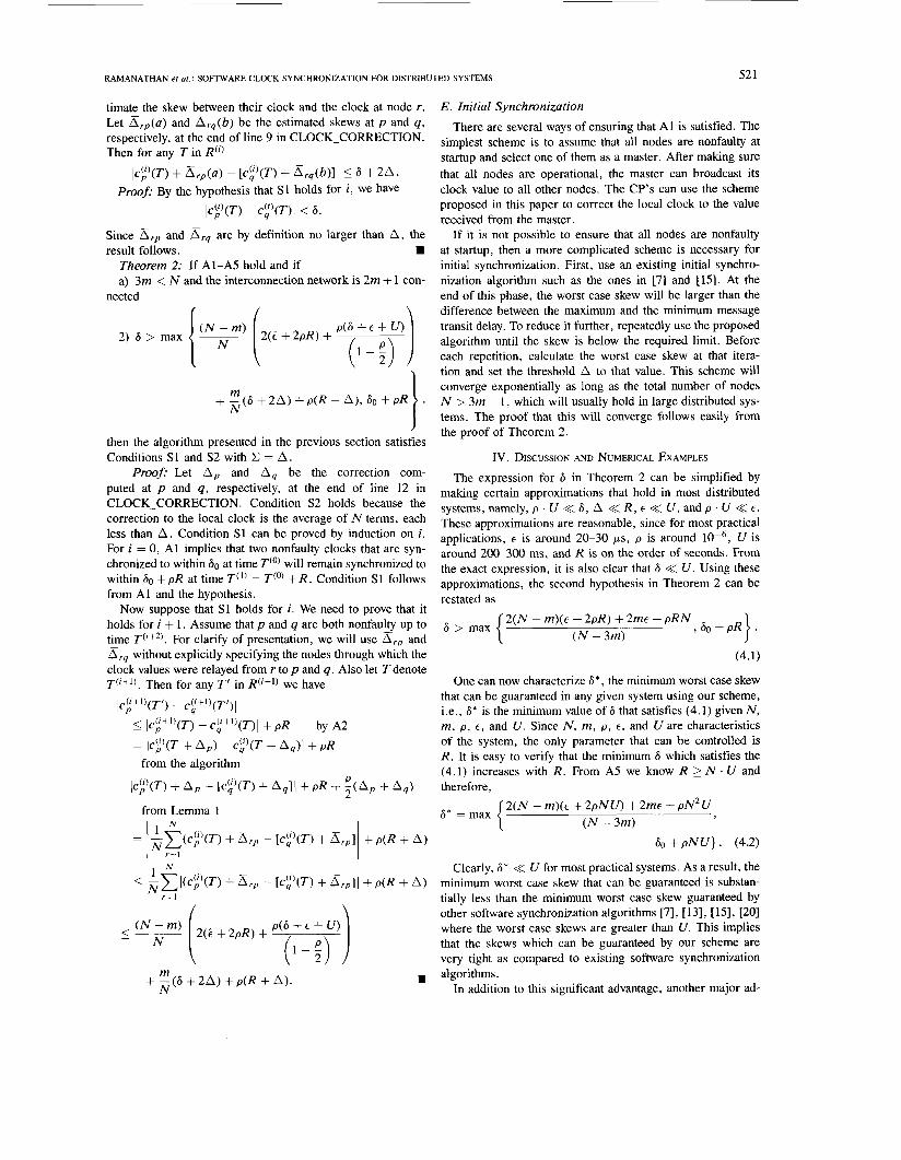
E . Initial Synchronization There are several ways of ensuring that A1 is satisfied. The
simplest scheme is to assume that all nodes are nonfaulty at startup and select one of them as a master. After making sure that all nodes are operational, the master can broadcast its clock value to all other nodes. The CP’s can use the scheme proposed in this paper to correct the local clock to the value received from the master.
If it is not possible to ensure that all nodes are nonfaulty at startup, then a more complicated scheme is necessary for initial synchronization. First, use an existing initial synchro- nization algorithm such as the ones in [7] and [15]. At the end of this phase, the worst case skew will be larger than the difference between the maximum and the minimum message transit delay. To reduce it further, repeatedly use the proposed algorithm until the skew is below the required limit. Before each repetition, calculate the worst case skew at that itera- tion and set the threshold A to that value. This scheme will converge exponentially as long as the total number of nodes N > 3m + 1, which will usually hold in large distributed sys- tems. The proof that this will converge follows easily from the proof of Theorem 2.
IV. DISCUSSION AND NUMERICAL EXAMPLES
The expression for 6 in Theorem 2 can be simplified by making certain approximations that hold in most distributed systems, namely, p . U << 6 , A << R , E << U , and p . U << E .
These approximations are reasonable, since for most practical applications, E is around 20-30 ps, p is around lop6, U is around 200-300 ms, and R is on the order of seconds. From the exact expression, it is also clear that 6 << U . Using these approximations, the second hypothesis in Theorem 2 can be restated as
2(N - m)(E + 2pR) + 2mc + pRN ( N - 3rn)
6 > max > 60 + PR}.
(4.1)
One can now characterize 6*, the minimum worst case skew that can be guaranteed in any given system using our scheme, i.e., 6* is the minimum value of 6 that satisfies (4.1) given N , m, p , E , and U. Since N , m, p , E , and U are characteristics of the system, the only parameter that can be controlled is R. It is easy to verify that the minimum 6 which satisfies the (4.1) increases with R. From A5 we know R 2 N . U and therefore,
{
2(N - m)(c + 2pNU) + 2mc + pN2U ( N - 3m)
6* =max 3
60 + pNU} . (4.2)
Clearly, 6* << U for most practical systems. As a result, the minimum worst case skew that can be guaranteed is substan- tially less than the minimum worst case skew guaranteed by other software synchronization algorithms [7], [ 131, [ 151, [20] where the worst case skews are greater than U. This implies that the skews which can be guaranteed by our scheme are very tight as compared to existing software synchronization algorithms. -
1 . In addition to this significant advantage, another major ad-
522
3 3 200-
0)
U 150-
:: 1 0 0 - &
50 -
IEEE TRANSACTIONS ON COMPUTERS, VOL. 39,
2 4 3 3 4 5
16 3
Fig. 5 . A C-wrapped hexagonal mesh of dimension 3.
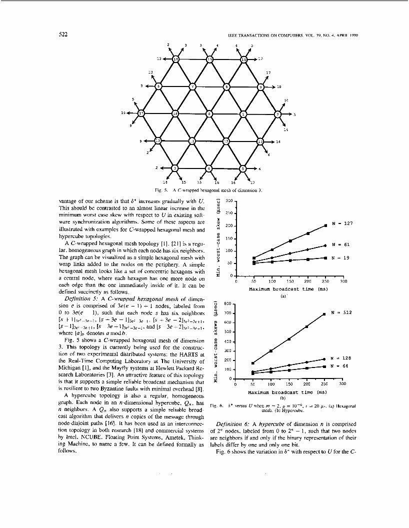
vantage of our scheme is that 6* increases gradually with U. This should be contrasted to an almost linear increase in the minimum worst case skew with respect to U in existing soft- ware synchronization algorithms. Some of these aspects are illustrated with examples for C-wrapped hexagonal mesh and hypercube topologies.
A C-wrapped hexagonal mesh topology [ 1 1 , [21] is a regu- lar, homogeneous graph in which each node has six neighbors. The graph can be visualized as a simple hexagonal mesh with wrap links added to the nodes on the periphery. A simple hexagonal mesh looks like a set of concentric hexagons with a central node, where each hexagon has one more node on each edge than the one immediately inside of it. It can be defined succinctly as follows.
Definition 5: A C-wrapped hexagonal mesh of dimen- sion e is comprised of 3e(e - 1 ) + 1 nodes, labeled from 0 to 3e(e - l ) , such that each node s has six neighbors
+ 113e2-3e+l, 1s + 3e - 113e2-3e+1> 1s + 3e - 2 1 3 e 2 - 3 e t l 9
[ ~ - 1 1 3 e 2 - 3 e + 1 9 1s -3e+113e2-3e+l? and [ ~ - 3 e +213e2-3e+1, where [a]b denotes a mod b .
Fig. 5 shows a C-wrapped hexagonal mesh of dimension 3 . This topology is currently being used for the construc- tion of two experimental distributed systems: the HARTS at the Real-Time Computing Laboratory at The University of Michigan [ 11, and the Mayfly systems at Hewlett Packard Re- search Laboratories [ 3 ] . An attractive feature of this topology is that it supports a simple reliable broadcast mechanism that is resilient to two Byzantine faults with minimal overhead [8] .
A hypercube topology is also a regular, homogeneous graph. Each node in an n-dimensional hypercube, Q,,, has n neighbors. A Q n also supports a simple reliable broad- cast algorithm that delivers n copies of the message through node-disjoint paths [16]. It has been used as an interconnec- tion topology in both research [18] and commercial systems by Intel, NCUBE, Floating Point Systems, Ametek, Think- ing Machine, to name a few. It can be defined formally as follows.
250
NO. 4, APRIL 1990
N = 127
N = 61
N = 19
-4 : 0 1
0 50 100 150 200 250 300
Maximum broadcast time (ms) (a)
N = 512 P
-4 0 : . , . I . , . I . , . I t: 0 50 100 150 200 250 300
Maximum broadcast time (ms) (b)
mesh. (b) Hypercube. Fig. 6. 6' versus U when rn = 2 , p = IOW6, t = 20 ps. (a) Hexagonal
Definition 6: A hypercube of dimension n is comprised of 2" nodes, labeled from 0 to 2" - 1 , such that two nodes are neighbors if and only if the binary representation of their labels differ by one and only one bit.
Fig. 6 shows the variation in 6* with respect to U for the C-
RAMANATHAN et at. : SOFTWARE CLOCK SYNCHRONIZATION FOR DISTRIBUTED SYSTEMS 523
290 - 280 - 270 - 260 - 250 - 240 - 230
N = 1 9 -
- - N = 6 1 - I N = 127
1 . 1 - 1 . 1 . 1 . 1
730 ’I
N = 6 4
N = 128 700
N = 512
690 1 680
0 50 100 150 200 250 300
Maximum broadcast t i m e (ms) (b)
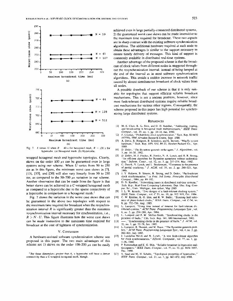
Fig. 7. 6 versus U when R = 40 s for hexagonal mesh, R = 130 s for hypercube. (a) Hexagonal mesh. (b) Hypercube.
wrapped hexagonal mesh and hypercube topologies. Clearly, skews on the order 100 p s can be guaranteed even in large systems using our scheme. When U varies from 50 to 250 ms as in this figure, the minimum worst case skews in [7], [13], [lS], and [20] will also vary linearly from SO to 250 ms, as compared to the SO-700 p s variation in our scheme. Another observation that can be made from the figure is that better skews can be achieved in a C-wrapped hexagonal mesh as compared to a hypercube due to the sparse connectivity of a hypercube in comparison to a hexagonal mesh.2
Fig. 7 shows the variation in the worst case skews that can be guaranteed in the above two topologies with respect to the maximum time required for broadcast when the resynchro- nization interval R is significantly greater than the minimum resynchronization interval necessary for synchronization, i.e., R > N . U . This figure illustrates how the worst case skews can be made insensitive to the maximum time required for broadcast at the cost of tightness of synchronization.
V. CONCLUSION
A hardware-assisted software synchronization scheme was proposed in this paper. The two main advantages of this scheme are 1) skews on the order 100-200 p s can be easily
*For those dimensions greater than 6, a hypercube will have a denser connectivity than a C-wrapped hexagonal mesh, though.
achieved even in large partially-connected distributed systems, 2) the guaranteed worst case skews can be made insensitive to the maximum time required for broadcast. These two aspects are in sharp contrast with the existing software synchronization algorithms. The additional hardware required at each node to obtain these advantages is similar to the support necessary to ensure timely delivery of messages. This kind of support is commonly available in distributed real-time systems.
Another advantage of the proposed scheme is that the broad- cast of clock values from different nodes is staggered through- out the resynchronization interval, instead of being lumped at the end of the interval as in most software synchronization algorithms. This avoids a sudden increase in network traffic caused by almost simultaneous broadcast of clock values from all nodes.
A possible drawback of our scheme is that it is only suit- able for topologies that support efficient reliable broadcast mechanisms. This is not a serious problem, however, since most fault-tolerant distributed systems require reliable broad- cast mechanisms for various other regions. Consequently, the scheme proposed in this paper has high potential for synchro- nizing large distributed systems.
REFERENCES M . 3 . Chen, K. G . Shin, and D. D. Kandlur, “Addressing, routing, and broadcasting in hexagonal mesh multiprocessors, ” IEEE Trans. Comput., vol. 39, no. I , pp. 10-18, Jan. 1990. F. Cristian, “Probabilistic clock synchronization,” Tech. Rep. RJ 6432 (62550), IBM Almaden Research Center, Sept. 1988. A. Davis, R. Hodgson, B. Schediwy, and K. Stevens, “Mayfly system hardware,” Tech. Rep. HPL-SAL-89-23, Hewlett-Packard Co., Apr. 1989. D. Dolev, “The Byzantine generals strike again,” J . Algorithms, vol. 3 , pp. 14-30, 1982. D. Dolev, M. J. Fischer, R. Fowler, N . A. Lynch, and H. R. Strong, “An efficient algorithm for Byzantine agreement without authentica- tion,” Inform. Contr., vol. 52, no. 3 , pp. 257-274, Mar. 1982. C. Dwork, N. Lynch, and L. Stockmeyer, “Consensus in the presence of partial synchrony,” J . ACM, vol. 35, no. 2, pp. 288-323, Apr. 1988. J. Y. Halpern, B. Simons, R. Strong, and D. Dolev, “Fault-tolerant clock synchronization,” in Proc. 3rd Symp. Principles Distributed Comput., 1984, pp. 89-102. D. D. Kandlur, “Networking issues in distributed real-time systems,” Tech. Rep., Real-Time Computing Laboratory, Dep. Elec. Eng. Com- put. Sci., Univ. Michigan, Ann Arbor, May 1989. J. L. W. Kessels, “Two designs of a fault-tolerant clocking system,” IEEE Trans. Cornput., vol. C-33, no. 10, pp. 912-919, Oct. 1984. C. M. Krishna, K. G . Shin, and R. W. Butler, “Ensuring fault toler- ance of phase-locked clocks,” IEEE Trans. Comput., vol. C-34, no.
L. Lamport, “Using time instead of timeout for fault-tolerant dis- tributed systems,” ACM Trans. Programming Languages Syst., vol. 6, no. 2, pp. 254-280, Apr. 1984. L. Lamport and P. M . Melliar-Smith, “Synchronizing clocks in the presence of faults,” CSL Tech. Rep. 141, SRI International, 1982. - , “Synchronizing clocks in the presence of faults,” J . ACM, vol. 32, no. I , pp. 52-78, Jan. 1985. L. Lamport, R. Shostak, and M. Pease, “The Byzantine generals prob- Iem,”ACM Trans. Programming Languages Syst., vol. 4, no. 3, pp.
J. Lundelius-Welch and N. Lynch, “A new fault-tolerant algorithm for clock synchronization,” Inform. Computat., vol. 77, no. 1, pp. 1-36, 1988. P. Ramanathan and K. G. Shin, “Reliable broadcast in hypercube mul- ticomputers,” IEEE Trans. Comput., vol. 37, no. 12, pp. 1654-1657, Dec. 1988. Y. Saad and M. H. Schultz, “Topological properties of hypercubes,” IEEE Trans. Comput., vol. 37, no. 7, pp. 867-872, July 1988.
8, pp. 752-756, Aug. 1985.
382-401, July 1982.

524 IEEE TRANSACTIONS ON COMPUTERS, VOL. 39, NO. 4. APRIL 1990
[18] C. L. Seitz, “The Cosmic Cube,” IEEE Trans. Comput., vol. C-34, P. Ramanathan received the B. Tech degree from no. 1, pp. 22-33, Jan. 1985. K. G. Shin and P. Ramanathan, “Clock synchronization of a large mul- tiprocessor system in the presence of malicious faults,” IEEE Trans. Cornput., vol. C-36, no. 1, pp. 2-12, Jan. 1987. T. K. Srikanth and S. Toueg, “Optimal clock synchronization,” J . ACM, vol. 34, no. 3. pp. 626-645, July 1987. K. S. Stevens, “The communication framework for a distributed en- semble architecture,” AI Tech. Rep. 47, Schlumberger Research Lab.. Feb. 1986. N. Vasanthavada and P. N. Marinos. “Synchronization of fault-tolerant clocks in the presence of malicious failures. ” IEEE Trans. Cornput,, vol. 37, no. 4, pp. 440-448, Apr. 1988. C. L. Yang and G . M. Masson, “A distributed algorithm for fault diagnosis in systems with soft failures,” IEEE Trans. Cornput.. vol. 37, no. 11, pp. 1476-1480, Nov. 1988. H. Kopetz and W. Ochsenreiter. “Clock synchronization in distributed real-time systems,” IEEE Trans. Cornput., vol. C-36, no. 8 , pp,
[19]
[20]
[21]
[22]
[23]
[24]
933-940, Aug. 1987.
the Indian Institute of Technology, Bombay, in 1984, and the M S E and Ph D degrees from the University of Michigan. Ann Arbor, in 1986 and 1989. respectively
From 1984 to 1989 he wd\ a Research Awstdnt in the Department of Electrical Engineering and Com- puter Science at the University of Michigan. Ann Arbor Currently, he is an Assistant Profecsor of Electrical and Computer Engineering at University of Wisconsin, Madison His research interests in-
clude fault-tolerant computing, distributed real-time computing, VLSI design, and computer architecture
Dilip D. Kandlur, for a photograph and biography, see the January 1990 issue of this TRANFACTIONS, p 18
Kang G . Shin (S’75-M’78-SM’83), for a photograph and biography. see the January 1990 issue of thls TRANSACTION^, p 18


![Clock Synchronization in WSN: from Traditional Estimation ...ycwu/Clock Synchronization in WSN_overvi… · Pairwise Synchronization: Gaussian case [1] • Synchronize node j to node](https://img.pdfslide.net/doc/110x75/5f8929217e699f4e040a8be7/clock-synchronization-in-wsn-from-traditional-estimation-ycwuclock-synchronization.jpg)