Embed Size (px)
Citation preview

Hardware Installation Manual
Version 6.6 February 2013
Document #: LTRT-10281
Mediant™ 850 MSBR
Multi-Service Business Router
SIP Protocol


Version 6.6 3 February 2013
Hardware Installation Manual Contents
Table of Contents 1 Introduction ......................................................................................................... 9
2 Unpacking the Device ...................................................................................... 11
3 Physical Description ........................................................................................ 13
3.1 Physical Dimensions .............................................................................................. 13 3.2 Front Panel Description .......................................................................................... 13
3.2.1 Ports and Buttons.................................................................................................... 13 3.2.2 LEDs ....................................................................................................................... 16
3.2.2.1 LAN Interface LED ................................................................................... 16 3.2.2.2 Power-over-Ethernet LAN LED ............................................................... 16 3.2.2.3 Wi-Fi LED ................................................................................................ 16 3.2.2.4 WAN LED ................................................................................................ 17 3.2.2.5 FXS LED .................................................................................................. 17 3.2.2.6 FXO LED ................................................................................................. 18 3.2.2.7 BRI LED ................................................................................................... 18 3.2.2.8 E1/T1 LED ............................................................................................... 18 3.2.2.9 Operational Status LED ........................................................................... 19 3.2.2.10 Power LED ............................................................................................... 19
3.3 Rear Panel Description .......................................................................................... 20
4 Attaching the Wi-Fi Antennas .......................................................................... 23
5 Mounting the Device ........................................................................................ 25
5.1 Desktop Mounting .................................................................................................. 25 5.2 19-Inch Rack Mounting .......................................................................................... 26
5.2.1 Using a Pre-installed Rack Shelf ............................................................................ 26 5.2.2 Using Mounting Brackets ........................................................................................ 27
6 Cabling the Device ........................................................................................... 29
6.1 Grounding the Device ............................................................................................. 29 6.2 Connecting to WAN ................................................................................................ 30
6.2.1 Copper Gigabit Ethernet Cabling ............................................................................ 30 6.2.2 Fiber-Optic Gigabit Ethernet Cabling ...................................................................... 31 6.2.3 SHDSL WAN Cabling ............................................................................................. 32 6.2.4 ADSL/2+ and VDSL2 WAN Cabling ....................................................................... 33 6.2.5 3G/3.5G Cellular WAN USB Modem Cabling ......................................................... 35
6.3 Connecting to LAN ................................................................................................. 36 6.4 Connecting PoE-Enabled Clients to LAN Ports ...................................................... 37 6.5 FXS Interfaces ........................................................................................................ 38
6.5.1 Connecting to Analog Devices ................................................................................ 39 6.5.2 Connecting the Analog Lifeline ............................................................................... 40
6.6 ISDN BRI Interfaces ............................................................................................... 41 6.6.1 Connecting to BRI Lines ......................................................................................... 41 6.6.2 Connecting the PSTN Fallback for BRI Lines ......................................................... 42
6.7 Connecting ISDN PRI (E1/T1) Trunks .................................................................... 43 6.8 Connecting the Serial Interface to a PC ................................................................. 44 6.9 Connecting a USB Storage Device ........................................................................ 45 6.10 Connecting the OSN Server ................................................................................... 46 6.11 Connecting to a Power Supply ............................................................................... 48

Hardware Installation Manual 4 Document #: LTRT-10281
Mediant 850 MSBR
7 Maintenance ...................................................................................................... 49
7.1 Replacing the Power Fuse ..................................................................................... 49
A Notice for Installing CentOS Version 4.7 on OSN Server .............................. 51

Version 6.6 5 February 2013
Hardware Installation Manual Contents
List of Figures Figure 3-1: Front Panel .......................................................................................................................... 13 Figure 3-2: Rear Panel .......................................................................................................................... 20 Figure 4-1: Attaching Antennas on Rear Panel ..................................................................................... 23 Figure 5-1: Location for Applying Rubber Foot ...................................................................................... 25 Figure 5-2: Mounting Bracket (Right) ..................................................................................................... 27 Figure 5-3: Attaching the Mounting Brackets ........................................................................................ 27 Figure 6-1: Earthing the Device ............................................................................................................. 29 Figure 6-2: Cabling the WAN Copper GbE Port .................................................................................... 31 Figure 6-3: Removing Protective Dust Plug .......................................................................................... 32 Figure 6-4: Cabling the Fiber-Optic WAN GbE Port .............................................................................. 32 Figure 6-5: Cabling the SHDSL WAN Port ............................................................................................ 33 Figure 6-6: Cabling the xDSL WAN Port ............................................................................................... 34 Figure 6-7: Plugging the 3G Cellular Modem into the USB Port ........................................................... 35 Figure 6-8: Cabling the LAN Ports ......................................................................................................... 36 Figure 6-9: RJ-11 Connector Pinouts for FXS Interface ........................................................................ 38 Figure 6-10: Connecting FXS Interfaces ............................................................................................... 38 Figure 6-11: RJ-11 Connector Pinouts for FXO Interface ..................................................................... 39 Figure 6-12: Connecting FXO Interfaces ............................................................................................... 39 Figure 6-13: RJ-11 Connector Pinouts for FXS Lifeline ........................................................................ 40 Figure 6-14: Cabling FXS Lifeline .......................................................................................................... 40 Figure 6-15: RJ-45 Connector Pinouts for BRI Ports ............................................................................ 41 Figure 6-16: Cabling BRI Ports .............................................................................................................. 41 Figure 6-17: Cabling (Ports 1 and 2) PSTN Fallback ............................................................................ 42 Figure 6-18: RJ-48c Connector Pinouts for E1/T1 ................................................................................ 43 Figure 6-19: Cabling E1/T1 Ports .......................................................................................................... 43 Figure 6-20: RS-232 Cable Adapter ...................................................................................................... 44 Figure 6-21: Cabling Serial Port ............................................................................................................ 44 Figure 6-22: Connecting USB Storage Device ...................................................................................... 45 Figure 6-23: Cabling OSN Server Ports ................................................................................................ 46 Figure 6-24: Connecting to the Power Supply ....................................................................................... 48 Figure 7-1: Opening the Fuse Cavity ..................................................................................................... 49 Figure 7-2: Removing the Power Fuse .................................................................................................. 49

Hardware Installation Manual 6 Document #: LTRT-10281
Mediant 850 MSBR
List of Tables Table 3-1: Physical Dimensions ............................................................................................................ 13 Table 3-2: Front-Panel Description of Ports and Buttons ...................................................................... 14 Table 3-3: LAN LED Description ............................................................................................................ 16 Table 3-4: PoE LAN LED Description .................................................................................................... 16 Table 3-5: Wi-Fi LED Description .......................................................................................................... 16 Table 3-6: WAN LED Description .......................................................................................................... 17 Table 3-7: FXS LED Description ............................................................................................................ 17 Table 3-8: FXO LED Description ........................................................................................................... 18 Table 3-9: BRI LED Description ............................................................................................................. 18 Table 3-10: E1/T1 LED Description ....................................................................................................... 18 Table 3-11: STATUS LED Description .................................................................................................. 19 Table 3-12: POWER LED Description ................................................................................................... 19 Table 3-13: Rear Panel Description ....................................................................................................... 20 Table 6-1: RJ-45 Connector Pinouts for Copper GbE WAN ................................................................. 30 Table 6-2: RJ-45 Connector Pinouts for SHDSL ................................................................................... 32 Table 6-3: RJ-11 Connector Pinouts for xDSL ...................................................................................... 34 Table 6-4: RJ-45 Connector Pinouts for GbE/FE with PoE ................................................................... 36 Table 6-5: RJ-45 to DB-9 Serial Cable Connector Pinouts ................................................................... 44 Table 7-1: Allowed Fuses for the Device ............................................................................................... 49

Version 6.6 7 February 2013
Hardware Installation Manual Notices
Notice This Hardware Installation Manual describes the hardware installation for AudioCodes Mediant 850 Multi-Service Business Router (MSBR). Information contained in this document is believed to be accurate and reliable at the time of printing. However, due to ongoing product improvements and revisions, AudioCodes cannot guarantee accuracy of printed material after the Date Published nor can it accept responsibility for errors or omissions. Before consulting this document, check the corresponding Release Notes regarding feature preconditions and/or specific support in this release. In cases where there are discrepancies between this document and the Release Notes, the information in the Release Notes supersedes that in this document. Updates to this document and other documents as well as software files can be downloaded by registered customers at http://www.audiocodes.com/downloads.
© Copyright 2013 AudioCodes Ltd. All rights reserved. This document is subject to change without notice.
Date Published: February-17-2013
Trademarks AudioCodes, AC, AudioCoded, Ardito, CTI2, CTI², CTI Squared, HD VoIP, HD VoIP Sounds Better, InTouch, IPmedia, Mediant, MediaPack, NetCoder, Netrake, Nuera, Open Solutions Network, OSN, Stretto, TrunkPack, VMAS, VoicePacketizer, VoIPerfect, VoIPerfectHD, What’s Inside Matters, Your Gateway To VoIP and 3GX are trademarks or registered trademarks of AudioCodes Limited. All other products or trademarks are property of their respective owners.
WEEE EU Directive Pursuant to the WEEE EU Directive, electronic and electrical waste must not be disposed of with unsorted waste. Please contact your local recycling authority for disposal of this product.
Customer Support Customer technical support and service are generally provided by AudioCodes’ Distributors, Partners, and Resellers from whom the product was purchased. For technical support for products purchased directly from AudioCodes, or for customers subscribed to AudioCodes Customer Technical Support (ACTS), contact [email protected].
Abbreviations and Terminology Each abbreviation, unless widely used, is spelled out in full when first used. Throughout this manual, unless otherwise specified, the term device refers to Mediant 850 MSBR.

Hardware Installation Manual 8 Document #: LTRT-10281
Mediant 850 MSBR
Related Documentation
Document Name
SIP Release Notes
Mediant 850 MSBR SIP User's Manual
MSBR Series CLI Reference Guide for System and VoIP Functionalities
MSBR Series CLI Reference Guide for Data Functionality
Notes and Warnings
Note: Open source software may have been added and/or amended for this product. For further information, please visit our website at http://audiocodes.com/support or contact your AudioCodes sales representative.
Caution Electrical Shock Do not open or disassemble this device. The device carries high voltage and contact with internal components may expose you to electrical shock and bodily harm.
Warning: The device must be installed and serviced only by qualified service personnel.
Warning: The device is an indoor unit and therefore, must be installed only indoors.
Warning: For deployment in Finland, Sweden and Norway, the device must be installed ONLY in restricted access locations that are compliant with ETS 300253 guidelines where equipotential bonding has been implemented.
Warning: Disconnect the device from the mains and Telephone Network Voltage (TNV) before servicing.
Documentation Feedback AudioCodes continually strives to produce high quality documentation. If you have any comments (suggestions or errors) regarding this document, please fill out the Documentation Feedback form on our Web site at http://www.audiocodes.com/downloads.

Version 6.6 9 February 2013
Hardware Installation Manual 1. Introduction
1 Introduction This document provides a hardware description of the Mediant 800 MSBR (hereafter referred to as device) and step-by-step procedures for mounting and cabling the device. The device provides the following interfaces: Optional telephony interfaces:
• Single or dual E1/T1 port (over single copper wire pair) • Up to 8 BRI ports (supporting up to 16 voice channels) • Up to 12 FXS ports • FXS Lifeline on FXS Port 1, maintaining PSTN connectivity upon power failure.
For the combined FXS/FXO configuration, one Lifeline is available; for the 12-FXS configuration, up to three Lifelines are available.
• Up to 12 FXO ports Optional LAN interfaces:
• Up to 12 Ethernet LAN ports: ♦ Up to 4 RJ-45 10/100/1000Base-T (Gigabit) ports ♦ Up to 8 RJ-45 10/100Base-TX (Fast Ethernet) ports Power over Ethernet (PoE) is supported on all LAN ports, complying with IEEE 802.3af-2003 and EEE 802.3at-2003. Various power budgets are supported for PoE on the LAN ports.
• Wireless LAN 802.11n (Wi-Fi) access point at 2.4 GHz and 5 GHz Tx / Rx, enabling data rates of up to 300 Mbps. The Wi-Fi interface also supports 802.11b/802.11g backward compatibility, allowing interoperability of multiple devices with different types of Wi-Fi.
Two USB ports for an optional, 3G cellular WAN modem and/or USB storage services Integrated Gigabit Ethernet (GE) Unshielded Twisted Pair (UTP) interface port, with an
option of one or two additional WAN interfaces of the following types (factory assembled option): • GE UTP • Optical Fiber SFP form factor, supporting 100 Mbps and 1000 Mbps Ethernet • ADSL2+ / VDSL2 (RJ-11 port interfaces) • SHDSL, supporting up to four wire-pairs (two RJ-11 port interfaces) • 1 x Ethernet copper WAN port (10/100/1000Base-T) • 3G Cellular WAN access (primary or backup) using a USB modem
RJ-45 serial interface port OSN server platform for hosting third-party applications such as an IP PBX. The
following OSN server platforms are available (depending on ordered model): • OSN1: Intel® Atom™ 1.6 GHz processor, with 1GB or 2GB RAM (depending on
Mediant 800 model) and a single storage hard disk drive (SATA storage) • OSN2: Intel® Celeron® 847E (2x 1.1 GHz), 2 MB L2 Cache, Intel® HM65 Second
Generation
Note: For information on configuring the device, refer to the device's User’s Manual.

Hardware Installation Manual 10 Document #: LTRT-10281
Mediant 850 MSBR
Reader's Notes

Version 6.6 11 February 2013
Hardware Installation Manual 2. Unpacking the Device
2 Unpacking the Device Follow the procedure below for unpacking the carton in which the device was shipped.
To unpack the device: 1. Open the carton and carefully remove packing materials. 2. Remove the chassis from the carton. 3. Check that there is no equipment damage. 4. Ensure that in addition to the chassis, the package contains the following items:
• Four anti-slide bumpers for desktop installation • Two mounting brackets for 19-inch rack mounting • One FXS Lifeline splitter cable adapter (only for models with FXS interfaces) • Three Wi-Fi antennas (depending on ordered model) • Serial cable adapter • One AC power cable
5. Check, retain and process any documents. If there are any damaged or missing items, notify your AudioCodes sales representative.

Hardware Installation Manual 12 Document #: LTRT-10281
Mediant 850 MSBR
Reader's Notes

Version 6.6 13 February 2013
Hardware Installation Manual 3. Physical Description
3 Physical Description This section provides a physical description of the device.
3.1 Physical Dimensions The device's physical dimensions and weight are listed in the table below:
Table 3-1: Physical Dimensions
Physical Specification Value
Dimensions (H x W x D) 32 x 34.5 cm (12.6 x 13.6 inches) x 1U
Weight 2.5 kg (5.5 lb)
3.2 Front Panel Description The front panel provides the telephony port interfaces, various networking ports, reset pinhole button, and LEDs.
3.2.1 Ports and Buttons The device's front panel is shown in the figure below and described in the subsequent table.
Figure 3-1: Front Panel
Note: The figure above is used only as an example. The number and type of port
interfaces depends on the ordered model.

Hardware Installation Manual 14 Document #: LTRT-10281
Mediant 850 MSBR
Table 3-2: Front-Panel Description of Ports and Buttons
Item # Label Description
1 POWER / STATUS / Wi-Fi
LEDs indicating the status of the power, reboot/initialization, and Wireless LAN interface (depending on ordered model). For more information, see Section 3.2.2 on page 16.
2 FXS / FXO / BRI / Digital
Telephony port interfaces that can include one or a combination of the following, depending on the ordered model: • FXS port interfaces (RJ-11) • FXO port interfaces (RJ-11) • ISDN BRI port interfaces (RJ-45) • E1/T1 port interfaces (RJ-48) Notes: • The FXS/FXO interfaces support loop-start signalling (indoor
only). • For supported hardware configuration options, refer to the
Release Notes. 3 // Reset pinhole button for resetting the device and optionally, for
restoring the device to factory defaults. To restore the device to factory defaults, do the following: With a paper clip or any other similar pointed object, press and
hold down the pinhole button for at least 12 seconds, but no longer than 25 seconds.
4 GE (Copper GbE) V/ADSLoPOTS
SHDSL GE SFP (Optic Fiber)
One or two optional, additional WAN interfaces. One copper GE Two copper GEs One SFP module (dual mode, supports 100 or 1000 Mbps) One copper GE and SFP module Two SFP modules One SHDSL Two SHDSL One AVDSL Two AVDSL One SHDSL and AVDSL One copper GE and AVDSL One copper GE and SHDSL One SFP and AVDSL One SFP and SHDSL Note: For available WAN configurations, contact your AudioCodes sales representative.
5 GE 0/0 Gigabit Ethernet (10/100/1000Base-T) copper WAN interface (RJ-45), provided for all models.

Version 6.6 15 February 2013
Hardware Installation Manual 3. Physical Description
Item # Label Description
6 GE Up to four Gigabit Ethernet (10/100/1000Base-T) LAN ports for connecting IP phones, computers, or switches. These ports support half- and full-duplex modes, auto-negotiation, and straight or crossover cable detection. These ports also support Power over Ethernet (PoE), complying with the IEEE 802.3af-2003 and IEEE 802.3at standards. The ports automatically detect the presence of IEEE 802.3 compliant devices. The maximum wattage available per port is 15.4W for IEEE 802.3af-2003 and 30W for IEEE 802.3at. The maximum wattage available for all ports (GE and FE) combined is 50W or 120W (depending on model). Note: PoE support is a customer ordered feature.
7 FE Eight Fast Ethernet (10/100Base-TX) RJ-45 LAN ports for connecting IP phones, computers, or switches. These ports support half- and full-duplex modes, auto-negotiation, and straight or crossover cable detection. These ports also support PoE, complying with the IEEE 802.3af-2003 standard. The ports automatically detect the presence of IEEE 802.3af-compliant devices. The maximum wattage available per port is 15.4W. The maximum wattage available for all ports (GE and FE) combined is 120W.
8 CONSOLE RJ-45 port for RS-232 serial communication.
9 USB/WWAN Two USB ports that can be used for connecting the following optional equipment: 3G cellular WAN modem for primary or backup WAN. External USB hard drive or flash disk (disk on key) for USB
storage capabilities.

Hardware Installation Manual 16 Document #: LTRT-10281
Mediant 850 MSBR
3.2.2 LEDs The front panel provides various LEDs depending on the device's hardware configuration (e.g., the available telephony interfaces). These LEDs are described in the subsequent subsections.
3.2.2.1 LAN Interface LED Each LAN port provides a LED (located on its left) for indicating LAN operating status, as described in the table below.
Table 3-3: LAN LED Description
LED Color
LED State
Description
Green On Ethernet link established.
Flashing Data is being received or transmitted.
- Off No Ethernet link.
3.2.2.2 Power-over-Ethernet LAN LED Each LAN port provides a LED (located on its right) for indicating PoE status, as described in the table below.
Table 3-4: PoE LAN LED Description
LED Color
LED State
Description
Yellow
On LAN port is transferring power (i.e., PoE is activated) to the connected equipment (e.g. IP phone).
Fast Flashing
Overload or short circuit is detected on the port output lines - PoE is not activated.
Slow Flashing
A valid PoE load is connected to the port, but the device has insufficient power to supply the required power load - PoE is not activated.
- Off No power load is present on the port output lines - PoE is not activated.
3.2.2.3 Wi-Fi LED The Wi-Fi LED indicates the Wi-Fi link status, as described in the table below.
Table 3-5: Wi-Fi LED Description
LED Color LED State Description
Green On Wi-Fi is activated.
Flashing Traffic on the wireless LAN.
- Off Wi-Fi is not configured.

Version 6.6 17 February 2013
Hardware Installation Manual 3. Physical Description
3.2.2.4 WAN LED The WAN port provides a LED for indicating operating status, as described in the table below.
Table 3-6: WAN LED Description
LED Color
LED State
Description
Green On WAN link established.
Flashing Data is being received or transmitted.
- Off No WAN link.
- Off No power received by the device.
3.2.2.5 FXS LED Each FXS port provides a LED for indicating operating status, as described in the table below.
Table 3-7: FXS LED Description
LED Color
LED State
Description
Green On Phone is off-hooked.
Flashing Rings the extension line.
Red On Error - malfunction in line or out of service due to Serial Peripheral Interface (SPI) failure.
- Off Phone is on hook.
- Off No power received by the device.

Hardware Installation Manual 18 Document #: LTRT-10281
Mediant 850 MSBR
3.2.2.6 FXO LED Each FXO port provides a LED for indicating operating status, as described in the table below.
Table 3-8: FXO LED Description
LED Color
LED State
Description
Green On FXO line is off-hooked toward the PBX.
Flashing Ring signal detected from the PBX.
Red On Error - malfunction in line or out of service due to Serial Peripheral Interface (SPI) failure.
- Off Line is on hook.
- Off No power received by the device.
3.2.2.7 BRI LED Each BRI port provides a LED for indicating operating status, as described in the table below:
Table 3-9: BRI LED Description
Color State Description
Green On Physical layer (Layer 1) is synchronized (normal operation).
Red On Physical layer (Layer 1) is not synchronized.
- Off Trunk is not active.
3.2.2.8 E1/T1 LED Each trunk port provides a LED for indicating operating status, as described in the table below:
Table 3-10: E1/T1 LED Description
Color State Description
Green On Trunk is synchronized (normal operation).
Red On Loss due to any of the following signals: LOS - Loss of Signal LOF - Loss of Frame AIS - Alarm Indication Signal (the Blue Alarm) RAI - Remote Alarm Indication (the Yellow Alarm)
- Off Failure / disruption in the AC power supply or the power is currently not being supplied to the device through the AC power supply entry.
Version 6.6 19 February 2013
Hardware Installation Manual 3. Physical Description
3.2.2.9 Operational Status LED The STATUS LED indicates the operating status, as described in the table below.
Table 3-11: STATUS LED Description
LED Color
LED State
Description
Green On The device is operational.
Flashing The device is rebooting.
Red On Boot failure.
3.2.2.10 Power LED The POWER LED indicates the operating status, as described in the table below.
Table 3-12: POWER LED Description
LED Color
LED State
Description
Green On Power is received by the device.
- Off No power received by the device.

Hardware Installation Manual 20 Document #: LTRT-10281
Mediant 850 MSBR
3.3 Rear Panel Description The device's rear panel is shown in the figure below and described in the subsequent table.
Figure 3-2: Rear Panel
Note: The figure above is used only as an example. The OSN server ports and Wi-Fi
antennas are available only if customer ordered.
Table 3-13: Rear Panel Description
Item # Label Description
1 OSN USB Three USB ports (Standard-A type) for connecting computer peripherals (e.g., mouse and keyboard). These are used when implementing the OSN. Note: These ports are available only if the device is equipped with the OSN server (customer ordered).
2 OSN VGA 15-Pin DB-type female VGA port for connecting to a monitor (screen). This port is used when implementing the OSN. Note: This port is available only if the device is equipped with the OSN server (customer ordered).
3 - Reset button for resetting the OSN server.
4 GE 1 GE 2
Two 10/100/1000Base-T Ethernet ports (RJ-45) for connecting directly to the OSN server. For example, one port can be connected to the LAN (to IP Phones) and the second port to the WAN interface (to an IP PBX).
5
Protective earthing screw.

Version 6.6 21 February 2013
Hardware Installation Manual 3. Physical Description
Item # Label Description
6 100-240V~1.5A 50-60Hz
3-Prong AC power supply entry.
7 - Wi-Fi antennas, providing wireless LAN 802.11n (Wi-Fi) access point at 2.4 GHz and 5 GHz Tx / Rx, enabling data rates of up to 300 Mbps. The Wi-Fi interface also supports 802.11b/802.11g backward compatibility, allowing interoperability of multiple devices with different types of Wi-Fi.

Hardware Installation Manual 22 Document #: LTRT-10281
Mediant 850 MSBR
Reader’s Notes

Version 6.6 23 February 2013
Hardware Installation Manual 4. Attaching the Wi-Fi Antennas
4 Attaching the Wi-Fi Antennas For models ordered with wireless LAN interface, the device is shipped with three unattached Wi-Fi antennas. You can attach any number of these antennas, according to your network requirements. Once attached, you can position each antenna in the vertical and/or horizontal plane for optimal transmission and reception.
Notes:
• Wi-Fi interface is a customer ordered item. • Attach antennas before mounting the device. It may be difficult to attach
the antennas once the device is mounted.
To attach the Wi-Fi antennas to the device: 1. Manually screw the antennas on to the SMA coaxial RF connector located on the rear
panel, as shown in the figure below:
Figure 4-1: Attaching Antennas on Rear Panel
2. Orient the antennas as desired for optimal wireless performance. The antenna can be
orientated in the vertical and horizontal planes. For best performance, it is recommended that the antennas be perpendicular (90 degrees) to the floor. In other words, orient the antennas straight up.

Hardware Installation Manual 24 Document #: LTRT-10281
Mediant 850 MSBR
Reader's Notes

Version 6.6 25 February 2013
Hardware Installation Manual 5. Mounting the Device
5 Mounting the Device The device can be mounted in one of the following ways: Placed on a desktop – see Section 5.1 on page 25 Installed in a standard 19-inch rack – see Section 5.2 on page 26
Warning: Do not place any equipment directly on top of the device or adjacent to its sides (at least 13-cm separation). In addition, if you are mounting the device in a 19-inch rack, ensure that at least a 3U separation is maintained between the device and other mounted devices or equipment.
5.1 Desktop Mounting The device can be placed on a desktop when its four anti-slide bumpers (supplied) are attached to the underside of the device.
To attach the anti-slide rubber bumpers to the device: 1. Flip the device over so that its underside faces up. 2. Locate the four anti-slide grooves on the underside - one in each corner. 3. Peel off the adhesive, anti-slide rubber feet and stick one in each anti-slide groove.
Figure 5-1: Location for Applying Rubber Foot
4. Flip the device over again so that it rests on the rubber feet and place it in the required
position on a desktop.
Hardware Installation Manual 26 Document #: LTRT-10281
Mediant 850 MSBR
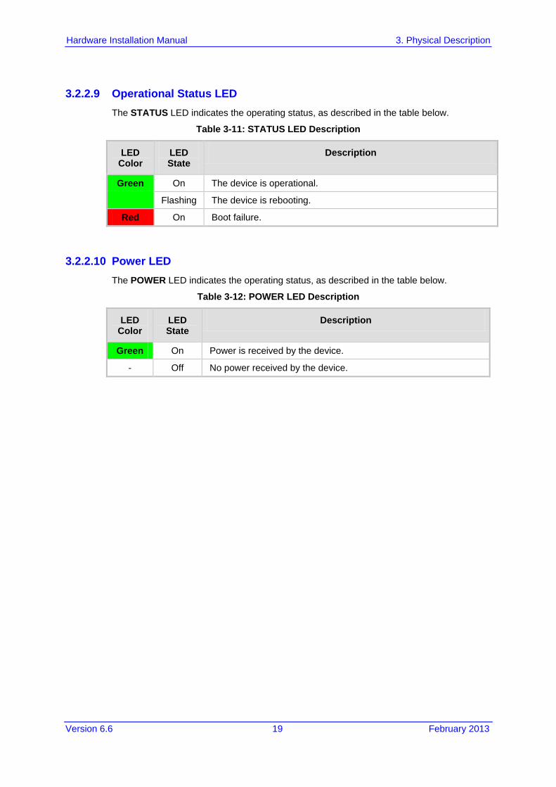
5.2 19-Inch Rack Mounting The device can be installed in a standard 19-inch rack by implementing one of the following mounting methods: Placing it on a pre-installed shelf in a 19-inch rack – see Section 5.2.1 on page 26 Attaching it directly to the rack’s frame using the device's mounting brackets (supplied)
that need to be attached to the chassis – see Section 5.2.2 on page 27
Rack Mount Safety Instructions
When installing the chassis in a rack, implement the following safety instructions: • Elevated Operating Ambient Temperature: If installed in a closed or multi-
unit rack assembly, the operating ambient temperature of the rack environment may be greater than room ambient temperature. Therefore, consideration should be given to installing the equipment in an environment with maximum ambient temperature (Tma) of 40°C (104°F).
• Reduced Air Flow: Installation of the equipment in a rack should be such that the amount of air flow required for safe operation on the equipment is not compromised.
• Mechanical Loading: Mounting of the equipment in the rack should be such that a hazardous condition is not achieved due to uneven mechanical loading.
• Circuit Overloading: Consideration should be given to the connection of the equipment to the supply circuit and the effect that overloading of the circuits might have on over-current protection and supply wiring. Appropriate consideration of equipment nameplate ratings should be used when addressing this concern.
• Reliable Earthing: Reliable earthing of rack-mounted equipment should be maintained. Particular attention should be given to supply connections other than direct connections to the branch circuit (e.g., use of power strips). For earthing the device, see Section 6.1 on page 29.
5.2.1 Using a Pre-installed Rack Shelf The procedure below describes how to place the device on a pre-installed shelf in a 19-inch rack.
To mount the device on a pre-installed shelf in the rack: 1. Before installing it in the rack, ensure that you have a pre-installed rack shelf on which
the device can be placed. 2. Place the device on the pre-installed shelf in the rack.
Version 6.6 27 February 2013
Hardware Installation Manual 5. Mounting the Device
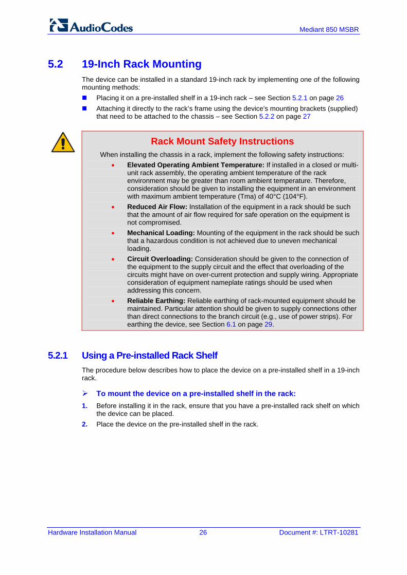
5.2.2 Using Mounting Brackets The procedure below describes how to mount the device in a 19-inch rack. Rack mounting involves placing the device on a pre-installed rack shelf and then attaching the device's mounting brackets (to the device and rack frame). The purpose of the mounting brackets is to secure the device to the rack.
Figure 5-2: Mounting Bracket (Right)
Note: The mounting brackets for 19-inch rack mounting are a customer-ordered item.
To mount the device in a 19-inch rack using mounting brackets: 1. Attach the two mounting brackets (supplied) to each side of the device's chassis, using
the supplied screws, as shown in the figure below:
Figure 5-3: Attaching the Mounting Brackets
2. Place the device on a pre-installed shelf in the rack. 3. Attach the ends of the mounting brackets (that you installed in Step 1) to the vertical
track of the rack's frame, using standard 19-inch rack bolts (not supplied).

Hardware Installation Manual 28 Document #: LTRT-10281
Mediant 850 MSBR
Reader's Notes

Version 6.6 29 February 2013
Hardware Installation Manual 6. Cabling the Device
6 Cabling the Device This section describes the cabling of the device, which includes the following: Grounding (earthing) the device – see Section 6.1 on page 29 Connecting to the WAN – see Section 6.2 on page 29 Connecting to the LAN – see Section 6.3 on page 36 Connecting PoE-enabled equipment – see Section 6.4 on page 37 Connecting the FXS interfaces – see Section 6.5 on page 37 Connecting to Analog Devices – see Section 6.5.1 on page 39 Connecting the Analog Lifeline – see Section 6.5.2 on page 40 Connecting to BRI lines – see Section 6.6.1 on page 41 Connecting the PSTN Fallback for BRI Lines – see Section 6.6.2 on page 42 Connecting E1/T1 trunks – see Section 6.7 on page 43 Connecting to a computer for serial communication – see Section 6.8 on page 44 Connecting a USB storage device – see Section 6.9 on page 41 Connecting the OSN server – see Section 6.10 on page 46 Connecting to the power supply – see Section 6.11 on page 48
6.1 Grounding the Device The device must be connected to earth (grounded) using an equipment-earthing conductor.
Protective Earthing The equipment is classified as Class I EN60950 and UL60950 and must be earthed at all times. For Finland: "Laite on liltettava suojamaadoituskoskettimilla varustettuun pistorasiaan." For Norway: "Apparatet rna tilkoples jordet stikkontakt." For Sweden: "Apparaten skall anslutas till jordat uttag."
To earth the device: 1. Connect an electrically earthed strap of 16 AWG wire (minimum) to the chassis'
earthing screw (located on the rear panel), using the supplied washer. 2. Connect the other end of the strap to a protective earthing. This should be in
accordance with the regulations enforced in the country of installation. Figure 6-1: Earthing the Device

Hardware Installation Manual 30 Document #: LTRT-10281
Mediant 850 MSBR
6.2 Connecting to WAN This section provides a description on how to cable the WAN port. The cabling procedure depends on the ordered WAN interface: Copper Gigabit Ethernet (GbE) – see Section 6.2.1 on page 30 Fiber-optic GbE – see Section 6.2.2 on page 31 SHDSL – see Section 6.2.3 on page 32 ADSL/2+ and VDSL2 – see Section 6.2.4 on page 33 3G Cellular WAN modem – see Section 6.2.5 on page 35
Note: The device supports multiple WAN redundancies, where multiple WAN interfaces can serve as backups for the primary or a backup WAN interface. For example, if the main WAN interface is GbE and it fails, the device switches over to the SHDSL WAN interface. If this WAN interface also fails, the device switches over to the 3G WAN interface, and so on. For configuring WAN redundancy, refer to the MSBR Series CLI Reference Guide.
6.2.1 Copper Gigabit Ethernet Cabling The procedure below describes how to connect the copper Gigabit Ethernet RJ-45 port to the WAN. Before you do this, ensure that the RJ-45 connector pinouts of the used cable are as follows:
Table 6-1: RJ-45 Connector Pinouts for Copper GbE WAN
Pin Signal Name
1 Ethernet signal pair
2
3 Ethernet signal pair
6
4 Ethernet signal pair
5
7 Ethernet signal pair
8
Shield Chassis ground

Version 6.6 31 February 2013
Hardware Installation Manual 6. Cabling the Device
To connect the WAN copper GbE port: 1. Connect one end of a straight-through RJ-45 Ethernet cable to the RJ-45 port labeled
WAN (located on the front panel).
Figure 6-2: Cabling the WAN Copper GbE Port
2. Connect the other end of the cable to the Ethernet WAN network (e.g., ADSL or Cable
modem).
6.2.2 Fiber-Optic Gigabit Ethernet Cabling The device provides up to two pairs of 155-Mbps optical small form-factor pluggable (SFP) transceiver modules. The SFP and the cable can be ordered from AudioCodes. For supported SFPs, please contact AudioCodes. The procedure below describes how to connect the GbE ports over fiber-optic cables.
Caution Laser This device contains a Class 1 LED/Laser emitting device, as defined by 21CFR 1040 and IEC825. Do not stare directly into the beam or into fiber optic terminations as this can damage your eyesight.
Care in Handling Fiber Optic Cabling: 1. Excessive bending of the Fiber Optic Cable can cause distortion and signal
losses. 2. Ensure the minimum bending radius recommended by the Fiber Optic Cable
supplier. 3. Incoming optic cabling from the network infrastructure can originate from the top
of the rack or from another shelf within the rack. Preserve the minimum-bending ratio indicated by the cable manufacturer.
4. To ensure full high-availability capabilities, the configuration of the interface to the IP backbone must include certain redundant features from which two separate fiber optic cables are entering the device.

Hardware Installation Manual 32 Document #: LTRT-10281
Mediant 850 MSBR
To connect the fiber-optic WAN GbE port: 1. Remove the protective dust plug from the SFP transceiver module.
Figure 6-3: Removing Protective Dust Plug
2. Connect a cable with LC-type plugs to the SFP transceivers (labeled GE SFP).
Figure 6-4: Cabling the Fiber-Optic WAN GbE Port
6.2.3 SHDSL WAN Cabling The SHDSL port has four wire-pairs, supporting up to four SHDSL WAN ports on a single physical connector (RJ-45). SHDSL port specifications: Conforms to ITU G.991.2 Annexes A, B, E, F and G SHDSL Up to 5,696 Kbps over a single wire pair Up to 22,784 Kbps over four wire pairs bonding, according to SHDSL.bis (ITU G.991.2
Annexes F, G) EFM and ATM support Wetting current support on the CPE side, according to G991.2 Supports both Central Office (CO) and CPE (wetting current on CO - excluded) TC-PAM 16/32 line code Before you connect the SHDSL port, ensure that the RJ-45 connector pinouts on the cable used is as follows:
Table 6-2: RJ-45 Connector Pinouts for SHDSL
Pin Function
4 CH0-TIP
5 CH0-RING
1 CH1-TIP
2 CH1-RING
3 CH2-TIP

Version 6.6 33 February 2013
Hardware Installation Manual 6. Cabling the Device
Pin Function
6 CH2-RING
7 CH3-TIP
8 CH3-RING
To connect the WAN SHDSL port: 1. Connect an RJ-45 SHDSL cable to the device’s SHDSL WAN port (labeled SHDSL).
Figure 6-5: Cabling the SHDSL WAN Port
2. Connect the other end of the cable to the access point.
6.2.4 ADSL/2+ and VDSL2 WAN Cabling The ADSL/2+ and VDSL2 (xDSL) WAN port provides a single xDSL interface through its RJ-11 port. The specifications of the xDSL interface include the following: ADSL/2+:
• RFC 2684 in Routed (IPoA) and Bridged (ETHoA) modes, supporting LLC-SNAP and VC-Multiplexed encapsulations over AAL5
• ATM UNI 4.1 compliant • UBR, CBR, VBR classes of service • RFC 2364 PPPoA • RFC 2516 PPPoE over ATM • Up to 8 PVCs
VDSL2: • ITU G.991.2 Annex E for Ethernet, also known as EFM or 2Base-TL, as defined in
IEEE 802.3ah • 802.1q VLANs over EFM • PPPoE

Hardware Installation Manual 34 Document #: LTRT-10281
Mediant 850 MSBR
Before you connect the xDSL port, ensure that the RJ-11 connector pinouts on the cable used is as follows:
Table 6-3: RJ-11 Connector Pinouts for xDSL
Pin Function
3 CH0-P/TIP
4 CH0-N/RING
1 Not connected
2 Not connected
3 Not connected
6 Not connected
To connect the WAN xDSL WAN port: 1. Connect an RJ-11 cable connector to the device’s xDSL WAN port (labeled
V/ADSLoPOTS).
Figure 6-6: Cabling the xDSL WAN Port
2. Connect the other end of the cable to the access point.
Note: The xDSL filter/splitter should be provided by your service provider.

Version 6.6 35 February 2013
Hardware Installation Manual 6. Cabling the Device
6.2.5 3G/3.5G Cellular WAN USB Modem Cabling The device supports 3G cellular WAN connection using a USB modem. The 3G cellular WAN interface can be used as the primary WAN interface or as an optional WAN backup when the primary WAN (e.g., WAN Ethernet) fails. The WAN connection type is a point-to-point protocol (PPP) over cellular. The device supports the following 3G cellular USB modems: ZTE MF626 ZTE MF637 Alcatel X220 Huawei E182E Huawei E160 Huawei E173 Sierra Wireless AirCard 308
To connect the 3G cellular WAN modem: Plug a 3G cellular USB modem into any one of the USB ports located on the front
panel, labeled USB/WWAN.
Figure 6-7: Plugging the 3G Cellular Modem into the USB Port
Note: For configuring the 3G cellular WAN support, refer to the User's Manual.

Hardware Installation Manual 36 Document #: LTRT-10281
Mediant 850 MSBR
6.3 Connecting to LAN The device provides up to four Gigabit Ethernet (10/100/1000Base-T) LAN RJ-45, ports and eight RJ-45 10/100Base-TX (Fast Ethernet) LAN ports for connection to the LAN (e.g., computers, switches, and IP phones). These ports support half- and full-duplex modes, auto-negotiation, and straight or crossover cable detection. The LAN ports can also support PoE. For connecting PoE-enabled equipment to the LAN ports, see Section 6.4 on page 37. The RJ-45 connector pinouts are described in the table below:
Table 6-4: RJ-45 Connector Pinouts for GbE/FE with PoE
Pin Signal Name
1 Ethernet signal pair (10/100/1000Base-T) and PoE NEG
2
3 Ethernet signal pair (10/100/1000Base-T) and PoE POS
6
4 Ethernet signal pair (1000Base-T)
5
7 Ethernet signal pair (1000Base-T)
8
Shield Chassis ground
To connect the device to the LAN: 1. Connect one end of a straight-through RJ-45 Cat 5e or Cat 6 cable to the RJ-45 port
labeled GE (for Gigabit Ethernet ports) and/or FE (for Fast Ethernet ports).
Figure 6-8: Cabling the LAN Ports
2. Connect the other end of the cable to the Gigabit Ethernet network (for the GE ports)
and/or Fast Ethernet network (for the FE ports).

Version 6.6 37 February 2013
Hardware Installation Manual 6. Cabling the Device
6.4 Connecting PoE-Enabled Clients to LAN Ports The LAN ports support PoE according to the IEEE 802.3af-2003 and IEEE 802.3at standards. The ports can transfer electrical power, along with the usual data, over the Ethernet cable to connected equipment (e.g., IP phone) capable of receiving PoE. The LAN ports automatically detect the presence of IEEE 802.3 compliant equipment. Upon plugging in a PoE client to one of the ports, the device also automatically detects the class to which the client belongs and consequently, the maximum power allowed: IEEE 802.3af-2003: The device can supply up to 15.4W per port, and a total budget of
50W or 120W (depending on Mediant 800 model) for all ports: • Class 0: configurable, up to 15.4W – refer to the User's Manual for more
information • Class 1: up to 4W • Class 2: up to 7W • Class 3: up to 15.4W
IEEE 802.3at – Class 4: The device can supply up to 30W per port to the connected equipment and a total budget of 50W, 120W, or 200W (depending on Mediant 800 model) for all ports.
If the plugged-in client is detected as Class 0, the device saves the user-defined wattage from the total wattage budget (default is 15.4W). If the plugged-in client is detected as Class 1, Class 2, or Class 3, the device saves 4W, 7W, or 15.4W respectively from the total wattage budget. If the power budget has been exhausted and a new client is plugged in, no power is available to this client. Note that the power is always taken off the total budget according to the class detected, regardless of what is actually consumed per port. PoE is supplied on Pins 4,5: (+), and pins 7,8: (-).
Notes:
• PoE support is a customer ordered feature. • You can enable or disable PoE per port. For more information, refer to
the User's Manual. • Upon device startup, PoE is enabled on all ports. • You can configure the maximum port power consumption (up to 15.4W)
used when the plugged-in client is detected as Class 0. You can also enable Class 4 PoE per port. For more information, refer to the User's Manual.
To connect PoE-enabled equipment to the PoE-enabled LAN ports: 1. Connect one end of a straight-through RJ-45 Cat 5e or Cat 6 cable to a LAN port
enabled with PoE. 2. Connect the other end of the cable to PoE-enabled equipment (e.g., an IP Phone).
Hardware Installation Manual 38 Document #: LTRT-10281
Mediant 850 MSBR
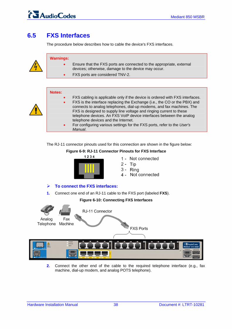
6.5 FXS Interfaces The procedure below describes how to cable the device's FXS interfaces.
Warnings: • Ensure that the FXS ports are connected to the appropriate, external
devices; otherwise, damage to the device may occur. • FXS ports are considered TNV-2.
Notes: • FXS cabling is applicable only if the device is ordered with FXS interfaces. • FXS is the interface replacing the Exchange (i.e., the CO or the PBX) and
connects to analog telephones, dial-up modems, and fax machines. The FXS is designed to supply line voltage and ringing current to these telephone devices. An FXS VoIP device interfaces between the analog telephone devices and the Internet.
• For configuring various settings for the FXS ports, refer to the User's Manual.
The RJ-11 connector pinouts used for this connection are shown in the figure below:
Figure 6-9: RJ-11 Connector Pinouts for FXS Interface
To connect the FXS interfaces: 1. Connect one end of an RJ-11 cable to the FXS port (labeled FXS).
Figure 6-10: Connecting FXS Interfaces
2. Connect the other end of the cable to the required telephone interface (e.g., fax
machine, dial-up modem, and analog POTS telephone).

Version 6.6 39 February 2013
Hardware Installation Manual 6. Cabling the Device
6.5.1 Connecting to Analog Devices The procedure below describes how to cable the device's FXO interfaces.
Warnings: • To protect against electrical shock and fire, use a minimum 26-AWG wire to
connect FXO ports to the PSTN. • Ensure that the FXO ports are connected to the appropriate, external
devices; otherwise, damage to the device may occur. • FXO ports are considered TNV-3.
Notes: • FXO cabling is applicable only if the device is ordered with FXO interfaces. • FXO is the interface replacing the analog telephone and connects to a
Public Switched Telephone Network (PSTN) line from the Central Office (CO) or to a Private Branch Exchange (PBX). The FXO is designed to receive line voltage and ringing current, supplied from the CO or the PBX (similar to an analog telephone). An FXO VoIP device interfaces between the CO/PBX line and the Internet.
• For configuring various settings for the FXO ports, refer to the User's Manual.
The RJ-11 connector pinouts used for this connection are shown in the figure below:
Figure 6-11: RJ-11 Connector Pinouts for FXO Interface
To connect the FXO interfaces: 1. Connect one end of an RJ-11 cable to the FXO port (labeled FXO).
Figure 6-12: Connecting FXO Interfaces
2. Connect the other end of the cable to the required telephone interface: (e.g., telephone
exchange analog lines or PBX extensions).

Hardware Installation Manual 40 Document #: LTRT-10281
Mediant 850 MSBR
6.5.2 Connecting the Analog Lifeline The device's analog Lifeline phone feature redirects IP calls to the PSTN upon a power outage or loss of IP network connectivity, thereby guaranteeing call continuity. The Lifeline is provided by FXS Port # 1. This port connects to the analog POTS phone and the PSTN / PBX using an RJ-11 splitter cable. The Lifeline splitter connects pins 1 and 4 to another source of an FXS port, and pins 2 and 3 to the POTS phone. The RJ-11 connector pinouts are shown in the figure below.
Figure 6-13: RJ-11 Connector Pinouts for FXS Lifeline
To cable the FXS Lifeline: 1. Connect the Lifeline Splitter (supplied) to FXS Port 1. 2. On the Lifeline splitter cable, do the following:
a. Connect the analog telephone to Port A. b. Connect an analog PSTN line to Port B.
Figure 6-14: Cabling FXS Lifeline
Notes:
• Analog Lifeline cabling is applicable only if the device is ordered with FXS interfaces.
• The number of supported Lifelines depends on the device’s hardware configuration. For the combined FXS/FXO configuration, one Lifeline is available; for the 12-FXS configuration, up to three Lifelines are available.
• The scenarios upon which Lifeline is activated is configured by the LifeLineType ini file parameter (for more information, refer to the User's Manual).

Version 6.6 41 February 2013
Hardware Installation Manual 6. Cabling the Device
6.6 ISDN BRI Interfaces
6.6.1 Connecting to BRI Lines The device provides up to four BRI S/T ports. These ports connect to ISDN terminal equipment such as ISDN telephones. Each BRI port can be configured either as termination equipment/user side (TE) or network termination/network side (NT). Up to eight terminal equipment (TE) devices can be connected per BRI S/T port, using an ISDN S-bus that provides eight ISDN ports. When configured as NT, the BRI port drives a nominal voltage of 38 V with limited current supply of up to 100 mA. The connector pinouts for the BRI port when configured as TE or NT are shown below:
Figure 6-15: RJ-45 Connector Pinouts for BRI Ports
Warning: To protect against electrical shock and fire, use a 26 AWG min wire to connect the BRI ports to the PSTN.
Note: BRI cabling is applicable only if the device is ordered with BRI interfaces.
To connect the BRI ports: 1. Connect the BRI cable to the device's BRI RJ-45 port. 2. Connect the other end of the cable to your ISDN telephone or PBX/PSTN switch.
Figure 6-16: Cabling BRI Ports

Hardware Installation Manual 42 Document #: LTRT-10281
Mediant 850 MSBR
6.6.2 Connecting the PSTN Fallback for BRI Lines The device supports a PSTN Fallback feature for BRI lines, whereby if a power outage or IP connectivity problem (e.g., no ping) occurs, IP calls are re-routed to the PSTN. This guarantees call continuity. PSTN Fallback is supported if the device houses one or more BRI modules, where each BRI module provides two or four spans. In the event of a PSTN fallback, the BRI module's metallic relay switch automatically connects line Port 1 (I) to Port 2 (II) of the BRI module. For example, if a PBX trunk is connected to Port 1 and the PSTN network is connected to Port 2, when PSTN Fallback is activated, calls from the PBX are routed directly to the PSTN through Port 2.
To connect the BRI line interfaces for 1+1 PSTN Fallback: 1. Connect line 1 to a PBX. 2. On the same BRI module, connect line 2 to the PSTN.
Figure 6-17: Cabling (Ports 1 and 2) PSTN Fallback
Notes:
• PSTN Fallback is supported only on the BRI module. • PSTN Fallback is supported only between ports on the same BRI module. • The scenarios that trigger PSTN Fallback (i.e., power outage and/or IP
network loss) are configured by the TrunkLifeLineType parameter. For more information, see the User's Manual.
• This PSTN Fallback feature has no relation to the PSTN Fallback Software Upgrade Key.
Version 6.6 43 February 2013
Hardware Installation Manual 6. Cabling the Device
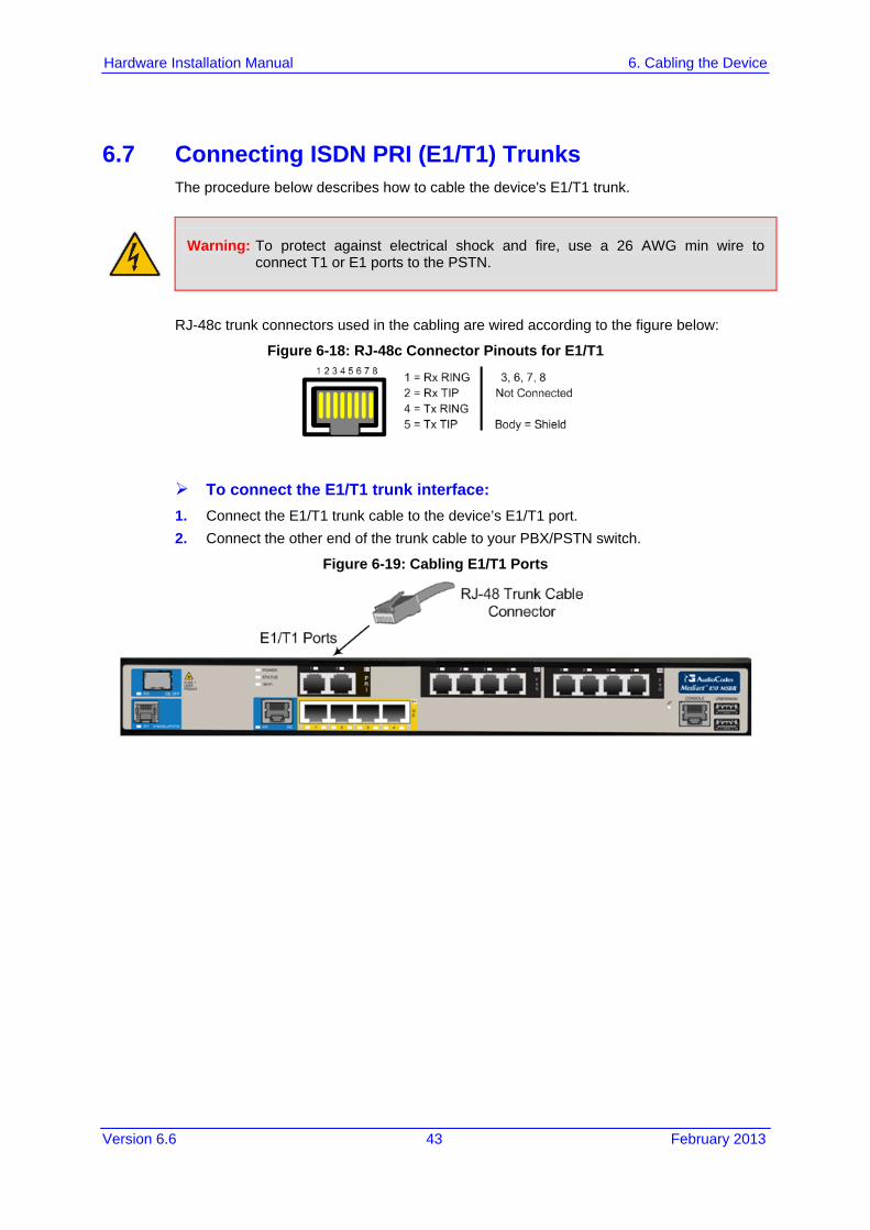
6.7 Connecting ISDN PRI (E1/T1) Trunks The procedure below describes how to cable the device's E1/T1 trunk.
Warning: To protect against electrical shock and fire, use a 26 AWG min wire to connect T1 or E1 ports to the PSTN.
RJ-48c trunk connectors used in the cabling are wired according to the figure below:
Figure 6-18: RJ-48c Connector Pinouts for E1/T1
To connect the E1/T1 trunk interface: 1. Connect the E1/T1 trunk cable to the device’s E1/T1 port. 2. Connect the other end of the trunk cable to your PBX/PSTN switch.
Figure 6-19: Cabling E1/T1 Ports

Hardware Installation Manual 44 Document #: LTRT-10281
Mediant 850 MSBR
6.8 Connecting the Serial Interface to a PC The device provides an RS-232 serial interface port on its front panel. The serial cable adapter used for connecting the RS-232 interface is shown below:
Figure 6-20: RS-232 Cable Adapter
Table 6-5: RJ-45 to DB-9 Serial Cable Connector Pinouts
RJ-45 DB-9 Female
1 8
2 6
3 2
4 5
5 5
6 3
7 4
8 7
To connect the device's serial interface port to a PC: 1. Connect the end of the cable providing the RJ-45 connector to the device's serial port
located on the front panel (labeled CONSOLE).
Figure 6-21: Cabling Serial Port
2. Connect the other end of the cable providing the 9-pin DB connector to the COM RS-
232 communication port on your computer.

Version 6.6 45 February 2013
Hardware Installation Manual 6. Cabling the Device
6.9 Connecting a USB Storage Device The device supports USB storage capabilities, using an external USB hard drive or flash disk (disk on key) connected to the device's USB port. The storage capabilities include the following: Saving network captures to the USB. This is done using the following CLI command:
# debug capture data physical stop usb
Updating the device's firmware from the USB. This is done using the following CLI command: # copy firmware from usb://firmware.cmp
Updating the device's configuration from the USB. This is done using the following CLI command: # copy voice-configuration from usb://board.ini
Saving current configuration to the USB. This is done using the following CLI command: # copy voice-configuration to usb://board.ini
To connect the USB storage device: Connect the USB storage device to one of the USB ports located on the front panel
(labeled USB/WWAN).
Figure 6-22: Connecting USB Storage Device
Note: Only a single USB storage (formatted to FAT/FAT32) operation is supported at any given time.
Hardware Installation Manual 46 Document #: LTRT-10281
Mediant 850 MSBR
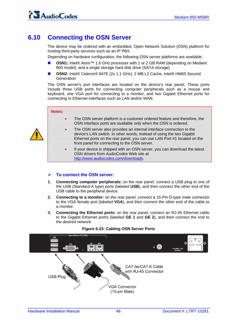
6.10 Connecting the OSN Server The device may be ordered with an embedded, Open Network Solution (OSN) platform for hosting third-party services such as an IP PBX. Depending on hardware configuration, the following OSN server platforms are available: OSN1: Intel® Atom™ 1.6 GHz processor with 1 or 2 GB RAM (depending on Mediant
800 model), and a single storage hard disk drive (SATA storage) OSN2: Intel® Celeron® 847E (2x 1.1 GHz), 2 MB L2 Cache, Intel® HM65 Second
Generation The OSN server's port interfaces are located on the device's rear panel. These ports include three USB ports for connecting computer peripherals such as a mouse and keyboard, one VGA port for connecting to a monitor, and two Gigabit Ethernet ports for connecting to Ethernet interfaces such as LAN and/or WAN.
Notes:
• The OSN server platform is a customer ordered feature and therefore, the OSN interface ports are available only when the OSN is ordered.
• The OSN server also provides an internal interface connection to the device's LAN switch. In other words, instead of using the two Gigabit Ethernet ports on the rear panel, you can use LAN Port #1 located on the front panel for connecting to the OSN server.
• If your device is shipped with an OSN server, you can download the latest OSN drivers from AudioCodes Web site at http://www.audiocodes.com/downloads.
To connect the OSN server: 1. Connecting computer peripherals: on the rear panel, connect a USB plug to one of
the USB (Standard-A type) ports (labeled USB), and then connect the other end of the USB cable to the peripheral device.
2. Connecting to a monitor: on the rear panel, connect a 15-Pin D-type male connector to the VGA female port (labeled VGA), and then connect the other end of the cable to a monitor.
3. Connecting the Ethernet ports: on the rear panel, connect an RJ-45 Ethernet cable to the Gigabit Ethernet port/s (labeled GE 1 and GE 2), and then connect the end to the desired network.
Figure 6-23: Cabling OSN Server Ports

Version 6.6 47 February 2013
Hardware Installation Manual 6. Cabling the Device
4. Connect the device to power. 5. Insert the operating system CD media (Linux or Microsoft Windows) into the CD-ROM
drive. 6. Continue according to the CD's installation instructions.
To reset the OSN server: Insert a sharp-pointed object (such as a drawing pin) into the Reset pinhole and then
extract it after a second; the OSN server performs a reset.

Hardware Installation Manual 48 Document #: LTRT-10281
Mediant 850 MSBR
6.11 Connecting to a Power Supply The device receives power from a standard alternating current (AC) electrical outlet. The connection is made using the supplied AC power cord.
Warnings:
• The device must be connected to a socket-outlet providing a protective earthing connection.
• Use only the AC power cord that is supplied with the device. • For replacing the power fuse, see Section 7 on page 49.
To connect the device to the power supply: 1. Connect the line socket of the AC power cord (supplied) to the device's AC power
socket (labeled 100-240V 1.5A ~50-60 Hz), located on the rear panel.
Figure 6-24: Connecting to the Power Supply
2. Connect the plug at the other end of the AC power cord to a standard electrical outlet. Once you have cabled and powered-up the device, the POWER LED on the front panel lights up green. For a description of this LED, see Section 3.2.2.10 on page 19.

Version 6.6 49 February 2013
Hardware Installation Manual 7. Maintenance
7 Maintenance This section describes maintenance procedures.
7.1 Replacing the Power Fuse The device contains a fuse that protects the device from excessive current. The fuse is located on the rear panel, below the power socket. To replace the fuse, use only one of the following fuses described in the table below:
Table 7-1: Allowed Fuses for the Device
Manufacturer Manufacturer Part Number
BEL 5ET2.5-R
CONQUER UDL 2.50
LITTEFUSE 021302.5MXP
Caution For continuous protection, replace only with the same fuse type and rating fuse.
To replace the power fuse: 1. Unplug the power cord from the electrical outlet. 2. Using a small flathead screwdriver, gently pries open the fuse cavity as illustrated in
the figure below:
Figure 7-1: Opening the Fuse Cavity
3. Carefully remove the fuse from the fuse cavity.
Figure 7-2: Removing the Power Fuse

Hardware Installation Manual 50 Document #: LTRT-10281
Mediant 850 MSBR
4. Insert the new fuse securely into the fuse cavity until you hear a click sound. 5. Reconnect the power cord and verify that the Power LED is lit green.

Version 6.6 51 February 2013
Hardware Installation Manual A. Notice for Installing CentOS Version 4.7 on OSN Server
A Notice for Installing CentOS Version 4.7 on OSN Server This appendix provides important information when installing CentOS Ver. 4.7 Linux Distribution on the OSN server: When installing CentOS, ensure that you type linux irqpoll at the boot: prompt. For CentOS to identify the OSN server’s Gigabit Ethernet (GE) interfaces, do the
following: 1. Obtain the following files from AudioCodes:
♦ Binary compiled CentOS 4.7 driver for Intel e1000e Ethernet controller on Mediant 800 MSBR (e1000e.ko)
♦ Manual pages (e1000e.7.gz) 2. Copy the files to the /root directory. 3. Remove any old e1000e modules (if any) and install the new module and manual
pages: #> find /lib/modules/2.6.9-78.ELsmp –name e1000e.ko –exec rm –rf {}\; #> find /lib/modules/2.6.9-78.ELsmp –name e1000e.ko.gz –exec rm –rf {}\; #> install –D –m 644 /root/e1000e.ko /lib/modules/2.6.9-78.ELsmp/kernel/drivers/net/e1000e/e1000e.ko #> /sbin/depmod –a #> echo “alias eth1 e1000e” >> /etc/modprobe.conf #> echo “alias eth2 e1000e” >> /etc/modprobe.conf #> install –D –m 644 /root/e1000e.7.gz /usr/share/man/man7/e1000e.7.gz #> man –c –P`cat > /dev/null` e1000e #> modprobe e1000e
Note: The character #> depicts the CLI prompt and is not part of the command. 4. Restart networking, by running the following command:
#> service network restart
Note: The character #> depicts the CLI prompt (i.e., this is not part of the command). The final result should be as follows: Eth0 = r8169 (INTERNAL and not in use ) Eth1 = e1000e (GE LAN) Eth2 = e1000e (GE LAN)

Hardware Installation Manual
www.audiocodes.com