Embed Size (px)
Citation preview

EDS84DG752.Peb
Ä.Pebä
Hardware Manual
8400 motec 0.37 ... 7.5 kW
E84DGxxxxxxxxx
Decentralised frequency inverter
L-force Drives
Translation

0Fig. 0Tab. 0

Contents i
3EDS84DG752 EN 5.0
1 About this documentation 7. . . . . . . . . . . . . . . . . . . . . . . . . . . . . . . . . . . . . . . . . . . . . . . . . .
1.1 Validity information 7. . . . . . . . . . . . . . . . . . . . . . . . . . . . . . . . . . . . . . . . . . . . . . . . . .
1.2 Document history 8. . . . . . . . . . . . . . . . . . . . . . . . . . . . . . . . . . . . . . . . . . . . . . . . . . . .
1.3 Conventions used 9. . . . . . . . . . . . . . . . . . . . . . . . . . . . . . . . . . . . . . . . . . . . . . . . . . . .
1.4 Terms and abbreviations used 10. . . . . . . . . . . . . . . . . . . . . . . . . . . . . . . . . . . . . . . . . .
1.5 Notes used 11. . . . . . . . . . . . . . . . . . . . . . . . . . . . . . . . . . . . . . . . . . . . . . . . . . . . . . . . . .
2 Safety instructions 12. . . . . . . . . . . . . . . . . . . . . . . . . . . . . . . . . . . . . . . . . . . . . . . . . . . . . . . . .
2.1 General safety and application notes for Lenze controllers 12. . . . . . . . . . . . . . . . . .
2.2 General safety and application instructions for Lenze motors 15. . . . . . . . . . . . . . . .
2.3 Residual hazards 18. . . . . . . . . . . . . . . . . . . . . . . . . . . . . . . . . . . . . . . . . . . . . . . . . . . . .
3 Product description 19. . . . . . . . . . . . . . . . . . . . . . . . . . . . . . . . . . . . . . . . . . . . . . . . . . . . . . . .
3.1 System overview 19. . . . . . . . . . . . . . . . . . . . . . . . . . . . . . . . . . . . . . . . . . . . . . . . . . . . .
3.2 Device features 20. . . . . . . . . . . . . . . . . . . . . . . . . . . . . . . . . . . . . . . . . . . . . . . . . . . . . .
3.3 Identification 21. . . . . . . . . . . . . . . . . . . . . . . . . . . . . . . . . . . . . . . . . . . . . . . . . . . . . . . .
3.4 Type code 22. . . . . . . . . . . . . . . . . . . . . . . . . . . . . . . . . . . . . . . . . . . . . . . . . . . . . . . . . .3.4.1 Introducing information 22. . . . . . . . . . . . . . . . . . . . . . . . . . . . . . . . . . . . . . .3.4.2 The type codes 22. . . . . . . . . . . . . . . . . . . . . . . . . . . . . . . . . . . . . . . . . . . . . . .
3.5 Overview of control terminals 25. . . . . . . . . . . . . . . . . . . . . . . . . . . . . . . . . . . . . . . . . .
4 Technical data 26. . . . . . . . . . . . . . . . . . . . . . . . . . . . . . . . . . . . . . . . . . . . . . . . . . . . . . . . . . . .
4.1 General data and operating conditions 26. . . . . . . . . . . . . . . . . . . . . . . . . . . . . . . . .
4.2 Rated data 31. . . . . . . . . . . . . . . . . . . . . . . . . . . . . . . . . . . . . . . . . . . . . . . . . . . . . . . . . .4.2.1 Overview 31. . . . . . . . . . . . . . . . . . . . . . . . . . . . . . . . . . . . . . . . . . . . . . . . . . . .4.2.2 Operation at rated mains voltage 400 V 33. . . . . . . . . . . . . . . . . . . . . . . . . .4.2.3 Operation at increased rated power at 400 Vmains voltage 35. . . . . . . . .4.2.4 Operation with rated mains voltage 480 V 37. . . . . . . . . . . . . . . . . . . . . . . .
4.3 Switching frequency reduction 39. . . . . . . . . . . . . . . . . . . . . . . . . . . . . . . . . . . . . . . . .
4.4 Overcurrent operation 40. . . . . . . . . . . . . . . . . . . . . . . . . . . . . . . . . . . . . . . . . . . . . . . .
4.5 Terminal description 42. . . . . . . . . . . . . . . . . . . . . . . . . . . . . . . . . . . . . . . . . . . . . . . . . .4.5.1 Overview 42. . . . . . . . . . . . . . . . . . . . . . . . . . . . . . . . . . . . . . . . . . . . . . . . . . . .
4.6 Power terminals 44. . . . . . . . . . . . . . . . . . . . . . . . . . . . . . . . . . . . . . . . . . . . . . . . . . . . . .4.6.1 Mains connection 45. . . . . . . . . . . . . . . . . . . . . . . . . . . . . . . . . . . . . . . . . . . . .4.6.2 Motor connection 45. . . . . . . . . . . . . . . . . . . . . . . . . . . . . . . . . . . . . . . . . . . . .4.6.3 Motor temperature monitoring 45. . . . . . . . . . . . . . . . . . . . . . . . . . . . . . . . .4.6.4 Motor holding brake connection 45. . . . . . . . . . . . . . . . . . . . . . . . . . . . . . . .4.6.5 Connection of brake resistor 45. . . . . . . . . . . . . . . . . . . . . . . . . . . . . . . . . . . .
Contentsi
4 EDS84DG752 EN 5.0
4.7 Control terminals 46. . . . . . . . . . . . . . . . . . . . . . . . . . . . . . . . . . . . . . . . . . . . . . . . . . . . .4.7.1 Digital inputs 48. . . . . . . . . . . . . . . . . . . . . . . . . . . . . . . . . . . . . . . . . . . . . . . .4.7.2 Digital output 50. . . . . . . . . . . . . . . . . . . . . . . . . . . . . . . . . . . . . . . . . . . . . . . .4.7.3 Analog input 50. . . . . . . . . . . . . . . . . . . . . . . . . . . . . . . . . . . . . . . . . . . . . . . . .4.7.4 Connection of relay output 50. . . . . . . . . . . . . . . . . . . . . . . . . . . . . . . . . . . . .4.7.5 Communication connection 51. . . . . . . . . . . . . . . . . . . . . . . . . . . . . . . . . . . .
4.8 Dimensions 52. . . . . . . . . . . . . . . . . . . . . . . . . . . . . . . . . . . . . . . . . . . . . . . . . . . . . . . . . .4.8.1 Standard motor mounting 52. . . . . . . . . . . . . . . . . . . . . . . . . . . . . . . . . . . . .4.8.2 Wall mounting 53. . . . . . . . . . . . . . . . . . . . . . . . . . . . . . . . . . . . . . . . . . . . . . .
5 Installation 54. . . . . . . . . . . . . . . . . . . . . . . . . . . . . . . . . . . . . . . . . . . . . . . . . . . . . . . . . . . . . . .
5.1 Important notes 54. . . . . . . . . . . . . . . . . . . . . . . . . . . . . . . . . . . . . . . . . . . . . . . . . . . . . .
5.2 Safety instructions for the installation according to UL/CSA 57. . . . . . . . . . . . . . . . .
5.3 Safety instructions for the installation according to UL/CSA 58. . . . . . . . . . . . . . . . .
5.4 Installation according to EMC (installation of a CE-typical drive system) 59. . . . . . .5.4.1 Shielding 59. . . . . . . . . . . . . . . . . . . . . . . . . . . . . . . . . . . . . . . . . . . . . . . . . . . .5.4.2 Motor cable 60. . . . . . . . . . . . . . . . . . . . . . . . . . . . . . . . . . . . . . . . . . . . . . . . . .5.4.3 Control cables 61. . . . . . . . . . . . . . . . . . . . . . . . . . . . . . . . . . . . . . . . . . . . . . . .5.4.4 Detecting and eliminating EMC interferences 61. . . . . . . . . . . . . . . . . . . . .
5.5 Mechanical installation 62. . . . . . . . . . . . . . . . . . . . . . . . . . . . . . . . . . . . . . . . . . . . . . . .
5.6 Electrical installation 63. . . . . . . . . . . . . . . . . . . . . . . . . . . . . . . . . . . . . . . . . . . . . . . . . .5.6.1 Power connections 63. . . . . . . . . . . . . . . . . . . . . . . . . . . . . . . . . . . . . . . . . . . .5.6.2 Wiring of control connections 64. . . . . . . . . . . . . . . . . . . . . . . . . . . . . . . . . . .
5.7 Installation of 8400motec pre-assembled on the motor 66. . . . . . . . . . . . . . . . . . . .5.7.1 Plug at theWiring Unit 66. . . . . . . . . . . . . . . . . . . . . . . . . . . . . . . . . . . . . . . .5.7.2 Attaching the cable gland 67. . . . . . . . . . . . . . . . . . . . . . . . . . . . . . . . . . . . . .
5.8 Retrofitting the 8400motec controller 69. . . . . . . . . . . . . . . . . . . . . . . . . . . . . . . . . . .5.8.1 Preparing a motor for the 8400motec installation 69. . . . . . . . . . . . . . . . .5.8.2 Mounting theWiring Unit 70. . . . . . . . . . . . . . . . . . . . . . . . . . . . . . . . . . . . . .5.8.3 Mounting of the Communication Unit 71. . . . . . . . . . . . . . . . . . . . . . . . . . .5.8.4 Settings at the Drive Unit 72. . . . . . . . . . . . . . . . . . . . . . . . . . . . . . . . . . . . . .5.8.5 Mounting of the Drive Unit 72. . . . . . . . . . . . . . . . . . . . . . . . . . . . . . . . . . . . .
5.9 Measures when drive is used in IT systems 74. . . . . . . . . . . . . . . . . . . . . . . . . . . . . . .
5.10 Wall mounting of 8400motec controller 75. . . . . . . . . . . . . . . . . . . . . . . . . . . . . . . . .
6 Commissioning 76. . . . . . . . . . . . . . . . . . . . . . . . . . . . . . . . . . . . . . . . . . . . . . . . . . . . . . . . . . .
6.1 Before switching on 76. . . . . . . . . . . . . . . . . . . . . . . . . . . . . . . . . . . . . . . . . . . . . . . . . .
6.2 Quick commissioning 78. . . . . . . . . . . . . . . . . . . . . . . . . . . . . . . . . . . . . . . . . . . . . . . . .6.2.1 General configuration settings 79. . . . . . . . . . . . . . . . . . . . . . . . . . . . . . . . . .6.2.2 Commissioning steps 85. . . . . . . . . . . . . . . . . . . . . . . . . . . . . . . . . . . . . . . . . .
6.3 Handling of the keypad 86. . . . . . . . . . . . . . . . . . . . . . . . . . . . . . . . . . . . . . . . . . . . . . . .

Contents i
5EDS84DG752 EN 5.0
6.4 Overview of the commissioning steps with keypad 89. . . . . . . . . . . . . . . . . . . . . . . .6.4.1 Keypad control 89. . . . . . . . . . . . . . . . . . . . . . . . . . . . . . . . . . . . . . . . . . . . . . .6.4.2 Short overview of the parameters for quick commissioning 93. . . . . . . . . .
6.5 Setting with the diagnosis terminal (keypad) 94. . . . . . . . . . . . . . . . . . . . . . . . . . . . .
6.6 Diagnostics 95. . . . . . . . . . . . . . . . . . . . . . . . . . . . . . . . . . . . . . . . . . . . . . . . . . . . . . . . . .6.6.1 Drive diagnostics via the integrated display 95. . . . . . . . . . . . . . . . . . . . . . .6.6.2 Diagnostic codes 95. . . . . . . . . . . . . . . . . . . . . . . . . . . . . . . . . . . . . . . . . . . . .
7 Braking operation 96. . . . . . . . . . . . . . . . . . . . . . . . . . . . . . . . . . . . . . . . . . . . . . . . . . . . . . . . .
7.1 Braking operation without additional measures 96. . . . . . . . . . . . . . . . . . . . . . . . . . .
7.2 Braking operation with brake resistor 97. . . . . . . . . . . . . . . . . . . . . . . . . . . . . . . . . . . .7.2.1 Selection of the brake resistors 97. . . . . . . . . . . . . . . . . . . . . . . . . . . . . . . . . .7.2.2 Wiring of brake resistor 98. . . . . . . . . . . . . . . . . . . . . . . . . . . . . . . . . . . . . . . .
7.3 Operation with spring-applied brake 101. . . . . . . . . . . . . . . . . . . . . . . . . . . . . . . . . . . .7.3.1 Introduction 101. . . . . . . . . . . . . . . . . . . . . . . . . . . . . . . . . . . . . . . . . . . . . . . . .7.3.2 Wiring 101. . . . . . . . . . . . . . . . . . . . . . . . . . . . . . . . . . . . . . . . . . . . . . . . . . . . . .
8 Safety engineering 102. . . . . . . . . . . . . . . . . . . . . . . . . . . . . . . . . . . . . . . . . . . . . . . . . . . . . . . .
8.1 Introduction 102. . . . . . . . . . . . . . . . . . . . . . . . . . . . . . . . . . . . . . . . . . . . . . . . . . . . . . . . .
8.2 Important notes 103. . . . . . . . . . . . . . . . . . . . . . . . . . . . . . . . . . . . . . . . . . . . . . . . . . . . . .8.2.1 Hazard and risk analysis 104. . . . . . . . . . . . . . . . . . . . . . . . . . . . . . . . . . . . . . .8.2.2 Standards 104. . . . . . . . . . . . . . . . . . . . . . . . . . . . . . . . . . . . . . . . . . . . . . . . . . .
8.3 Basics for safety sensors 105. . . . . . . . . . . . . . . . . . . . . . . . . . . . . . . . . . . . . . . . . . . . . . .
8.4 Operating mode 106. . . . . . . . . . . . . . . . . . . . . . . . . . . . . . . . . . . . . . . . . . . . . . . . . . . . . .8.4.1 Introduction 106. . . . . . . . . . . . . . . . . . . . . . . . . . . . . . . . . . . . . . . . . . . . . . . . .8.4.2 Disconnecting paths 106. . . . . . . . . . . . . . . . . . . . . . . . . . . . . . . . . . . . . . . . . .8.4.3 Safety status 107. . . . . . . . . . . . . . . . . . . . . . . . . . . . . . . . . . . . . . . . . . . . . . . . .
8.5 Technical data 108. . . . . . . . . . . . . . . . . . . . . . . . . . . . . . . . . . . . . . . . . . . . . . . . . . . . . . .
8.6 Electrical installation 110. . . . . . . . . . . . . . . . . . . . . . . . . . . . . . . . . . . . . . . . . . . . . . . . . .
8.7 Certification 111. . . . . . . . . . . . . . . . . . . . . . . . . . . . . . . . . . . . . . . . . . . . . . . . . . . . . . . . .
9 Accessories (overview) 112. . . . . . . . . . . . . . . . . . . . . . . . . . . . . . . . . . . . . . . . . . . . . . . . . . . . .
9.1 Adapter plates (accessories) 112. . . . . . . . . . . . . . . . . . . . . . . . . . . . . . . . . . . . . . . . . . . .
9.2 Plug connectors 113. . . . . . . . . . . . . . . . . . . . . . . . . . . . . . . . . . . . . . . . . . . . . . . . . . . . . .
9.3 Internal brake resistors 114. . . . . . . . . . . . . . . . . . . . . . . . . . . . . . . . . . . . . . . . . . . . . . . .
9.4 External brake resistors 115. . . . . . . . . . . . . . . . . . . . . . . . . . . . . . . . . . . . . . . . . . . . . . .

Contentsi
6 EDS84DG752 EN 5.0
9.5 Communicationmodules 116. . . . . . . . . . . . . . . . . . . . . . . . . . . . . . . . . . . . . . . . . . . . . .9.5.1 CANopen 116. . . . . . . . . . . . . . . . . . . . . . . . . . . . . . . . . . . . . . . . . . . . . . . . . . . .9.5.2 PROFIBUS 116. . . . . . . . . . . . . . . . . . . . . . . . . . . . . . . . . . . . . . . . . . . . . . . . . . . .9.5.3 AS interface 116. . . . . . . . . . . . . . . . . . . . . . . . . . . . . . . . . . . . . . . . . . . . . . . . . .9.5.4 PROFINET 117. . . . . . . . . . . . . . . . . . . . . . . . . . . . . . . . . . . . . . . . . . . . . . . . . . .9.5.5 EtherCAT 117. . . . . . . . . . . . . . . . . . . . . . . . . . . . . . . . . . . . . . . . . . . . . . . . . . . .9.5.6 EtherNet/IP 117. . . . . . . . . . . . . . . . . . . . . . . . . . . . . . . . . . . . . . . . . . . . . . . . . .
9.6 Keypad 118. . . . . . . . . . . . . . . . . . . . . . . . . . . . . . . . . . . . . . . . . . . . . . . . . . . . . . . . . . . . .
9.7 Safety engineering 119. . . . . . . . . . . . . . . . . . . . . . . . . . . . . . . . . . . . . . . . . . . . . . . . . . .
10 Appendix 120. . . . . . . . . . . . . . . . . . . . . . . . . . . . . . . . . . . . . . . . . . . . . . . . . . . . . . . . . . . . . . . .
10.1 Total index 120. . . . . . . . . . . . . . . . . . . . . . . . . . . . . . . . . . . . . . . . . . . . . . . . . . . . . . . . . .

About this documentationValidity information
1
7EDS84DG752 EN 5.0
1 About this documentation
1.1 Validity information
Contents
This Hardware Manual informs you how to use the motec version of the 8400 controllerseries as directed.
Validity
Type Type designation from hardwareversion
from software version
8400 motec E84DGDVNxxxx2xS VA 01.00
Accessories of 8400 motec E84DG... -- --
Target group
This Hardware Manual is intended for all persons who design, install, commission, andadjust controllers of the 8400 Inverter Drives product range.
Tip!Information and tools concerning the Lenze products can be found in thedownload area underwww.lenze.com

About this documentationDocument history
1
8 EDS84DG752 EN 5.0
1.2 Document history
Material number Version Description
.Peb 5.0 12/2014 TD15 UL notes in French for CanadaEAC ConformityGeneral corrections
13410318 4.0 06/2012 TD15 General revision, supplements, and corrections
13394702 3.0 11/2011 TD15 Extension 4 ... 7.5 kW
13375479 2.0 04/2011 TD15 Extension 2.2 ... 3 kW, PROFINET, EtherCAT
13372091 1.1 01/2011 TD15 General revision, supplements, and corrections
13349634 1.0 09/2010 TD15 First edition

About this documentationConventions used
1
9EDS84DG752 EN 5.0
1.3 Conventions used
This documentation uses the following conventions to distinguish between differenttypes of information:
Spelling of numbers
Decimal separator Point In general, the decimal point is used.For instance: 1234.56
Warnings
UL warnings Given in English and French
UR warnings Text
Program name » « PC softwareFor example: »Engineer«, »Global DriveControl« (GDC)
Icons
Page reference Reference to another page with additionalinformationFor instance: 16 = see page 16
Documentation reference Reference to another documentation withadditional informationFor example: EDKxxx = seedocumentation EDKxxx

About this documentationTerms and abbreviations used
1
10 EDS84DG752 EN 5.0
1.4 Terms and abbreviations used
Term Meaning
Device size Used as generic term for a group of devices which have the same dimensions(depth, height and width) but different power ratings.
Standard device Used as generic term when actions and features are described which are verysimilar or the same for different versions or device sizes, e.g. mechanical installation or power terminals
DU Drive unit8400 motec controller
CU Communication unitOptional interfaces per I/O, fieldbus, safety system
WU Wiring unitReady-made motor connection, replaces the motor terminal box
Abbreviation Meaning
24O 24 V voltage supply for non-safe monitoring
Cat. Category according to EN 954-1 (valid until 30 November 2009)
DO Non-safe feedback output
F-PLC Safety PLC
GSDML File containing device-specific data to establish PROFINET communication
GSE File containing device-specific data to establish PROFIBUS communication
OFF state Signal status of the safety sensors when they are activated or respond
ON state Signal status of the safety sensors during normal operation
Opto supply Optocoupler supply for controlling the drivers
OSSD Output Signal Switching Device, tested signal output
PELV Protective Extra Low Voltage
PL Performance Level according to EN ISO 13849-1
PM P/N switching signal paths
PP P/P switching signal paths
PS PROFIsafe
PWM Pulse Width Modulation
S-Bus Safety bus
SD-In Safe input (Safe Digital Input)
SD-Out Safe output (Safe Digital Output)
SELV Safety Extra Low Voltage
SIA, SIB Safe Input, channel A or B, respectively
SIL Safety Integrity Level according to IEC 61508
SO Integrated safety option
n. c. Terminal not assigned
Abbreviation Safety function
STO Safe Torque OffFormer designation: safe standstill

About this documentationNotes used
1
11EDS84DG752 EN 5.0
1.5 Notes used
The following pictographs and signal words are used in this documentation to indicatedangers and important information:
Safety instructions
Structure of safety instructions:
Danger!(characterises the type and severity of danger)Note(describes the danger and gives information about how to prevent dangeroussituations)
Pictograph and signal word Meaning
Danger!Danger of personal injury through dangerous electrical voltage.Reference to an imminent danger that may result in death orserious personal injury if the corresponding measures are nottaken.
Danger!Danger of personal injury through a general source of danger.Reference to an imminent danger that may result in death orserious personal injury if the corresponding measures are nottaken.
Stop!Danger of property damage.Reference to a possible danger that may result in propertydamage if the corresponding measures are not taken.
Application notes
Pictograph and signal word Meaning
Note! Important note to ensure troublefree operation
Tip! Useful tip for simple handling
Reference to another documentation
Special safety instructions and application notes
Pictograph and signal word Meaning
Warnings! Safety note or application note for the operation according toUL or CSA requirements.The measures are required to meet the requirements accordingto UL or CSA. Warnings!

Safety instructionsGeneral safety and application notes for Lenze controllers
2
12 EDS84DG752 EN 5.0
2 Safety instructions
2.1 General safety and application notes for Lenze controllers
(in accordance with Low-Voltage Directive 2006/95/EC)
For your personal safety
Disregarding the following safety measures can lead to severe injury to persons anddamage to material assets:
ƒ Only use the product as directed.
ƒ Never commission the product in the event of visible damage.
ƒ Never commission the product before assembly has been completed.
ƒ Do not carry out any technical changes on the product.
ƒ Only use the accessories approved for the product.
ƒ Only use original spare parts from Lenze.
ƒ Observe all regulations for the prevention of accidents, directives and lawsapplicable on site.
ƒ Transport, installation, commissioning and maintenance work must only be carriedout by qualified personnel.
– Observe IEC 364 and CENELEC HD 384 or DIN VDE 0100 and IEC report 664 orDIN VDE 0110 and all national regulations for the prevention of accidents.
– According to this basic safety information, qualified, skilled personnel are personswho are familiar with the assembly, installation, commissioning, and operation ofthe product and who have the qualifications necessary for their occupation.
ƒ Observe all specifications in this documentation.
– This is the condition for safe and trouble-free operation and the achievement ofthe specified product features.
– The procedural notes and circuit details described in this documentation are onlyproposals. It’s up to the user to check whether they can be transferred to theparticular applications. Lenze Drives GmbH does not accept any liability for thesuitability of the procedures and circuit proposals described.
ƒ Depending on their degree of protection, some parts of the Lenze controllers(frequency inverters, servo inverters, DC speed controllers) and their accessorycomponents can be live, moving and rotating during operation. Surfaces can be hot.
– Non-authorised removal of the required cover, inappropriate use, incorrectinstallation or operation, creates the risk of severe injury to persons or damage tomaterial assets.
– For more information, please see the documentation.
ƒ High amounts of energy are produced in the controller. Therefore it is required towear personal protective equipment (body protection, headgear, eye protection, earprotection, hand guard).

Safety instructionsGeneral safety and application notes for Lenze controllers
2
13EDS84DG752 EN 5.0
Application as directed
Controllers are components which are designed for installation in electrical systems ormachines. They are not to be used as domestic appliances, but only for industrial purposesaccording to EN 61000-3-2.Whencontrollersare installed intomachines, commissioning (i.e. startingof theoperationas directed) is prohibited until it is proven that themachine complieswith the regulationsof the EC Directive 2006/42/EC (Machinery Directive); EN 60204 must be observed.Commissioning (i.e. starting of the operation as directed) is only allowed when there iscompliance with the EMC Directive (2004/108/EC).The controllers meet the requirements of the Low-Voltage Directive 2006/95/EC. Theharmonised standard EN 61800-5-1 applies to the controllers.The technical data and supply conditions can be obtained from the nameplate and thedocumentation. They must be strictly observed.Warning: Controllers are products which can be installed in drive systems of category C2accordingtoEN 61800-3. Theseproducts cancause radio interferences in residentialareas.In this case, special measures can be necessary.
Transport, storage
Please observe the notes on transport, storage, and appropriate handling.Observe the climatic conditions according to the technical data.
Installation
The controllers must be installed and cooled according to the instructions given in thecorresponding documentation.The ambient air must not exceed degree of pollution 2 according to EN 61800-5-1.Ensure proper handling and avoid excessive mechanical stress. Do not bend anycomponents and do not change any insulation distances during transport or handling. Donot touch any electronic components and contacts.Controllers contain electrostatic sensitive devices which can easily be damaged byinappropriate handling. Do not damage or destroy any electrical components since thismight endanger your health!
Electrical connection
When working on live controllers, observe the applicable national regulations for theprevention of accidents (e.g. VBG 4).The electrical installation must be carried out according to the appropriate regulations(e.g. cable cross-sections, fuses, PE connection). Additional information can be obtainedfrom the documentation.The documentation provides notes on EMC-compliant installation (shielding, earthing,filter arrangement, and laying of cables). Please also observe these notes when installingCE-labelled controllers. The manufacturer of the machine or plant is responsible for thecompliance with the required limit values associated with EMC legislation.Lenze controllers may cause a DC current in the PE conductor. If a residual current deviceis used as a protective means in the case of direct or indirect contact with a three-phasecontroller, a residual currentdeviceof typeBmustbeusedon thecurrent supply sideof thecontroller. If the controller has a single-phase supply, it is also permissible to use a residualcurrent device of type A. Apart from the use of a residual current device, other protectivemeasures can also be taken, such as isolation from the environment by double orreinforced insulation, or separation from the supply system by means of a transformer.
Safety instructionsGeneral safety and application notes for Lenze controllers
2
14 EDS84DG752 EN 5.0
Operation
If necessary, systems including controllers must be equipped with additional monitoringand protection devices according to the valid safety regulations (e.g. law on technicalequipment, regulations for the prevention of accidents). The controllers canbe adapted toyour application. Please observe the corresponding information given in thedocumentation.After the controller has been disconnected from the supply voltage, all live componentsand power terminals must not be touched immediately because capacitors can still becharged. Please observe the corresponding stickers on the controller.All protection covers and doors must be shut during operation.Notes for UL-approved systems with integrated controllers: UL warnings are notes thatonly apply to UL systems. The documentation contains special UL notes.
Safety functions
Certain controller versions support safety functions (e.g. ”Safe torque off”, formerly ”Safestandstill”) according to the requirements of the EC Directive ”Machinery” 2006/42/EC.The notes provided in the documentation on drive-based safetymust be strictly observed.
Maintenance and servicing
The controllers do not require anymaintenance if the prescribed operating conditions areobserved.
Disposal
Recycle metal and plastic materials. Ensure professional disposal of assembled PCBs.The product-specific safety and application notes given in these instructions must beobserved!

Safety instructionsGeneral safety and application instructions for Lenze motors
2
15EDS84DG752 EN 5.0
2.2 General safety and application instructions for Lenze motors
(According to: Low-Voltage Directive 2006/95/EC)
General
Low-voltage machines have hazardous live and rotating parts and possibly also hotsurfaces.
Synchronous machines induce voltages at open terminals during operation.
All operations concerning transport, connections, commissioning andmaintenancemustbe carried out by qualified, skilled personnel (EN 50110-1 (VDE 0105-100) and IEC 60364must be observed). Inappropriate use creates the risk of severe injury to persons anddamage to material assets.
Low-voltagemachinesmayonlybeoperatedunder the conditions thatare indicated in thesection ”Application as directed”.
The conditions at the place of installation must comply with the data given on thenameplate and in the documentation.
Application as directed
Low-voltage machines are intended for commercial installations. They comply with theharmonised standards of the series EN 60034 (VDE 0530). Their use in potentiallyexplosive atmospheres is prohibited unless they are expressly intended for such use(follow additional instructions).
Low-voltage machines are components for installation into machines as defined in theMachineryDirective 2006/42/EC. Commissioning is prohibiteduntil the conformity of theend product with this directive has been established (follow i.a. EN 60204-1)
Low-voltagemachineswith IP23protectionor less areonly intended foroutdoorusewhenapplying special protective features.
The integratedbrakesmustnotbeusedas safetybrakes. It cannotbe ruledout that factorswhich cannot be influenced, such as oil ingress due to a defective A-side shaft seal, causea brake torque reduction.
Transport, storage
Damages must be reported immediately upon receipt to the forwarder; if required,commissioningmustbeexcluded. Tightenscrewed-in ringboltsbefore transport. Theyaredesigned for the weight of the low-voltage machines, do not apply extra loads. Ifnecessary, use suitable and adequately dimensioned means of transport (e. g. ropeguides).
Remove transport locking devices before commissioning. Reuse them for furthertransport. When storing low-voltage machines, ensure a dry, dust-free and low-vibration(veff 0.2 mm/s) environment (damages while being stored).
Safety instructionsGeneral safety and application instructions for Lenze motors
2
16 EDS84DG752 EN 5.0
Installation
Ensure an even surface, solid foot and flange mounting and exact alignment if a directclutch is connected. Avoid resonances with the rotational frequency and double mainsfrequency which may be caused by the assembly. Turn rotor by hand, listen for unusualslipping noises. Check the direction of rotation when the clutch is not active (observesection ”Electrical connection”).
Use appropriatemeans tomount or remove belt pulleys and clutches (heating) and coverthemwith a touch guard. Avoid impermissible belt tensions.
Themachines are half-key balanced. The clutchmust behalf-key balanced, too. The visiblejutting out part of the key must be removed.
If required, provide pipe connections. Designswith shaft end at bottommust beprotectedwith a coverwhich prevents the ingress of foreignparticles into the fan. Free circulationofthe cooling air must be ensured. The exhaust air - also the exhaust air of other machinesnext to the drive system - must not be taken in immediately.
Electrical connection
All operations must only be carried out by qualified and skilled personnel on thelow-voltage machine at standstill and deenergised and provided with a safe guard toprevent anunintentional restart.This also applies to auxiliary circuits (e. g. brake, encoder,blower).
Check safe isolation from supply!
If the tolerances specified in EN 60034-1; IEC 34 (VDE 0530-1) - voltage ±5 %, frequency±2 %, waveform, symmetry - are exceeded, more heat will be generated and theelectromagnetic compatibility will be affected.
Observe the data on the nameplate, operating notes, and the connection diagram in theterminal box.
The connectionmust ensure a continuous and safe electrical supply (no loose wire ends);use appropriate cable terminals. The connection to the PE conductor must be safe. Theplug-in connector must be bolt tightly (to stop).
The clearances between blank, live parts and to earth must not fall below 8 mm atUr 550 V, 10 mm at Ur 725 V, 14 mm at Ur 1000 V.
The terminal box must be free of foreign particles, dirt and moisture. All unused cableentries and the box itself must be sealed against dust and water.

Safety instructionsGeneral safety and application instructions for Lenze motors
2
17EDS84DG752 EN 5.0
Commissioning and operation
Before commissioning after longer storage periods, measure the insulation resistance. Incase of values 1 k per volt of rated voltage, dry winding.
For trial run without output elements, lock the featherkey. Do not deactivate theprotective devices, not even in a trial run.
Check the correct operation of the brake before commissioning low-voltage machineswith brakes.
Integrated thermal detectors do not provide full protection for themachine. If necessary,limit themaximumcurrent. Parameterise the controller so that themotorwill be switchedoff with I > Ir after a few seconds of operation. especially at the risk of blocking.
Vibrational severities veff 3.5 mm/s (Pr 15 kW)or 4.5 mm/s (Pr > 15 kW)areacceptableif the clutch is activated.
If deviations fromnormal operation occur, e.g. increased temperatures, noises, vibrations,find the cause and, if required, contact the manufacturer. In case of doubt, switch off thelow-voltage machine.
If the machine is exposed to dirt, clean the air channels regularly.
Shaft sealing rings and roller bearings have a limited service life.
Regrease bearings with relubricating devices while the low-voltage machine is running.Only use the grease recommended by the manufacturer. If the grease drain holes aresealed with a plug, (IP54 drive end; IP23 drive and non-drive end), remove plug beforecommissioning. Seal bore holes with grease. Replace prelubricated bearings (2Z bearing)after approx. 10,000 h - 20,000 h, at the latest however after 3 - 4 years.
The product-specific safety and application notes given in these instructions must beobserved!

Safety instructionsResidual hazards
2
18 EDS84DG752 EN 5.0
2.3 Residual hazards
Protection of persons
ƒ Switch off mains voltage before removing the controller (Drive Unit).
ƒ Before working on the controller, check if no voltage is applied to the powerterminals because
– depending on the device - the power terminals U, V, W, Rb1, Rb2, T1 and T2 remainlive for at least 3 minutes after disconnecting the mains.
– the power terminals L1, L2, L3; U, V, W, Rb1, Rb2, T1 and T2 remain live when themotor is stopped.
Device protection
ƒ Connect/disconnect all pluggable terminals only in deenergised condition!
ƒ Detach the controllers from the installation, e.g. from the motor or mounting wall,only in deenergised condition!
Motor protection
ƒ With some settings of the controller, the connected motor can be overheated.
– E.g. longer operation of the DC injection brake.
– Longer operation of self-ventilated motors at low speed.
– Wrong frequency or voltage settings in the motor parameters (especially with120 Hz motors).
Protection of the machine/system
ƒ Drives can reach dangerous overspeeds (e.g. setting of high output frequencies inconnection with motors and machines unsuitable for such conditions):
– The controllers do not offer any protection against such operating conditions. Useadditional components for this purpose.
Warning by symbols
Icon Description
Long discharge time:All power terminals remain live for up to 3 minutes after mains disconnection!
High leakage current:Carry out fixed installation and PE connection in accordance with EN 61800-5-1!
Electrostatic sensitive devices:Before working on the device, the staff must ensure to be free of electrostatic charge!
Hot surface:Use personal protective equipment or wait until devices have cooled down!

Product descriptionSystem overview
3
19EDS84DG752 EN 5.0
3 Product description
3.1 System overview
Overview of possible components of the 8400 motec system.
�
�
�
�
�
�
�
��
�
� �
E84GDC010
Drive Unit (decentralised 8400 motec frequency inverter) Communication Unit (fieldbus interfaces) Wiring Unit (motor connection adapter) Gearbox/geared motors Plugs Motor holding brakes (spring-applied brakes) Brake resistors Programming adapters Diagnosis terminals (keypads) Diagnostic adapters Software Product documentation Operating boxes Potentiometer units Mounting adapters and motor cables
Product descriptionDevice features
3
20 EDS84DG752 EN 5.0
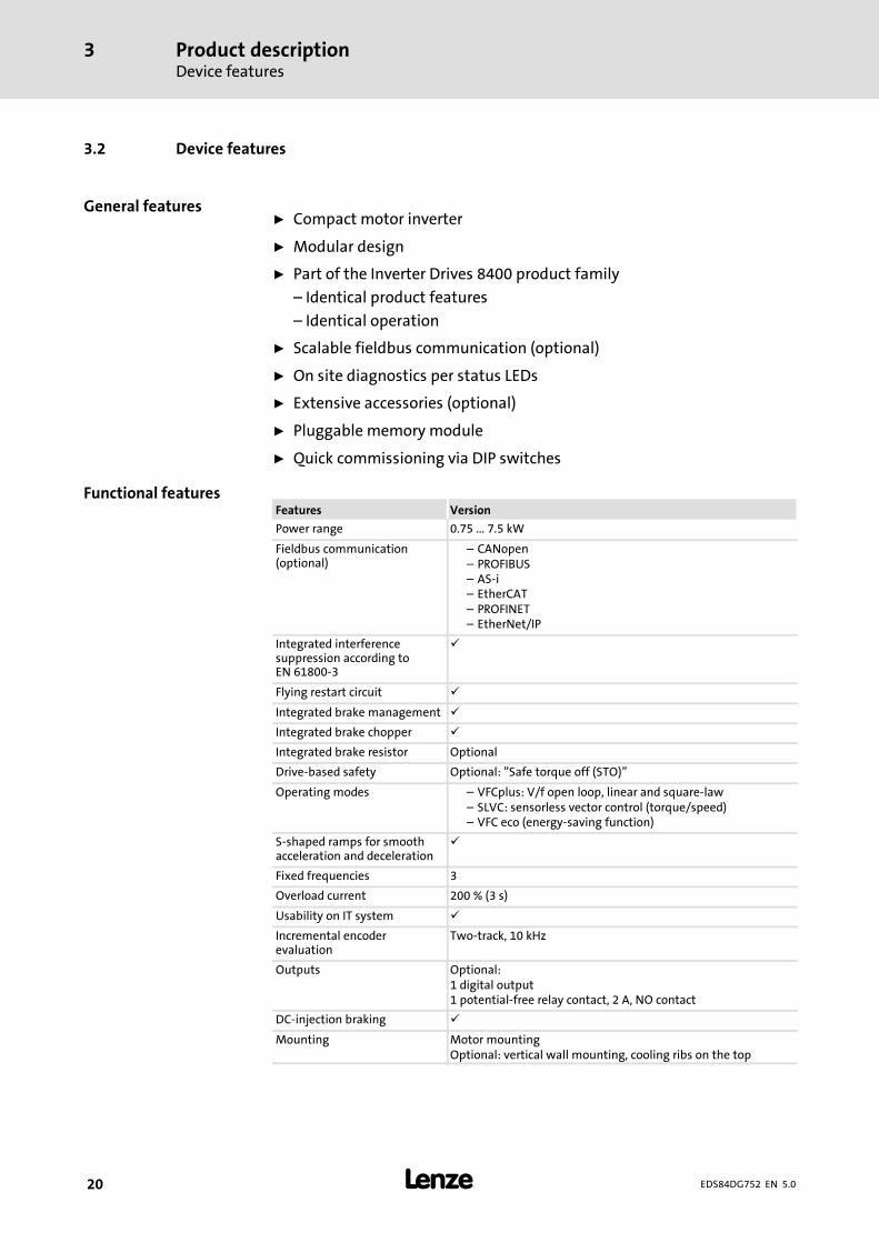
3.2 Device features
ƒ Compact motor inverter
ƒ Modular design
ƒ Part of the Inverter Drives 8400 product family
– Identical product features
– Identical operation
ƒ Scalable fieldbus communication (optional)
ƒ On site diagnostics per status LEDs
ƒ Extensive accessories (optional)
ƒ Pluggable memory module
ƒ Quick commissioning via DIP switches
Features Version
Power range 0.75 ... 7.5 kW
Fieldbus communication(optional)
– CANopen– PROFIBUS– AS-i– EtherCAT– PROFINET– EtherNet/IP
Integrated interferencesuppression according toEN 61800-3
Flying restart circuit
Integrated brake management
Integrated brake chopper
Integrated brake resistor Optional
Drive-based safety Optional: ”Safe torque off (STO)”
Operating modes – VFCplus: V/f open loop, linear and square-law– SLVC: sensorless vector control (torque/speed)– VFC eco (energy-saving function)
S-shaped ramps for smoothacceleration and deceleration
Fixed frequencies 3
Overload current 200 % (3 s)
Usability on IT system
Incremental encoderevaluation
Two-track, 10 kHz
Outputs Optional:1 digital output1 potential-free relay contact, 2 A, NO contact
DC-injection braking
Mounting Motor mountingOptional: vertical wall mounting, cooling ribs on the top
General features
Functional features

Product descriptionIdentification
3
21EDS84DG752 EN 5.0
3.3 Identification
Due to the modular design of the 8400 motec controllers, every unit has an ownnameplate.
The nameplate shows the type designation of the respective unit. The type designationserves to exactly identify a unit.
�180s
�
E84DGAK001
Type designation
Note
The type designation serves to identify detailed device properties with the following typecode. The listing of the type code, features, and device properties does not consider anylimitations of possible combinations.

Product descriptionType codeIntroducing information
3
22 EDS84DG752 EN 5.0
3.4 Type code
3.4.1 Introducing information
Due to themodular structure of the 8400 motec controller, every unit needs an own typekey. Though, a type key is also defined for the 8400 motec controller as a set, it cannot beattached visibly to the set or single units due to practical and logistical reasons.
The following lists inform you about the type keys for:
ƒ Wiring Unit
Wiring level to the motor and mains connection
ƒ Communication Unit
Connection level for fieldbus communication and further inputs and outputs, partiallyoptional
ƒ Drive unit
8400 motec controller
ƒ Accessories
Efficiency-improving and cost-reducing
3.4.2 The type codes
Wiring Unit
E84DGV N x E
Module partWiring Unit - 8400 motec
VersionN = not relevant
Size1 = 063 / 071 (E84DGDVB3714 ... 1124)2 = 080 / 090 / 100 (E84DGDVB5514 ... 1524)3 = 080 / 090 / 100 / 112 (E84DGDVB2224 ... 3024)4 = 080 / 090 / 100 / 112 (E84DGDVB4024 ... 7524)5 = 132 (E84DGDVB5524 ... 7524)
EnclosureE = IP66

Product descriptionType code
The type codes
3
23EDS84DG752 EN 5.0
Communication Unit
E84DGFC x x x x
Module partCommunication Unit - 8400 motec
Communication (fieldbus)N = NO BUS (without fieldbus)A = AS-iC = CANopenG = EtherNet/IPP = PROFIBUSR = PROFINETS = standard I/OT = EtherCAT
Connection system - communication and ION = NO BUS/standard IO: TerminalA = communication: M12, IO: Terminal9 = communication: M12, IO: M12
Drive-based safetyN = noneJ = safety option 10 (STO - safe torque off)
EnclosureP = IP65E= IP66
Drive Unit
E84DGDV B xxx 4 2 x S
Module partDrive Unit - 8400 motec
VersionB = not relevant
Power e.g.152 = 15 x 102 W = 1.5 kW
Voltage class4 = 400/480 V, 3/PE AC (also for IT systems)
Memory module2 = standard 8400 motec
EnclosureP = IP65E= IP66
Control elementS = standard (DIP switches/ potentiometer/X70)

Product descriptionType codeThe type codes
3
24 EDS84DG752 EN 5.0
8400 motec Set
E84DV B x xxx x S x x x 2 x x
Product rangeInverter Drives 8400 motec
VersionB = not relevant
DesignM =motor-mounted deviceW = wall-mounted device
Power e.g.152 = 15 x 102 W = 1.5 kW
Voltage class4 = 400/480 V, 3/PE AC (also for IT systems)
Control elementS = standard (DIP switches/ potentiometer/X70)
Communication (fieldbus)N = NO BUS (without fieldbus)A = AS-iC = CANopenG = EtherNet/IPP = PROFIBUSR = PROFINETS = standard I/OT = EtherCAT
Connection system - communication and ION = NO BUS/standard IO: TerminalA = communication: M12, IO: Terminal9 = communication: M12, IO: M12
Drive-based safetyN = noneJ = safety option 10 (safe torque off)
(incl. supplements IO)
Memory module2 = for motec
EnclosureP = IP65E= IP66
Size1 = 063 / 071 (E84DGDVB3714 ... 1124)2 = 080 / 090 / 100 (E84DGDVB5514 ... 1524)3 = 080 / 090 / 100 / 112 (E84DGDVB2224 ... 3024)4 = 080 / 090 / 100 / 112 (E84DGDVB4024 ... 7524)5 = 132 (E84DGDVB5524 ... 7524)

Product descriptionOverview of control terminals
3
25EDS84DG752 EN 5.0
3.5 Overview of control terminals
The control terminals of the 8400 motec controllers are available in the entire system intwo versions:
ƒ Extended or
ƒ Standard.
The control terminals are always located in the Communication Unit.
The type of fieldbus version, power class of the inverter or motor frame size have noinfluence on the availability.
Connection options for Communication Unit WU
Plugs X3 X61 X4 X1
Name Fieldbus Safety Digital input/output Analoginput
Relay Holdingbrake
Type SIA/SIB RFR DIx DO1 AI/AU COM/NO BD1/BD2
E84DGFCNNNxNO BUS(withoutfieldbus)
- 1 x 2 x - -
E84DGFCSNNxStandard I/O(withoutfieldbus)
- 1 x 5 x
E84DGFCAxNxASi
-
1 x 5 x
- -
E84DGFCAxJx
E84DGFCCxNxCAN
- - -
E84DGFCCxJx
E84DGFCGxNxEtherNet/IP
- - -
E84DGFCGxJx
E84DGFCPxNxPROFIBUS
- - -
E84DGFCPxJx
E84DGFCRxNxPROFINET
- - -
E84DGFCRxJx
E84DGFCTxNxEtherCAT
- - -
E84DGFCTxJx
available- not available

Technical dataGeneral data and operating conditions
4
26 EDS84DG752 EN 5.0
4 Technical data
4.1 General data and operating conditions
Conformity and approval
Conformity
CE 2006/95/EC LowVoltage Directive
EAC
(TR CU 004/2011)On safety of low voltageequipment
Eurasian ConformityTR CU: Technical Regulation ofCustoms Union
EAC
(TR CU 020/2011)Electromagneticcompatibility of technicalmeans
Eurasian ConformityTR CU: Technical Regulation ofCustoms Union
Approval
UR UL 508C Power ConversionEquipment, File No.E170350CUR C22.2 No 14

Technical dataGeneral data and operating conditions
4
27EDS84DG752 EN 5.0
Protection of persons and equipment
Enclosure EN 60529 IP65optional: IP66
in ready-for-use state: Close unused bores for cable
glands with blanking plugs! Close unused connectors with
protection covers or blankingplugs!
NEMA 250 Protection according to Type 4
(Earth) leakage current EN 61800-5-1 > 3.5 mA AC, > 10 mA DC Observe the regulations andsafety instructions!
Total fault current In TN systems the following earth-leakage circuit breakerscan be used:
Motor mounting E84DGDVB3714...
E84DGDVB152430 mA, type B
E84DGDVB2224...
E84DGDVB7524300 mA, type B
Wall mounting E84DGDVB3714...
E84DGDVB7524300 mA, type B
Additional equipotentialbonding
M5 thread with terminal in theWU for connection of a16mm@ PE cable
Protective insulation ofcontrol circuits
EN 61800-5-1 Safe isolation frommains by double (reinforced) insulation
Insulation resistance EN 61800-5-1 Site altitude
0 ... 2000 m Overvoltage category III
2000 ... 4000 m Overvoltage category II
Short-circuit strength EN 61800-5-1 Connection:
Motor To a limited extent, thecontroller is inhibited, erroracknowledgement required
Motor holding brake, brakeresistor No
PTC, control terminals Full
Earth-fault strength EN 61800-5-1 Connection:
Motor (at controllerenable)
To a limited extent, thecontroller is inhibited, erroracknowledgement required
Motor (during operation) No
Brake resistor, PTC No
Protective measuresagainst
Short circuit on the motor side at switch-on and duringoperation
Motor stalling Motor overtemperature
– Input for PTC or thermal contact– I2t monitoring
Cyclic mains switching Switchings/minute 3
Switchings/hour Max. 20
Switching pause After switching the mains 3times in one minute, there mustbe a switching pause of9 minutes.
Starting current 2 x IN

Technical dataGeneral data and operating conditions
4
28 EDS84DG752 EN 5.0
Supply conditions
Mains connection
Power system
TT, TN(with an earthedneutral)
Operation permitted without restrictions.
IT Implement the measure described for IT systems (remove ITscrew).The machine/systemmanufacturer is responsible forcompliance with EMC requirements for noise emission(EN 61800-3) for the machine/plant!Operation with an integrated safety system isnot permissible.
Motor connection
Motors EN 60034 Only use motors suitable for inverter operation. Insulationresistance:at least û 1.5 kV, at least du/dt 5 kV/s
Length of the motorcable
< 20 m (Lenze system cable, shielded)
Ambient conditions
Climatic
Storage IEC/EN 60721-3-1 1K3 (-30 ... +60 °C)
Transport IEC/EN 60721-3-2 2K3 (-30 ... +75 °C)
Operation IEC/EN 60721-3-3 3K3 (-30 ... +55 °C)Operation at 4 kHz: > +45 °C: Reduce the rated output currentby 2.5 %/°C.Operation at 8/16 kHz: > +40 °C: Reduce the rated outputcurrent by 2.5 %/°C.
Site altitude < 4000 m amslAbove 1000 m amsl reduce the rated output current by5 %/ 1000 m.
Pollution IEC/EN 61800-5-1 Degree of pollution 2
Mechanical
Vibration resistance (9.81 m/s2 = 1 g)
Motor mounting Germanischer Lloyd General conditions: Acceleration resistant up to 2 g
IEC/EN 60721-3-3 3M6
Wall mounting withE84DZMAWE1
Germanischer Lloyd General conditions: Acceleration resistant up to 2 g
IEC/EN 60721-3-3 3M6
Mounting conditions
Mounting place
Motor mounting Standard
Wall mounting With optional wall adapter Ensure convection cooling in theniches!
Mounting position
Wall mounting
E84DGDVB3714...
E84DGDVB3024
Vertical, cooling rips at thetop
Arrangement of several devicesonly to the sides, so that theconvection cooling remainsensured!
E84DGDVB4024...
E84DGDVB7524
Optional

Technical dataGeneral data and operating conditions
4
29EDS84DG752 EN 5.0
EMC
Noise emission (in TN and TT mains)
Cable-guided EN 61800-3
Motor mounting E84DVBM3714 ... 1524 Category C1
E84DVBM2224 ... 3024for switching frequency 4 kHz
Category C1
E84DVBM4024 ... 7524 Category C2
Wall mounting EN 61800-3 E84DVBW3714 ... 7524for switching frequency 4 kHz andwith Lenze system cable 20 m
Category C2
E84DVBW3714 ... 7524 forswitching frequency 8 kHz andwith Lenze system cable 10 m
Category C2
Radiation EN 61800-3 E84DVBM3714 ... 1524for switching frequency 8 kHz
Category C1
E84DVBM2224 ... 7524for switching frequency 8 kHz
Category C2
Noise immunity (according to requirements of EN 61800-3)
Electrostatic discharge(ESD)
EN 61000-4-2 8 kV with air discharge,4 kV with contact discharge against housing
Radio frequency
Conducted EN 61000-4-6 150 kHz ... 80 MHz, 10 V/m 80 % AM (1kHz)
Interference(housing)
EN 61000-4-3 80 MHz ... 1000 MHz, 10 V/m 80 % AM (1kHz)
Burst
Power terminals andinterfaces
EN 61000-4-4 2 kV/5 kHz
Signal interfaces EN 61000-4-4 1 kV/5 kHz
Control terminals EN 61000-4-4 2 kV/5 kHz
Surge
Power terminals EN 61000-4-5 1.2/50 s,1 kV phase/phase, 2 kV phase/PE
Control terminals EN 61000-4-5 1.2/50 s, 1 kV
Operation on publicsupply systems
EN 61000-3-2EN 61000-3-12
The devices are intended for use in an industrialenvironment. When being used on public network, additionalmeasures must be taken to limit the expected radiointerference. The compliance with the requirements for themachine/plant is the responsibility of the manufacturer ofthe machine or system!
Voltage deviations
Voltage dips EN 61800-3 Short mains voltage dips (comp. IEC 61000-2-1) can lead to aswitch-off of the motor.

Technical dataGeneral data and operating conditions
4
30 EDS84DG752 EN 5.0
Control
Control modes
VFCplus: V/f control (linear or square-law)SLVC: Sensorless vector control (speed)VFCplus eco: Energy-efficient V/f control
Switching frequency
4 kHz, 8 kHz, 16 kHz,
Torque behaviour
Maximum torque 1.5 x Mrated for 60 s2.0 x Mrated for 3 s
if rated motor power = rated controller power
Setting range 1 : 10 SLVC: In speed range 3 ... 50 HzV/f: In speed range 10 ... 50 Hz
Sensorless vector control (speed)
Minimum outputfrequency
0.5 Hz (0 ... Mrated)
Accuracy 0.5 %In the speed range 3 ... 50 Hz
Smooth running 0.1 Hz
Output frequency
Range -300 Hz ... +300 Hz
Absolute resolution 0.2 Hz
Standardisedresolution
Parameter data: 0.01 %, process data: 0.006 % (= 214)
Digital setpoint selection
Accuracy 0.01 %
Analog setpoint selection
Accuracy 2 % Relating to final value

Technical dataRated dataOverview
4
31EDS84DG752 EN 5.0
4.2 Rated data
4.2.1 Overview
Input data
Basis of the data
Mains Voltage Voltage range Frequency range
ULrated [V] ULrated [V] f [Hz]
3/PE AC 400 320 - 0 % ... 440 + 0 % 45 - 0 % ... 65 + 0 %
3/PE AC 480 432 - 0 % ... 528 + 0 % 45 - 0 % ... 65 + 0 %
Voltage Frequency Rated current [A] Number ofphases
[V] [Hz] up to +45 °C up to +55 °C
E84DGDVB3714 400/480 50/60 1.3/1.1 1.0/0.8 3
E84DGDVB5514 400/480 50/60 1.8/1.5 1.4/1.1 3
E84DGDVB7514 400/480 50/60 2.4/2.0 1.8/1.5 3
E84DGDVB1124 400/480 50/60 3.2/2.7 2.4/2.0 3
E84DGDVB1524 400/480 50/60 3.8/3.1 2.9/2.3 3
E84DGDVB2224 400/480 50/60 5.6/4.6 4.2/3.5 3
E84DGDVB3024 400/480 50/60 7.2/5.9 5.4/4.4 3
E84DGDVB4024 400/480 50/60 9.3/7.7 7.0/5.8 3
E84DGDVB5524 400/480 50/60 12.8/10.6 9.6/8.0 3
E84DGDVB7524 400/480 50/60 16.3/13.5 12.3/10.1 3
Ambient temperature, switching frequency 4 kHz
Output data
Voltage Frequency Rated current [A] Number ofphases
[V] [Hz] up to +45 °C up to +55 °C
E84DGDVB3714 0 ... 400/480 0 ... 300 1.3/1.1 1.0/0.8 3
E84DGDVB5514 0 ... 400/480 0 ... 300 1.8/1.5 1.4/1.1 3
E84DGDVB7514 0 ... 400/480 0 ... 300 2.4/2.0 1.8/1.5 3
E84DGDVB1124 0 ... 400/480 0 ... 300 3.2/2.7 2.4/2.0 3
E84DGDVB1524 0 ... 400/480 0 ... 300 3.9/3.2 2.9/2.4 3
E84DGDVB2224 0 ... 400/480 0 ... 300 5.6/4.7 4.2/3.5 3
E84DGDVB3024 0 ... 400/480 0 ... 300 7.3/6.0 5.4/4.5 3
E84DGDVB4024 0 ... 400/480 0 ... 300 9.5/7.9 7.1/5.9 3
E84DGDVB5524 0 ... 400/480 0 ... 300 13.0/10.8 9.8/8.1 3
E84DGDVB7524 0 ... 400/480 0 ... 300 16.5/13.7 12.4/10.3 3
Ambient temperature, switching frequency 4 kHz
Note!The maximally possible output voltage is approx. 94 % of the mains voltage.
Technical dataRated dataOverview
4
32 EDS84DG752 EN 5.0
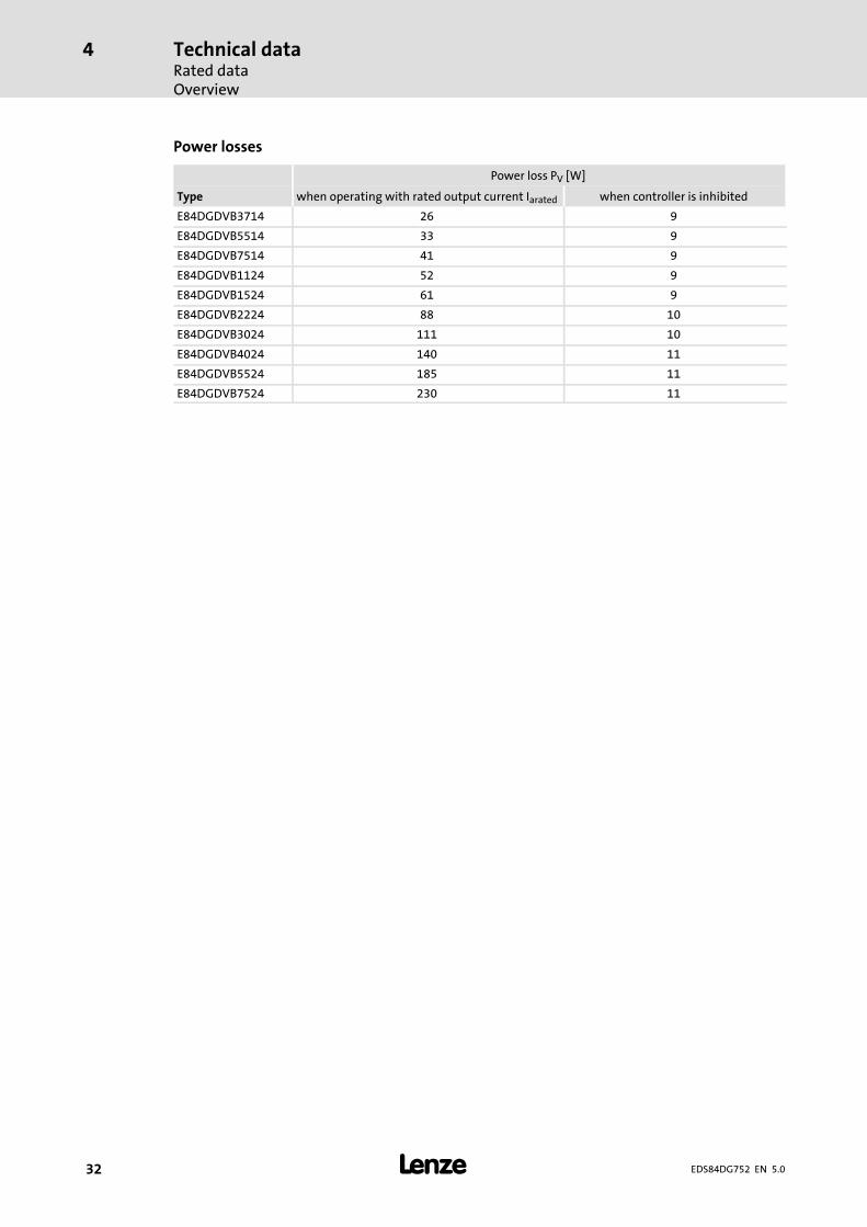
Power losses
Power loss PV [W]
Type when operating with rated output current Iarated when controller is inhibited
E84DGDVB3714 26 9
E84DGDVB5514 33 9
E84DGDVB7514 41 9
E84DGDVB1124 52 9
E84DGDVB1524 61 9
E84DGDVB2224 88 10
E84DGDVB3024 111 10
E84DGDVB4024 140 11
E84DGDVB5524 185 11
E84DGDVB7524 230 11

Technical dataRated data
Operation at rated mains voltage 400 V
4
33EDS84DG752 EN 5.0
4.2.2 Operation at rated mains voltage 400 V
Basis of the data
Mains Voltage Voltage range Frequency range
ULrated [V] ULrated [V] f [Hz]
3/PE AC 400 320 - 0 % ... 440 + 0 % 45 - 0 % ... 65 + 0 %
Mains current Output power Motor power
at Iarated U, V, W 4 pol. ASM
Type ILrated [A] Sarated [kVA] Parated [kW]
E84DGDVB3714 1.3 0.8 0.37
E84DGDVB5514 1.8 1.1 0.55
E84DGDVB7514 2.4 1.5 0.75
E84DGDVB1124 3.2 2.0 1.1
E84DGDVB1524 3.8 2.4 1.5
E84DGDVB2224 5.6 3.4 2.2
E84DGDVB3024 7.2 4.4 3.0
E84DGDVB4024 9.3 5.7 4.0
E84DGDVB5524 12.8 7.8 5.5
E84DGDVB7524 16.3 9.9 7.5
Output currents [A] at switching frequency
2 kHz 4 kHz 8 kHz 16 kHz
Type Iarated2 IaM2 Iarated4 IaM4 Iarated8 IaM8 Iarated16 IaM16
E84DGDVB3714 - - 1.3 2.6 1.3 2.6 0.9 1.6
E84DGDVB5514 - - 1.8 3.6 1.8 3.6 1.2 2.2
E84DGDVB7514 - - 2.4 4.8 2.4 4.8 1.6 2.9
E84DGDVB1124 - - 3.2 6.4 3.2 6.4 2.1 3.8
E84DGDVB1524 - - 3.9 7.8 3.9 7.8 2.6 4.7
E84DGDVB2224 - - 5.6 11.2 5.6 11.2 3.7 6.7
E84DGDVB3024 - - 7.3 14.6 7.3 14.6 4.9 8.8
E84DGDVB4024 - - 9.5 19.0 9.5 19.0 6.3 11.4
E84DGDVB5524 - - 13.0 26.0 13.0 26.0 8.7 15.6
E84DGDVB7524 - - 16.5 33.0 16.5 33.0 11.0 19.8
IaNx Rated value of continuous output currentIaMx Maximum output current (overload current)
Periodic load change of 3 s with IaMx and recovery time of 12 s according tothe tables under chapter 4.4
Can be obtained in the setting ”x kHz fixed/...” in C00018Switchingfrequency
If the maximum heatsink temperature is reached, the switching frequency isreduced to 4 kHz.In the setting ”x kHz var./...” in C00018 the switching frequency is reduceddepending on the output current.Depending on the switching frequency and e.g. the ambient temperature, itmay be required to reduce the output current (chapter 4.1, operatingconditions).

Technical dataRated dataOperation at rated mains voltage 400 V
4
34 EDS84DG752 EN 5.0
Fuses and cable cross-sections
ƒ Point-to-point connection - direct wiring of the mains voltage - typical fusing
Operation
Type Installation according to EN 60204-1 1) Installation accordingto UL 2)
FI 3)
L1, L2, L3 - laying system L1, L2, L3
B2 C F
[A] [A] [mm2] [mm2] [mm2] [A] [AWG] [mA]
E84DGDVB3714 C 16 16 2.5 - - 15 12 30
E84DGDVB5514 C 16 16 2.5 - - 15 12 30
E84DGDVB7514 C 16 16 2.5 - - 15 12 30
E84DGDVB1124 C 16 16 2.5 - - 15 12 30
E84DGDVB1524 C 16 16 2.5 - - 15 12 30
E84DGDVB2224 C 16 16 2.5 - - 15 12 300
E84DGDVB3024 C 16 16 2.5 - - 15 12 300
E84DGDVB4024 C20 20 4.0 - - 20 12 300
E84DGDVB5524 C20 20 4.0 - - 20 12 300
E84DGDVB7524 C 20 20 4.0 - - 20 12 300
ƒ Multiple connection - loop-through connection of the mains voltage - maximumfusing
Operation
Type Installation according to EN 60204-1 1) Installation accordingto UL 2)
FI 3)
L1, L2, L3 - laying system L1, L2, L3
B2 C F
[A] [A] [mm2] [mm2] [mm2] [A] [AWG] [mA]
E84DGDVB3714 C 32 32 6.0 - - 15 12 30
E84DGDVB5514 C 32 32 6.0 - - 15 12 30
E84DGDVB7514 C 32 32 6.0 - - 15 12 30
E84DGDVB1124 C 32 32 6.0 - - 15 12 30
E84DGDVB1524 C 32 32 6.0 - - 15 12 30
E84DGDVB2224 C 32 32 6.0 - - 25 10 300
E84DGDVB3024 C 32 32 6.0 - - 25 10 300
E84DGDVB4024 C 50 50 16.0 - - 50 6 300
E84DGDVB5524 C 50 50 16.0 - - 50 6 300
E84DGDVB7524 C 50 50 16.0 - - 50 6 300
1) These values are recommendations only. Other dimensioning values/laying systems are possible (e.g. according toVDE 0298-4). The cable cross-sections apply under the following conditions: Use of PVC-insulated copper cables,conductor temperature < 70 °C, ambient temperature < 45°C, no bundling of cables or cores, three loaded cores.
2) Only use UL-approved cables, fuses and fuse holders.UL fuse: voltage 500 V, tripping characteristic e.g. ”CC”. The cable cross-sections apply under the followingconditions: conductor temperature < 75 °C, ambient temperature < 45°C.
3) Universal-current sensitive earth-leakage circuit breaker, short-time delayed Circuit breaker Fuse of gG/gL utilisation category or semiconductor fuses of gRL utilisation category FuseObserve national and regional regulations

Technical dataRated data
Operation at increased rated power at 400 Vmains voltage
4
35EDS84DG752 EN 5.0
4.2.3 Operation at increased rated power at 400 V mains voltage
In continuous operation, the controllers can be actuatedwith amore powerfulmotor. Theoverload capacity is limited to120 %. Typical applications arepumpswithaquadratic loadcharacteristic, or fans.
Note!Operation with an increased rated power is only permitted ...ƒ with the rated data specified for the controller.ƒ within the mains voltage range specified.ƒ with the switching frequency 4 kHz.ƒ at a max. ambient temperature of 40 °Cƒ with the fuses and cable cross-sections specified for this operation.ƒ after parameterisation according to the specifications (cf. EDS84DM...software manual)
Basis of the data
Mains Voltage Voltage range Frequency range
ULrated [V] ULrated [V] f [Hz]
3/PE AC 400 320 - 0 % ... 440 + 0 % 45 - 0 % ... 65 + 0 %
Mains current Output power Motor power
at Iarated U, V, W 4 pol. ASM
Type ILrated [A] Sarated [kVA] Parated [kW]
E84DGDVB3714 1.6 1.0 0.55
E84DGDVB5514 2.2 1.3 0.75
E84DGDVB7514 2.9 1.8 1.1
E84DGDVB1124 3.8 2.4 1.5
E84DGDVB1524 1) 4.5 3.0 1.8
E84DGDVB2224 6.7 4.1 2.2
E84DGDVB3024 1) 8.6 5.3 4.0
E84DGDVB4024 11.1 6.8 5.5
E84DGDVB5524 15.3 9.4 7.5
E84DGDVB7524 19.5 11.9 9.2
1) Operation with an increased rated power only for motor mounting.

Technical dataRated dataOperation at increased rated power at 400 Vmains voltage
4
36 EDS84DG752 EN 5.0
Switching frequency-dependent output currents
Output currents [A] at switching frequency
2 kHz 4 kHz 8 kHz 16 kHz
Type Iarated2 IaM2 Iarated4 IaM4 Iarated8 IaM8 Iarated16 IaM16
E84DGDVB3714 - - 1.6 2.6 - - - -
E84DGDVB5514 - - 2.2 3.6 - - - -
E84DGDVB7514 - - 2.9 4.8 - - - -
E84DGDVB1124 - - 3.8 6.4 - - - -
E84DGDVB1524 1) - - 4.7 7.8 - - - -
E84DGDVB2224 - - 6.7 11.2 - - - -
E84DGDVB3024 1) - - 8.7 14.6 - - - -
E84DGDVB4024 - - 11.4 19.0 - - - -
E84DGDVB5524 - - 15.6 26.0 - - - -
E84DGDVB7524 - - 19.8 33.0 - - - -
IaNx Rated value of continuous output currentIaMx Maximum output current (overload current)
Periodic load change of 3 s with IaMx and recovery time of 12 s according tothe tables under chapter 4.4
1) Operation with an increased rated power only for motor mounting.
Fuses and cable cross-sections
The data/recommendations for operation on a ratedmains voltage 400 V can be applied.
( 34)

Technical dataRated data
Operation with rated mains voltage 480 V
4
37EDS84DG752 EN 5.0
4.2.4 Operation with rated mains voltage 480 V
Basis of the data
Mains Voltage Voltage range Frequency range
ULrated [V] ULrated [V] f [Hz]
3/PE AC 480 432 - 0 % ... 528 + 0 % 45 - 0 % ... 65 + 0 %
Mains current Output power Motor power
at Iarated U, V, W 4 pol. ASM
Type ILrated [A] Sarated [kVA] Parated [kW]
E84DGDVB3714 1.1 0.8 0.37
E84DGDVB5514 1.5 1.1 0.55
E84DGDVB7514 2.0 1.5 0.75
E84DGDVB1124 2.7 2.1 1.1
E84DGDVB1524 3.1 2.4 1.5
E84DGDVB2224 4.6 3.5 2.2
E84DGDVB3024 5.9 4.5 3.0
E84DGDVB4024 7.7 5.7 4.0
E84DGDVB5524 10.6 7.9 5.5
E84DGDVB7524 13.5 10.0 7.5
Output currents [A] at switching frequency
2 kHz 4 kHz 8 kHz 16 kHz
Type Iarated2 IaM2 Iarated4 IaM4 Iarated8 IaM8 Iarated16 IaM16
E84DGDVB3714 - - 1.1 2.2 1.1 2.2 0.7 1.3
E84DGDVB5514 - - 1.5 3.0 1.5 3.0 1.0 1.8
E84DGDVB7514 - - 2.0 4.0 2.0 4.0 1.3 2.4
E84DGDVB1124 - - 2.7 5.4 2.7 5.4 1.8 3.2
E84DGDVB1524 - - 3.2 6.4 3.2 6.4 2.1 3.8
E84DGDVB2224 - - 4.7 9.4 4.7 9.4 3.1 5.6
E84DGDVB3024 - - 6.0 12.0 6.0 12.0 4.0 7.2
E84DGDVB4024 - - 7.9 15.8 7.9 15.8 5.3 9.5
E84DGDVB5524 - - 10.8 21.6 10.8 21.6 7.2 13.0
E84DGDVB7524 - - 13.7 27.4 13.7 27.4 9.1 16.4
IaNx Rated value of continuous output currentIaMx Maximum output current (overload current)
Periodic load change of 3 s with IaMx and recovery time of 12 s according tothe tables under chapter 4.4
Can be obtained in the setting ”x kHz fixed/...” in C00018Switchingfrequency
If the maximum heatsink temperature is reached, the switching frequency isreduced to 4 kHz.In the setting ”x kHz var./...” in C00018 the switching frequency is reduceddepending on the output current.Depending on the switching frequency and e.g. the ambient temperature, itmay be required to reduce the output current (chapter 4.1, operatingconditions).

Technical dataRated dataOperation with rated mains voltage 480 V
4
38 EDS84DG752 EN 5.0
Fuses and cable cross-sections
ƒ Point-to-point connection - direct wiring of the mains voltage - typical fusing
Operation
Type Installation according to EN 60204-1 1) Installation accordingto UL 2)
FI 3)
L1, L2, L3 - laying system L1, L2, L3
B2 C F
[A] [A] [mm2] [mm2] [mm2] [A] [AWG] [mA]
E84DGDVB3714 C 16 16 2.5 - - 15 12 30
E84DGDVB5514 C 16 16 2.5 - - 15 12 30
E84DGDVB7514 C 16 16 2.5 - - 15 12 30
E84DGDVB1124 C 16 16 2.5 - - 15 12 30
E84DGDVB1524 C 16 16 2.5 - - 15 12 30
E84DGDVB2224 C 16 16 2.5 - - 15 12 300
E84DGDVB3024 C 16 16 2.5 - - 15 12 300
E84DGDVB4024 C20 20 4.0 - - 20 12 300
E84DGDVB5524 C20 20 4.0 - - 20 12 300
E84DGDVB7524 C 20 20 4.0 - - 20 12 300
ƒ Multiple connection - loop-through connection of the mains voltage - maximumfusing
Operation
Type Installation according to EN 60204-1 1) Installation accordingto UL 2)
FI 3)
L1, L2, L3 - laying system L1, L2, L3
B2 C F
[A] [A] [mm2] [mm2] [mm2] [A] [AWG] [mA]
E84DGDVB3714 C 32 32 6.0 - - 15 12 30
E84DGDVB5514 C 32 32 6.0 - - 15 12 30
E84DGDVB7514 C 32 32 6.0 - - 15 12 30
E84DGDVB1124 C 32 32 6.0 - - 15 12 30
E84DGDVB1524 C 32 32 6.0 - - 15 12 30
E84DGDVB2224 C 32 32 6.0 - - 25 10 300
E84DGDVB3024 C 32 32 6.0 - - 25 10 300
E84DGDVB4024 C 50 50 16.0 - - 50 6 300
E84DGDVB5524 C 50 50 16.0 - - 50 6 300
E84DGDVB7524 C 50 50 16.0 - - 50 6 300
1) These values are recommendations only. Other dimensioning values/laying systems are possible (e.g. according toVDE 0298-4). The cable cross-sections apply under the following conditions: Use of PVC-insulated copper cables,conductor temperature < 70 °C, ambient temperature < 45°C, no bundling of cables or cores, three loaded cores.
2) Only use UL-approved cables, fuses and fuse holders.UL fuse: voltage 500 V, tripping characteristic e.g. ”CC”. The cable cross-sections apply under the followingconditions: conductor temperature < 75 °C, ambient temperature < 45°C.
3) Universal-current sensitive earth-leakage circuit breaker, short-time delayed Circuit breaker Fuse of gG/gL utilisation category or semiconductor fuses of gRL utilisation category FuseObserve national and regional regulations

Technical dataSwitching frequency reduction
4
39EDS84DG752 EN 5.0
4.3 Switching frequency reduction
Under certainoperating conditions, themaximumoutput current is limited for all devices:
ƒ When the maximum heatsink temperature is exceeded, the controller switchesfrom 16 kHz to 8 kHz and from 8 kHz to 4 kHz, irrespective of the switchingfrequency mode. This function can be deactivated via C00144.
If the heatsink temperature increases above 105 °C, the controller is inhibited and theerror message ”OH1: Heatsink overtemperature” is output.
The error response is also triggered when the switching frequency reduction isdeactivated.
Technical dataOvercurrent operation
4
40 EDS84DG752 EN 5.0
4.4 Overcurrent operation
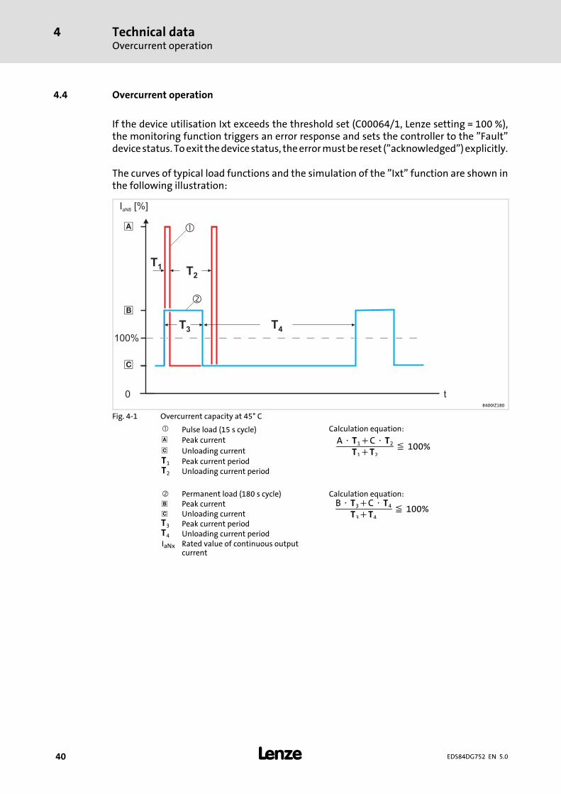
If the device utilisation Ixt exceeds the threshold set (C00064/1, Lenze setting = 100 %),the monitoring function triggers an error response and sets the controller to the ”Fault”devicestatus. Toexit thedevicestatus, theerrormustbe reset (”acknowledged”)explicitly.
The curves of typical load functions and the simulation of the ”Ixt” function are shown inthe following illustration:
t0
100%
�
�
�
I [%]aN8
T2
T3
T4
T1
�
�
8400IZ180
Fig. 4-1 Overcurrent capacity at 45° C
Pulse load (15 s cycle) Calculation equation: Peak current A ⋅ T1+C ⋅ T2
T1+T2≦ 100% Unloading current
T1 Peak current periodT2 Unloading current period
Permanent load (180 s cycle) Calculation equation: Peak current B ⋅ T3+C ⋅ T4
T3+T4≦ 100% Unloading current
T3 Peak current periodT4 Unloading current periodIaNx Rated value of continuous output
current

Technical dataOvercurrent operation
4
41EDS84DG752 EN 5.0
Type
Iamax/IaN8 [%] in 15-s cycle
f = 2 kHz f = 4 kHz f = 8 kHz f = 16 kHz
E84DGDVB3714
- - 200 75 200 75 120 50
E84DGDVB5514
E84DGDVB7514
E84DGDVB1124
E84DGDVB1524
E84DGDVB2224
E84DGDVB3024
E84DGDVB4024
E84DGDVB5524
E84DGDVB7524
Type
Iamax/IaN8 [%] in 180-s cycle
f = 2 kHz f = 4 kHz f = 8 kHz f = 16 kHz
E84DGDVB3714
- - 150 75 150 75 100 50
E84DGDVB5514
E84DGDVB7514
E84DGDVB1124
E84DGDVB1524
E84DGDVB2224
E84DGDVB3024
E84DGDVB4024
E84DGDVB5524
E84DGDVB7524
Tip!For calculations of application-specific cycles please contact your Lenze contactperson.

Technical dataTerminal descriptionOverview
4
42 EDS84DG752 EN 5.0
4.5 Terminal description
4.5.1 Overview
0.37 ... 3 kW
E84DGDV001
WU -Wiring Unit
X1/L1, L2, L3 MainsX1/U, V, W MotorX1/Rb1, Rb2 Brake resistorX1/BD1, BD2 Motor holding brakeX1/T1, T2 Motor temperature monitoring Protective earth
CU - Communication Unit
The connection opportunities depend on the communication module option.
X4/COM, NO Switching contact, potential-freeX4/Ax, GND Analog inputX4/RFR, DIx, DO1 Digital inputs and outputsX4/24O,GND 24-V supply voltage for external sensorsX3/X31/X32 FieldbusX61/... SafetyAx Position of LED display, connector or cable gland
DU - Drive Unit
X70 Diagnostics
Technical dataTerminal description
Overview
4
43EDS84DG752 EN 5.0
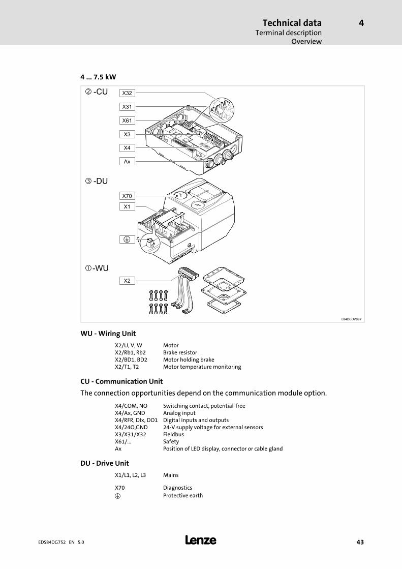
4 ... 7.5 kW
E84DGDV087
WU -Wiring Unit
X2/U, V, W MotorX2/Rb1, Rb2 Brake resistorX2/BD1, BD2 Motor holding brakeX2/T1, T2 Motor temperature monitoring
CU - Communication Unit
The connection opportunities depend on the communication module option.
X4/COM, NO Switching contact, potential-freeX4/Ax, GND Analog inputX4/RFR, DIx, DO1 Digital inputs and outputsX4/24O,GND 24-V supply voltage for external sensorsX3/X31/X32 FieldbusX61/... SafetyAx Position of LED display, connector or cable gland
DU - Drive Unit
X1/L1, L2, L3 Mains
X70 Diagnostics Protective earth

Technical dataPower terminals
4
44 EDS84DG752 EN 5.0
4.6 Power terminals
0.37 ... 3 kW - X1
E84DG032
Terminal data
Conductor cross-section Tightening torque [mm2] [AWG] [Nm] [lb-in]
X1E84DGDVB3714
...E84DGDVB1524
1 ... 4
18 ... 10 0.5 4.4 3.5 x 0.62 x 0.5 ... 2 x 2.51)
X1E84DGDVB2224
...E84DGDVB3024
1 ... 6
18 ... 8 0.8 7.0 3.5 x 0.62 x 0.5 ... 2 x 2.51)
1) For looping-through connections (daisy chain) => two conductors with TWIN wire end ferrule
4 ... 7.5 kW - X1 4 ... 7.5 kW - X2
E84DG086 a E84DG086 b
Terminal data
Conductor cross-section Tightening torque [mm2] [AWG] [Nm] [lb-in]
X1 1 ... 1618 ... 6 1.4 12 PZ 2
5.5 x 1.02 x 1 ... 2 x 6 1)
X2 1 ... 6 18 ... 8 0.8 7 PH 13.5 x 0.6
1) For looping-through connections (daisy chain) => two conductors with TWIN wire end ferrule
Technical dataPower terminals
Mains connection
4
45EDS84DG752 EN 5.0
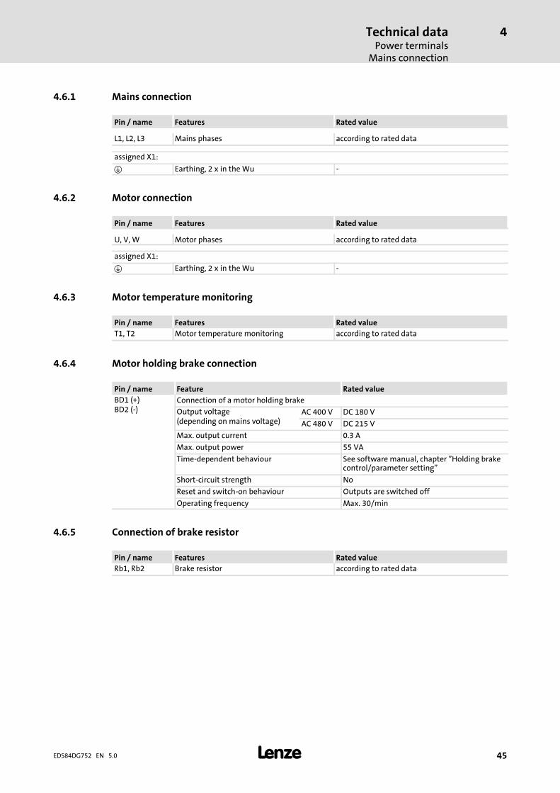
4.6.1 Mains connection
Pin / name Features Rated value
L1, L2, L3 Mains phases according to rated data
assigned X1:
Earthing, 2 x in theWu -
4.6.2 Motor connection
Pin / name Features Rated value
U, V, W Motor phases according to rated data
assigned X1:
Earthing, 2 x in theWu -
4.6.3 Motor temperature monitoring
Pin / name Features Rated valueT1, T2 Motor temperature monitoring according to rated data
4.6.4 Motor holding brake connection
Pin / name Feature Rated valueBD1 (+)BD2 (-)
Connection of a motor holding brake
Output voltage(depending on mains voltage)
AC 400 V DC 180 V
AC 480 V DC 215 V
Max. output current 0.3 A
Max. output power 55 VA
Time-dependent behaviour See software manual, chapter ”Holding brakecontrol/parameter setting”
Short-circuit strength No
Reset and switch-on behaviour Outputs are switched off
Operating frequency Max. 30/min
4.6.5 Connection of brake resistor
Pin / name Features Rated valueRb1, Rb2 Brake resistor according to rated data
Technical dataControl terminals
4
46 EDS84DG752 EN 5.0
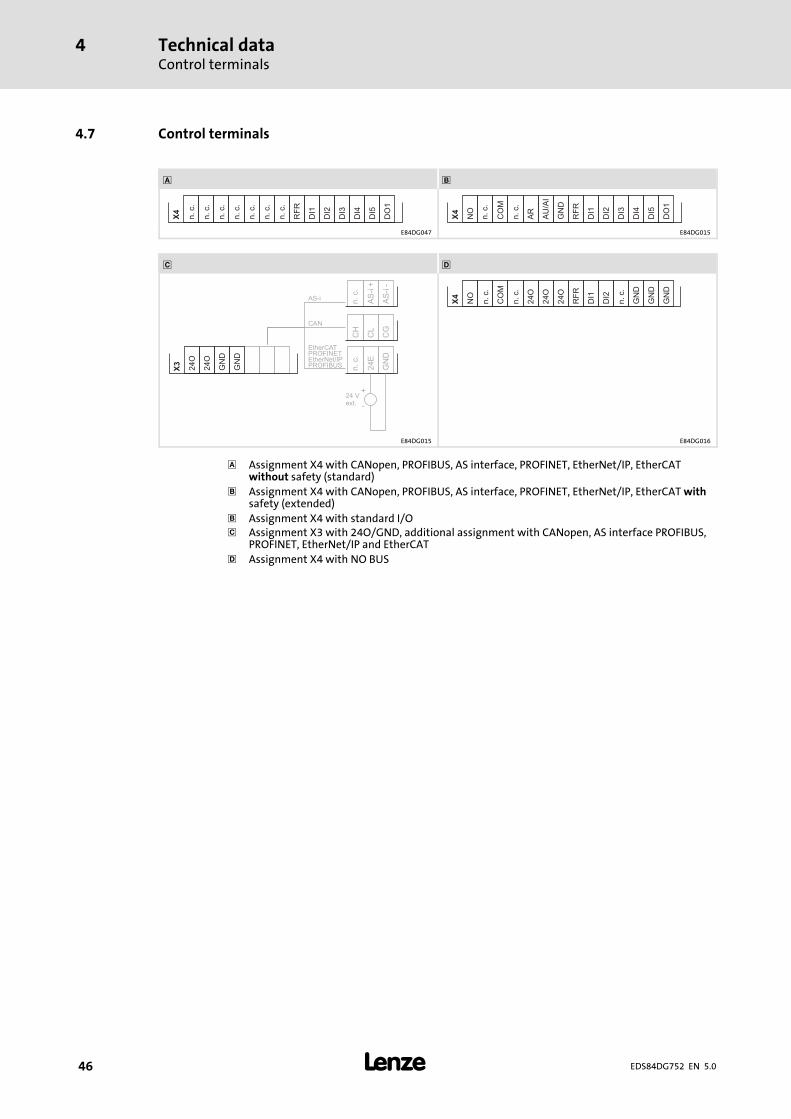
4.7 Control terminals
DI1
DI2
DI3
DI4
DI5
DO
1
RF
R
X4
n.c.
n.c.
n.c.
n.c.
n.c.
n.c.
n.c.
DI1
DI2
DI3
DI4
DI5
DO
1
RF
R
X4
GN
D
AU
/AI
AR
CO
M
NO
n.c.
n.c.
E84DG047 E84DG015
24O
24O
GN
D
GN
D
X3
AS-i AS
-i+
AS
-i-
n.c.
CH
CL
CG
CAN
24 Vext.
24E
GN
D
PROFIBUS
PROFINETEtherCAT
n.c.
+
-
EtherNet/IP
DI1
DI2
GN
D
GN
D
GN
D
RF
R
X4
CO
M
NO
n.c.
n.c.
n.c.
24O
24O
24O
E84DG015 E84DG016
Assignment X4 with CANopen, PROFIBUS, AS interface, PROFINET, EtherNet/IP, EtherCATwithout safety (standard)
Assignment X4 with CANopen, PROFIBUS, AS interface, PROFINET, EtherNet/IP, EtherCATwithsafety (extended)
Assignment X4 with standard I/O Assignment X3 with 24O/GND, additional assignment with CANopen, AS interface PROFIBUS,
PROFINET, EtherNet/IP and EtherCAT Assignment X4 with NO BUS

Technical dataControl terminals
4
47EDS84DG752 EN 5.0
Connection options for Communication Unit WU
Plugs X3 X61 X4 X1
Name Fieldbus Safety Digital input/output Analoginput
Relay Holdingbrake
Type SIA/SIB RFR DIx DO1 AI/AU COM/NO BD1/BD2
E84DGFCNNNxNO BUS(withoutfieldbus)
- 1 x 2 x - -
E84DGFCSNNxStandard I/O(withoutfieldbus)
- 1 x 5 x
E84DGFCAxNxASi
-
1 x 5 x
- -
E84DGFCAxJx
E84DGFCCxNxCAN
- - -
E84DGFCCxJx
E84DGFCGxNxEtherNet/IP
- - -
E84DGFCGxJx
E84DGFCPxNxPROFIBUS
- - -
E84DGFCPxJx
E84DGFCRxNxPROFINET
- - -
E84DGFCRxJx
E84DGFCTxNxEtherCAT
- - -
E84DGFCTxJx
available- not available

Technical dataControl terminalsDigital inputs
4
48 EDS84DG752 EN 5.0
4.7.1 Digital inputs
X4
Pin / name Features Rated value
RFRDI1DI2DI3DI4DI5
Controller enableDigital inputs
according to IEC 61131-2, type 1orDI1/DI2: Two-track frequency input for HTLencoder 0 ... 10 kHz (parameterisable)
DI3 ... DI5 not available for NO BUS
X3
Pin / name Features Rated value
24OGND
24-V supply of external sensors orpotential-free contacts
according to IEC 61131-2
max. total current 100 mA
In the E84DGFCx9xx version, max. four digital inputs are assigned to the M12 plugs. Theplugs are mounted to the connection positions Ax, depending on the fieldbus.
CANopen
A1 DI - E84DGFCC9xx A4 DI - E84DGFCC9xx
1
2
3
4
5
1 24O
1
2
3
4
5
1 24O
2 DI2 2 DI4
3 GND 3 GNDM12 femalesocket A-Coding
4 DI1 M12 femalesocket A-Coding
4 DI3
5 n. c. 5 n. c.
PROFIBUS
A4 DI - E84DGFCP9xx, E84DGFCR9xx, E84DGFCT9xx, E84DGFCG9xx
1
2
3
4
5
1 24O
2 DI2
3 GNDM12 femalesocket A-Coding
4 DI1
5 n. c.
AS-i
A3 DI - E84DGFCA9xx A4 DI - E84DGFCA9xx
1
2
3
4
5
1 24O
1
2
3
4
5
1 24O
2 DI2 2 DI4
3 GND 3 GNDM12 femalesocket A-Coding
4 DI1 M12 femalesocket A-Coding
4 DI3
5 n. c. 5 n. c.

Technical dataControl terminals
Digital inputs
4
49EDS84DG752 EN 5.0
PROFINET
A4 DI - E84DGFCR9xx
1
2
3
4
5
1 24O
2 DI2
3 GNDM12 femalesocket A-Coding
4 DI1
5 n. c.
EtherCAT®
A4 DI - E84DGFCT9xx
1
2
3
4
5
1 24O
2 DI2
3 GNDM12 femalesocket A-Coding
4 DI1
5 n. c.
EtherNet/IP
A4 DI - E84DGFCG9xx
1
2
3
4
5
1 24O
2 DI2
3 GNDM12 femalesocket A-Coding
4 DI1
5 n. c.

Technical dataControl terminalsDigital output
4
50 EDS84DG752 EN 5.0
4.7.2 Digital output
X4
Pin / name Features Rated value
DO1 Digital output 24 V DC50 mA
4.7.3 Analog input
The analog input is only available with the modules
ƒ Communication in the ”Advanced” version or
ƒ Standard I/O.
X4
Pin / Name Feature Rated value
AUGND
Voltage input 0 ... 10 V
Input resistance > 80 kSampling frequency 80 Hz (12 ms)
Accuracy 0.1 VElectric strength of external voltage -7 ... +30 V
A/D converter 10 bit resolution
AIGND
Current input, parameterisable 0.6 ... +20 mA (I < 0.6mA≙ ”0”)
4 ... +20 mA, fail-safe
Input resistance 250Input current in case of open circuit Display ”0” (I < 0.6 mA)
Sampling frequency 80 Hz (12 ms)
Accuracy 0.2 mA
Electric strength of external voltage -7 ... +7 V
A/D converter 10 bit resolution
4.7.4 Connection of relay output
X4
Pin / name Features Rated value
COMNO
Switching contact, NO contact,potential-free
24 V DC, 2 A not inductive
250 V AC, 2 A
Technical dataControl terminals
Communication connection
4
51EDS84DG752 EN 5.0
4.7.5 Communication connection
8400 motec enables communication via the fieldbuses
ƒ CANopen,
ƒ PROFIBUS,
ƒ AS interface,
ƒ EtherNet/IP,
ƒ PROFINET and
ƒ EtherCat.
The connections of the fieldbuses are always assigned to M12 plugs. The plugs aremounted to the connection positions Ax, depending on the fieldbus.
With PROFIBUS, AS interface, PROFINET and EtherCat, the LED display at connectionposition A1 indicates the bus status.
Detailed information can be found in the corresponding communication manual.

Technical dataDimensionsStandard motor mounting
4
52 EDS84DG752 EN 5.0
4.8 Dimensions
4.8.1 Standard motor mounting
E84DG...
Dimensions - standard motor mounting [mm]
Type a b e a1 e1 e2 m [kg] 2)
E84DGDVB371T
161 109 241 50 100 2.6
E84DGDVB551T
E84DGDVB751T 75(20 1))E84DGDVB112T
E84DGDVB152T
E84DGDVB222T176 135 261
75(20 1)) 50 100 3.5
E84DGDVB302T
E84DGDVB402T
195 176 325
70(15 1)) 50 100 5.3E84DGDVB552T
E84DGDVB752T
1) Reduction possible if no free space for plugs or cables/cable glands is required.2) For the NO BUS version, without cable glands

Technical dataDimensions
Wall mounting
4
53EDS84DG752 EN 5.0
4.8.2 Wall mounting
E84DGMWE1001
Dimensions - wall mounting [mm]
Type a b e b1 a1 e1 e2 e3 m [kg]
E84DGDVB371T
161 109 241 34 50 50 16 2)
10 3) 2.8
E84DGDVB551T
E84DGDVB751T 75(20 1))E84DGDVB112T
E84DGDVB152T
E84DGDVB222T176 135 261 38
75(20 1)) 50 50 10 3) 3.7
E84DGDVB302T
1) Reduction possible if no free space for plugs or cables/cable glands is required.Arrangement of several devices only to the sides, so that the convection cooling remains ensured.
2) With E84DGVN1E or E84DVBWxxxxxxxxxx13) With E84DGVN2E or E84DVBWxxxxxxxxxx2
93
34 93
27.5
e
53
Ø 5.5
e3
10
E84DZMAWE1
E84DG...
[mm]
E84DGHB001

InstallationImportant notes
5
54 EDS84DG752 EN 5.0
5 Installation
5.1 Important notes
Danger!Dangerous electrical voltageAll power terminals remain live for up to three minutes after mainsdisconnection.Possible consequences:ƒ Death or severe injuries when touching the power terminals.Protective measures:ƒ Switch off the power supply and wait for at least three minutes beforeworking on the power terminals.
ƒ Make sure that all power terminals are deenergised.
Danger!Hazardous electrical voltageThe leakage current to earth (PE) is > 3.5 mA AC or > 10 mA DC.Possible consequences:ƒ Death or severe injuries when touching the device in the event of an error.Protective measures:Implement the measures required in EN 61800-5-1. Especially:ƒ Fixed installation– Implement PE connection in compliance with standards.– Connect PE conductor twice or PE conductor cross-section 10 mm2.
ƒ Connection with a connector for industrial applications according toIEC 60309 (CEE):– PE conductor cross-section 2.5 mm2 as part of a multi-core supply cable.– Provide for suitable strain relief.

InstallationImportant notes
5
55EDS84DG752 EN 5.0
Stop!No device protection if the mains voltage is too highThe mains input is not internally fused.Possible consequences:ƒ Destruction of the device if the mains voltage is too high.Protective measures:ƒ Observe the maximally permissible mains voltage.ƒ Fuse the device correctly on the supply side against mains fluctuations andvoltage peaks.
Stop!The device contains components that can be destroyed by electrostaticdischarge!Before working on the device, the personnel must ensure that they are free ofelectrostatic charge by using appropriate measures.
Stop!Damage of the deviceMounting or dismounting of the controller, especially the Drive Unit candamage or destroy the device.Possible consequences:ƒ The drive may respond in an uncontrolled manner and cause furtherdamages.
Protective measures:ƒ Only mount or dismount the controller in deenergised status.
Stop!Pluggable terminal strips or plug connectionsPlugging or removing the terminal strips or plug connections during operationmay cause high voltages and arcing.Possible consequences:ƒ Damage of the devicesProtective measures:ƒ Switch off device.ƒ Only plug or remove the terminal strips or plug connections in deenergisedstatus.

InstallationImportant notes
5
56 EDS84DG752 EN 5.0
Stop!Overvoltage at components:In case of an earth fault in IT systems, intolerable overvoltages may occur inthe plant.Possible consequences:Destruction of the device.Protective measures:Before using the controller in the IT system, remove the contact screws on thesupply side and the motor side. ( 5.9).

InstallationSafety instructions for the installation according to UL/CSA
5
57EDS84DG752 EN 5.0
5.2 Safety instructions for the installation according to UL/CSA
Original - English
Warnings!ƒ These devices are suitable for field wiring.ƒ Intended for use with 75 °C wire.ƒ Intended for use with copper conductors only.ƒ Suitable for use in a surrounding air temperature of 45 °C, and– additionally 60 °C when de-rating rules are followed.
ƒ Hot surface. Risk of burn.ƒ Should this device be mounted on a motor, the combination needs to besuitable for the type rating.
ƒ The supply terminals are to be tightened to:– For model suffix’s 371, 551, 751, 112, 152 tighten to 4.4 - 5.3 lb-in.– For model suffix’s 222, and 302, tighten to 7 lb-in.
ƒ These devices are suitable for use on a circuit capable of delivering not morethan 200 000 rms Symmetrical Amperes, 480 V maximum–When protected by CC, R, T, or J class fuses or– When protected by a circuit breaker having an interrupting rating not lessthan 200 000 rms symmetrical amperes, 480 V maximum.
ƒ Use fuses and circuit breakers only.ƒ Integral solid state short circuit protection does not provide branch circuitprotection. Branch circuit protection must be provided in accordance withthe National Electrical Code and any additional local codes.
ƒ The opening of branch circuit protective devices may be an indication that afault current has been interrupted. To reduce the risk of fire or electric shock,current carrying parts and other components, the controller should beexamined and replaced if damaged.
ƒ These devices provide overload protection rated for 125 % of the rated FLA.CAUTION!ƒ Risk of electric shock. Please allow 2 minutes for the internal capacitors todischarge.

InstallationSafety instructions for the installation according to UL/CSA
5
58 EDS84DG752 EN 5.0
5.3 Safety instructions for the installation according to UL/CSA
Original - French
Avertissement !ƒ Ces équipements sont adaptés à un câblage à pied d’oeuvre.ƒ Utiliser des conducteurs 75 °C.ƒ Utiliser exclusivement des conducteurs en cuivre.ƒ Convient à une utilisation à une température ambiante maximale de 45 °Cainsi que– 60 °C en cas d’application des règles de réduction de puissance.
ƒ Température élevée en surface. Risque de brûlure.ƒ En cas de montage de l’équipement sur le moteur, la combinaison doit êtreconforme à la qualification du type.
ƒ Couples de serrage des bornes réseau :– Pour les types contenant le suffixe 371, 551, 751, 112, 152 : 0,5 à 0,6 Nm.– Pour les types contenant le suffixe 222 et 302 : 0,8 Nm.
ƒ Convient aux circuits non susceptibles de délivrer plus de 200 000 ampèressymétriques eff., maximum 480 V– Protection par des fusibles CC de calibre R, T ou J ; ou– Protection par disjoncteur à pouvoir de coupure nominal d’au moins200 000 ampères symétriques eff., maximum 480 V.
ƒ Utiliser exclusivement des fusibles et des disjoncteurs.ƒ La protection statique intégrée n’offre pas la même protection qu’undisjoncteur. Une protection par disjoncteur externe doit être fournie,conformément au National Electrical Code et aux autres dispositionsapplicables au niveau local.
ƒ Le déclenchement des dispositifs de protection du circuit de dérivation peutêtre dû à une coupure qui résulte d’un courant de défaut. Pour limiter lerisque d’incendie ou de choc électrique, examiner les pièces porteuses decourant et les autres éléments du contrôleur ; les remplacer s’ils sontendommagés.
ƒ Ces équipements intègrent une protection contre les surcharges conçuepour se déclencher à 125 % de l’intensité assignée à pleine charge.
ATTENTION !ƒ Risque de choc électrique. Patientez 2 minutes pour permettre auxcondensateurs internes de se décharger.

InstallationInstallation according to EMC (installation of a CE-typical drive system)
Shielding
5
59EDS84DG752 EN 5.0
5.4 Installation according to EMC (installation of a CE-typical drive system)
Design of the cables
ƒ It is imperative to comply with the regulations concerning minimum cross-sectionsof PE conductors. The cross-section of the PE conductor must be at least as large asthe cross-section of the power connections.
ƒ The cables used must comply with the approvals required for the location (e.g. UL).
5.4.1 Shielding
Requirements
ƒ The effectiveness of a shielded cable is reached by:
– Providing a good shield connection through large-surface shield contact.
– Using only braided shields with low shield resistance made of tin-plated ornickel-plated copper braid.
– Using braided shields with an overlap rate > 70 % and an overlap angle of 90 °.
– Keeping unshielded cable ends as short as possible.
Use system cables or shielded cables for these connections:
ƒ Motor
ƒ External brake resistor (Mounting Instructions of the brake resistor)
ƒ Motor holding brake (shielding is required when being integrated into the motorcable; connection to optional motor brake control)
ƒ Motor temperature monitoring
ƒ Analog signals (inputs and outputs; single-sided shield connection to the controller)
ƒ Fieldbus communication (e.g. CANopen, PROFIBUS, ...)
ƒ Safety system
The following connections need not be shielded:
ƒ Mains
ƒ 24-V supply
ƒ Digital signals (inputs and outputs).
– We recommend to use shielded cables for a cable length from approximately 5 mon or in environments with strong interferences.
Connection system
ƒ Extensively apply shielding directly in the plugs.
ƒ Apply shielding above EMC cable glands.

InstallationInstallation according to EMC (installation of a CE-typical drive system)Motor cable
5
60 EDS84DG752 EN 5.0
5.4.2 Motor cable
ƒ Only use shielded motor cables with braids made of tinned or nickel-plated copper.Shields made of steel braids are not suitable.
– The overlap rate of the braid must be at least 70 % with an overlap angle of 90 °.
ƒ The cables used must correspond to the requirements at the location (e.g.EN 60204-1).
ƒ Use Lenze system cables.
ƒ Extensively apply the shielding in the plug and attach it in a way which ensureselectrical conductivity.
ƒ The motor cable is optimally installed if
– it is separated frommains cables and control cables,
– it only crosses mains cables and control cables at right angles,
– it is not interrupted.
ƒ If the motor cable must be opened all the same (e.g. due to chokes, contactors, orterminals):
– The unshielded cable ends may not be longer than 100 mm (depending on thecable cross-section).
– Install chokes, contactors, terminals etc. spatially separated from othercomponents (with a min. distance of 100 mm).
– Install the shield of the motor cable directly before and behind the point ofseparation to the mounting plate with a large surface.
ƒ Connect the shield with a large surface to PE in the terminal box of the motor at themotor housing.
– Metal EMC cable glands at the motor terminal box ensure a large surfaceconnection of the shield with the motor housing.
Wiring on the motor side
Stop!The motor cable is highly susceptible to interference. Therefore you willachieve an optimumwiring on the motor side if youƒ exclusively use shielded and low-capacitance motor cables.ƒ do not integrate any further cable into the motor cable (e.g. for blowersetc.).
ƒ shield the supply cable for temperature monitoring of the motor (PTC orthermostat) and install it separately from the motor cable.
Special conditions allow you to integrate the supply cable for temperature monitoring ofthe motor into the motor cable: ( 60)

InstallationInstallation according to EMC (installation of a CE-typical drive system)
Control cables
5
61EDS84DG752 EN 5.0
Danger!Uncontrolled motor movements can occurIf the motor cable is damaged, a short circuit between the brake control cablesand the motor cables can cause motor movements with low torque.Possible consequences:ƒ Personnel in the vicinity of the motor can be injured.Protective measures:ƒ Install motor cable in a protected way (e.g. in a cable duct).
5.4.3 Control cables
ƒ Control cables must be shielded to minimise interference injections.
ƒ Connect the shield correctly:
– Connect the shield of digital input and output cables at both ends.
– Connect the shield of analog input and output cables at one end (at the drivecontroller).
ƒ To achieve an optimum shielding effect (in case of very long cables, with highinterference) one shield end of analog input and output cables can be connected toPE potential via a capacitor (e.g. 10 nF/250 V) (see sketch).
9300vec043
Fig. 5-1 Shielding of long, analog control cables
5.4.4 Detecting and eliminating EMC interferences
Fault Cause Remedy
Interferences of analogsetpoints of your own orother devices andmeasuring systems
Unshielded motor cable Use shielded motor cable
Shield contact is not extensive enough Carry out optimal shielding as specified
Shield of the motor cable is interruptedby terminal strips, switched, etc.
Separate components from othercomponent part with a minimumdistance of 100 mm
Use motor choke/motor filter
Install additional unshielded cablesinside the motor cable (e.g. for motortemperature monitoring)
Install and shield additional cablesseparately
Too long and unshielded cable ends ofthe motor cable
Shorten unshielded cable ends tomaximally 40 mm
InstallationMechanical installation
5
62 EDS84DG752 EN 5.0
5.5 Mechanical installation
ƒ If the cooling air is polluted (fluff, (conductive) dust, soot, aggressive gases), takeadequate countermeasures, as e.g.:
– Regular cleaning of the cooling ribs at the controller
– Separate air guide
ƒ Possible mounting position:
– Observe information on mounting conditions in the chapter ”Technical data”.
ƒ Maintain the specified free spaces above and below the controller to otherinstallations!
ƒ Ensure untroubled cooling and exhaust air flow.
– Arrangement of several devices only to the sides
For mounting, use the screws of the motor terminal box. The installation material mustensure a durable mechanical connection.
If screwsmust be replaced, we recommend the following, depending on themotor framesize:
ƒ M4/M5/M6 cheese head screw, hexagon socket, according to DIN 912/ISO 4762
ƒ M4/M5/M6 cheese head screw, torx, according to ISO 14579

InstallationElectrical installationPower connections
5
63EDS84DG752 EN 5.0
5.6 Electrical installation
5.6.1 Power connections
Principle circuit diagram
0.37 ... 3 kW
X1 BD2 BD1 L1 L2 L3 Rb2 Rb1 U V W T1T2
3/N/PE AC 400 V
L1L2L3
NPE
F1 … F3
K
+-
��
M3~
M3~
PTC
�
�
�
3/PE AC
E84DG...
X1 L1/L2/L3
4
...
KF
E84DG...
X1 L1/L2/L3
E84DG040 E84DG034
4 ... 7.5 kW
X1
3/N/PE AC 400 V
L1L2L3
NPE
F1 … F3
K
�
L3 L2 L1
3/PE AC
E84DG...
X1 L1/L2/L3
4
...
KF
E84DG...
X1 L1/L2/L3
E84DG078 E84DG034
X2 Rb1Rb2U V W T1 T2BD2BD1
M3~
M3~
�
�PTCPTC
��
U V W T1 T2
E84DG069 E84DG079

InstallationElectrical installationWiring of control connections
5
64 EDS84DG752 EN 5.0
5.6.2 Wiring of control connections
Principle circuit diagram
X4 - E84DGFCNNNx (NO BUS)
S1
1)
24 Vext.
+
-
24 V
int.
100 mA
3.3
k
3.3
k
3.3
k
DI1
DI2
GN
D
GN
D
GN
D
RF
R
X4
CO
M
NO
n.c.
n.c.
n.c.
24O
24O
24O
E84DG016
X4 - E84DGFCSNNx (Standard I/O)
S12k ... 1
0k
0 ... 10 V / 0/4 ... 20 mA
�
1)
24 Vext.
+
-
3.3
k
3.3
k
3.3
k
3.3
k
3.3
k
3.3
k
+10 V/5 mA
24
V in
t.
100 mA
DI1
DI2
DI3
DI4
DI5
DO
1
RF
R
X4
GN
D
AU
/AI
AR
CO
M
NO
n.c.
n.c.
24O
24O
GN
D
GN
D
X3
n.c.
n.c.
n.c.
E84DG015_s

InstallationElectrical installation
Wiring of control connections
5
65EDS84DG752 EN 5.0
X4 - E84DGFCxxNx (AS-i, CAN, PROFIBUS, PROFINET, EtherNet/IP, EtherCAT)
AS-i AS
-i+
AS
-i-
n.c.
CH
CL
CG
CAN
24 Vext.
24
E
GN
D
PROFIBUS
PROFINETEtherNet/IP
EtherCAT
n.c.
+
-
1)
S1 24 Vext.
+
-
3.3
k
3.3
k
3.3
k
3.3
k
3.3
k
3.3
k
24
V in
t.
100 mA
DI1
DI2
DI3
DI4
DI5
DO
1
RF
R
X4
n.c.
n.c.
n.c.
n.c.
n.c.
n.c.
n.c.
24O
24O
GN
D
GN
D
X3
E84DG047
X4 - E84DGFCxxJx (AS-i, CAN, PROFIBUS, PROFINET, EtherNet/IP, EtherCAT & Safety)
AS-i AS
-i+
AS
-i-
n.c.
CH
CL
CG
CAN
24 Vext.
24E
GN
D
PROFIBUS
PROFINETEtherCAT
n.c.
+
-
EtherNet/IP
S12k ... 1
0k
0 ... 10 V / 0/4 ... 20 mA
�
1)
24 Vext.
+
-
3.3
k
3.3
k
3.3
k
3.3
k
3.3
k
3.3
k
+10 V/5 mA
24 V
int.
100 mA
DI1
DI2
DI3
DI4
DI5
DO
1
RF
R
X4
GN
D
AU
/AI
AR
CO
M
NO
n.c.
n.c.
24O
24O
GN
D
GN
D
X3
n.c.
n.c.
n.c.
E84DG015
DOSIB GISIAX61 24O
DC 24 V(+19.2 … +28.8 V)
+
-
�
E84DG027
InstallationInstallation of 8400 motec pre-assembled on the motorPlug at the Wiring Unit
5
66 EDS84DG752 EN 5.0
5.7 Installation of 8400 motec pre-assembled on the motor
Theworksteps tobedoneduring the installationof pre-assembled8400motec controllersdepend on the selected connection type of the Wiring Unit:
ƒ Plugs
ƒ Cable gland (M25)
5.7.1 Plug at the Wiring Unit
The motor has already been wired with the Wiring Unit by the manufacturer. Make surethat theplugassignmentof themains cable complieswith theplugat theWiringUnit. Youmust plug on and lock the mains cable with the suitable plug.

InstallationInstallation of 8400 motec pre-assembled on the motor
Attaching the cable gland
5
67EDS84DG752 EN 5.0
5.7.2 Attaching the cable gland
0.37 ... 3 kW
Inorder tobeable toscrewthecableglands in theWiringUnitandconnect themainscable,you must first dismount the Drive Unit and the Communication Unit as follows:
1. Loosen the four (captive) fixing screws of the motor inverter.
2. Remove the Drive Unit from the Communication Unit without twisting it.
3. Remove the already wired Communication Unit from plug-in connections or providefor sufficient free moving space of an available cable harness.
4. Unlock the Communication Unit (see fig. below). Remove the Communication Unitand position it such that the Wiring Unit can be freely accessed for wiring.
5. Unscrew screw-type blank cap and replace by cable gland. Restore the sealingrequirements.
6. Insert mains cable and wire with L1 ... L3 and the earth connection.
– The same procedure applies to a subsequent connection of another mains cablefor loop-through or a cable for an external brake resistor.
– For an installation of the controller conforming to standards, the second earthconnection can be used for an additional equipotential bonding.
7. Mount the Communication Unit and the Drive Unit in reversed order of thedescribed steps.
0.37 … 3 kW
E84DG048

InstallationInstallation of 8400 motec pre-assembled on the motorAttaching the cable gland
5
68 EDS84DG752 EN 5.0
4 ... 7.5 kW
In order to be able to screw the cable glands into the Drive Unit and connect the mainscable, you must first dismount the Communication Unit as follows:
1. Remove the already wired Communication Unit from plug-in connections or providefor sufficient free moving space of an available cable harness.
2. Loosen the four (captive) screws of the cover of the Communication Unit completelyand remove the cover.
3. Pull the hinged socket connector carefully from the counter plug and turn it into anupright position. Remove the Communication Unit abziehen and position it in such away that the Drive Unit is sufficiently freely accessible for wiring.
4. Unscrew screw-type blank cap and replace by cable gland. Restore the sealingrequirements.
5. Insert mains cable and wire with L1 ... L3 and the earth connection.
– The same procedure applies to a subsequent connection of another mains cablefor loop-through or a cable for an external brake resistor.
6. Re-assemble the frequency inverter in reversed order of the described steps.

InstallationRetrofitting the 8400 motec controller
Preparing a motor for the 8400 motec installation
5
69EDS84DG752 EN 5.0
5.8 Retrofitting the 8400 motec controller
8400 motecmotor inverters for retrofitting existing drives andmotors are supplied as setso that they can be mounted directly without previous dismounting. A set consists ofcomponents which are packaged and marked separately:
ƒ Wiring Unit, marked with - WU
ƒ Communication Unit, marked with - CU
ƒ Drive Unit, marked with - DU
ƒ Accessories (optional), marked with - opt x
Beforeworkingonanexistingdrive,make sure that the system is isolated fromsupply andprotected against restart.
5.8.1 Preparing a motor for the 8400 motec installation
In order to install the 8400 motec, youmust first remove the terminal boxhousing. In caseof a standard motor, proceed as follows:
1. After loosening the screws, remove the terminal box cover.
2. Loosening the screws of the terminal box housing. Keep the screws for laterfastening of the WU.
3. Remove the terminal box housing and make sure that the seal for the terminal boxflange is kept for further use with the WU.
4. Usually, no measures have to be taken at the motor terminal block to mount theWU.

InstallationRetrofitting the 8400 motec controllerMounting theWiring Unit
5
70 EDS84DG752 EN 5.0
5.8.2 Mounting theWiring Unit
0.37 ... 3 kW
Before being mounted, the WU can be extended with accessories. If there is sufficientspace, accessories canalsobemountedsubsequently if required. Theplugconnector in theWU should be removed for easier handling and later wiring.
Proceed as follows:
1. Remove the plug connector.
2. Remove the blanking plugs from theWU that are to be replaced by cable glands oraccessories for plug connection.
3. Mount the cable glands or the accessories for plug connection considering thesealing requirements.
4. Mount the WU onto the terminal box flange with the existing seal and screws.Earthing is achieved by forced contacting.
5. Install the mains connection cable and, if required, additional cables for the externalbrake resistor and/or motor holding brake.
6. Wire the mains connection, the brake resistor and/or motor holding brake (ifrequired) to the plug connector. The PE conductor of the mains cable must beconnected to one of the earthing connectorsin the WU.
– For an installation of the controller conforming to standards, the second earthconnection can be used for an additional equipotential bonding.
7. Let the plug connector of the WU snap into place at the defined position.
The mounting of the WU is now completed mechanically and electrically.

InstallationRetrofitting the 8400 motec controllerMounting of the Communication Unit
5
71EDS84DG752 EN 5.0
4 ... 7.5 kW
TheWiring Unit ismounted to theDriveUnit bymeansof the four supplied screwsand theseal. In the case of this device size, accessories are mounted to the Drive Unit. If there issufficient space, it is alsopossible tomountaccessories subsequently. Theplugconnectorsof the Wiring Unit are enclosed loosely.
Proceed as follows:
1. Mount the Wiring Unit to the Drive Unit.
2. Mount the Wiring Unit (with mounted Drive Unit) to the terminal box flange withthe supplied seal and the original screws. Earthing is achieved by means of forcedcontact.
3. Install the mains connection cable and, if required, additional cables for the externalbrake resistor and/or motor holding brake.
4. Wire the mains connection, the brake resistor and/or motor holding brake (ifrequired) to the plug connector. The PE conductor of the mains cable must beconnected to one of the earthing connectorsin the Drive Unit.
– For an installation of the controller conforming to standards, the second earthconnection can be used for an additional equipotential bonding.
5. Plug the plug connectors of the Wiring Unit onto the Drive Unit.
The mounting of theWiring Unit and the Drive Unit is now completed mechanicallly andelectrically.
5.8.3 Mounting of the Communication Unit
0.37 ... 3 kW
The CU can be extended with accessories before being mounted. Additional cable glandsor M12 connectors for further input and output signals can be mounted.
How to proceed:
1. In order to protect the CU electronics from damage, it must be unhooked andseparated from the CU frame.
2. Open the prepared bushings as required. Use a suitable tool, e.g. a big screwdriver orstep drill, to remove the areas from inside out. If required, plane rough edges.
3. Insert a connector M12 or cable gland with seal and screw down.
4. Position the CU frame onto theWU. The CU can be rotated by 180° in order that theposition of the cable outlets meets the requirements of the local conditions.
5. Insert the CU electronics and let it snap into place.
6. Wire the additional signals.
7. If a fieldbus is used, where address and transmission speed can be set, they must beset right now since later settings are only possible after dismounting the DU.
The mounting of the CU is now completed mechanically and electrically.

InstallationRetrofitting the 8400 motec controllerSettings at the Drive Unit
5
72 EDS84DG752 EN 5.0
4 ... 7.5 kW
The CU can be extended with accessories before being mounted. Additional cable glandsor M12 connectors for further input and output signals can be mounted.
How to proceed:
1. Turn the hinged socket connector into an upright position.
2. In order to protect the CU electronics from damage, it must be unhooked andseparated from the CU frame.
3. Open the prepared bushings as required. Use a suitable tool, e.g. a big screwdriver orstep drill, to remove the areas from inside out. If required, plane rough edges.
4. Insert a connector M12 or cable gland with seal and screw down.
5. Position the CU frame onto the DU aufsetzen. The CU can be rotated by 180° inorder that the position of the cable outlets meets the local requirements in anoptimal way.
6. Insert the CU electronics and let it snap into place.
7. Wire the additional signals.
8. Turn the hinged socket connector towards the CU and carefully insert it into thecounter plug.
9. If a fieldbus is used, where address and transmission speed can be set, they must beset right now since later settings are only possible after dismounting the cover.
10. Mount the cover of the Drive Unit to the CU with four screws (1.5 Nm/13 lb-in).
The mounting of the CU is now completed mechanically and electrically.
5.8.4 Settings at the Drive Unit
Besidesparameter settingof theDUviadiagnosis terminal (keypadwith cable connection)or parameter setting using the »Engineer«, some features can be set directly ( 78).
5.8.5 Mounting of the Drive Unit
0.37 ... 3 kW
If all previous steps have been executed and completed, the DU can be mounted.
How to proceed:
1. Position the DU in parallel to the WU and CU without twisting it. The four fixingscrews show the correct position if they are put through the locating holes of the CUinto the threads of the WU.
2. The connectors are contacted with light pressure and the DU has reached the finalposition.
3. Tighten the four fixing screws (5.0 Nm/44 lb-in)
The installation is completed.

InstallationRetrofitting the 8400 motec controller
Mounting of the Drive Unit
5
73EDS84DG752 EN 5.0
4 ... 7.5 kW
The DU has already been mounted with the WU and is completed by attaching the coverto the CU.

Installation
Measures when drive is used in IT systems
5
74 EDS84DG752 EN 5.0
5.9 Measures when drive is used in IT systems
If the drive is mountedwithin an IT system, internal filtersmust be separated from the PEconductor.
How to proceed:
1. If the controller has already been mounted: switch off mains voltage!
2. Make IT screw accessible.
– Devices up to 3 kW: unscrew small cap on the top.
– Devices from 4 kW: remove small cover on the top.
3. Unscrew and remove the screw(s).
4. Screw the cap on or fit the cover.
IT system
0.37 ... 3 kW
E84DG046
4 ... 7.5 kW
E84DG084

InstallationWall mounting of 8400 motec controller
5
75EDS84DG752 EN 5.0
5.10 Wall mounting of 8400 motec controller
Wall mounting requires optional accessories:
ƒ 0.37 ... 3.0 kW: E84DZMAWE1
Beforeworkingonanexistingdrive,make sure that the system is isolated fromsupply andprotected against restart.
First attach the wall adapter to a suitable position.
For an installation of the controller conforming to standards, the PE conductor connectorcan be used for an additional equipotential bonding.
The following mounting steps of the 8400 motec motor inverter corresponds to theretrofitting procedure.
Additional workstep when theWiring Unit is wired:
ƒ Laying and connection of the motor cable, with temperature monitoring if required.
E84DZMA010_a

CommissioningBefore switching on
6
76 EDS84DG752 EN 5.0
6 Commissioning
Note!ƒ Please observe the general safety instructions ( 12).ƒ Please observe the notes regarding residual hazards ( 18).
6.1 Before switching on
Selection of the appropriate commissioning tool
Tip!Use the »Engineer« to carry out extensive parameter setting andconfiguration. The online help which is available for each device and theaccompanying software documentation will assist you.The 8400motec keypad (diagnosis terminal version) can be used for quickcommissioning and checking individual parameters on the controller.
Notes for motor operation
Danger!ƒ For thermal reasons, continuous operation of self-ventilated motors at lowfield frequency and rated motor current is not permissible. If required,activate a motor temperature monitoring with C00585–motor temperature monitoring with I2xt (see software manual)– motor temperature monitoring with motor PTC (see software manual).
ƒ When setting the V/f base frequency (C00015), please observe the followingdifference to the 8400 StateLine/HighLine/TopLine controllers:For the 8400motec drive, the reference voltage for the V/F base frequency isthe rated motor voltage (C00090) according to the motor nameplate(independently of the line-side supply voltage).

CommissioningBefore switching on
6
77EDS84DG752 EN 5.0
Tip!In the Lenze setting, the ”linear V/f characteristic” operating mode is set asmotor control. The parameter settings are preset so that if the frequencyinverter and the 50 Hz asynchronous machine match in terms of power, thecontroller is ready for operation without any further need for parameterisationand the motor operates satisfactorily.Recommendations for the following application cases
ƒ If the frequency inverter and the motor differ strongly in terms ofpower
– Set code C00022 (Imax limit in motor mode) to 2.0 IN(motor).
ƒ If a high starting torque is required
–When the motor is idling, set the code C00016 (Vmin boost) so that arated motor current flows with a field frequency f = 3 Hz (C00058).
ƒ For noise reduction
– Set code C00018 to the value ”3” (switching frequency 16 kHzsin var).
ƒ If a high torque without feedback is to be available at low speeds, werecommend the ”vector control” mode.
CommissioningQuick commissioning
6
78 EDS84DG752 EN 5.0
6.2 Quick commissioning
Stop!Automatic motor startIn ”Local mode” The auto-start option ”Inhibit at power-on” is not set. Whenthe mains is connected, the motor starts if the controller enable RFR is bridgedor set.(”Local mode” => DIP1/1 = ON and DIP2/5-7 = OFF)Possible consequences:ƒ Danger or damages through unexpected motor start.Protective measures:ƒ Decouple the motor from the drive train during commissioning phase.ƒ Replace the factory-set bridge at RFR by an NO contact.ƒ Do not set controller enable.
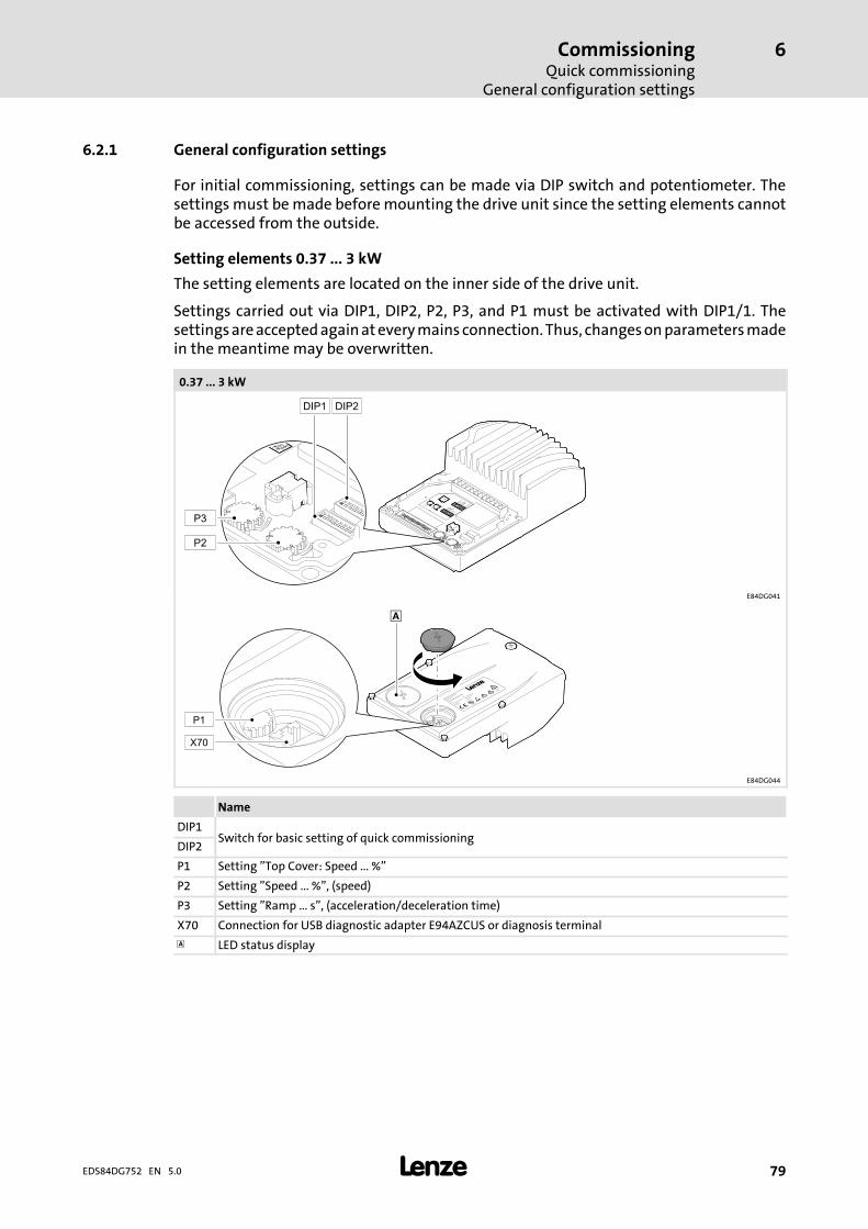
CommissioningQuick commissioning
General configuration settings
6
79EDS84DG752 EN 5.0
6.2.1 General configuration settings
For initial commissioning, settings can be made via DIP switch and potentiometer. Thesettings must bemade before mounting the drive unit since the setting elements cannotbe accessed from the outside.
Setting elements 0.37 ... 3 kW
The setting elements are located on the inner side of the drive unit.
Settings carried out via DIP1, DIP2, P2, P3, and P1 must be activated with DIP1/1. Thesettingsareacceptedagainateverymains connection.Thus, changesonparametersmadein the meantime may be overwritten.
0.37 ... 3 kW
E84DG041
E84DG044
Name
DIP1Switch for basic setting of quick commissioning
DIP2
P1 Setting ”Top Cover: Speed ... %”
P2 Setting ”Speed ... %”, (speed)
P3 Setting ”Ramp ... s”, (acceleration/deceleration time)
X70 Connection for USB diagnostic adapter E94AZCUS or diagnosis terminal
LED status display
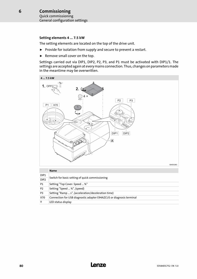
CommissioningQuick commissioningGeneral configuration settings
6
80 EDS84DG752 EN 5.0
Setting elements 4 ... 7.5 kW
The setting elements are located on the top of the drive unit.
ƒ Provide for isolation from supply and secure to prevent a restart.
ƒ Remove small cover on the top.
Settings carried out via DIP1, DIP2, P2, P3, and P1 must be activated with DIP1/1. Thesettingsareacceptedagainateverymains connection.Thus, changesonparametersmadein the meantime may be overwritten.
4 ... 7.5 kW
E84DG083
Name
DIP1Switch for basic setting of quick commissioning
DIP2
P1 Setting ”Top Cover: Speed ... %”
P2 Setting ”Speed ... %”, (speed)
P3 Setting ”Ramp ... s”, (acceleration/deceleration time)
X70 Connection for USB diagnostic adapter E94AZCUS or diagnosis terminal
LED status display

CommissioningQuick commissioning
General configuration settings
6
81EDS84DG752 EN 5.0
Possible settings with DIP1 (Lenze setting bold)
DIP1 Switch
Description 1 2 3 4 5 6 7 8
Settings after DIP1, DIP2, P1, P2, andP3 active
on ( I ) ON
off ( 0 ) OFF
Direction of rotation left ON
right OFF
Control quadratic ON
linear OFF
Flying restart circuit on ( I ) ON
off ( 0 ) OFF
Reserved - OFF OFF OFF
Message type -> on(only optional with CommunicationUnit ”+ Safety”)
fail -> DOready -> NO (relay)
ON
ready -> DOfail -> NO (relay)
OFF
Possible settings with DIP2
DIP2 Switch
Description 1 2 3 4 5 6 7 8
Rated motor frequency 50 Hz OFF OFF
60 Hz ON OFF
87 Hz OFF ON
120 Hz ON ON
Mode of the analog input(only optional with CommunicationUnit ”+ Safety”)
0 ... 10 V OFF OFF
0 ... 20 mA ON OFF
4 ... 20 mA OFF ON
not permissible ON ON
Control mode of technologyapplication(cf. selection C00007)
9 (local mode) OFF OFF OFF
10 (terminals 0) ON OFF OFF
12 (terminals 2) OFF ON OFF
14 (terminals 11) ON ON OFF
16 (terminals 16) OFF OFF ON
Reserved ON OFF ON
Reserved OFF ON ON
40 (MCI) ON ON ON
Reserved - OFF

CommissioningQuick commissioningGeneral configuration settings
6
82 EDS84DG752 EN 5.0
Control modesDIP2/5-7
Description(DIx High)
9(local mode)
The technology application is controlled locally via elements on the controller and the digitalinput terminals:
At mains connection the motor starts up automatically if RFR is bridged or set!
DI1 Setpoint of P2 (speed)Fixed setpoint 3
DI2 Fixed setpoint 2
DI3 Activate DC injection brake
DI4 Change of direction of rotation (not possible if DIP1/2 = on (set to the left))
DI5 Release holding brake manually (operating mode after setting C02580)
10(terminals 0)
The technology application is controlled via the digital input terminals of the controller:
DI1 Fixed setpoint 1Fixed setpoint 3
DI2 Fixed setpoint 2
DI3 Activate DC injection brake
DI4 Change of direction of rotation
DI5 Release holding brake manually (operating mode after setting C02580)
12(terminals 2)
The technology application is controlled via the digital input terminals of the controller:
DI1 Fixed setpoint 1Fixed setpoint 3
DI2 Fixed setpoint 2
DI3 Quick stop
DI4 Change of direction of rotation
DI5 Release holding brake manually (operating mode after setting C02580)
14(terminals 11)
The technology application is controlled via the digital input terminals of the controller:
DI1 Change of direction of rotation
DI2 Activate DC injection brake
DI3 Motor potentiometer: speed higher
DI4 Motor potentiometer: speed lower
DI5 Release holding brake manually (operating mode after setting C02580)
16(terminals 16)
The technology application is controlled via the digital input terminals of the controller:
DI1 Fixed setpoint 1Fixed setpoint 3
DI2 Fixed setpoint 2
DI3 CW rotation/quick stop
DI4 CCW rotation/quick stop
DI5 Release holding brake manually (operating mode after setting C02580)
40(MCI)
The technology application is controlled via fieldbus communication.
Depending on the Communication Unit available

CommissioningQuick commissioning
General configuration settings
6
83EDS84DG752 EN 5.0
Possible settings with P2 ”Speed”
With P2, a motor speed setpoint in percent of the rated speed in C00011 can be preset in10 steps (JOG fixed setpoint). The JOG setpoint is only activated if input DI1 is set in”Local mode”.
P2 Setting
Description 0 1 2 3 4 5 6 7 8 9
Motor speed in percent of the rated speed settingC00011
[%] 0 11 22 33 44 55 66 77 88 100
Possible settings with P3 ”Ramp”
P3 Setting
Description 0 1 2 3 4 5 6 7 8 9
Acceleration or deceleration time of the motor inseconds
[s] 0.1 0.5 1 2 5 10 20 30 60 120
Possible settings with P1
Potentiometer P1 canbeaccessedafter the cover has been removed. In order to ensure thedegree of protection of the controller, the cover has to be screwed in again after thesettings have been made.
During operation, P1 can be used to steplessly set themotor speed in percent of the ratedspeed in C00011 if no JOG fixed setpoint P2 is active via DI1.
P1 Setting
Description 0 ... 9
Motor speed in percent of the rated speed C00011 [%] 0 ... 100

CommissioningQuick commissioningGeneral configuration settings
6
84 EDS84DG752 EN 5.0
Preconditions for initial switch-on
ƒ The wiring unit is mounted and wired according to the instructions,
– directly on a motor clamping flange or
– with the wall adapter on a suitable surface near the motor.
ƒ Connections with the mains, motor, holding brakes, etc. have been established.
ƒ The communication unit has been mounted and wired according to the scheduledapplication.
– Input and output signals
– Safe input
– Fieldbus
(depending on the version, only available optionally)
ƒ If required, the basic settings for ”local mode” have been carried out.
– DIP switches
– Potentiometer
ƒ The drive unit has been mounted and screwed together.
ƒ Use available control functions reasonably, e.g.
– Inhibit controller enable
– Set speed adjustment to the minimum setting
– Activate safety system
ƒ The use of a brake resistor has been checked.
– In the case of dynamic loads or difficult control conditions, the use of the internalbrake resistor E84DZEW47R0 is always recommended for the devicesE84DGDVB4024 ... 7524 (4 ... 7.5 kW).
Danger!High hazard potential during commissioningIncorrect settings may cause unexpected and dangerous motor and systemmovements.Possible consequences:ƒ Damage to material assetsƒ Injury to personsProtective measures:ƒ Clear hazardous areaƒ Observe safety instructions and safety clearances

CommissioningQuick commissioningCommissioning steps
6
85EDS84DG752 EN 5.0
6.2.2 Commissioning steps
Commissioning
Proceed step by step:
ƒ Switch on the mains
ƒ Observe status display
– After a short initialisation time, the display must be blinking green.
ƒ Deactivate requirements of the safety function
ƒ Set controller enable
– After the set starting time, the motor must rotate with the set speed.
ƒ First check of the expected behaviour:
– Direction of rotation?
– Starting time?
– Speed?
– Speed control?
ƒ Check of optional control functions:
– Does the analog setpoint selection work?
– Do the digital control signals, e.g. limit switches, work?
– Does the connected motor holding brake work?
– Does the change of direction of rotation work?
– Does the requirement of the safety function work?
– Do the control signals over fieldbus work?
ƒ Switch off drive
– Reduce speed
– Inhibit controller enable
– Switch off mains
Note!Save parameter settings safe against mains failureIn order to prevent parameter settings carried out in the device from being lostby mains switching, you have to explicitly save the parameter set with mainsfailure protection in the device.

CommissioningHandling of the keypad
6
86 EDS84DG752 EN 5.0
6.3 Handling of the keypad
The keypad X401 serves to quickly and easily set parameters and display current actualvalues and device states by means of the corresponding display parameters. For thispurpose, the keypad must be plugged onto the diagnostic interface on the top of thedevice.
Danger!Uncontrolled motor movement possibleIn general, changing a parameter causes an immediate response in thecontroller.Possible consequences:ƒ This may lead to undesirable behaviour on the motor shaft if the controllerhas been enabled.
Protective measures:ƒMake changes in small steps and wait for response.ƒ Certain device commands or settings which may cause critical states of drivebehaviour constitute exceptions. Such parameter changes are only possibleif the controller is inhibited. Otherwise, a corresponding error message willbe issued.
Note!The keypad can also be inserted/removed during operation.
Further information ....
Further information on the keypad can be found in the operating instructionssupplied with the keypad!
Menu structure
The main menu of the keypad contains the following entries:
Menu item Function
User menu Display of a selection of frequently required parameters.
Code list Display of the parameter list with all parameters.
Go to parameter Directly calls a certain parameter.
Local operation Control of the controller via the keypad keys.
Status Status display (current speed, motor current, device status).

CommissioningHandling of the keypad
6
87EDS84DG752 EN 5.0
User menu
The usermenu can be freely configured in C00517 and contains the following parametersin the Lenze setting:
Parameter Name Info Lenze setting
Value Unit
C00002/19 Device command:Reset error
After resetting the current error, further errors may bepending which must be reset as well.Details of the current error are displayed in C00166.
0 -
C00007 Control mode Selection of how the application is to be controlled. 10 -
C00011 Appl.: Referencespeed
Setting the reference speed 1500 rpm
C00012 Accel. time - mainsetpoint
FB L_NSet_1: Acceleration time of the ramp generatorfor the main speed setpoint
2.0 s
C00013 Decel. time - mainsetpoint
FB L_NSet_1: Deceleration time of the ramp generatorfor the main speed setpoint
2.0 s
C00015 VFC: V/f basefrequency
V/f base frequency for VFCplus motor control 50 Hz
C00016 VFC: Vmin boost Boost of the V/f voltage characteristic within therange of low speed or frequency values for theVFCplus motor control.
2.6 %
C00022 Imax in motor mode Maximum current in motor mode for all motor controlmodes
5.8 A
C00039/1 Fixed setpoint 1(L_NSet_1 n-Fix)
FB L_NSet_1: Fixed speed setpoints (JOG values) forthe setpoint generatorFixed setpoint 1
40.0 %
C00039/2 Fixed setpoint 2 Fixed setpoint 2 60.0 %
C00039/3 Fixed setpoint 3 Fixed setpoint 3 80.0 %
C00087 Rated motor speed This value can be obtained from the motor nameplate.After the motor to be used has been selected from themotor catalogue,the suitable value can be entered automatically.
1320 rpm
C00089 Rated motorfrequency
This value can be obtained from the motor nameplate.After the motor to be used has been selected from themotor catalogue,the suitable value can be entered automatically.
50 Hz
C00105 Deceleration time -quick stop
The set deceleration time determines the ramp slopeat quick stop
5.0 s
C00120 Motor overloadthreshold (I2xt)
Operating threshold for the error message ”OC6:Motor overload (I2xt)”
100 %
C00129 Value brake resistor Resistance value of the connected brake resistor 220
C00165 Error information Display of the error numbers divided into sectors inthe case of an error
- -
C00173 Mains voltage Selection of the mains voltage for operating thedevice.
0: 400 V -
C02580 Holding brake:Operating mode
Selection of the operating mode for holding brakecontrol
0: Off -

CommissioningHandling of the keypad
6
88 EDS84DG752 EN 5.0
General operation
1. Select the desired menu using the navigation key/.
– The navigation keys/ serve to get one menu level higher/lower.
– The function key serves to get back to the main menu.
2. Select the parameter you want to set within a submenu using the navigation keys/.
3. Press the function key to change to the editing mode.
4. Set the desired value by means of the navigation keys.
– Use the navigation keys/ to move the cursor to the left/right.
– Use the navigation keys/ to change the marked digits.
5. Press the function key to accept the change carried out and quit the editingmode.
– Use the function key to quit the editing mode without accepting the changes.
Tip!Information on how to set parameters with the »Engineer«can be found in the »Engineer« online help.

CommissioningOverview of the commissioning steps with keypad
Keypad control
6
89EDS84DG752 EN 5.0
6.4 Overview of the commissioning steps with keypad
Note!The following can be used at the diagnostic interface X70:ƒ Diagnosis terminal X401 (EZAEBK2003)– The described settings with the keypad X401 can also be carried out withthe diagnosis terminal X401.
ƒ USB diagnostic adapter (E94AZCUS)
6.4.1 Keypad control
Only some parameters must be adapted for the drive. Then the drive application can becontrolled immediately in thepreset controlmode”Terminals 0”via thedigital andanaloginputs at the controller. Alternatively, the keypad can be used for defining the requiredsetpoints and control signals in the ”Keypad” control mode.
Commissioning steps
1. Wiring of power terminals
– Make use of the mounting instructions supplied with the controller to wire thepower terminals according to the requirements of your device.
2. Wiring of control terminals.
– The preconfigured I/O connection can be changed via configuration parameters.See chapter ”User-defined terminal assignment”.
– Assignment in the preset control mode ”Terminals 0”:
Terminal Function Info
A1U Setpoint selection 10 V 1500 rpm (with 4-pole motor)general: 10 V 100 % reference speed (C00011)
DI1 JOG 1JOG 3
Selection of fixed setpoints 1 ... 3 If both inputs are on LOW level, the setpoint selection via the
analog input A1U is active.DI2 JOG 2
DI3 DCB Manual DC-injection braking (DCB) For HIGH-active inputs, DC-injection braking is active as long as
DI3 is at HIGH level. After the hold time (C00107) has expired, the controller sets the
pulse inhibit (CINH). DC-injection braking (ƒÎ 110)
DI4 R/L LOW level: CW rotationHIGH level: CCW rotation
DI5 Holding brake Open/close holding brake Braking modes C02580
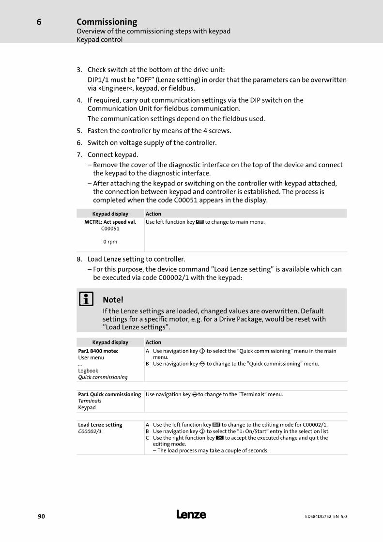
CommissioningOverview of the commissioning steps with keypadKeypad control
6
90 EDS84DG752 EN 5.0
3. Check switch at the bottom of the drive unit:
DIP1/1must be ”OFF” (Lenze setting) in order that the parameters can be overwrittenvia »Engineer«, keypad, or fieldbus.
4. If required, carry out communication settings via the DIP switch on theCommunication Unit for fieldbus communication.
The communication settings depend on the fieldbus used.
5. Fasten the controller by means of the 4 screws.
6. Switch on voltage supply of the controller.
7. Connect keypad.
– Remove the cover of the diagnostic interface on the top of the device and connectthe keypad to the diagnostic interface.
– After attaching the keypad or switching on the controller with keypad attached,the connection between keypad and controller is established. The process iscompleted when the code C00051 appears in the display.
Keypad display Action
MCTRL: Act speed val.C00051
0 rpm
Use left function key to change to main menu.
8. Load Lenze setting to controller.
– For this purpose, the device command ”Load Lenze setting” is available which canbe executed via code C00002/1 with the keypad:
Note!If the Lenze settings are loaded, changed values are overwritten. Defaultsettings for a specific motor, e.g. for a Drive Package, would be reset with”Load Lenze settings”.
Keypad display Action
Par1 8400 motecUser menu...LogbookQuick commissioning
A Use navigation key to select the ”Quick commissioning” menu in the mainmenu.
B Use navigation key to change to the ”Quick commissioning” menu.
Par1 Quick commissioningTerminalsKeypad
Use navigation keyto change to the ”Terminals” menu.
Load Lenze settingC00002/1
A Use the left function key to change to the editing mode for C00002/1.B Use navigation key to select the ”1: On/Start” entry in the selection list.C Use the right function key to accept the executed change and quit the
editing mode.– The load process may take a couple of seconds.
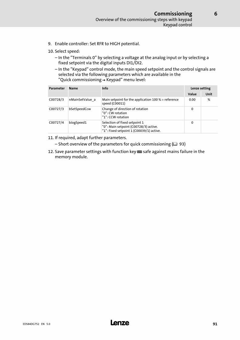
CommissioningOverview of the commissioning steps with keypad
Keypad control
6
91EDS84DG752 EN 5.0
9. Enable controller: Set RFR to HIGH potential.
10. Select speed:
– In the ”Terminals 0” by selecting a voltage at the analog input or by selecting afixed setpoint via the digital inputs DI1/DI2.
– In the ”Keypad” control mode, the main speed setpoint and the control signals areselected via the following parameters which are available in the”Quick commissioning Keypad” menu level:
Parameter Name Info Lenze setting
Value Unit
C00728/3 nMainSetValue_a Main setpoint for the application 100 % referencespeed (C00011)
0.00 %
C00727/3 bSetSpeedCcw Change of direction of rotation”0”: CW rotation”1”: CCW rotation
0
C00727/4 bJogSpeed1 Selection of fixed setpoint 1”0”: Main setpoint (C00728/3) active.”1”: Fixed setpoint 1 (C00039/1) active.
0
11. If required, adapt further parameters.
– Short overview of the parameters for quick commissioning ( 93)
12. Save parameter settings with function key safe against mains failure in thememory module.
CommissioningOverview of the commissioning steps with keypadKeypad control
6
92 EDS84DG752 EN 5.0
Note!In the Lenze setting, the V/f characteristic control (VFCplus) with linearcharacteristic is set in C00006 as motor control.ƒ The V/f characteristic control (VFCplus) is an operating mode for standardfrequency inverter applications based on a simple and robust controlprocess which is suitable for the operation of machines with linear orsquare-law load torque characteristic (e.g. fans).
ƒ The parameter settings have been set in advance in such a way that, if thedrive controller and 50 Hz asynchronous machine match each other in termsof performance, the drive controller is immediately ready for operationwithout any further parameter setting work and the motor workssatisfactorily.
Tip!Recommendations for the following application cases:ƒ If the controller and motor differ greatly from each other in terms ofperformance: Set the Imax limit (in motor mode) in C00022 to double therated motor current.
ƒ If a higher starting torque is required: In idle state of the motor, set theVmin boost in C00016 in such a way that the rated motor current flows at afield frequency of f = 3 Hz (display in C00058).
ƒ For noise optimisation: As switching frequency in C00018, set the selection”3: 16 kHz var./drive-optimised”.
ƒ If a high torque is to be available at low speed and without a feedback:Select the ”vector control (SLVC)” mode in C00006 as motor control.

CommissioningOverview of the commissioning steps with keypad
Short overview of the parameters for quick commissioning
6
93EDS84DG752 EN 5.0
6.4.2 Short overview of the parameters for quick commissioning
The keypad menu ”Quick commissioning” provides access to all essential parameters tocommission the drive/application ”Speed actuating – drive” quickly and easily. Whenthese parameters are set to suitable and sensible values, an error-free operation of thecontroller is possible.
ƒ The ”Terminals” submenu contains the parameters for a control via terminals.
ƒ The ”Keypad” submenu contains the parameters for a control via keypad.
Parameter Keypad display Info Lenze setting Available in the submenu
Value Unit ”Terminals” ”Keypad”
C00002/1 Load Lenze setting Load Lenze setting 0: Off / ready
C00007 Select control mode Select control mode 10: Terminals 0
C00728/3 nMainSetValue_a Main setpoint 0.00 % -
C00011 Appl.: Reference speed Reference speed 1500 rpm
C00012 Accel. time - mainsetpoint
Acceleration time - mainsetpoint 2,000 s
C00013 Decel. time - mainsetpoint
Deceleration time -main setpoint 2,000 s
C00015 VFC: V/f base frequency V/f base frequency 50.0 Hz
C00016 VFC: Vmin boost Vmin boost 2.60 %
C00022 Imax (motor mode) Current limit (in motormode) 5.8 A
C00087 Rated motor speed Rated motor speed 1320 rpm
C00089 Rated motor freq. Rated motor frequency 50 Hz
C00039/1 Fixed setpoint 1 Fixed setpoint 1 40.00 %
C00039/2 Fixed setpoint 2 Fixed setpoint 2 60.00 % -
C00039/3 Fixed setpoint 3 Fixed setpoint 3 80.00 % -
C00727/3 bSetSpeedCcw Change of direction ofrotation 0 -
C00727/4 bJogSpeed1 Selection of fixedsetpoint 1 0 -
C00051 MCTRL: Act. speed val. Actual speed value - rpm
C00054 Motor curr. Current motor current - A
Display codes are shown in italics.

CommissioningSetting with the diagnosis terminal (keypad)
6
94 EDS84DG752 EN 5.0
6.5 Setting with the diagnosis terminal (keypad)
The controller can also be set and controlled with the diagnosis terminal. The diagnosisterminal consists of a molded recess, connecting cable and the keypad which cannot bedirectly plugged onto the controller. Descriptions for the keypad can be done with thediagnosis terminal.
When the diagnosis terminal is connected, a preselected parameter is displayed afterinitialisation. In the Lenze setting, the actual speed value (C00051) is displayed. Thepreselected parameter can be changed (C00466).
”SET” mode
The right softkey ”SET” serves to change fromthedisplaymode to the SETmode. In the SETmode, the speed setpoint can be changed and the controller can be enabled/inhibited(RFR/run). TheSETmodecanbequitwith the right softkey”DISP”. Thechangeof themodesmust always be confirmed with the right softkey ”OK”.

CommissioningDiagnostics
Drive diagnostics via the integrated display
6
95EDS84DG752 EN 5.0
6.6 Diagnostics
6.6.1 Drive diagnostics via the integrated display
On the top side of the Drive Unit, a green/red LED display indicates the respectiveoperating status of the controller. The LED shines brightly through the transparent cap.
LED status display
Description green red
Mains off off off
Switch-on phase (initialisation) (shining yellow) on on
Operation or motor data identification on
offController inhibited (RFR) blinking
Safety function active (Safe torque off) flashing
Controller is ready (initialisation completed) flashing twice
Operation with warning active onblinking
flashing twiceflashes every 3 s
Quick switch-off active on flashing
System error
off
on
Error blinking
Message is active flashing
LED flashes once approx. every 3 seconds (slow flash)
LED flashes once approx. every 1.25 seconds (flash)
LED flashes twice approx. every 1.25 seconds (double flash)
LED blinks every second
LED is permanently on
6.6.2 Diagnostic codes
Important codes for diagnostics
In addition to the keypad, also use the LEDs on the front of the controller for drivediagnostics:
ƒ Two LEDs indicate the device status (DRIVE READY and DRIVE ERROR)
ƒ Two LEDs indicate the bus status (CAN-RUN and CAN-ERROR)
The LEDs for the bus status are less important during quick commissioning.
Tip!The handling of the keypad X401 or the diagnosis terminal X401 is describedin the operating instructions. The instructions are supplied with the keypadand are also included in electronic form on the product CD ”L-force InverterDrives 8400”.
Braking operationBraking operation without additional measures
7
96 EDS84DG752 EN 5.0
7 Braking operation
7.1 Braking operation without additional measures
DC injection brake DCB
To decelerate small masses, the ”DC injection brake DCB” function can be parameterised.DC-injection braking enables a quick deceleration of the drive to standstill without theneed for an external brake resistor.
ƒ Code C00036 can be used to select the braking current.
ƒ The maximum braking torque to be realised by the DC braking current amounts toapprox. 20 ... 30 % of the rated motor torque. It is lower compared to braking actionin generator mode with external brake resistor.
ƒ Automatic DC-injection braking (Auto-DCB) improves the starting performance ofthe motor when the operation mode without speed feedback is used.
Further information on the relevant parameters can be obtained from the softwaremanual.

Braking operationBraking operation with brake resistor
Selection of the brake resistors
7
97EDS84DG752 EN 5.0
7.2 Braking operation with brake resistor
To decelerate greater moments of inertia or with a longer operation in generator mode, abrake resistor is required. It converts braking energy into heat.
Thebrake resistor is connected if theDC-bus voltageexceeds the switching threshold. Thisprevents the controller from setting pulse inhibit through the ”Overvoltage” fault and thedrive from coasting. The brake resistor serves to control the braking process at any time.
Options with 8400 motec:
1. There is no internal brake resistor integrated in the device. Braking energy cannot beconverted into heat.
2. An internal brake resistor can optionally be attached from the correspondingaccessories ( 114). This enables the conversion of small amounts of brakingenergy into heat, according to the technical data.
3. An external brake resistor can optionally be attached from the accessories ( 115).This enables the conversion of braking energy into heat, according to the technicaldata.
7.2.1 Selection of the brake resistors
The recommended Lenzebrake resistors are adapted to the corresponding controller (withregard to 150 % of regenerative power). They are suitable for most of the applications.
For special applications, e.g. centrifuges, the brake resistor must meet the followingcriteria:
Brake resistor Application
Criterion With active load With passive load
Continuous braking power[W]
≥ Pmax ⋅ ηe ⋅ ηm ⋅t1tzykl
≥Pmax ⋅ ηe ⋅ ηm
2⋅
t1tzykl
Heat quantity [Ws] ≥ Pmax ⋅ ηe ⋅ ηm ⋅ t1 ≥Pmax ⋅ ηe ⋅ ηm
2⋅ t1
Resistance [] Rmin≤ R≤UDC
2
Pmax ⋅ ηe ⋅ ηm
Active load Can start to move independent of the drive(e.g. unwinder)
Passive load Can stop independent of the drive(e.g. horizontal travelling drives, centrifuges, fans)
VDC [V] Switching threshold of brake chopper (8400 motec = 783 V)
Pmax [W] Maximum occurring braking power determined by the application
e Electrical efficiency (controller + motor)Guide value: 0.54 (0.25 kW) ... 0.85 (11 kW)
m Mechanical efficiency (gearbox, machine)
t1 [s] Braking time
tcycl [s] Cycle time = time between two successive braking processes (= t1 + dead time)
Rmin [] Minimum permissible brake resistance (see rated data of the integrated brake chopper)

Braking operationBraking operation with brake resistorWiring of brake resistor
7
98 EDS84DG752 EN 5.0
7.2.2 Wiring of brake resistor
Danger!Hazardous electrical voltageDuring operation of the standard device and up to 3 minutes after power-offhazardous electrical voltages may occur at the terminals of the brake resistor.Possible consequences:ƒ Death or severe injuries when touching the terminals.Protective measures:ƒ Disconnect the standard device from the mains before working on the brakeresistor.
ƒ Check all power terminals for isolation from supply.ƒ Select the mounting location so that the operating conditions mentioned inthe mounting instructions for the brake resistor are permanentlyguaranteed.
Danger!Hot surfaceThe brake resistor may get very hot. (For temperatures see the mountinginstructions for the brake resistor.)Possible consequences:ƒ Severe burns when touching the brake resistor.ƒ Fire or smouldering fire if flammable material is placed near the brakeresistor or may get to it.
Protective measures:ƒ Before working on the brake resistor, check its surface temperature.ƒ Select the mounting location so that the operating conditions mentioned inthe mounting instructions for the brake resistor are permanentlyguaranteed.
ƒ Protect the mounting location through fire prevention.
Protect the brake resistor and controller against destruction caused by overload:
ƒ Establish a safety shutdown using the thermostat of the brake resistor to disconnectthe controller from the mains.
Connecting cable version
ƒ up to 0.5 m: twisted and unshielded
ƒ from 0.5 to 5 m: shielded
– Use shielded cables to meet the EMC requirements.

Braking operationBraking operation with brake resistor
Wiring of brake resistor
7
99EDS84DG752 EN 5.0
Wiring principle
�
RB
RB1 RB2
<0.
5m
PE
T1 T2
�
RB
RB1 RB2
<5
m
PE
PES
PES
T1 T2
� �ERBG008 ERBG007
Fig. 7-1 Wiring of a brake resistor to the controller
PES HF-shield termination by PE connection via shield clampRb1, Rb2 Terminals of the brake resistor Supply cable to the controllerT1, T2 Terminals temperature monitoring of the brake resistor (thermal contact/NC
contact) Supply cable for evaluation of temperature monitoring
(to be integrated e.g. into the latch circuit of the mains contactor of the supply)
The brake resistor is thermally stressed due to converted braking power and may bethermally destroyed as a consequence of excessive braking power.
To avoid thermal overload of the brake resistor:
ƒ set additional parameters in the »Engineer«
or
ƒ implement external wiring using a temperature contact on the brake resistor (e.g.interrupted supply and activation of the mechanical brakes).
To protect the brake resistor:
ƒ use the monitoring of the I2xt utilisation of the controller which is proportional tothe converted braking power.

Braking operationBraking operation with brake resistorWiring of brake resistor
7
100 EDS84DG752 EN 5.0
Evaluation of the thermal contact via digital input
The integration of the thermal contact for monitoring the brake resistor can beimplemented via digital input. Use a Lenze system cable. The response to the input signalmust be parameterised using the »Engineer«.
0.37 ... 3 kW 4 ... 7.5 kW
GND-IO
GIO24O
3.3
k
3.3
k
RB2RB1 T1 T2
ERB...E84D...
Rb2Rb1X4 X1DIxDI...
GND-IO
GIO24O
3.3
k
3.3
k
RB2RB1 T1 T2
ERB...E84D...
Rb2Rb1X4 X2DIxDI...
8400DDI032 b 8400DDI032 c
E84D... 8400 motecX4/DIx free digital inputX1/Rb1,Rb2 Connection of the brake resistor for devices 0.37 ... 3 kWX2/Rb1,Rb2 Connection of the brake resistor for devices 4 ... 7.5 kWERB... Brake resistor

Braking operationOperation with spring-applied brake
Introduction
7
101EDS84DG752 EN 5.0
7.3 Operation with spring-applied brake
7.3.1 Introduction
Lenze three-phase AC motors and G-motion geared motors can be equipped withspring-applied brakes (motor holding brakes). 8400 motec controllers are provided withan integrated motor brake control.
Switching the brake
The voltage required for controlling the motor brake is generated in the controller,depending on the mains voltage value. The following motor brakes can be connected:
ƒ With 400-V mains: Coil voltage 180 V DC
ƒ With 480-V mains: Coil voltage 215 V DC
Optionally, the switching of the brake can be controlled in addition:
ƒ Via an external control contact (e.g. PLC)
ƒ Via a brake switch which is connected to one of the digital outputs of the controller.The digital output must be parameterised accordingly.
The software manual provides further information on the parameterisation andintegrated brake management.
7.3.2 Wiring
The cable of the motor holding brake can be routed directly by means of a cable gland inparallel to the motor axis.
The motor holding brake is connected to BD1 (+) and BD2 (-).
0.37 ... 3 kW 4 ... 7.5 kW
X1 BD1BD2 L1 L2 L3 Rb1Rb2 U V W T2 T1BD1BD2
+-
X2 BD1BD2 Rb1Rb2U V W T2T1BD1BD2
+ -
E84DG040 BD E84DG078
X1 Terminal in theWiring Unit for devices 0.37 ... 3 kWX2 Terminal in theWiring Unit for devices 4 ... 7.5 kWBD1 Connection of spring-applied brake +BD2 Connection of spring-applied brake - HF-shield termination by large surface connection to PE. Earthing (PE)
Safety engineeringIntroduction
8
102 EDS84DG752 EN 5.0
8 Safety engineering
8.1 Introduction
With increasing automation, protection of persons against hazardous movements isbecomingmore important. Functional safety describes themeasures needed bymeans ofelectrical or electronic equipment to reduce or remove danger caused by failures.
Duringnormaloperation, safetyequipmentpreventspeopleaccessinghazardousareas. Incertain operating modes, e.g. set-up mode, work needs to be carried out in hazardousareas. In these situations themachine operatormust be protected by integrated drive andcontrol measures.
Drive-basedsafetyprovides theconditions in thecontrols anddrives tooptimise thesafetyfunctions. Planning and installation expenditure is reduced. In comparison to the use ofstandard safety engineering, drive-based safety increases machine functionality andavailability.
Drive-based safety with Inverter Drives 8400
Decentralised drives are frequency inverters that are not mounted locally like controlcabinet devices but are directly attached to the application in the field. Thisproduct-specific feature results in high demands regarding robustness and class ofprotection.
The 8400 motec controllers are optionally available with an integrated safety system.
”Integrated safety” stands for application-oriented safety functions that are applicable onmachines for the protection of persons.
The motion functions continue to be executed by the controller. The integrated safetysystem monitors the safe compliance with the limit values and provides the safe inputsand outputs. If limit values are exceeded, the integrated safety system starts controlfunctions according to EN 60204-1 directly in the controller for the case of an error.
The safety functions are suitable for applications according to IEC 61508 to SIL 3 andachieve the performance level (PL)e according to EN ISO 13849-1. The requirements of thestandard EN 954-1 valid until 30 November 2009 are met until control category 4.

Safety engineeringImportant notes
8
103EDS84DG752 EN 5.0
8.2 Important notes
Application as directed
The controllers that are equipped with safety engineering must not be modified by theuser. This concerns the unauthorised exchange or removal of the safety engineering.
Danger!Danger to life through improper installationImproper installation of safety engineering systems can cause an uncontrolledstarting action of the drives.Possible consequences:ƒ Death or severe injuriesProtective measures:ƒ Safety engineering systems may only be installed and commissioned byqualified and skilled personnel.
ƒ All control components (switches, relays, PLC, ...) and the control cabinetmust comply with the requirements of ISO 138491 and ISO 13849-2. Thisincludes i.a.:– Switches, relays with at least IP54 enclosure.– Control cabinet with at least IP54 enclosure.– Please refer to ISO 138491 and ISO 13849-2 for all further requirements.
ƒ Wiring must be shielded.ƒ All safety relevant cables outside the control cabinet must be protected, e.g.by means of a cable duct:– Ensure that no short circuits can occur.– For further measures see EN ISO 13849-2.
ƒ If an external force acts upon the drive axes, additional brakes are required.Please observe that hanging loads are subject to the force of gravity!
Danger!When the ”safe torque off” (STO) function is used, an ”emergencyswitching-off” according to EN 60204 is not possible without additionalmeasures. There is no electrical isolation, no service switch or repair switchbetween motor and controller!“Emergency switching-off” requires an electrical isolation, e.g. by a centralmains contactor!
Safety engineeringImportant notesHazard and risk analysis
8
104 EDS84DG752 EN 5.0
During operation
After the installation is completed, the operator must check the wiring of the safetyfunction.
The functional testmust be repeated at regular intervals. The time intervals to be selecteddepend on the application, the entire system and the corresponding risk analysis. Theinspection interval should not exceed one year.
Residual hazards
In case of a short-circuit of two power transistors a residualmovement of themotor of upto 180 °/number of pole pairs may occur! (Example: 4-pole motor residual movementmax. 180 °/2 = 90 °)
This residual movement must be considered in the risk analysis, e.g. safe torque off formain spindle drives.
8.2.1 Hazard and risk analysis
This documentation can only accentuate the need for hazard analysis. The user of theintegrated safety systemmust read up on standards and the legal situation:
Before the launch of amachine, themanufacturer of themachinemust conduct a hazardanalysis according to Machinery Directive 2006/42/EC to determine the hazardsassociated with the application of the machine. The Machinery Directive refers to threebasic principles for the highest possible level of safety:
ƒ Hazard elimination / minimisation by the construction itself.
ƒ Required protective measures must be taken against hazards which cannot beeliminated.
ƒ Existing residual hazards must be documented and the user must be informed ofthem.
Detailed information on the hazard analysis procedure is provided in the EN 1050, riskassessment principles. The results of the hazard analysis determine the category forsafety-related control systems according to EN ISO 13849-1. Safety-oriented parts of themachine control must be compliant.
8.2.2 Standards
Safety regulations are confirmed by laws and other governmental guidelines andmeasures and the prevailing opinion among experts, e.g. by technical regulations.
The regulations and rules to be applied must be observed in accordance with theapplication.

Safety engineeringBasics for safety sensors
8
105EDS84DG752 EN 5.0
8.3 Basics for safety sensors
Passive sensors
Passive sensors are two-channel switching elementswith contacts. The connecting cablesand the sensor function must be monitored.
The contacts must switch simultaneously (equivalently). Nevertheless, safety functionswill be activated as soon as at least one channel is switched.
The switches must be wired according to the closed-circuit principle.
Examples of passive sensors:
ƒ Door contact switch
ƒ Emergency-off control units
Active sensors
Active sensors are units with 2-channel semiconductor outputs (OSSD outputs). With theintegrated safety system of this device series, test pulses < 1 ms for monitoring theoutputs and cables are permissible. Themaximally permissible connection capacity of theoutputs is to be observed.
P/M-switching sensors switch the positive and negative cable or the signal and groundwire of a sensor signal.
The outputs have to switch simultaneously. Nevertheless, safety functions are triggeredas soon as at least one channel is switched.
Examples of active sensors:
ƒ Lightgrid
ƒ Laser scanner
ƒ Control systems

Safety engineeringOperating modeIntroduction
8
106 EDS84DG752 EN 5.0
8.4 Operating mode
8.4.1 Introduction
Due to safety option 10, the following safety functions can be used:
ƒ Safe torque off (STO),formerly: safe standstill
If requested, the safe disconnection of the drive is achieved through:
ƒ Directly connected active sensors
ƒ Passive sensors connected to a safety switching device
The safety functions are suitable for applications according to IEC 61508 to SIL 3 andachieve aperformance level (PL) e and the control category 4 according to EN ISO 13849-1.
Danger!If the request for the safety function is cancelled, the drive will restartautomatically.You must provide external measures which ensure that the drive only restartsafter a confirmation (EN 60204).
8.4.2 Disconnecting paths
The transmission of the pulsewidthmodulation is safely switched (off) by the safety unit.After this, the power drivers do not generate a rotating field. Themotor is safely switchedto torqueless operation (STO).
M
SO
PWM
µCµC
PC
3x
3x
Xxx
E84DPSO02
Fig. 8-1 Operating principle of safety unit
SO Safety option 10xxx Control terminals of the safety system or safety busC Control sectionC MicrocontrollerPWM Pulse width modulationP Power sectionM Motor
Safety engineeringOperating mode
Safety status
8
107EDS84DG752 EN 5.0
8.4.3 Safety status
Whenthecontroller isdisconnected fromthesafetyunit, the”Safe torqueoff” (STO)statusis set (C00155 bit 10 = 1).

Safety engineeringTechnical data
8
108 EDS84DG752 EN 5.0
8.5 Technical data
Supply
The safe input and the output are isolated and designed for a low-voltage supply througha safely separated power supply unit (SELV/PELV) of 24 V DC. PM-switching input signalsand test pulses 1 ms are permissible.
Active sensors are directly connected to X61.
Passive sensors are connected to X61 via a switching device. The switching device mustcomply with the required performance level of the application.
There is no monitoring for short circuits.
Detailed features of the inputs and outputs of the safety unit
Terminal Specification [Unit] min. typ. max.
SIA, SIB Low signal V -3 0 5
High signal V 18 24 30
Input capacitance at switch-off nF 3
Input delay (tolerated test pulse) ms 1
Switch-off time (depending on the controller) ms 2.5 4
Running time ms 3
Input current SIA mA 35 50
Input current SIB mA 25 50
Input capacitance at switch-on F 6
GI GND potential for SIA / SIB and for the unsafesignalling output
24O Supply voltage through safely separated power supplyunit (SELV/PELV) V 18 24 30
DO Low signal V 0 0.8
High signal V 18 24 30
24O, DO Output current A 0.2
Truth table
Safe input / channel Signallingoutput
Controller
SIA SIB DO Description of the device status Enable
0 0 1 ”SafeTorqueOff” activated(safe torque off)
0
0 1 0Fault scenario or impermissible status
0
1 0 0 0
1 1 0 Drive active or ”ReadyToSwitchOn” 1
Note!Safe inputs are designed with 2 channels (...A/...B). The channels must becontrolled separately and simultaneously (in an equivalent manner).The active control of only one channel indicates a faulty sensor system or animpermissible interconnection.

Safety engineeringTechnical data
8
109EDS84DG752 EN 5.0
Restriction of use
The operation of an integrated safety system is not permissible in earthed phase mains.

Safety engineeringElectrical installation
8
110 EDS84DG752 EN 5.0
8.6 Electrical installation
X61 - connection of safety system ”Safety Option 10”
Pin Connection Description
DOSIB GISIAX61 24O
DC 24 V(+19.2 … +28.8 V)
+
-
�
Terminal strip, 5-pole
E84DG027
SIA Safe input, channel A
SIB Safe input, channel B
GI GND potential for SIA/SIBGND potential for the unsafe signalling output
24O 24 V voltage supply for the unsafe signalling output
DO Unsafe signalling output: ”SafeTorqueOff” with a 2-channelrequest by SIA andSIB
X61
E84DG025
X61 a[mm]
[mm2][AWG]
Safety 55
0.5 ... 1.520 ... 16
0.5 ... 1.020 ... 18
0.520
Note!The wiring connected for test purposes to the connections of the safety systemmust be removed (e.g. bridges SIA/SIB at 24O).

Safety engineeringCertification
8
111EDS84DG752 EN 5.0
8.7 Certification
Tip!The ”TÜV Rheinland Group” certificate is available on the Internet under:http://www.Lenze.com

Accessories (overview)Adapter plates (accessories)
9
112 EDS84DG752 EN 5.0
9 Accessories (overview)
9.1 Adapter plates (accessories)
For themounting of the 8400motec separated from themotor, awall adapter is available.
ƒ Wall adapter E84DZMAWE1
Thewall adaptercanbeused insmall spaces. Increasedexpenditure for installation ( 75)due to a suitablemotor cablemust be considered. In addition, an installation according toEMC (structure of the C-typical drive system( 59)) must be considered.
E84DZMA010_a
E84DZMAWE1003 b

Accessories (overview)Plug connectors
9
113EDS84DG752 EN 5.0
9.2 Plug connectors
By default, cables for the connection of the mains and the motor are led into the WU bymeans of cable glands. Alternatively, plug-in modules with prewired Q-plugs can besupplied for mounting on the right or the left.
For plug-inmodules with a Q-plug, anM16 bore for an additional cable gland is available.
Plug-in modules with two Q-plugs are designed for a looping-through connection(daisy-chain). Like this it is possible to use a supply bus for the machine design.
In the case of wall mounting, the plug-in modules with a Q8-plug enable the motorconnection as a plug&drive drive, in particular with Lenze system cables.
In the table the retrofittable plug-in modules are listed.
�X... Umax Imax IP
[V] [A]
E84DZEVBLANP X10: Q5
400 ~ 16 ~
~
IP65
E84DZEVBRANP E84DGDVB3024...
E84DZEVBLAFP X10: Q5X11: Q5 ~ ~
E84DZEVBRAFP E84DGDVB3024...
E84DZEVBLPNP X10: Q4/2
480 ~
24 =
32 ~
10 =
~=
E84DZEVBRPNP
E84DZEVBLPRP X10: Q4/2X11: Q4/2 ~
=~=
E84DZEVBRPRP E84DZEVBLCNP
X21: Q8 480 ~ -E84DZEVBRCNP

Accessories (overview)Internal brake resistors
9
114 EDS84DG752 EN 5.0
9.3 Internal brake resistors
Product key Rated data - brake resistor
Controller Brake resistor ResistorR []
Continuous powerP [W]
Heat quantityQB [kWs]
E84DGDVB3714E84DGDVB5514E84DGDVB7514E84DGDVB1124E84DGDVB1524
E84DZEW220R 220 15 0.6
E84DGDVB2224E84DGDVB3024
E84DZEW100R 100 15 0.6
E84DGDVB4024E84DGDVB5524E84DGDVB7524
E84DZEW47R0 47 15 0.6
E84DZEV010a

Accessories (overview)External brake resistors
9
115EDS84DG752 EN 5.0
9.4 External brake resistors
Product key Rated data - brake resistor
Controller Brake resistor ResistorR []
Continuous powerP [W]
Heat quantityQB [kWs]
E84DGDVB3714
-(MA ERBS470R)
180
600 -
E84DGDVB5514 800 -
E84DGDVB7514 1050 -
E84DGDVB1124 1400 -
E84DGDVB1524 1800 -
E84DGDVB2224- 100
2600 -
E84DGDVB3024 3600 -
E84DGDVB4024
- 47
4800 -
E84DGDVB5524 6600 -
E84DGDVB7524 9000 -

Accessories (overview)Communication modulesCANopen
9
116 EDS84DG752 EN 5.0
9.5 Communication modules
”Communication Units” are the communication modules for the 8400 motec controller.
The controller must at least be provided with the CU ”NO BUS”, E84DGFCNNNx. Thismodule offers a minimum control via two digital inputs.
In order to enable a fieldbus communication, one of the following CU variants must beused.
9.5.1 CANopen
For fieldbus communication via CANopen, the Communication Unit is available in twoversions:
ƒ E84DGFCCxNX (without safety system)
ƒ E84DGFCCxJX (with safety system, additional analog input, and switching contact)
Detailed information on the 8400 motec with CANopen can be found in theEDS84DMOTCAN communication manual.
9.5.2 PROFIBUS
For fieldbus communication via PROFIBUS, the Communication Unit is available in twoversions:
ƒ E84DGFCPxNX (without safety system)
ƒ E84DGFCPxJX (with safety system, additional analog input, and switching contact)
Detailed information on the 8400 motec with PROFIBUS can be found in theEDS84DMOTPBUS communication manual.
9.5.3 AS interface
For fieldbus communication via AS interface, the Communication Unit is available in twoversions:
ƒ E84DGFCAxNX (without safety system)
ƒ E84DGFCAxJX (with safety system, additional analog input, and switching contact)
Detailed information on the 8400 motec with AS interface can be found in theEDS84DMOTASI communication manual.

Accessories (overview)Communication modules
PROFINET
9
117EDS84DG752 EN 5.0
9.5.4 PROFINET
For fieldbus communication via PROFINET, the Communication Unit is available in twoversions:
ƒ E84DGFCRxNX (without safety system)
ƒ E84DGFCRxJX (with safety system, additional analog input and switching contact)
Detailed information on the 8400 motec with PROFINET can be found in theEDS84DMOTPNET communication manual.
9.5.5 EtherCAT
For fieldbus communication via EtherCAT, the Communication Unit is available in twoversions:
ƒ E84DGFCTxNX (without safety system)
ƒ E84DGFCTxJX (with safety system, additional analog input and switching contact)
Detailed information on the 8400 motec with EtherCAT can be found in theEDS84DMOTECAT communication manual.
9.5.6 EtherNet/IP
For fieldbus communication via EtherNet/IP, the Communication Unit is available in twoversions:
ƒ E84DGFCGxNX (without safety system)
ƒ E84DGFCGxJX (with safety system, additional analog input and switching contact)
Detailed information on the 8400 motec with EtherNet/IP can be found in theEDS84AYCEO communication manual.

Accessories (overview)Keypad
9
118 EDS84DG752 EN 5.0
9.6 Keypad
Checking or changing parameters by experienced users can be executed by means of akeypad X401, diagnosis terminal version.
ƒ Diagnosis terminal X401, EZAEBK2003
Thediagnosis terminal canbe connected to thediagnostics interface X70on the topof the8400 motec.
Chapters 6.3 - 6.5 describe the handling and setting using a keypad for 8400 motec.
Further information on the keypad can be found in the instructions supplied with thedevice.

Accessories (overview)Safety engineering
9
119EDS84DG752 EN 5.0
9.7 Safety engineering
8400 motec controllers can optionally be provided with integrated safety engineering.This requires an extended Communication Unit.
The version provided with safety engineering is clearly designated in the E84DGFCxxJxtype key.
Detailed information on integrated safety can be found in the chapter ”Safetyengineering” ( 102).

AppendixTotal index
10
120 EDS84DG752 EN 5.0
10 Appendix
10.1 Total index
0 ... 98400 motec Set, motec Set, 24
AAccessories, 112
- Brake resistor, 97
Ambient conditions
- climatic, 28
- mechanical, 28
Analog input, 50
BBrake resistor
- Selection, 97
- Wiring, 98
Braking, 96
Braking operation, 96
- DC injection brake DCB, 96
- with brake resistor, 97
- without additional measures, 96
CCable
- For control connections, 61
- for the motor connection, 60
Cables
- cross-sections, 34, 36, 38
- fuses, 34, 36, 38
CANopen, 116
Commissioning, 76
- per keypad, overview, 89
Communication connection, 51
Communication modules, 116
Communication Unit, 23
Communication, connection, 51
Control cable, 61
Control terminals, 46
DDefinition of notes used, 11
Definitions, Terms, 10
Device protection, 18, 55
Diagnostic codes, 95
Digital inputs, 48
Digital output, 50
Dimensions for wall mounting, 53
Disconnecting paths, 106
Disposal, 14
Drive Unit, 23
- settings, 72
EElectrical installation, 63, 110
- communication connection, 51
- wiring of control connections, 64
EMC, what to do in case of interferences, 61
EN 61000-3-2, 29
Enclosure, 27
FFuses, 34, 36, 38
- operation with rated power, 400 V (UL), 34, 38
GGeneral configuration, 79
HHarmonic currents, limitation according to EN 61000-3-2,29
Hazard analysis, 104
IIdentification, 21
Installation, 54
- electrical, 63, 110
- mechanical, 62
Interferences, eliminating EMC interferences, 61
Introduction, 106
IT system, 74
- measures, 74

AppendixTotal index
10
121EDS84DG752 EN 5.0
KKeypad, 118
MMains current, 33, 35, 37
Mechanical installation, 62
Monitoring, Of the motor temperature, 45
Motor, connection, 45
Motor cable, 60
- length, 28
Motor power, typical, 33, 35, 37
Motor protection, 18
Motor temperature, monitoring, 45
Mounting place, 28
Mounting position, 28
NNameplate, 21
Noise emission, 29
Noise immunity, 29
Notes, definition, 11
OOperating conditions, ambient conditions
- climatic, 28- mechanical, 28
Operation, Overcurrent, 40
Output currents, Switching frequency-dependent, 36
Output power, 33, 35, 37
Output voltage, maximum, 31
Output voltage , 31
Overspeeds, 18
Overview
- Accessories, 112- control terminals, 25- terminals, 42
PPollution, 28
Power system, 28
Power terminals, 44
Product description, 19
Protection of persons, 18
Protective insulation of control circuits, 27
Protective measures, 27
QQuick commissioning, with keypad control, 89
RRated data, Operation at increased rated power, 400 Vmains, 35
Residual hazards, 18, 104
Risk analysis, 104
SSafety, safety engineering, 102
Safety engineering, 102
- application as directed, 103
- Certification, 111
Safety functions, safety instructions, during operation,104
Safety instructions, 12
- definition, 11
- during operation, 104
- layout, 11
Safety status, 107
Sensors, basics, 105
Site altitude, 28
Supply conditions, 28
- mains, 28
- motor, 28
Switching frequency reduction, 39
TTechnical data, 26, 108
- Operation at increased rated power, 400 V mains, 35
Terminals, 42
Terms, definitions, 10
Total index, 120
Type code, finding, 21
UUse in IT systems, 74
AppendixTotal index
10
122 EDS84DG752 EN 5.0
VValidity, documentation, 7
WWall mounting, 75
Wiring, Brake resistor, 98
Wiring of control connections, 64
Wiring Unit, 22


© 12/2014
Lenze Drives GmbHPostfach 10 13 52, D-31763 HamelnBreslauer Straße 3, D-32699 ExtertalGermany
Service Lenze Service GmbHBreslauer Straße 3, D-32699 Extertal
Germany
+49 5154 82-0 008000 2446877 (24 h helpline)
+49 5154 82-2800 +49 5154 82-1112
[email protected] [email protected]
www.lenze.com
EDS84DG752 .Peb EN 5.0 TD15
10 9 8 7 6 5 4 3 2 1