Embed Size (px)
Citation preview

HARDWARE
OPERATION
MANUAL
AFC3000E-HW-1
WARNING
All applicable national and local codes must be followed when installing and operating the equipment detailed in this manual.
FAILURE TO ABIDE BY THESE CODES AND THE SPECIFICATIONS DESCRIBED IN THIS
MANUAL CAN RESULT IN SERIOUS INJURY TO PERSONNEL AND/OR DAMAGE TO THE EQUIPMENT!
Any questions regarding the contents of this document or any related matter should be
directed to FEC INC. at (586) 580-2622, faxed to (586) 580-2620 or emailed to [email protected].
The information set forth in the following document is the property of FEC INC.
This document shall not be released to or copied for any person and/or organization
With out the expressed prior consent of FEC INC.
Unauthorized reproduction or distribution of this manual is strictly prohibited.
Please contact FEC INC. if you require additional copies.
Copyright (C) 2013 FEC Automation Systems. All Rights Reserved.

Thank you for purchasing the AFC3000 Nutrunner System. This instruction manual
describes the procedures for installation, wiring, handling and actions to be taken in case of any failure.
This instruction manual shall be delivered to the end user who operates the equipment. Read all instructions before use and always keep this instruction manual with the
equipment. The product specification and appearance described in this instruction manual is subject to
change without notice. All rights reserved. Any disclosure, copying, distribution or use of the information contained
herein for other than its intended purpose, is strictly prohibited.
◆ It is important for you to read all “Safety Precautions” before using the equipment, and understand and observe all instructions and recommendations included in this manual. ◆ Read all instructions and recommendations included in this manual, understand the functions and performance of this Nutrunner, and correctly use this machine. Always keep this instruction manual with the equipment.
◆ Wirings and parameter settings shall only be conducted by a qualified professional. ◆ Indicate the following on all instruction manuals that use this equipment.
”This equipment is capable of high voltages hazardous to human life.” ◆ Never conduct a withstand voltage test or insulation resistance test on this equipment.
Please confirm the following when unpacking this equipment:
◆ Ensure that you received the correct model, as ordered. ◆ Ensure that there are no missing parts. (Refer the list of system structure) ◆ Check for any damage caused during transportation.
◆ Microsoft and Windows are the registered trade mark of Microsoft Corporation ◆ CompactFlash and CF are the registered trademark of San Disk ◆ GX-Developer is the registered trade mark of Mitsubishi Electric Each company’s trade mark and product trade mark that are not mentioned here are registered. All the product names and company names are each company’s registered trademarks or the trademarks.
Points to check when unpacking
For the safety of operator and equipment
Trademark
Introduction
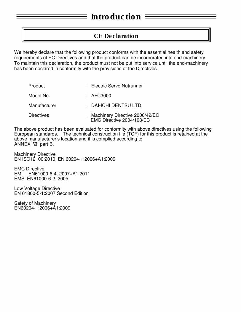
We hereby declare that the following product conforms with the essential health and safety requirements of EC Directives and that the product can be incorporated into end-machinery. To maintain this declaration, the product must not be put into service until the end-machinery has been declared in conformity with the provisions of the Directives.
Product : Electric Servo Nutrunner Model No. : AFC3000 Manufacturer : DAI-ICHI DENTSU LTD. Directives : Machinery Directive 2006/42/EC EMC Directive 2004/108/EC
The above product has been evaluated for conformity with above directives using the following European standards. The technical construction file (TCF) for this product is retained at the above manufacturer’s location and it is complied according to ANNEX Ⅶ part B. Machinery Directive EN ISO12100:2010, EN 60204-1:2006+A1:2009 EMC Directive EMI EN61000-6-4: 2007+A1:2011 EMS EN61000-6-2: 2005 Low Voltage Directive EN 61800-5-1:2007 Second Edition Safety of Machinery EN60204-1:2006+A1:2009
Introduction
CE Declaration
Introduction
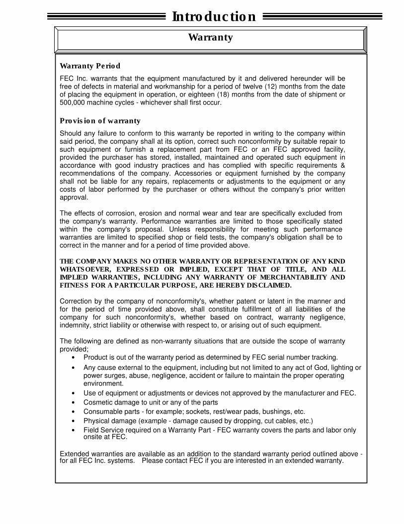
Warranty Period
FEC Inc. warrants that the equipment manufactured by it and delivered hereunder will be free of defects in material and workmanship for a period of twelve (12) months from the date of placing the equipment in operation, or eighteen (18) months from the date of shipment or 500,000 machine cycles - whichever shall first occur.
Provision of warranty
Should any failure to conform to this warranty be reported in writing to the company within said period, the company shall at its option, correct such nonconformity by suitable repair to such equipment or furnish a replacement part from FEC or an FEC approved facility, provided the purchaser has stored, installed, maintained and operated such equipment in accordance with good industry practices and has complied with specific requirements & recommendations of the company. Accessories or equipment furnished by the company shall not be liable for any repairs, replacements or adjustments to the equipment or any costs of labor performed by the purchaser or others without the company's prior written approval. The effects of corrosion, erosion and normal wear and tear are specifically excluded from the company's warranty. Performance warranties are limited to those specifically stated within the company's proposal. Unless responsibility for meeting such performance warranties are limited to specified shop or field tests, the company's obligation shall be to correct in the manner and for a period of time provided above. THE COMPANY MAKES NO OTHER WARRANTY OR REPRESENTATION OF ANY KIND WHATSOEVER, EXPRESSED OR IMPLIED, EXCEPT THAT OF TITLE, AND ALL IMPLIED WARRANTIES, INCLUDING ANY WARRANTY OF MERCHANTABILITY AND FITNESS FOR A PARTICULAR PURPOSE, ARE HEREBY DISCLAIMED. Correction by the company of nonconformity's, whether patent or latent in the manner and for the period of time provided above, shall constitute fulfillment of all liabilities of the company for such nonconformity's, whether based on contract, warranty negligence, indemnity, strict liability or otherwise with respect to, or arising out of such equipment. The following are defined as non-warranty situations that are outside the scope of warranty provided;
• Product is out of the warranty period as determined by FEC serial number tracking.
• Any cause external to the equipment, including but not limited to any act of God, lighting or power surges, abuse, negligence, accident or failure to maintain the proper operating environment.
• Use of equipment or adjustments or devices not approved by the manufacturer and FEC.
• Cosmetic damage to unit or any of the parts
• Consumable parts - for example; sockets, rest/wear pads, bushings, etc.
• Physical damage (example - damage caused by dropping, cut cables, etc.)
• Field Service required on a Warranty Part - FEC warranty covers the parts and labor only onsite at FEC.
Extended warranties are available as an addition to the standard warranty period outlined above - for all FEC Inc. systems. Please contact FEC if you are interested in an extended warranty.
Warranty

Read all instructions before operating the equipment in order to use this equipment safely and correctly.
Prior to use, read this instruction manual carefully and fully understand the equipments functions, safety
precautions and instructions. Safety precautions in this manual are marked with two symbols [Warning]
and [Caution].
To prevent danger to the user and other persons as well as property damage, instructions that must be
fully observed are marked with the symbols below.
◆ This instruction manual uses the following two symbols according to the degree of damage that may be
caused when the instruction is not observed.
Even instructions that are marked with may result in severe damage if they are not
observed according to conditions.
Contents marked with the above symbols are very important instructions. For your safety, follow all
instructions and especially those marked with these symbols.
◆ This instruction manual uses the following additional symbols for instructions that shall be observed.
Warning
Caution
This symbol indicates that failure to observe instruction marked
with this symbol may result in severe personal injury or death.
This symbol indicates that failure to observe instruction marked
with this symbol may result in minor personal injury or material
damage.
Caution
Warning: Fire
Caution: Electric shock
Ground
Prohibited Do not disassemble
Required
Warning: Electric shock
Caution: Fire
Caution: High Temperature
Safety Precautions
Please do not touch the tool to the tool during operation.
Please make sure that the part of the body does not touch the moving parts of the tool. There
is a risk of injury.
Do not remove the motors and gear cases of tools while power is applied..
The tool output spindle may rotate and cause injury.
Do not repair, disassemble, or modify the equipment individual components of the system..
Failure to observe this instruction may cause injury, electric shock, fire, and malfunction.
Never operate the equipment where it is exposed to water, near a corrosive atmosphere
or flammable gases. Failure to observe this instruction may cause fire.
Keep fingers away from the connectors while the equipment is turned ON and for a while after
the equipment is turned OFF. Failure to observe this instruction may cause electric shock.
Wiring operation and maintenance work shall be conducted by a qualified professional.
Failure to observe this instruction may cause electric shock and injury.
Turn OFF the power when conducting wiring operation and maintenance.
Failure to observe this instruction may cause electric shock and injury.
Never damage the cables, apply excess stress to cables, or squeeze the cables.
Never use damaged cables. Failure to observe this instruction may cause electric shock and
fire.
Conduct type-3 grounding of FG terminals.
Failure to observe this instruction may cause electric shock.
In case of an abnormal odor, noise, or operation error occurrence, stop operation immediately
and turn OFF the power source. Failure to observe this instruction may cause injury and fire.
Install a Power shutdown device in order to ensure the safety of equipment.
Failure to observe this instruction may cause injury.
Install an emergency stop circuit on the outside of equipment in order to stop operation
promptly. Failure to observe this instruction may cause injury.
Keep away from the equipment during recovery from a temporary blackout, and ensure safety
measures are conducted after restarting the equipment. The equipment may suddenly restart.
Failure to observe this instruction may cause injury.
Safety Precautions
Warning Transportation / Storage
Transport the equipment properly according to its weight.
Failure to observe this instruction may cause injury and malfunction.
The conditions when transporting the equipment by ship is as below.
◆ Ambient temperature: -5°C~+55°C (Avoid freezing)
◆ Ambient humidity: 50% RH or lower (Avoid moisture)
◆ Package: Tight seal
◆ Rust prevention measure: Apply grease or oil on tools.
Failure to observe this instruction may cause earth leakage and malfunction.
Do not hold cables and output spindles when transporting the tools.
Failure to observe this instruction may cause injury and malfunction.
Do not hold the indictor on the front panel when transporting the Controller (MFC) Unit.
The indicator may come off and drop from the front panel.
Failure to observe this instruction may cause injury and malfunction.
The equipment shall be stored under the following conditions.
◆ Ambient temperature: -5°C~+55°C (Avoid freezing)
◆ Ambient humidity: 85% RH or lower (Avoid moisture)
◆ Atmosphere: Indoors (Avoid direct sunlight)
No corrosive gases or flammable gases
No oil mist, dust, water, salt, iron powder
◆ Avoid direct vibration or shocks
Failure to observe this instruction may cause earth leakage and malfunction.
When discarding, please dispose of as industrial waste.
Caution
Safety Precautions
Transportation / Storage
Install all tools firmly where they can bear the maximum torque during operation.
Failure to observe this instruction may cause injury and malfunction.
Install the Controller (MFC) Unit firmly inside the control panel using the specified screws.
Failure to observe this instruction may cause malfunction.
Use the specified tool for the Controller (MFC) Unit.
Failure to observe this instruction may cause fire and malfunction.
The Controller (MFC) Unit shall maintain the specified distance from other devices.
Failure to observe this instruction may cause fire and malfunction.
Do not block the ventilation hole of the Controller (MFC) Unit.
Avoid any foreign body from entering inside the equipment.
Failure to observe this instruction may cause fire and malfunction.
The power source shall be provided with safety measures such as breakers and
circuit protectors. Failure to observe this instruction may cause fire and malfunction.
Do not use tools or Controller (MFC) Units that are damaged or missing parts.
Failure to observe this instruction may cause fire, injury and malfunction.
Do not get on the top of equipment or do not place heavy objects on the top of equipment.
Failure to observe this instruction may cause injury and malfunction.
Do not subject the equipment to excess shock and impact.
Failure to observe this instruction may cause malfunction.
Conduct wirings properly and firmly.
Failure to observe this instruction may cause injury, false operation, and malfunction.
Operate the equipment within the specified power supply voltage.
Failure to observe this instruction may cause injury, electric shock, fire and malfunction.
When operating the equipment in the following conditions, take sufficient measures
to shield the equipment.
◆Location where electrical noise is generated
◆Location where the equipment is subjected to a strong electric field or magnetic field
◆Location near a high power wire.
Failure to observe this instruction may cause injury, false operation and malfunction.
Caution
Safety Precautions
Installation / Wiring
Never operate the equipment with wet hands.
Failure to observe this instruction may cause electric shock.
Keep fingers away from the Controller (MFC) Unit radiating fin and tool motors while the
equipment is turned ON or for a while after the equipment is turned OFF. These parts may
become very hot. Failure to observe this instruction may cause burns.
Use the equipment under the following conditions.
◆ Ambient temperature: 0°C~+45°C (Avoid freezing)
◆ Ambient humidity: 85% RH or lower (Avoid moisture)
◆ Atmosphere: Indoors (Avoid direct sunlight)
No corrosive gases or flammable gases
No oil mist, dust, water, salt, iron powder
◆ Avoid direct vibration or shocks
Failure to observe this instruction may cause earth leakage and malfunction.
Confirm and adjust all parameters before operation in order to prevent unexpected movement
of the equipment.
Failure to observe this instruction may cause injury, false operation and malfunction.
Never conduct extreme adjustments or setting changes that may cause instability of operation.
Failure to observe this instruction may cause injury, false operation and malfunction.
The equipment may restart suddenly when the equipment is reset with the start signal ON.
Always ensure that the start signal is OFF before resetting the equipment.
Failure to observe this instruction may cause injury.
Do not turn ON and OFF the equipment repeatedly.
Failure to observe this instruction may cause malfunction.
Do not use the equipment at torque higher than the maximum torque.
Failure to observe this instruction may shorten equipment life or cause malfunction
due to the high temperature caused by overload.
In case any abnormality occurs, remove the cause and ensure safety before resetting
and restarting the equipment.
Failure to observe this instruction may cause injury.
Discharge any static electricity in your body before touching the operation switches of the
touch panel and front panel by first touching a grounded conductive object.
Failure to observe this instruction may cause malfunction.
If cleaning the Controller (MFC) Unit or tool use a cloth moistened with warm water or
alchohol. Do not moisten the MFC Unit or tool directly.
Failure to observe this instruction may cause injury.
Caution
Safety Precautions
Operation / Adjustment
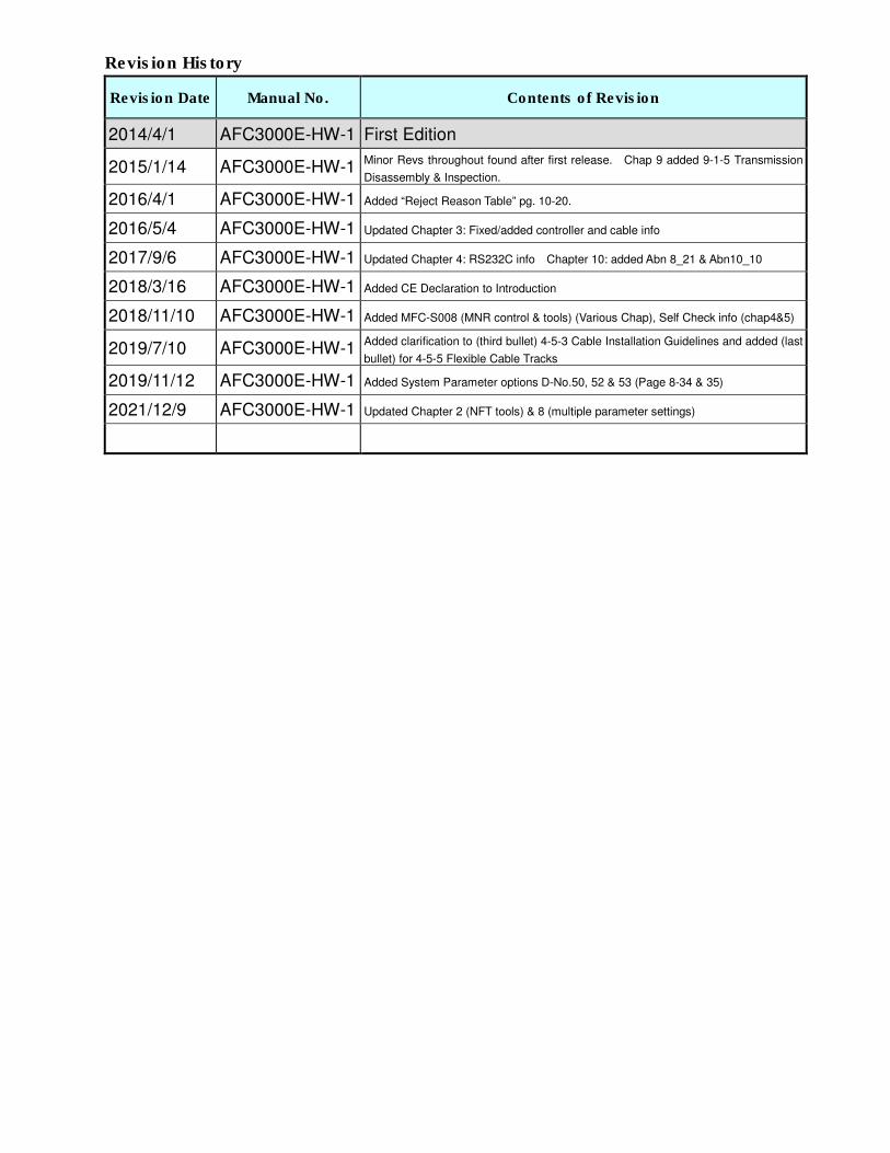
Revision History
Revision Date Manual No. Contents of Revision
2014/4/1 AFC3000E-HW-1 First Edition
2015/1/14 AFC3000E-HW-1 Minor Revs throughout found after first release. Chap 9 added 9-1-5 Transmission
Disassembly & Inspection.
2016/4/1 AFC3000E-HW-1 Added “Reject Reason Table” pg. 10-20.
2016/5/4 AFC3000E-HW-1 Updated Chapter 3: Fixed/added controller and cable info
2017/9/6 AFC3000E-HW-1 Updated Chapter 4: RS232C info Chapter 10: added Abn 8_21 & Abn10_10
2018/3/16 AFC3000E-HW-1 Added CE Declaration to Introduction
2018/11/10 AFC3000E-HW-1 Added MFC-S008 (MNR control & tools) (Various Chap), Self Check info (chap4&5)
2019/7/10 AFC3000E-HW-1 Added clarification to (third bullet) 4-5-3 Cable Installation Guidelines and added (last
bullet) for 4-5-5 Flexible Cable Tracks
2019/11/12 AFC3000E-HW-1 Added System Parameter options D-No.50, 52 & 53 (Page 8-34 & 35)
2021/12/9 AFC3000E-HW-1 Updated Chapter 2 (NFT tools) & 8 (multiple parameter settings)
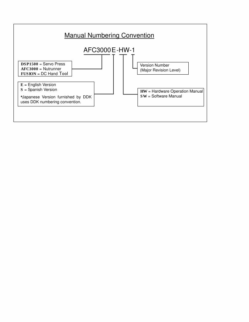
Manual Numbering Convention
AFC3000E-HW-1
DSP1500DSP1500DSP1500DSP1500 = Servo Press
AFC1500AFC1500AFC1500AFC1500 = Nutrunner
FUSIONFUSIONFUSIONFUSION = DC Hand Tool
HW = Hardware Operation Manual
SW = Software Manual
DSP1500 = Servo Press
AFC3000 = Nutrunner
FUSION = DC Hand Tool
E = English Version
S = Spanish Version
*Japanese Version furnished by DDK
uses DDK numbering convention.
Version Number
(Major Revision Level)
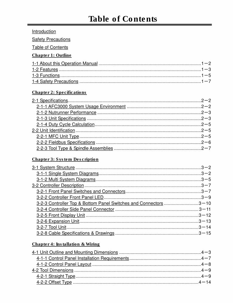
Table of Contents
Introduction
Safety Precautions
Table of Contents
Chapter 1: Outline
1-1 About this Operation Manual ................................................................................ 1-2
1-2 Features ............................................................................................................... 1-3
1-3 Functions .............................................................................................................. 1-5
1-4 Safety Precautions ............................................................................................... 1-7
Chapter 2: Specifications
2-1 Specifications........................................................................................................ 2-2
2-1-1 AFC3000 System Usage Environment .......................................................... 2-2
2-1-2 Nutrunner Performance ................................................................................. 2-3
2-1-3 Unit Specifications ......................................................................................... 2-3
2-1-4 Duty Cycle Calculation ................................................................................... 2-5
2-2 Unit Identification .................................................................................................. 2-5
2-2-1 MFC Unit Type ............................................................................................... 2-5
2-2-2 Fieldbus Specifications .................................................................................. 2-6
2-2-3 Tool Type & Spindle Assemblies .................................................................... 2-7
Chapter 3: System Description
3-1 System Structure .................................................................................................. 3-2
3-1-1 Single System Diagrams................................................................................ 3-2
3-1-2 Multi System Diagrams .................................................................................. 3-5
3-2 Controller Description ........................................................................................... 3-7
3-2-1 Front Panel Switches and Connectors ........................................................... 3-7
3-2-2 Controller Front Panel LED ............................................................................ 3-9
3-2-3 Controller Top & Bottom Panel Switches and Connectors ........................... 3-10
3-2-4 Controller Side Panel Connector ................................................................. 3-11
3-2-5 Front Display Unit ........................................................................................ 3-12
3-2-6 Expansion Unit ............................................................................................. 3-13
3-2-7 Tool Unit ....................................................................................................... 3-14
3-2-8 Cable Specifications & Drawings ................................................................. 3-15
Chapter 4: Installation & Wiring
4-1 Unit Outline and Mounting Dimensions ................................................................ 4-3
4-1-1 Control Panel Installation Requirements ........................................................ 4-7
4-1-2 Control Panel Layout ..................................................................................... 4-8
4-2 Tool Dimensions ................................................................................................... 4-9
4-2-1 Straight Type .................................................................................................. 4-9
4-2-2 Offset Type .................................................................................................. 4-14
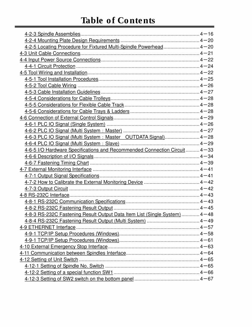
Table of Contents
4-2-3 Spindle Assemblies...................................................................................... 4-16
4-2-4 Mounting Plate Design Requirements ......................................................... 4-20
4-2-5 Locating Procedure for Fixtured Multi-Spindle Powerhead .......................... 4-20
4-3 Unit Cable Connections ...................................................................................... 4-21
4-4 Input Power Source Connections ....................................................................... 4-22
4-4-1 Circuit Protection ......................................................................................... 4-24
4-5 Tool Wiring and Installation................................................................................. 4-22
4-5-1 Tool Installation Procedures ......................................................................... 4-25
4-5-2 Tool Cable Wiring ........................................................................................ 4-26
4-5-3 Cable Installation Guidelines ....................................................................... 4-27
4-5-4 Considerations for Cable Trolleys ................................................................ 4-28
4-5-5 Considerations for Flexible Cable Track ...................................................... 4-28
4-5-6 Considerations for Cable Trays & Ladders .................................................. 4-28
4-6 Connection of External Control Signals .............................................................. 4-29
4-6-1 PLC IO Signal (Single System) ................................................................... 4-26
4-6-2 PLC IO Signal (Multi System:Master) ....................................................... 4-27
4-6-3 PLC IO Signal (Multi System:Master OUTDATA Signal) ......................... 4-28
4-6-4 PLC IO Signal (Multi System:Slave) ......................................................... 4-29
4-6-5 I/O Hardware Specifications and Recommended Connection Circuit .......... 4-33
4-6-6 Description of I/O Signals ............................................................................ 4-34
4-6-7 Fastening Timing Chart ............................................................................... 4-39
4-7 External Monitoring Interface ............................................................................. 4-41
4-7-1 Output Signal Specifications ........................................................................ 4-41
4-7-2 How to Calibrate the External Monitoring Device ........................................ 4-42
4-7-3 Output Circuit .............................................................................................. 4-42
4-8 RS-232C Interface.............................................................................................. 4-43
4-8-1 RS-232C Communication Specifications ..................................................... 4-43
4-8-2 RS-232C Fastening Result Output .............................................................. 4-45
4-8-3 RS-232C Fastening Result Output Data Item List (Single System) ............. 4-48
4-8-4 RS-232C Fastening Result Output (Multi System) ...................................... 4-49
4-9 ETHERNET Interface ......................................................................................... 4-57
4-9-1 TCP/IP Setup Procedures (Windows).......................................................... 4-58
4-9-1 TCP/IP Setup Procedures (Windows).......................................................... 4-61
4-10 External Emergency Stop Interface .................................................................. 4-63
4-11 Communication between Spindles Interface ..................................................... 4-64
4-12 Setting of Unit Switch ....................................................................................... 4-65
4-12-1 Setting of Spindle No. Switch .................................................................... 4-65
4-12-2 Setting of a special function SW1 .............................................................. 4-66
4-12-3 Setting of SW2 switch on the bottom panel ............................................... 4-67
Table of Contents
Chapter 5: Expansion Units
5-1 Expansion Units .................................................................................................... 5-2
5-2 List of External Control Interfaces ......................................................................... 5-2
5-3 Expansion I/O – 24VDC Discrete I/O .................................................................... 5-3
5-3-1 Description of Hardware ................................................................................ 5-3
5-3-2 I/O Signal Specifications ................................................................................ 5-4
5-3-3 I/O Signal Descriprions .................................................................................. 5-8
5-3-4 PLC Output Layout ...................................................................................... 5-11
5-3-5 Description of Output Signals ...................................................................... 5-13
5-3-6 I/O Hardware Specifications and Recommended Connection Circuit .......... 5-18
5-3-7 Signal Timing Chart ..................................................................................... 5-19
5-4 Compact Flash ................................................................................................... 5-22
5-4-1 Using the (CF) Memory Card ....................................................................... 5-23
5-4-2 Data Storage File Format ............................................................................. 5-24
5-4-3 Formatting the Memory Card ....................................................................... 5-27
5-5 Expansion RS232C Interface ............................................................................. 5-28
5-5-1 ID Data Input Setting.................................................................................... 5-29
Chapter 6: Operational Tests
6-1 Power Activation・Operational Test ..................................................................... 6-2
6-1-1 Before Powering On ...................................................................................... 6-2
6-1-2 Items to be checked when the power is turned on ......................................... 6-3
6-1-3 Initial Data Setting .......................................................................................... 6-4
Chapter 7: Fastening Instructions
7-1 Fastening Settings Outline ................................................................................... 7-2
7-2 Fastening Methods ............................................................................................... 7-3
7-2-1 Torque Control Method (Angle Monitoring) .................................................... 7-3
7-2-2 Angle Control Medhod (Torque Monitoring) ................................................. 7-10
7-2-3 Fastening Option [Data No. 002] ................................................................. 7-17
7-2-4 Operation After Fastening [Data No. 006] .................................................... 7-22
7-2-5 Offset Check Function ................................................................................. 7-24
7-3 Judgment Functions ........................................................................................... 7-25
7-3-1 Torque / Angle Judgment ............................................................................. 7-26
7-3-2 Torque Rate Check ...................................................................................... 7-32
7-3-3 DIfferential Angle Check .............................................................................. 7-35
7-3-4 Torque Inhibit Check .................................................................................... 7-36
7-3-5 Breakaway Torque Check ............................................................................ 7-36
7-3-6 Current Value Warnings ............................................................................... 7-37
7-3-7 Step Missed Reject ...................................................................................... 7-38
7-4 Fastening Speed and Time ................................................................................. 7-39
Table of Contents
Chapter 8: System Operation
8-1 Controller Display Device ..................................................................................... 8-2
8-2 RUN/BYPASS Switch ........................................................................................... 8-5
8-3 RUN State ............................................................................................................ 8-6
8-3-1 RUN State Mode Selection ............................................................................ 8-7
8-3-2 REAL TIME Display Mode (Real Time Mode) ................................................ 8-8
8-3-3 RUN Mode Display (Fastening Result Display Mode) ................................. 8-11
8-3-4 RUN Mode Display (Fastening Parameter Display Mode) ........................... 8-14
8-3-5 RUN Mode Display (System Parameter Display Mode) .............................. 8-15
8-3-6 RUN Mode Display (Fastening Status Display) ........................................... 8-16
8-4 BYPASS State .................................................................................................... 8-19
8-4-1 BYPASS State Mode Selection .................................................................... 8-20
8-4-2 BYPASS Mode Display (Parameter Selection Mode) .................................. 8-21
8-4-3 BYPASS Mode Display (Parameter Edit Mode) ........................................... 8-22
8-5 System Mode Change Over – Multi / Single System .......................................... 8-24
8-5-1 Multi System → Single System.................................................................... 8-24
8-5-2 Single System → Multi System.................................................................... 8-25
8-6 Parameter Copy / Erase the Fastening Results History ..................................... 8-26
8-7 Parameter Structure ........................................................................................... 8-29
8-7-1 Parameter Lists ........................................................................................... 8-30
8-7-2 System Parameter ....................................................................................... 8-34
8-7-3 Fastening Parameter (Fastening Setting) .................................................... 8-45
8-7-4 Fastening Parameter (Torque) ..................................................................... 8-49
8-7-5 Fastening Parameter (Angle) ...................................................................... 8-52
8-7-6 Fastening Parameter (Rate / Time) ............................................................. 8-55
8-7-7 Fastening Parameter (Speed) ..................................................................... 8-57
8-7-8 Fastening Parameter (Revolutions / Number of Rotations / Current) .......... 8-59
Chapter 9: Maintenance & Inspection
9-1 Inspection Items ................................................................................................... 9-2
9-1-1 Tools (Motors) ................................................................................................ 9-2
9-1-2 Cables ........................................................................................................... 9-2
9-1-3 Spindle Assembly .......................................................................................... 9-2
9-1-4 Controller (MFC) ............................................................................................ 9-3
9-1-5 Transmission Disassembly and Inspection .................................................... 9-3
9-2 Basic Operational Tests ........................................................................................ 9-5
9-2-1 Torque Transducer ......................................................................................... 9-5
9-2-2 Resolver ........................................................................................................ 9-6
9-2-3 Motor ............................................................................................................. 9-6
9-3 Replacement ........................................................................................................ 9-7
9-3-1 MFC Unit ....................................................................................................... 9-7
9-3-2 Tool ................................................................................................................ 9-8
Table of Contents
Chapter 10: Troubleshooting
10-1 Abnormal Condition Display ……………………………………………………….. 10-2
10-2 [A.01]: Torque Transducer Errors ………………….. .......................................... 10-3
10-3 [A.03]: Preamplifier Errors …………………………………………………………. 10-7
10-4 [A.04]: System Memory Errors ……………………………………………………. 10-8
10-5 [A.05]: Servo Amplifier Reply Errors ………………………………………… ..... 10-10
10-6 [A.06]: Servo Amplifier Type Errors ……………………………………………10-11
10-7 [A.08]: Servo Amplifier Errors …………………………………………………… . 10-12
10-8 [A.09]: Parameter Errors ……………………………………………………… .. 10-16
10-9 [A.10]: Multi Signal Errors……………………………………………………….. .. 10-17
10-10 Spindle Judgment: Checking The Reason For a Reject………………. ......... 10-20
10-11 Ethernet Communication………………. ........................................................ 10-22
10-11-1 Check Windows Firewall ………………………………………………… ... 10-23
10-11-2 Confirmation Connection by Using the Command Prompt ................... 10-25
10-12 RTC (Real Time Clock)………………………………………………................. 10-27

Chapter 1 Outline
PAGE 1-1
Chapter 1: Outline
1
Chapter 1 Outline
PAGE 1-2
1-1 About this Operation Manual
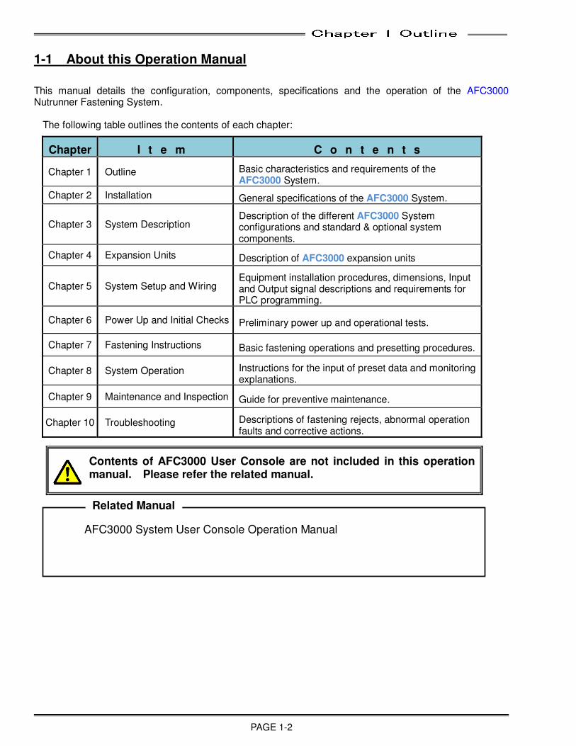
This manual details the configuration, components, specifications and the operation of the AFC3000 Nutrunner Fastening System.
The following table outlines the contents of each chapter:
Chapter I t e m C o n t e n t s
Chapter 1 Outline Basic characteristics and requirements of the AFC3000 System.
Chapter 2 Installation General specifications of the AFC3000 System.
Chapter 3 System Description Description of the different AFC3000 System configurations and standard & optional system components.
Chapter 4 Expansion Units Description of AFC3000 expansion units
Chapter 5 System Setup and Wiring Equipment installation procedures, dimensions, Input and Output signal descriptions and requirements for PLC programming.
Chapter 6 Power Up and Initial Checks Preliminary power up and operational tests.
Chapter 7 Fastening Instructions Basic fastening operations and presetting procedures.
Chapter 8 System Operation Instructions for the input of preset data and monitoring explanations.
Chapter 9 Maintenance and Inspection Guide for preventive maintenance.
Chapter 10 Troubleshooting Descriptions of fastening rejects, abnormal operation faults and corrective actions.
Contents of AFC3000 User Console are not included in this operation manual. Please refer the related manual.
AFC3000 System User Console Operation Manual Related Manual

Chapter 1 Outline
PAGE 1-3
1-2 Features
The AFC3000 System is our newest fastening system developed with the goal of making the AFC1500 Nutrunner System simpler and more flexible. The Multi unit functions are incorporated in the conventional Axis (Spindle) Controller, eliminating the need for the extra controller. The multi-spindle system control and external communication functions have been enhanced to realize a fastening system capable of adapting flexibility to the ever-evolving production facilities of the future.
☆☆☆☆ Reduced set up time
The addition of the Multi function into each spindle allows individual control of the fastening sequencing eliminating the need for external control devices (PLC) to perform complicated spindle control sequencing. This feature allows the MFC Unit to control a variety of complex sequencing strategies including; incremental fastening steps, reject (reverse) strategies, joint conditioning, wait timing, etc. internally within our controller, eliminating the need for complicated PLC logic code. Also available are sequence Input / Output interfaces which allow external control of sequence starting / stopping with outside automation while in sequence. The fastening sequence is able to be input using simple, straightforward commands and does not require specialized knowledge to program a sequence. ☆☆☆☆ Simple setting changes
Fastening parameters, fastening sequences and other various settings process can be easily implemented by the AFC3000 User Console.
☆☆☆☆ Simplified wiring
In a multi-spindle configuration, the Master unit assumes control of the control signals (Ex.: STOP, START, REVERSE, BYPASS, etc.) to all of the Controllers connected to it (up to 32 spindles) via the high speed communication port, thus eliminating direct connection & control to the individual spindles saving costly I/O connection.
☆☆☆☆ EEEExternal control interfaces (Fieldbus)
By using a Fieldbus expansion unit, a variety of Fieldbus interfaces are available for I/O as well as fastening data messaging (Data messaging available in certain Fieldbus interfaces). All of the Input/Output for controlling signals between the station PLC and the system are able to be controlled over one convienent connection.
☆☆☆☆ On-board fastening curve and cycle data storage
The MFC Unit stores the previous 100 fastening curves (waveforms) (from ending point of fastening to the last 540 deg after fastening begins) along with the previous 12,000 fastening result data in RAM (non-volatile) available for uploading. For a multi spindle system, the number of cycles stored is based on the number of spindles connected and the fastening method used. The data can be uploaded, viewed and saved to file using the AFC3000 User Console software package.
☆☆☆☆ Fastening data can be saved to Compact Flash (CF) Card
The fastening results and fastening curves can be saved to the Compact Flash Card when using the CF expansion unit. Data storage capacity differs according to the number of connected spindles, fastening method, etc. and is based on the size of the compact Flash memory card that is installed and also by the number of connected spindles or the fastening method used. [Max. 8GB using FAT32 format] (Approximately 1.8 million results can be stored for a 1 spindle system and 0.1million results for a 32 spindle system. Additionally, a record of changes to the parameter set values can also be stored.
Chapter 1 Outline
PAGE 1-4
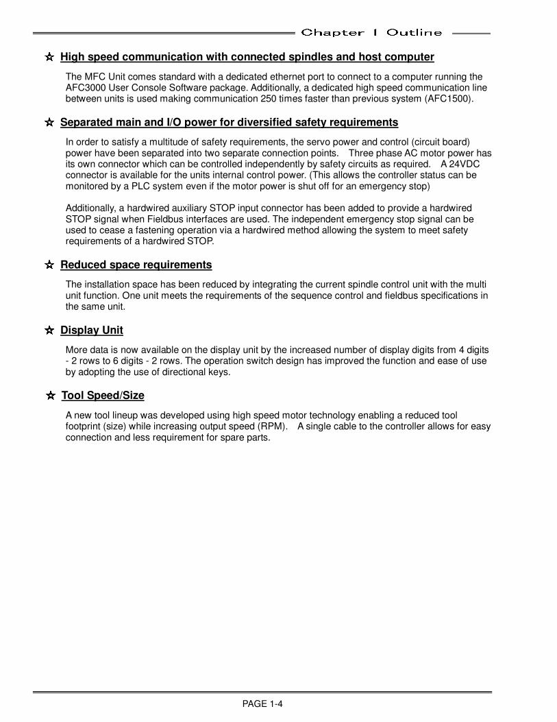
☆☆☆☆ High speed communication with connected spindles and host computer
The MFC Unit comes standard with a dedicated ethernet port to connect to a computer running the AFC3000 User Console Software package. Additionally, a dedicated high speed communication line between units is used making communication 250 times faster than previous system (AFC1500).
☆☆☆☆ Separated main and I/O power for diversified safety requirements
In order to satisfy a multitude of safety requirements, the servo power and control (circuit board) power have been separated into two separate connection points. Three phase AC motor power has its own connector which can be controlled independently by safety circuits as required. A 24VDC connector is available for the units internal control power. (This allows the controller status can be monitored by a PLC system even if the motor power is shut off for an emergency stop) Additionally, a hardwired auxiliary STOP input connector has been added to provide a hardwired STOP signal when Fieldbus interfaces are used. The independent emergency stop signal can be used to cease a fastening operation via a hardwired method allowing the system to meet safety requirements of a hardwired STOP.
☆☆☆☆ Reduced space requirements
The installation space has been reduced by integrating the current spindle control unit with the multi unit function. One unit meets the requirements of the sequence control and fieldbus specifications in the same unit.
☆☆☆☆ Display Unit
More data is now available on the display unit by the increased number of display digits from 4 digits - 2 rows to 6 digits - 2 rows. The operation switch design has improved the function and ease of use by adopting the use of directional keys. ☆☆☆☆ Tool Speed/Size
A new tool lineup was developed using high speed motor technology enabling a reduced tool footprint (size) while increasing output speed (RPM). A single cable to the controller allows for easy connection and less requirement for spare parts.
Chapter 1 Outline
PAGE 1-5
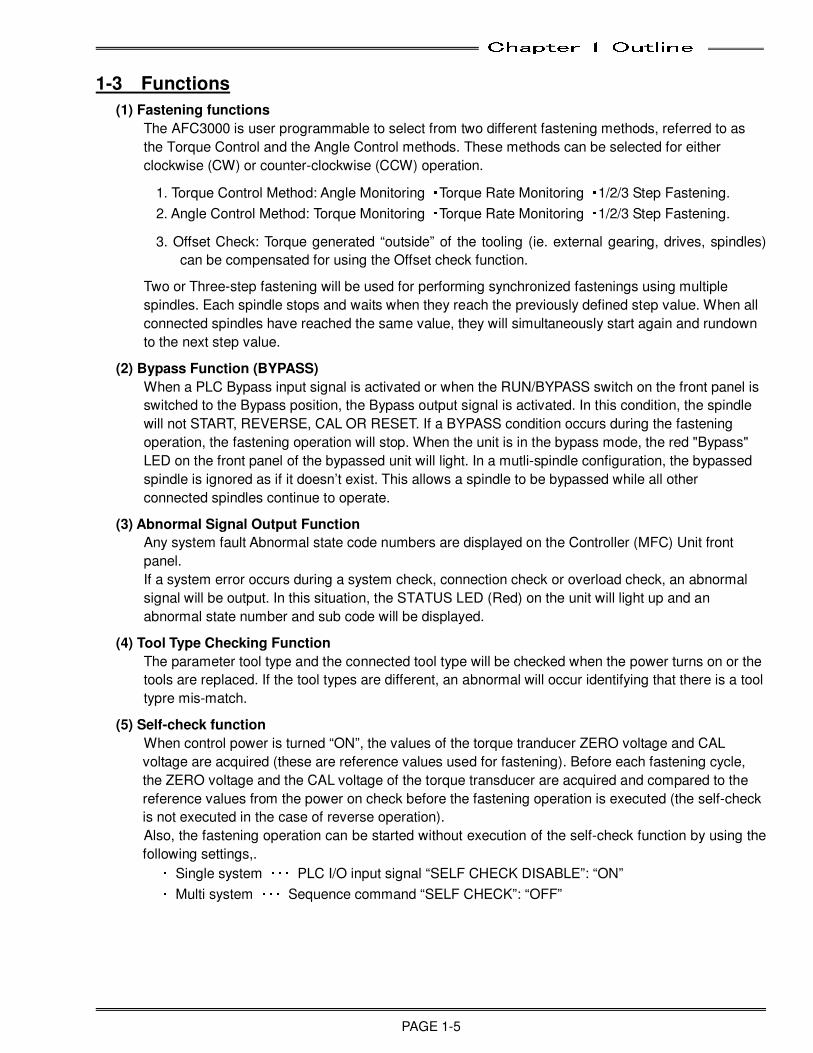
1-3 Functions
(1) Fastening functions
The AFC3000 is user programmable to select from two different fastening methods, referred to as
the Torque Control and the Angle Control methods. These methods can be selected for either
clockwise (CW) or counter-clockwise (CCW) operation.
1. Torque Control Method: Angle Monitoring ・Torque Rate Monitoring ・1/2/3 Step Fastening.
2. Angle Control Method: Torque Monitoring ・Torque Rate Monitoring ・1/2/3 Step Fastening.
3. Offset Check: Torque generated “outside” of the tooling (ie. external gearing, drives, spindles)
can be compensated for using the Offset check function.
Two or Three-step fastening will be used for performing synchronized fastenings using multiple
spindles. Each spindle stops and waits when they reach the previously defined step value. When all
connected spindles have reached the same value, they will simultaneously start again and rundown
to the next step value.
(2) Bypass Function (BYPASS)
When a PLC Bypass input signal is activated or when the RUN/BYPASS switch on the front panel is
switched to the Bypass position, the Bypass output signal is activated. In this condition, the spindle
will not START, REVERSE, CAL OR RESET. If a BYPASS condition occurs during the fastening
operation, the fastening operation will stop. When the unit is in the bypass mode, the red "Bypass"
LED on the front panel of the bypassed unit will light. In a mutli-spindle configuration, the bypassed
spindle is ignored as if it doesn’t exist. This allows a spindle to be bypassed while all other
connected spindles continue to operate.
(3) Abnormal Signal Output Function
Any system fault Abnormal state code numbers are displayed on the Controller (MFC) Unit front
panel.
If a system error occurs during a system check, connection check or overload check, an abnormal
signal will be output. In this situation, the STATUS LED (Red) on the unit will light up and an
abnormal state number and sub code will be displayed.
(4) Tool Type Checking Function
The parameter tool type and the connected tool type will be checked when the power turns on or the
tools are replaced. If the tool types are different, an abnormal will occur identifying that there is a tool
typre mis-match.
(5) Self-check function
When control power is turned “ON”, the values of the torque tranducer ZERO voltage and CAL
voltage are acquired (these are reference values used for fastening). Before each fastening cycle,
the ZERO voltage and the CAL voltage of the torque transducer are acquired and compared to the
reference values from the power on check before the fastening operation is executed (the self-check
is not executed in the case of reverse operation).
Also, the fastening operation can be started without execution of the self-check function by using the
following settings,. ・ Single system ・・・ PLC I/O input signal “SELF CHECK DISABLE”: “ON” ・ Multi system ・・・ Sequence command “SELF CHECK”: “OFF”
Chapter 1 Outline
PAGE 1-6
(6) Fastening Torque Curve Display Function
The torque curve of the fastening operation can be displayed and saved using the AFC3000
software. The curve from 1980deg before the end of fastening or the curve from the start of fastening
to 40 seconds from the start can be displayed by the dedicated software.
(7) Reject Storage Function
Up to a maximum of 500 Reject and Abnormal occurance (data) is stored in the controller as a
record each time an error occurs in the system.
(8) Curve Storage Function
The controller stores 100 sets of fastening result curves in two formats (200 curves total). The
AFC3000 User Console is required for retrieving/reading the curves retained in memory. ・ Storage format: Torque-Angle (540deg) ・ Stored contents (curve retention): Data of 100 of the most recent curves.
Data of 100 of the last REJECT , ABNORMAL curves
* The stored contents (curve retention) will be cleared when the control power of the Unit is
turned OFF.
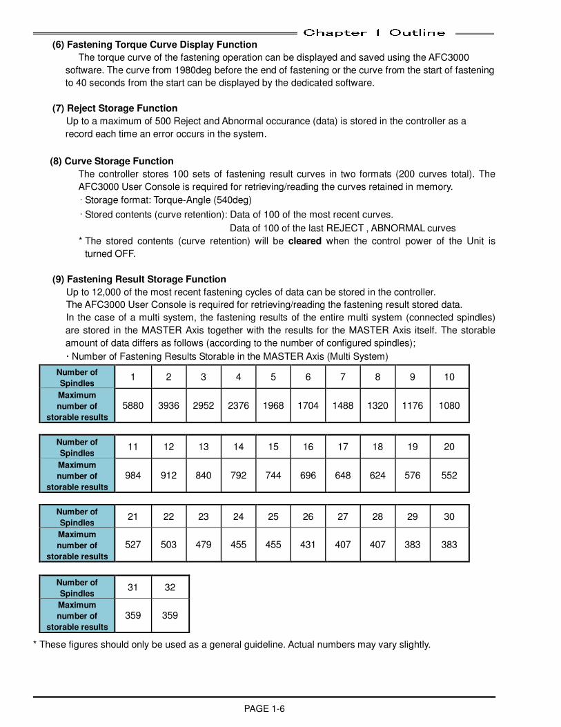
(9) Fastening Result Storage Function
Up to 12,000 of the most recent fastening cycles of data can be stored in the controller.
The AFC3000 User Console is required for retrieving/reading the fastening result stored data.
In the case of a multi system, the fastening results of the entire multi system (connected spindles)
are stored in the MASTER Axis together with the results for the MASTER Axis itself. The storable
amount of data differs as follows (according to the number of configured spindles); ・ Number of Fastening Results Storable in the MASTER Axis (Multi System)
Number of
Spindles 1 2 3 4 5 6 7 8 9 10
Maximum
number of
storable results
5880 3936 2952 2376 1968 1704 1488 1320 1176 1080
Number of
Spindles 11 12 13 14 15 16 17 18 19 20
Maximum
number of
storable results
984 912 840 792 744 696 648 624 576 552
Number of
Spindles 21 22 23 24 25 26 27 28 29 30
Maximum
number of
storable results
527 503 479 455 455 431 407 407 383 383
Number of
Spindles 31 32
Maximum
number of
storable results
359 359
* These figures should only be used as a general guideline. Actual numbers may vary slightly.
Chapter 1 Outline
PAGE 1-7
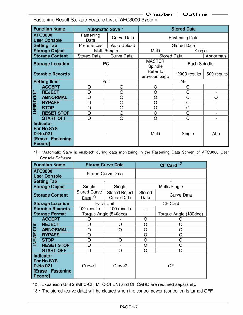
Fastening Result Storage Feature List of AFC3000 System
Function Name Automatic Save *1 Stored Data
AFC3000 User Console
Fastening Data
Curve Data Fastening Data
Setting Tab Preferences Auto Upload Stored Data Storage Object Multi /Single Multi Single Storage Content Stored Data Curve Data Stored Data Abnormals
Storage Location PC MASTER Spindle
Each Spindle
Storable Records - Refer to
previous page 12000 results 500 results
Setting Item Yes No
JU
DG
ME
NT
ACCEPT O O O O - REJECT O O O O - ABNORMAL O O O O O BYPASS O O O O - STOP O O O O - RESET STOP O O O O - START OFF O O O O -
Indicator : Par No.SYS D-No.021 [Erase Fastening Record]
- Multi Single Abn
*1:”Automatic Save is enabled” during data monitoring in the Fastening Data Screen of AFC3000 User
Console Software
Function Name Stored Curve Data CF Card *2
AFC3000 User Console
Stored Curve Data -
Setting Tab - - Storage Object Single Single Multi /Single
Storage Content Stored Curve
Data *3
Stored Reject Curve Data
Stored Data
Curve Data
Storage Location Each Unit CF Card Storable Records 100 results 100 results - - Storage Format Torque-Angle (540deg) - Torque-Angle (180deg)
JU
DG
ME
NT
ACCEPT O - O O REJECT O O O O ABNORMAL O O O O BYPASS O - O O STOP O O O O RESET STOP O - O O START OFF O O O O
Indicator : Par No.SYS D-No.021 [Erase Fastening Record]
Curve1 Curve2 CF
*2:Expansion Unit 2 (MFC-CF, MFC-CFEN) and CF CARD are required separately.
*3:The stored (curve data) will be cleared when the control power (controller) is turned OFF.
Chapter 1 Outline
PAGE 1-8
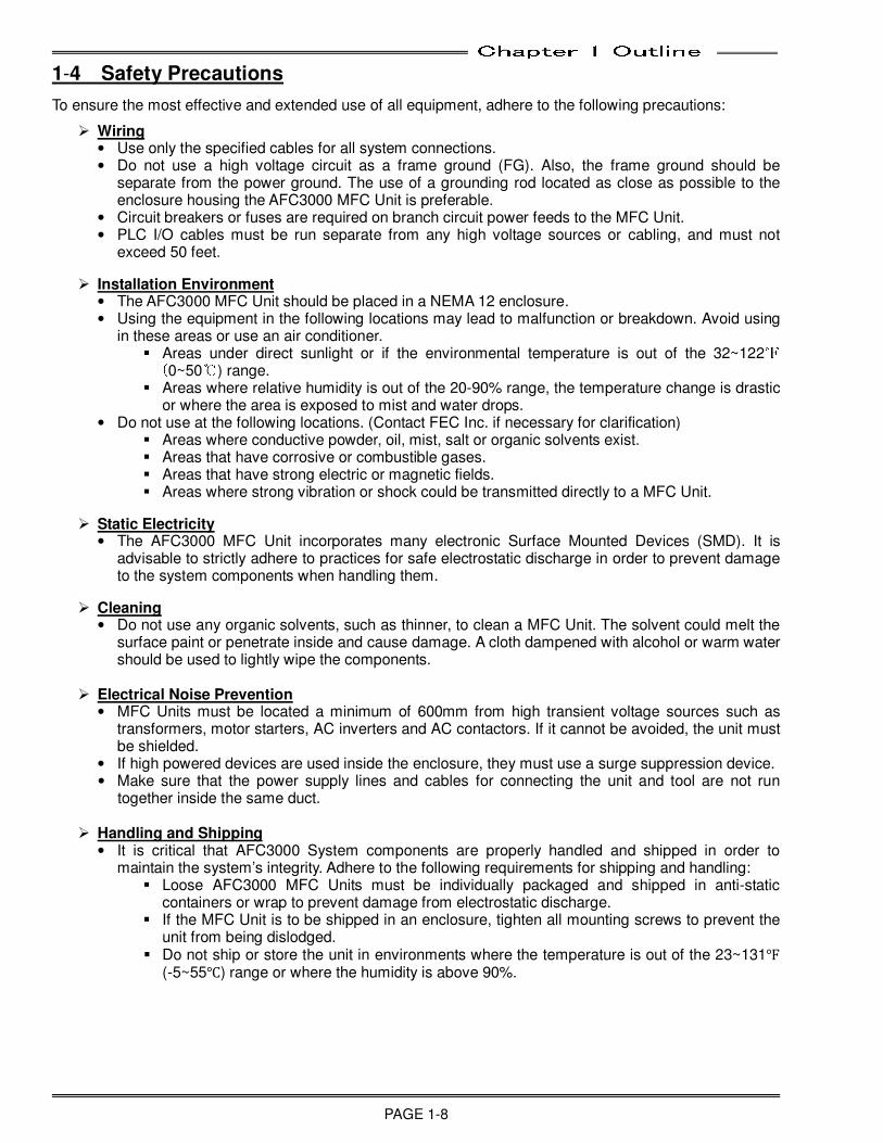
1-4 Safety Precautions
To ensure the most effective and extended use of all equipment, adhere to the following precautions:
Wiring • Use only the specified cables for all system connections. • Do not use a high voltage circuit as a frame ground (FG). Also, the frame ground should be
separate from the power ground. The use of a grounding rod located as close as possible to the enclosure housing the AFC3000 MFC Unit is preferable.
• Circuit breakers or fuses are required on branch circuit power feeds to the MFC Unit. • PLC I/O cables must be run separate from any high voltage sources or cabling, and must not
exceed 50 feet.
Installation Environment • The AFC3000 MFC Unit should be placed in a NEMA 12 enclosure. • Using the equipment in the following locations may lead to malfunction or breakdown. Avoid using
in these areas or use an air conditioner. Areas under direct sunlight or if the environmental temperature is out of the 32~122℉ (0~50℃) range. Areas where relative humidity is out of the 20-90% range, the temperature change is drastic
or where the area is exposed to mist and water drops. • Do not use at the following locations. (Contact FEC Inc. if necessary for clarification)
Areas where conductive powder, oil, mist, salt or organic solvents exist. Areas that have corrosive or combustible gases. Areas that have strong electric or magnetic fields. Areas where strong vibration or shock could be transmitted directly to a MFC Unit.
Static Electricity
• The AFC3000 MFC Unit incorporates many electronic Surface Mounted Devices (SMD). It is advisable to strictly adhere to practices for safe electrostatic discharge in order to prevent damage to the system components when handling them.
Cleaning
• Do not use any organic solvents, such as thinner, to clean a MFC Unit. The solvent could melt the surface paint or penetrate inside and cause damage. A cloth dampened with alcohol or warm water should be used to lightly wipe the components.
Electrical Noise Prevention
• MFC Units must be located a minimum of 600mm from high transient voltage sources such as transformers, motor starters, AC inverters and AC contactors. If it cannot be avoided, the unit must be shielded.
• If high powered devices are used inside the enclosure, they must use a surge suppression device. • Make sure that the power supply lines and cables for connecting the unit and tool are not run
together inside the same duct.
Handling and Shipping • It is critical that AFC3000 System components are properly handled and shipped in order to
maintain the system’s integrity. Adhere to the following requirements for shipping and handling: Loose AFC3000 MFC Units must be individually packaged and shipped in anti-static
containers or wrap to prevent damage from electrostatic discharge. If the MFC Unit is to be shipped in an enclosure, tighten all mounting screws to prevent the
unit from being dislodged. Do not ship or store the unit in environments where the temperature is out of the 23~131℉
(-5~55℃) range or where the humidity is above 90%.

Chapter 2 Specifications
PAGE 2-1
Chapter 2: Specifications
2
Chapter 2 Specifications
PAGE 2-2
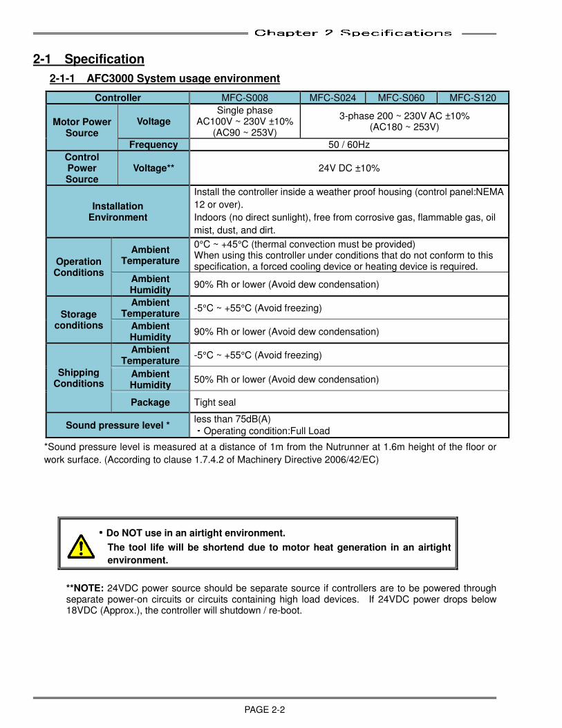
2-1 Specification
2-1-1 AFC3000 System usage environment
Controller MFC-S008 MFC-S024 MFC-S060 MFC-S120
Motor Power Source
Voltage Single phase
AC100V ~ 230V ±10% (AC90 ~ 253V)
3-phase 200 ~ 230V AC ±10% (AC180 ~ 253V)
Frequency 50 / 60Hz
Control Power Source
Voltage** 24V DC ±10%
Installation Environment
Install the controller inside a weather proof housing (control panel:NEMA
12 or over).
Indoors (no direct sunlight), free from corrosive gas, flammable gas, oil
mist, dust, and dirt.
Operation Conditions
Ambient Temperature
0°C ~ +45°C (thermal convection must be provided) When using this controller under conditions that do not conform to this specification, a forced cooling device or heating device is required.
Ambient Humidity
90% Rh or lower (Avoid dew condensation)
Storage conditions
Ambient Temperature
-5°C ~ +55°C (Avoid freezing)
Ambient Humidity
90% Rh or lower (Avoid dew condensation)
Shipping Conditions
Ambient Temperature
-5°C ~ +55°C (Avoid freezing)
Ambient Humidity
50% Rh or lower (Avoid dew condensation)
Package Tight seal
Sound pressure level * less than 75dB(A)
・Operating condition:Full Load
*Sound pressure level is measured at a distance of 1m from the Nutrunner at 1.6m height of the floor or
work surface. (According to clause 1.7.4.2 of Machinery Directive 2006/42/EC)
・・・・Do NOT use in an airtight environment.
The tool life will be shortend due to motor heat generation in an airtight
environment.
**NOTE: 24VDC power source should be separate source if controllers are to be powered through separate power-on circuits or circuits containing high load devices. If 24VDC power drops below 18VDC (Approx.), the controller will shutdown / re-boot.
Chapter 2 Specifications
PAGE 2-3
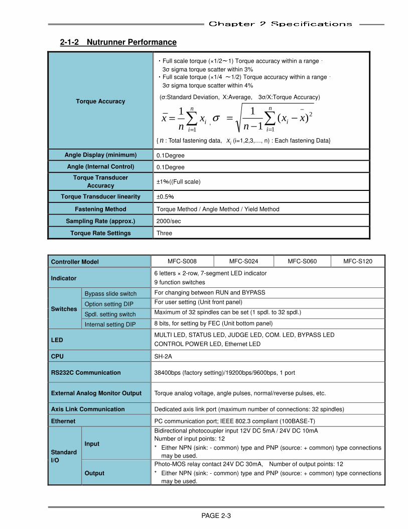
2-1-2 Nutrunner Performance
Torque Accuracy
・Full scale torque (×1/2~1) Torque accuracy within a range:
3σ sigma torque scatter within 3%
・Full scale torque (×1/4 ~1/2) Torque accuracy within a range:
3σ sigma torque scatter within 4%
(σ:Standard Deviation, Χ―
:Average, 3σ/Χ―
:Torque Accuracy)
=
=
n
i
ix
nx
1
1,
2
1
)(1
1
=
−
−
−
=
n
i
ixx
nσ
{ n : Total fastening data, i
x (i=1,2,3,…, n) : Each fastening Data}
Angle Display (minimum) 0.1Degree
Angle (Internal Control) 0.1Degree
Torque Transducer
Accuracy ±1%((Full scale)
Torque Transducer linearity ±0.5%
Fastening Method Torque Method / Angle Method / Yield Method
Sampling Rate (approx.) 2000/sec
Torque Rate Settings Three
Controller Model MFC-S008 MFC-S024 MFC-S060 MFC-S120
Indicator 6 letters × 2-row, 7-segment LED indicator
9 function switches
Switches
Bypass slide switch For changing between RUN and BYPASS
Option setting DIP For user setting (Unit front panel)
Spdl. setting switch Maximum of 32 spindles can be set (1 spdl. to 32 spdl.)
Internal setting DIP 8 bits, for setting by FEC (Unit bottom panel)
LED MULTI LED, STATUS LED, JUDGE LED, COM. LED, BYPASS LED
CONTROL POWER LED, Ethernet LED
CPU SH-2A
RS232C Communication 38400bps (factory setting)/19200bps/9600bps, 1 port
External Analog Monitor Output Torque analog voltage, angle pulses, normal/reverse pulses, etc.
Axis Link Communication Dedicated axis link port (maximum number of connections: 32 spindles)
Ethernet PC communication port; IEEE 802.3 compliant (100BASE-T)
Standard
I/O
Input
Bidirectional photocoupler input 12V DC 5mA / 24V DC 10mA
Number of input points: 12
* Either NPN (sink: - common) type and PNP (source: + common) type connections
may be used.
Output
Photo-MOS relay contact 24V DC 30mA, Number of output points: 12
* Either NPN (sink: - common) type and PNP (source: + common) type connections
may be used.
Chapter 2 Specifications
PAGE 2-4
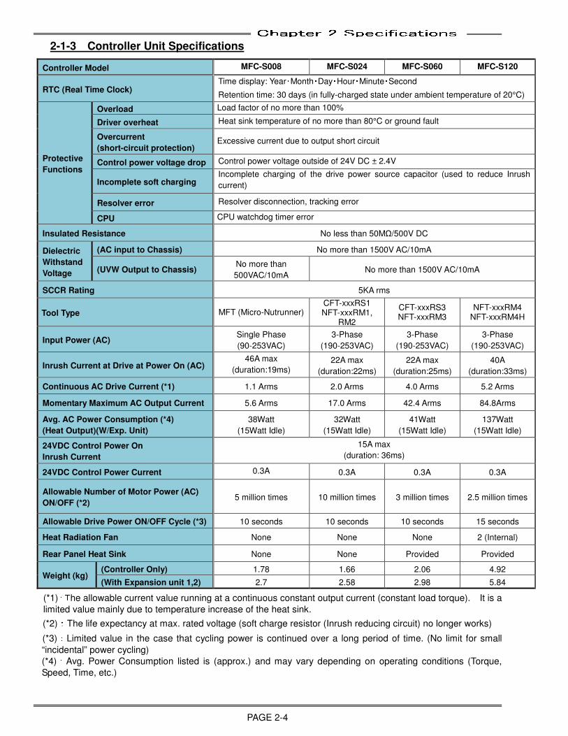
2-1-3 Controller Unit Specifications
Controller Model MFC-S008 MFC-S024 MFC-S060 MFC-S120
RTC (Real Time Clock) Time display: Year・Month・Day・Hour・Minute・Second
Retention time: 30 days (in fully-charged state under ambient temperature of 20°C)
Protective
Functions
Overload Load factor of no more than 100%
Driver overheat Heat sink temperature of no more than 80°C or ground fault
Overcurrent
(short-circuit protection) Excessive current due to output short circuit
Control power voltage drop Control power voltage outside of 24V DC ± 2.4V
Incomplete soft charging Incomplete charging of the drive power source capacitor (used to reduce Inrush
current)
Resolver error Resolver disconnection, tracking error
CPU CPU watchdog timer error
Insulated Resistance No less than 50MΩ/500V DC
Dielectric
Withstand
Voltage
(AC input to Chassis) No more than 1500V AC/10mA
(UVW Output to Chassis) No more than
500VAC/10mA No more than 1500V AC/10mA
SCCR Rating 5KA rms
Tool Type MFT (Micro-Nutrunner) CFT-xxxRS1 NFT-xxxRM1,
RM2
CFT-xxxRS3 NFT-xxxRM3
NFT-xxxRM4 NFT-xxxRM4H
Input Power (AC) Single Phase
(90-253VAC)
3-Phase
(190-253VAC)
3-Phase
(190-253VAC)
3-Phase
(190-253VAC)
Inrush Current at Drive at Power On (AC) 46A max
(duration:19ms) 22A max
(duration:22ms)
22A max
(duration:25ms)
40A
(duration:33ms)
Continuous AC Drive Current (*1) 1.1 Arms 2.0 Arms 4.0 Arms 5.2 Arms
Momentary Maximum AC Output Current 5.6 Arms 17.0 Arms 42.4 Arms 84.8Arms
Avg. AC Power Consumption (*4)
(Heat Output)(W/Exp. Unit)
38Watt
(15Watt Idle)
32Watt
(15Watt Idle)
41Watt
(15Watt Idle)
137Watt
(15Watt Idle)
24VDC Control Power On
Inrush Current
15A max
(duration: 36ms)
24VDC Control Power Current 0.3A 0.3A 0.3A 0.3A
Allowable Number of Motor Power (AC)
ON/OFF (*2) 5 million times 10 million times 3 million times 2.5 million times
Allowable Drive Power ON/OFF Cycle (*3) 10 seconds 10 seconds 10 seconds 15 seconds
Heat Radiation Fan None None None 2 (Internal)
Rear Panel Heat Sink None None Provided Provided
Weight (kg) (Controller Only) 1.78 1.66 2.06 4.92
(With Expansion unit 1,2) 2.7 2.58 2.98 5.84
(*1):The allowable current value running at a continuous constant output current (constant load torque). It is a
limited value mainly due to temperature increase of the heat sink.
(*2):The life expectancy at max. rated voltage (soft charge resistor (Inrush reducing circuit) no longer works)
(*3):Limited value in the case that cycling power is continued over a long period of time. (No limit for small
“incidental” power cycling)
(*4):Avg. Power Consumption listed is (approx.) and may vary depending on operating conditions (Torque,
Speed, Time, etc.)
Chapter 2 Specifications
PAGE 2-5
【
【【
【Caution - Power-On cycle】】】
】
・
・・
・The unit power input circuit is a capacitor input type circuit (soft charge circuit).
A resistor circuit which suppresses inrush current when power is turned on is used (internal voltage reaches a preset standard and then charges through resistance)
・・・
・The resistance of inrush current suppression has a limited cycle life.
Review the power-on cycle referring to the “allowable number of times” the power may be cycled (ON / OFF) listed above.
【
【【
【Warning - Static Electricity】】】
】
・
・・
・Due to the usage of many electronic parts be careful not to expose the controller to static
electricity. Keep in mind to discharge static electricity from the body by touching something metal before touching the controller front panel.
2-1-4 Duty Cycle Calculation
Duty cycle is the ratio of tool fastening (running) time and idle time.
The duty cycle for AFC3000 Nutrunner System is calculated as below.
Duty Cycle(%)=
(%)=(%)=
(%)=
Fastening Time ÷(((
(Fastening Time +++
+ Idle Time)))
)× 100
Maintain the duty cycle less than 60% under normal conditions. An abnormal (A8-10 “Overload Error”) may occur if the unit is used in a condition that the duty cycle is over 60%. (Additional abnormals may also be caused by high duty due to the higher current and heat generated when the motor is ‘overworked’. (Make sure the motor surface temperature does not exceed 70°C (158°F) (Outer Motor Case)). Contact FEC regarding a specified cycle time more than 60% Duty.
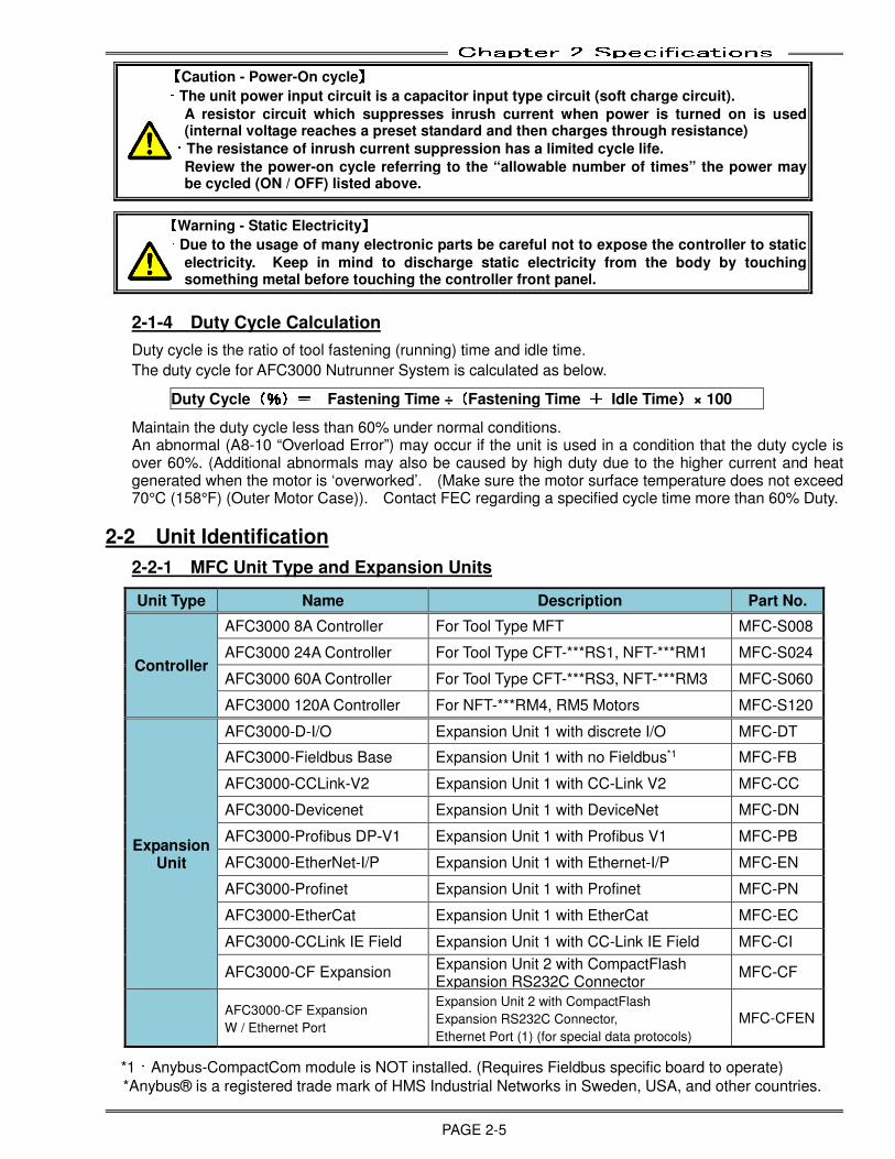
2-2 Unit Identification
2-2-1 MFC Unit Type and Expansion Units
Unit Type Name Description Part No.
Controller
AFC3000 8A Controller For Tool Type MFT MFC-S008
AFC3000 24A Controller For Tool Type CFT-***RS1, NFT-***RM1 MFC-S024
AFC3000 60A Controller For Tool Type CFT-***RS3, NFT-***RM3 MFC-S060
AFC3000 120A Controller For NFT-***RM4, RM5 Motors MFC-S120
Expansion Unit
AFC3000-D-I/O Expansion Unit 1 with discrete I/O MFC-DT
AFC3000-Fieldbus Base Expansion Unit 1 with no Fieldbus*1 MFC-FB
AFC3000-CCLink-V2 Expansion Unit 1 with CC-Link V2 MFC-CC
AFC3000-Devicenet Expansion Unit 1 with DeviceNet MFC-DN
AFC3000-Profibus DP-V1 Expansion Unit 1 with Profibus V1 MFC-PB
AFC3000-EtherNet-I/P Expansion Unit 1 with Ethernet-I/P MFC-EN
AFC3000-Profinet Expansion Unit 1 with Profinet MFC-PN
AFC3000-EtherCat Expansion Unit 1 with EtherCat MFC-EC
AFC3000-CCLink IE Field Expansion Unit 1 with CC-Link IE Field MFC-CI
AFC3000-CF Expansion Expansion Unit 2 with CompactFlash Expansion RS232C Connector
MFC-CF
AFC3000-CF Expansion
W / Ethernet Port
Expansion Unit 2 with CompactFlash
Expansion RS232C Connector,
Ethernet Port (1) (for special data protocols) MFC-CFEN
*1:Anybus-CompactCom module is NOT installed. (Requires Fieldbus specific board to operate)
*Anybus® is a registered trade mark of HMS Industrial Networks in Sweden, USA, and other countries.
Chapter 2 Specifications
PAGE 2-6
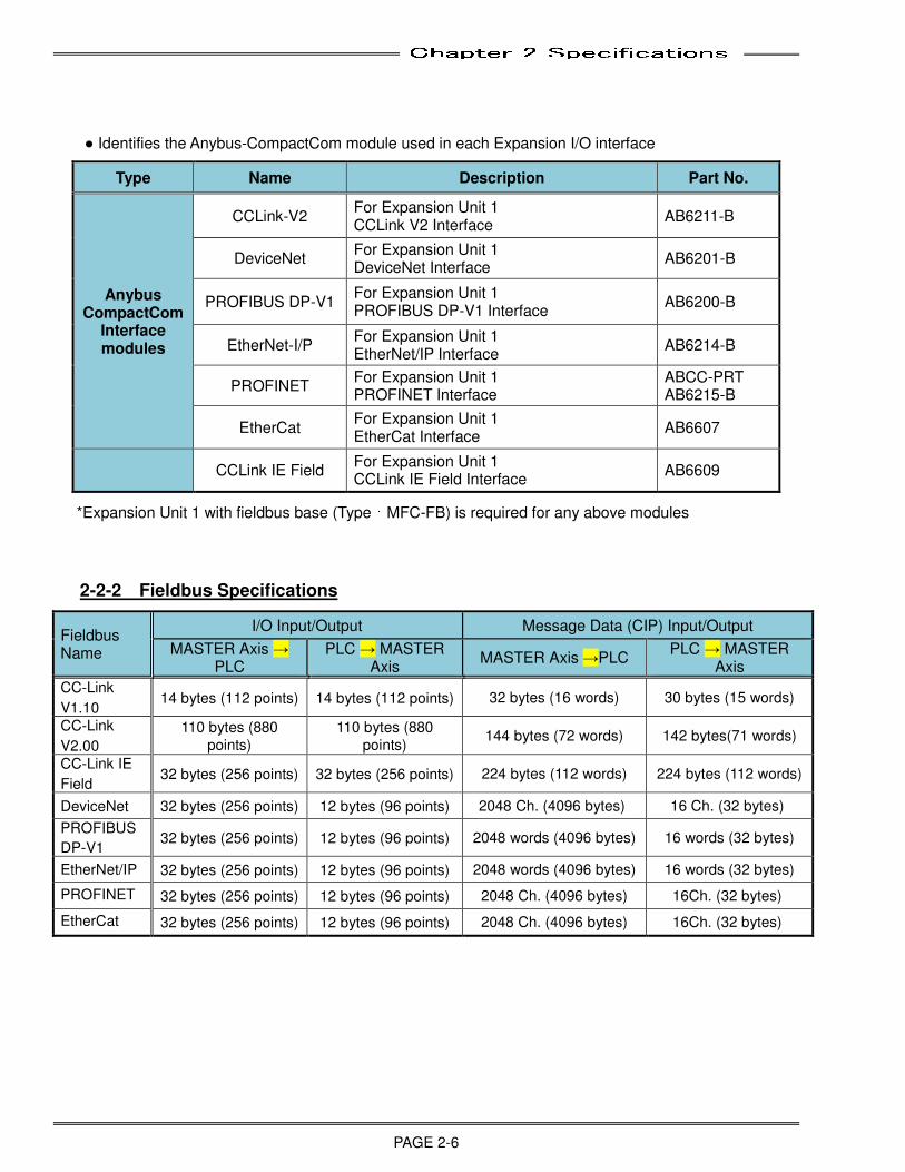
● Identifies the Anybus-CompactCom module used in each Expansion I/O interface
Type Name Description Part No.
Anybus CompactCom
Interface modules
CCLink-V2 For Expansion Unit 1 CCLink V2 Interface
AB6211-B
DeviceNet For Expansion Unit 1 DeviceNet Interface
AB6201-B
PROFIBUS DP-V1 For Expansion Unit 1 PROFIBUS DP-V1 Interface
AB6200-B
EtherNet-I/P For Expansion Unit 1 EtherNet/IP Interface
AB6214-B
PROFINET For Expansion Unit 1 PROFINET Interface
ABCC-PRT AB6215-B
EtherCat For Expansion Unit 1 EtherCat Interface
AB6607
CCLink IE Field For Expansion Unit 1 CCLink IE Field Interface
AB6609
*Expansion Unit 1 with fieldbus base (Type:MFC-FB) is required for any above modules
2-2-2 Fieldbus Specifications
Fieldbus Name
I/O Input/Output Message Data (CIP) Input/Output
MASTER Axis → PLC
PLC → MASTER Axis
MASTER Axis →PLC PLC → MASTER
Axis
CC-Link
V1.10 14 bytes (112 points) 14 bytes (112 points) 32 bytes (16 words) 30 bytes (15 words)
CC-Link
V2.00
110 bytes (880
points)
110 bytes (880
points) 144 bytes (72 words) 142 bytes(71 words)
CC-Link IE
Field 32 bytes (256 points) 32 bytes (256 points) 224 bytes (112 words) 224 bytes (112 words)
DeviceNet 32 bytes (256 points) 12 bytes (96 points) 2048 Ch. (4096 bytes) 16 Ch. (32 bytes)
PROFIBUS
DP-V1 32 bytes (256 points) 12 bytes (96 points) 2048 words (4096 bytes) 16 words (32 bytes)
EtherNet/IP 32 bytes (256 points) 12 bytes (96 points) 2048 words (4096 bytes) 16 words (32 bytes)
PROFINET 32 bytes (256 points) 12 bytes (96 points) 2048 Ch. (4096 bytes) 16Ch. (32 bytes)
EtherCat 32 bytes (256 points) 12 bytes (96 points) 2048 Ch. (4096 bytes) 16Ch. (32 bytes)
Chapter 2 Specifications
PAGE 2-7
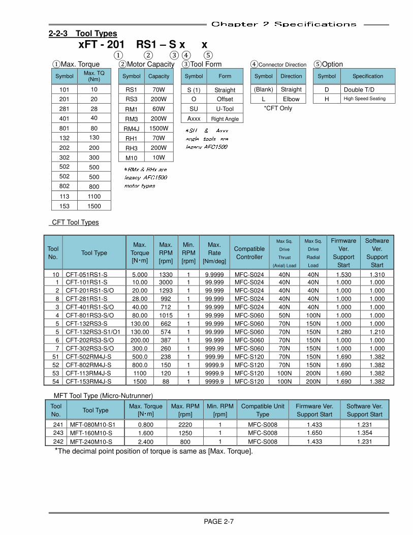
2-2-3 Tool Types
xFT - 201 RS1 – S x x ① ② ③ ④ ⑤
①Max. Torque ②Motor Capacity ③Tool Form ④Connector Direction ⑤Option
Symbol Max. TQ
(Nm)
Symbol Capacity
Symbol Form
Symbol Direction
Symbol Specification
101 10 RS1 70W S (1) Straight (Blank) Straight D Double T/D
201 20 RS3 200W O Offset L Elbow H High Speed Seating
281 28 RM1 60W SU U-Tool *CFT Only
401 40 RM3 200W Axxx Right Angle
801 80 RM4J 1500W
132 130 RH1 70W
202 200 RH3 200W
302 300 M10 10W
502 500
502 500
802 800
113 1100
153 1500
CFT Tool Types
MFT Tool Type (Micro-Nutrunner)
Tool
No. Tool Type
Max. Torque
[N・m]
Max. RPM
[rpm]
Min. RPM
[rpm]
Compatible Unit
Type
Firmware Ver.
Support Start
Software Ver.
Support Start
241 MFT-080M10-S1 0.800 2220 1 MFC-S008 1.433 1.231
243 MFT-160M10-S 1.600 1250 1 MFC-S008 1.650 1.354 242 MFT-240M10-S 2.400 800 1 MFC-S008 1.433 1.231 *The decimal point position of torque is same as [Max. Torque].
Tool
No. Tool Type
Max.
Torque
[N・m]
Max.
RPM
[rpm]
Min.
RPM
[rpm]
Max.
Rate
[Nm/deg]
Compatible
Controller
Max Sq.
Drive
Thrust
(Axial) Load
Max Sq.
Drive
Radial
Load
Firmware
Ver.
Support
Start
Software
Ver.
Support
Start
10 CFT-051RS1-S 5.000 1330 1 9.9999 MFC-S024 40N 40N 1.530 1.310
1 CFT-101RS1-S 10.00 3000 1 99.999 MFC-S024 40N 40N 1.000 1.000 2 CFT-201RS1-S/O 20.00 1293 1 99.999 MFC-S024 40N 40N 1.000 1.000 8 CFT-281RS1-S 28.00 992 1 99.999 MFC-S024 40N 40N 1.000 1.000 3 CFT-401RS1-S/O 40.00 712 1 99.999 MFC-S024 40N 40N 1.000 1.000 4 CFT-801RS3-S/O 80.00 1015 1 99.999 MFC-S060 50N 100N 1.000 1.000 5 CFT-132RS3-S 130.00 662 1 99.999 MFC-S060 70N 150N 1.000 1.000 5 CFT-132RS3-S1/O1 130.00 574 1 99.999 MFC-S060 70N 150N 1.280 1.210 6 CFT-202RS3-S/O 200.00 387 1 99.999 MFC-S060 70N 150N 1.000 1.000 7 CFT-302RS3-S/O 300.0 260 1 999.99 MFC-S060 70N 150N 1.000 1.000
51 CFT-502RM4J-S 500.0 238 1 999.99 MFC-S120 70N 150N 1.690 1.382
52 CFT-802RM4J-S 800.0 150 1 9999.9 MFC-S120 70N 150N 1.690 1.382
53 CFT-113RM4J-S 1100 120 1 9999.9 MFC-S120 100N 200N 1.690 1.382
54 CFT-153RM4J-S 1500 88 1 9999.9 MFC-S120 100N 200N 1.690 1.382
*SU & Axxx
angle tools are
legacy AFC1500
*RMx & RHx are
legacy AFC1500
motor types
Chapter 2 Specifications
PAGE 2-8
NFT Type Tools
Tool
No. Tool Model
Nominal
Torque
[N・m]
Rotation Speed[rpm]
Maximum
Rate
[N・m/deg]
Compatible
Controller
Max Sq.
Drive Thrust
(Axial) Load
Max Sq.
Drive Radial
Load Max Min
126 NFT-010RM1-S 1.00 1100 1 99.999 MFC-S024 20N 40N
127 NFT-051RM1-S 5.00 1100 1 99.999 MFC-S024 20N 40N 125 NFT-051RM1-S1 5.00 500 1 99.999 MFC-S024 20N 40N 128 NFT-101RM1-S 10.00 1100 1 99.999 MFC-S024 20N 40N 129 NFT-101RM1-S1 10.00 500 1 99.999 MFC-S024 20N 40N 130 NFT-201RM1-S 20.00 500 1 99.999 MFC-S024 20N 40N 131 NFT-401RM1-S 40.00 250 1 99.999 MFC-S024 20N 40N 139 NFT-401RM3-S 40.00 790 1 99.999 MFC-S060 50N 100N
183 NFT-401RH3-S 40.00 1984 1 99.999 MFC-S060 50N 100N 140 NFT-601RM3-S 60.00 790 1 99.999 MFC-S060 50N 100N 133 NFT-801RM3-S 80.00 500 1 99.999 MFC-S060 50N 100N 184 NFT-801RH3-S 80.00 1000 1 99.999 MFC-S060 50N 100N 211 NFT-122RH3-S 120.00 1000 1 99.999 MFC-S120 50N 100N 134 NFT-132RM3-S 130.00 395 1 99.999 MFC-S060 50N 100N 186 NFT-132RH3-S 130.00 582 1 99.999 MFC-S060 50N 100N 216 NFT-192RH3-S 194.00 625 1 99.999 MFC-S120 50N 100N 109 NFT-202RM3-S 200.00 220 1 99.999 MFC-S060 50N 100N 187 NFT-202RH3-S 200.00 408 1 99.999 MFC-S060 50N 100N 135 NFT-302RM3-S 300.00 150 1 999.99 MFC-S060 70N 150N
212 NFT-332RH3-S 330.00 385 1 99.999 MFC-S120 70N 150N 100 NFT-502RM4-S 500.0 150 1 999.99 MFC-S120 70N 150N 225 NFT-502RM4HS 500.0 190 1 999.99 MFC-S120 70N 150N 101 NFT-802RM4-S 800.0 90 1 9999.9 MFC-S120 70N 150N 226 NFT-802RM4HS 800.0 120 1 9999.9 MFC-S120 70N 150N 217 NFT-113RM4HS 1100 95 1 9999.9 MFC-S120 70N 150N 218 NFT-153RM4HS 1500 70 1 9999.9 MFC-S120 70N 150N 142 NFT-403RM5-S 4000 39 1 9999.9 MFC-S120 100N 200N
143 NFT-503RM5-S 5000 22 1 9999.9 MFC-S120 100N 200N
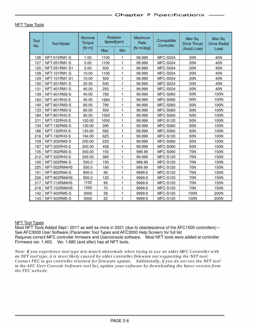
NFT Tool Types Most NFT Tools Added Sept / 2017 as well as more in 2021 (due to obsolescence of the AFC1500 controllers) – See AFC3000 User Software (Parameter Tool Types and AFC3000 Help Screen) for full list Requires correct MFC controller firmware and Userconsole software. Most NFT tools were added at controller Firmware ver. 1.403. Ver. 1.680 (and after) has all NFT tools. Note: If you experience tool type mis-match abnormals when trying to use an older MFC Controller with an NFT tool type, it is most likely caused by older controller firmware not supporting the NFT tool. Contact FEC to get controller returned for firmware update. Additionally, if you do not see the NFT tool in the AFC User Console Software tool list, update your software by downloading the latest version from the FEC website.
Chapter 2 Specifications
PAGE 2-9
● Standard Spindle Assemblies (CFT Tool)
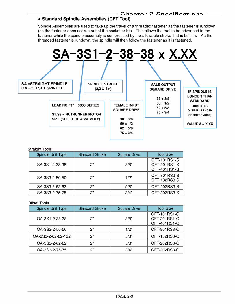
Spindle Assemblies are used to take up the travel of a threaded fastener as the fastener is rundown (so the fastener does not run out of the socket or bit) This allows the tool to be advanced to the fastener while the spindle assembly is compressed by the allowable stroke that is built in. As the threaded fastener is rundown, the spindle will then follow the fastener as it is fastened.
SASASASA----3333S1S1S1S1----2222----38383838----38383838 x x x x X.XXX.XXX.XXX.XX
Straight Tools
Spindle Unit Type Standard Stroke Square Drive Tool Size
SA-3S1-2-38-38 2” 3/8” CFT-101RS1-S CFT-201RS1-S CFT-401RS1-S
SA-3S3-2-50-50 2” 1/2” CFT-801RS3-S CFT-132RS3-S
SA-3S3-2-62-62 2” 5/8” CFT-202RS3-S
SA-3S3-2-75-75 2” 3/4" CFT-302RS3-S
Offset Tools
Spindle Unit Type Standard Stroke Square Drive Tool Size
OA-3S1-2-38-38 2” 3/8” CFT-101RS1-O CFT-201RS1-O CFT-401RS1-O
OA-3S3-2-50-50 2” 1/2” CFT-801RS3-O
OA-3S3-2-62-62-132 2” 5/8” CFT-132RS3-O
OA-3S3-2-62-62 2” 5/8” CFT-202RS3-O
OA-3S3-2-75-75 2” 3/4" CFT-302RS3-O
IF SPINDLE IS
LONGER THAN
STANDARD
(INDICATES
OVERALL LENGTH
OF ROTOR ASSY)
VALUE A = X.XX
MALE OUTPUT
SQUARE DRIVE
38 = 3/8
50 = 1/2
62 = 5/8
75 = 3/4
FEMALE INPUT
SQUARE DRIVE
38 = 3/8
50 = 1/2
62 = 5/8
75 = 3/4
SPINDLE STROKE
(2,3 & 4in)
LEADING “3” = 3000 SERIES
S1,S3 = NUTRUNNER MOTOR
SIZE (SEE TOOL ASSEMBLY)
SA =STRAIGHT SPINDLE OA =OFFSET SPINDLE

Chapter 2 Specifications
PAGE 2-10
(Blank Page)
Chapter 3 System Description
PAGE 3-1
Chapter 3: System Description
3
Chapter 3 System Description
PAGE 3-2
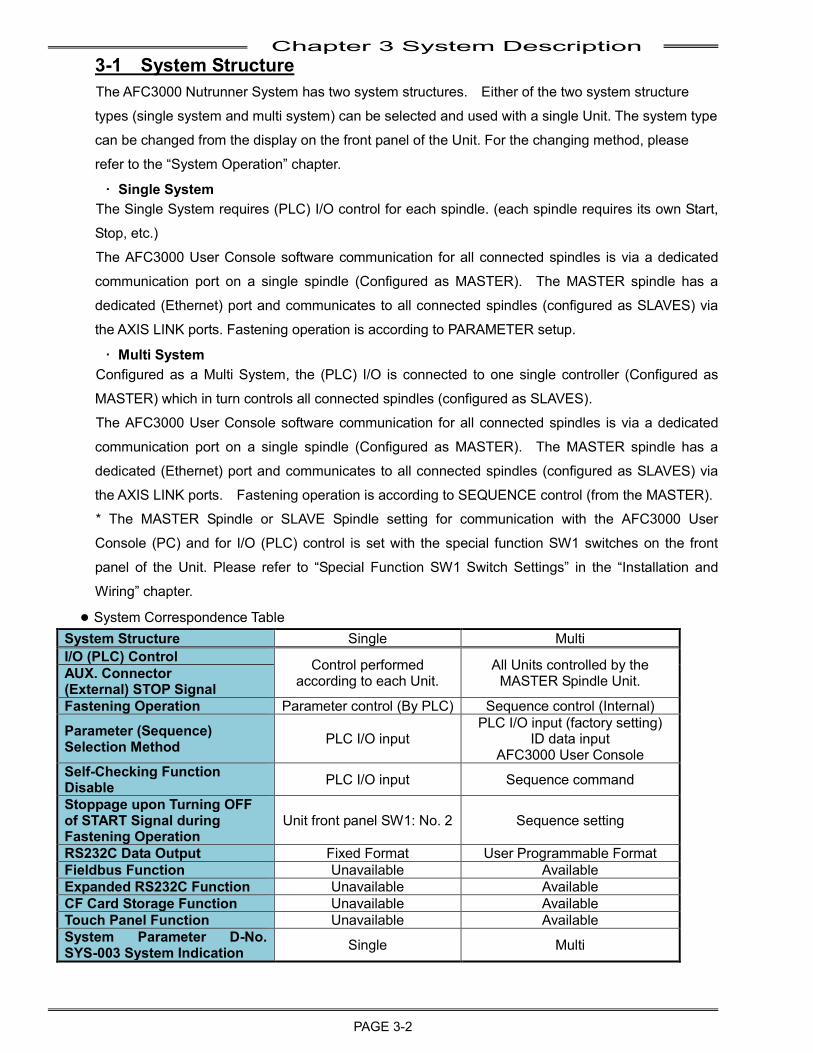
3-1 System Structure The AFC3000 Nutrunner System has two system structures. Either of the two system structure
types (single system and multi system) can be selected and used with a single Unit. The system type
can be changed from the display on the front panel of the Unit. For the changing method, please
refer to the “System Operation” chapter.
・ Single System The Single System requires (PLC) I/O control for each spindle. (each spindle requires its own Start,
Stop, etc.)
The AFC3000 User Console software communication for all connected spindles is via a dedicated
communication port on a single spindle (Configured as MASTER). The MASTER spindle has a
dedicated (Ethernet) port and communicates to all connected spindles (configured as SLAVES) via
the AXIS LINK ports. Fastening operation is according to PARAMETER setup.
・ Multi System Configured as a Multi System, the (PLC) I/O is connected to one single controller (Configured as
MASTER) which in turn controls all connected spindles (configured as SLAVES).
The AFC3000 User Console software communication for all connected spindles is via a dedicated
communication port on a single spindle (Configured as MASTER). The MASTER spindle has a
dedicated (Ethernet) port and communicates to all connected spindles (configured as SLAVES) via
the AXIS LINK ports. Fastening operation is according to SEQUENCE control (from the MASTER). * The MASTER Spindle or SLAVE Spindle setting for communication with the AFC3000 User
Console (PC) and for I/O (PLC) control is set with the special function SW1 switches on the front
panel of the Unit. Please refer to “Special Function SW1 Switch Settings” in the “Installation and
Wiring” chapter.
● System Correspondence Table System Structure Single Multi I/O (PLC) Control Control performed
according to each Unit. All Units controlled by the
MASTER Spindle Unit. AUX. Connector (External) STOP Signal Fastening Operation Parameter control (By PLC) Sequence control (Internal)
Parameter (Sequence) Selection Method PLC I/O input
PLC I/O input (factory setting) ID data input
AFC3000 User Console Self-Checking Function Disable PLC I/O input Sequence command
Stoppage upon Turning OFF of START Signal during Fastening Operation
Unit front panel SW1: No. 2 Sequence setting
RS232C Data Output Fixed Format User Programmable Format Fieldbus Function Unavailable Available Expanded RS232C Function Unavailable Available CF Card Storage Function Unavailable Available Touch Panel Function Unavailable Available System Parameter D-No. SYS-003 System Indication Single Multi
Chapter 3 System Description
PAGE 3-3
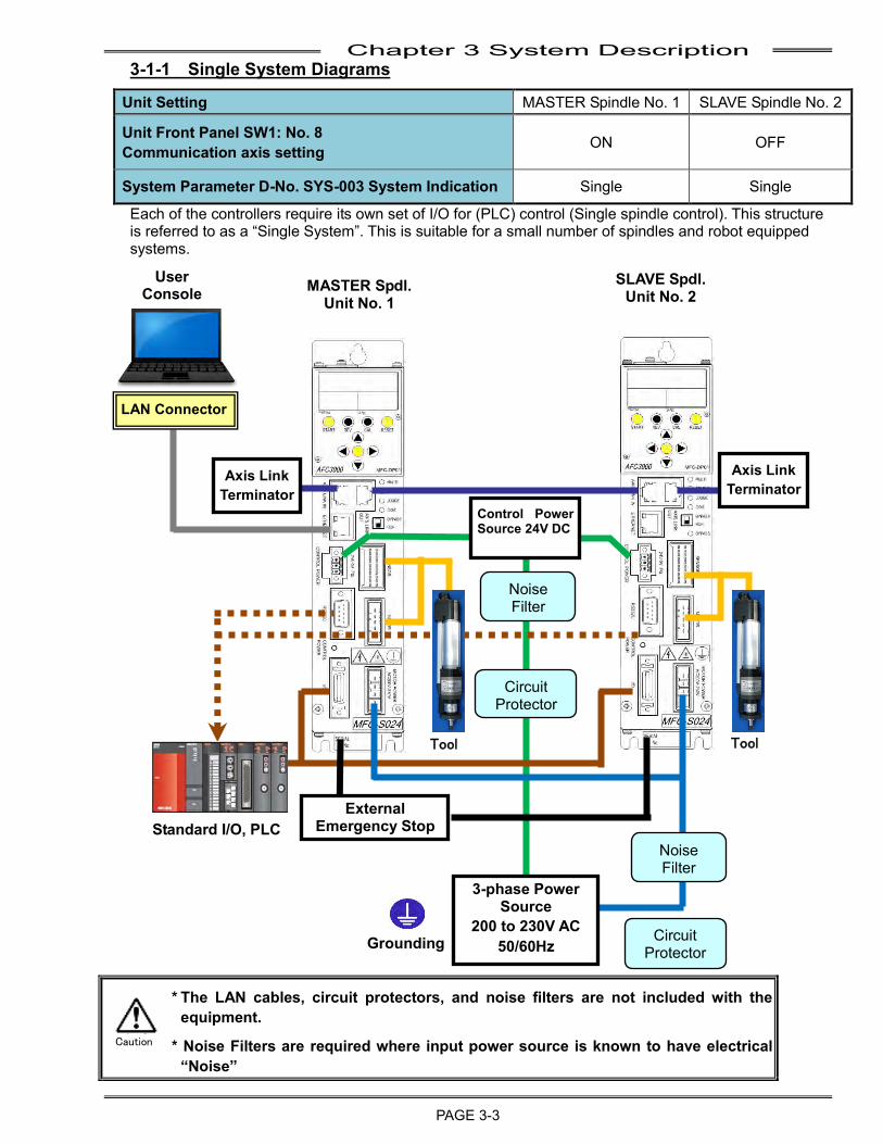
3-1-1 Single System Diagrams
Unit Setting MASTER Spindle No. 1 SLAVE Spindle No. 2
Unit Front Panel SW1: No. 8 Communication axis setting ON OFF
System Parameter D-No. SYS-003 System Indication Single Single
Each of the controllers require its own set of I/O for (PLC) control (Single spindle control). This structure is referred to as a “Single System”. This is suitable for a small number of spindles and robot equipped systems.
* The LAN cables, circuit protectors, and noise filters are not included with the equipment.
* Noise Filters are required where input power source is known to have electrical “Noise”
Tool
External Emergency Stop
Tool
Axis Link Terminator
LAN Connector
Noise Filter
3-phase Power Source
200 to 230V AC 50/60Hz
Noise Filter
Circuit Protector
Grounding
Control Power Source 24V DC
Circuit Protector
Axis Link Terminator
Standard I/O, PLC
User Console
MASTER Spdl. Unit No. 1
SLAVE Spdl. Unit No. 2
Caution
Chapter 3 System Description
PAGE 3-4
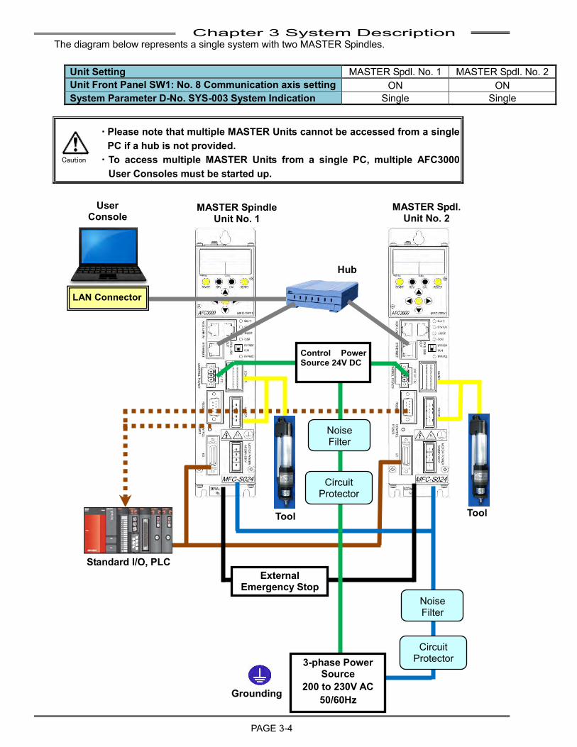
The diagram below represents a single system with two MASTER Spindles.
Unit Setting MASTER Spdl. No. 1 MASTER Spdl. No. 2 Unit Front Panel SW1: No. 8 Communication axis setting ON ON System Parameter D-No. SYS-003 System Indication Single Single
・ Please note that multiple MASTER Units cannot be accessed from a single PC if a hub is not provided.
・ To access multiple MASTER Units from a single PC, multiple AFC3000 User Consoles must be started up.
Tool Tool
Hub
User Console
MASTER Spindle Unit No. 1
MASTER Spdl. Unit No. 2
Control Power Source 24V DC
Circuit Protector
Circuit Protector
Noise Filter
Noise Filter
External Emergency Stop
3-phase Power Source
200 to 230V AC 50/60Hz Grounding
LAN Connector
Standard I/O, PLC
Caution
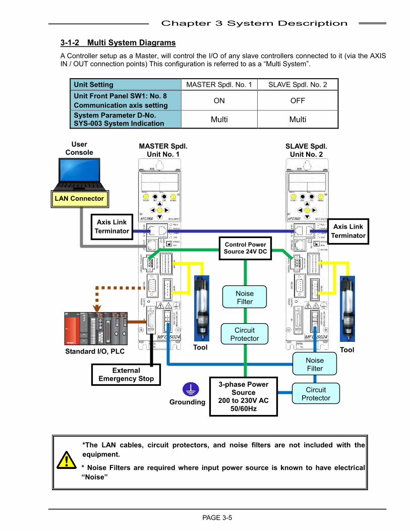
Chapter 3 System Description
PAGE 3-5
3-1-2 Multi System Diagrams A Controller setup as a Master, will control the I/O of any slave controllers connected to it (via the AXIS IN / OUT connection points) This configuration is referred to as a “Multi System”.
Unit Setting MASTER Spdl. No. 1 SLAVE Spdl. No. 2 Unit Front Panel SW1: No. 8 Communication axis setting ON OFF
System Parameter D-No. SYS-003 System Indication Multi Multi
*The LAN cables, circuit protectors, and noise filters are not included with the equipment.
* Noise Filters are required where input power source is known to have electrical “Noise”
Tool Tool
3-phase Power Source
200 to 230V AC 50/60Hz
User Console
MASTER Spdl. Unit No. 1
SLAVE Spdl. Unit No. 2
Axis Link Terminator
Axis Link Terminator
Control Power Source 24V DC
Noise Filter
Noise Filter
Circuit Protector
Circuit Protector
External Emergency Stop
Grounding
LAN Connector
Standard I/O, PLC
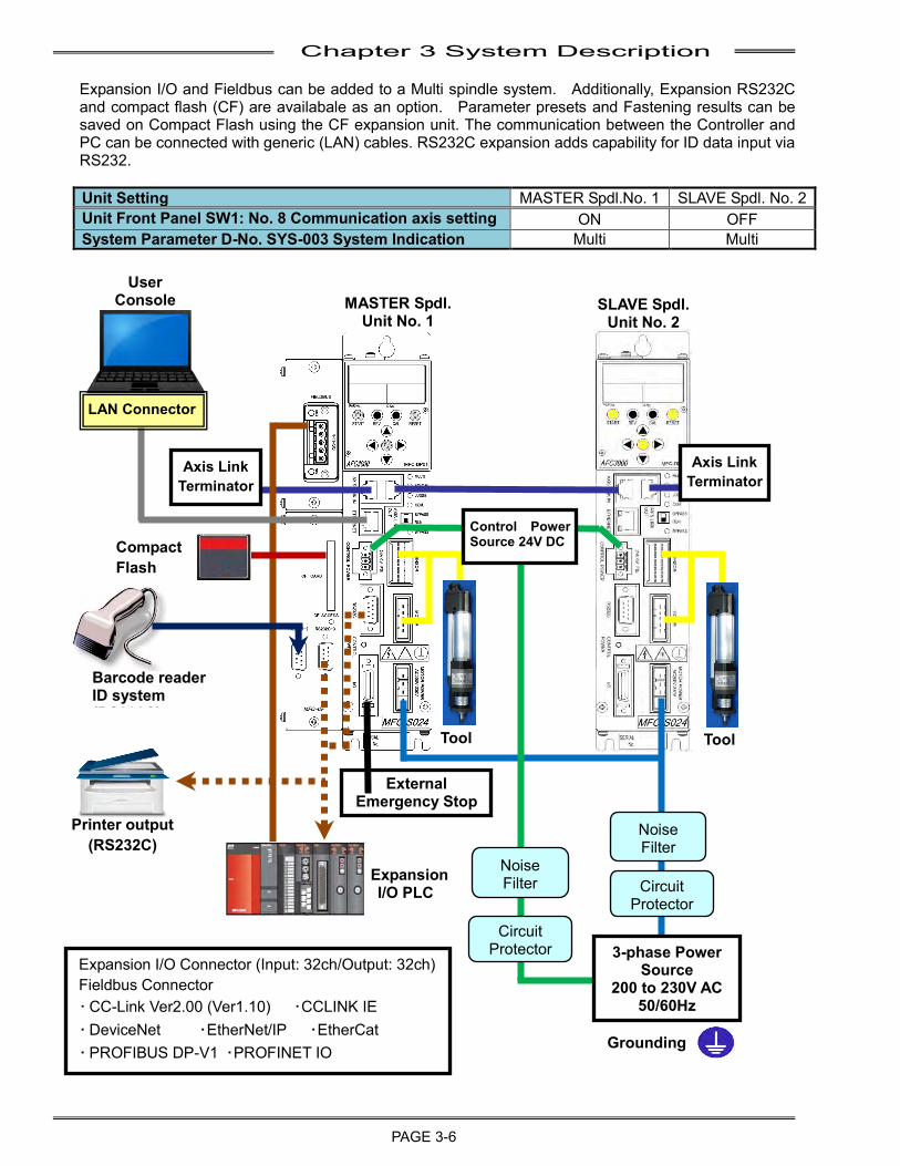
Chapter 3 System Description
PAGE 3-6
Expansion I/O and Fieldbus can be added to a Multi spindle system. Additionally, Expansion RS232C and compact flash (CF) are availabale as an option. Parameter presets and Fastening results can be saved on Compact Flash using the CF expansion unit. The communication between the Controller and PC can be connected with generic (LAN) cables. RS232C expansion adds capability for ID data input via RS232. Unit Setting MASTER Spdl.No. 1 SLAVE Spdl. No. 2 Unit Front Panel SW1: No. 8 Communication axis setting ON OFF System Parameter D-No. SYS-003 System Indication Multi Multi
Tool
Printer output (RS232C)
Barcode reader ID system (RS232C)
Expansion I/O PLC
Expansion I/O Connector (Input: 32ch/Output: 32ch) Fieldbus Connector ・ CC-Link Ver2.00 (Ver1.10) ・CCLINK IE ・ DeviceNet ・EtherNet/IP ・EtherCat ・ PROFIBUS DP-V1 ・PROFINET IO
Tool
Compact Flash
Control Power Source 24V DC
LAN Connector
User Console
Axis Link Terminator
Axis Link Terminator
MASTER Spdl. Unit No. 1
SLAVE Spdl. Unit No. 2
Noise Filter
Noise Filter Circuit
Protector
Circuit Protector
Grounding
3-phase Power Source
200 to 230V AC 50/60Hz
External Emergency Stop
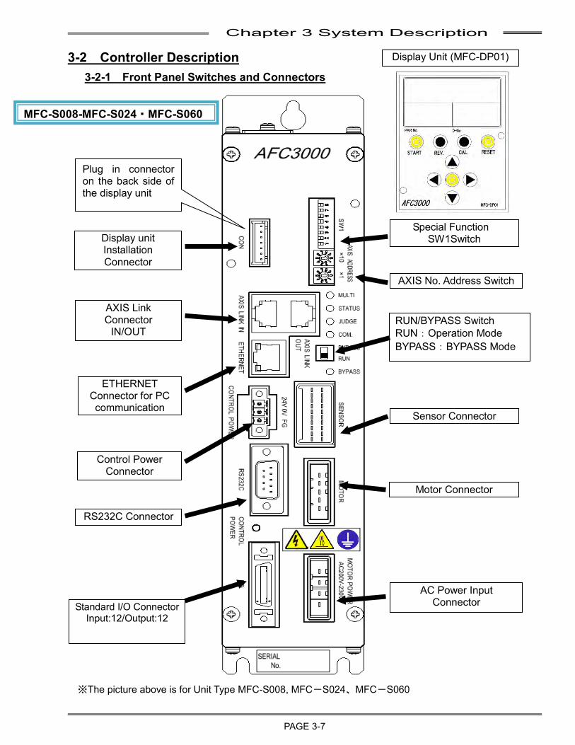
Chapter 3 System Description
PAGE 3-7
3-2 Controller Description
3-2-1 Front Panel Switches and Connectors
※The picture above is for Unit Type MFC-S008, MFC-S024、MFC-S060
RUN/BYPASS Switch RUN:Operation Mode BYPASS:BYPASS Mode
AXIS Link Connector
IN/OUT
Standard I/O Connector Input:12/Output:12
Sensor Connector
Motor Connector
AC Power Input Connector
Display unit Installation Connector
ETHERNET Connector for PC communication
Display Unit (MFC-DP01)
Plug in connector on the back side of the display unit
MFC-S008-MFC-S024・MFC-S060
RS232C Connector
Control Power Connector
AXIS No. Address Switch
Special Function SW1Switch
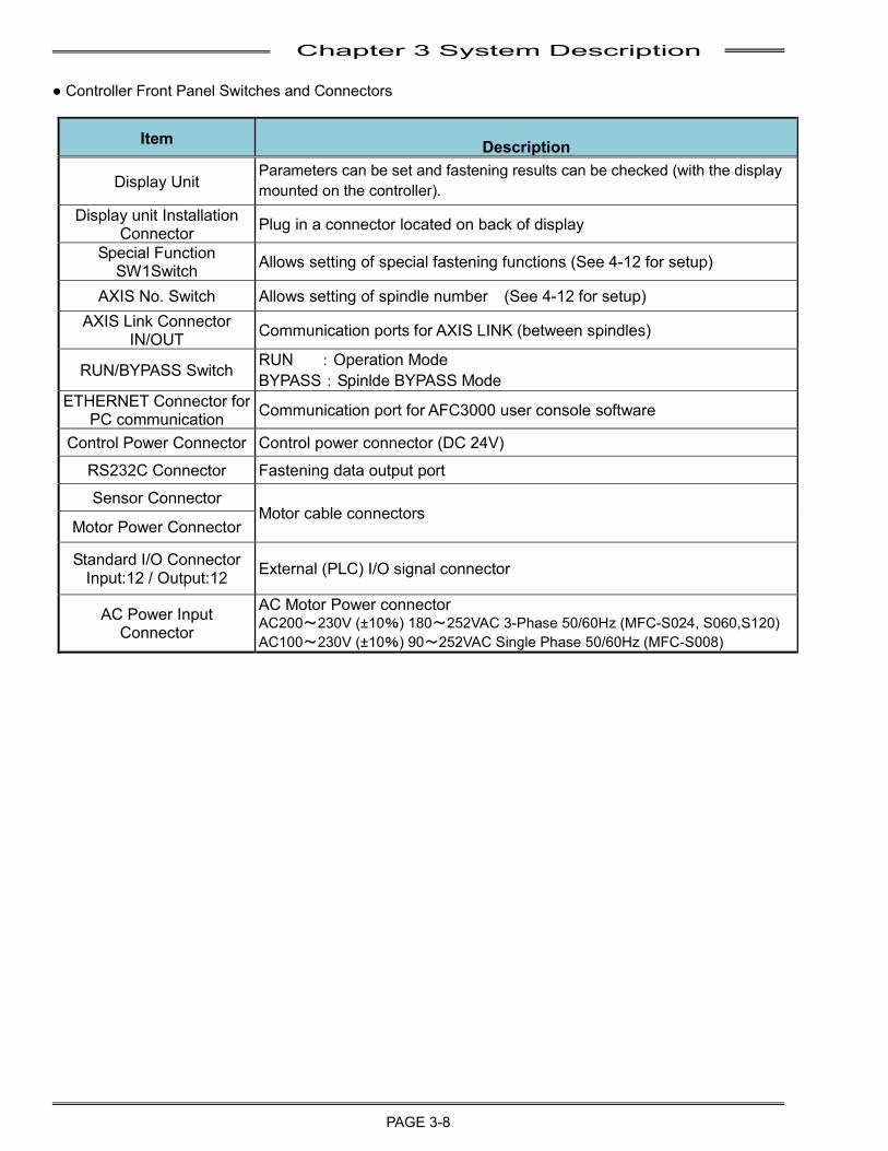
Chapter 3 System Description
PAGE 3-8
● Controller Front Panel Switches and Connectors
Item Description
Display Unit Parameters can be set and fastening results can be checked (with the display mounted on the controller).
Display unit Installation Connector Plug in a connector located on back of display
Special Function SW1Switch Allows setting of special fastening functions (See 4-12 for setup)
AXIS No. Switch Allows setting of spindle number (See 4-12 for setup) AXIS Link Connector
IN/OUT Communication ports for AXIS LINK (between spindles)
RUN/BYPASS Switch RUN :Operation Mode BYPASS:Spinlde BYPASS Mode
ETHERNET Connector for PC communication Communication port for AFC3000 user console software
Control Power Connector Control power connector (DC 24V)
RS232C Connector Fastening data output port
Sensor Connector Motor cable connectors
Motor Power Connector
Standard I/O Connector Input:12 / Output:12 External (PLC) I/O signal connector
AC Power Input Connector
AC Motor Power connector AC200~230V (±10%) 180~252VAC 3-Phase 50/60Hz (MFC-S024, S060,S120) AC100~230V (±10%) 90~252VAC Single Phase 50/60Hz (MFC-S008)
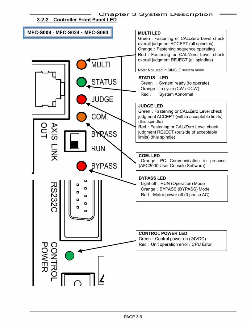
Chapter 3 System Description
PAGE 3-9
3-2-2 Controller Front Panel LED
MFC-S008 - MFC-S024・MFC-S060
BYPASS LED Light off:RUN (Operation) Mode Orange:BYPASS (BYPASS) Mode Red:Motor power off (3 phase AC)
STATUS LED Green :System ready (to operate) Orange:In cycle (CW / CCW) Red: System Abnormal
JUDGE LED Green:Fastening or CAL/Zero Level check judgment ACCEPT (within acceptable limits) (this spindle) Red:Fastening or CAL/Zero Level check judgment REJECT (outside of acceptable limits) (this spindle)
COM. LED Orange: PC Communication in process
(AFC3000 User Console Software)
CONTROL POWER LED Green:Control power on (24VDC) Red:Unit operation error / CPU Error
MULTI LED Green:Fastening or CAL/Zero Level check overall judgment ACCEPT (all spindles) Orange:Fastening sequence operating Red:Fastening or CAL/Zero Level check overall judgment REJECT (all spindles) Note: Not used in SINGLE system mode
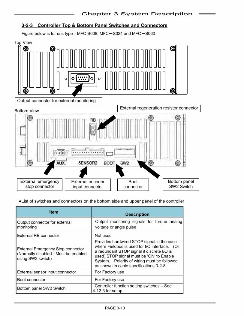
Chapter 3 System Description
PAGE 3-10
3-2-3 Controller Top & Bottom Panel Switches and Connectors Figure below is for unit type:MFC-S008, MFC-S024 and MFC-S060
Top View
Bottom View
●List of switches and connectors on the bottom side and upper panel of the controller
Item Description
Output connector for external monitoring
Output monitoring signals for torque analog voltage or angle pulse
External RB connector Not used
External Emergency Stop connector (Normally disabled - Must be enabled using SW2 switch)
Provides hardwired STOP signal in the case where Fieldbus is used for I/O interface. (Or a redundant STOP signal if discrete I/O is used) STOP signal must be ‘ON’ to Enable System. Polarity of wiring must be followed as shown in cable specifications 3-2-8.
External sensor input connector For Factory use
Boot connector For Factory use
Bottom panel SW2 Switch Controller function setting switches – See 4-12-3 for setup
Output connector for external monitoring External regeneration resistor connector
External emergency stop connector
External encoder input connector
Boot connector
Bottom panel SW2 Switch
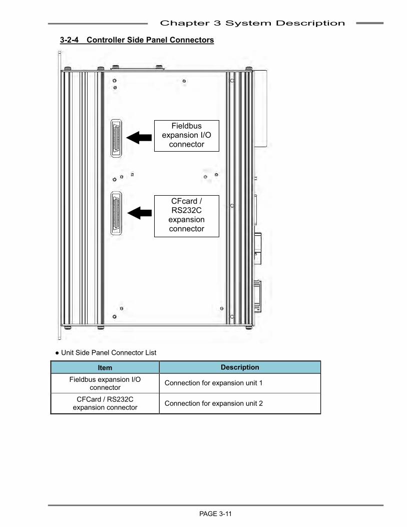
Chapter 3 System Description
PAGE 3-11
3-2-4 Controller Side Panel Connectors
● Unit Side Panel Connector List
Item Description Fieldbus expansion I/O
connector Connection for expansion unit 1
CFCard / RS232C expansion connector Connection for expansion unit 2
Fieldbus expansion I/O
connector
CFcard / RS232C
expansion connector
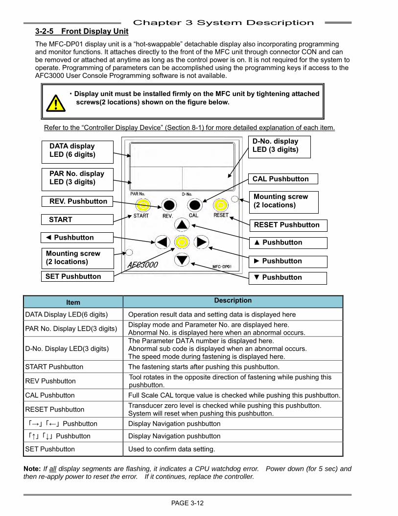
Chapter 3 System Description
PAGE 3-12
3-2-5 Front Display Unit The MFC-DP01 display unit is a “hot-swappable” detachable display also incorporating programming and monitor functions. It attaches directly to the front of the MFC unit through connector CON and can be removed or attached at anytime as long as the control power is on. It is not required for the system to operate. Programming of parameters can be accomplished using the programming keys if access to the AFC3000 User Console Programming software is not available.
・Display unit must be installed firmly on the MFC unit by tightening attached screws(2 locations) shown on the figure below.
Refer to the “Controller Display Device” (Section 8-1) for more detailed explanation of each item.
Item Description
DATA Display LED(6 digits) Operation result data and setting data is displayed here
PAR No. Display LED(3 digits) Display mode and Parameter No. are displayed here. Abnormal No. is displayed here when an abnormal occurs.
D-No. Display LED(3 digits) The Parameter DATA number is displayed here. Abnormal sub code is displayed when an abnormal occurs.
The speed mode during fastening is displayed here. START Pushbutton The fastening starts after pushing this pushbutton.
REV Pushbutton Tool rotates in the opposite direction of fastening while pushing this pushbutton.
CAL Pushbutton Full Scale CAL torque value is checked while pushing this pushbutton.
RESET Pushbutton Transducer zero level is checked while pushing this pushbutton. System will reset when pushing this pushbutton.
「→」「←」Pushbutton Display Navigation pushbutton
「↑」「↓」Pushbutton Display Navigation pushbutton
SET Pushbutton Used to confirm data setting. Note: If all display segments are flashing, it indicates a CPU watchdog error. Power down (for 5 sec) and then re-apply power to reset the error. If it continues, replace the controller.
SET Pushbutton
◄ Pushbutton
Mounting screw (2 locations)
START Pushbutton
REV. Pushbutton
DATA display LED (6 digits)
PAR No. display LED (3 digits)
RESET Pushbutton
► Pushbutton
▲ Pushbutton
▼ Pushbutton
CAL Pushbutton
D-No. display LED (3 digits)
Mounting screw (2 locations)
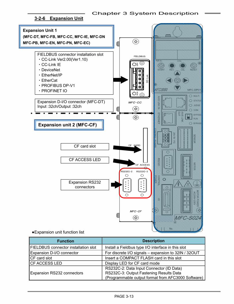
Chapter 3 System Description
PAGE 3-13
3-2-6 Expansion Unit
●Expansion unit function list
Function Description FIELDBUS connector installation slot Install a Fieldbus type I/O interface in this slot Expansion D-I/O connector For discrete I/O signals – expansion to 32IN / 32OUT CF card slot Insert a COMPACT FLASH card in this slot CF ACCESS LED Display LED for CF card mode
Expansion RS232 connectors RS232C-2: Data Input Connector (ID Data) RS232C-3: Output Fastening Results Data (Programmable output format from AFC3000 Software)
FIELDBUS connector installation slot ・CC-Link Ver2.00(Ver1.10) ・CC-Link IE ・DeviceNet ・EtherNet/IP ・EtherCat ・PROFIBUS DP-V1 ・PROFINET IO
CF card slot
CF ACCESS LED
Expansion RS232 connectors
Expansion Unit 1 (MFC-DT, MFC-FB, MFC-CC, MFC-IE, MFC-DN MFC-PB, MFC-EN, MFC-PN, MFC-EC)
Expansion unit 2 (MFC-CF)
Expansion D-I/O connector (MFC-DT) Input :32ch/Output :32ch
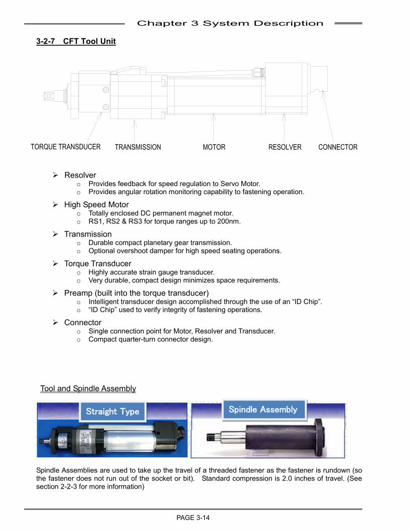
Chapter 3 System Description
PAGE 3-14
3-2-7 CFT Tool Unit
➢ Resolver o Provides feedback for speed regulation to Servo Motor. o Provides angular rotation monitoring capability to fastening operation.
➢ High Speed Motor o Totally enclosed DC permanent magnet motor. o RS1, RS2 & RS3 for torque ranges up to 200nm.
➢ Transmission o Durable compact planetary gear transmission. o Optional overshoot damper for high speed seating operations.
➢ Torque Transducer o Highly accurate strain gauge transducer. o Very durable, compact design minimizes space requirements.
➢ Preamp (built into the torque transducer) o Intelligent transducer design accomplished through the use of an “ID Chip”. o “ID Chip” used to verify integrity of fastening operations.
➢ Connector o Single connection point for Motor, Resolver and Transducer. o Compact quarter-turn connector design.
Tool and Spindle Assembly
Spindle Assemblies are used to take up the travel of a threaded fastener as the fastener is rundown (so the fastener does not run out of the socket or bit). Standard compression is 2.0 inches of travel. (See section 2-2-3 for more information)
Straight Type
Spindle Assembly
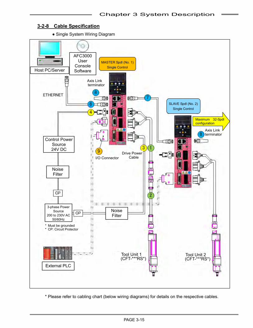
Chapter 3 System Description
PAGE 3-15
3-2-8 Cable Specification
● Single System Wiring Diagram
* Please refer to cabling chart (below wiring diagrams) for details on the respective cables.
Host PC/Server
AFC3000 User
Console Software
Control Power Source 24V DC
Noise Filter
3-phase Power Source
200 to 230V AC 50/60Hz
* Must be grounded * CP: Circuit Protector
Noise Filter
External PLC
Tool Unit 1 (CFT-***RS*)
Tool Unit 2 (CFT-***RS*)
I/O Connector Drive Power
Cable
Axis Link terminator
Axis Link terminator
SLAVE Spdl (No. 2) Single Control
MASTER Spdl (No. 1) Single Control
Maximum 32-Spdl configuration
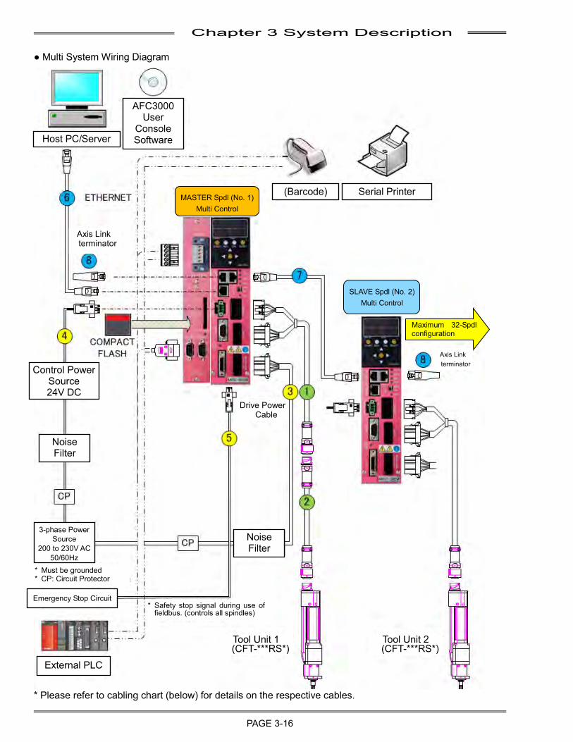
Chapter 3 System Description
PAGE 3-16
● Multi System Wiring Diagram
* Please refer to cabling chart (below) for details on the respective cables.
Maximum 32-Spdl configuration
Host PC/Server
AFC3000 User
Console Software
MASTER Spdl (No. 1) Multi Control
(Barcode) Serial Printer
SLAVE Spdl (No. 2) Multi Control
Axis Link terminator
Axis Link terminator
Drive Power Cable
Control Power Source 24V DC
Noise Filter
3-phase Power Source
200 to 230V AC 50/60Hz
* Must be grounded * CP: Circuit Protector
* Safety stop signal during use of fieldbus. (controls all spindles)
Tool Unit 1 (CFT-***RS*)
Tool Unit 2 (CFT-***RS*)
Noise Filter
External PLC
Emergency Stop Circuit
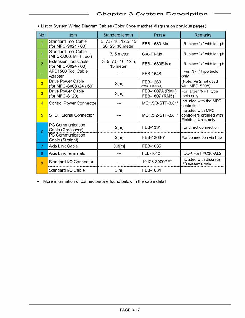
Chapter 3 System Description
PAGE 3-17
● List of System Wiring Diagram Cables (Color Code matches diagram on previous pages)
No. Item Standard length Part # Remarks
1 Standard Tool Cable (for MFC-S024 / 60)
5, 7.5, 10, 12.5, 15, 20, 25, 30 meter FEB-1630-Mx Replace “x” with length
1 Standard Tool Cable (MFC-S008, MFT Tool) 3, 5 meter C30-FT-Mx Replace “x” with length
2 Extension Tool Cable (for MFC-S024 / 60)
3, 5, 7.5, 10, 12.5, 15 meter FEB-1630E-Mx Replace “x” with length
-- AFC1500 Tool Cable Adapter --- FEB-1648 For ‘NFT’ type tools
only
3 Drive Power Cable (for MFC-S008 /24 / 60) 3[m] FEB-1260
(Was FEB-1631) (Note: Pin2 not used with MFC-S008)
3 Drive Power Cable (for MFC-S120) 3[m] FEB-1607A (RM4)
FEB-1607 (RM5) For larger ‘NFT’ type tools only
4 Control Power Connector --- MC1.5/3-STF-3.81* Included with the MFC controller
5 STOP Signal Connector --- MC1.5/2-STF-3.81* Included with MFC controllers ordered with Fieldbus Units only
6 PC Communication Cable (Crossover) 2[m] FEB-1331 For direct connection
PC Communication Cable (Straight) 2[m] FEB-1268-7 For connection via hub
7 Axis Link Cable 0.3[m] FEB-1635
8 Axis Link Terminator --- FEB-1642 DDK Part #C30-AL2
9
Standard I/O Connector --- 10126-3000PE* Included with discrete I/O systems only
Standard I/O Cable 3[m] FEB-1634
• More information of connectors are found below in the cable detail
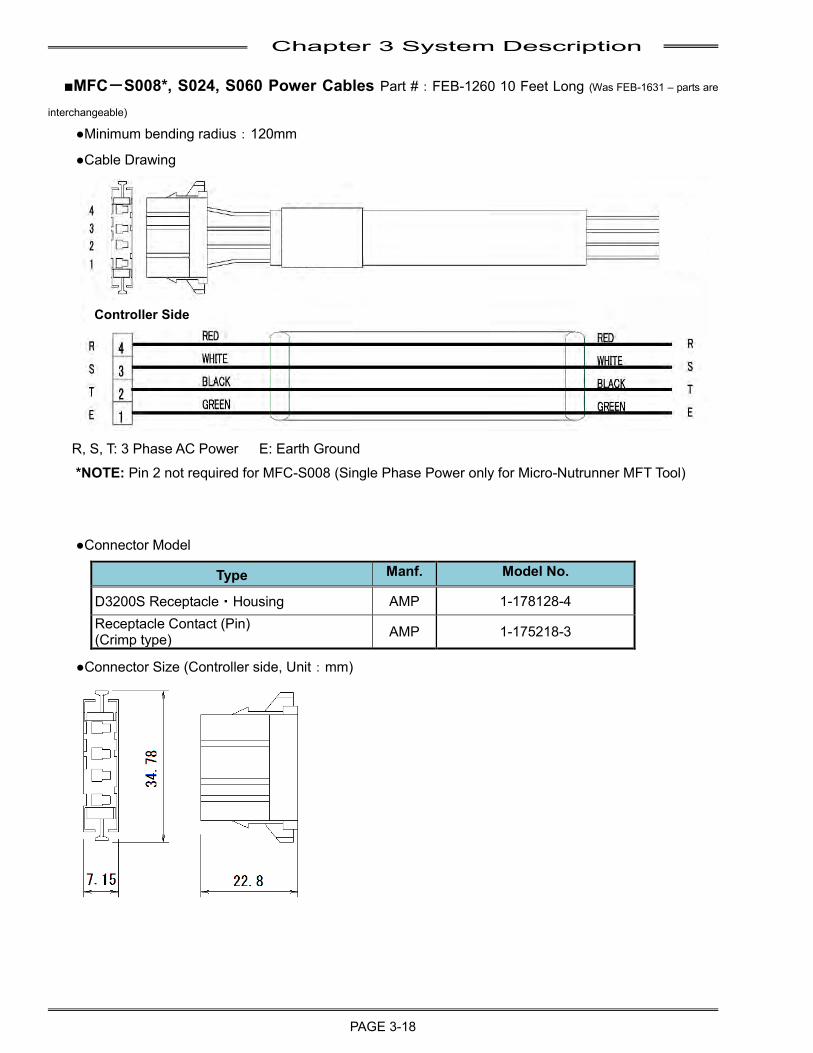
Chapter 3 System Description
PAGE 3-18
■MFC-S008*, S024, S060 Power Cables Part #:FEB-1260 10 Feet Long (Was FEB-1631 – parts are
interchangeable) ●Minimum bending radius:120mm
●Cable Drawing
R, S, T: 3 Phase AC Power E: Earth Ground
*NOTE: Pin 2 not required for MFC-S008 (Single Phase Power only for Micro-Nutrunner MFT Tool)
●Connector Model
Type Manf. Model No.
D3200S Receptacle・Housing AMP 1-178128-4 Receptacle Contact (Pin) (Crimp type) AMP 1-175218-3
●Connector Size (Controller side, Unit:mm)
Controller Side
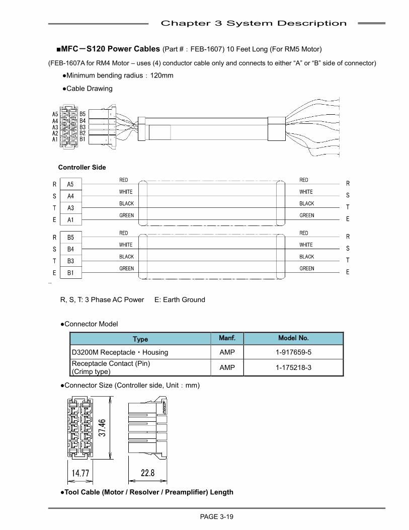
Chapter 3 System Description
PAGE 3-19
■MFC-S120 Power Cables (Part #:FEB-1607) 10 Feet Long (For RM5 Motor)
(FEB-1607A for RM4 Motor – uses (4) conductor cable only and connects to either “A” or “B” side of connector)
●Minimum bending radius:120mm
●Cable Drawing
R, S, T: 3 Phase AC Power E: Earth Ground
●Connector Model
Type Manf. Model No.
D3200M Receptacle・Housing AMP 1-917659-5 Receptacle Contact (Pin) (Crimp type) AMP 1-175218-3
●Connector Size (Controller side, Unit:mm)
●Tool Cable (Motor / Resolver / Preamplifier) Length
Controller Side
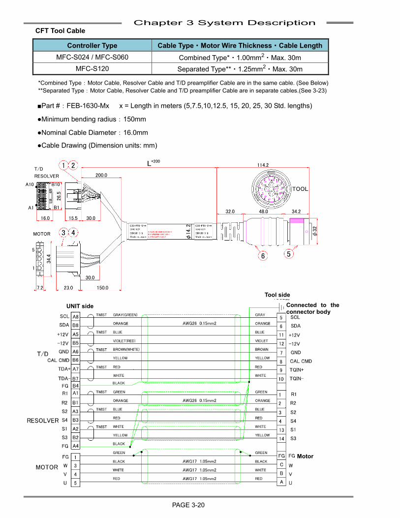
Chapter 3 System Description
PAGE 3-20
CFT Tool Cable
Controller Type Cable Type・Motor Wire Thickness・Cable Length MFC-S024 / MFC-S060 Combined Type*・1.00mm2・Max. 30m
MFC-S120 Separated Type**・1.25mm2・Max. 30m
*Combined Type:Motor Cable, Resolver Cable and T/D preamplifier Cable are in the same cable. (See Below) **Separated Type:Motor Cable, Resolver Cable and T/D preamplifier Cable are in separate cables.(See 3-23)
■Part #:FEB-1630-Mx x = Length in meters (5,7.5,10,12.5, 15, 20, 25, 30 Std. lengths)
●Minimum bending radius:150mm
●Nominal Cable Diameter:16.0mm
●Cable Drawing (Dimension units: mm)
UNIT side
Tool side
Motor
Connected to the connector body
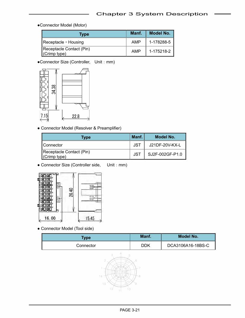
Chapter 3 System Description
PAGE 3-21
●Connector Model (Motor)
Type Manf. Model No.
Receptacle・Housing AMP 1-178288-5 Receptacle Contact (Pin) (Crimp type) AMP 1-175218-2
●Connector Size (Controller, Unit:mm)
● Connector Model (Resolver & Preamplifier)
Type Manf. Model No.
Connector JST J21DF-20V-KX-L Receptacle Contact (Pin) (Crimp type) JST SJ2F-002GF-P1.0
● Connector Size (Controller side, Unit:mm)
● Connector Model (Tool side)
Type Manf. Model No.
Connector DDK DCA3106A16-18BS-C
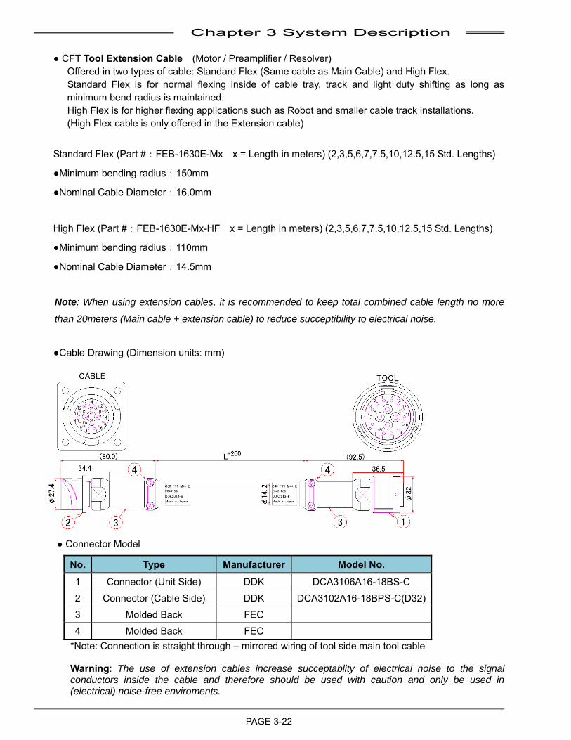
Chapter 3 System Description
PAGE 3-22
● CFT Tool Extension Cable (Motor / Preamplifier / Resolver)
Offered in two types of cable: Standard Flex (Same cable as Main Cable) and High Flex. Standard Flex is for normal flexing inside of cable tray, track and light duty shifting as long as minimum bend radius is maintained. High Flex is for higher flexing applications such as Robot and smaller cable track installations. (High Flex cable is only offered in the Extension cable)
Standard Flex (Part #:FEB-1630E-Mx x = Length in meters) (2,3,5,6,7,7.5,10,12.5,15 Std. Lengths)
●Minimum bending radius:150mm
●Nominal Cable Diameter:16.0mm
High Flex (Part #:FEB-1630E-Mx-HF x = Length in meters) (2,3,5,6,7,7.5,10,12.5,15 Std. Lengths)
●Minimum bending radius:110mm
●Nominal Cable Diameter:14.5mm
Note: When using extension cables, it is recommended to keep total combined cable length no more
than 20meters (Main cable + extension cable) to reduce succeptibility to electrical noise.
●Cable Drawing (Dimension units: mm)
● Connector Model
No. Type Manufacturer Model No. 1 Connector (Unit Side) DDK DCA3106A16-18BS-C 2 Connector (Cable Side) DDK DCA3102A16-18BPS-C(D32) 3 Molded Back FEC 4 Molded Back FEC
*Note: Connection is straight through – mirrored wiring of tool side main tool cable Warning: The use of extension cables increase succeptablity of electrical noise to the signal conductors inside the cable and therefore should be used with caution and only be used in (electrical) noise-free enviroments.
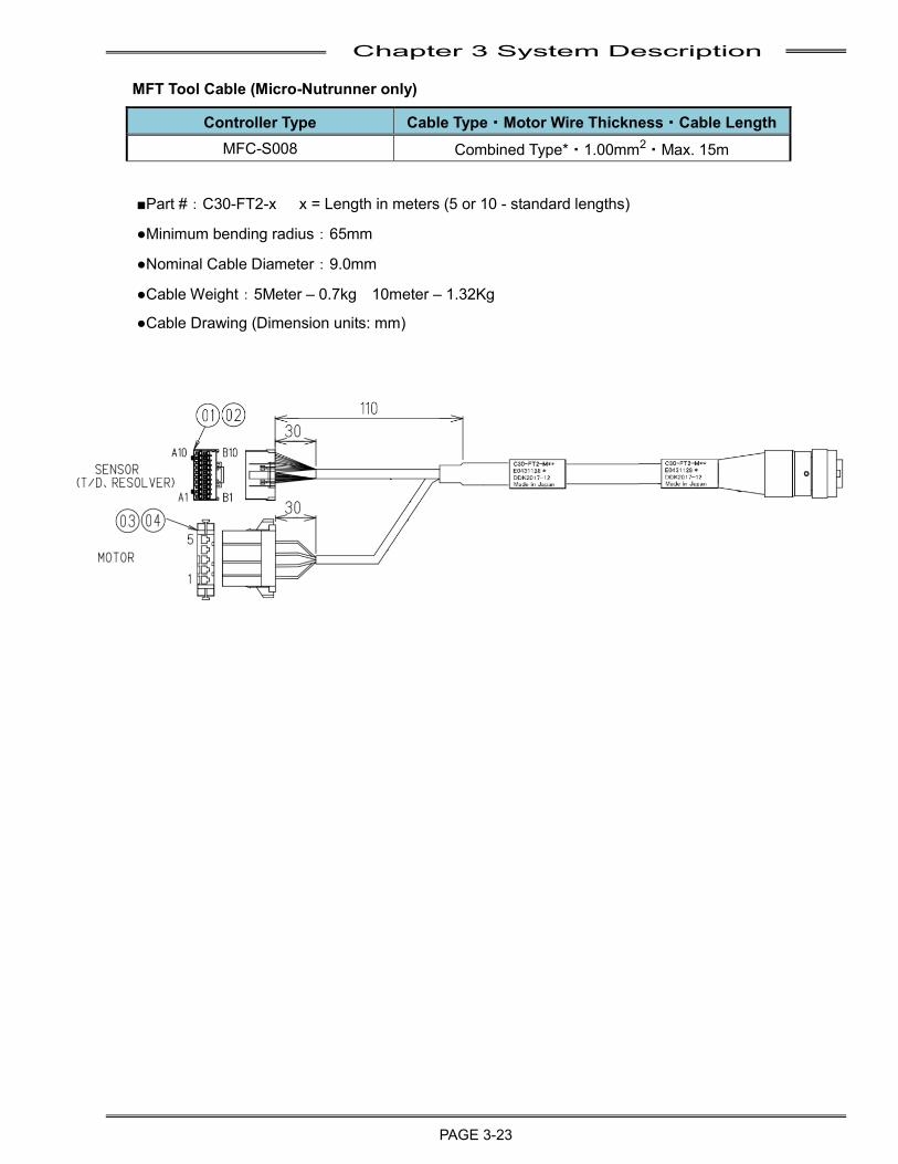
Chapter 3 System Description
PAGE 3-23
MFT Tool Cable (Micro-Nutrunner only)
Controller Type Cable Type・Motor Wire Thickness・Cable Length MFC-S008 Combined Type*・1.00mm2・Max. 15m
■Part #:C30-FT2-x x = Length in meters (5 or 10 - standard lengths)
●Minimum bending radius:65mm
●Nominal Cable Diameter:9.0mm
●Cable Weight:5Meter – 0.7kg 10meter – 1.32Kg
●Cable Drawing (Dimension units: mm)
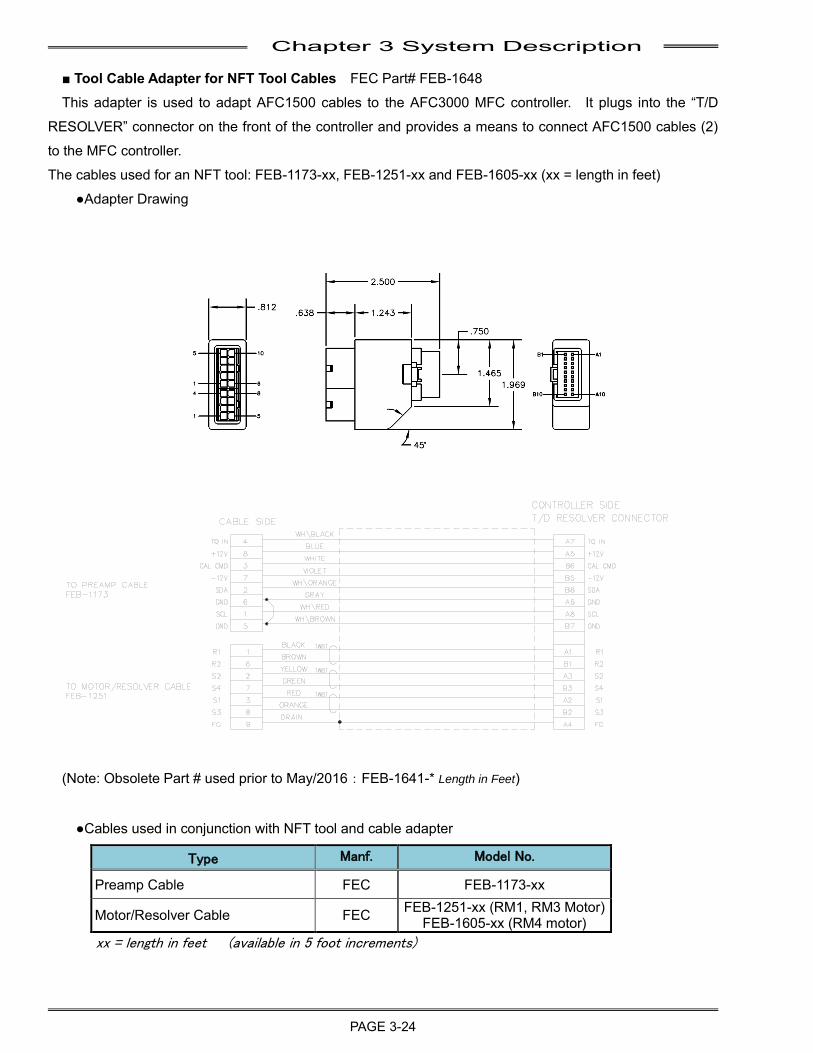
Chapter 3 System Description
PAGE 3-24
■ Tool Cable Adapter for NFT Tool Cables FEC Part# FEB-1648
This adapter is used to adapt AFC1500 cables to the AFC3000 MFC controller. It plugs into the “T/D
RESOLVER” connector on the front of the controller and provides a means to connect AFC1500 cables (2)
to the MFC controller.
The cables used for an NFT tool: FEB-1173-xx, FEB-1251-xx and FEB-1605-xx (xx = length in feet)
●Adapter Drawing
(Note: Obsolete Part # used prior to May/2016:FEB-1641-* Length in Feet)
●Cables used in conjunction with NFT tool and cable adapter
Type Manf. Model No.
Preamp Cable FEC FEB-1173-xx
Motor/Resolver Cable FEC FEB-1251-xx (RM1, RM3 Motor) FEB-1605-xx (RM4 motor)
xx = length in feet (available in 5 foot increments)
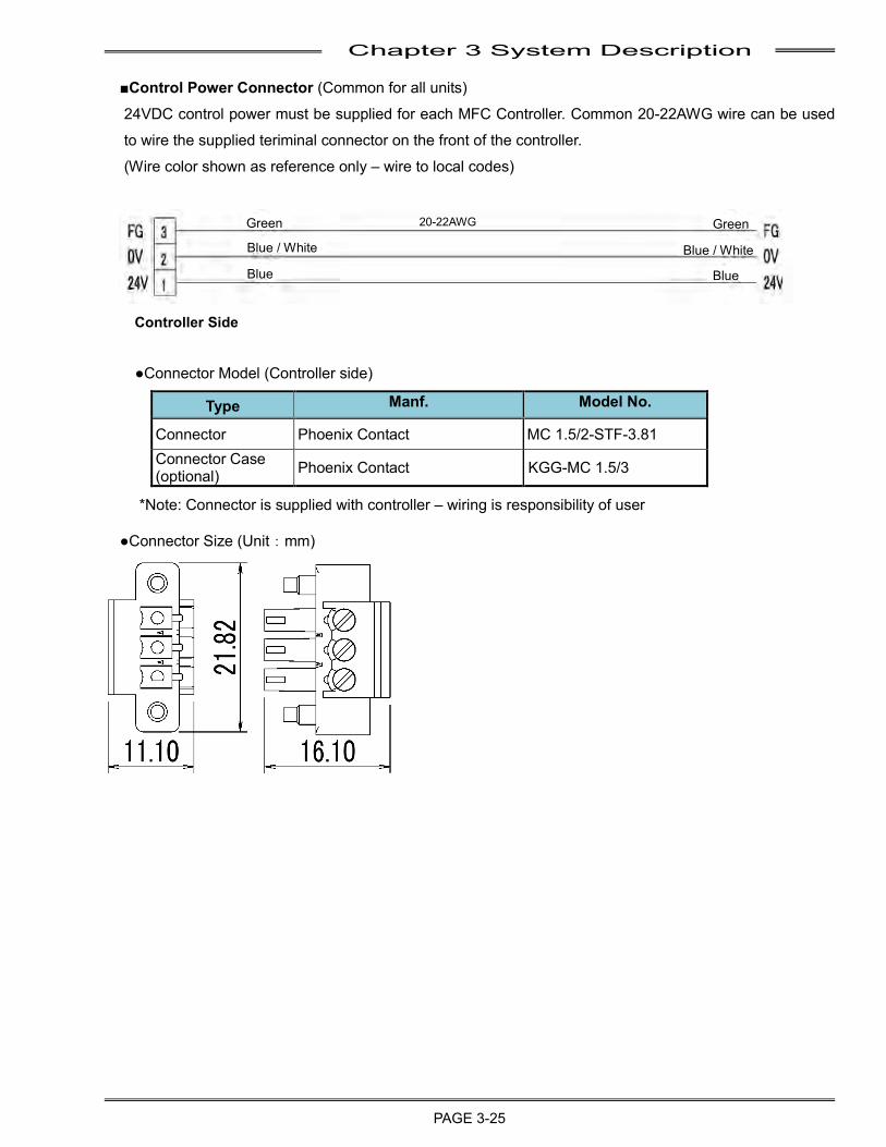
Chapter 3 System Description
PAGE 3-25
Green
Blue / White
Blue
20-22AWG Green
Blue
Blue / White
■Control Power Connector (Common for all units)
24VDC control power must be supplied for each MFC Controller. Common 20-22AWG wire can be used
to wire the supplied teriminal connector on the front of the controller.
(Wire color shown as reference only – wire to local codes)
●Connector Model (Controller side)
Type Manf. Model No.
Connector Phoenix Contact MC 1.5/2-STF-3.81 Connector Case (optional) Phoenix Contact KGG-MC 1.5/3
*Note: Connector is supplied with controller – wiring is responsibility of user
●Connector Size (Unit:mm)
Controller Side
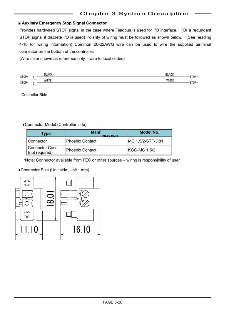
Chapter 3 System Description
PAGE 3-26
■ Auxilary Emergency Stop Signal Connector
Provides hardwired STOP signal in the case where Fieldbus is used for I/O interface. (Or a redundant
STOP signal if discrete I/O is used) Polarity of wiring must be followed as shown below. (See heading
4-10 for wiring information) Common 20-22AWG wire can be used to wire the supplied teriminal
connector on the bottom of the controller.
(Wire color shown as reference only – wire to local codes)
●Connector Model (Controller side)
Type Manf. Model No.
Connector Phoenix Contact MC 1,5/2-STF-3,81 Connector Case (not required) Phoenix Contact KGG-MC 1.5/2
*Note: Connector available from FEC or other sources – wiring is responsibility of user
●Connector Size (Unit side, Unit:mm)
Controller Side
20-22AWG
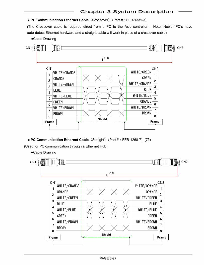
Chapter 3 System Description
PAGE 3-27
■ PC Communication Ethernet Cable(Crossover)(Part #:FEB-1331-3)
(The Crossover cable is required direct from a PC to the Axis controller – Note: Newer PC’s have
auto-detect Ethernet hardware and a straight cable will work in place of a crossover cable)
●Cable Drawing
■ PC Communication Ethernet Cable(Straight)(Part #:FEB-1268-7)(7ft)
(Used for PC communication through a Ethernet Hub)
●Cable Drawing
Frame Frame Shield
Shield Frame Frame
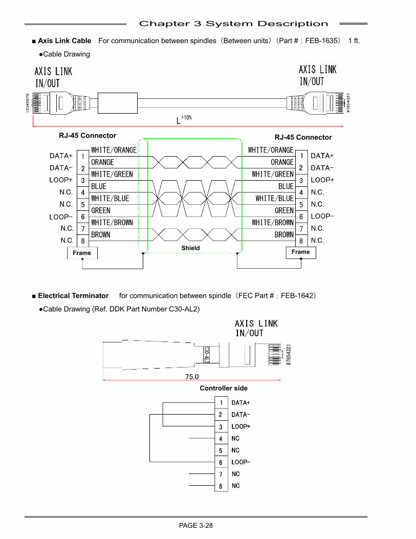
Chapter 3 System Description
PAGE 3-28
■ Axis Link Cable For communication between spindles(Between units)(Part #:FEB-1635) 1 ft.
●Cable Drawing
■ Electrical Terminator for communication between spindle(FEC Part #:FEB-1642)
●Cable Drawing (Ref. DDK Part Number C30-AL2)
Frame Frame Shield
RJ-45 Connector RJ-45 Connector
Controller side
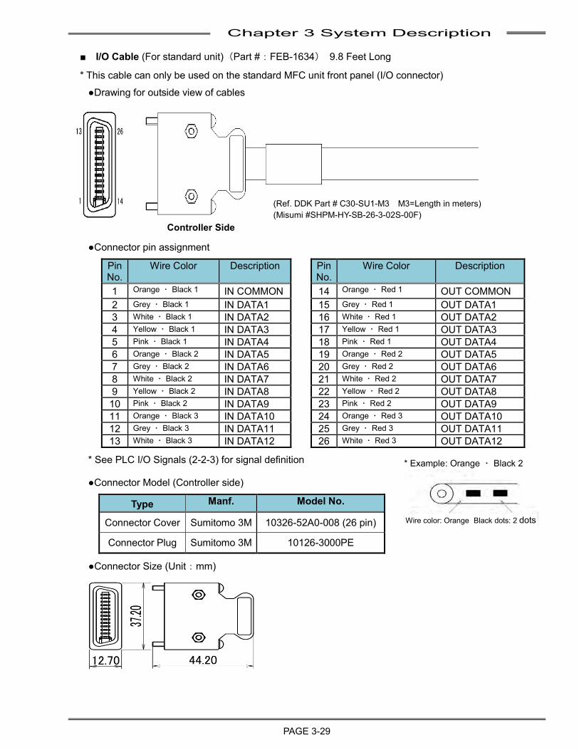
Chapter 3 System Description
PAGE 3-29
■ I/O Cable (For standard unit)(Part #:FEB-1634) 9.8 Feet Long
* This cable can only be used on the standard MFC unit front panel (I/O connector)
●Drawing for outside view of cables
●Connector pin assignment
Pin No.
Wire Color Description Pin No.
Wire Color Description
1 Orange ・ Black 1 IN COMMON 14 Orange ・ Red 1 OUT COMMON 2 Grey ・ Black 1 IN DATA1 15 Grey ・ Red 1 OUT DATA1 3 White ・ Black 1 IN DATA2 16 White ・ Red 1 OUT DATA2 4 Yellow ・ Black 1 IN DATA3 17 Yellow ・ Red 1 OUT DATA3 5 Pink ・ Black 1 IN DATA4 18 Pink ・ Red 1 OUT DATA4 6 Orange ・ Black 2 IN DATA5 19 Orange ・ Red 2 OUT DATA5 7 Grey ・ Black 2 IN DATA6 20 Grey ・ Red 2 OUT DATA6 8 White ・ Black 2 IN DATA7 21 White ・ Red 2 OUT DATA7 9 Yellow ・ Black 2 IN DATA8 22 Yellow ・ Red 2 OUT DATA8 10 Pink ・ Black 2 IN DATA9 23 Pink ・ Red 2 OUT DATA9 11 Orange ・ Black 3 IN DATA10 24 Orange ・ Red 3 OUT DATA10 12 Grey ・ Black 3 IN DATA11 25 Grey ・ Red 3 OUT DATA11 13 White ・ Black 3 IN DATA12 26 White ・ Red 3 OUT DATA12
* See PLC I/O Signals (2-2-3) for signal definition
●Connector Model (Controller side)
Type Manf. Model No.
Connector Cover Sumitomo 3M 10326-52A0-008 (26 pin)
Connector Plug Sumitomo 3M 10126-3000PE
●Connector Size (Unit:mm)
Controller Side
(Ref. DDK Part # C30-SU1-M3 M3=Length in meters) (Misumi #SHPM-HY-SB-26-3-02S-00F)
* Example: Orange ・ Black 2
Wire color: Orange Black dots: 2 dots
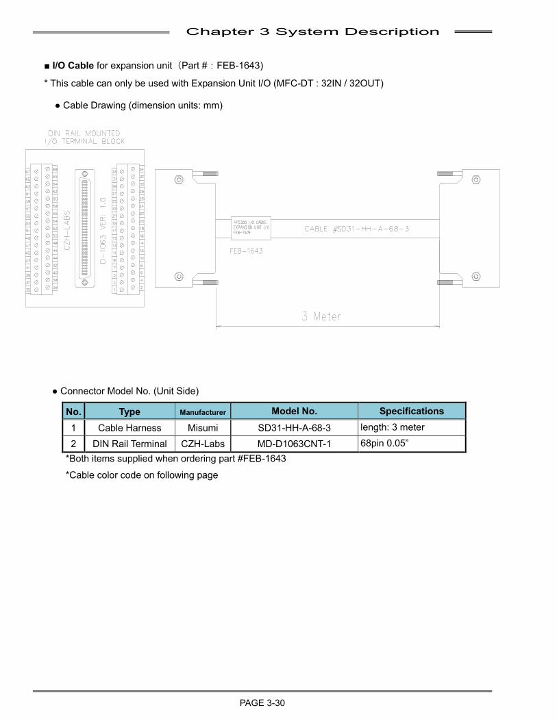
Chapter 3 System Description
PAGE 3-30
■ I/O Cable for expansion unit(Part #:FEB-1643)
* This cable can only be used with Expansion Unit I/O (MFC-DT : 32IN / 32OUT)
● Cable Drawing (dimension units: mm)
● Connector Model No. (Unit Side)
No. Type Manufacturer Model No. Specifications 1 Cable Harness Misumi SD31-HH-A-68-3 length: 3 meter
2 DIN Rail Terminal CZH-Labs MD-D1063CNT-1 68pin 0.05” *Both items supplied when ordering part #FEB-1643
*Cable color code on following page
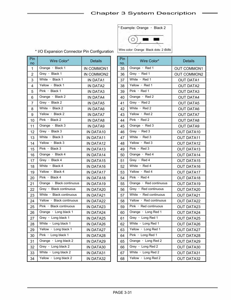
Chapter 3 System Description
PAGE 3-31
* I/O Expansion Connector Pin Configuration Pin no Wire Color* Details Pin
no. Wire Color* Details
1 Orange ・ Black 1 IN COMMON1 35 Orange ・ Red 1 OUT COMMON1 2 Grey ・ Black 1 IN COMMON2 36 Grey ・ Red 1 OUT COMMON2 3 White ・ Black 1 IN DATA1 37 White ・ Red 1 OUT DATA1 4 Yellow ・ Black 1 IN DATA2 38 Yellow ・ Red 1 OUT DATA2 5 Pink ・ Black 1 IN DATA3 39 Pink ・ Red 1 OUT DATA3 6 Orange ・ Black 2 IN DATA4 40 Orange ・ Red 2 OUT DATA4 7 Grey ・ Black 2 IN DATA5 41 Grey ・ Red 2 OUT DATA5 8 White ・ Black 2 IN DATA6 42 White ・ Red 2 OUT DATA6 9 Yellow ・ Black 2 IN DATA7 43 Yellow ・ Red 2 OUT DATA7 10 Pink ・ Black 2 IN DATA8 44 Pink ・ Red 2 OUT DATA8 11 Orange ・ Black 3 IN DATA9 45 Orange ・ Red 3 OUT DATA9 12 Grey ・ Black 3 IN DATA10 46 Grey ・ Red 3 OUT DATA10 13 White ・ Black 3 IN DATA11 47 White ・ Red 3 OUT DATA11 14 Yellow ・ Black 3 IN DATA12 48 Yellow ・ Red 3 OUT DATA12 15 Pink ・ Black 3 IN DATA13 49 Pink ・ Red 3 OUT DATA13 16 Orange ・ Black 4 IN DATA14 50 Orange ・ Red 4 OUT DATA14 17 Grey ・ Black 4 IN DATA15 51 Grey ・ Red 4 OUT DATA15 18 White ・ Black 4 IN DATA16 52 White ・ Red 4 OUT DATA16 19 Yellow ・ Black 4 IN DATA17 53 Yellow ・ Red 4 OUT DATA17 20 Pink ・ Black 4 IN DATA18 54 Pink ・ Red 4 OUT DATA18 21 Orange ・ Black continuous IN DATA19 55 Orange ・ Red continuous OUT DATA19 22 Grey ・ Black continuous IN DATA20 56 Grey ・ Red continuous OUT DATA20 23 White ・ Black continuous IN DATA21 57 White ・ Red continuous OUT DATA21 24 Yellow ・ Black continuous IN DATA22 58 Yellow ・ Red continuous OUT DATA22 25 Pink ・ Black continuous IN DATA23 59 Pink ・ Red continuous OUT DATA23 26 Orange ・ Long black 1 IN DATA24 60 Orange ・ Long Red 1 OUT DATA24 27 Grey ・ Long black 1 IN DATA25 61 Grey ・ Long Red 1 OUT DATA25 28 White ・ Long black 1 IN DATA26 62 White ・ Long Red 1 OUT DATA26 29 Yellow ・ Long black 1 IN DATA27 63 Yellow ・ Long Red 1 OUT DATA27 30 Pink ・ Long black 1 IN DATA28 64 Pink ・ Long Red 1 OUT DATA28 31 Orange ・ Long black 2 IN DATA29 65 Orange ・ Long Red 2 OUT DATA29 32 Grey ・ Long black 2 IN DATA30 66 Grey ・ Long Red 2 OUT DATA30 33 White ・ Long black 2 IN DATA31 67 White ・ Long Red 2 OUT DATA31 34 Yellow ・ Long black 2 IN DATA32 68 Yellow ・ Long Red 2 OUT DATA32
* Example: Orange ・ Black 2
Wire color: Orange Black dots: 2 dots

Chapter 3 System Description
PAGE 3-32
(Blank Page)

Chapter 4 Installation and Wiring
PAGE 4-1
Chapter 4: Installation and Wiring
4
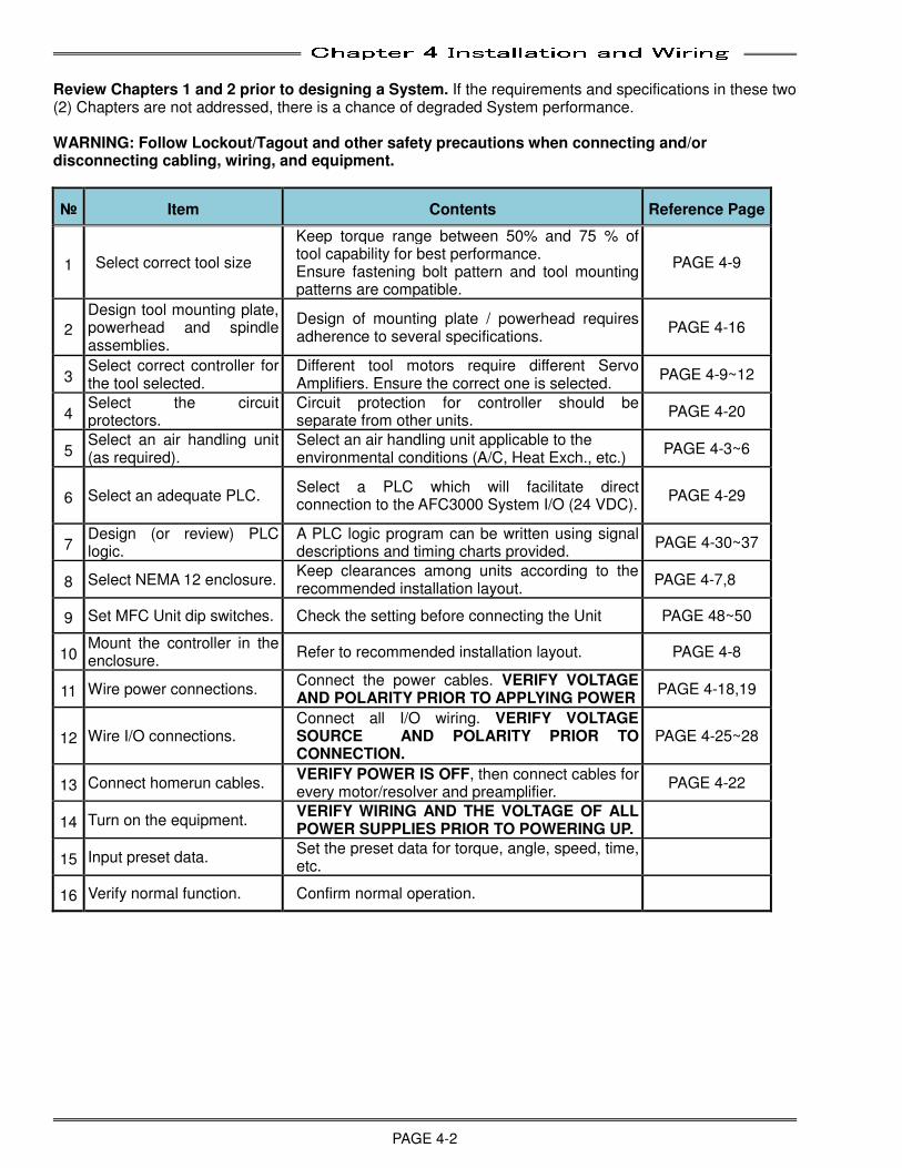
Chapter 4 Installation and Wiring
PAGE 4-2
Review Chapters 1 and 2 prior to designing a System. If the requirements and specifications in these two (2) Chapters are not addressed, there is a chance of degraded System performance. WARNING: Follow Lockout/Tagout and other safety precautions when connecting and/or disconnecting cabling, wiring, and equipment.
№ Item Contents Reference Page
1 Select correct tool size
Keep torque range between 50% and 75 % of tool capability for best performance. Ensure fastening bolt pattern and tool mounting patterns are compatible.
PAGE 4-9
2
Design tool mounting plate, powerhead and spindle assemblies.
Design of mounting plate / powerhead requires adherence to several specifications.
PAGE 4-16
3 Select correct controller for the tool selected.
Different tool motors require different Servo Amplifiers. Ensure the correct one is selected.
PAGE 4-9~12
4 Select the circuit protectors.
Circuit protection for controller should be separate from other units.
PAGE 4-20
5 Select an air handling unit (as required).
Select an air handling unit applicable to the environmental conditions (A/C, Heat Exch., etc.)
PAGE 4-3~6
6 Select an adequate PLC. Select a PLC which will facilitate direct connection to the AFC3000 System I/O (24 VDC).
PAGE 4-29
7 Design (or review) PLC logic.
A PLC logic program can be written using signal descriptions and timing charts provided.
PAGE 4-30~37
8 Select NEMA 12 enclosure. Keep clearances among units according to the recommended installation layout.
PAGE 4-7,8
9 Set MFC Unit dip switches. Check the setting before connecting the Unit PAGE 48~50
10 Mount the controller in the enclosure.
Refer to recommended installation layout. PAGE 4-8
11 Wire power connections. Connect the power cables. VERIFY VOLTAGE AND POLARITY PRIOR TO APPLYING POWER
PAGE 4-18,19
12 Wire I/O connections. Connect all I/O wiring. VERIFY VOLTAGE SOURCE AND POLARITY PRIOR TO CONNECTION.
PAGE 4-25~28
13 Connect homerun cables. VERIFY POWER IS OFF, then connect cables for every motor/resolver and preamplifier.
PAGE 4-22
14 Turn on the equipment. VERIFY WIRING AND THE VOLTAGE OF ALL POWER SUPPLIES PRIOR TO POWERING UP.
15 Input preset data. Set the preset data for torque, angle, speed, time, etc.
16 Verify normal function. Confirm normal operation.
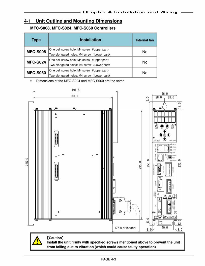
Chapter 4 Installation and Wiring
PAGE 4-3
4-1 Unit Outline and Mounting Dimensions
MFC-S008, MFC-S024, MFC-S060 Controllers
Type Installation Internal fan
MFC-S008 One bell screw hole: M4 screw(Upper part)
Two elongated holes: M4 screw(Lower part) No
MFC-S024 One bell screw hole: M4 screw(Upper part)
Two elongated holes: M4 screw(Lower part) No
MFC-S060 One bell screw hole: M4 screw(Upper part)
Two elongated holes: M4 screw(Lower part) No
• Dimensions of the MFC-S024 and MFC-S060 are the same.
【【【【Caution】】】】
Install the unit firmly with specified screws mentioned above to prevent the unit
from falling due to vibration (which could cause faulty operation)
(75.0 or longer)
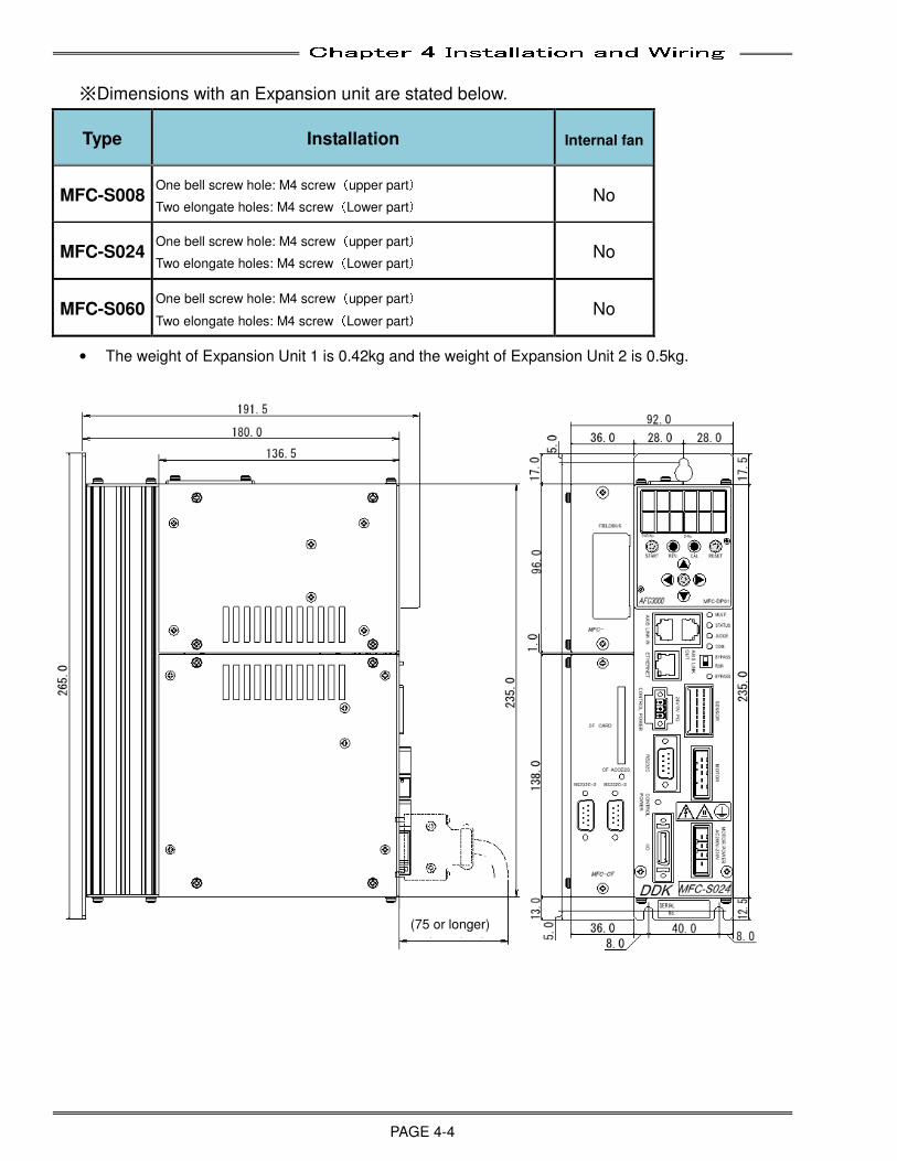
Chapter 4 Installation and Wiring
PAGE 4-4
※Dimensions with an Expansion unit are stated below.
Type Installation Internal fan
MFC-S008 One bell screw hole: M4 screw(upper part)
Two elongate holes: M4 screw(Lower part) No
MFC-S024 One bell screw hole: M4 screw(upper part)
Two elongate holes: M4 screw(Lower part) No
MFC-S060 One bell screw hole: M4 screw(upper part)
Two elongate holes: M4 screw(Lower part) No
• The weight of Expansion Unit 1 is 0.42kg and the weight of Expansion Unit 2 is 0.5kg.
(75 or longer)
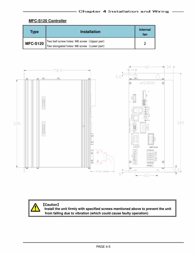
Chapter 4 Installation and Wiring
PAGE 4-5
MFC-S120 Controller
Type Installation Internal
fan
MFC-S120 Two bell screw holes: M6 screw(Upper part)
Two elongated holes: M6 screw(Lower part) 2
【【【【Caution】】】】
Install the unit firmly with specified screws mentioned above to prevent the unit
from falling due to vibration (which could cause faulty operation)
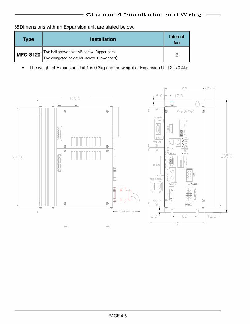
Chapter 4 Installation and Wiring
PAGE 4-6
※Dimensions with an Expansion unit are stated below.
Type Installation Internal
fan
MFC-S120 Two bell screw hole: M6 screw(upper part)
Two elongated holes: M6 screw(Lower part) 2
• The weight of Expansion Unit 1 is 0.3kg and the weight of Expansion Unit 2 is 0.4kg.
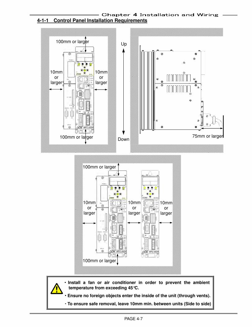
Chapter 4 Installation and Wiring
PAGE 4-7
4-1-1 Control Panel Installation Requirements
・・・・ Install a fan or air conditioner in order to prevent the ambient
temperature from exceeding 45°C. ・・・・Ensure no foreign objects enter the inside of the unit (through vents). ・・・・To ensure safe removal, leave 10mm min. between units (Side to side)
Up
p
Down
75mm or larger
100mm or larger
10mmor
larger
100mm or larger
100mm or larger
100mm or larger
10mm or
larger
10mmor
larger
10mmor
larger
10mmor
larger
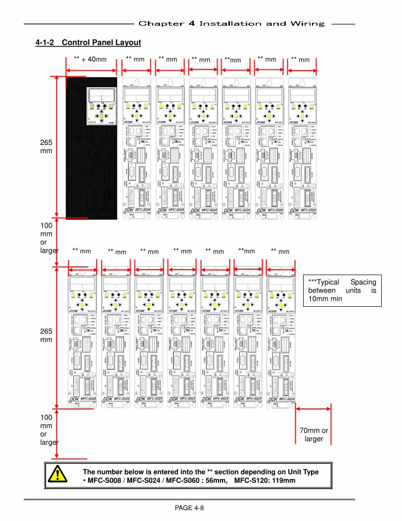
Chapter 4 Installation and Wiring
PAGE 4-8
4-1-2 Control Panel Layout
The number below is entered into the ** section depending on Unit Type
・・・・MFC-S008 / MFC-S024 / MFC-S060 : 56mm, MFC-S120: 119mm
** + 40mm ** mm ** mm ** mm **mm ** mm ** mm
** mm ** mm ** mm ** mm ** mm **mm ** mm
100 mm or larger
265mm
265mm
100 mm or larger
70mm or larger
***Typical Spacing between units is 10mm min
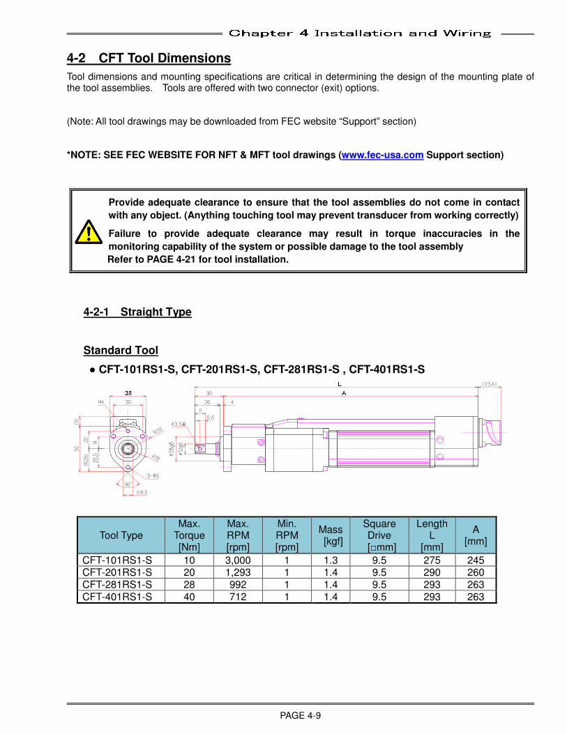
Chapter 4 Installation and Wiring
PAGE 4-9
4-2 CFT Tool Dimensions
Tool dimensions and mounting specifications are critical in determining the design of the mounting plate of the tool assemblies. Tools are offered with two connector (exit) options.
(Note: All tool drawings may be downloaded from FEC website “Support” section)
*NOTE: SEE FEC WEBSITE FOR NFT & MFT tool drawings (www.fec-usa.com Support section)
Provide adequate clearance to ensure that the tool assemblies do not come in contact
with any object. (Anything touching tool may prevent transducer from working correctly)
Failure to provide adequate clearance may result in torque inaccuracies in the
monitoring capability of the system or possible damage to the tool assembly
Refer to PAGE 4-21 for tool installation.
4-2-1 Straight Type
Standard Tool
● CFT-101RS1-S, CFT-201RS1-S, CFT-281RS1-S , CFT-401RS1-S
Tool Type Max.
Torque [Nm]
Max. RPM [rpm]
Min. RPM [rpm]
Mass [kgf]
Square Drive
[□mm]
Length L
[mm]
A [mm]
CFT-101RS1-S 10 3,000 1 1.3 9.5 275 245 CFT-201RS1-S 20 1,293 1 1.4 9.5 290 260 CFT-281RS1-S 28 992 1 1.4 9.5 293 263 CFT-401RS1-S 40 712 1 1.4 9.5 293 263
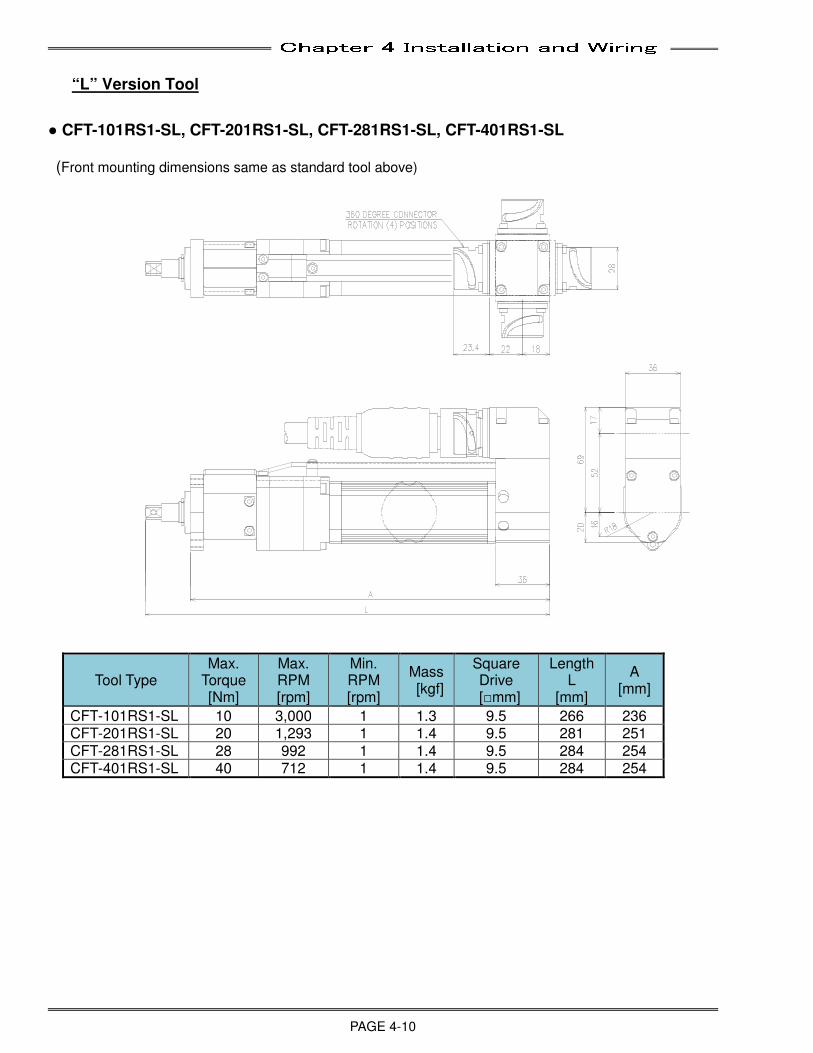
Chapter 4 Installation and Wiring
PAGE 4-10
“L” Version Tool
● CFT-101RS1-SL, CFT-201RS1-SL, CFT-281RS1-SL, CFT-401RS1-SL (Front mounting dimensions same as standard tool above)
Tool Type Max.
Torque [Nm]
Max. RPM [rpm]
Min. RPM [rpm]
Mass [kgf]
Square Drive
[□mm]
Length L
[mm]
A [mm]
CFT-101RS1-SL 10 3,000 1 1.3 9.5 266 236 CFT-201RS1-SL 20 1,293 1 1.4 9.5 281 251 CFT-281RS1-SL 28 992 1 1.4 9.5 284 254 CFT-401RS1-SL 40 712 1 1.4 9.5 284 254
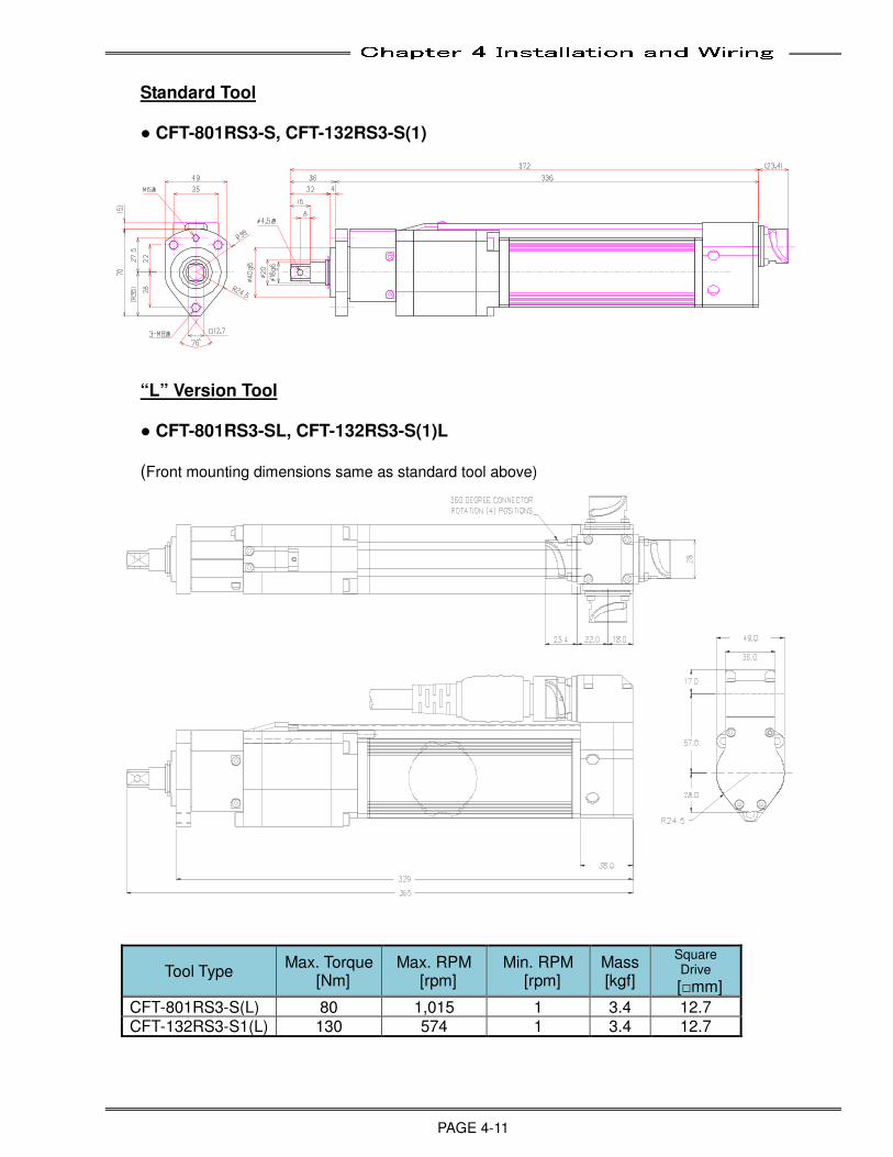
Chapter 4 Installation and Wiring
PAGE 4-11
Standard Tool ● CFT-801RS3-S, CFT-132RS3-S(1)
“L” Version Tool ● CFT-801RS3-SL, CFT-132RS3-S(1)L
(Front mounting dimensions same as standard tool above)
Tool Type Max. Torque
[Nm] Max. RPM
[rpm] Min. RPM
[rpm] Mass [kgf]
Square Drive
[□mm]
CFT-801RS3-S(L) 80 1,015 1 3.4 12.7 CFT-132RS3-S1(L) 130 574 1 3.4 12.7
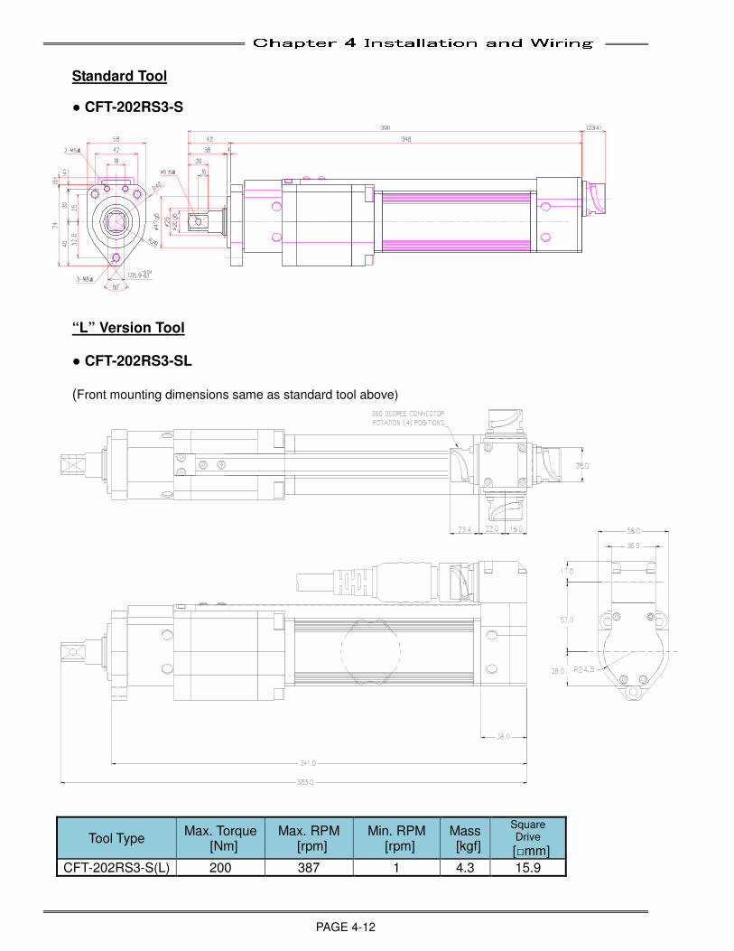
Chapter 4 Installation and Wiring
PAGE 4-12
Standard Tool
● CFT-202RS3-S
“L” Version Tool ● CFT-202RS3-SL
(Front mounting dimensions same as standard tool above)
Tool Type Max. Torque
[Nm] Max. RPM
[rpm] Min. RPM
[rpm] Mass [kgf]
Square Drive
[□mm]
CFT-202RS3-S(L) 200 387 1 4.3 15.9
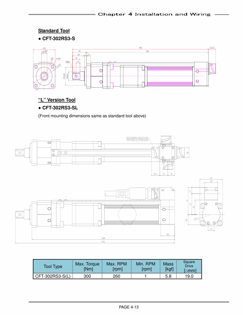
Chapter 4 Installation and Wiring
PAGE 4-13
Standard Tool
● CFT-302RS3-S
“L” Version Tool
● CFT-302RS3-SL
(Front mounting dimensions same as standard tool above)
Tool Type Max. Torque
[Nm] Max. RPM
[rpm] Min. RPM
[rpm] Mass [kgf]
Square Drive
[□mm]
CFT-302RS3-S(L) 300 260 1 5.8 19.0
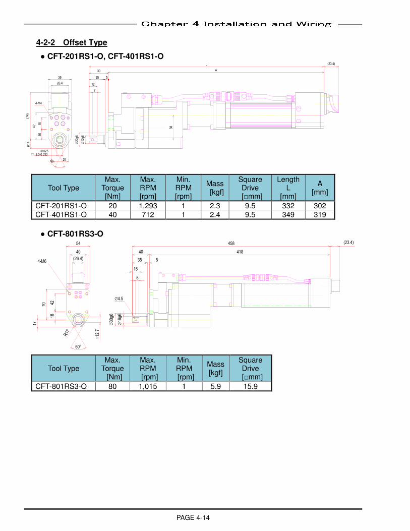
Chapter 4 Installation and Wiring
PAGE 4-14
4-2-2 Offset Type
● CFT-201RS1-O, CFT-401RS1-O
Tool Type Max.
Torque [Nm]
Max. RPM [rpm]
Min. RPM [rpm]
Mass [kgf]
Square Drive
[□mm]
Length L
[mm]
A [mm]
CFT-201RS1-O 20 1,293 1 2.3 9.5 332 302 CFT-401RS1-O 40 712 1 2.4 9.5 349 319
● CFT-801RS3-O
Tool Type Max.
Torque [Nm]
Max. RPM
[rpm]
Min. RPM
[rpm]
Mass [kgf]
Square Drive
[□mm]
CFT-801RS3-O 80 1,015 1 5.9 15.9
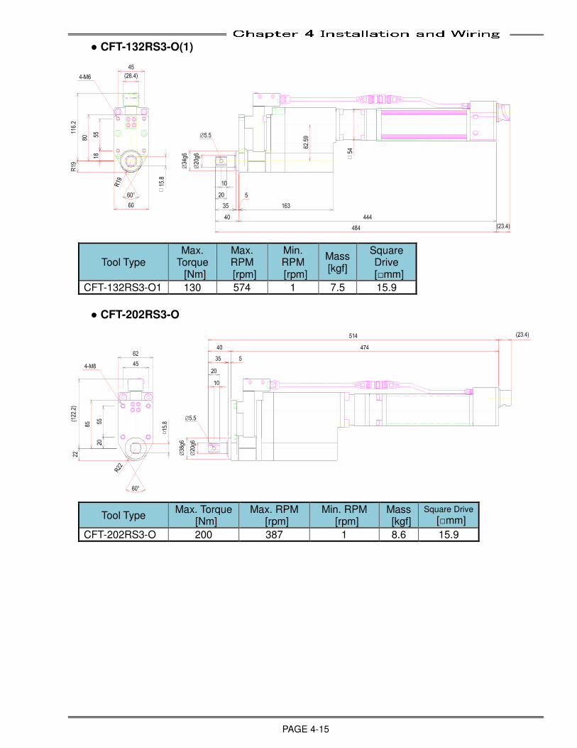
Chapter 4 Installation and Wiring
PAGE 4-15
● CFT-132RS3-O(1)
Tool Type Max.
Torque [Nm]
Max. RPM
[rpm]
Min. RPM
[rpm]
Mass [kgf]
Square Drive
[□mm]
CFT-132RS3-O1 130 574 1 7.5 15.9
● CFT-202RS3-O
Tool Type Max. Torque
[Nm] Max. RPM
[rpm] Min. RPM
[rpm] Mass [kgf]
Square Drive
[□mm]
CFT-202RS3-O 200 387 1 8.6 15.9
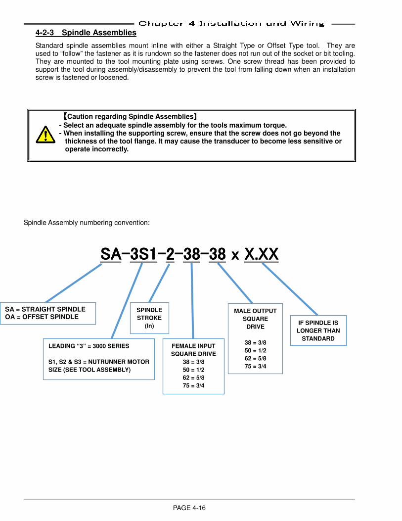
Chapter 4 Installation and Wiring
PAGE 4-16
4-2-3 Spindle Assemblies
Standard spindle assemblies mount inline with either a Straight Type or Offset Type tool. They are used to “follow” the fastener as it is rundown so the fastener does not run out of the socket or bit tooling. They are mounted to the tool mounting plate using screws. One screw thread has been provided to support the tool during assembly/disassembly to prevent the tool from falling down when an installation screw is fastened or loosened.
【【【【Caution regarding Spindle Assemblies】】】】
- Select an adequate spindle assembly for the tools maximum torque. - When installing the supporting screw, ensure that the screw does not go beyond the
thickness of the tool flange. It may cause the transducer to become less sensitive or operate incorrectly.
Spindle Assembly numbering convention:
SASASASA----3S13S13S13S1----2222----38383838----38383838 x x x x X.XXX.XXX.XXX.XX
SA = STRAIGHT SPINDLE OA = OFFSET SPINDLE
LEADING “3” = 3000 SERIES
S1, S2 & S3 = NUTRUNNER MOTOR
SIZE (SEE TOOL ASSEMBLY)
FEMALE INPUT
SQUARE DRIVE
38 = 3/8
50 = 1/2
62 = 5/8
75 = 3/4
SPINDLE
STROKE
(In)
MALE OUTPUT
SQUARE
DRIVE
38 = 3/8
50 = 1/2
62 = 5/8
75 = 3/4
IF SPINDLE IS
LONGER THAN
STANDARD
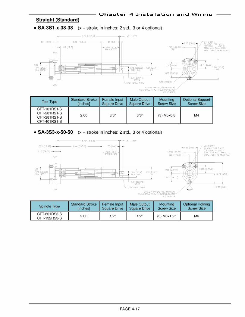
Chapter 4 Installation and Wiring
PAGE 4-17
Straight (Standard)
● SA-3S1-x-38-38 (x = stroke in inches: 2 std., 3 or 4 optional)
Tool Type Standard Stroke
[inches] Female Input Square Drive
Male Output Square Drive
Mounting Screw Size
Optional Support Screw Size
CFT-101RS1-S CFT-201RS1-S CFT-281RS1-S CFT-401RS1-S
2.00 3/8” 3/8” (3) M5x0.8 M4
● SA-3S3-x-50-50 (x = stroke in inches: 2 std., 3 or 4 optional)
Spindle Type Standard Stroke
[inches] Female Input Square Drive
Male Output Square Drive
Mounting Screw Size
Optional Holding Screw Size
CFT-801RS3-S CFT-132RS3-S
2.00 1/2” 1/2” (3) M8x1.25 M6
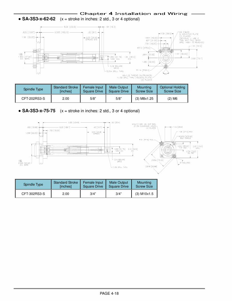
Chapter 4 Installation and Wiring
PAGE 4-18
● SA-3S3-x-62-62 (x = stroke in inches: 2 std., 3 or 4 optional)
Spindle Type Standard Stroke
[inches] Female Input Square Drive
Male Output Square Drive
Mounting Screw Size
Optional Holding Screw Size
CFT-202RS3-S 2.00 5/8” 5/8” (3) M8x1.25 (2) M6
● SA-3S3-x-75-75 (x = stroke in inches: 2 std., 3 or 4 optional)
Spindle Type Standard Stroke
[inches] Female Input Square Drive
Male Output Square Drive
Mounting Screw Size
CFT-302RS3-S 2.00 3/4” 3/4” (3) M10x1.5
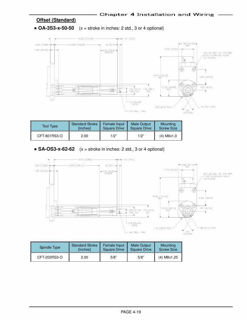
Chapter 4 Installation and Wiring
PAGE 4-19
Offset (Standard)
● OA-3S3-x-50-50 (x = stroke in inches: 2 std., 3 or 4 optional)
Tool Type Standard Stroke
[inches] Female Input Square Drive
Male Output Square Drive
Mounting Screw Size
CFT-801RS3-O 2.00 1/2” 1/2” (4) M8x1.0
● SA-OS3-x-62-62 (x = stroke in inches: 2 std., 3 or 4 optional)
Spindle Type Standard Stroke
[inches] Female Input Square Drive
Male Output Square Drive
Mounting Screw Size
CFT-202RS3-O 2.00 5/8” 5/8” (4) M8x1.25
Chapter 4 Installation and Wiring
PAGE 4-20
4-2-4 Mounting Plate Design Requirements
The plate to which the tools are mounted must maintain the following specifications:
Plate must be Blanchard ground (to ensure sides are adequately flat and parallel) to a minimum thickness of 15.88 mm (.625 inch) +/- .05 mm (.002 inch).
Chamfer all bores on both sides by 1.6 mm (.063 inch) x 45 degrees.
Tools must be mounted 1.6 mm (.063 inch) apart, at a minimum.
4-2-5 Locating Procedure for Fixtured Multi Spindle Powerhead
1. The locating of multi-spindle fastening equipment begins with a review of the floor layout and assembly drawings. They must be checked for set-up dimensions and any special instructions. Once the proper dimensions have been established, installation may proceed.
2. Verify the established dimensions of each of the following in order of precedence:
Conveyor - Whether this is new or existing machinery, this MUST be done first. Adjust to print as required. NOTE 1 Pallet - Verify using several pallets. Make note of any variation for further alignment. Machine base - Set base height and location while maintaining parallelism to the conveyor
NOTE 1: If any dimensions do not match the prints or is severely out of adjustment, evaluate the effect of the discrepancy prior to proceeding. Document any variations from print.
3. Once the conveyor, pallet and machine base are set to dimensions and level, the fastening equipment can be installed. The head, fastening tools and spindle assemblies must be assembled and secured to the slide assembly prior to locating the powerhead to the work piece. If push pull blocks are not used to locate the powerhead to the slide, dowel pins should be install at this point
4. When locating the power head to the work piece, ensure that the work piece is located as it will be during actual production. EXAMPLE: if there is a pallet locate and clamp, it must be in the clamp position). Fasteners should be rundown fully to ensure that the alignment is perform with the fasteners in their final fixed positions.
5. Next you should advance the power head slowly to check the alignment to the work piece. If there is a misalignment left to right or up and down, the base must be moved using the leveling jack screws, push pull blocks or provided spacers. The powerhead may be adjusted on the slide assembly if push pull blocks have been utilized. Do not readjust the conveyor or the pallets.
6. When adjusting the alignment by moving the machine base left to right or up and down, the base must remain parallel to the conveyor. Alignment is correct when all spindles, easily slip on and off of all the fasteners, without causing any sticking, cocking or undue stress on the fasteners. This must be performed on several work pieces and pallets to ensure correct alignment.
7. Once the alignment has been accomplished, adjustment of slide stops, shock absorbers and flow controls must be done. Adjust the slide advance stops for 3/8" minimum spring preload on the spindles when the fastener is secure (Refer to assembly drawing). Ensure that the spindle assembly does not fully compress during any phase of the powerhead advance.
Setting of the flow controls is done with cycle time in mind. The speed of the slides should be set at a smooth and even movement. The cylinder cushions and shock absorbers, if provided, should be set to avoid any slamming at the end of the stroke.
8. When everything has been aligned and adjusted they should be locked down, tightened up and anchored.
NOTE: Some of the locating equipment that can be used to install a fastening system may include a precision level, indicators with magnetic base, a conventional transit or laser transit.
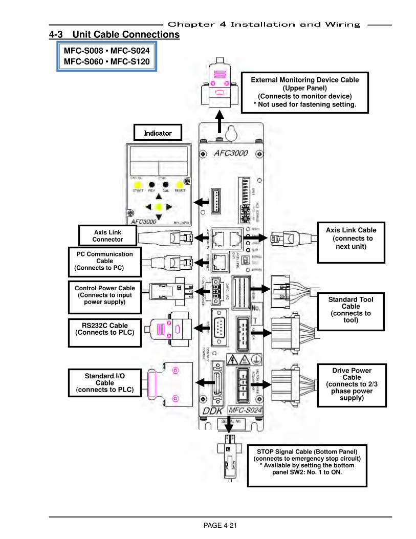
Chapter 4 Installation and Wiring
PAGE 4-21
4-3 Unit Cable Connections
MFC-S008・・・・MFC-S024
MFC-S060・・・・MFC-S120
STOP Signal Cable (Bottom Panel) (connects to emergency stop circuit)
* Available by setting the bottom panel SW2: No. 1 to ON.
Standard I/O Cable
(connects to PLC)
External Monitoring Device Cable
(Upper Panel)
(Connects to monitor device)
* Not used for fastening setting.
Control Power Cable (Connects to input
power supply)
RS232C Cable (Connects to PLC)
PC Communication Cable
(Connects to PC)
Axis Link Cable
(connects to
next unit)
Standard Tool Cable
(connects to tool)
Drive Power Cable
(connects to 2/3 phase power
supply)
IndicatorIndicatorIndicatorIndicator Axis Link
Connector
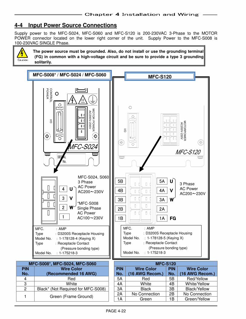
Chapter 4 Installation and Wiring
PAGE 4-22
4-4 Input Power Source Connections
Supply power to the MFC-S024, MFC-S060 and MFC-S120 is 200-230VAC 3-Phase to the MOTOR POWER connector located on the lower right corner of the unit. Supply Power to the MFC-S008 is 100-230VAC SINGLE Phase.
The power source must be grounded. Also, do not install or use the grounding terminal
(FG) in common with a high-voltage circuit and be sure to provide a type 3 grounding
solitarily.
MFC-S008*, MFC-S024, MFC-S060 MFC-S120 PIN No.
Wire Color (Recommended 16 AWG)
PIN No.
Wire Color (16 AWG Recom.)
PIN No.
Wire Color (16 AWG Recom.)
4 Red 5A Red 5B Red/Yellow 3 White 4A White 4B White/Yellow 2 Black* (Not Required for MFC-S008) 3A Black 3B Black/Yellow
1 Green (Frame Ground) 2A No Connection 2B No Connection 1A Green 1B Green/Yellow
MFC. :AMP
Type :D3200S Receptacle Housing
Model No. :1-178128-4 (Keying X)
Type :Receptacle Contact
(Pressure bonding type)
Model No. :1-175218-3
MFC-S008* / MFC-S024 / MFC-S060
4 UUUU
3 VVVV
2 WWWW
1
P
OW
ER
I/O
MO
TO
RA
C200V
-230V
MFC-S120
5A UUUU
4A VVVV
3A WWWW
2A
1A FGFGFGFG
3 Phase
AC Power
AC200~230V
MFC. :AMP
Type :D3200S Receptacle Housing
Model No. :1-178128-5 (Keying X)
Type :Receptacle Contact
(Pressure bonding type)
Model No. :1-175218-3
5B
4B
3B
2B
1B
MFC-S024, S060
3 Phase
AC Power
AC200~230V
Caution
*MFC-S008
Single Phase
AC Power
AC100~230V
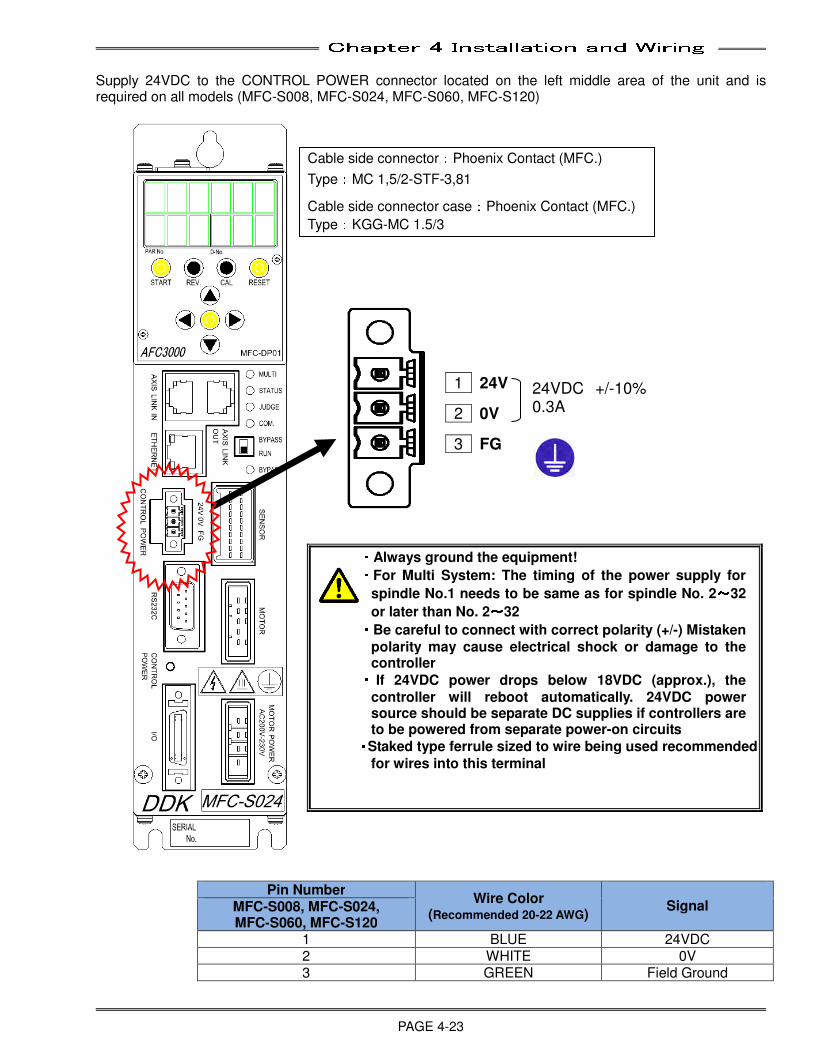
Chapter 4 Installation and Wiring
PAGE 4-23
Supply 24VDC to the CONTROL POWER connector located on the left middle area of the unit and is required on all models (MFC-S008, MFC-S024, MFC-S060, MFC-S120)
・・・・Always ground the equipment! ・・・・For Multi System: The timing of the power supply for
spindle No.1 needs to be same as for spindle No. 2~~~~32
or later than No. 2~~~~32 ・・・・Be careful to connect with correct polarity (+/-) Mistaken
polarity may cause electrical shock or damage to the controller ・・・・ If 24VDC power drops below 18VDC (approx.), the
controller will reboot automatically. 24VDC power source should be separate DC supplies if controllers are to be powered from separate power-on circuits
・・・・Staked type ferrule sized to wire being used recommended
for wires into this terminal
Pin Number Wire Color
(Recommended 20-22 AWG) Signal
MFC-S008, MFC-S024, MFC-S060, MFC-S120
1 BLUE 24VDC 2 WHITE 0V 3 GREEN Field Ground
Cable side connector:Phoenix Contact (MFC.)
Type:MC 1,5/2-STF-3,81
Cable side connector case:Phoenix Contact (MFC.)
Type:KGG-MC 1.5/3
1 24V
2 0V
3 FG
24VDC +/-10% 0.3A
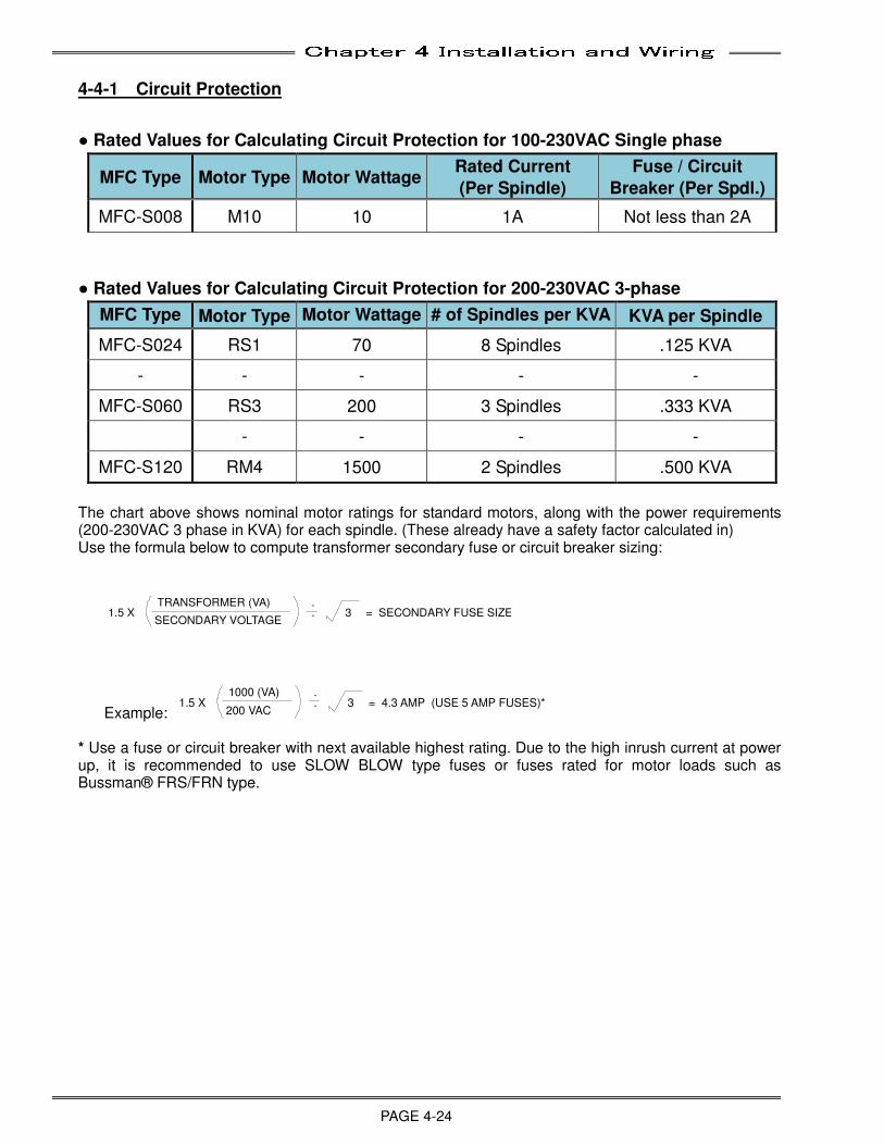
Chapter 4 Installation and Wiring
PAGE 4-24
4-4-1 Circuit Protection
● Rated Values for Calculating Circuit Protection for 100-230VAC Single phase
MFC Type Motor Type Motor Wattage Rated Current
(Per Spindle)
Fuse / Circuit
Breaker (Per Spdl.)
MFC-S008 M10 10 1A Not less than 2A
● Rated Values for Calculating Circuit Protection for 200-230VAC 3-phase
MFC Type Motor Type Motor Wattage # of Spindles per KVA KVA per Spindle
MFC-S024 RS1 70 8 Spindles .125 KVA
- - - - -
MFC-S060 RS3 200 3 Spindles .333 KVA
- - - -
MFC-S120 RM4 1500 2 Spindles .500 KVA The chart above shows nominal motor ratings for standard motors, along with the power requirements (200-230VAC 3 phase in KVA) for each spindle. (These already have a safety factor calculated in) Use the formula below to compute transformer secondary fuse or circuit breaker sizing:
1.5 XTRANSFORMER (VA)
SECONDARY VOLTAGE
.
. 3 = SECONDARY FUSE SIZE
Example: 1.5 X
1000 (VA)
200 VAC
.
. 3 = 4.3 AMP (USE 5 AMP FUSES)*
* Use a fuse or circuit breaker with next available highest rating. Due to the high inrush current at power up, it is recommended to use SLOW BLOW type fuses or fuses rated for motor loads such as Bussman® FRS/FRN type.

Chapter 4 Installation and Wiring
PAGE 4-25
4-5 Tool Wiring and Installation
4-5-1 Tool Installation Procedures
Avoid mechanical contact on the TOOL Unit main body.
_ Contact between tools.
_ Jammed or pinched cables.
_ Improper installing position (methods).
Secure the tool on the tool installation plate with a bolt.
Mechanical contact may cause unstable torque accuracy, it may cause mechanical damage such as bolt fracture.
The tool must be mounted from the front mounting bolt pattern for proper operation.
Proper Installation Improper Installation
【【【【Caution regarding installation】】】】 ・・・・Large torque is applied when the tool is fastening and the same amount of
torque is applied to the tool connection parts. Therefore, the tool should be fixed on the proper locations and the specified mounting screws should be used. ・・・・Do NOT apply strong shock or force to a tool or damage may occur (Due to
sensitive parts) ・・・・Use cylinder cushions or shock absorbers to decelerate the tool head motions
and prevent excessive vibration, especially in short cycle time applications operating at high speeds. Repeated shock (overtime) could damage a tool.
Tool Mounting cannot be fixed to main body
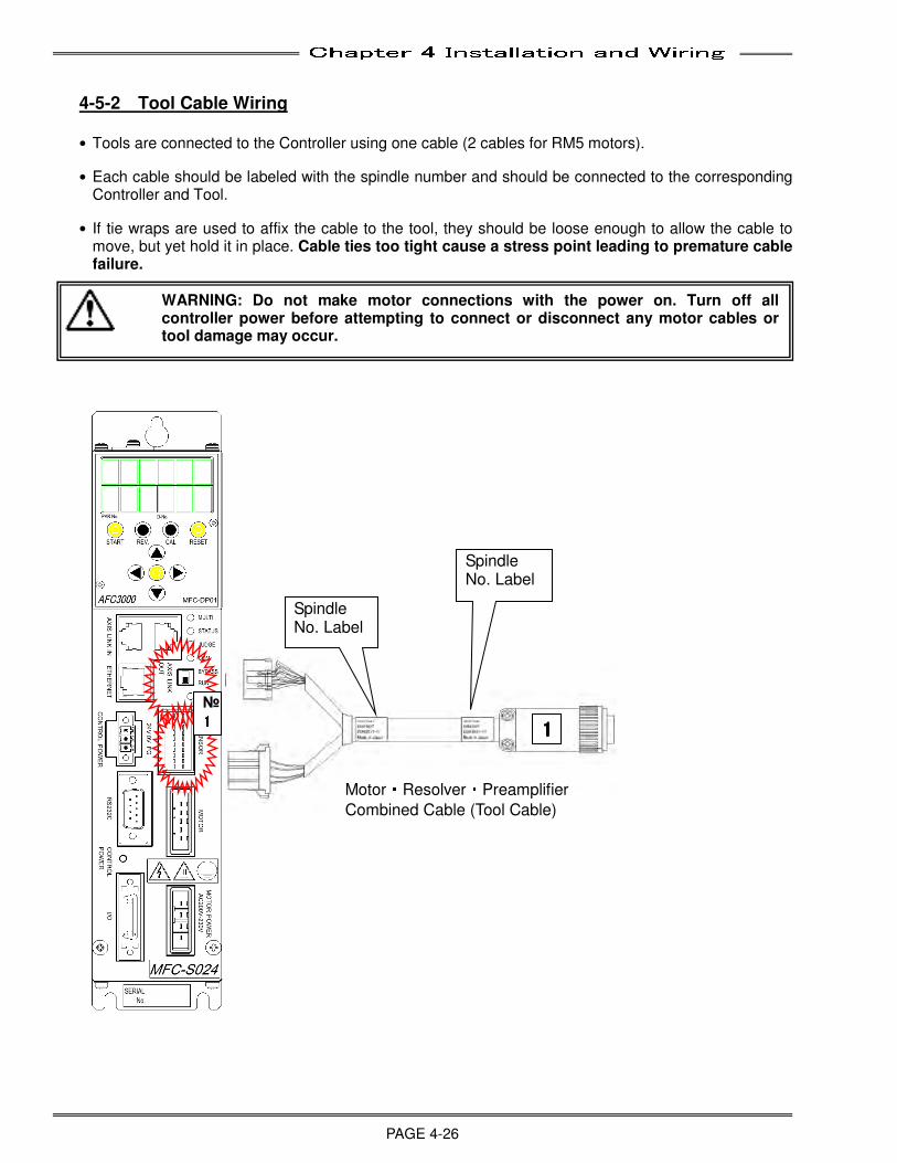
Chapter 4 Installation and Wiring
PAGE 4-26
4-5-2 Tool Cable Wiring
• Tools are connected to the Controller using one cable (2 cables for RM5 motors).
• Each cable should be labeled with the spindle number and should be connected to the corresponding Controller and Tool.
• If tie wraps are used to affix the cable to the tool, they should be loose enough to allow the cable to move, but yet hold it in place. Cable ties too tight cause a stress point leading to premature cable failure.
1111
Spindle No. Label
Spindle No. Label
Motor・Resolver・Preamplifier
Combined Cable (Tool Cable)
№ 1111
WARNING: Do not make motor connections with the power on. Turn off all controller power before attempting to connect or disconnect any motor cables or tool damage may occur.
Chapter 4 Installation and Wiring
PAGE 4-27
4-5-3 Cable Installation Guidelines
Improper installation of cables can reduce cable life expectancy drastically. The following guidelines should be used when installing cables.
• The cables must be prepared for installation without twists, bends or kinks. Upon unpacking the cables, any tie wraps used in shipping should be removed.
• Before inserting the cables in the cable tray, cable track or other overhead suspension, it is important that the cables be laid out or hung prior to installation long enough to relax any stresses and remove any “memory” resulting from packaging, transit or storage. If the cables cannot be relaxed, they should be shook out by grasping the cable length at its mid point and shaking the cables as you move to each end. Then, wrap the end of each cable with masking tape and make alignment marks on the top of each end. Maintain this alignment throughout the installation to assure cable is not being twisted.
• The minimum recommended bending radius of the cable should not be exceeded. When otherwise not specified, the minimum bend radius can be [generally] calculated by multiplying the cable’s outer diameter by ten (Rmin = O.D. x 10). When multiple cables are run together, the largest diameter cable in the bundle should be used for calculating bend radius. Minimum bend radius must be increased when repeated flexing occurs at a given point on the cables.
• Use the most direct path when routing cables.
• Do not weave cables between or wrap around one another.
• Route cables and connectors away from liquid of any type.
• Protect cable connectors from any impact or abrasion that may cause damage (IE: pulling cables through cable tray and dropping cables to the floor).
• Check cable route for possible chafing or abrasion points. Re-route or protect cable at these points with a nylon cable wrap or similar means to avoid future cable damage.
• The use of plastic cable ties (ty-wraps) should be avoided if possible. The use of Velcro straps is preferable. If the use of plastic cable ties cannot be avoided, the following practices should be followed:
o Cables should not be tied so tight as to cause indentations in the cable jacket. Flexible cables are designed to move inside their cable jacket. If this movement is restricted, wires in the cable may become stressed and break.
o Plastic cable ties around grouped cables should be used minimally so that cables have the ability to move individually rather than all as one.
o An acceptable method is to include the use of a flexible tubing or sleeve between the plastic cable tie and the cable(s).
• Do not tie or hang anything, whatsoever, from tool cables.
• Avoid running cables directly next to high voltage or high frequency lines.
• Cables must be supported near connectors in panel and at tool to avoid strain on connection points.
• Certain tool operations may have foreseeable cable damaging aspects which are unavoidable. In these situations a shorter “extension” cable can be provided with the expectation of replacing this intermediate, less expensive cable as required. The use and proper placement of an “extension” cable will also make cable replacement less time consuming.
Chapter 4 Installation and Wiring
PAGE 4-28
4-5-4 Considerations for Cable Trolleys
• Cables hung by festooning type systems must be secured to the individual cable trolley and positioned to avoid sharp bends and eliminate or minimize any torsion twisting.
• Restraint cords should be used in between cable trolleys to limit movement and reduce the stress on cables as they are extended. Restraint cord lengths must always be shorter than the length of cable hung between trolleys.
• Cable loops should be consistent in length, typically not exceeding 5 feet in depth between trolleys. Sufficient number of trolleys should be used in a system to support the entire length of moving cable and to allow relaxed stacking/festooning of cable loops when tool is in the retracted position.
• One trolley should be fixed to the runway rail to eliminate tugging on or stretching of cables.
4-5-5 Considerations for Flexible Cable Tracks
• Cables must under no circumstances have the opportunity to tangle. Therefore, the clearance height of a track compartment with several similar cables next to one another must not amount to more than one and a half times the cable diameter.
• There should be an “all around” minimum clearance between cables of 10% of the cable’s diameter.
• Cables and hoses with very different diameters should be laid separately. Separation is achieved by using Flexible Track separators. The following rules should be followed for cable separation:
o If (Cable 1 Diameter) + (Cable 2 Diameter) > 1.2 x Track Inner Height, then no separation is necessary.
o If (Cable 1 Diameter) + (Cable 2 Diameter) ≤ 1.2 x Track Inner Height, then a horizontal or vertical separator must be used to reduce the inner height, thereby preventing the entanglement of the cables.
• The cable weight should be symmetrically distributed along the width of the track.
• Cables must be able to move freely along the radius.
• The cables must be secured with strain relief at both ends. In exceptional cases, the cables may be fixed with strain relief at the moving end only. Unless using a Flexible Cable Track with integrated strain relief, a gap of 10~30 x cable diameter between the end of the bending segment and the fixed point is recommended for most cables. Under no circumstances should excess cable be put into a Flexible Cable Track.
• When installing cables into cable track, open one side of track and lay cables into track to avoid any twisting of the cable during the installation process. Do not ‘thread’ cable thru the cable track cable opening (without opening one side) as cable twisting may be induced by this process.
4-5-6 Considerations for Cable Trays & Ladders
• Cable drop out panels should be used where cables enter and exit a tray or ladder system. Sharp bends need to be avoided whenever possible.
• Cables should be secured at both entry and exit points of a tray or ladder.
• Avoid running high voltage or high frequency cables in the same tray or ladder as signal or control cables unless cables are designed for such environments.
• If excess cable is to be stored in a tray or ladder, do not tightly coil cable. Cable should be laid in as large of a loop as possible.
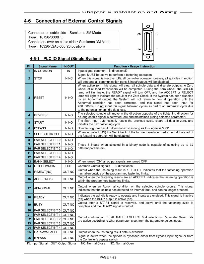
Chapter 4 Installation and Wiring
PAGE 4-29
4-6 Connection of External Control Signals
4-6-1 PLC IO Signal (Single System)
IN: Input Signal OUT: Output Signal NC: Normal Close NO: Normal Open
Pin Signal Name IN/OUT Function・・・・Usage Instruction
1 IN COMMON IN Input signal common(Bi-directional)
2 STOP IN NC
Signal MUST be active to perform a fastening operation. When this signal is inactive (off), all controller operation ceases, all spindles in motion will stop and all communication ports & input/outputs will be disabled.
3 RESET IN NO
When active (on), this signal will clear all spindle data and discrete outputs. A Zero Check of all load transducers will be completed. During the Zero Check, the CHECK lamp will illuminate, the READY signal will turn OFF, and the ACCEPT or REJECT lamp will light to indicate the result of the Zero Check. If the System has been disabled by an Abnormal output, the System will not return to normal operation until the Abnormal condition has been corrected, and this signal has been input for 200~500ms. Do not input this signal between cycles as part of an automatic cycle due to the potential for spindle data loss.
4 REVERSE IN NO The selected spindle will move in the direction opposite of the tightening direction for as long as this signal is activated (on) and maintained (using selected parameter)
5 START IN NO The Start input automatically resets the previous cycle, clears all data to zero, and initiates the next fastening cycle.
6 BYPASS IN NO Spindle is ignored as if it does not exist as long as this signal is "ON"
7 SELF CHECK OFF IN NO When activated (ON) the Self Check of the torque transducer performed at the start of the fastening operation will be disabled.
8 PAR SELECT BIT 0 IN NO
These 5 inputs when selected in a binary code is capable of selecting up to 32 different parameters.
9 PAR SELECT BIT 1 IN NO
10 PAR SELECT BIT 2 IN NO
11 PAR SELECT BIT 3 IN NO
12 PAR SELECT BIT 4 IN NO
13 BANK SELECT IN NO When turned “ON” all output signals are turned OFF.
14 OUT COMMON OUT Common Output signals (Bi-directional)
15 REJECT(NG) OUT NO Output when the fastening result is a REJECT. Indicates that the fastening operation has fallen outside of the programmed fastening limits.
16 ACCEPT(OK) OUT NO Output when the fastening results are an ACCEPT. Indicates the fastening operation is within the programmed fastening limits.
17 ABNORMAL OUT NO Output when an Abnormal condition on the selected spindle occurs. This signal indicates that the spindle has detected an internal fault, and can no longer proceed.
18 READY OUT NO Indicates the spindle is ready to operate and inputs are enabled. This signal is inactive (off) when the BUSY output is active (on).
19 BUSY OUT NO Output after a START signal is received, and active until the fastening cycle is complete and the READY signal is output.
20 PAR SELECT BIT 0 OUT NO
Output confirmation of PARAMETER SELECT 0~4 selections. Parameter Select bits are active according to what parameter is set from the parameter select inputs.
21 PAR SELECT BIT 1 OUT NO
22 PAR SELECT BIT 2 OUT NO
23 PAR SELECT BIT 3 OUT NO
24 PAR SELECT BIT 4 OUT NO
25 DATA AVAILABLE OUT NO Output when the fastening result data is available.
26 BYPASS OUT NO Signal is active when the spindle is bypassed either from Bypass input signal or from the Controller’s bypass switch.
Connector on cable side:Sumitomo 3M Made
Type:10126-3000PE
Connector cover on cable side:Sumitomo 3M Made
Type:10326-52A0-008(26 position)
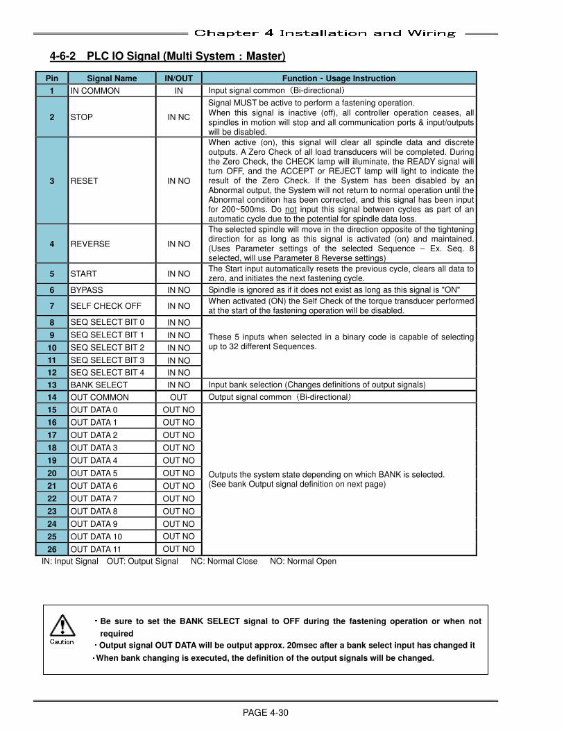
Chapter 4 Installation and Wiring
PAGE 4-30
4-6-2 PLC IO Signal (Multi System::::Master)
IN: Input Signal OUT: Output Signal NC: Normal Close NO: Normal Open
Pin Signal Name IN/OUT Function・・・・Usage Instruction
1 IN COMMON IN Input signal common(Bi-directional)
2 STOP IN NC
Signal MUST be active to perform a fastening operation.
When this signal is inactive (off), all controller operation ceases, all spindles in motion will stop and all communication ports & input/outputs will be disabled.
3 RESET IN NO
When active (on), this signal will clear all spindle data and discrete outputs. A Zero Check of all load transducers will be completed. During the Zero Check, the CHECK lamp will illuminate, the READY signal will turn OFF, and the ACCEPT or REJECT lamp will light to indicate the result of the Zero Check. If the System has been disabled by an Abnormal output, the System will not return to normal operation until the Abnormal condition has been corrected, and this signal has been input for 200~500ms. Do not input this signal between cycles as part of an automatic cycle due to the potential for spindle data loss.
4 REVERSE IN NO
The selected spindle will move in the direction opposite of the tightening direction for as long as this signal is activated (on) and maintained. (Uses Parameter settings of the selected Sequence – Ex. Seq. 8 selected, will use Parameter 8 Reverse settings)
5 START IN NO The Start input automatically resets the previous cycle, clears all data to zero, and initiates the next fastening cycle.
6 BYPASS IN NO Spindle is ignored as if it does not exist as long as this signal is "ON"
7 SELF CHECK OFF IN NO When activated (ON) the Self Check of the torque transducer performed at the start of the fastening operation will be disabled.
8 SEQ SELECT BIT 0 IN NO
These 5 inputs when selected in a binary code is capable of selecting up to 32 different Sequences.
9 SEQ SELECT BIT 1 IN NO
10 SEQ SELECT BIT 2 IN NO
11 SEQ SELECT BIT 3 IN NO
12 SEQ SELECT BIT 4 IN NO
13 BANK SELECT IN NO Input bank selection (Changes definitions of output signals)
14 OUT COMMON OUT Output signal common(Bi-directional)
15 OUT DATA 0 OUT NO
Outputs the system state depending on which BANK is selected. (See bank Output signal definition on next page)
16 OUT DATA 1 OUT NO
17 OUT DATA 2 OUT NO
18 OUT DATA 3 OUT NO
19 OUT DATA 4 OUT NO
20 OUT DATA 5 OUT NO
21 OUT DATA 6 OUT NO
22 OUT DATA 7 OUT NO
23 OUT DATA 8 OUT NO
24 OUT DATA 9 OUT NO
25 OUT DATA 10 OUT NO
26 OUT DATA 11 OUT NO
・・・・ Be sure to set the BANK SELECT signal to OFF during the fastening operation or when not
required ・・・・ Output signal OUT DATA will be output approx. 20msec after a bank select input has changed it
・・・・When bank changing is executed, the definition of the output signals will be changed.
Caution
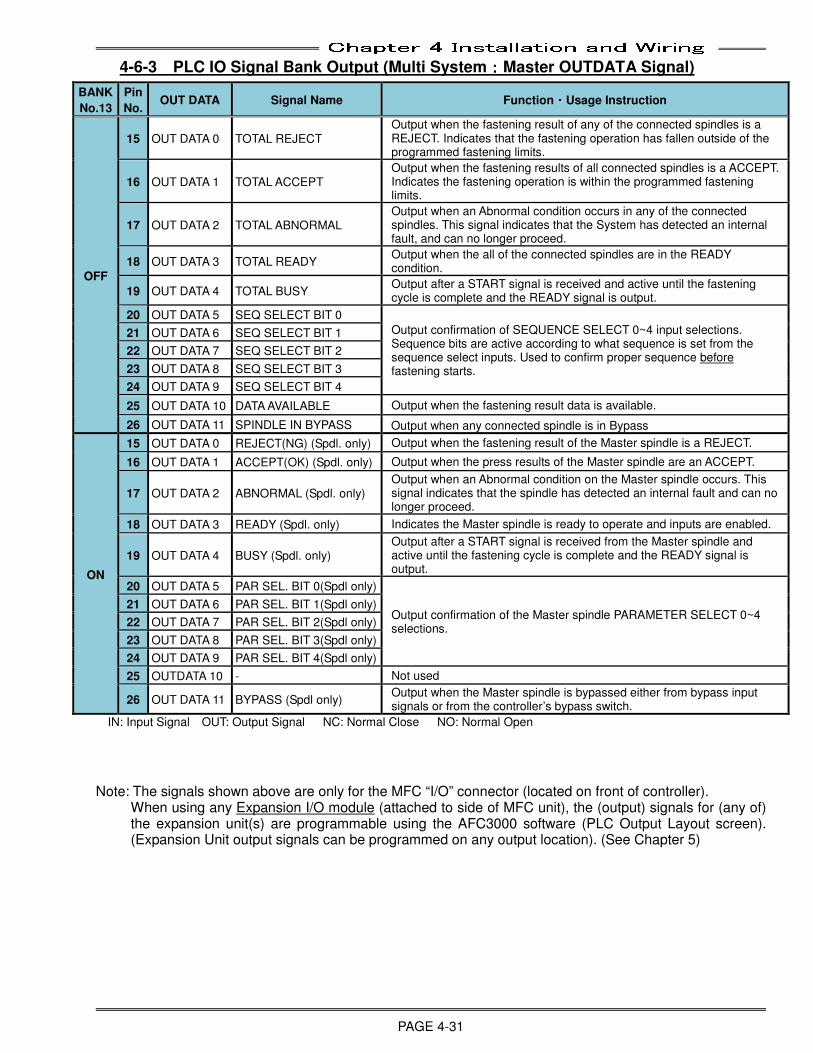
Chapter 4 Installation and Wiring
PAGE 4-31
4-6-3 PLC IO Signal Bank Output (Multi System::::Master OUTDATA Signal)
IN: Input Signal OUT: Output Signal NC: Normal Close NO: Normal Open Note: The signals shown above are only for the MFC “I/O” connector (located on front of controller).
When using any Expansion I/O module (attached to side of MFC unit), the (output) signals for (any of) the expansion unit(s) are programmable using the AFC3000 software (PLC Output Layout screen). (Expansion Unit output signals can be programmed on any output location). (See Chapter 5)
BANK
No.13
Pin
No. OUT DATA Signal Name Function・・・・Usage Instruction
OFF
15 OUT DATA 0 TOTAL REJECT
Output when the fastening result of any of the connected spindles is a REJECT. Indicates that the fastening operation has fallen outside of the programmed fastening limits.
16 OUT DATA 1 TOTAL ACCEPT Output when the fastening results of all connected spindles is a ACCEPT. Indicates the fastening operation is within the programmed fastening limits.
17 OUT DATA 2 TOTAL ABNORMAL Output when an Abnormal condition occurs in any of the connected spindles. This signal indicates that the System has detected an internal fault, and can no longer proceed.
18 OUT DATA 3 TOTAL READY Output when the all of the connected spindles are in the READY condition.
19 OUT DATA 4 TOTAL BUSY Output after a START signal is received and active until the fastening cycle is complete and the READY signal is output.
20 OUT DATA 5 SEQ SELECT BIT 0
Output confirmation of SEQUENCE SELECT 0~4 input selections. Sequence bits are active according to what sequence is set from the sequence select inputs. Used to confirm proper sequence before fastening starts.
21 OUT DATA 6 SEQ SELECT BIT 1
22 OUT DATA 7 SEQ SELECT BIT 2
23 OUT DATA 8 SEQ SELECT BIT 3
24 OUT DATA 9 SEQ SELECT BIT 4
25 OUT DATA 10 DATA AVAILABLE Output when the fastening result data is available.
26 OUT DATA 11 SPINDLE IN BYPASS Output when any connected spindle is in Bypass
ON
15 OUT DATA 0 REJECT(NG) (Spdl. only) Output when the fastening result of the Master spindle is a REJECT.
16 OUT DATA 1 ACCEPT(OK) (Spdl. only) Output when the press results of the Master spindle are an ACCEPT.
17 OUT DATA 2 ABNORMAL (Spdl. only) Output when an Abnormal condition on the Master spindle occurs. This signal indicates that the spindle has detected an internal fault and can no longer proceed.
18 OUT DATA 3 READY (Spdl. only) Indicates the Master spindle is ready to operate and inputs are enabled.
19 OUT DATA 4 BUSY (Spdl. only) Output after a START signal is received from the Master spindle and active until the fastening cycle is complete and the READY signal is output.
20 OUT DATA 5 PAR SEL. BIT 0(Spdl only)
Output confirmation of the Master spindle PARAMETER SELECT 0~4 selections.
21 OUT DATA 6 PAR SEL. BIT 1(Spdl only)
22 OUT DATA 7 PAR SEL. BIT 2(Spdl only)
23 OUT DATA 8 PAR SEL. BIT 3(Spdl only)
24 OUT DATA 9 PAR SEL. BIT 4(Spdl only)
25 OUTDATA 10 - Not used
26 OUT DATA 11 BYPASS (Spdl only) Output when the Master spindle is bypassed either from bypass input signals or from the controller’s bypass switch.
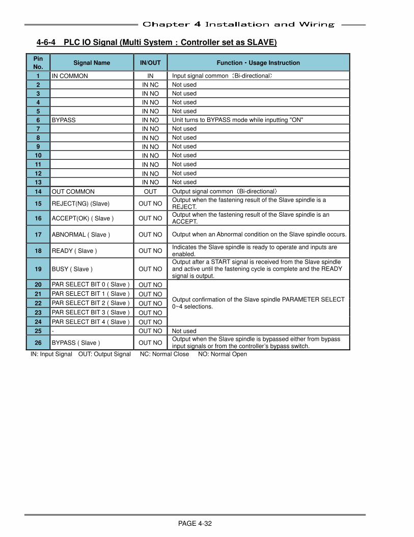
Chapter 4 Installation and Wiring
PAGE 4-32
4-6-4 PLC IO Signal (Multi System::::Controller set as SLAVE)
IN: Input Signal OUT: Output Signal NC: Normal Close NO: Normal Open
Pin
No. Signal Name IN/OUT Function・・・・Usage Instruction
1 IN COMMON IN Input signal common(Bi-directional)
2 IN NC Not used
3 IN NO Not used
4 IN NO Not used
5 IN NO Not used
6 BYPASS IN NO Unit turns to BYPASS mode while inputting "ON"
7 IN NO Not used
8 IN NO Not used
9 IN NO Not used
10 IN NO Not used
11 IN NO Not used
12 IN NO Not used
13 IN NO Not used
14 OUT COMMON OUT Output signal common(Bi-directional)
15 REJECT(NG) (Slave) OUT NO Output when the fastening result of the Slave spindle is a REJECT.
16 ACCEPT(OK) ( Slave ) OUT NO Output when the fastening result of the Slave spindle is an ACCEPT.
17 ABNORMAL ( Slave ) OUT NO Output when an Abnormal condition on the Slave spindle occurs.
18 READY ( Slave ) OUT NO Indicates the Slave spindle is ready to operate and inputs are enabled.
19 BUSY ( Slave ) OUT NO Output after a START signal is received from the Slave spindle and active until the fastening cycle is complete and the READY signal is output.
20 PAR SELECT BIT 0 ( Slave ) OUT NO
Output confirmation of the Slave spindle PARAMETER SELECT 0~4 selections.
21 PAR SELECT BIT 1 ( Slave ) OUT NO
22 PAR SELECT BIT 2 ( Slave ) OUT NO
23 PAR SELECT BIT 3 ( Slave ) OUT NO
24 PAR SELECT BIT 4 ( Slave ) OUT NO
25 - OUT NO Not used
26 BYPASS ( Slave ) OUT NO Output when the Slave spindle is bypassed either from bypass input signals or from the controller’s bypass switch.
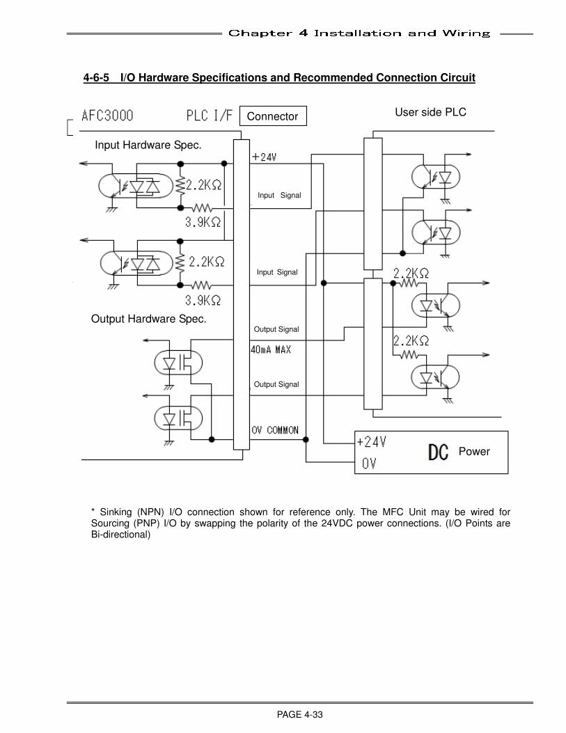
Chapter 4 Installation and Wiring
PAGE 4-33
4-6-5 I/O Hardware Specifications and Recommended Connection Circuit
出力ハードウェア仕様 2.2KΩ
AFC3000 ユーザー側 PLC
DC 電源
2.2KΩ
入力ハードウェア仕様
3.9KΩ
PLC I/F コネクタ出力信号** 40mA MAX 出力信号** OV COMMON
+24V
0V
入力信号** 入力信号** +24V
2.2KΩ
2.2KΩ
3.9KΩ
Input Signal
Input Signal
**
Output Signal
Connector User side PLC
Power
Output Hardware Spec.
Input Hardware Spec.
* Sinking (NPN) I/O connection shown for reference only. The MFC Unit may be wired for Sourcing (PNP) I/O by swapping the polarity of the 24VDC power connections. (I/O Points are Bi-directional)
Output Signal
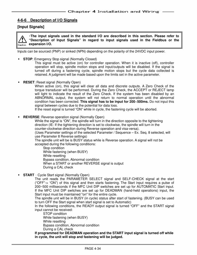
Chapter 4 Installation and Wiring
PAGE 4-34
4-6-6 Description of I/O Signals
[Input Signals]
Inputs can be sourced (PNP) or sinked (NPN) depending on the polarity of the 24VDC input power. STOP: Emergency Stop signal (Normally Closed)
This signal must be active (on) for controller operation. When it is inactive (off), controller operation will stop, spindle motion stops and input/outputs will be disabled. If the signal is turned off during a fastening cycle, spindle motion stops but the cycle data collected is retained. A judgment will be made based upon the limits set in the active parameter.
RESET: Reset signal (Normally Open) When active (on), this signal will clear all data and discrete outputs. A Zero Check of the torque transducer will be performed. During the Zero Check, the ACCEPT or REJECT lamp will light to indicate the result of the Zero Check. If the system has been disabled by an ABNORMAL output, the system will not return to normal operation until the abnormal condition has been corrected. This signal has to be input for 200~500ms. Do not input this signal between cycles due to the potential for data loss.
If the reset signal is turned “ON” while in cycle, the fastening cycle will be aborted.
REVERSE: Reverse operation signal (Normally Open) While the signal is “ON”, the spindle will turn in the direction opposite to the tightening direction (IE: If the tightening direction is set to clockwise, the spindle will turn in the counter-clockwise direction during Reverse operation and visa-versa). (Uses Parameter settings of the selected Parameter / Sequence – Ex. Seq. 8 selected, will use Parameter 8 Reverse settings) The spindle unit will be is BUSY status while is Reverse operation. A signal will not be accepted during the following conditions:
Stop condition While fastening (when BUSY) While resetting Bypass condition, Abnormal condition When a START or another REVERSE signal is output During a CAL check
START:Cycle Start signal (Normally Open) The unit reads the PARAMETER SELECT signal and SELF-CHECK signal at the start (“OFF”-> “ON”) of this signal and then starts fastening. The Start input requires a pulse of 200~500 milliseconds if the MFC Unit DIP switches are set up for AUTOMATIC Start input. If the MFC Unit DIP switches are set up for DEADMAN (hand-held operations) input, the Start input must be maintained "on" for the entire cycle. The spindle unit will be in BUSY (in cycle) status after start of fastening. (BUSY can be used to turn OFF the Start signal when start signal is set to Automatic) In the following conditions, the READY output signal is turned “OFF” and the START signal input cannot be received:
STOP condition While fastening (when BUSY) While resetting Bypass condition, Abnormal condition During a CAL check
If programmed for DEADMAN operation and the START input signal is turned off while in cycle, the unit will stop and fastening will be judged.
・・・・The input signals used in the standard I/O are described in this section. Please refer to
“Description of Input Signals” in regard to input signals used in the Fieldbus or the expansion I/O. Caution
Chapter 4 Installation and Wiring
PAGE 4-35
BYPASS: Spindle off signal (Normally Open)
When active (on), all functions of the spindle controller are disabled and a BYPASS signal is output, making it impossible to start the spindle. If the signal becomes active during a fastening cycle, the fastening cycle is stopped.
SELF CHECK OFF: Torque Transducer automatic check “OFF” signal When this signal is “OFF” (or unconnected) at the time of inputting a START signal, the zero voltage level and CAL voltage level of the torque transducer is automatically checked before the fastening cycle begins. If the automatic check of the torque transducer is not required, turning “ON” this signal at the time of inputting a START signal will cause this test not to be performed. Once a Self Check is completed, the unit holds the check value until control power is turned off.
Torque Transducer Self-Check Function
BANK SELECT: Bank Select signal For a Single System: When this signal is “ON” all of the outputs will be turned off. For a Multi System (Master Spindle): When this signal is “OFF”, outputs will reflect the System status. When this signal is turned “ON”, outputs will reflect the Master spindle status.
Automatic torque transducer ‘Self-Check’ is performed at controller power-up and at the input of the START signal (each cycle). This verifies proper torque transducer Zero / Full Scale Cal voltage levels BEFORE fastening each cycle. (The self-check is performed upon receiving the START signal and BEFORE the tool starts to rotate) Care must be taken that the tool assembly is stable, not moving or subject to shock / external forces during the Self-Check process which may result in improper zero / Cal voltage level readings (transducer Zero / Cal abnormals may result - ABN code 01-01, 01-02, 01-03 or 01-04).
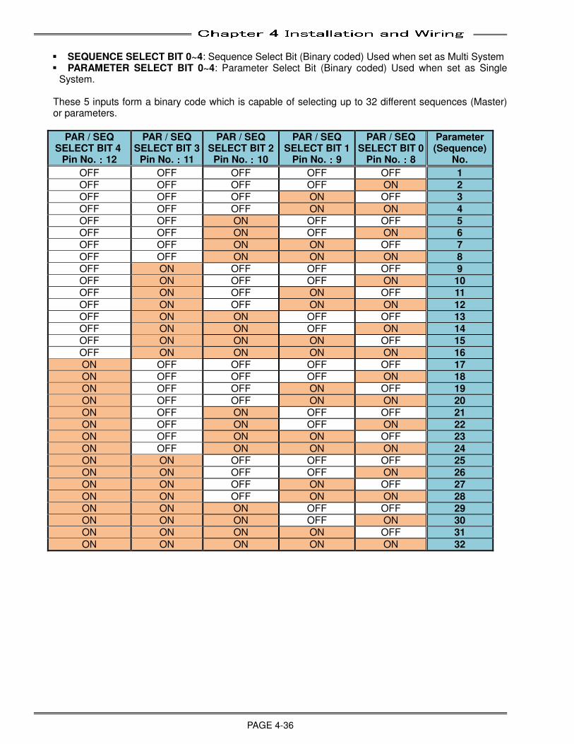
Chapter 4 Installation and Wiring
PAGE 4-36
SEQUENCE SELECT BIT 0~4: Sequence Select Bit (Binary coded) Used when set as Multi System PARAMETER SELECT BIT 0~4: Parameter Select Bit (Binary coded) Used when set as Single
System. These 5 inputs form a binary code which is capable of selecting up to 32 different sequences (Master) or parameters.
PAR / SEQ SELECT BIT 4
Pin No.::::12
PAR / SEQ SELECT BIT 3
Pin No.::::11
PAR / SEQ SELECT BIT 2 Pin No.::::10
PAR / SEQ SELECT BIT 1
Pin No.::::9
PAR / SEQ SELECT BIT 0
Pin No.::::8
Parameter (Sequence)
No.
OFF OFF OFF OFF OFF 1
OFF OFF OFF OFF ON 2
OFF OFF OFF ON OFF 3
OFF OFF OFF ON ON 4
OFF OFF ON OFF OFF 5
OFF OFF ON OFF ON 6
OFF OFF ON ON OFF 7
OFF OFF ON ON ON 8
OFF ON OFF OFF OFF 9
OFF ON OFF OFF ON 10
OFF ON OFF ON OFF 11
OFF ON OFF ON ON 12
OFF ON ON OFF OFF 13
OFF ON ON OFF ON 14
OFF ON ON ON OFF 15
OFF ON ON ON ON 16
ON OFF OFF OFF OFF 17
ON OFF OFF OFF ON 18
ON OFF OFF ON OFF 19
ON OFF OFF ON ON 20
ON OFF ON OFF OFF 21
ON OFF ON OFF ON 22
ON OFF ON ON OFF 23
ON OFF ON ON ON 24
ON ON OFF OFF OFF 25
ON ON OFF OFF ON 26
ON ON OFF ON OFF 27
ON ON OFF ON ON 28
ON ON ON OFF OFF 29
ON ON ON OFF ON 30
ON ON ON ON OFF 31
ON ON ON ON ON 32
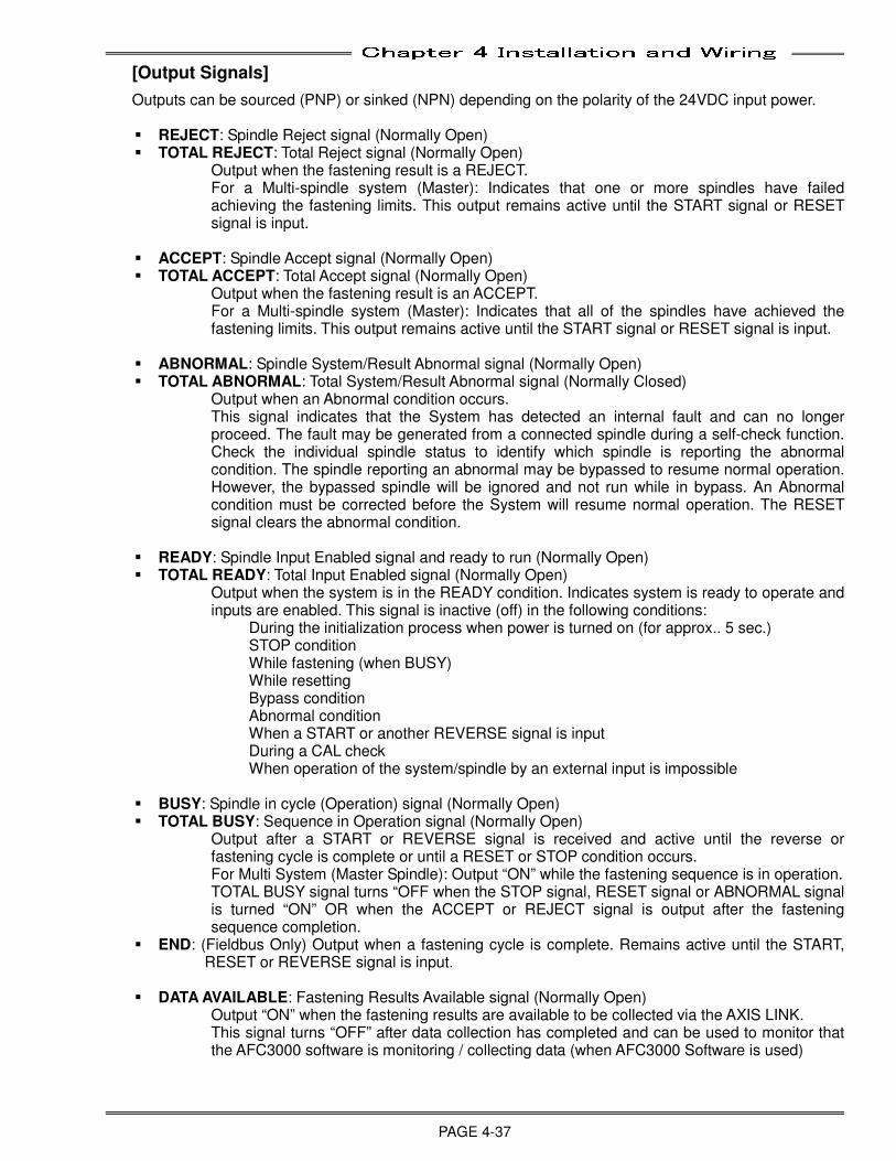
Chapter 4 Installation and Wiring
PAGE 4-37
[Output Signals]
Outputs can be sourced (PNP) or sinked (NPN) depending on the polarity of the 24VDC input power.
REJECT: Spindle Reject signal (Normally Open) TOTAL REJECT: Total Reject signal (Normally Open)
Output when the fastening result is a REJECT. For a Multi-spindle system (Master): Indicates that one or more spindles have failed achieving the fastening limits. This output remains active until the START signal or RESET signal is input.
ACCEPT: Spindle Accept signal (Normally Open) TOTAL ACCEPT: Total Accept signal (Normally Open)
Output when the fastening result is an ACCEPT. For a Multi-spindle system (Master): Indicates that all of the spindles have achieved the fastening limits. This output remains active until the START signal or RESET signal is input.
ABNORMAL: Spindle System/Result Abnormal signal (Normally Open) TOTAL ABNORMAL: Total System/Result Abnormal signal (Normally Closed)
Output when an Abnormal condition occurs. This signal indicates that the System has detected an internal fault and can no longer proceed. The fault may be generated from a connected spindle during a self-check function. Check the individual spindle status to identify which spindle is reporting the abnormal condition. The spindle reporting an abnormal may be bypassed to resume normal operation. However, the bypassed spindle will be ignored and not run while in bypass. An Abnormal condition must be corrected before the System will resume normal operation. The RESET signal clears the abnormal condition.
READY: Spindle Input Enabled signal and ready to run (Normally Open) TOTAL READY: Total Input Enabled signal (Normally Open)
Output when the system is in the READY condition. Indicates system is ready to operate and inputs are enabled. This signal is inactive (off) in the following conditions:
During the initialization process when power is turned on (for approx.. 5 sec.) STOP condition While fastening (when BUSY) While resetting Bypass condition Abnormal condition When a START or another REVERSE signal is input During a CAL check When operation of the system/spindle by an external input is impossible
BUSY: Spindle in cycle (Operation) signal (Normally Open) TOTAL BUSY: Sequence in Operation signal (Normally Open)
Output after a START or REVERSE signal is received and active until the reverse or fastening cycle is complete or until a RESET or STOP condition occurs. For Multi System (Master Spindle): Output “ON” while the fastening sequence is in operation. TOTAL BUSY signal turns “OFF when the STOP signal, RESET signal or ABNORMAL signal is turned “ON” OR when the ACCEPT or REJECT signal is output after the fastening sequence completion.
END: (Fieldbus Only) Output when a fastening cycle is complete. Remains active until the START, RESET or REVERSE signal is input.
DATA AVAILABLE: Fastening Results Available signal (Normally Open) Output “ON” when the fastening results are available to be collected via the AXIS LINK. This signal turns “OFF” after data collection has completed and can be used to monitor that the AFC3000 software is monitoring / collecting data (when AFC3000 Software is used)
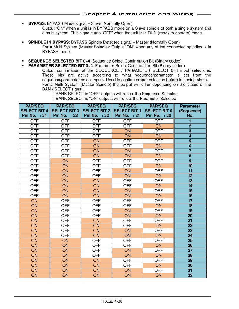
Chapter 4 Installation and Wiring
PAGE 4-38
BYPASS: BYPASS Mode signal – Slave (Normally Open)
Output “ON” when a unit is in BYPASS mode on a Slave spindle of both a single system and a multi system. This signal turns “OFF” when the unit is in RUN (ready to operate) mode.
SPINDLE IN BYPASS: BYPASS Spindle Detected signal – Master (Normally Open)
For a Multi System (Master Spindle): Output “ON” when any of the connected spindles is in BYPASS mode.
SEQUENCE SELECTED BIT 0~4: Sequence Select Confirmation Bit (Binary coded) PARAMETER SELECTED BIT 0~4: Parameter Select Confirmation Bit (Binary coded)
Output confirmation of the SEQUENCE / PARAMETER SELECT 0~4 input selections. These bits are active according to what sequence/parameter is set from the sequence/parameter select inputs. Used to confirm proper selection before fastening starts. For a Multi System (Master Spindle) the output will differ depending on the status of the BANK SELECT signal:
If BANK SELECT is “OFF” outputs will reflect the Sequence Selected If BANK SELECT is “ON” outputs will reflect the Parameter Selected
PAR/SEQ SELECT BIT 4 Pin No. ::::24
PAR/SEQ SELECT BIT 3 Pin No. ::::23
PAR/SEQ SELECT BIT 2 Pin No. ::::22
PAR/SEQ SELECT BIT 1 Pin No. ::::21
PAR/SEQ SELECT BIT 0 Pin No. ::::20
Parameter (Sequence)
No.
OFF OFF OFF OFF OFF 1
OFF OFF OFF OFF ON 2
OFF OFF OFF ON OFF 3
OFF OFF OFF ON ON 4
OFF OFF ON OFF OFF 5
OFF OFF ON OFF ON 6
OFF OFF ON ON OFF 7
OFF OFF ON ON ON 8
OFF ON OFF OFF OFF 9
OFF ON OFF OFF ON 10
OFF ON OFF ON OFF 11
OFF ON OFF ON ON 12
OFF ON ON OFF OFF 13
OFF ON ON OFF ON 14
OFF ON ON ON OFF 15
OFF ON ON ON ON 16
ON OFF OFF OFF OFF 17
ON OFF OFF OFF ON 18
ON OFF OFF ON OFF 19
ON OFF OFF ON ON 20
ON OFF ON OFF OFF 21
ON OFF ON OFF ON 22
ON OFF ON ON OFF 23
ON OFF ON ON ON 24
ON ON OFF OFF OFF 25
ON ON OFF OFF ON 26
ON ON OFF ON OFF 27
ON ON OFF ON ON 28
ON ON ON OFF OFF 29
ON ON ON OFF ON 30
ON ON ON ON OFF 31
ON ON ON ON ON 32
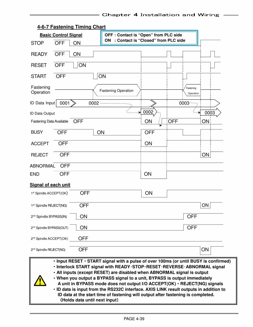
Chapter 4 Installation and Wiring
PAGE 4-39
4-6-7 Fastening Timing Chart
Basic Control Signal
STOP OFF ON
READY OFF ON
RESET OFF ON
START OFF ON
Fastening
Operation
Fastening Data Available OFF ON OFF ON
BUSY OFF ON OFF
ACCEPT OFF ON
REJECT OFF ON
ABNORMAL OFF
END OFF ON
Signal of each unit
1st Spindle ACCEPT(OK) OFF ON
1st Spindle REJECT(NG) OFF ON
2nd Spindle BYPASS(IN) ON OFF
2nd Spindle BYPASS(OUT) ON OFF
2nd Spindle ACCEPT(OK) OFF
2nd Spindle REJECT(NG) OFF ON ・・・・Input RESET・・・・START signal with a pulse of over 100ms (or until BUSY is confirmed) ・・・・Interlock START signal with READY・・・・STOP・・・・RESET・・・・REVERSE・・・・ABNORMAL signal ・・・・All inputs (except RESET) are disabled when ABNORMAL signal is output ・・・・When you output a BYPASS signal to a unit, BYPASS is output immediately
A unit in BYPASS mode does not output I/O ACCEPT(OK)・・・・REJECT(NG) signals ・・・・ID data is input from the RS232C interface. AXIS LINK result outputs in addition to
ID data at the start time of fastening will output after fastening is completed. ((((Holds data until next input))))
OFF::::Contact is “Open” from PLC side
ON ::::Contact is “Closed” from PLC side
0003
3
0002 0001
Fastening Operation Fastening Operation
ID Data Input
ID Data Output 0002 0003
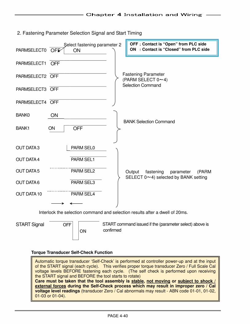
Chapter 4 Installation and Wiring
PAGE 4-40
2. Fastening Parameter Selection Signal and Start Timing
Select fastening parameter 2
OUT DATA 6 PARM SEL3
OUT DATA 10 PARM SEL4
Interlock the selection command and selection results after a dwell of 20ms.
START Signal OFF
ON
START command issued if the (parameter select) above is
confirmed
Torque Transducer Self-Check Function
PARMSELECT0 OFF ON
PARMSELECT1 OFF
PARMSELECT2 OFF
PARMSELECT3 OFF
PARMSELECT4 OFF
BANK0 ON
BANK Selection Command
BANK1 ON OFF
OUT DATA 3 PARM SEL0
OUT DATA 4 PARM SEL1
OUT DATA 5 PARM SEL2
Output fastening parameter (PARM
SELECT 0~4) selected by BANK setting
OFF::::Contact is “Open” from PLC side
ON ::::Contact is “Closed” from PLC side
Fastening Parameter
(PARM SELECT 0~4)
Selection Command
Automatic torque transducer ‘Self-Check’ is performed at controller power-up and at the input of the START signal (each cycle). This verifies proper torque transducer Zero / Full Scale Cal voltage levels BEFORE fastening each cycle. (The self check is performed upon receiving the START signal and BEFORE the tool starts to rotate) Care must be taken that the tool assembly is stable, not moving or subject to shock / external forces during the Self-Check process which may result in improper zero / Cal voltage level readings (transducer Zero / Cal abnormals may result - ABN code 01-01, 01-02, 01-03 or 01-04).
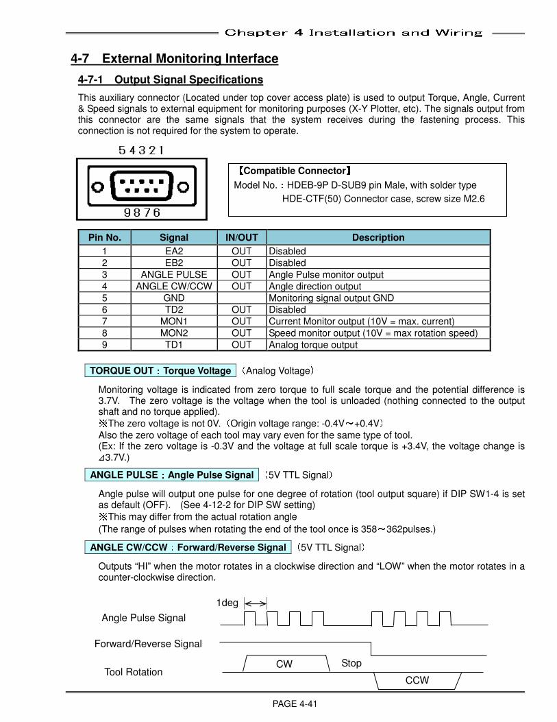
Chapter 4 Installation and Wiring
PAGE 4-41
4-7 External Monitoring Interface
4-7-1 Output Signal Specifications
This auxiliary connector (Located under top cover access plate) is used to output Torque, Angle, Current & Speed signals to external equipment for monitoring purposes (X-Y Plotter, etc). The signals output from this connector are the same signals that the system receives during the fastening process. This connection is not required for the system to operate.
Pin No. Signal IN/OUT Description
1 EA2 OUT Disabled
2 EB2 OUT Disabled
3 ANGLE PULSE OUT Angle Pulse monitor output
4 ANGLE CW/CCW OUT Angle direction output
5 GND Monitoring signal output GND
6 TD2 OUT Disabled
7 MON1 OUT Current Monitor output (10V = max. current)
8 MON2 OUT Speed monitor output (10V = max rotation speed)
9 TD1 OUT Analog torque output TORQUE OUT::::Torque Voltage (Analog Voltage)
Monitoring voltage is indicated from zero torque to full scale torque and the potential difference is 3.7V. The zero voltage is the voltage when the tool is unloaded (nothing connected to the output shaft and no torque applied). ※The zero voltage is not 0V.(Origin voltage range: -0.4V~+0.4V)
Also the zero voltage of each tool may vary even for the same type of tool. (Ex: If the zero voltage is -0.3V and the voltage at full scale torque is +3.4V, the voltage change is ⊿3.7V.)
ANGLE PULSE::::Angle Pulse Signal (5V TTL Signal)
Angle pulse will output one pulse for one degree of rotation (tool output square) if DIP SW1-4 is set as default (OFF). (See 4-12-2 for DIP SW setting) ※This may differ from the actual rotation angle
(The range of pulses when rotating the end of the tool once is 358~362pulses.)
ANGLE CW/CCW::::Forward/Reverse Signal (5V TTL Signal)
Outputs “HI” when the motor rotates in a clockwise direction and “LOW” when the motor rotates in a counter-clockwise direction.
【【【【Compatible Connector】】】】
Model No.:HDEB-9P D-SUB9 pin Male, with solder type
HDE-CTF(50) Connector case, screw size M2.6
Angle Pulse Signal
1deg
Forward/Reverse Signal
CCW Tool Rotation
CW Stop
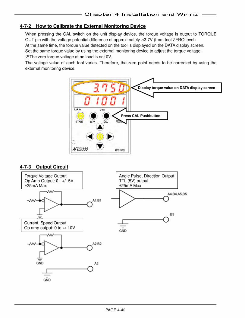
Chapter 4 Installation and Wiring
PAGE 4-42
4-7-2 How to Calibrate the External Monitoring Device
When pressing the CAL switch on the unit display device, the torque voltage is output to TORQUE
OUT pin with the voltage potential difference of approximately ⊿3.7V (from tool ZERO level)
At the same time, the torque value detected on the tool is displayed on the DATA display screen.
Set the same torque value by using the external monitoring device to adjust the torque voltage. ※The zero torque voltage at no load is not 0V.
The voltage value of each tool varies. Therefore, the zero point needs to be corrected by using the
external monitoring device.
4-7-3 Output Circuit
Display torque value on DATA display screen
Press CAL Pushbutton
Torque Voltage Output Op Amp Output: 0 - +/- 5V ±25mA Max
Current, Speed Output Op amp output: 0 to +/-10V
Angle Pulse, Direction Output TTL (5V) output ±25mA Max
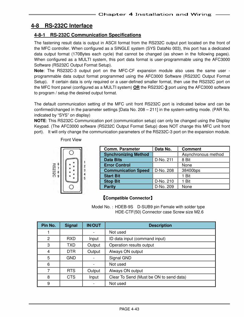
Chapter 4 Installation and Wiring
PAGE 4-43
4-8 RS-232C Interface
4-8-1 RS-232C Communication Specifications
The fastening result data is output in ASCII format from the RS232C output port located on the front of
the MFC controller. When configured as a SINGLE system (SYS DataNo 003), this port has a dedicated
data output format (170Bytes each cycle) that cannot be changed (as shown in the following pages).
When configured as a MULTI system, this port data format is user-programmable using the AFC3000
Software (RS232C Output Format Setup).
Note: The RS232C-3 output port on the MFC-CF expansion module also uses the same user -
programmable data output format programmed using the AFC3000 Software (RS232C Output Format
Setup). If certain data is only required or a user-defined smaller format, then use the RS232C port on
the MFC front panel (configured as a MULTI system) OR the RS232C-3 port using the AFC3000 software
to program / setup the desired output format.
The default communication setting of the MFC unit front RS232C port is indicated below and can be
confirmed/changed in the parameter settings [Data No. 208 – 211] in the system-setting mode. (PAR No.
indicated by “SYS” on display)
NOTE: This RS232C Communication port (communication setup) can only be changed using the Display
Keypad. (The AFC3000 software (RS232C Output Format Setup) does NOT change this MFC unit front
port). It will only change the communication parameters of the RS232C-3 port on the expansion module.
Comm. Parameter Data No. Comment
Synchronizing Method Asynchronous method
Data Bits D-No. 211 8 Bit
Error Control None
Communication Speed D-No. 208 38400bps
Start Bit 1 Bit
Stop Bit D-No. 210 1 Bit
Parity D-No. 209 None 【【【【Compatible Connector】】】】
Model No.:HDEB-9S D-SUB9 pin Female with solder type
HDE-CTF(50) Connector case Screw size M2.6
Pin No. Signal IN/OUT Description
1 - Not used
2 RXD Input ID data input (command input)
3 TXD Output Operation results output
4 DTR Output Always ON output
5 GND - Signal GND
6 - Not used
7 RTS Output Always ON output
8 CTS Input Clear To Send (Must be ON to send data)
9 - Not used
Front View
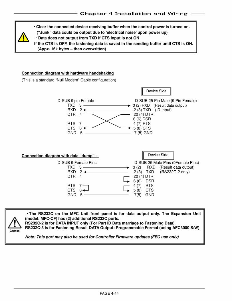
Chapter 4 Installation and Wiring
PAGE 4-44
・・・・Clear the connected device receiving buffer when the control power is turned on.
(“Junk” data could be output due to ‘electrical noise’ upon power up) ・・・・Data does not output from TXD if CTS input is not ON
If the CTS is OFF, the fastening data is saved in the sending buffer until CTS is ON.
(Appx. 16k bytes – then overwritten)
Connection diagram with hardware handshaking
(This is a standard “Null Modem” Cable configuration)
D-SUB 9 pin Female D-SUB 25 Pin Male (9 Pin Female) TXD 3 3 (2) RXD (Result data output)
RXD 2 2 (3) TXD (ID Input) DTR 4 20 (4) DTR
6 (6) DSR RTS 7 4 (7) RTS CTS 8 5 (8) CTS GND 5 7 (5) GND
Connection diagram with data “dump” -
D-SUB 9 Female Pins D-SUB 25 Male Pins (9Female Pins) TXD 3 3 (2) RXD (Result data output) RXD 2 2 (3) TXD (RS232C-2 only) DTR 4 20 (4) DTR
6 (6) DSR RTS 7 4 (7) RTS CTS 8 5 (8) CTS GND 5 7(5) GND
Device Side
Device Side
・・・・The RS232C on the MFC Unit front panel is for data output only. The Expansion Unit
(model: MFC-CF) has (2) additional RS232C ports. RS232C-2 is for DATA INPUT only (For Part ID Data marriage to Fastening Data) RS232C-3 is for Fastening Result DATA Output: Programmable Format (using AFC3000 S/W) Note: This port may also be used for Controller Firmware updates (FEC use only)
CautionCautionCautionCaution
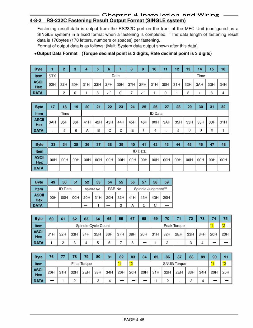
Chapter 4 Installation and Wiring
PAGE 4-45
4-8-2 RS-232C Fastening Result Output Format (SINGLE system)
Fastening result data is output from the RS232C port on the front of the MFC Unit (configured as a
SINGLE system) in a fixed format when a fastening is completed. The data length of fastening result
data is 170bytes (170 letters, numbers or spaces) per fastening.
Format of output data is as follows: (Multi System data output shown after this data) ●Output Data Format (Torque decimal point is 2 digits, Rate decimal point is 3 digits)
Byte 1 2 3 4 5 6 7 8 9 10 11 12 13 14 15 16
Item STX Date Time
ASCII
Hex 02H 32H 30H 31H 33H 2FH 30H 37H 2FH 31H 30H 31H 32H 3AH 33H 34H
DATA 2 0 1 3 / 0 7 / 1 0 1 2 : 3 4
Byte 17 18 19 20 21 22 23 24 25 26 27 28 29 30 31 32
Item Time ID Data
ASCII
Hex 3AH 35H 36H 41H 42H 43H 44H 45H 46H 00H 3AH 35H 33H 33H 33H 31H
DATA : 5 6 A B C D E F 4 : 5 3 3 3 1
Byte 33 34 35 36 37 38 39 40 41 42 43 44 45 46 47 48
Item ID Data
ASCII
Hex 00H 00H 00H 00H 00H 00H 00H 00H 00H 00H 00H 00H 00H 00H 00H 00H
DATA
Byte 49 50 51 52 53 54 55 56 57 58 59
Item ID Data Spindle No. PAR No. Spindle Judgment*3
ASCII
Hex 00H 00H 00H 20H 31H 20H 32H 41H 43H 43H 20H
DATA
] 1
] 2 A C C
]
Byte 60 61 62 63 64 65 66 67 68 69 70 71 72 73 74 75
Item Spindle Cycle Count Peak Torque *1 *2
ASCII
Hex 31H 32H 33H 34H 35H 36H 37H 38H 20H 31H 32H 2EH 33H 34H 20H 20H
DATA 1 2 3 4 5 6 7 8
] 1 2 . 3 4
] ]
Byte 76 77 78 79 80 81 82 83 84 85 86 87 88 89 90 91
Item Final Torque *1 *2 SNUG Torque *1 *2
ASCII
Hex 20H 31H 32H 2EH 33H 34H 20H 20H 20H 31H 32H 2EH 33H 34H 20H 20H
DATA
] 1 2 . 3 4
] ] ] 1 2 . 3 4
] ]
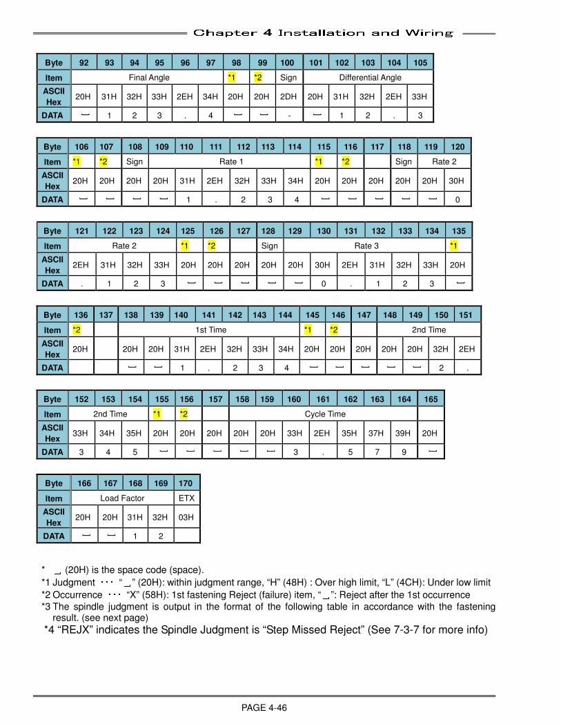
Chapter 4 Installation and Wiring
PAGE 4-46
Byte 92 93 94 95 96 97 98 99 100 101 102 103 104 105
Item Final Angle *1 *2 Sign Differential Angle
ASCII
Hex 20H 31H 32H 33H 2EH 34H 20H 20H 2DH 20H 31H 32H 2EH 33H
DATA
] 1 2 3 . 4
] ] -
] 1 2 . 3
Byte 106 107 108 109 110 111 112 113 114 115 116 117 118 119 120
Item *1 *2 Sign Rate 1 *1 *2 Sign Rate 2
ASCII
Hex 20H 20H 20H 20H 31H 2EH 32H 33H 34H 20H 20H 20H 20H 20H 30H
DATA
] ] ] ] 1 . 2 3 4
] ] ] ] ] 0
Byte 121 122 123 124 125 126 127 128 129 130 131 132 133 134 135
Item Rate 2 *1 *2 Sign Rate 3 *1
ASCII
Hex 2EH 31H 32H 33H 20H 20H 20H 20H 20H 30H 2EH 31H 32H 33H 20H
DATA . 1 2 3
] ] ] ] ] 0 . 1 2 3
]
Byte 136 137 138 139 140 141 142 143 144 145 146 147 148 149 150 151
Item *2 1st Time *1 *2 2nd Time
ASCII
Hex 20H 20H 20H 31H 2EH 32H 33H 34H 20H 20H 20H 20H 20H 32H 2EH
DATA
] ] 1 . 2 3 4
] ] ] ] ] 2 .
Byte 152 153 154 155 156 157 158 159 160 161 162 163 164 165
Item 2nd Time *1 *2 Cycle Time
ASCII
Hex 33H 34H 35H 20H 20H 20H 20H 20H 33H 2EH 35H 37H 39H 20H
DATA 3 4 5
] ] ] ] ] 3 . 5 7 9
]
Byte 166 167 168 169 170
Item Load Factor ETX
ASCII
Hex 20H 20H 31H 32H 03H
DATA
] ] 1 2
* ␣ (20H) is the space code (space).
*1 Judgment ・・・ “␣” (20H): within judgment range, “H” (48H) : Over high limit, “L” (4CH): Under low limit
*2 Occurrence ・・・ “X” (58H): 1st fastening Reject (failure) item, “␣”: Reject after the 1st occurrence
*3 The spindle judgment is output in the format of the following table in accordance with the fastening result. (see next page)
*4 “REJX” indicates the Spindle Judgment is “Step Missed Reject” (See 7-3-7 for more info)
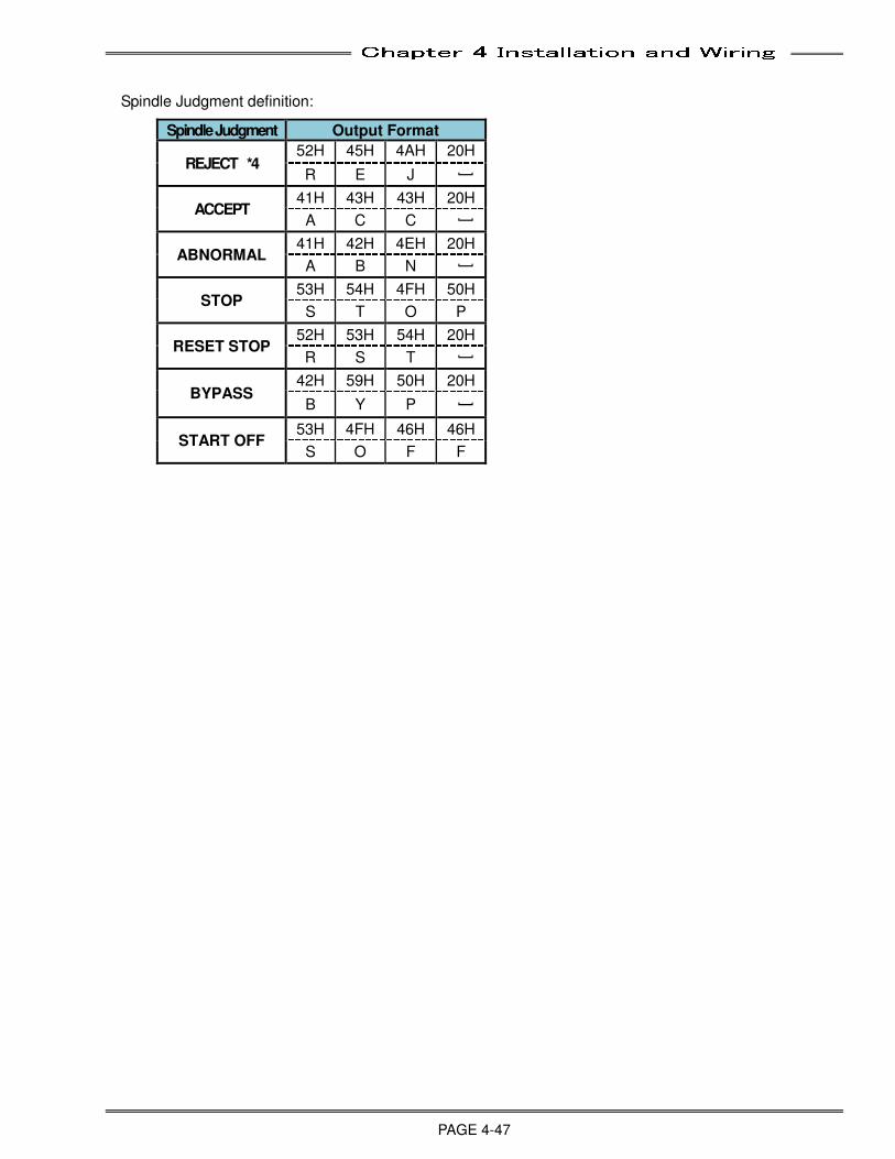
Chapter 4 Installation and Wiring
PAGE 4-47
Spindle Judgment definition:
Spindle Judgment Output Format
REJECT *4 52H 45H 4AH 20H
R E J [
ACCEPT 41H 43H 43H 20H
A C C [
ABNORMAL 41H 42H 4EH 20H
A B N [
STOP 53H 54H 4FH 50H
S T O P
RESET STOP 52H 53H 54H 20H
R S T [
BYPASS 42H 59H 50H 20H
B Y P [
START OFF 53H 4FH 46H 46H
S O F F
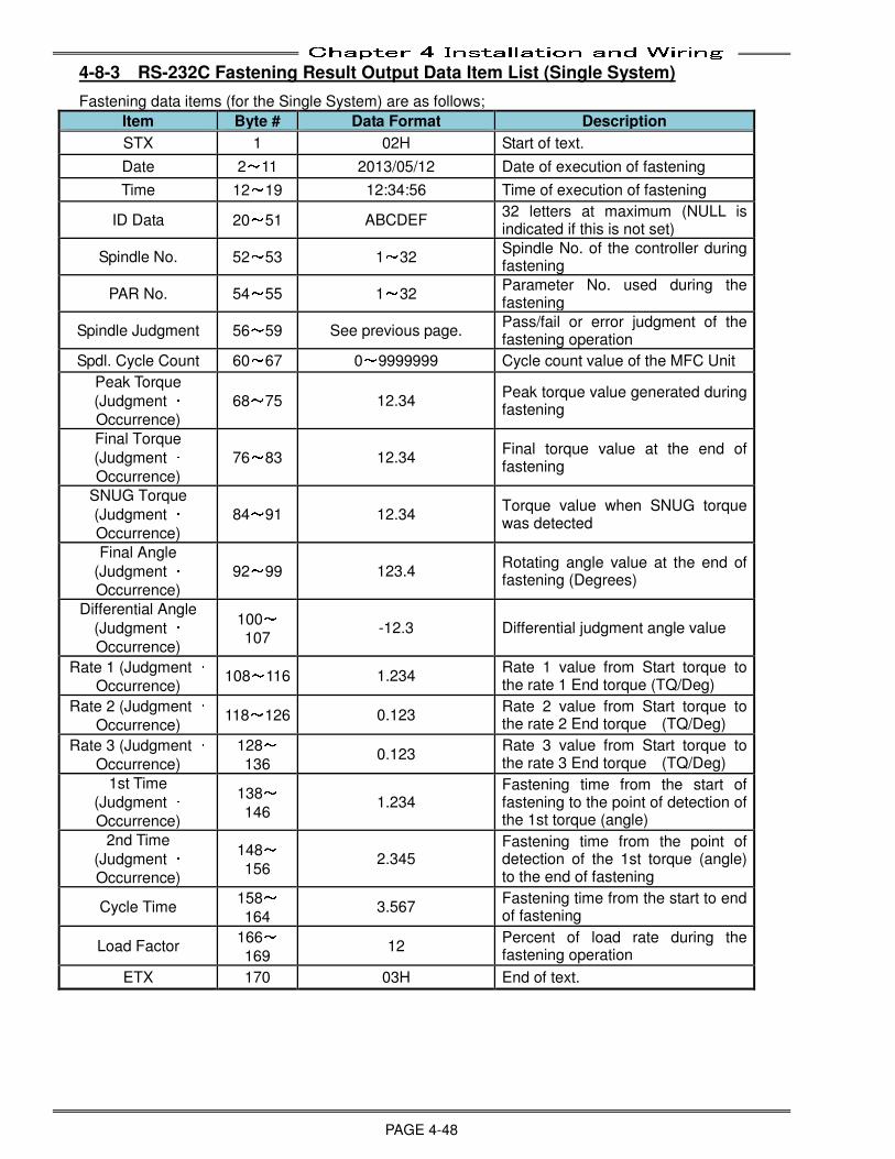
Chapter 4 Installation and Wiring
PAGE 4-48
4-8-3 RS-232C Fastening Result Output Data Item List (Single System)
Fastening data items (for the Single System) are as follows;
Item Byte # Data Format Description
STX 1 02H Start of text.
Date 2~11 2013/05/12 Date of execution of fastening
Time 12~19 12:34:56 Time of execution of fastening
ID Data 20~51 ABCDEF 32 letters at maximum (NULL is indicated if this is not set)
Spindle No. 52~53 1~32 Spindle No. of the controller during fastening
PAR No. 54~55 1~32 Parameter No. used during the fastening
Spindle Judgment 56~59 See previous page. Pass/fail or error judgment of the fastening operation
Spdl. Cycle Count 60~67 0~9999999 Cycle count value of the MFC Unit
Peak Torque
(Judgment ・ Occurrence)
68~75 12.34 Peak torque value generated during fastening
Final Torque
(Judgment ・ Occurrence)
76~83 12.34 Final torque value at the end of fastening
SNUG Torque
(Judgment ・ Occurrence)
84~91 12.34 Torque value when SNUG torque was detected
Final Angle
(Judgment ・ Occurrence)
92~99 123.4 Rotating angle value at the end of fastening (Degrees)
Differential Angle
(Judgment ・ Occurrence)
100~107
-12.3 Differential judgment angle value
Rate 1 (Judgment ・ Occurrence)
108~116 1.234 Rate 1 value from Start torque to the rate 1 End torque (TQ/Deg)
Rate 2 (Judgment ・ Occurrence)
118~126 0.123 Rate 2 value from Start torque to the rate 2 End torque (TQ/Deg)
Rate 3 (Judgment ・ Occurrence)
128~136
0.123 Rate 3 value from Start torque to the rate 3 End torque (TQ/Deg)
1st Time
(Judgment ・ Occurrence)
138~146
1.234 Fastening time from the start of fastening to the point of detection of the 1st torque (angle)
2nd Time
(Judgment ・ Occurrence)
148~156
2.345 Fastening time from the point of detection of the 1st torque (angle) to the end of fastening
Cycle Time 158~164
3.567 Fastening time from the start to end of fastening
Load Factor 166~169
12 Percent of load rate during the fastening operation
ETX 170 03H End of text.
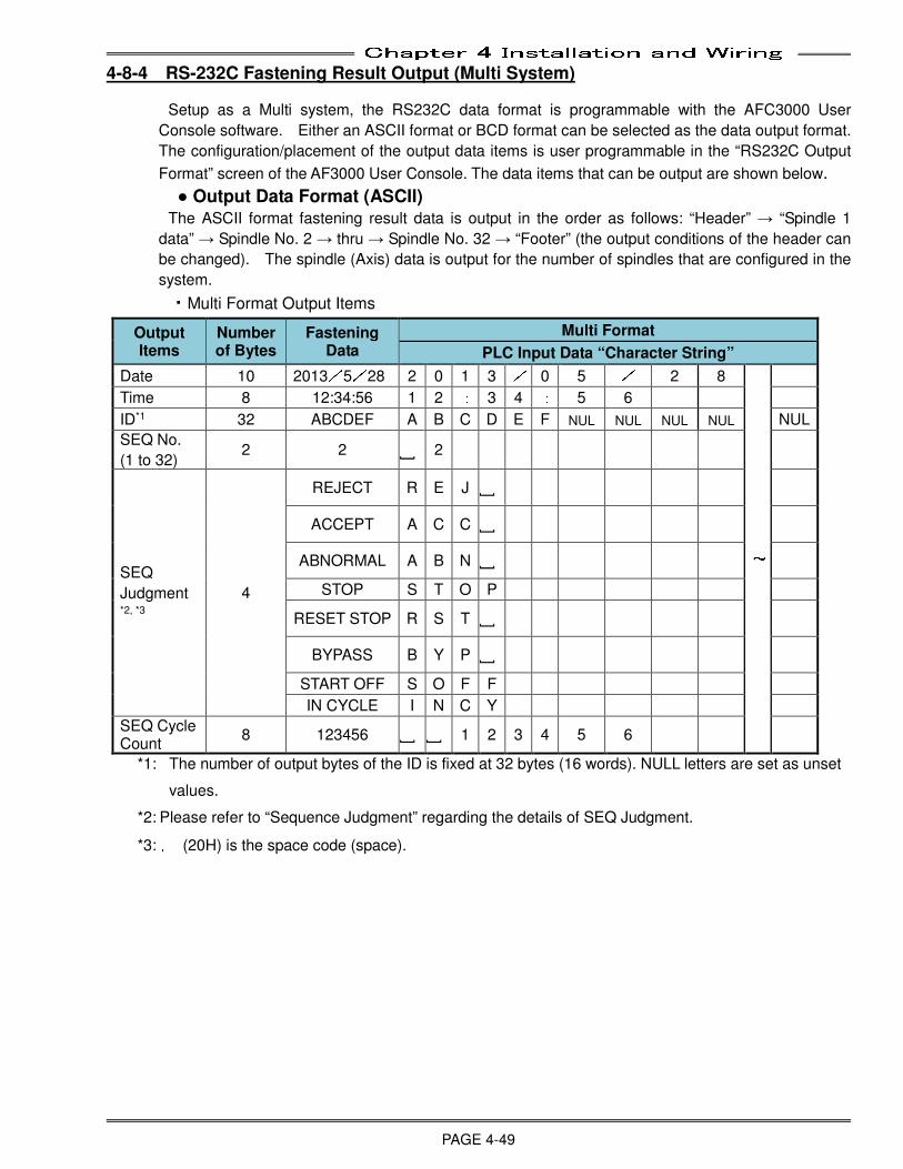
Chapter 4 Installation and Wiring
PAGE 4-49
4-8-4 RS-232C Fastening Result Output (Multi System)
Setup as a Multi system, the RS232C data format is programmable with the AFC3000 User
Console software. Either an ASCII format or BCD format can be selected as the data output format.
The configuration/placement of the output data items is user programmable in the “RS232C Output
Format” screen of the AF3000 User Console. The data items that can be output are shown below.
● Output Data Format (ASCII) The ASCII format fastening result data is output in the order as follows: “Header” → “Spindle 1
data” → Spindle No. 2 → thru → Spindle No. 32 → “Footer” (the output conditions of the header can
be changed). The spindle (Axis) data is output for the number of spindles that are configured in the
system.
・Multi Format Output Items
Output Items
Number of Bytes
Fastening Data
Multi Format
PLC Input Data “Character String”
Date 10 2013/5/28 2 0 1 3 / 0 5 / 2 8
~
Time 8 12:34:56 1 2 : 3 4 : 5 6
ID*1 32 ABCDEF A B C D E F NUL NUL NUL NUL NUL
SEQ No.
(1 to 32) 2 2 ] 2
SEQ
Judgment *2, *3
4
REJECT R E J ]
ACCEPT A C C ]
ABNORMAL A B N ]
STOP S T O P
RESET STOP R S T ]
BYPASS B Y P ]
START OFF S O F F
IN CYCLE I N C Y
SEQ Cycle Count
8 123456 ] ] 1 2 3 4 5 6
*1: The number of output bytes of the ID is fixed at 32 bytes (16 words). NULL letters are set as unset
values.
*2: Please refer to “Sequence Judgment” regarding the details of SEQ Judgment.
*3: ␣ (20H) is the space code (space).
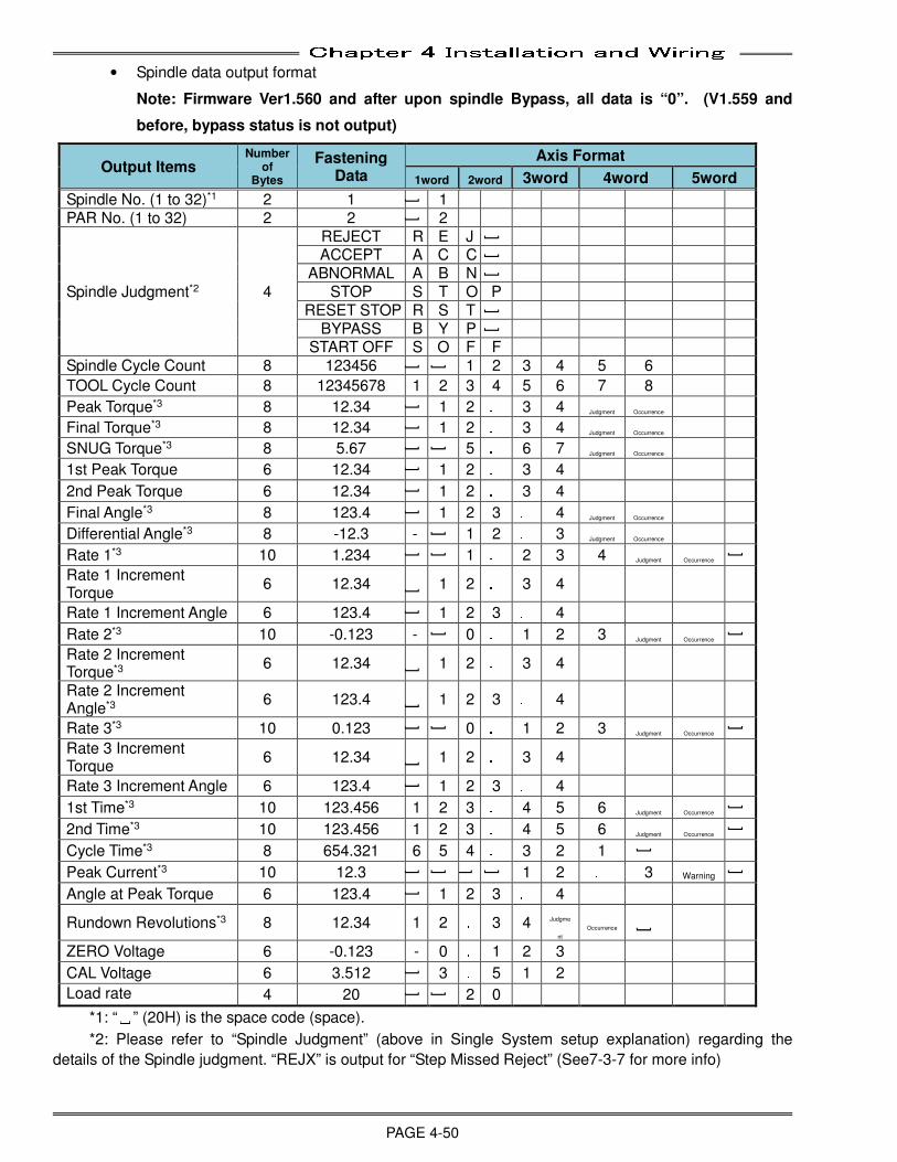
Chapter 4 Installation and Wiring
PAGE 4-50
• Spindle data output format
Note: Firmware Ver1.560 and after upon spindle Bypass, all data is “0”. (V1.559 and
before, bypass status is not output)
Output Items Number
of Bytes
Fastening Data
Axis Format
1word 2word 3word 4word 5word
Spindle No. (1 to 32)*1 2 1 ] 1 PAR No. (1 to 32) 2 2 ] 2
Spindle Judgment*2 4
REJECT R E J ] ACCEPT A C C ]
ABNORMAL A B N ] STOP S T O P
RESET STOP R S T ] BYPASS B Y P ]
START OFF S O F F Spindle Cycle Count 8 123456 ] ] 1 2 3 4 5 6
TOOL Cycle Count 8 12345678 1 2 3 4 5 6 7 8
Peak Torque*3 8 12.34 ] 1 2 . 3 4 Judgment Occurrence
Final Torque*3 8 12.34 ] 1 2 . 3 4 Judgment Occurrence
SNUG Torque*3 8 5.67 ] ] 5 . 6 7 Judgment Occurrence
1st Peak Torque 6 12.34 ] 1 2 . 3 4
2nd Peak Torque 6 12.34 ] 1 2 . 3 4
Final Angle*3 8 123.4
] 1 2 3 . 4 Judgment Occurrence
Differential Angle*3 8 -12.3 - ] 1 2 . 3 Judgment Occurrence
Rate 1*3 10 1.234
] ] 1 . 2 3 4 Judgment Occurrence
]
Rate 1 Increment Torque
6 12.34 ] 1 2 . 3 4
Rate 1 Increment Angle 6 123.4
] 1 2 3 . 4
Rate 2*3 10 -0.123 -
] 0 . 1 2 3 Judgment Occurrence
]
Rate 2 Increment Torque*3
6 12.34 ] 1 2 . 3 4
Rate 2 Increment Angle*3
6 123.4 ] 1 2 3 . 4
Rate 3*3 10 0.123
] ] 0 . 1 2 3 Judgment Occurrence
]
Rate 3 Increment Torque
6 12.34 ] 1 2 . 3 4
Rate 3 Increment Angle 6 123.4
] 1 2 3 . 4
1st Time*3 10 123.456 1 2 3 . 4 5 6 Judgment Occurrence
]
2nd Time*3 10 123.456 1 2 3 . 4 5 6 Judgment Occurrence
]
Cycle Time*3 8 654.321 6 5 4 . 3 2 1
]
Peak Current*3 10 12.3
] ] ] ] 1 2 . 3 Warning
]
Angle at Peak Torque 6 123.4
] 1 2 3 . 4
Rundown Revolutions*3 8 12.34 1 2 . 3 4 Judgme
nt Occurrence ]
ZERO Voltage 6 -0.123 - 0 . 1 2 3
CAL Voltage 6 3.512
] 3 . 5 1 2
Load rate 4 20
] ] 2 0
*1: “␣” (20H) is the space code (space).
*2: Please refer to “Spindle Judgment” (above in Single System setup explanation) regarding the
details of the Spindle judgment. “REJX” is output for “Step Missed Reject” (See7-3-7 for more info)
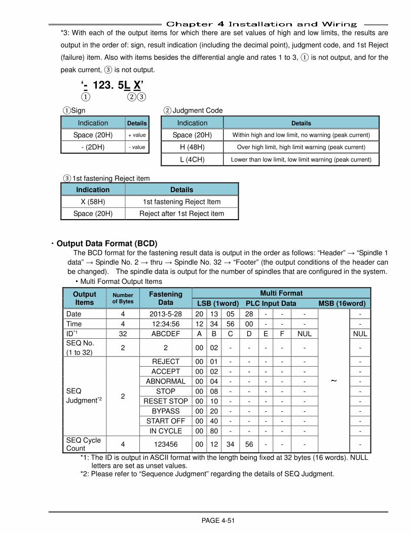
Chapter 4 Installation and Wiring
PAGE 4-51
*3: With each of the output items for which there are set values of high and low limits, the results are
output in the order of: sign, result indication (including the decimal point), judgment code, and 1st Reject
(failure) item. Also with items besides the differential angle and rates 1 to 3, ① is not output, and for the
peak current, ③ is not output.
‘- 123....5L X’
① ②③
①Sign ② Judgment Code
Indication Details Indication Details
Space (20H) + value Space (20H) Within high and low limit, no warning (peak current)
- (2DH) - value H (48H) Over high limit, high limit warning (peak current)
L (4CH) Lower than low limit, low limit warning (peak current)
③ 1st fastening Reject item
Indication Details
X (58H) 1st fastening Reject Item
Space (20H) Reject after 1st Reject item
・Output Data Format (BCD) The BCD format for the fastening result data is output in the order as follows: “Header” → “Spindle 1
data” → Spindle No. 2 → thru → Spindle No. 32 → “Footer” (the output conditions of the header can
be changed). The spindle data is output for the number of spindles that are configured in the system. ・Multi Format Output Items
Output Items
Number of Bytes
Fastening Data
Multi Format
LSB (1word) PLC Input Data MSB (16word)
Date 4 2013-5-28 20 13 05 28 - - -
~
-
Time 4 12:34:56 12 34 56 00 - - - -
ID*1 32 ABCDEF A B C D E F NUL NUL
SEQ No.
(1 to 32) 2 2 00 02 - - - - - -
SEQ
Judgment*2 2
REJECT 00 01 - - - - - -
ACCEPT 00 02 - - - - - -
ABNORMAL 00 04 - - - - - -
STOP 00 08 - - - - - -
RESET STOP 00 10 - - - - - -
BYPASS 00 20 - - - - - -
START OFF 00 40 - - - - - -
IN CYCLE 00 80 - - - - - -
SEQ Cycle Count
4 123456 00 12 34 56 - - - -
*1: The ID is output in ASCII format with the length being fixed at 32 bytes (16 words). NULL letters are set as unset values.
*2: Please refer to “Sequence Judgment” regarding the details of SEQ Judgment.
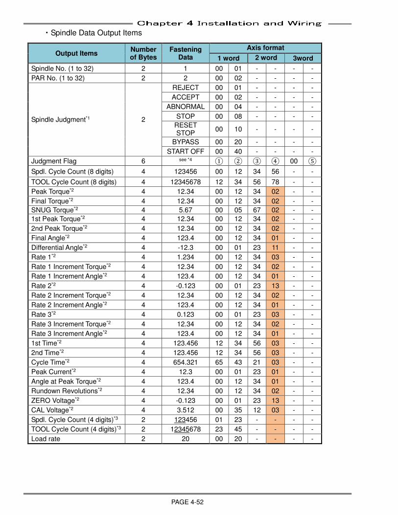
Chapter 4 Installation and Wiring
PAGE 4-52
・Spindle Data Output Items
Output Items Number of Bytes
Fastening Data
Axis format
1 word 2 word 3word
Spindle No. (1 to 32) 2 1 00 01 - - - -
PAR No. (1 to 32) 2 2 00 02 - - - -
Spindle Judgment*1 2
REJECT 00 01 - - - -
ACCEPT 00 02 - - - -
ABNORMAL 00 04 - - - -
STOP 00 08 - - - -
RESET STOP
00 10 - - - -
BYPASS 00 20 - - - -
START OFF 00 40 - - - -
Judgment Flag 6 see *4 ① ② ③ ④ 00 ⑤
Spdl. Cycle Count (8 digits) 4 123456 00 12 34 56 - -
TOOL Cycle Count (8 digits) 4 12345678 12 34 56 78 - -
Peak Torque*2 4 12.34 00 12 34 02 - -
Final Torque*2 4 12.34 00 12 34 02 - -
SNUG Torque*2 4 5.67 00 05 67 02 - -
1st Peak Torque*2 4 12.34 00 12 34 02 - -
2nd Peak Torque*2 4 12.34 00 12 34 02 - -
Final Angle*2 4 123.4 00 12 34 01 - -
Differential Angle*2 4 -12.3 00 01 23 11 - -
Rate 1*2 4 1.234 00 12 34 03 - -
Rate 1 Increment Torque*2 4 12.34 00 12 34 02 - -
Rate 1 Increment Angle*2 4 123.4 00 12 34 01 - -
Rate 2*2 4 -0.123 00 01 23 13 - -
Rate 2 Increment Torque*2 4 12.34 00 12 34 02 - -
Rate 2 Increment Angle*2 4 123.4 00 12 34 01 - -
Rate 3*2 4 0.123 00 01 23 03 - -
Rate 3 Increment Torque*2 4 12.34 00 12 34 02 - -
Rate 3 Increment Angle*2 4 123.4 00 12 34 01 - -
1st Time*2 4 123.456 12 34 56 03 - -
2nd Time*2 4 123.456 12 34 56 03 - -
Cycle Time*2 4 654.321 65 43 21 03 - -
Peak Current*2 4 12.3 00 01 23 01 - -
Angle at Peak Torque*2 4 123.4 00 12 34 01 - -
Rundown Revolutions*2 4 12.34 00 12 34 02 - -
ZERO Voltage*2 4 -0.123 00 01 23 13 - -
CAL Voltage*2 4 3.512 00 35 12 03 - -
Spdl. Cycle Count (4 digits)*3 2 123456 01 23 - - - -
TOOL Cycle Count (4 digits)*3 2 12345678 23 45 - - - -
Load rate 2 20 00 20 - - - -
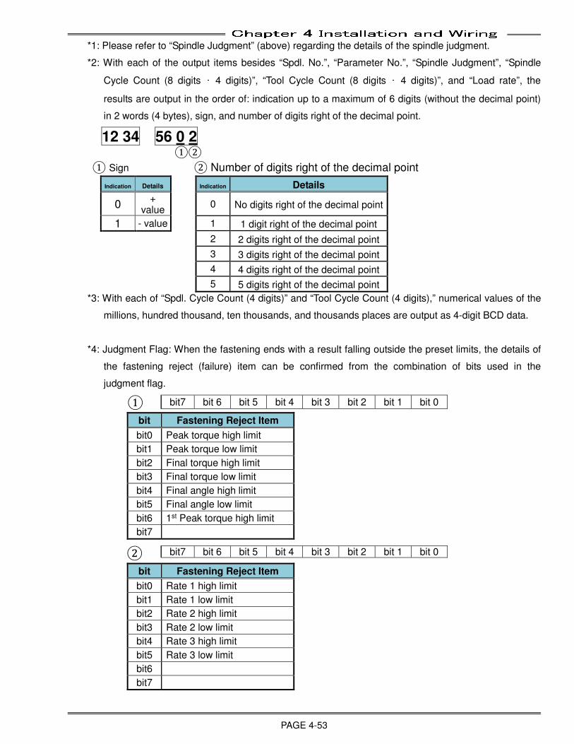
Chapter 4 Installation and Wiring
PAGE 4-53
*1: Please refer to “Spindle Judgment” (above) regarding the details of the spindle judgment.
*2: With each of the output items besides “Spdl. No.”, “Parameter No.”, “Spindle Judgment”, “Spindle
Cycle Count (8 digits ・ 4 digits)”, “Tool Cycle Count (8 digits ・ 4 digits)”, and “Load rate”, the
results are output in the order of: indication up to a maximum of 6 digits (without the decimal point)
in 2 words (4 bytes), sign, and number of digits right of the decimal point.
12 34 56 0 2 ①②
① Sign ② Number of digits right of the decimal point
Indication Details Indication Details
0 +
value 0 No digits right of the decimal point
1 - value 1 1 digit right of the decimal point
2 2 digits right of the decimal point
3 3 digits right of the decimal point
4 4 digits right of the decimal point
5 5 digits right of the decimal point
*3: With each of “Spdl. Cycle Count (4 digits)” and “Tool Cycle Count (4 digits),” numerical values of the
millions, hundred thousand, ten thousands, and thousands places are output as 4-digit BCD data.
*4: Judgment Flag: When the fastening ends with a result falling outside the preset limits, the details of
the fastening reject (failure) item can be confirmed from the combination of bits used in the
judgment flag.
①
bit Fastening Reject Item
bit0 Peak torque high limit
bit1 Peak torque low limit
bit2 Final torque high limit
bit3 Final torque low limit
bit4 Final angle high limit
bit5 Final angle low limit
bit6 1st Peak torque high limit
bit7
②
bit Fastening Reject Item
bit0 Rate 1 high limit
bit1 Rate 1 low limit
bit2 Rate 2 high limit
bit3 Rate 2 low limit
bit4 Rate 3 high limit
bit5 Rate 3 low limit
bit6
bit7
bit7 bit 6 bit 5 bit 4 bit 3 bit 2 bit 1 bit 0
bit7 bit 6 bit 5 bit 4 bit 3 bit 2 bit 1 bit 0
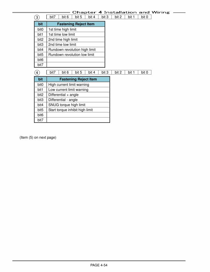
Chapter 4 Installation and Wiring
PAGE 4-54
③
bit Fastening Reject Item
bit0 1st time high limit
bit1 1st time low limit
bit2 2nd time high limit
bit3 2nd time low limit
bit4 Rundown revolution high limit
bit5 Rundown revolution low limit
bit6
bit7
④
bit Fastening Reject Item
bit0 High current limit warning
bit1 Low current limit warning
bit2 Differential + angle
bit3 Differential - angle
bit4 SNUG torque high limit
bit5 Start torque inhibit high limit
bit6
bit7
(Item (5) on next page)
bit7 bit 6 bit 5 bit 4 bit 3 bit 2 bit 1 bit 0
bit7 bit 6 bit 5 bit 4 bit 3 bit 2 bit 1 bit 0
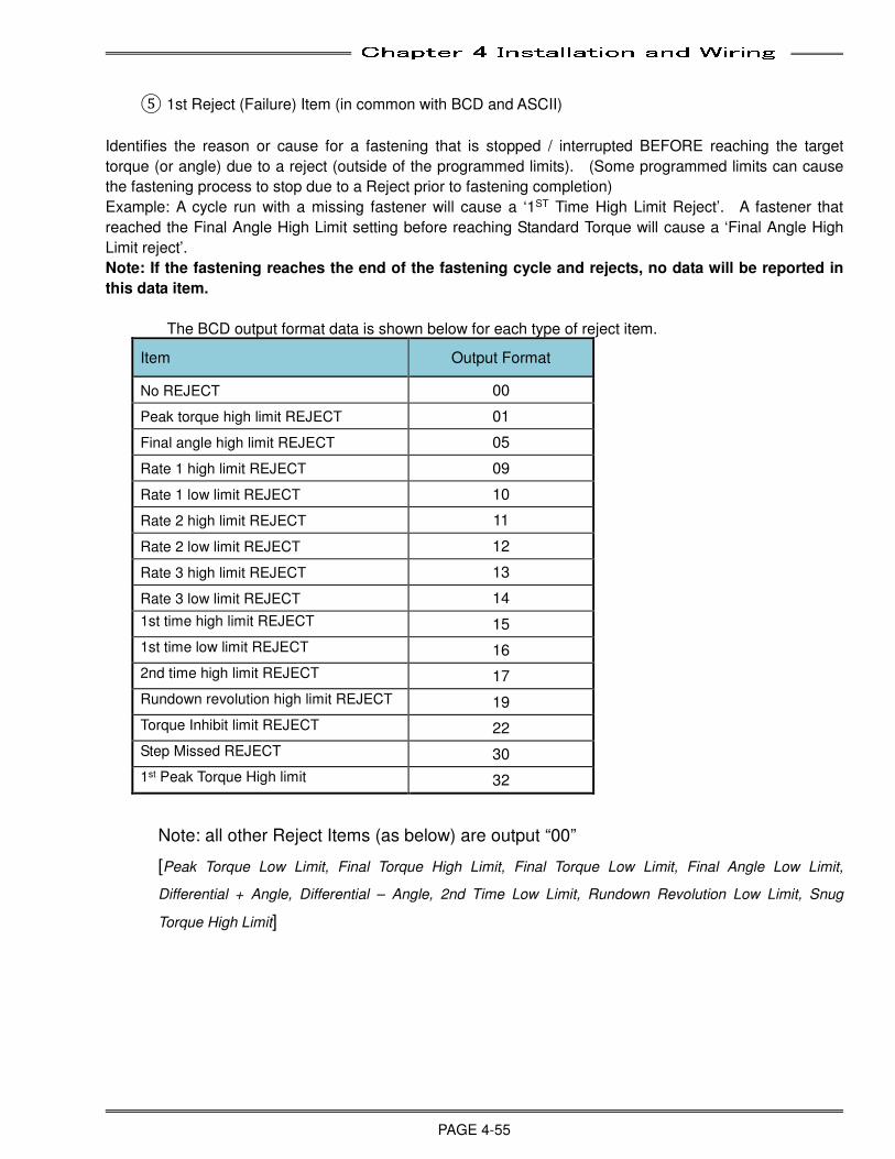
Chapter 4 Installation and Wiring
PAGE 4-55
⑤ 1st Reject (Failure) Item (in common with BCD and ASCII)
Identifies the reason or cause for a fastening that is stopped / interrupted BEFORE reaching the target
torque (or angle) due to a reject (outside of the programmed limits). (Some programmed limits can cause
the fastening process to stop due to a Reject prior to fastening completion)
Example: A cycle run with a missing fastener will cause a ‘1ST Time High Limit Reject’. A fastener that
reached the Final Angle High Limit setting before reaching Standard Torque will cause a ‘Final Angle High
Limit reject’.
Note: If the fastening reaches the end of the fastening cycle and rejects, no data will be reported in
this data item.
The BCD output format data is shown below for each type of reject item.
Item Output Format
No REJECT 00
Peak torque high limit REJECT 01
Final angle high limit REJECT 05
Rate 1 high limit REJECT 09
Rate 1 low limit REJECT 10
Rate 2 high limit REJECT 11
Rate 2 low limit REJECT 12
Rate 3 high limit REJECT 13
Rate 3 low limit REJECT 14
1st time high limit REJECT 15
1st time low limit REJECT 16
2nd time high limit REJECT 17
Rundown revolution high limit REJECT 19
Torque Inhibit limit REJECT 22
Step Missed REJECT 30
1st Peak Torque High limit 32
Note: all other Reject Items (as below) are output “00”
[Peak Torque Low Limit, Final Torque High Limit, Final Torque Low Limit, Final Angle Low Limit,
Differential + Angle, Differential – Angle, 2nd Time Low Limit, Rundown Revolution Low Limit, Snug
Torque High Limit]

Chapter 4 Installation and Wiring
PAGE 4-56
● Judgment Flag Output Examples
Example 1: Final torque low limit reject, final angle low limit reject, 2nd time high limit reject (1st reject
item)
①
②
③
④
Example 2: Peak torque low limit reject, rate 2 high limit reject (1st reject Item), 1st time low limit NG
①
②
③
④
Example 3: Final angle high limit reject (1st reject Item), Differential - angle reject, low current limit
warning
①
②
③
④
bit7 bit 6 bit 5 bit 4 bit 3 bit 2 bit 1 bit 0
0 0 1 0 1 0 0 0
0 0 0 0 0 0 0 0
0 0 0 0 0 1 0 0
0 0 0 0 0 0 0 0
Output Item Spdl. Format
1 word 2 word 3 word
Judgment Flag
① ② ③ ④ - ⑤
28 00 04 00 00 17
bit7 bit 6 bit 5 bit 4 bit 3 bit 2 bit 1 bit 0
0 0 0 0 0 0 1 0
0 0 0 0 0 1 0 0
0 0 0 0 0 0 1 0
0 0 0 0 0 0 0 0
Output Item Spdl. Format
1 word 1 word
Judgment Flag
① ② ③ ④ - ⑤
02 04 02 00 00 11
bit7 bit 6 bit 5 bit 4 bit 3 bit 2 bit 1 bit 0
0 0 0 1 0 0 0 0
0 0 0 0 0 0 0 0
0 0 0 0 0 0 0 0
0 0 0 0 1 0 1 0
Output Item Spdl. Format
1 word 2 word 3 word
Judgment Flag
① ② ③ ④ - ⑤
10 00 00 0A 00 05
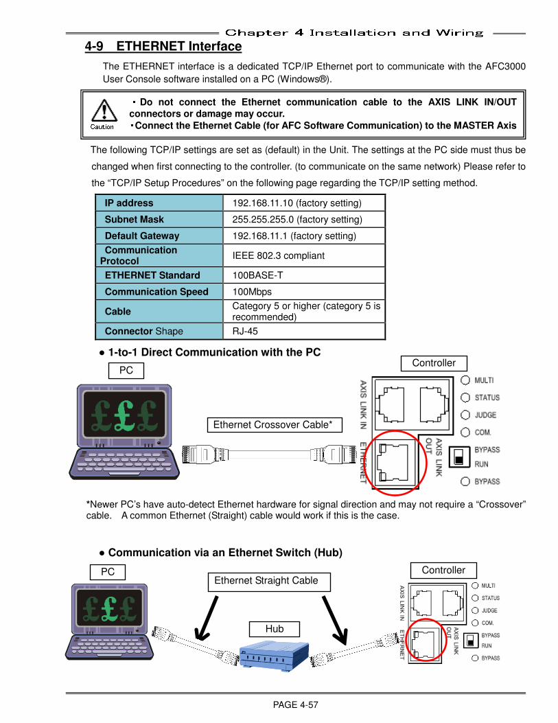
Chapter 4 Installation and Wiring
PAGE 4-57
4-9 ETHERNET Interface
The ETHERNET interface is a dedicated TCP/IP Ethernet port to communicate with the AFC3000
User Console software installed on a PC (Windows®).
The following TCP/IP settings are set as (default) in the Unit. The settings at the PC side must thus be
changed when first connecting to the controller. (to communicate on the same network) Please refer to
the “TCP/IP Setup Procedures” on the following page regarding the TCP/IP setting method.
IP address 192.168.11.10 (factory setting)
Subnet Mask 255.255.255.0 (factory setting)
Default Gateway 192.168.11.1 (factory setting)
Communication Protocol
IEEE 802.3 compliant
ETHERNET Standard 100BASE-T
Communication Speed 100Mbps
Cable Category 5 or higher (category 5 is recommended)
Connector Shape RJ-45
● 1-to-1 Direct Communication with the PC
*Newer PC’s have auto-detect Ethernet hardware for signal direction and may not require a “Crossover” cable. A common Ethernet (Straight) cable would work if this is the case.
● Communication via an Ethernet Switch (Hub)
・・・・Do not connect the Ethernet communication cable to the AXIS LINK IN/OUT
connectors or damage may occur. ・・・・Connect the Ethernet Cable (for AFC Software Communication) to the MASTER Axis Caution
Ethernet Crossover Cable*
Ethernet Straight Cable PC
PC Controller
Controller
Hub
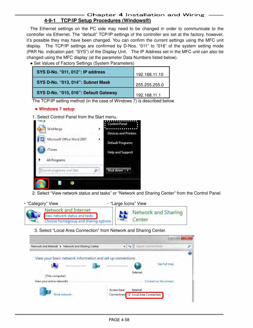
Chapter 4 Installation and Wiring
PAGE 4-58
4-9-1 TCP/IP Setup Procedures (Windows®)
The Ethernet settings on the PC side may need to be changed in order to communicate to the
controller via Ethernet. The “default” TCP/IP settings of the controller are set at the factory, however,
it’s possible they may have been changed. You can confirm the current settings using the MFC unit
display. The TCP/IP settings are confirmed by D-Nos. “011” to “016” of the system setting mode
(PAR No. indication part: “SYS”) of the Display Unit. The IP Address set in the MFC unit can also be
changed using the MFC display (at the parameter Data Numbers listed below).
● Set Values of Factory Settings (System Parameters)
SYS D-No. “011, 012”: IP address 192.168.11.10
SYS D-No. “013, 014”: Subnet Mask 255.255.255.0
SYS D-No. “015, 016”: Default Gateway 192.168.11.1
The TCP/IP setting method (in the case of Windows 7) is described below.
● Windows 7 setup
1. Select Control Panel from the Start menu.
2. Select “View network status and tasks” or “Network and Sharing Center” from the Control Panel. ・“Category” View ・“Large Icons” View
3. Select “Local Area Connection” from Network and Sharing Center.
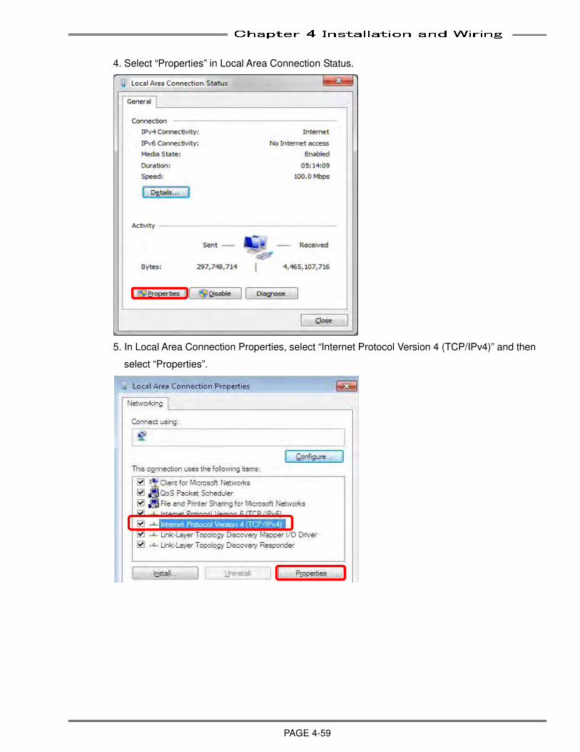
Chapter 4 Installation and Wiring
PAGE 4-59
4. Select “Properties” in Local Area Connection Status.
5. In Local Area Connection Properties, select “Internet Protocol Version 4 (TCP/IPv4)” and then
select “Properties”.
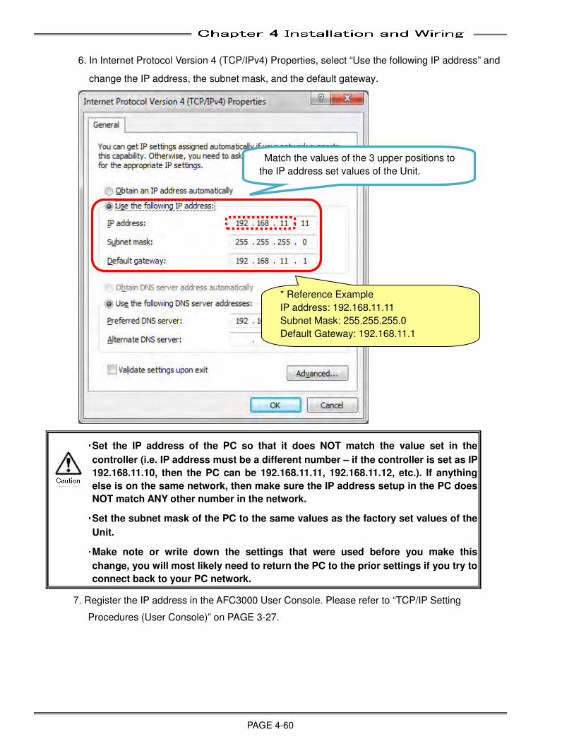
Chapter 4 Installation and Wiring
PAGE 4-60
6. In Internet Protocol Version 4 (TCP/IPv4) Properties, select “Use the following IP address” and
change the IP address, the subnet mask, and the default gateway.
・・・・ Set the IP address of the PC so that it does NOT match the value set in the
controller (i.e. IP address must be a different number – if the controller is set as IP
192.168.11.10, then the PC can be 192.168.11.11, 192.168.11.12, etc.). If anything
else is on the same network, then make sure the IP address setup in the PC does
NOT match ANY other number in the network. ・・・・ Set the subnet mask of the PC to the same values as the factory set values of the
Unit. ・・・・ Make note or write down the settings that were used before you make this
change, you will most likely need to return the PC to the prior settings if you try to
connect back to your PC network.
7. Register the IP address in the AFC3000 User Console. Please refer to “TCP/IP Setting
Procedures (User Console)” on PAGE 3-27.
* Reference Example
IP address: 192.168.11.11
Subnet Mask: 255.255.255.0
Default Gateway: 192.168.11.1
Match the values of the 3 upper positions to
the IP address set values of the Unit.
Caution
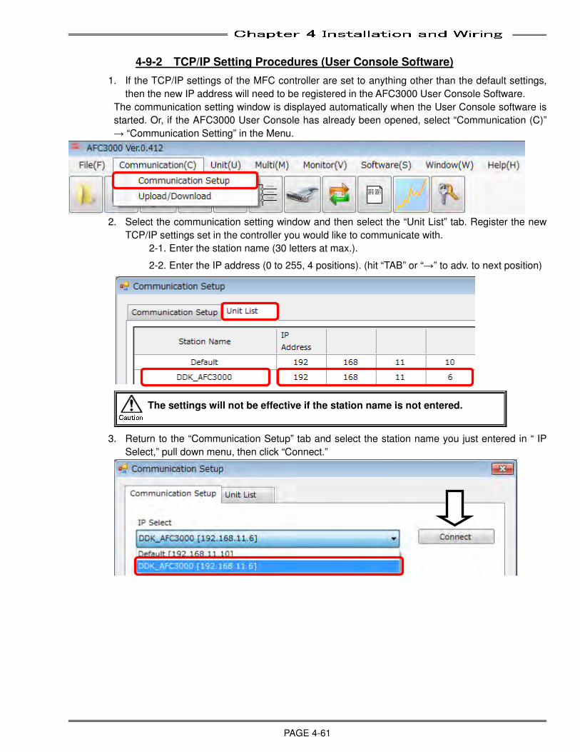
Chapter 4 Installation and Wiring
PAGE 4-61
4-9-2 TCP/IP Setting Procedures (User Console Software)
1. If the TCP/IP settings of the MFC controller are set to anything other than the default settings,
then the new IP address will need to be registered in the AFC3000 User Console Software.
The communication setting window is displayed automatically when the User Console software is
started. Or, if the AFC3000 User Console has already been opened, select “Communication (C)”
→ “Communication Setting” in the Menu.
2. Select the communication setting window and then select the “Unit List” tab. Register the new
TCP/IP settings set in the controller you would like to communicate with.
2-1. Enter the station name (30 letters at max.).
2-2. Enter the IP address (0 to 255, 4 positions). (hit “TAB” or “→” to adv. to next position)
The settings will not be effective if the station name is not entered.
3. Return to the “Communication Setup” tab and select the station name you just entered in “ IP
Select,” pull down menu, then click “Connect.”
Caution
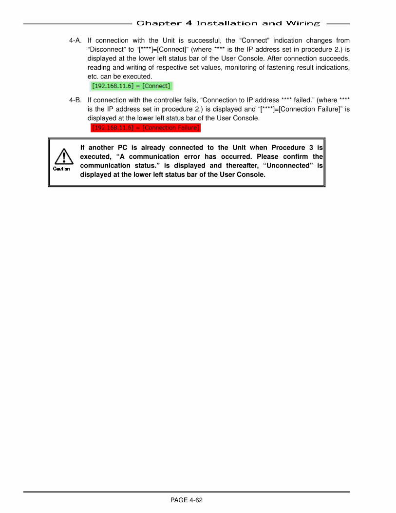
Chapter 4 Installation and Wiring
PAGE 4-62
4-A. If connection with the Unit is successful, the “Connect” indication changes from
“Disconnect” to “[****]=[Connect]” (where **** is the IP address set in procedure 2.) is
displayed at the lower left status bar of the User Console. After connection succeeds,
reading and writing of respective set values, monitoring of fastening result indications,
etc. can be executed.
4-B. If connection with the controller fails, “Connection to IP address **** failed.” (where ****
is the IP address set in procedure 2.) is displayed and “[****]=[Connection Failure]” is
displayed at the lower left status bar of the User Console.
If another PC is already connected to the Unit when Procedure 3 is
executed, “A communication error has occurred. Please confirm the
communication status.” is displayed and thereafter, “Unconnected” is
displayed at the lower left status bar of the User Console. CautionCautionCautionCaution
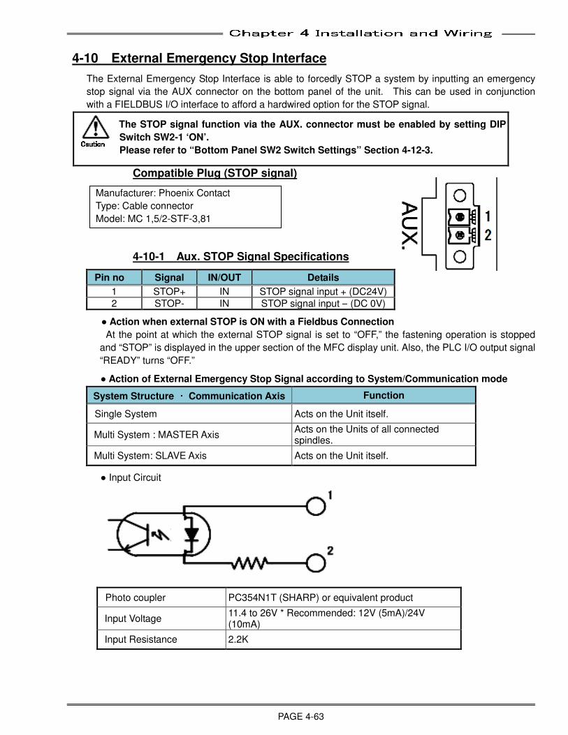
Chapter 4 Installation and Wiring
PAGE 4-63
4-10 External Emergency Stop Interface
The External Emergency Stop Interface is able to forcedly STOP a system by inputting an emergency
stop signal via the AUX connector on the bottom panel of the unit. This can be used in conjunction
with a FIELDBUS I/O interface to afford a hardwired option for the STOP signal.
The STOP signal function via the AUX. connector must be enabled by setting DIP
Switch SW2-1 ‘ON’.
Please refer to “Bottom Panel SW2 Switch Settings” Section 4-12-3.
Compatible Plug (STOP signal)
4-10-1 Aux. STOP Signal Specifications
Pin no Signal IN/OUT Details
1 STOP+ IN STOP signal input + (DC24V)
2 STOP- IN STOP signal input – (DC 0V)
● Action when external STOP is ON with a Fieldbus Connection
At the point at which the external STOP signal is set to “OFF,” the fastening operation is stopped
and “STOP” is displayed in the upper section of the MFC display unit. Also, the PLC I/O output signal
“READY” turns “OFF.”
● Action of External Emergency Stop Signal according to System/Communication mode
System Structure ・・・・ Communication Axis Function
Single System Acts on the Unit itself.
Multi System : MASTER Axis Acts on the Units of all connected spindles.
Multi System: SLAVE Axis Acts on the Unit itself.
● Input Circuit
Photo coupler PC354N1T (SHARP) or equivalent product
Input Voltage 11.4 to 26V * Recommended: 12V (5mA)/24V (10mA)
Input Resistance 2.2K
Manufacturer: Phoenix Contact
Type: Cable connector
Model: MC 1,5/2-STF-3,81
CautionCautionCautionCaution
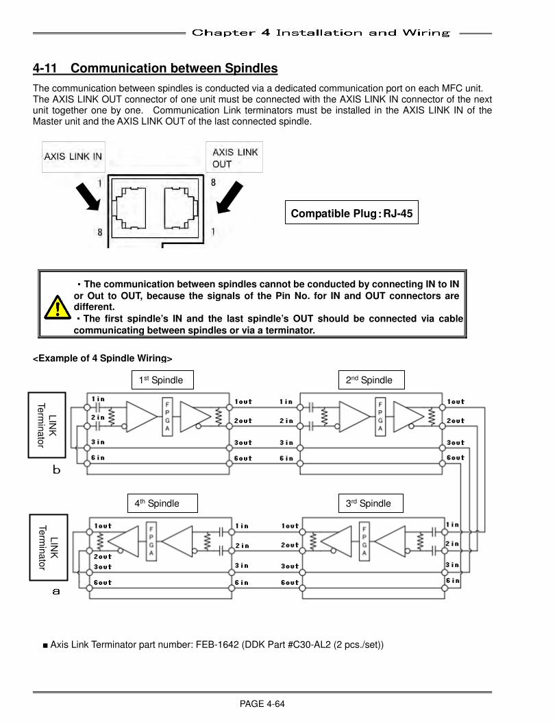
Chapter 4 Installation and Wiring
PAGE 4-64
4-11 Communication between Spindles
The communication between spindles is conducted via a dedicated communication port on each MFC unit. The AXIS LINK OUT connector of one unit must be connected with the AXIS LINK IN connector of the next unit together one by one. Communication Link terminators must be installed in the AXIS LINK IN of the Master unit and the AXIS LINK OUT of the last connected spindle.
・・・・The communication between spindles cannot be conducted by connecting IN to IN
or Out to OUT, because the signals of the Pin No. for IN and OUT connectors are different. ・・・・The first spindle’s IN and the last spindle’s OUT should be connected via cable
communicating between spindles or via a terminator.
<Example of 4 Spindle Wiring> ■ Axis Link Terminator part number: FEB-1642 (DDK Part #C30-AL2 (2 pcs./set))
Compatible Plug::::RJ-45
2nd Spindle
4th Spindle 3rd Spindle L
INK
Te
rmin
ato
r
LIN
K
Te
rmin
ato
r
1st Spindle
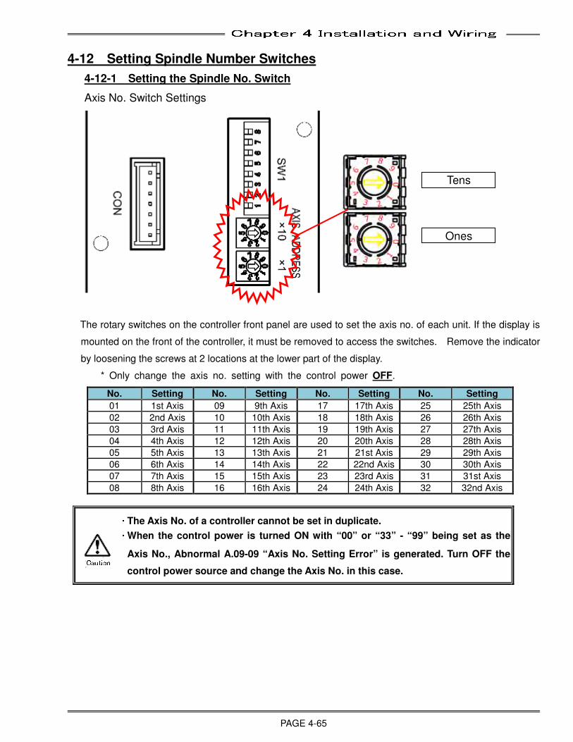
Chapter 4 Installation and Wiring
PAGE 4-65
4-12 Setting Spindle Number Switches
4-12-1 Setting the Spindle No. Switch
Axis No. Switch Settings
The rotary switches on the controller front panel are used to set the axis no. of each unit. If the display is
mounted on the front of the controller, it must be removed to access the switches. Remove the indicator
by loosening the screws at 2 locations at the lower part of the display.
* Only change the axis no. setting with the control power OFF.
No. Setting No. Setting No. Setting No. Setting
01 1st Axis 09 9th Axis 17 17th Axis 25 25th Axis
02 2nd Axis 10 10th Axis 18 18th Axis 26 26th Axis
03 3rd Axis 11 11th Axis 19 19th Axis 27 27th Axis
04 4th Axis 12 12th Axis 20 20th Axis 28 28th Axis
05 5th Axis 13 13th Axis 21 21st Axis 29 29th Axis
06 6th Axis 14 14th Axis 22 22nd Axis 30 30th Axis
07 7th Axis 15 15th Axis 23 23rd Axis 31 31st Axis
08 8th Axis 16 16th Axis 24 24th Axis 32 32nd Axis
・・・・ The Axis No. of a controller cannot be set in duplicate. ・・・・ When the control power is turned ON with “00” or “33” - “99” being set as the
Axis No., Abnormal A.09-09 “Axis No. Setting Error” is generated. Turn OFF the
control power source and change the Axis No. in this case.
Tens
Ones
Caution
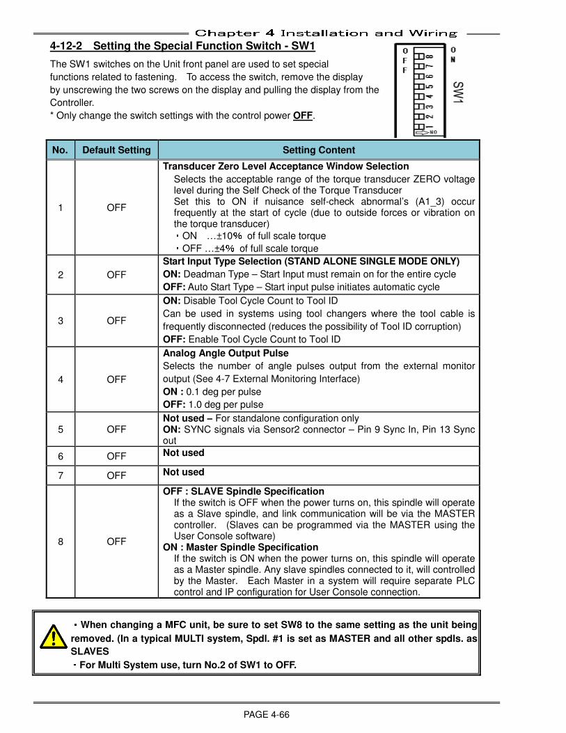
Chapter 4 Installation and Wiring
PAGE 4-66
4-12-2 Setting the Special Function Switch - SW1
The SW1 switches on the Unit front panel are used to set special
functions related to fastening. To access the switch, remove the display
by unscrewing the two screws on the display and pulling the display from the
Controller.
* Only change the switch settings with the control power OFF.
No. Default Setting Setting Content
1 OFF
Transducer Zero Level Acceptance Window Selection
Selects the acceptable range of the torque transducer ZERO voltage level during the Self Check of the Torque Transducer Set this to ON if nuisance self-check abnormal’s (A1_3) occur frequently at the start of cycle (due to outside forces or vibration on the torque transducer) ・ON …±10% of full scale torque ・OFF …±4% of full scale torque
2 OFF
Start Input Type Selection (STAND ALONE SINGLE MODE ONLY)
ON: Deadman Type – Start Input must remain on for the entire cycle
OFF: Auto Start Type – Start input pulse initiates automatic cycle
3 OFF
ON: Disable Tool Cycle Count to Tool ID
Can be used in systems using tool changers where the tool cable is
frequently disconnected (reduces the possibility of Tool ID corruption)
OFF: Enable Tool Cycle Count to Tool ID
4 OFF
Analog Angle Output Pulse
Selects the number of angle pulses output from the external monitor
output (See 4-7 External Monitoring Interface)
ON : 0.1 deg per pulse
OFF: 1.0 deg per pulse
5 OFF Not used – For standalone configuration only ON: SYNC signals via Sensor2 connector – Pin 9 Sync In, Pin 13 Sync out
6 OFF Not used
7 OFF Not used
8 OFF
OFF : SLAVE Spindle Specification If the switch is OFF when the power turns on, this spindle will operate as a Slave spindle, and link communication will be via the MASTER controller. (Slaves can be programmed via the MASTER using the User Console software)
ON : Master Spindle Specification If the switch is ON when the power turns on, this spindle will operate as a Master spindle. Any slave spindles connected to it, will controlled by the Master. Each Master in a system will require separate PLC control and IP configuration for User Console connection. ・・・・When changing a MFC unit, be sure to set SW8 to the same setting as the unit being
removed. (In a typical MULTI system, Spdl. #1 is set as MASTER and all other spdls. as
SLAVES ・・・・For Multi System use, turn No.2 of SW1 to OFF.
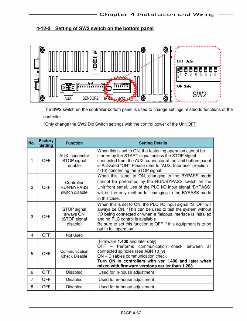
Chapter 4 Installation and Wiring
PAGE 4-67
4-12-3 Setting of SW2 switch on the bottom panel
The SW2 switch on the controller bottom panel is used to change settings related to functions of the
controller.
*Only change the SW2 Dip Switch settings with the control power of the Unit OFF.
No. Factory Setting
Function Setting Details
1 OFF AUX. connector
STOP signal enable
When this is set to ON, the fastening operation cannot be started by the START signal unless the STOP signal connected from the AUX. connector at the Unit bottom panel is Activated “ON”. Please refer to “AUX. Interface” (Section 4-10) concerning the STOP signal.
2 OFF Controller
RUN/BYPASS switch disable
When this is set to ON, changing to the BYPASS mode
cannot be performed by the RUN/BYPASS switch on the
Unit front panel. Use of the PLC I/O input signal “BYPASS”
will be the only method for changing to the BYPASS mode
in this case.
3 OFF
STOP signal always ON
(STOP signal disable)
When this is set to ON, the PLC I/O input signal “STOP” will always be ON. *This can be used to test the system without I/O being connected or when a fieldbus interface is installed and no PLC control is available Be sure to set this function to OFF if this equipment is to be put in full operation.
4 OFF Not Used
5 OFF Communication
Check Disable
(Firmware 1.400 and later only) OFF – Performs communication check between all connected spindles (see ABN 10_9) ON – Disables communication check Turn ON in controllers with ver 1.400 and later when mixed with firmware versions earlier than 1.283
6 OFF Disabled Used for in-house adjustment
7 OFF Disabled Used for in-house adjustment
8 OFF Disabled Used for in-house adjustment
OFF SideOFF SideOFF SideOFF Side ON SideON SideON SideON Side

Chapter 4 Installation and Wiring
PAGE 4-68
(Blank Page)

Chapter 5 I/O Expansion Unit
Page 5-1
Chapter 5: I/O Expansion Unit
5
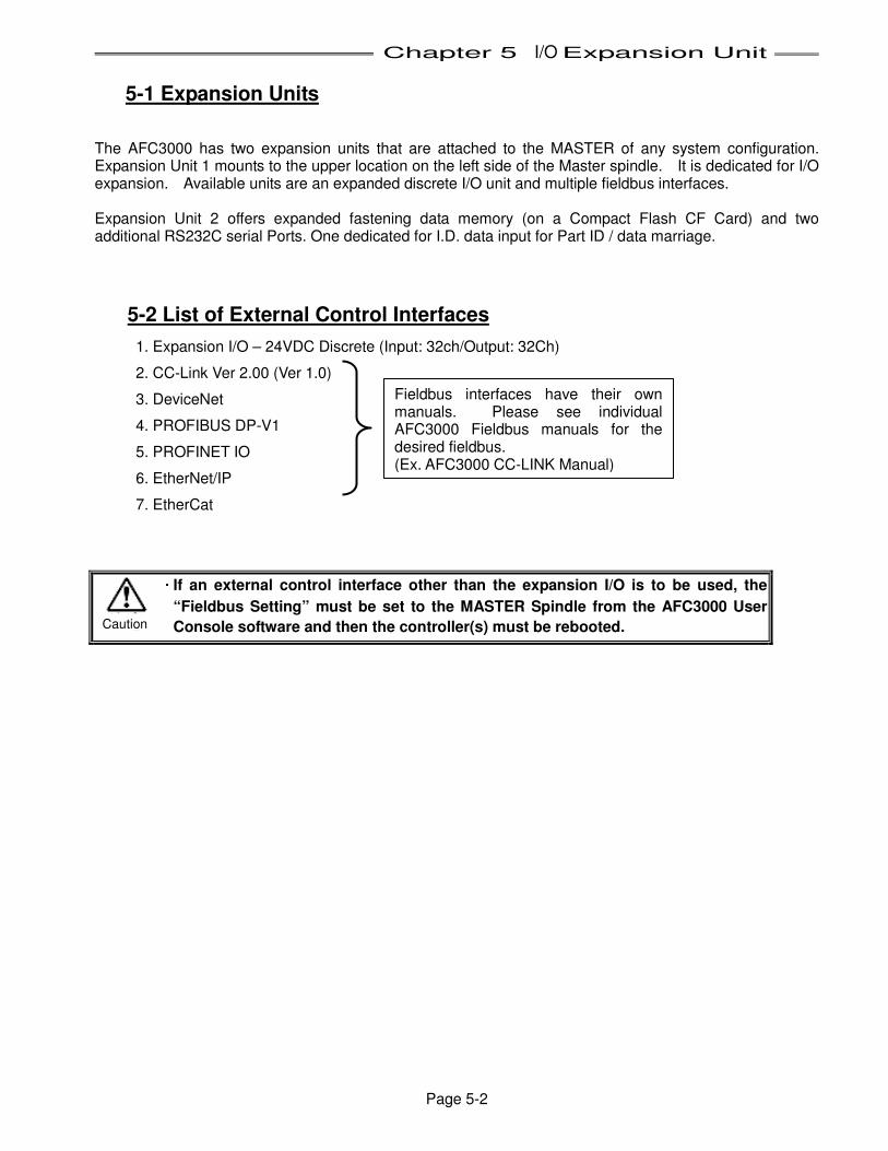
Chapter 5 I/O Expansion Unit
Page 5-2
5-1 Expansion Units
The AFC3000 has two expansion units that are attached to the MASTER of any system configuration. Expansion Unit 1 mounts to the upper location on the left side of the Master spindle. It is dedicated for I/O expansion. Available units are an expanded discrete I/O unit and multiple fieldbus interfaces. Expansion Unit 2 offers expanded fastening data memory (on a Compact Flash CF Card) and two additional RS232C serial Ports. One dedicated for I.D. data input for Part ID / data marriage.
5-2 List of External Control Interfaces
1. Expansion I/O – 24VDC Discrete (Input: 32ch/Output: 32Ch)
2. CC-Link Ver 2.00 (Ver 1.0)
3. DeviceNet
4. PROFIBUS DP-V1
5. PROFINET IO
6. EtherNet/IP
7. EtherCat
・・・・ If an external control interface other than the expansion I/O is to be used, the
“Fieldbus Setting” must be set to the MASTER Spindle from the AFC3000 User
Console software and then the controller(s) must be rebooted. Caution
Fieldbus interfaces have their own manuals. Please see individual AFC3000 Fieldbus manuals for the desired fieldbus. (Ex. AFC3000 CC-LINK Manual)
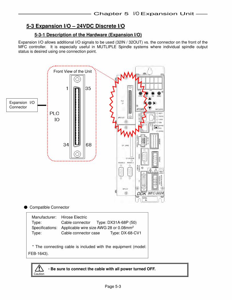
Chapter 5 I/O Expansion Unit
Page 5-3
5-3 Expansion I/O – 24VDC Discrete I/O
5-3-1 Description of the Hardware (Expansion I/O)
Expansion I/O allows additional I/O signals to be used (32IN / 32OUT) vs. the connector on the front of the MFC controller. It is especially useful in MUTLIPLE Spindle systems where individual spindle output status is desired using one connection point.
● Compatible Connector
Manufacturer: Hirose Electric
Type: Cable connector Type: DX31A-68P (50)
Specifications: Applicable wire size AWG 28 or 0.08mm2
Type: Cable connector case Type: DX-68-CV1
* The connecting cable is included with the equipment (model:
FEB-1643).
・・・・ Be sure to connect the cable with all power turned OFF.
Expansion I/O
Connector Front View of the Unit
Caution
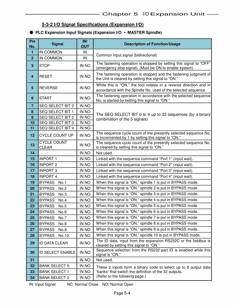
Chapter 5 I/O Expansion Unit
Page 5-4
5-3-2 I/O Signal Specifications (Expansion I/O) ● PLC Expansion Input Signals (Expansion I/O →→→→ MASTER Spindle)
IN: Input Signal NC: Normal Close NO: Normal Open
Pin
No. Signal
IN/
OUT Description of Function/Usage
1 IN COMMON IN Common input signal (bidirectional)
2 IN COMMON IN
3 STOP IN NC The fastening operation is stopped by setting this signal to “OFF” (emergency stop signal). (Must be ON to enable system)
4 RESET IN NO The fastening operation is stopped and the fastening judgment of the Unit is cleared by setting this signal to “ON.”
5 REVERSE IN NO While this is “ON,” the tool rotates in a reverse direction and in
accordance with the Spindle No. used of the selected sequence
6 START IN NO The fastening operation in accordance with the selected sequence
No. is started by setting this signal to “ON.”
7 SEQ SELECT BIT 0 IN NO
The SEQ SELECT BIT 0 to 4 up to 32 sequences (by a binary combination of the 5 signals)
8 SEQ SELECT BIT 1 IN NO
9 SEQ SELECT BIT 2 IN NO
10 SEQ SELECT BIT 3 IN NO
11 SEQ SELECT BIT 4 IN NO
12 CYCLE COUNT UP IN NO The sequence cycle count of the presently selected sequence No. is incremented by 1 by setting this signal to “ON.”
13 CYCLE COUNT
CLEAR IN NO
The sequence cycle count of the presently selected sequence No. is cleared by setting this signal to “ON.”
14 IN NO Not used.
15 INPORT 1 IN NO Linked with the sequence command “Port 1” (input wait).
16 INPORT 2 IN NO Linked with the sequence command “Port 2” (input wait).
17 INPORT 3 IN NO Linked with the sequence command “Port 3” (input wait).
18 INPORT 4 IN NO Linked with the sequence command “Port 4” (input wait).
19 BYPASS No.1 IN NO When this signal is “ON,” spindle 1 is put in BYPASS mode.
20 BYPASS No.2 IN NO When this signal is “ON,” spindle 2 is put in BYPASS mode.
21 BYPASS No.3 IN NO When this signal is “ON,” spindle 3 is put in BYPASS mode.
22 BYPASS No.4 IN NO When this signal is “ON,” spindle 4 is put in BYPASS mode.
23 BYPASS No.5 IN NO When this signal is “ON,” spindle 5 is put in BYPASS mode.
24 BYPASS No.6 IN NO When this signal is “ON,” spindle 6 is put in BYPASS mode.
25 BYPASS No.7 IN NO When this signal is “ON,” spindle 7 is put in BYPASS mode.
26 BYPASS No.8 IN NO When this signal is “ON,” spindle 8 is put in BYPASS mode.
27 BYPASS No.9 IN NO When this signal is “ON,” spindle 9 is put in BYPASS mode.
28 BYPASS No.10 IN NO When this signal is “ON,” spindle 10 is put in BYPASS mode.
29 ID DATA CLEAR IN NO The ID data, input from the expansion RS232C or the fieldbus is cleared by setting this signal to “ON.”
30 ID SELECT ENABLE IN NO Sequence selection from the RS232 part ID is enabled while this signal is “ON.”
31 IN NO Not used.
32 BANK SELECT 0 IN NO These 2 inputs form a binary code to select up to 8 output data “banks” that switch the definition of the 32 outputs. (Refer to the following page.)
33 BANK SELECT 1 IN NO
34 BANK SELECT 2 IN NO
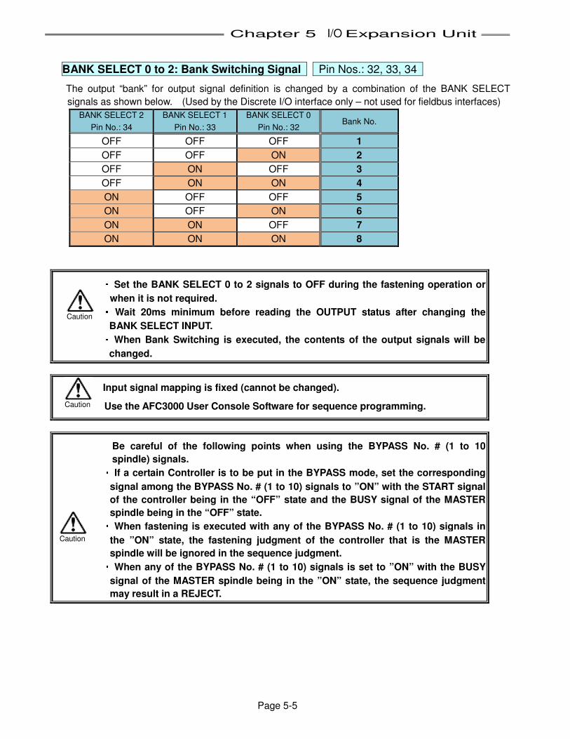
Chapter 5 I/O Expansion Unit
Page 5-5
BANK SELECT 0 to 2: Bank Switching Signal Pin Nos.: 32, 33, 34
The output “bank” for output signal definition is changed by a combination of the BANK SELECT
signals as shown below. (Used by the Discrete I/O interface only – not used for fieldbus interfaces)
BANK SELECT 2
Pin No.: 34 BANK SELECT 1
Pin No.: 33 BANK SELECT 0
Pin No.: 32 Bank No. OFF OFF OFF 1
OFF OFF ON 2
OFF ON OFF 3
OFF ON ON 4
ON OFF OFF 5
ON OFF ON 6
ON ON OFF 7
ON ON ON 8
・・・・ Set the BANK SELECT 0 to 2 signals to OFF during the fastening operation or
when it is not required. ・・・・ Wait 20ms minimum before reading the OUTPUT status after changing the
BANK SELECT INPUT. ・・・・ When Bank Switching is executed, the contents of the output signals will be
changed. Input signal mapping is fixed (cannot be changed).
Use the AFC3000 User Console Software for sequence programming. Be careful of the following points when using the BYPASS No. # (1 to 10
spindle) signals. ・・・・ If a certain Controller is to be put in the BYPASS mode, set the corresponding
signal among the BYPASS No. # (1 to 10) signals to ”ON” with the START signal
of the controller being in the “OFF” state and the BUSY signal of the MASTER
spindle being in the “OFF” state. ・・・・ When fastening is executed with any of the BYPASS No. # (1 to 10) signals in
the ”ON” state, the fastening judgment of the controller that is the MASTER
spindle will be ignored in the sequence judgment. ・・・・ When any of the BYPASS No. # (1 to 10) signals is set to ”ON” with the BUSY
signal of the MASTER spindle being in the ”ON” state, the sequence judgment
may result in a REJECT.
Caution Caution
Caution
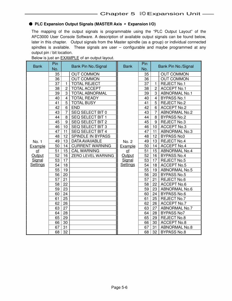
Chapter 5 I/O Expansion Unit
Page 5-6
● PLC Expansion Output Signals (MASTER Axis →→→→ Expansion I/O)
The mapping of the output signals is programmable using the “PLC Output Layout” of the
AFC3000 User Console Software. A description of available output signals can be found below,
later in this chapter. Output signals from the Master spindle (as a group) or individual connected
spindles is available. These signals are user – configurable and maybe programmed at any
output pin / bit location.
Below is just an EXAMPLE of an output layout.
Bank Pin No.
Bank Pin No./Signal Bank Pin No.
Bank Pin No./Signal
No. 1 Example
of Output Signal
Settings
35 OUT COMMON
No. 2 Example
of Output Signal
Settings
35 OUT COMMON 36 OUT COMMON 36 OUT COMMON 37 1 TOTAL REJECT 37 1 REJECT No.1 38 2 TOTAL ACCEPT 38 2 ACCEPT No.1 39 3 TOTAL ABNORMAL 39 3 ABNORMAL No.1 40 4 TOTAL READY 40 4 BYPASS No.1 41 5 TOTAL BUSY 41 5 REJECT No.2 42 6 END 42 6 ACCEPT No.2 43 7 SEQ SELECT BIT 0 43 7 ABNORMAL No.2 44 8 SEQ SELECT BIT 1 44 8 BYPASS No.2 45 9 SEQ SELECT BIT 2 45 9 REJECT No.3 46 10 SEQ SELECT BIT 3 46 10 ACCEPT No.3 47 11 SEQ SELECT BIT 4 47 11 ABNORMAL No.3 48 12 SPINDLE IN BYPASS 48 12 BYPASS No3 49 13 DATA AVAIIABLE 49 13 REJECT No.4 50 14 CURRENT WARNING 50 14 ACCEPT No.4
51 15 CAL WARNING 51 15 ABNORMAL No.4 52 16 ZERO LEVEL WARNING 52 16 BYPASS No.4 53 17 53 17 REJECT No.5 54 18 54 18 ACCEPT No.5 55 19 55 19 ABNORMAL No.5 56 20 56 20 BYPASS No.5 57 21 57 21 REJECT No.6 58 22 58 22 ACCEPT No.6 59 23 59 23 ABNORMAL No.6 60 24 60 24 BYPASS No.6 61 25 61 25 REJECT No.7 62 26 62 26 ACCEPT No.7 63 27 63 27 ABNORMAL No.7 64 28 64 28 BYPASS No7 65 29 65 29 REJECT No.8 66 30 66 30 ACCEPT No.8 67 31 67 31 ABNORMAL No.8 68 32 68 32 BYPASS No.8
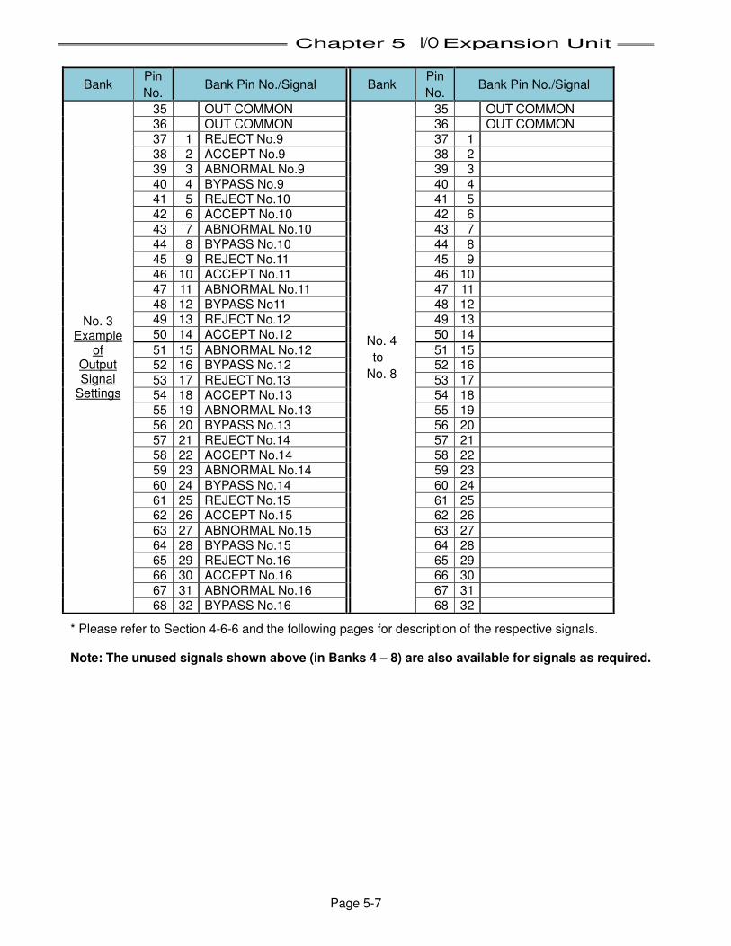
Chapter 5 I/O Expansion Unit
Page 5-7
Bank
Pin No.
Bank Pin No./Signal Bank Pin No.
Bank Pin No./Signal
No. 3 Example
of Output Signal
Settings
35 OUT COMMON
No. 4
to
No. 8
35 OUT COMMON 36 OUT COMMON 36 OUT COMMON 37 1 REJECT No.9 37 1 38 2 ACCEPT No.9 38 2 39 3 ABNORMAL No.9 39 3 40 4 BYPASS No.9 40 4 41 5 REJECT No.10 41 5 42 6 ACCEPT No.10 42 6 43 7 ABNORMAL No.10 43 7 44 8 BYPASS No.10 44 8 45 9 REJECT No.11 45 9 46 10 ACCEPT No.11 46 10 47 11 ABNORMAL No.11 47 11 48 12 BYPASS No11 48 12 49 13 REJECT No.12 49 13 50 14 ACCEPT No.12 50 14
51 15 ABNORMAL No.12 51 15 52 16 BYPASS No.12 52 16 53 17 REJECT No.13 53 17 54 18 ACCEPT No.13 54 18 55 19 ABNORMAL No.13 55 19 56 20 BYPASS No.13 56 20 57 21 REJECT No.14 57 21 58 22 ACCEPT No.14 58 22 59 23 ABNORMAL No.14 59 23 60 24 BYPASS No.14 60 24 61 25 REJECT No.15 61 25 62 26 ACCEPT No.15 62 26 63 27 ABNORMAL No.15 63 27 64 28 BYPASS No.15 64 28 65 29 REJECT No.16 65 29 66 30 ACCEPT No.16 66 30 67 31 ABNORMAL No.16 67 31 68 32 BYPASS No.16 68 32
* Please refer to Section 4-6-6 and the following pages for description of the respective signals.
Note: The unused signals shown above (in Banks 4 – 8) are also available for signals as required.
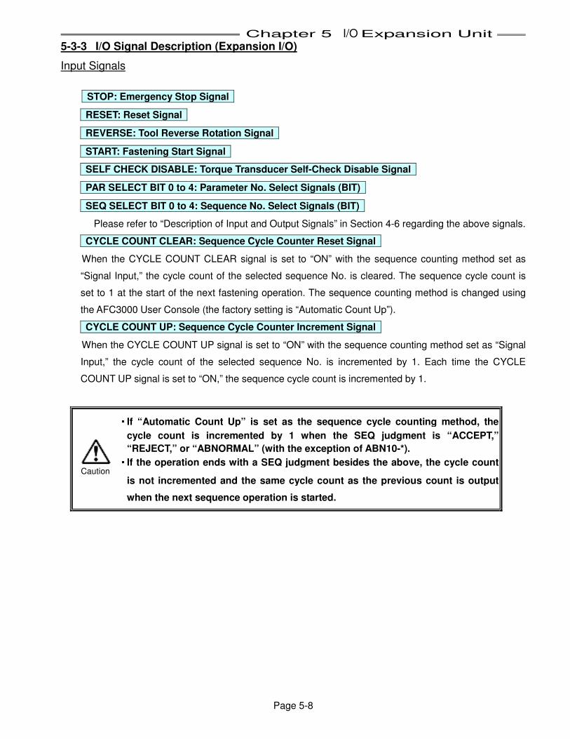
Chapter 5 I/O Expansion Unit
Page 5-8
5-3-3 I/O Signal Description (Expansion I/O)
Input Signals
STOP: Emergency Stop Signal
RESET: Reset Signal
REVERSE: Tool Reverse Rotation Signal
START: Fastening Start Signal
SELF CHECK DISABLE: Torque Transducer Self-Check Disable Signal
PAR SELECT BIT 0 to 4: Parameter No. Select Signals (BIT)
SEQ SELECT BIT 0 to 4: Sequence No. Select Signals (BIT)
Please refer to “Description of Input and Output Signals” in Section 4-6 regarding the above signals.
CYCLE COUNT CLEAR: Sequence Cycle Counter Reset Signal
When the CYCLE COUNT CLEAR signal is set to “ON” with the sequence counting method set as
“Signal Input,” the cycle count of the selected sequence No. is cleared. The sequence cycle count is
set to 1 at the start of the next fastening operation. The sequence counting method is changed using
the AFC3000 User Console (the factory setting is “Automatic Count Up”).
CYCLE COUNT UP: Sequence Cycle Counter Increment Signal
When the CYCLE COUNT UP signal is set to “ON” with the sequence counting method set as “Signal
Input,” the cycle count of the selected sequence No. is incremented by 1. Each time the CYCLE
COUNT UP signal is set to “ON,” the sequence cycle count is incremented by 1.
・・・・ If “Automatic Count Up” is set as the sequence cycle counting method, the
cycle count is incremented by 1 when the SEQ judgment is “ACCEPT,”
“REJECT,” or “ABNORMAL” (with the exception of ABN10-*). ・・・・ If the operation ends with a SEQ judgment besides the above, the cycle count
is not incremented and the same cycle count as the previous count is output
when the next sequence operation is started.
Caution
Chapter 5 I/O Expansion Unit
Page 5-9
INPORT 1 to 4: External Sequence Input Signal
These four signals are external inputs to the internal fastening sequence. When a [PLC INPUT
WAIT] instruction is programmed in the fastening sequence, the sequence will stop until the one of
these inputs is active (ON). (The input number 1-4 is programmed in the sequence desiganating
which signal to use)
ID DATA CLEAR: Unit ID Data Clear Signal
When the ID DATA CLEAR signal is set “ON,” the ID data input from the RS232C (or the fieldbus
message) is cleared. The fastening judgment and fastening data will not be cleared by the ID DATA
CLEAR signal. Also, if the next fastening operation is started in the state where the ID data is not
input (after being cleared), the data is filled with ASCII 20H: “space”.
The ID data is held in the Unit until the ID DATA CLEAR signal is set to ON or the next DATA is input
to the RS232 port (or the fieldbus message).
BYPASS No # (1 to 32): 1st - 32nd Spindle Bypass Signal
When a BYPASS No. # (1 to 32) signal is set “ON,” the controller of the selected spindle No. is put in
BYPASS mode and will not start the fastening operation. (The spindle will be ignored if in a MULTI
spindle configuration.
When switching to the BYPASS mode is performed while the fastening operation is in cycle, the
fastening operation will stop and the fastening data up to the point of stopping will be held.
ID SELECT ENABLE: Sequence Select by Part ID enabled
When the ID SELECT ENABLE signal is set “ON,” it enables the function to select the sequence from
the part ID data. In conjunction with this input, it also has to be setup in the AFC3000 User Console
software where the “Input from ID Data,” is selected in the “RS232C Input Format/Data Input Setup”
screen. The sequence can be selected by the ID code (ASCII letters, 32 letters at max.) input from
the RS232C-2 (Or fieldbus message) of the Expansion Unit 2.
If the ID SELECT ENABLE signal is “OFF” the sequence selection is selected from the Sequence
select inputs (PLC I/O).
IND SEQ SELECT No. ENABLE: Individual Sequence No. Select Enable Signal**
When the SEQ SELECT No. ENABLE signal is set “ON”, the individual SEQ SELECT No. # (1 to 32)
signals are used to select the sequence number. This makes it easier than selecting sequences
using the binary coded sequence select bits.
If the SEQ SELECT BIT 0 to 4 signals are to be used to select the sequence No., confirm the SEQ
SELECT No. ENABLE signal is “OFF.”
SEQ SELECT No. # (1 to 32): Sequence No. Select Signal (Individual)**
When IND SEQ SELECT is enabled, (32) individual sequence select inputs are available for
sequence selection (SEQ SELECT 1, SEQ SELECT2… SEQ SELECT 32)
**AVAILABLE FOR FIELDBUS ONLY
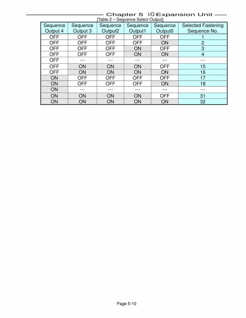
Chapter 5 I/O Expansion Unit
Page 5-10
[Table 2 – Sequence Select Output]
Sequence Output 4
Sequence Output 3
Sequence Output2
Sequence Output1
Sequence Output0
Selected Fastening Sequence No.
OFF OFF OFF OFF OFF 1 OFF OFF OFF OFF ON 2 OFF OFF OFF ON OFF 3
OFF OFF OFF ON ON 4 OFF … … … … …
OFF ON ON ON OFF 15 OFF ON ON ON ON 16 ON OFF OFF OFF OFF 17 ON OFF OFF OFF ON 18
ON … … … … …
ON ON ON ON OFF 31 ON ON ON ON ON 32
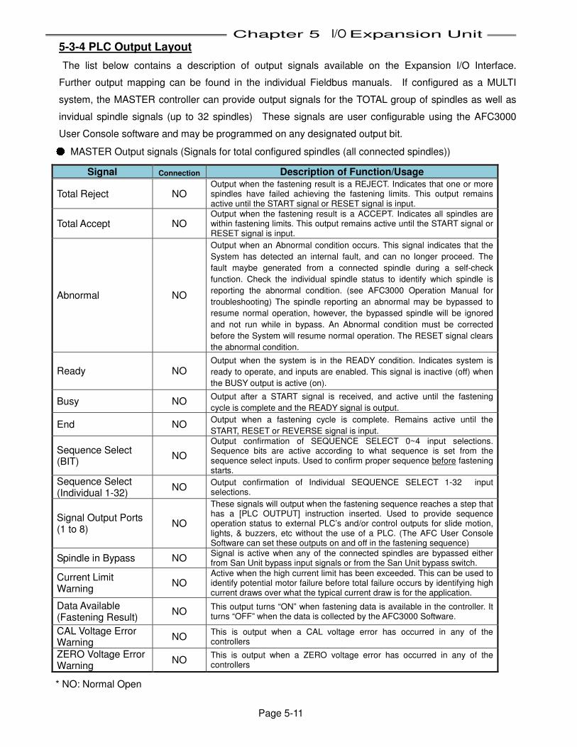
Chapter 5 I/O Expansion Unit
Page 5-11
5-3-4 PLC Output Layout
The list below contains a description of output signals available on the Expansion I/O Interface.
Further output mapping can be found in the individual Fieldbus manuals. If configured as a MULTI
system, the MASTER controller can provide output signals for the TOTAL group of spindles as well as
invidual spindle signals (up to 32 spindles) These signals are user configurable using the AFC3000
User Console software and may be programmed on any designated output bit. ● MASTER Output signals (Signals for total configured spindles (all connected spindles))
Signal Connection Description of Function/Usage
Total Reject NO Output when the fastening result is a REJECT. Indicates that one or more spindles have failed achieving the fastening limits. This output remains active until the START signal or RESET signal is input.
Total Accept NO Output when the fastening result is a ACCEPT. Indicates all spindles are within fastening limits. This output remains active until the START signal or RESET signal is input.
Abnormal NO
Output when an Abnormal condition occurs. This signal indicates that the
System has detected an internal fault, and can no longer proceed. The
fault maybe generated from a connected spindle during a self-check
function. Check the individual spindle status to identify which spindle is
reporting the abnormal condition. (see AFC3000 Operation Manual for
troubleshooting) The spindle reporting an abnormal may be bypassed to
resume normal operation, however, the bypassed spindle will be ignored
and not run while in bypass. An Abnormal condition must be corrected
before the System will resume normal operation. The RESET signal clears
the abnormal condition.
Ready NO Output when the system is in the READY condition. Indicates system is
ready to operate, and inputs are enabled. This signal is inactive (off) when
the BUSY output is active (on).
Busy NO Output after a START signal is received, and active until the fastening
cycle is complete and the READY signal is output.
End NO Output when a fastening cycle is complete. Remains active until the
START, RESET or REVERSE signal is input.
Sequence Select (BIT)
NO
Output confirmation of SEQUENCE SELECT 0~4 input selections. Sequence bits are active according to what sequence is set from the sequence select inputs. Used to confirm proper sequence before fastening starts.
Sequence Select (Individual 1-32)
NO Output confirmation of Individual SEQUENCE SELECT 1-32 input selections.
Signal Output Ports (1 to 8)
NO
These signals will output when the fastening sequence reaches a step that has a [PLC OUTPUT] instruction inserted. Used to provide sequence operation status to external PLC’s and/or control outputs for slide motion, lights, & buzzers, etc without the use of a PLC. (The AFC User Console Software can set these outputs on and off in the fastening sequence)
Spindle in Bypass NO Signal is active when any of the connected spindles are bypassed either from San Unit bypass input signals or from the San Unit bypass switch.
Current Limit Warning
NO Active when the high current limit has been exceeded. This can be used to identify potential motor failure before total failure occurs by identifying high current draws over what the typical current draw is for the application.
Data Available (Fastening Result)
NO This output turns “ON” when fastening data is available in the controller. It turns “OFF” when the data is collected by the AFC3000 Software.
CAL Voltage Error Warning
NO This is output when a CAL voltage error has occurred in any of the controllers
ZERO Voltage Error Warning
NO This is output when a ZERO voltage error has occurred in any of the controllers
* NO: Normal Open
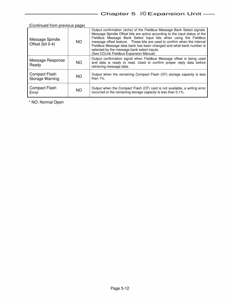
Chapter 5 I/O Expansion Unit
Page 5-12
(Continued from previous page)
Message Spindle Offset (bit 0-4)
NO
Output confirmation (echo) of the Fieldbus Message Bank Select signals. Message Spindle Offset bits are active according to the input status of the Fieldbus Message Bank Select Input bits when using the Fieldbus message offset feature. These bits are used to confirm when the internal Fieldbus Message data bank has been changed and what bank number is selected by the message bank select inputs. (See CCLink Fieldbus Expansion Manual)
Message Response Ready
NO Output confirmation signal when Fieldbus Message offset is being used and data is ready to read. Used to confirm proper reply data before retrieving message data.
Compact Flash Storage Warning
NO Output when the remaining Compact Flash (CF) storage capacity is less than 1%.
Compact Flash Error
NO Output when the Compact Flash (CF) card is not available, a writing error occurred or the remaining storage capacity is less than 0.1%.
* NO: Normal Open
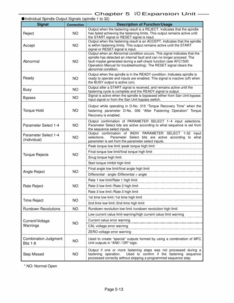
Chapter 5 I/O Expansion Unit
Page 5-13
●Individual Spindle Output Signals (spindle 1 to 32)
Signal Connection Description of Function/Usage
Reject NO Output when the fastening result is a REJECT. Indicates that the spindle has failed achieving the fastening limits. This output remains active until the START signal or RESET signal is input.
Accept NO Output when the fastening result is an ACCEPT. Indicates that the spindle is within fastening limits. This output remains active until the START signal or RESET signal is input.
Abnormal NO
Output when an Abnormal condition occurs. This signal indicates that the spindle has detected an internal fault and can no longer proceed. The fault maybe generated during a self-check function (see AFC1500 Operation Manual for troubleshooting). The RESET signal clears the abnormal condition.
Ready NO Output when the spindle is in the READY condition. Indicates spindle is ready to operate and inputs are enabled. This signal is inactive (off) when the BUSY output is active (on).
Busy NO Output after a START signal is received, and remains active until the fastening cycle is complete and the READY signal is output.
Bypass NO Signal is active when the spindle is bypassed either from San Unit bypass input signal or from the San Unit bypass switch.
Torque Hold NO Output while operating in D-No. 315 “Torque Recovery Time” when the
fastening parameter D-No. 006 “After Fastening Operation” Torque
Recovery is enabled.
Parameter Select 1-4 NO Output confirmation of PARAMETER SELECT 1~4 input selections. Parameter Select bits are active according to what sequence is set from the sequence select inputs.
Parameter Select 1-4
(Individual) NO
Output confirmation of INDIV PARAMETER SELECT 1-32 input selections. Parameter Select bits are active according to what parameter is set from the parameter select inputs.
Torque Rejects NO
Peak torque low limit /peak torque high limit
Final torque low limit/final torque high limit
Snug torque high limit
Start torque inhibit high limit
Angle Reject NO Final angle low limit/final angle high limit
Differential - angle /Differential + angle
Rate Reject NO
Rate 1 low limit/Rate 1 high limit
Rate 2 low limit /Rate 2 high limit
Rate 3 low limit /Rate 3 high limit
Time Reject NO 1st time low limit /1st time high limit
2nd time low limit /2nd time high limit
Rundown Revolutions NO Rundown revolution low limit /rundown revolution high limit
Current/Voltage
Warnings NO
Low current value limit warning/high current value limit warning
Current value error warning
CAL voltage error warning
ZERO voltage error warning
Combination Judgment
Bits 1-8 NO
Used to create “special” outputs formed by using a combination of MFC Unit outputs in “AND / OR” logic.
Step Missed NO Output if one or more fastening steps was not processed during a fastening operation. Used to confirm if the fastening sequence processed correctly without skipping a programmed sequence step.
* NO: Normal Open
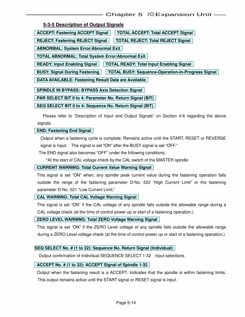
Chapter 5 I/O Expansion Unit
Page 5-14
5-3-5 Description of Output Signals
ACCEPT: Fastening ACCEPT Signal TOTAL ACCEPT: Total ACCEPT Signal
REJECT: Fastening REJECT Signal TOTAL REJECT: Total REJECT Signal
ABNORMAL: System Error/Abnormal Exit
TOTAL ABNORMAL: Total System Error/Abnormal Exit
READY: Input Enabling Signal TOTAL READY: Total Input Enabling Signal
BUSY: Signal During Fastening TOTAL BUSY: Sequence-Operation-in-Progress Signal
DATA AVAILABLE: Fastening Result Data are Available
SPINDLE IN BYPASS: BYPASS Axis Detection Signal
PAR SELECT BIT 0 to 4: Parameter No. Return Signal (BIT)
SEQ SELECT BIT 0 to 4: Sequence No. Return Signal (BIT)
Please refer to “Description of Input and Output Signals” on Section 4-6 regarding the above
signals.
END: Fastening End Signal
Output when a fastening cycle is complete. Remains active until the START, RESET or REVERSE
signal is input. The signal is set “ON” after the BUSY signal is set “OFF.”
The END signal also becomes “OFF” under the following conditions;
*At the start of CAL voltage check by the CAL switch of the MASTER spindle
CURRENT WARNING: Total Current Value Warning Signal
This signal is set “ON” when, any spindle peak current value during the fastening operation falls
outside the range of the fastening parameter D-No. 522 “High Current Limit” or the fastening
parameter D-No. 521 “Low Current Limit.”
CAL WARNING: Total CAL Voltage Warning Signal
This signal is set “ON” if the CAL voltage of any spindle falls outside the allowable range during a
CAL voltage check (at the time of control power up or start of a fastening operation.)
ZERO LEVEL WARNING: Total ZERO Voltage Warning Signal
This signal is set “ON” if the ZERO Level voltage of any spindle falls outside the allowable range
during a ZERO Level voltage check (at the time of control power up or start of a fastening operation.)
SEQ SELECT No. # (1 to 32): Sequence No. Return Signal (Individual)
Output confirmation of Individual SEQUENCE SELECT 1-32 input selections.
ACCEPT No. # (1 to 32): ACCEPT Signal of Spindle 1-32
Output when the fastening result is a ACCEPT. Indicates that the spindle is within fastening limits.
This output remains active until the START signal or RESET signal is input.
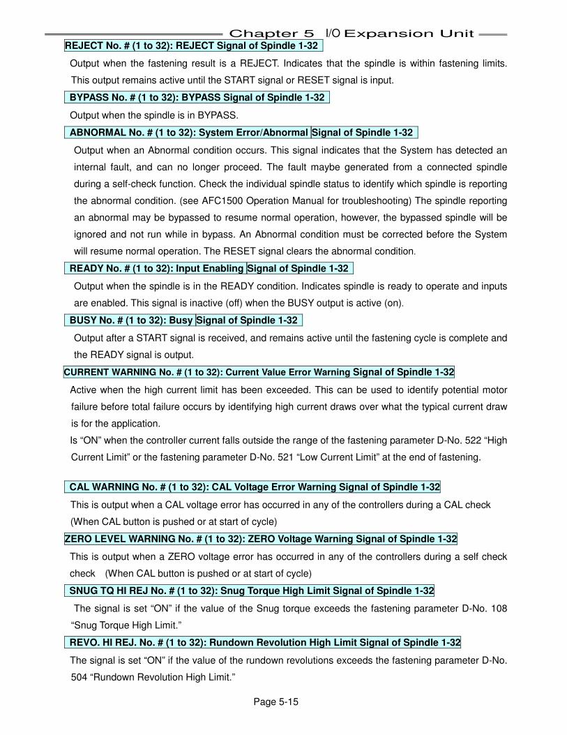
Chapter 5 I/O Expansion Unit
Page 5-15
REJECT No. # (1 to 32): REJECT Signal of Spindle 1-32
Output when the fastening result is a REJECT. Indicates that the spindle is within fastening limits.
This output remains active until the START signal or RESET signal is input.
BYPASS No. # (1 to 32): BYPASS Signal of Spindle 1-32
Output when the spindle is in BYPASS.
ABNORMAL No. # (1 to 32): System Error/Abnormal Signal of Spindle 1-32
Output when an Abnormal condition occurs. This signal indicates that the System has detected an
internal fault, and can no longer proceed. The fault maybe generated from a connected spindle
during a self-check function. Check the individual spindle status to identify which spindle is reporting
the abnormal condition. (see AFC1500 Operation Manual for troubleshooting) The spindle reporting
an abnormal may be bypassed to resume normal operation, however, the bypassed spindle will be
ignored and not run while in bypass. An Abnormal condition must be corrected before the System
will resume normal operation. The RESET signal clears the abnormal condition.
READY No. # (1 to 32): Input Enabling Signal of Spindle 1-32
Output when the spindle is in the READY condition. Indicates spindle is ready to operate and inputs
are enabled. This signal is inactive (off) when the BUSY output is active (on).
BUSY No. # (1 to 32): Busy Signal of Spindle 1-32
Output after a START signal is received, and remains active until the fastening cycle is complete and
the READY signal is output.
CURRENT WARNING No. # (1 to 32): Current Value Error Warning Signal of Spindle 1-32
Active when the high current limit has been exceeded. This can be used to identify potential motor
failure before total failure occurs by identifying high current draws over what the typical current draw
is for the application.
Is “ON” when the controller current falls outside the range of the fastening parameter D-No. 522 “High
Current Limit” or the fastening parameter D-No. 521 “Low Current Limit” at the end of fastening. CAL WARNING No. # (1 to 32): CAL Voltage Error Warning Signal of Spindle 1-32
This is output when a CAL voltage error has occurred in any of the controllers during a CAL check
(When CAL button is pushed or at start of cycle)
ZERO LEVEL WARNING No. # (1 to 32): ZERO Voltage Warning Signal of Spindle 1-32
This is output when a ZERO voltage error has occurred in any of the controllers during a self check
check (When CAL button is pushed or at start of cycle)
SNUG TQ HI REJ No. # (1 to 32): Snug Torque High Limit Signal of Spindle 1-32
The signal is set “ON” if the value of the Snug torque exceeds the fastening parameter D-No. 108
“Snug Torque High Limit.”
REVO. HI REJ. No. # (1 to 32): Rundown Revolution High Limit Signal of Spindle 1-32
The signal is set “ON” if the value of the rundown revolutions exceeds the fastening parameter D-No.
504 “Rundown Revolution High Limit.”
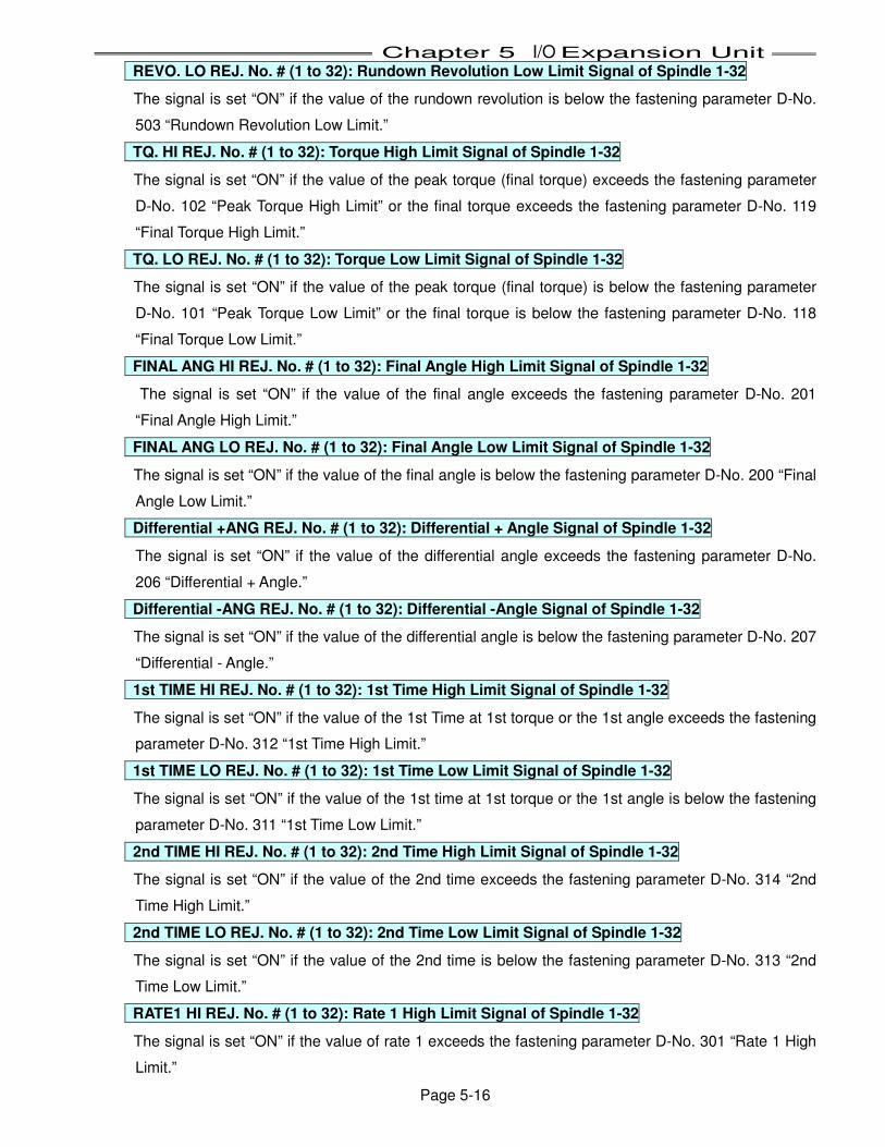
Chapter 5 I/O Expansion Unit
Page 5-16
REVO. LO REJ. No. # (1 to 32): Rundown Revolution Low Limit Signal of Spindle 1-32
The signal is set “ON” if the value of the rundown revolution is below the fastening parameter D-No.
503 “Rundown Revolution Low Limit.”
TQ. HI REJ. No. # (1 to 32): Torque High Limit Signal of Spindle 1-32
The signal is set “ON” if the value of the peak torque (final torque) exceeds the fastening parameter
D-No. 102 “Peak Torque High Limit” or the final torque exceeds the fastening parameter D-No. 119
“Final Torque High Limit.”
TQ. LO REJ. No. # (1 to 32): Torque Low Limit Signal of Spindle 1-32
The signal is set “ON” if the value of the peak torque (final torque) is below the fastening parameter
D-No. 101 “Peak Torque Low Limit” or the final torque is below the fastening parameter D-No. 118
“Final Torque Low Limit.”
FINAL ANG HI REJ. No. # (1 to 32): Final Angle High Limit Signal of Spindle 1-32
The signal is set “ON” if the value of the final angle exceeds the fastening parameter D-No. 201
“Final Angle High Limit.”
FINAL ANG LO REJ. No. # (1 to 32): Final Angle Low Limit Signal of Spindle 1-32
The signal is set “ON” if the value of the final angle is below the fastening parameter D-No. 200 “Final
Angle Low Limit.”
Differential +ANG REJ. No. # (1 to 32): Differential + Angle Signal of Spindle 1-32
The signal is set “ON” if the value of the differential angle exceeds the fastening parameter D-No.
206 “Differential + Angle.”
Differential -ANG REJ. No. # (1 to 32): Differential -Angle Signal of Spindle 1-32
The signal is set “ON” if the value of the differential angle is below the fastening parameter D-No. 207
“Differential - Angle.”
1st TIME HI REJ. No. # (1 to 32): 1st Time High Limit Signal of Spindle 1-32
The signal is set “ON” if the value of the 1st Time at 1st torque or the 1st angle exceeds the fastening
parameter D-No. 312 “1st Time High Limit.”
1st TIME LO REJ. No. # (1 to 32): 1st Time Low Limit Signal of Spindle 1-32
The signal is set “ON” if the value of the 1st time at 1st torque or the 1st angle is below the fastening
parameter D-No. 311 “1st Time Low Limit.”
2nd TIME HI REJ. No. # (1 to 32): 2nd Time High Limit Signal of Spindle 1-32
The signal is set “ON” if the value of the 2nd time exceeds the fastening parameter D-No. 314 “2nd
Time High Limit.”
2nd TIME LO REJ. No. # (1 to 32): 2nd Time Low Limit Signal of Spindle 1-32
The signal is set “ON” if the value of the 2nd time is below the fastening parameter D-No. 313 “2nd
Time Low Limit.”
RATE1 HI REJ. No. # (1 to 32): Rate 1 High Limit Signal of Spindle 1-32
The signal is set “ON” if the value of rate 1 exceeds the fastening parameter D-No. 301 “Rate 1 High
Limit.”
Chapter 5 I/O Expansion Unit
Page 5-17
RATE1 LO REJ. No. # (1 to 32): Rate 1 Low Limit Signal of Spindle 1-32
The signal is set “ON” if the value of rate 1 is below the fastening parameter D-No. 300 “Rate 1 Low
Limit.”
RATE2 HI REJ. No. # (1 to 32): Rate 2 High Limit Signal of Spindle 1-32
The signal is set “ON” if the value of rate 2 exceeds the fastening parameter D-No. 303 “Rate 2 High
Limit.” RATE2 LO REJ. No. # (1 to 32): Rate 2 Low Limit Signal of Spindle 1-32
The signal is set “ON” if the value of rate 2 is below the fastening parameter D-No. 302 “Rate 2 Low
Limit.”
RATE3 HI REJ. No. # (1 to 32): Rate 3 High Limit Signal of Spindle 1-32
The signal is set “ON” if the value of rate 3 exceeds the fastening parameter D-No. 305 “Rate 3 High
Limit.”
RATE3 LO REJ. No. # (1 to 32): Rate 3 Low Limit Signal of Spindle 1-32
The signal is set “ON” if the value of rate 3 is below the fastening parameter D-No. 304 “Rate 3 Low
Limit.”
NOTE:The following output signals can be set in “PLC Output Layout” of the AFC3000 User
Console Software.
OUTPUT PORT (1 to 8): Output Signal Ports 1 to 8
These signals will output when the fastening sequence reaches a step that has a [PLC OUTPUT]
instruction inserted. Used to provide sequence operation status to external PLC’s and/or control
outputs for slide motion, lights, & buzzers, etc without the use of a PLC. (The AFC User Console
Software can set these outputs on and off in the fastening sequence)
Also, the OUTPUT PORT signals are set “OFF” under the following conditions;
• When the START signal is ON (“OFF” → “ON”)
• When the REVERSE signal is ON (“OFF” → “ON”)
• When the RESET signal is “ON”
• When the STOP signal is “ON”
• During a transducer CAL or Zero Level check (Self Check)
TRQ. RCV No. # (1 to 32): Torque Hold Signal of Spindle 1-32
The signal is set “ON” if the value of the operation in D-No. 315 “Torque Recovery Time” is being
performed in the fastening operation.
PAR SELECT No. #(1 to 32): Parameter No. Return Signal (Individual)
Confirms the parameter number that is being used in the fastening operation.
PEAK TQ HI REJ. No. # (1 to 32): Peak Torque High Limit Signal of Spindle 1-32
The signal is set “ON” if the value of the peak torque exceeds the fastening parameter D-No. 102
“Peak Torque High Limit.”
Chapter 5 I/O Expansion Unit
Page 5-18
PEAK TQ LO REJ. No. # (1 to 32): Peak Torque Low Limit Signal of Spindle 1-32
The signal is set “ON” if the value of the peak torque is below the fastening parameter D-No. 101
“Peak Torque Low Limit.”
FINAL TQ HI REJ. No. # (1 to 32): Final Torque High Limit Signal of Spindle 1-32
The signal is set “ON” if the value of the final torque exceeds the fastening parameter D-No. 119
“Final Torque High Limit.”
FINAL TQ LO REJ. No. # (1 to 32): Final Torque Low Limit Signal of Spindle 1-32
The signal is set “ON” if the value of the final torque is below the fastening parameter D-No. 118
“Final Torque Low Limit.”
TQ INHIBIT HI REJ. No. # (1 to 32): Start Torque Inhibit High Limit Signal of Spindle 1-32
The signal is set “ON” if the value of the torque during Torque Inhibit exceeds fastening parameter
D-No. 111 “Torque Inhibit Limit”.
CURRENT HI WARNING No. # (1 to 32): High Current Value Limit Warning Signal of Spindle 1-32
The signal is set “ON” if the value of the peak current exceeds the fastening parameter D-No. 522
“High Current Limit.”
CURRENT LO WARNING No. # (1 to 32): Low Current Value Limit Warning Signal of Spindle 1-32
The signal is set “ON” if the value of the peak current is below the fastening parameter D-No. 521
“Low Current Limit.”
Combination Judge Bits (1 to 8) No. # (1 to 32): Programmable combination Bits
Used to create “special” outputs formed by using a combination of MFC Unit outputs in “AND / OR”
logic.
The signal is set “ON” if the value of the REJECT condition is detected in one of the programmable
combination bits
Message Spindle Offset (Bit 0-4): Fieldbus Message Spindle Offset Select bit confirmation
Output confirmation (echo) of the Fieldbus Message Bank Select signals. Message Spindle Offset bits
are active according to the input status of the Fieldbus Message Bank Select Input bits when using the
Fieldbus message offset feature. These bits are used to confirm when the internal Fieldbus Message
data bank has been changed and what bank number is selected by the message bank select inputs.
Message Response Ready: Fieldbus Message data ready Output confirmation signal when Fieldbus Message offset is being used and data is ready to read.
Used to confirm proper reply data before retrieving message data. Compact Flash Storage Warning
Output when the remaining Compact Flash (CF) storage capacity is less than 1%.
Compact Flash Error Output when the Compact Flash (CF) card is not available, a writing error occurred or the remaining
storage capacity is less than 0.1%.
Step Missed
Output if one or more fastening steps was not processed during a fastening operation. Used to
confirm if the fastening sequence processed correctly without skipping a programmed sequence step.

Chapter 5 I/O Expansion Unit
Page 5-19
5-3-6 I/O Hardware Specifications and Recommended Connection Circuit
NOTE: The input / output hardware is bi-directional and accommodates both positive and negative current flow. Both NPN (sinking) and PNP (sourcing) type connections may be used. (NPN Sinking is shown – PNP can be wired by reversing + and – commons)
DC Power Source
PLC I/F Connector
Input Hardware Specifications
User Side PLC
Input Signal**
Output Hardware Specifications
Input Signal**
Output
Signal**
Output
Signal**
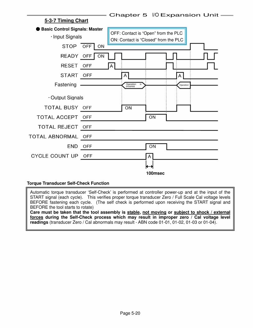
Chapter 5 I/O Expansion Unit
Page 5-20
5-3-7 Timing Chart ●●●● Basic Control Signals: Master
100msec
Torque Transducer Self-Check Function
OFF: Contact is “Open” from the PLC
ON: Contact is “Closed” from the PLC ・ Input Signals
・ Output Signals
Fastening Operation in progress
Operation
Automatic torque transducer ‘Self-Check’ is performed at controller power-up and at the input of the START signal (each cycle). This verifies proper torque transducer Zero / Full Scale Cal voltage levels BEFORE fastening each cycle. (The self check is performed upon receiving the START signal and BEFORE the tool starts to rotate) Care must be taken that the tool assembly is stable, not moving or subject to shock / external forces during the Self-Check process which may result in improper zero / Cal voltage level readings (transducer Zero / Cal abnormals may result - ABN code 01-01, 01-02, 01-03 or 01-04).
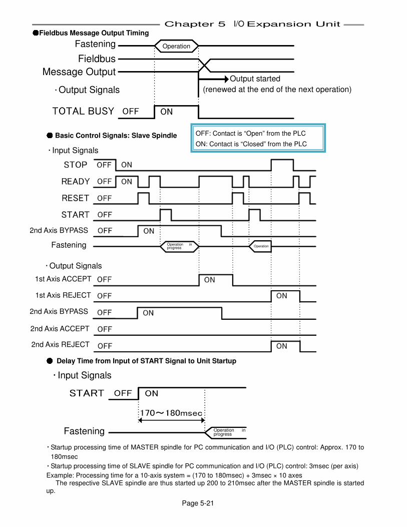
Chapter 5 I/O Expansion Unit
Page 5-21
●●●●Fieldbus Message Output Timing
●●●● Basic Control Signals: Slave Spindle
●●●● Delay Time from Input of START Signal to Unit Startup
・ Startup processing time of MASTER spindle for PC communication and I/O (PLC) control: Approx. 170 to
180msec ・ Startup processing time of SLAVE spindle for PC communication and I/O (PLC) control: 3msec (per axis)
Example: Processing time for a 10-axis system = (170 to 180msec) + 3msec × 10 axes The respective SLAVE spindle are thus started up 200 to 210msec after the MASTER spindle is started
up.
Operation
Operation Operation in progress
・ Output Signals
・ Input Signals
Fastening
OFF: Contact is “Open” from the PLC
ON: Contact is “Closed” from the PLC
Fieldbus
Message Output
Fastening
・ Output Signals
Output started
(renewed at the end of the next operation)
2nd Axis BYPASS
1st Axis ACCEPT
1st Axis REJECT
2nd Axis BYPASS
2nd Axis ACCEPT
2nd Axis REJECT
・ Input Signals
Fastening Operation in progress
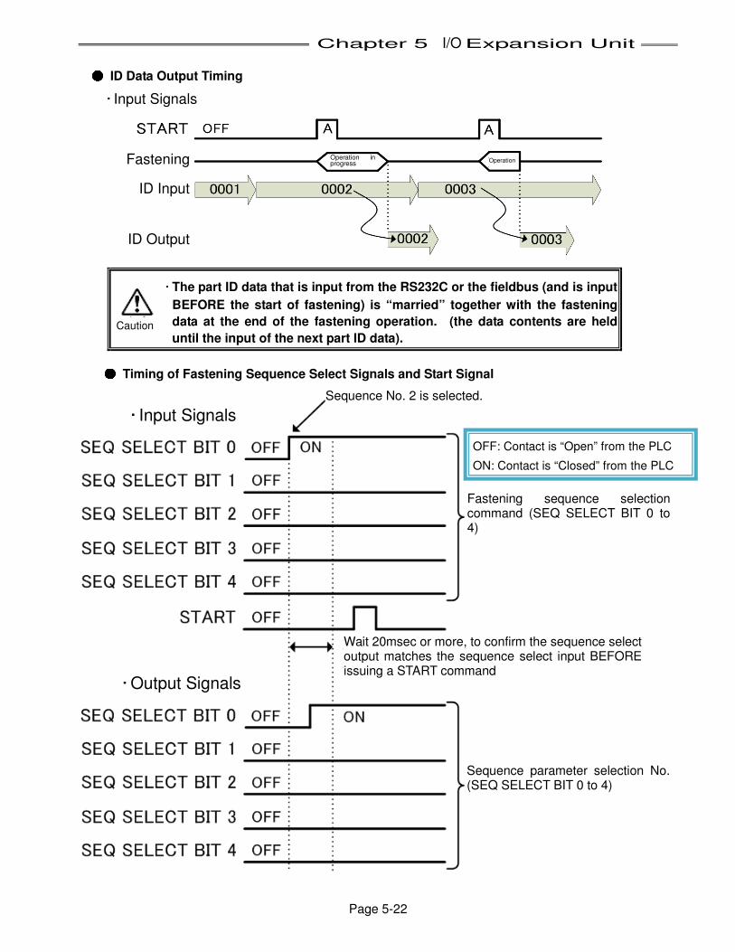
Chapter 5 I/O Expansion Unit
Page 5-22
●●●● ID Data Output Timing
・・・・ The part ID data that is input from the RS232C or the fieldbus (and is input
BEFORE the start of fastening) is “married” together with the fastening
data at the end of the fastening operation. (the data contents are held
until the input of the next part ID data).
●●●● Timing of Fastening Sequence Select Signals and Start Signal
・ Input Signals
・ Output Signals
・ Input Signals
Fastening
ID Input
ID Output
Operation in progress Operation
Caution
Sequence No. 2 is selected.
OFF: Contact is “Open” from the PLC
ON: Contact is “Closed” from the PLC
Fastening sequence selection command (SEQ SELECT BIT 0 to 4)
Wait 20msec or more, to confirm the sequence select output matches the sequence select input BEFORE issuing a START command
Sequence parameter selection No. (SEQ SELECT BIT 0 to 4)
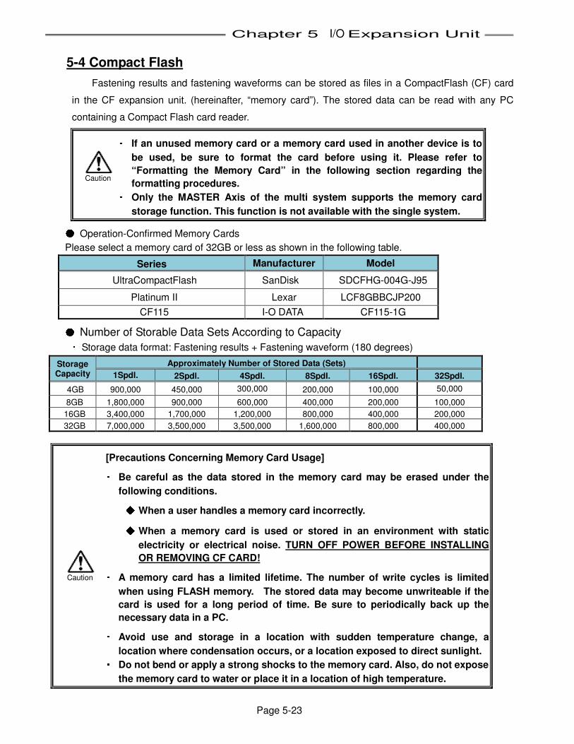
Chapter 5 I/O Expansion Unit
Page 5-23
5-4 Compact Flash
Fastening results and fastening waveforms can be stored as files in a CompactFlash (CF) card
in the CF expansion unit. (hereinafter, “memory card”). The stored data can be read with any PC
containing a Compact Flash card reader. ・・・・ If an unused memory card or a memory card used in another device is to
be used, be sure to format the card before using it. Please refer to
“Formatting the Memory Card” in the following section regarding the
formatting procedures. ・・・・ Only the MASTER Axis of the multi system supports the memory card
storage function. This function is not available with the single system. ● Operation-Confirmed Memory Cards
Please select a memory card of 32GB or less as shown in the following table.
Series Manufacturer Model
UltraCompactFlash SanDisk SDCFHG-004G-J95
Platinum II Lexar LCF8GBBCJP200
CF115 I-O DATA CF115-1G ● Number of Storable Data Sets According to Capacity ・ Storage data format: Fastening results + Fastening waveform (180 degrees)
Storage Capacity
Approximately Number of Stored Data (Sets)
1Spdl. 2Spdl. 4Spdl. 8Spdl. 16Spdl. 32Spdl.
4GB 900,000 450,000 300,000 200,000 100,000 50,000
8GB 1,800,000 900,000 600,000 400,000 200,000 100,000
16GB 3,400,000 1,700,000 1,200,000 800,000 400,000 200,000
32GB 7,000,000 3,500,000 3,500,000 1,600,000 800,000 400,000
[Precautions Concerning Memory Card Usage] ・・・・ Be careful as the data stored in the memory card may be erased under the
following conditions. ◆◆◆◆ When a user handles a memory card incorrectly. ◆◆◆◆ When a memory card is used or stored in an environment with static
electricity or electrical noise. TURN OFF POWER BEFORE INSTALLING
OR REMOVING CF CARD! ・・・・ A memory card has a limited lifetime. The number of write cycles is limited
when using FLASH memory. The stored data may become unwriteable if the
card is used for a long period of time. Be sure to periodically back up the
necessary data in a PC. ・・・・ Avoid use and storage in a location with sudden temperature change, a
location where condensation occurs, or a location exposed to direct sunlight. ・・・・ Do not bend or apply a strong shocks to the memory card. Also, do not expose
the memory card to water or place it in a location of high temperature.
Caution
Caution
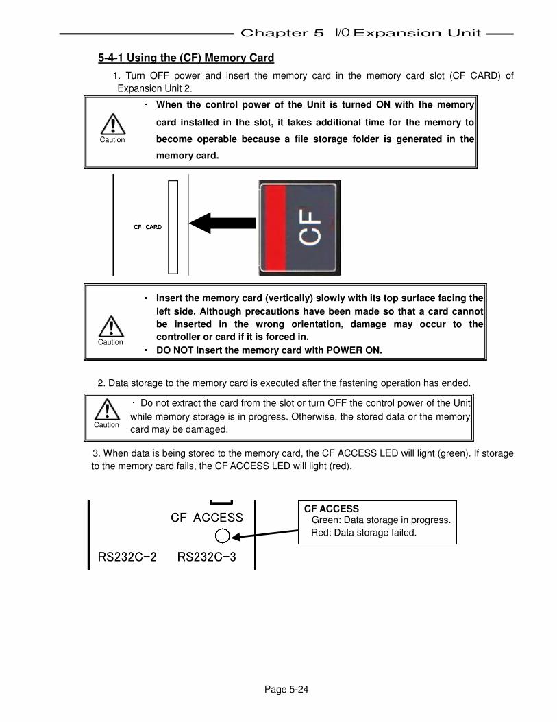
Chapter 5 I/O Expansion Unit
Page 5-24
5-4-1 Using the (CF) Memory Card
1. Turn OFF power and insert the memory card in the memory card slot (CF CARD) of
Expansion Unit 2. ・・・・ When the control power of the Unit is turned ON with the memory
card installed in the slot, it takes additional time for the memory to
become operable because a file storage folder is generated in the
memory card.
・・・・ Insert the memory card (vertically) slowly with its top surface facing the
left side. Although precautions have been made so that a card cannot
be inserted in the wrong orientation, damage may occur to the
controller or card if it is forced in. ・・・・ DO NOT insert the memory card with POWER ON.
2. Data storage to the memory card is executed after the fastening operation has ended. ・ Do not extract the card from the slot or turn OFF the control power of the Unit
while memory storage is in progress. Otherwise, the stored data or the memory
card may be damaged. 3. When data is being stored to the memory card, the CF ACCESS LED will light (green). If storage
to the memory card fails, the CF ACCESS LED will light (red).
CF ACCESS Green: Data storage in progress.
Red: Data storage failed.
Caution
Caution Caution
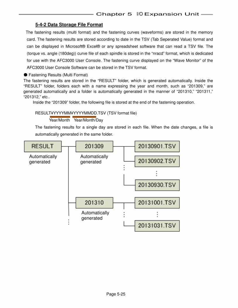
Chapter 5 I/O Expansion Unit
Page 5-25
5-4-2 Data Storage File Format
The fastening results (multi format) and the fastening curves (waveforms) are stored in the memory
card. The fastening results are stored according to date in the TSV (Tab Seperated Value) format and
can be displayed in Microsoft® Excel® or any spreadsheet software that can read a TSV file. The
(torque vs. angle (180deg)) curve file of each spindle is stored in the “nracd” format, which is dedicated
for use with the AFC3000 User Console. The fastening curve displayed on the “Wave Monitor” of the
AFC3000 User Console Software can be stored in the TSV format. ● Fastening Results (Multi Format)
The fastening results are stored in the “RESULT” folder, which is generated automatically. Inside the
“RESULT” folder, folders each with a name expressing the year and month, such as “201309,” are
generated automatically and a folder is automatically generated in the manner of “201310,” “201311,”
“201312,” etc..
Inside the “201309” folder, the following file is stored at the end of the fastening operation.
RESULT¥YYYYMM¥YYYYMMDD.TSV (TSV format file) Year/Month Year/Month/Day
The fastening results for a single day are stored in each file. When the date changes, a file is
automatically generated in the same folder.
Automatically generated
Automatically generated
Automatically generated
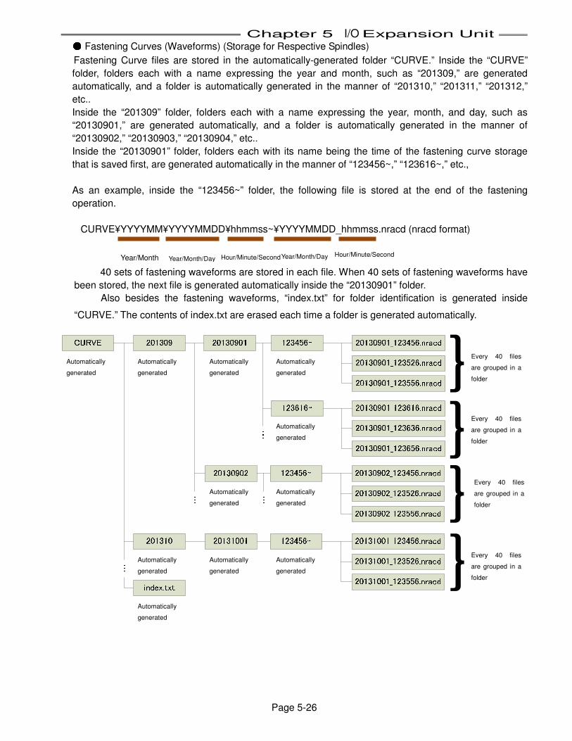
Chapter 5 I/O Expansion Unit
Page 5-26
● Fastening Curves (Waveforms) (Storage for Respective Spindles)
Fastening Curve files are stored in the automatically-generated folder “CURVE.” Inside the “CURVE”
folder, folders each with a name expressing the year and month, such as “201309,” are generated
automatically, and a folder is automatically generated in the manner of “201310,” “201311,” “201312,”
etc..
Inside the “201309” folder, folders each with a name expressing the year, month, and day, such as
“20130901,” are generated automatically, and a folder is automatically generated in the manner of
“20130902,” “20130903,” “20130904,” etc..
Inside the “20130901” folder, folders each with its name being the time of the fastening curve storage
that is saved first, are generated automatically in the manner of “123456~,” “123616~,” etc.,
As an example, inside the “123456~” folder, the following file is stored at the end of the fastening
operation.
CURVE¥YYYYMM¥YYYYMMDD¥hhmmss~¥YYYYMMDD_hhmmss.nracd (nracd format)
Year/Month 40 sets of fastening waveforms are stored in each file. When 40 sets of fastening waveforms have
been stored, the next file is generated automatically inside the “20130901” folder.
Also besides the fastening waveforms, “index.txt” for folder identification is generated inside
“CURVE.” The contents of index.txt are erased each time a folder is generated automatically.
・・・・・・ ・・・
・・・
Automatically
generated Automatically
generated Automatically
generated Automatically
generated Automatically
generated Automatically
generated Automatically
generated Automatically
generated Automatically
generated Automatically
generated Automatically
generated
Every 40 files
are grouped in a
folder Every 40 files
are grouped in a
folder Every 40 files
are grouped in a
folder Every 40 files
are grouped in a
folder
Year/Month/Day Hour/Minute/Second Year/Month/Day Hour/Minute/Second
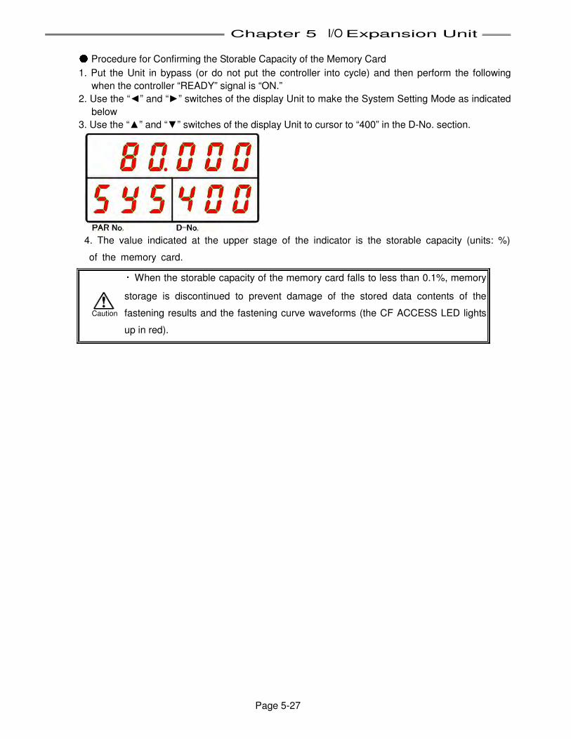
Chapter 5 I/O Expansion Unit
Page 5-27
● Procedure for Confirming the Storable Capacity of the Memory Card
1. Put the Unit in bypass (or do not put the controller into cycle) and then perform the following
when the controller “READY” signal is “ON.”
2. Use the “◄” and “►” switches of the display Unit to make the System Setting Mode as indicated
below
3. Use the “▲” and “▼” switches of the display Unit to cursor to “400” in the D-No. section.
4. The value indicated at the upper stage of the indicator is the storable capacity (units: %)
of the memory card. ・ When the storable capacity of the memory card falls to less than 0.1%, memory
storage is discontinued to prevent damage of the stored data contents of the
fastening results and the fastening curve waveforms (the CF ACCESS LED lights
up in red).
Caution
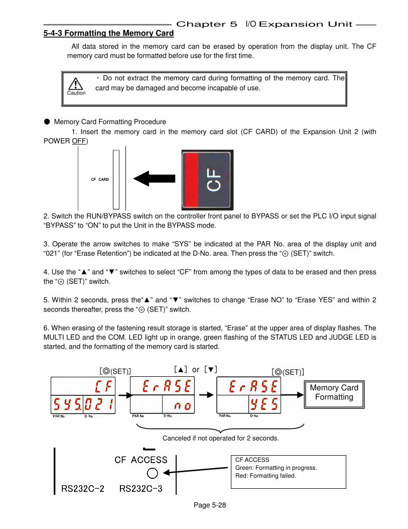
Chapter 5 I/O Expansion Unit
Page 5-28
5-4-3 Formatting the Memory Card
All data stored in the memory card can be erased by operation from the display unit. The CF
memory card must be formatted before use for the first time. ・ Do not extract the memory card during formatting of the memory card. The
card may be damaged and become incapable of use. ● Memory Card Formatting Procedure
1. Insert the memory card in the memory card slot (CF CARD) of the Expansion Unit 2 (with
POWER OFF)
2. Switch the RUN/BYPASS switch on the controller front panel to BYPASS or set the PLC I/O input signal
“BYPASS” to “ON” to put the Unit in the BYPASS mode.
3. Operate the arrow switches to make “SYS” be indicated at the PAR No. area of the display unit and
“021” (for “Erase Retention”) be indicated at the D-No. area. Then press the “⊚ (SET)” switch.
4. Use the “▲” and “▼” switches to select “CF” from among the types of data to be erased and then press
the “⊚ (SET)” switch.
5. Within 2 seconds, press the“▲” and “▼” switches to change “Erase NO” to “Erase YES” and within 2
seconds thereafter, press the “⊚ (SET)” switch.
6. When erasing of the fastening result storage is started, “Erase” at the upper area of display flashes. The
MULTI LED and the COM. LED light up in orange, green flashing of the STATUS LED and JUDGE LED is
started, and the formatting of the memory card is started.
CF ACCESS
Green: Formatting in progress.
Red: Formatting failed. Canceled if not operated for 2 seconds. Memory Card
Formatting
Caution
[◎(SET)] [▲] or [▼] [◎(SET)]
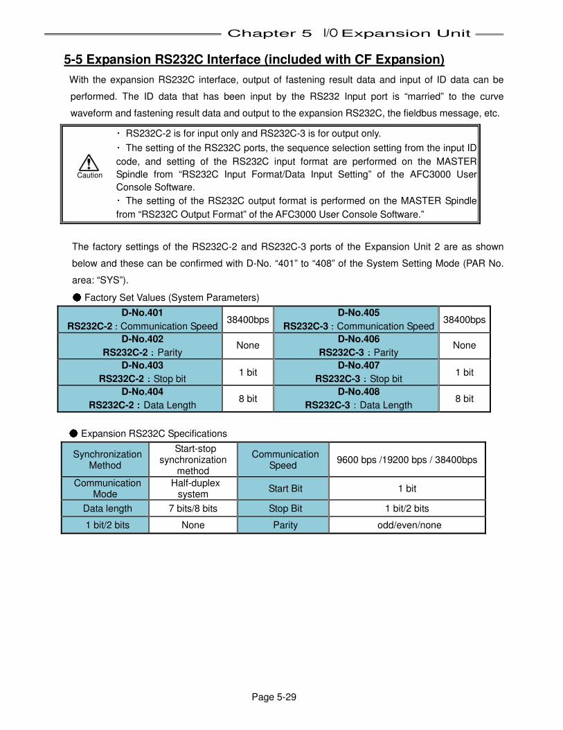
Chapter 5 I/O Expansion Unit
Page 5-29
5-5 Expansion RS232C Interface (included with CF Expansion)
With the expansion RS232C interface, output of fastening result data and input of ID data can be
performed. The ID data that has been input by the RS232 Input port is “married” to the curve
waveform and fastening result data and output to the expansion RS232C, the fieldbus message, etc. ・ RS232C-2 is for input only and RS232C-3 is for output only. ・ The setting of the RS232C ports, the sequence selection setting from the input ID
code, and setting of the RS232C input format are performed on the MASTER
Spindle from “RS232C Input Format/Data Input Setting” of the AFC3000 User
Console Software. ・ The setting of the RS232C output format is performed on the MASTER Spindle
from “RS232C Output Format” of the AFC3000 User Console Software.”
The factory settings of the RS232C-2 and RS232C-3 ports of the Expansion Unit 2 are as shown
below and these can be confirmed with D-No. “401” to “408” of the System Setting Mode (PAR No.
area: “SYS”). ● Factory Set Values (System Parameters)
D-No.401
RS232C-2::::Communication Speed 38400bps
D-No.405
RS232C-3::::Communication Speed 38400bps
D-No.402
RS232C-2::::Parity None
D-No.406
RS232C-3::::Parity None
D-No.403
RS232C-2::::Stop bit 1 bit
D-No.407
RS232C-3::::Stop bit 1 bit
D-No.404
RS232C-2::::Data Length 8 bit
D-No.408
RS232C-3::::Data Length 8 bit ● Expansion RS232C Specifications
Synchronization Method
Start-stop synchronization
method
Communication Speed
9600 bps /19200 bps / 38400bps
Communication Mode
Half-duplex system
Start Bit 1 bit
Data length 7 bits/8 bits Stop Bit 1 bit/2 bits
1 bit/2 bits None Parity odd/even/none
Caution
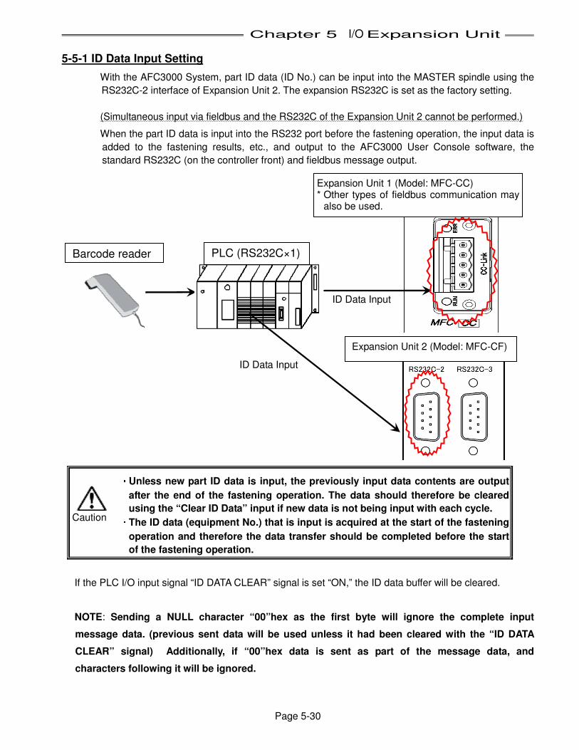
Chapter 5 I/O Expansion Unit
Page 5-30
5-5-1 ID Data Input Setting
With the AFC3000 System, part ID data (ID No.) can be input into the MASTER spindle using the
RS232C-2 interface of Expansion Unit 2. The expansion RS232C is set as the factory setting.
(Simultaneous input via fieldbus and the RS232C of the Expansion Unit 2 cannot be performed.)
When the part ID data is input into the RS232 port before the fastening operation, the input data is
added to the fastening results, etc., and output to the AFC3000 User Console software, the
standard RS232C (on the controller front) and fieldbus message output.
・・・・ Unless new part ID data is input, the previously input data contents are output
after the end of the fastening operation. The data should therefore be cleared
using the “Clear ID Data” input if new data is not being input with each cycle. ・・・・ The ID data (equipment No.) that is input is acquired at the start of the fastening
operation and therefore the data transfer should be completed before the start
of the fastening operation.
If the PLC I/O input signal “ID DATA CLEAR” signal is set “ON,” the ID data buffer will be cleared.
NOTE: Sending a NULL character “00”hex as the first byte will ignore the complete input
message data. (previous sent data will be used unless it had been cleared with the “ID DATA
CLEAR” signal) Additionally, if “00”hex data is sent as part of the message data, and
characters following it will be ignored.
Barcode reader
ID Data Input
Expansion Unit 2 (Model: MFC-CF)
PLC (RS232C×1)
Expansion Unit 1 (Model: MFC-CC) * Other types of fieldbus communication may
also be used.
ID Data Input
Caution
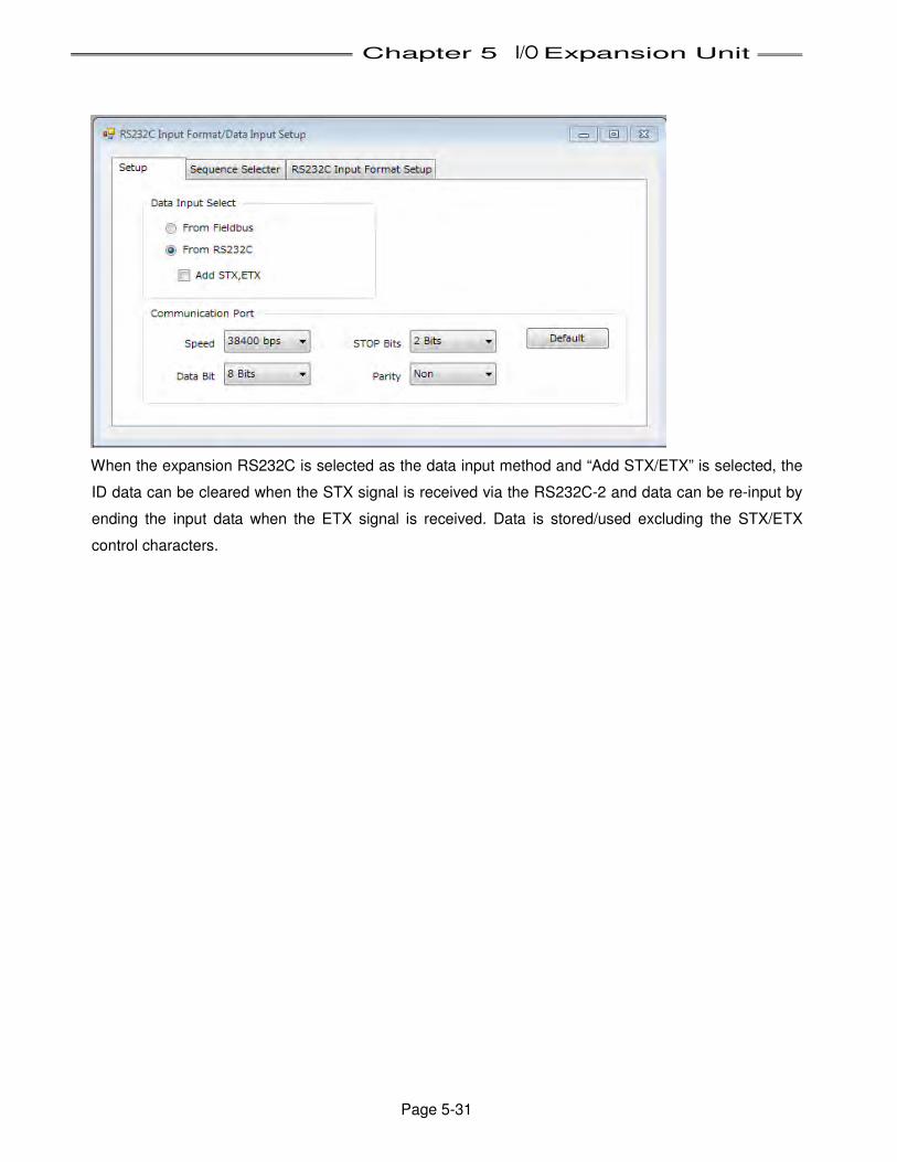
Chapter 5 I/O Expansion Unit
Page 5-31
When the expansion RS232C is selected as the data input method and “Add STX/ETX” is selected, the
ID data can be cleared when the STX signal is received via the RS232C-2 and data can be re-input by
ending the input data when the ETX signal is received. Data is stored/used excluding the STX/ETX
control characters.
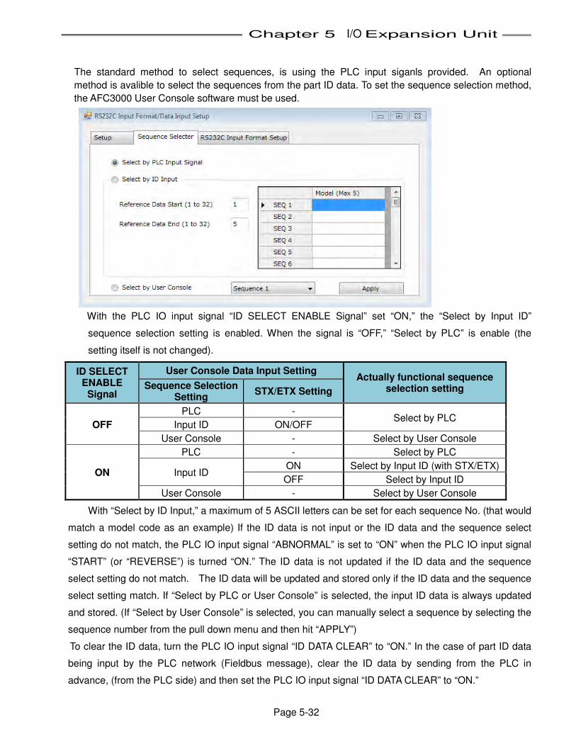
Chapter 5 I/O Expansion Unit
Page 5-32
The standard method to select sequences, is using the PLC input siganls provided. An optional
method is avalible to select the sequences from the part ID data. To set the sequence selection method,
the AFC3000 User Console software must be used.
With the PLC IO input signal “ID SELECT ENABLE Signal” set “ON,” the “Select by Input ID”
sequence selection setting is enabled. When the signal is “OFF,” “Select by PLC” is enable (the
setting itself is not changed).
ID SELECT ENABLE
Signal
User Console Data Input Setting Actually functional sequence
selection setting Sequence Selection Setting
STX/ETX Setting
OFF
PLC - Select by PLC
Input ID ON/OFF
User Console - Select by User Console
ON
PLC - Select by PLC
Input ID ON Select by Input ID (with STX/ETX)
OFF Select by Input ID
User Console - Select by User Console
With “Select by ID Input,” a maximum of 5 ASCII letters can be set for each sequence No. (that would
match a model code as an example) If the ID data is not input or the ID data and the sequence select
setting do not match, the PLC IO input signal “ABNORMAL” is set to “ON” when the PLC IO input signal
“START” (or “REVERSE”) is turned “ON.” The ID data is not updated if the ID data and the sequence
select setting do not match. The ID data will be updated and stored only if the ID data and the sequence
select setting match. If “Select by PLC or User Console” is selected, the input ID data is always updated
and stored. (If “Select by User Console” is selected, you can manually select a sequence by selecting the
sequence number from the pull down menu and then hit “APPLY”)
To clear the ID data, turn the PLC IO input signal “ID DATA CLEAR” to “ON.” In the case of part ID data
being input by the PLC network (Fieldbus message), clear the ID data by sending from the PLC in
advance, (from the PLC side) and then set the PLC IO input signal “ID DATA CLEAR” to “ON.”

Chapter 6 Power up and Initial Checks
PAGE 6-1
Chapter 6: Power Up and Initial Checks
6
Chapter 6 Power up and Initial Checks
PAGE 6-2
6-1 Power Activation・・・・Operational Test
WARNING
DO NOT operate the system WITHOUT all safety guards and/or devices in place and operational. Follow Lockout/Tagout and other safety precautions when performing maintenance or connecting / disconnecting cabling, wiring, and equipment. There is a possibility of electrical shock from this equipment if used improperly.
6-1-1 Before Powering On
• Verify MFC Controller Rotary/DIP switch settings (Section 4-12) Verify that the (2) rotary switches visible on the front of each controller are set to indicate the appropriate spindle number. Verify that SW1 and SW2 loacted on the front and bottom of the controller are set to indicate the appropriate function and options.
• Check connection between tool and controller (Section 4-5) Verify that the homerun and extension cables (resolver, motor and transducer) connecting the tool to the MFC controller are secure. Ensure that each numbered set of cables are connected to the identically numbered tool and MFC controller. If the application requires the tool mounting fixture to move, visually inspect all components to ensure that there is proper clearance and that cables have sufficient length. If movement would create any excessive stress on a cable or create any potential for damage to the system, then make appropriate adjustments. Confirm the bend radius of any tool cable(s) are more than 6” (min) and follow cabling guidelines.
WARNING: DO NOT make motor connections with the power on. Turn off all controller power before attempting to connect or disconnect any motor cables or system damage may occur.
• Check MFC Controller I/O cable wiring (Section 4-6) Connections with external control equipment are done between MFC Controller I/O connectors and/or (Fieldbus) Expansion unit I/O connectors. Verify that the I/O interface wiring is connected to the corresponding PLC terminals.
• Check the Input Voltages (Section 2-1, 4-4) Verify that the Input Power Connectors (Main and 24VDC Control) are properly wired and that the voltage to be applied is within the specified range. Verify that the 24VDC and 0VDC common wires are properly connected. Damage may occur if wired improperly.
AAAAAAAAllllllllwwwwwwwwaaaaaaaayyyyyyyyssssssss vvvvvvvveeeeeeeerrrrrrrr iiiiiiii ffffffffyyyyyyyy tttttttthhhhhhhheeeeeeee iiiiiiii tttttttteeeeeeeemmmmmmmmssssssss aaaaaaaabbbbbbbboooooooovvvvvvvveeeeeeee bbbbbbbbeeeeeeeeffffffffoooooooorrrrrrrreeeeeeee ppppppppoooooooowwwwwwwweeeeeeeerrrrrrrr iiiiiiiinnnnnnnngggggggg oooooooonnnnnnnn
• Power Voltage Re-Checks Re-check the input power voltage after turning the power on to make sure the voltage does not drop due to loading. Check again for loading when the spindle has started and the torque is at its maximum level for the fastening cycle (maximum power consumption time).
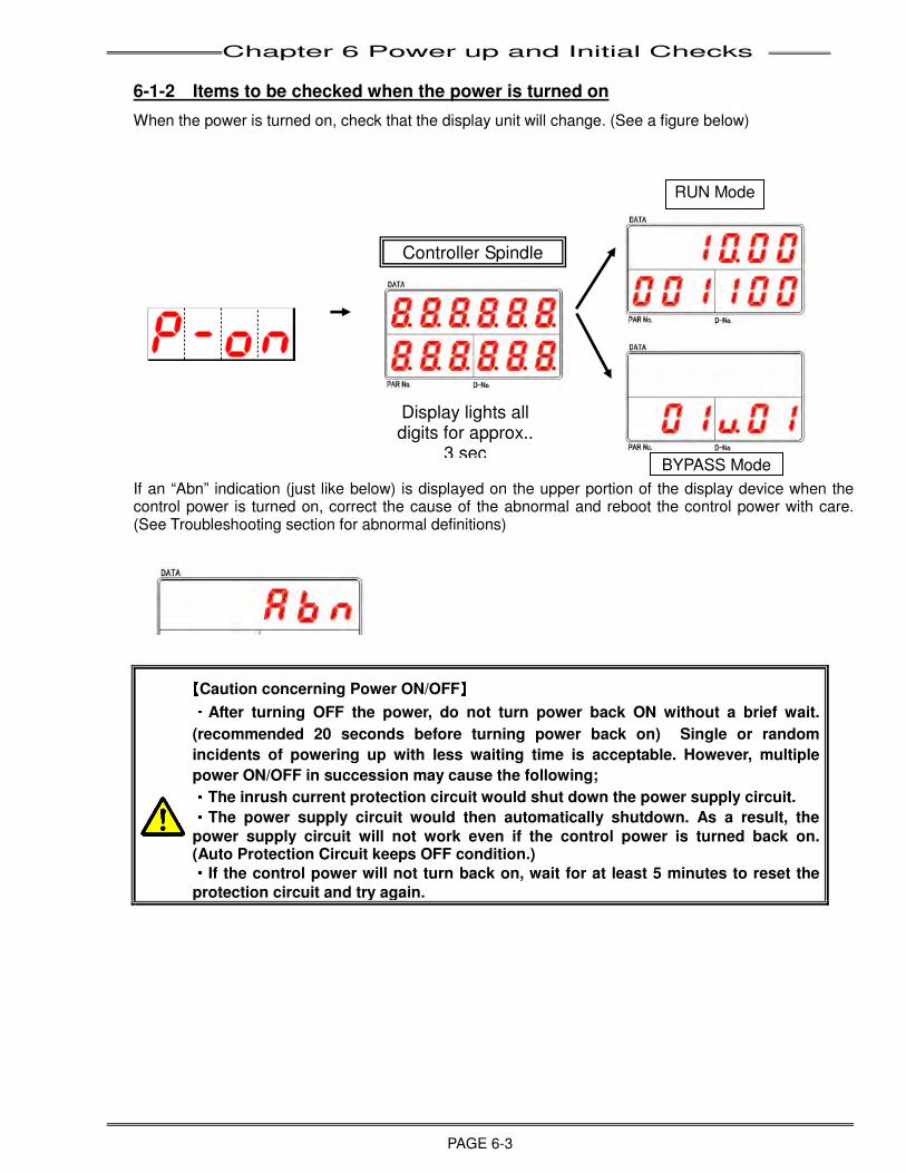
Chapter 6 Power up and Initial Checks
PAGE 6-3
6-1-2 Items to be checked when the power is turned on
When the power is turned on, check that the display unit will change. (See a figure below)
If an “Abn” indication (just like below) is displayed on the upper portion of the display device when the control power is turned on, correct the cause of the abnormal and reboot the control power with care. (See Troubleshooting section for abnormal definitions)
【【【【Caution concerning Power ON/OFF】】】】 ・・・・After turning OFF the power, do not turn power back ON without a brief wait.
(recommended 20 seconds before turning power back on) Single or random
incidents of powering up with less waiting time is acceptable. However, multiple
power ON/OFF in succession may cause the following; ・・・・The inrush current protection circuit would shut down the power supply circuit. ・・・・The power supply circuit would then automatically shutdown. As a result, the
power supply circuit will not work even if the control power is turned back on. (Auto Protection Circuit keeps OFF condition.) ・・・・If the control power will not turn back on, wait for at least 5 minutes to reset the
protection circuit and try again.
RUN Mode
Display lights all digits for approx..
3 sec
Controller Spindle
BYPASS Mode

Chapter 6 Power up and Initial Checks
PAGE 6-4
6-1-3 Initial Data Setting
After completion of the System verification/power on procedure in Section 6-1-1, the system is ready for the input of data required for the fastening operation. Chapters 7 and 8 give details on the types of information required and the procedure for entering data into the System. The system will not run until this data is correctly set-up.
Programming should be performed using the FEC Inc. “AFC3000 Userconsole” software to simplify the programming operation and to provide a means of creating a back-up file of the Set-up.
NOTE: Most AFC3000 systems are delivered with application-specific fastening data already setup (if provided by customer). This set-up data is considered preliminary and should be adjusted according to actual process / part runs for optimal performance.
After the system is setup with the appropriate data, verify all MFC Controller RUN/BYPASS switches are set to RUN. Also, check that the STOP signal from the external control equipment (PLC, selector switch, etc.) is set ON (System will NOT run unless STOP signal is ON). Perform the following procedure by attaching the Display and Programming Unit:
1) Zero Value Check
Press the RESET button on the Display Unit and check that the value displayed on the unit is at or near zero and that the NG LED (red) is not on.
2) CAL. Point Check
Press the CAL button on the Display Unit and check that the NG LED (red) is not on.
Before performing the following tests, make sure there are no obstructions in the tool area prior to activating a spindle or other moveable component.
3) Manual REVERSE Check
Set the RUN/BYPASS switch on each MFC Controller as follows: 1. Verify MFC Controller #1 is set to RUN. 2. Set all other MFC Controllers to the BYPASS position.
Press the manual REV button on front of the Keyboard-display Unit. Verify that spindle #1 is turning in the appropriate direction (opposite the preset direction) and that all other spindles are motionless. (See NOTE below.)
Next, switch MFC Controller #1 to the BYPASS position. Switch MFC Controller #2 to RUN and verify spindle #2 reverse operation (reference previous Step).
Repeat this procedure for each MFC Controller/spindle. It is important to complete this step for each MFC Controller/spindle prior to performing the next step.
After all MFC Controllers are verified individually, ensure that each of the BYPASS switches are set to the RUN position.
NOTE: : If any MFC Controller fails to activate the appropriate spindle, correct the situation before
continuing to the next controller. First, check the nutrunner (tool) cables going to the MFC Controller to verify correct connections to the appropriate components.
4) Manual START Check
Press the START button on the display unit and verify that all connected tools run in the correct direction until the pre-programmed time elapses, creating a reject. If setup for a multi spindle system this can only be performed on the Master’s display unit.
Press the RESET button on the Main operator panel to clear the REJECT light and LED outputs from the MFC Controllers.
5) External Instruction Operation Check Verify that the equipment will operate with an instruction from the exterior control equipment
(PLC, selector switch, etc.). Use the PLC to perform all of the functions (START, CAL, etc.) that were manually activated earlier in this Section.

Chapter 7 Fastening Instructions
PAGE 7-1
Chapter 7: Fastening Instructions
7
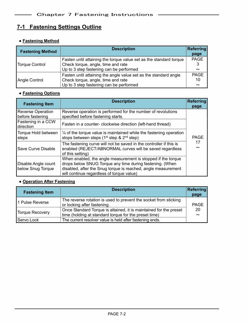
Chapter 7 Fastening Instructions
PAGE 7-2
7-1 Fastening Settings Outline
● Fastening Method
Fastening Method Description Referring page
Torque Control Fasten until attaining the torque value set as the standard torque Check torque, angle, time and rate Up to 3 step fastening can be performed
PAGE 3 ~
Angle Control Fasten until attaining the angle value set as the standard angle Check torque, angle, time and rate Up to 3 step fastening can be performed
PAGE 10 ~
● Fastening Options
Fastening Item Description Referring page
Reverse Operation before fastening
Reverse operation is performed for the number of revolutions specified before fastening starts.
PAGE 17 ~
Fastening in a CCW direction Fasten in a counter- clockwise direction (left-hand thread)
Torque Hold between steps
¼ of the torque value is maintained while the fastening operation stops between steps (1st step & 2nd step)
Save Curve Disable The fastening curve will not be saved in the controller if this is enabled (REJECT/ABNORMAL curves will be saved regardless of this setting)
Disable Angle count below Snug Torque
When enabled, the angle measurement is stopped if the torque drops below SNUG Torque any time during fastening. (When disabled, after the Snug torque is reached, angle measurement will continue regardless of torque value)
● Operation After Fastening
Fastening Item Description Referring page
1 Pulse Reverse The reverse rotation is used to prevent the socket from sticking or locking after fastening. PAGE
20 ~ Torque Recovery Once Standard Torque is attained, it is maintained for the preset
time (holding at standard torque for the preset time) Servo Lock The current resolver value is held after fastening ends.
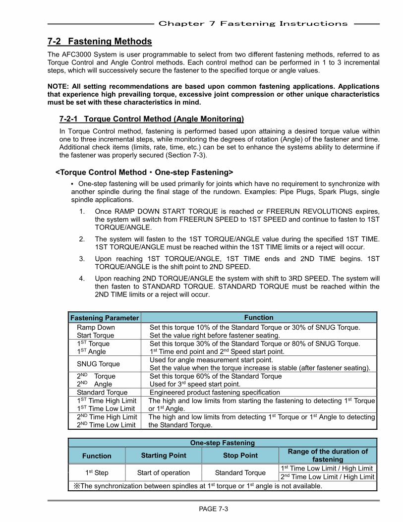
Chapter 7 Fastening Instructions
PAGE 7-3
7-2 Fastening Methods The AFC3000 System is user programmable to select from two different fastening methods, referred to as Torque Control and Angle Control methods. Each control method can be performed in 1 to 3 incremental steps, which will successively secure the fastener to the specified torque or angle values. NOTE: All setting recommendations are based upon common fastening applications. Applications that experience high prevailing torque, excessive joint compression or other unique characteristics must be set with these characteristics in mind.
7-2-1 Torque Control Method (Angle Monitoring) In Torque Control method, fastening is performed based upon attaining a desired torque value within one to three incremental steps, while monitoring the degrees of rotation (Angle) of the fastener and time. Additional check items (limits, rate, time, etc.) can be set to enhance the systems ability to determine if the fastener was properly secured (Section 7-3).
<Torque Control Method・One-step Fastening>
P One-step fastening will be used primarily for joints which have no requirement to synchronize with another spindle during the final stage of the rundown. Examples: Pipe Plugs, Spark Plugs, single spindle applications.
1. Once RAMP DOWN START TORQUE is reached or FREERUN REVOLUTIONS expires, the system will switch from FREERUN SPEED to 1ST SPEED and continue to fasten to 1ST TORQUE/ANGLE.
2. The system will fasten to the 1ST TORQUE/ANGLE value during the specified 1ST TIME. 1ST TORQUE/ANGLE must be reached within the 1ST TIME limits or a reject will occur.
3. Upon reaching 1ST TORQUE/ANGLE, 1ST TIME ends and 2ND TIME begins. 1ST TORQUE/ANGLE is the shift point to 2ND SPEED.
4. Upon reaching 2ND TORQUE/ANGLE the system with shift to 3RD SPEED. The system will then fasten to STANDARD TORQUE. STANDARD TORQUE must be reached within the 2ND TIME limits or a reject will occur.
Fastening Parameter Function
Ramp Down Start Torque
Set this torque 10% of the Standard Torque or 30% of SNUG Torque. Set the value right before fastener seating.
1ST Torque 1ST Angle
Set this torque 30% of the Standard Torque or 80% of SNUG Torque. 1st Time end point and 2nd Speed start point.
SNUG Torque Used for angle measurement start point. Set the value when the torque increase is stable (after fastener seating).
2ND Torque 2ND Angle
Set this torque 60% of the Standard Torque Used for 3rd speed start point.
Standard Torque Engineered product fastening specification 1ST Time High Limit 1ST Time Low Limit
The high and low limits from starting the fastening to detecting 1st Torque or 1st Angle.
2ND Time High Limit 2ND Time Low Limit
The high and low limits from detecting 1st Torque or 1st Angle to detecting the Standard Torque.
One-step Fastening
Function Starting Point Stop Point Range of the duration of fastening
1st Step Start of operation Standard Torque 1st Time Low Limit / High Limit 2nd Time Low Limit / High Limit
※The synchronization between spindles at 1st torque or 1st angle is not available.
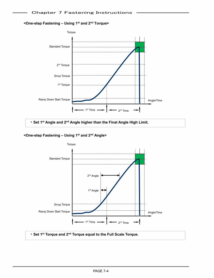
Chapter 7 Fastening Instructions
PAGE 7-4
<One-step Fastening – Using 1st and 2nd Torque>
<One-step Fastening – Using 1st and 2nd Angle>
・Set 1st Torque and 2nd Torque equal to the Full Scale Torque.
・Set 1st Angle and 2nd Angle higher than the Final Angle High Limit.
Standard Torque
Ramp Down Start Torque
1st Torque
2nd Torque
Snug Torque
1st Time 2nd Time
Torque
Angle/Time
Standard Torque
Ramp Down Start Torque
1st Angle
2nd Angle
Snug Torque
1st Time 2nd Time
Torque
Angle/Time
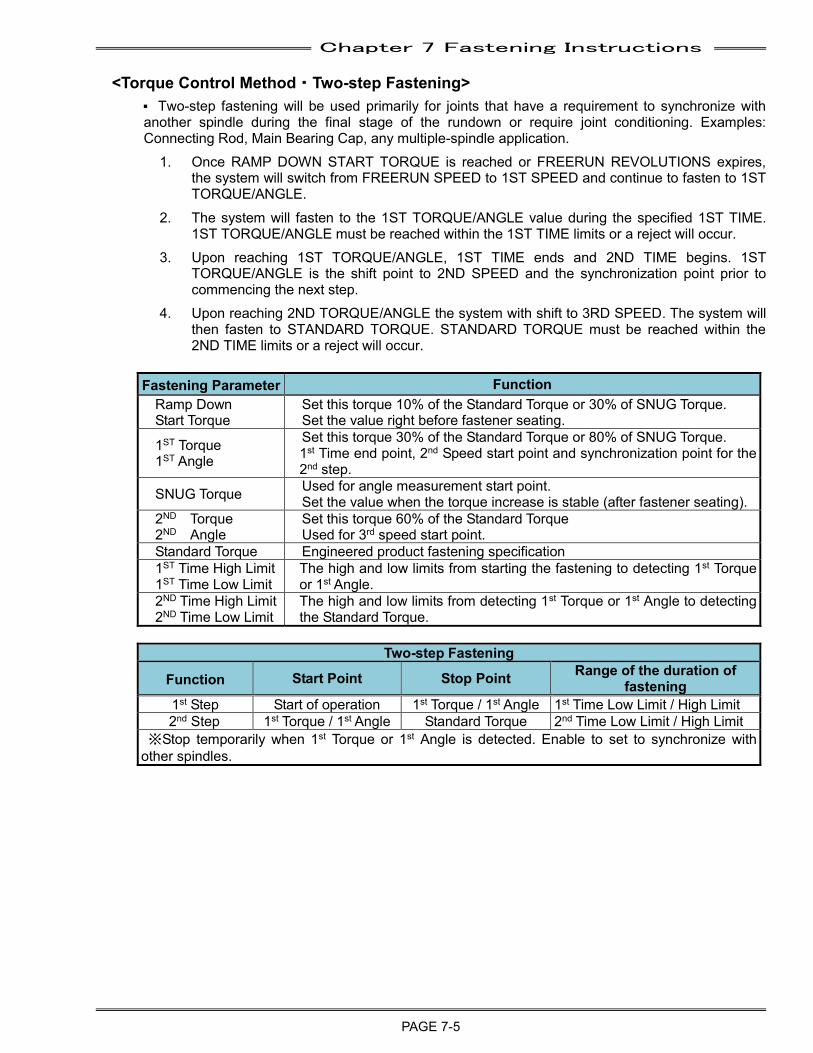
Chapter 7 Fastening Instructions
PAGE 7-5
<Torque Control Method・Two-step Fastening>
P Two-step fastening will be used primarily for joints that have a requirement to synchronize with another spindle during the final stage of the rundown or require joint conditioning. Examples: Connecting Rod, Main Bearing Cap, any multiple-spindle application.
1. Once RAMP DOWN START TORQUE is reached or FREERUN REVOLUTIONS expires, the system will switch from FREERUN SPEED to 1ST SPEED and continue to fasten to 1ST TORQUE/ANGLE.
2. The system will fasten to the 1ST TORQUE/ANGLE value during the specified 1ST TIME. 1ST TORQUE/ANGLE must be reached within the 1ST TIME limits or a reject will occur.
3. Upon reaching 1ST TORQUE/ANGLE, 1ST TIME ends and 2ND TIME begins. 1ST TORQUE/ANGLE is the shift point to 2ND SPEED and the synchronization point prior to commencing the next step.
4. Upon reaching 2ND TORQUE/ANGLE the system with shift to 3RD SPEED. The system will then fasten to STANDARD TORQUE. STANDARD TORQUE must be reached within the 2ND TIME limits or a reject will occur.
Fastening Parameter Function
Ramp Down Start Torque
Set this torque 10% of the Standard Torque or 30% of SNUG Torque. Set the value right before fastener seating.
1ST Torque 1ST Angle
Set this torque 30% of the Standard Torque or 80% of SNUG Torque. 1st Time end point, 2nd Speed start point and synchronization point for the 2nd step.
SNUG Torque Used for angle measurement start point. Set the value when the torque increase is stable (after fastener seating).
2ND Torque 2ND Angle
Set this torque 60% of the Standard Torque Used for 3rd speed start point.
Standard Torque Engineered product fastening specification 1ST Time High Limit 1ST Time Low Limit
The high and low limits from starting the fastening to detecting 1st Torque or 1st Angle.
2ND Time High Limit 2ND Time Low Limit
The high and low limits from detecting 1st Torque or 1st Angle to detecting the Standard Torque.
Two-step Fastening
Function Start Point Stop Point Range of the duration of fastening
1st Step Start of operation 1st Torque / 1st Angle 1st Time Low Limit / High Limit 2nd Step 1st Torque / 1st Angle Standard Torque 2nd Time Low Limit / High Limit
※Stop temporarily when 1st Torque or 1st Angle is detected. Enable to set to synchronize with other spindles.
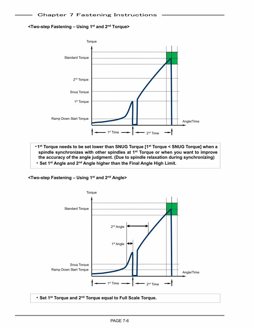
Chapter 7 Fastening Instructions
PAGE 7-6
Torque
Torque
<Two-step Fastening – Using 1st and 2nd Torque>
<Two-step Fastening – Using 1st and 2nd Angle>
・Set 1st Torque and 2nd Torque equal to Full Scale Torque.
・1st Torque needs to be set lower than SNUG Torque [1st Torque < SNUG Torque] when a spindle synchronizes with other spindles at 1st Torque or when you want to improve the accuracy of the angle judgment. (Due to spindle relaxation during synchronizing)
・Set 1st Angle and 2nd Angle higher than the Final Angle High Limit.
Angle/Time
Snug Torque
1st Time 2nd Time
Standard Torque
Ramp Down Start Torque
1st Torque
2nd Torque
Angle/Time
Snug Torque
1st Time 2nd Time
Standard Torque
Ramp Down Start Torque
1st Angle
2nd Angle
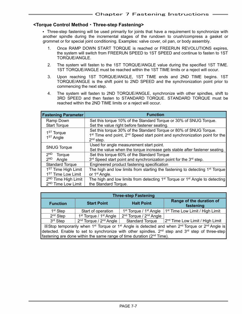
Chapter 7 Fastening Instructions
PAGE 7-7
<Torque Control Method・Three-step Fastening>
P Three-step fastening will be used primarily for joints that have a requirement to synchronize with another spindle during the incremental stages of the rundown to crush/compress a gasket or grommet or for special joint conditioning. Examples: valve cover, oil pan, or body assembly.
1. Once RAMP DOWN START TORQUE is reached or FREERUN REVOLUTIONS expires, the system will switch from FREERUN SPEED to 1ST SPEED and continue to fasten to 1ST TORQUE/ANGLE.
2. The system will fasten to the 1ST TORQUE/ANGLE value during the specified 1ST TIME. 1ST TORQUE/ANGLE must be reached within the 1ST TIME limits or a reject will occur.
3. Upon reaching 1ST TORQUE/ANGLE, 1ST TIME ends and 2ND TIME begins. 1ST TORQUE/ANGLE is the shift point to 2ND SPEED and the synchronization point prior to commencing the next step.
4. The system will fasten to 2ND TORQUE/ANGLE, synchronize with other spindles, shift to 3RD SPEED and then fasten to STANDARD TORQUE. STANDARD TORQUE must be reached within the 2ND TIME limits or a reject will occur.
Fastening Parameter Function
Ramp Down Start Torque
Set this torque 10% of the Standard Torque or 30% of SNUG Torque. Set the value right before fastener seating.
1ST Torque 1ST Angle
Set this torque 30% of the Standard Torque or 80% of SNUG Torque. 1st Time end point, 2nd Speed start point and synchronization point for the 2nd step.
SNUG Torque Used for angle measurement start point. Set the value when the torque increase gets stable after fastener seating.
2ND Torque 2ND Angle
Set this torque 60% of the Standard Torque 3rd Speed start point and synchronization point for the 3rd step.
Standard Torque Engineered product fastening specification 1ST Time High Limit 1ST Time Low Limit
The high and low limits from starting the fastening to detecting 1st Torque or 1st Angle.
2ND Time High Limit 2ND Time Low Limit
The high and low limits from detecting 1st Torque or 1st Angle to detecting the Standard Torque.
Three-step Fastening
Function Start Point Halt Point Range of the duration of fastening
1st Step Start of operation 1st Torque / 1st Angle 1st Time Low Limit / High Limit 2nd Step 1st Torque / 1st Angle 2nd Torque / 2nd Angle
2nd Time Low Limit / High Limit 3rd Step 2nd Torque / 2nd Angle Standard Torque ※Stop temporarily when 1st Torque or 1st Angle is detected and when 2nd Torque or 2nd Angle is
detected. Enable to set to synchronize with other spindles. 2nd step and 3rd step of three-step fastening are done within the same range of time duration (2nd Time).
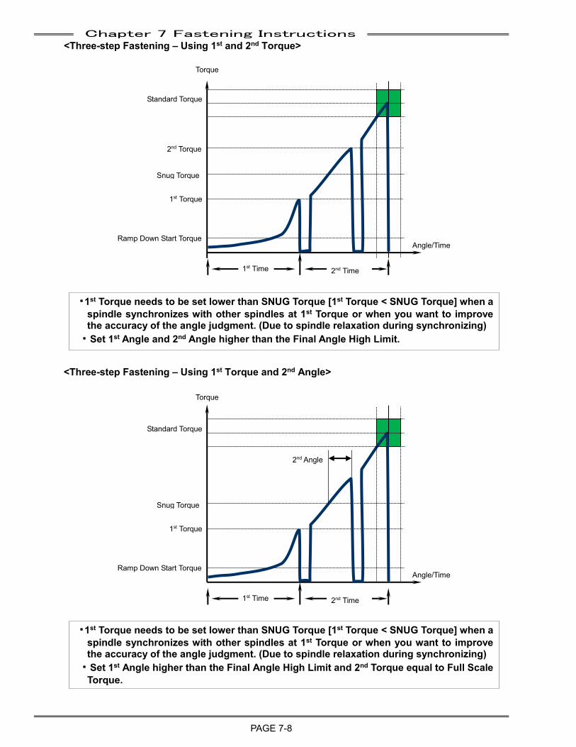
Chapter 7 Fastening Instructions
PAGE 7-8
<Three-step Fastening – Using 1st and 2nd Torque>
<Three-step Fastening – Using 1st Torque and 2nd Angle>
・1st Torque needs to be set lower than SNUG Torque [1st Torque < SNUG Torque] when a spindle synchronizes with other spindles at 1st Torque or when you want to improve the accuracy of the angle judgment. (Due to spindle relaxation during synchronizing)
・Set 1st Angle higher than the Final Angle High Limit and 2nd Torque equal to Full Scale Torque.
・1st Torque needs to be set lower than SNUG Torque [1st Torque < SNUG Torque] when a spindle synchronizes with other spindles at 1st Torque or when you want to improve the accuracy of the angle judgment. (Due to spindle relaxation during synchronizing)
・Set 1st Angle and 2nd Angle higher than the Final Angle High Limit.
Torque
Angle/Time
Snug Torque
1st Time 2nd Time
Standard Torque
Ramp Down Start Torque
1st Torque
2nd Torque
Torque
Angle/Time
Snug Torque
1st Time 2nd Time
Standard Torque
Ramp Down Start Torque
1st Torque
2nd Angle
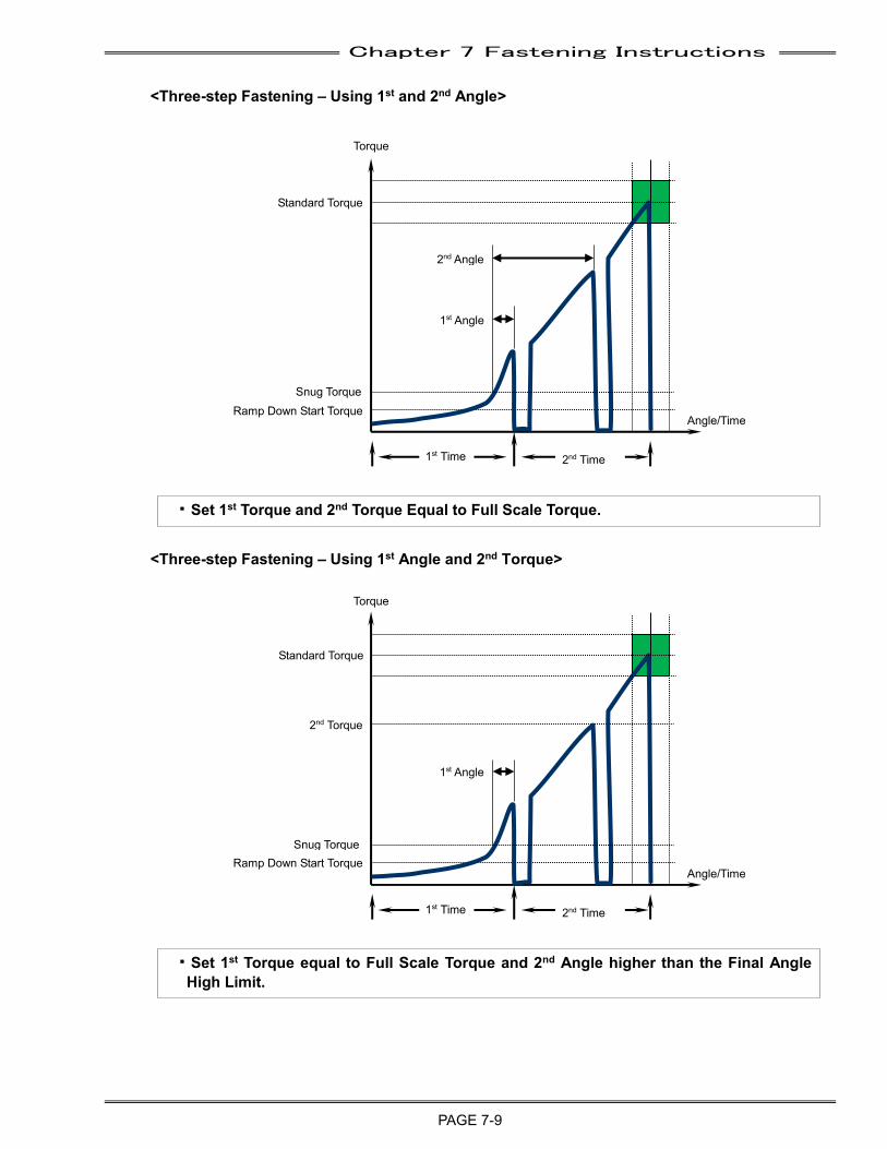
Chapter 7 Fastening Instructions
PAGE 7-9
<Three-step Fastening – Using 1st and 2nd Angle>
<Three-step Fastening – Using 1st Angle and 2nd Torque>
・Set 1st Torque equal to Full Scale Torque and 2nd Angle higher than the Final Angle High Limit.
・Set 1st Torque and 2nd Torque Equal to Full Scale Torque.
Torque
Angle/Time
1st Time 2nd Time
Standard Torque
Ramp Down Start Torque
1st Angle
2nd Torque
Torque
Angle/Time
1st Time 2nd Time
Standard Torque
Ramp Down Start Torque
1st Angle
2nd Angle
Snug Torque
Snug Torque
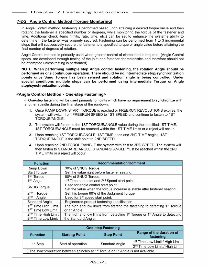
Chapter 7 Fastening Instructions
PAGE 7-10
7-2-2 Angle Control Method (Torque Monitoring) In Angle Control method, fastening is performed based upon attaining a desired torque value and then rotating the fastener a specified number of degrees, while monitoring the torque of the fastener and time. Additional check items (limits, rate, time, etc.) can be set to enhance the systems ability to determine if the fastener was properly secured. Fastening can be performed from 1 to 3 incremental steps that will successively secure the fastener to a specified torque or angle value before attaining the final number of degrees of rotation. Angle Control method is primarily used when greater control of clamp load is required. (Angle Control specs. are developed through testing of the joint and fastener characteristics and therefore should not be attempted unless testing is performed) NOTE: When performing multiple step Angle control fastening, the rotation Angle should be performed as one continuous operation. There should be no intermediate stop/synchronization points once Snug Torque has been sensed and rotation angle is being controlled. Under special conditions multiple steps can be performed using intermediate Torque or Angle stop/synchronization points.
<Angle Control Method・One-step Fastening>
P One-step fastening will be used primarily for joints which have no requirement to synchronize with another spindle during the final stage of the rundown.
1. Once RAMP DOWN START TORQUE is reached or FREERUN REVOLUTIONS expires, the system will switch from FREERUN SPEED to 1ST SPEED and continue to fasten to 1ST TORQUE/ANGLE.
2. The system will fasten to the 1ST TORQUE/ANGLE value during the specified 1ST TIME. 1ST TORQUE/ANGLE must be reached within the 1ST TIME limits or a reject will occur.
3. Upon reaching 1ST TORQUE/ANGLE, 1ST TIME ends and 2ND TIME begins. 1ST TORQUE/ANGLE is the shift point to 2ND SPEED.
4. Upon reaching 2ND TORQUE/ANGLE the system with shift to 3RD SPEED. The system will then fasten to STANDARD ANGLE. STANDARD ANGLE must be reached within the 2ND TIME limits or a reject will occur.
Function Recommendation/Comment
Ramp Down Start Torque
30% of SNUG Torque. Set the value right before fastener seating.
1ST Torque 1ST Angle
80% of SNUG Torque. 1st Time end point and 2nd Speed start point.
SNUG Torque Used for angle control start point. Set the value when the torque increase is stable after fastener seating.
2ND Torque 2ND Angle
Set this torque 60% of the Judgment Torque Used for 3rd speed start point.
Standard Angle Engineered product fastening specification 1ST Time High Limit 1ST Time Low Limit
The high and low limits from starting the fastening to detecting 1st Torque or 1st Angle.
2ND Time High Limit 2ND Time Low Limit
The high and low limits from detecting 1st Torque or 1st Angle to detecting the Standard Angle.
One-step Fastening
Function Starting Point Stop Point Range of the duration of fastening
1st Step Start of operation Standard Angle 1st Time Low Limit / High Limit 2nd Time Low Limit / High Limit
※The synchronization between spindles at 1st Torque or 1st Angle is not available.
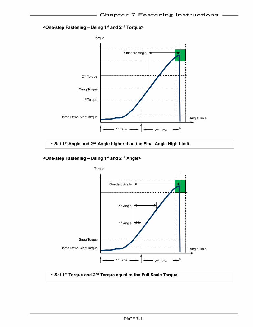
Chapter 7 Fastening Instructions
PAGE 7-11
<One-step Fastening – Using 1st and 2nd Torque>
<One-step Fastening – Using 1st and 2nd Angle>
・Set 1st Torque and 2nd Torque equal to the Full Scale Torque.
・Set 1st Angle and 2nd Angle higher than the Final Angle High Limit.
Standard Angle
Ramp Down Start Torque
1st Torque
2nd Torque
Snug Torque
1st Time 2nd Time
Torque
Angle/Time
Standard Angle
Ramp Down Start Torque
1st Angle
2nd Angle
Snug Torque
1st Time 2nd Time
Torque
Angle/Time
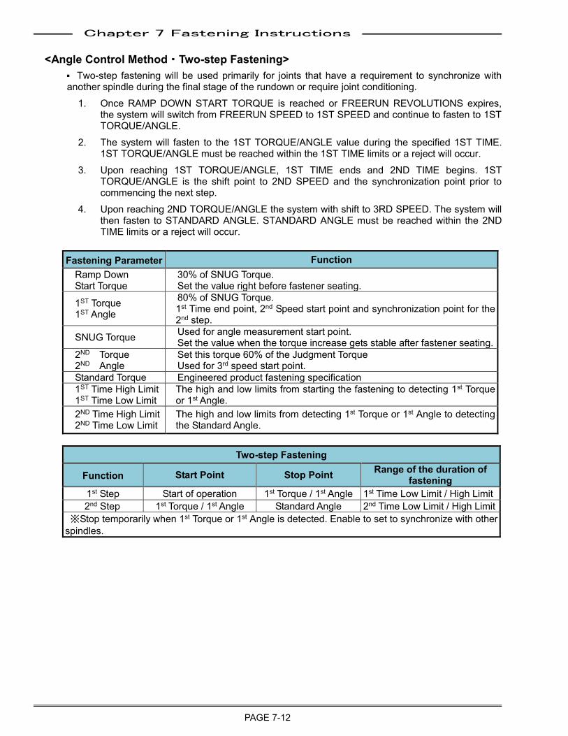
Chapter 7 Fastening Instructions
PAGE 7-12
<Angle Control Method・Two-step Fastening> P Two-step fastening will be used primarily for joints that have a requirement to synchronize with another spindle during the final stage of the rundown or require joint conditioning.
1. Once RAMP DOWN START TORQUE is reached or FREERUN REVOLUTIONS expires, the system will switch from FREERUN SPEED to 1ST SPEED and continue to fasten to 1ST TORQUE/ANGLE.
2. The system will fasten to the 1ST TORQUE/ANGLE value during the specified 1ST TIME. 1ST TORQUE/ANGLE must be reached within the 1ST TIME limits or a reject will occur.
3. Upon reaching 1ST TORQUE/ANGLE, 1ST TIME ends and 2ND TIME begins. 1ST TORQUE/ANGLE is the shift point to 2ND SPEED and the synchronization point prior to commencing the next step.
4. Upon reaching 2ND TORQUE/ANGLE the system with shift to 3RD SPEED. The system will then fasten to STANDARD ANGLE. STANDARD ANGLE must be reached within the 2ND TIME limits or a reject will occur.
Fastening Parameter Function
Ramp Down Start Torque
30% of SNUG Torque. Set the value right before fastener seating.
1ST Torque 1ST Angle
80% of SNUG Torque. 1st Time end point, 2nd Speed start point and synchronization point for the 2nd step.
SNUG Torque Used for angle measurement start point. Set the value when the torque increase gets stable after fastener seating.
2ND Torque 2ND Angle
Set this torque 60% of the Judgment Torque Used for 3rd speed start point.
Standard Torque Engineered product fastening specification 1ST Time High Limit 1ST Time Low Limit
The high and low limits from starting the fastening to detecting 1st Torque or 1st Angle.
2ND Time High Limit 2ND Time Low Limit
The high and low limits from detecting 1st Torque or 1st Angle to detecting the Standard Angle.
Two-step Fastening
Function Start Point Stop Point Range of the duration of fastening
1st Step Start of operation 1st Torque / 1st Angle 1st Time Low Limit / High Limit 2nd Step 1st Torque / 1st Angle Standard Angle 2nd Time Low Limit / High Limit
※Stop temporarily when 1st Torque or 1st Angle is detected. Enable to set to synchronize with other spindles.
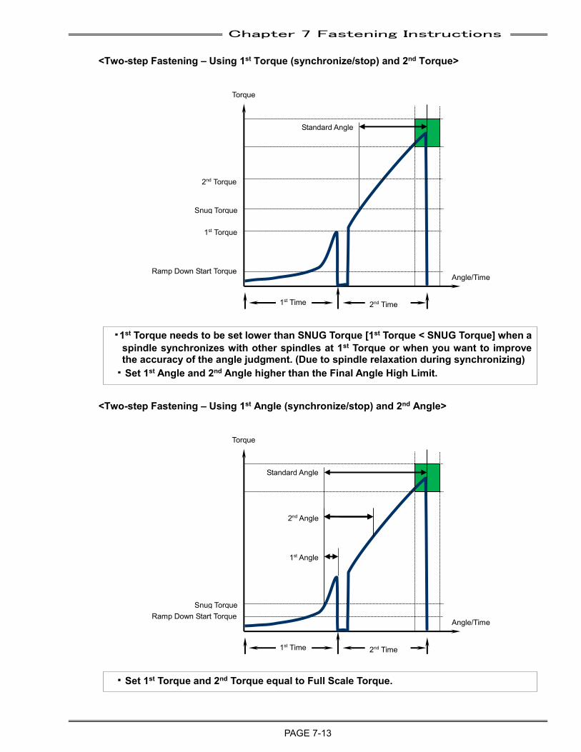
Chapter 7 Fastening Instructions
PAGE 7-13
Torque
Torque
<Two-step Fastening – Using 1st Torque (synchronize/stop) and 2nd Torque>
<Two-step Fastening – Using 1st Angle (synchronize/stop) and 2nd Angle>
・Set 1st Torque and 2nd Torque equal to Full Scale Torque.
・1st Torque needs to be set lower than SNUG Torque [1st Torque < SNUG Torque] when a spindle synchronizes with other spindles at 1st Torque or when you want to improve the accuracy of the angle judgment. (Due to spindle relaxation during synchronizing)
・Set 1st Angle and 2nd Angle higher than the Final Angle High Limit.
Angle/Time
Snug Torque
1st Time 2nd Time
Standard Angle
Ramp Down Start Torque
1st Torque
2nd Torque
Angle/Time
Snug Torque
1st Time 2nd Time
Standard Angle
Ramp Down Start Torque
1st Angle
2nd Angle
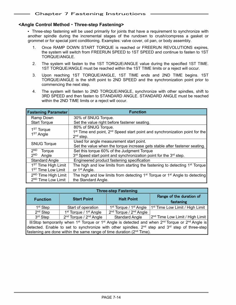
Chapter 7 Fastening Instructions
PAGE 7-14
<Angle Control Method・Three-step Fastening> P Three-step fastening will be used primarily for joints that have a requirement to synchronize with another spindle during the incremental stages of the rundown to crush/compress a gasket or grommet or for special joint conditioning. Examples: valve cover, oil pan, or body assembly.
1. Once RAMP DOWN START TORQUE is reached or FREERUN REVOLUTIONS expires, the system will switch from FREERUN SPEED to 1ST SPEED and continue to fasten to 1ST TORQUE/ANGLE.
2. The system will fasten to the 1ST TORQUE/ANGLE value during the specified 1ST TIME. 1ST TORQUE/ANGLE must be reached within the 1ST TIME limits or a reject will occur.
3. Upon reaching 1ST TORQUE/ANGLE, 1ST TIME ends and 2ND TIME begins. 1ST TORQUE/ANGLE is the shift point to 2ND SPEED and the synchronization point prior to commencing the next step.
4. The system will fasten to 2ND TORQUE/ANGLE, synchronize with other spindles, shift to 3RD SPEED and then fasten to STANDARD ANGLE. STANDARD ANGLE must be reached within the 2ND TIME limits or a reject will occur.
Fastening Parameter Function
Ramp Down Start Torque
30% of SNUG Torque. Set the value right before fastener seating.
1ST Torque 1ST Angle
80% of SNUG Torque. 1st Time end point, 2nd Speed start point and synchronization point for the 2nd step.
SNUG Torque Used for angle measurement start point. Set the value when the torque increase gets stable after fastener seating.
2ND Torque 2ND Angle
Set this torque 60% of the Judgment Torque 3rd Speed start point and synchronization point for the 3rd step.
Standard Angle Engineered product fastening specification 1ST Time High Limit 1ST Time Low Limit
The high and low limits from starting the fastening to detecting 1st Torque or 1st Angle.
2ND Time High Limit 2ND Time Low Limit
The high and low limits from detecting 1st Torque or 1st Angle to detecting the Standard Angle.
Three-step Fastening
Function Start Point Halt Point Range of the duration of
fastening
1st Step Start of operation 1st Torque / 1st Angle 1st Time Low Limit / High Limit 2nd Step 1st Torque / 1st Angle 2nd Torque / 2nd Angle
2nd Time Low Limit / High Limit 3rd Step 2nd Torque / 2nd Angle Standard Angle ※Stop temporarily when 1st Torque or 1st Angle is detected and when 2nd Torque or 2nd Angle is
detected. Enable to set to synchronize with other spindles. 2nd step and 3rd step of three-step fastening are done within the same range of time duration (2nd Time).
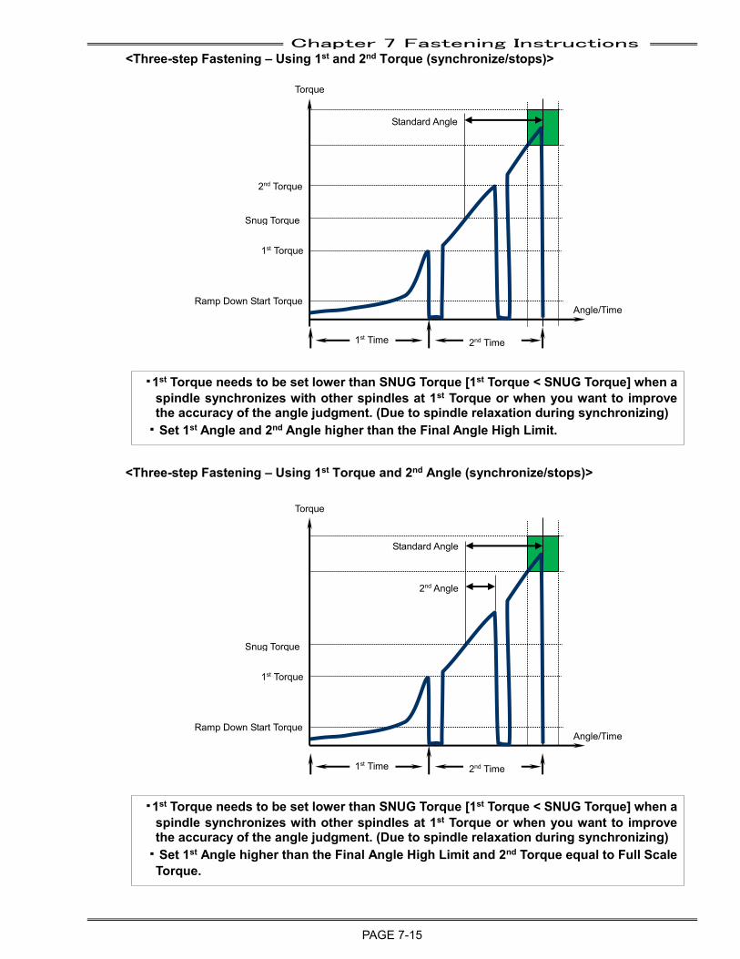
Chapter 7 Fastening Instructions
PAGE 7-15
<Three-step Fastening – Using 1st and 2nd Torque (synchronize/stops)>
<Three-step Fastening – Using 1st Torque and 2nd Angle (synchronize/stops)>
・1st Torque needs to be set lower than SNUG Torque [1st Torque < SNUG Torque] when a spindle synchronizes with other spindles at 1st Torque or when you want to improve the accuracy of the angle judgment. (Due to spindle relaxation during synchronizing)
・Set 1st Angle higher than the Final Angle High Limit and 2nd Torque equal to Full Scale Torque.
・1st Torque needs to be set lower than SNUG Torque [1st Torque < SNUG Torque] when a spindle synchronizes with other spindles at 1st Torque or when you want to improve the accuracy of the angle judgment. (Due to spindle relaxation during synchronizing)
・Set 1st Angle and 2nd Angle higher than the Final Angle High Limit.
Torque
Angle/Time
Snug Torque
1st Time 2nd Time
Standard Angle
Ramp Down Start Torque
1st Torque
2nd Torque
Torque
Angle/Time
Snug Torque
1st Time 2nd Time
Standard Angle
Ramp Down Start Torque
1st Torque
2nd Angle
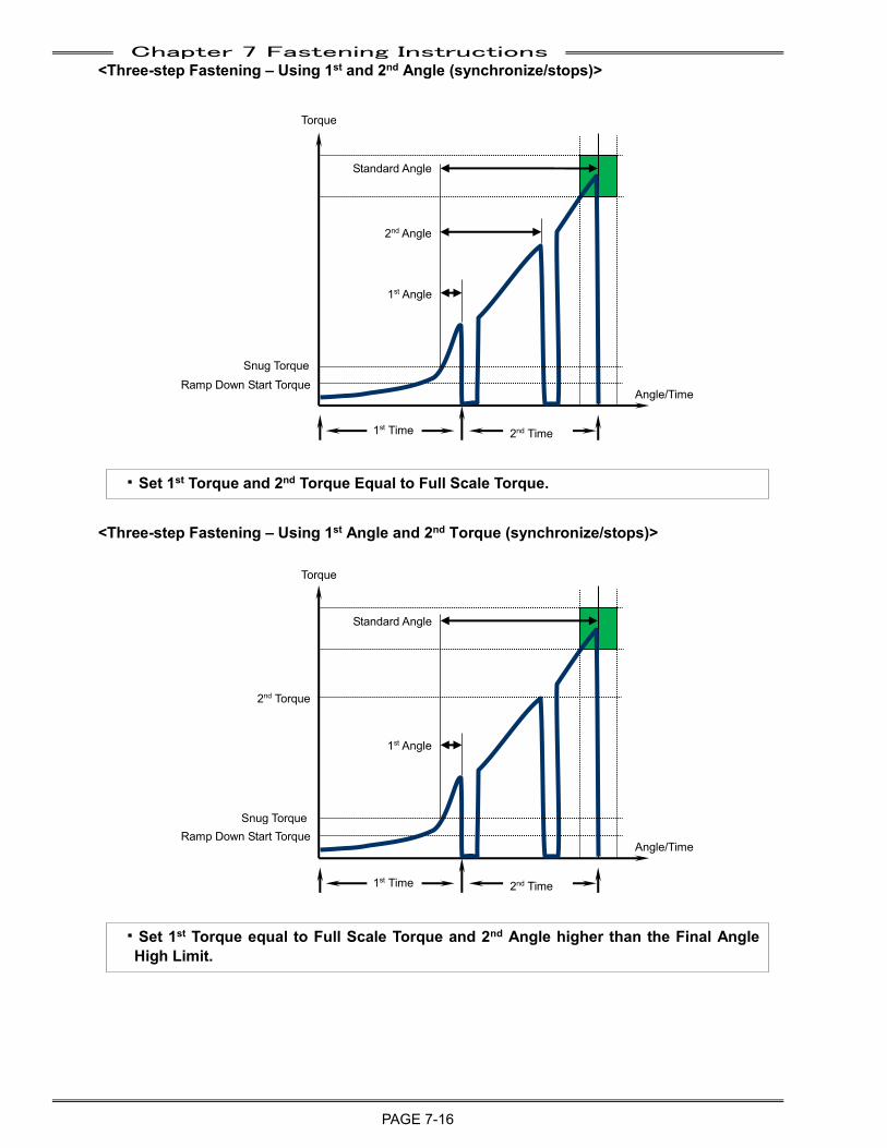
Chapter 7 Fastening Instructions
PAGE 7-16
<Three-step Fastening – Using 1st and 2nd Angle (synchronize/stops)>
<Three-step Fastening – Using 1st Angle and 2nd Torque (synchronize/stops)>
・Set 1st Torque equal to Full Scale Torque and 2nd Angle higher than the Final Angle High Limit.
・Set 1st Torque and 2nd Torque Equal to Full Scale Torque.
Torque
Angle/Time
1st Time 2nd Time
Standard Angle
Ramp Down Start Torque
1st Angle
2nd Torque
Torque
Angle/Time
1st Time 2nd Time
Standard Angle
Ramp Down Start Torque
1st Angle
2nd Angle
Snug Torque
Snug Torque
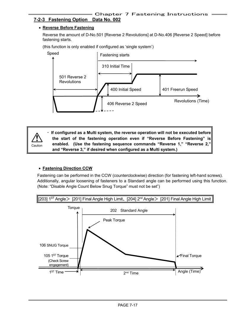
Chapter 7 Fastening Instructions
PAGE 7-17
7-2-3 Fastening Option Data No. 002
• Reverse Before Fastening
Reverse the amount of D-No.501 [Reverse 2 Revolutions] at D-No.406 [Reverse 2 Speed] before fastening starts. (this function is only enabled if configured as ‘single system’)
Revolutions (Time)
• Fastening Direction CCW Fastening can be performed in the CCW (counterclockwise) direction (for fastening left-hand screws). Additionally, angular loosening of fasteners to a Standard angle can be performed using this function. (Note: “Disable Angle Count Below Snug Torque” must not be set”) [203] 1ST Angle> [201] Final Angle High Limit、[204] 2nd Angle> [201] Final Angle High Limit
・ If configured as a Multi system, the reverse operation will not be executed before the start of the fastening operation even if “Reverse Before Fastening” is enabled. (Use the fastening sequence commands “Reverse 1,” “Reverse 2,” and “Reverse 3,” if desired when configured as a Multi system.)
202 Standard Angle
Peak Torque
106 SNUG Torque
105 1ST Torque Final Torque
(Check Screw engagement)
1ST Time 2nd Time Angle (Time)
Torque
Speed Fastening starts
501 Reverse 2 Revolutions
400 Initial Speed 401フリーラン
401 Freerun Speed
310 Initial Time
406 Reverse 2 Speed
Caution
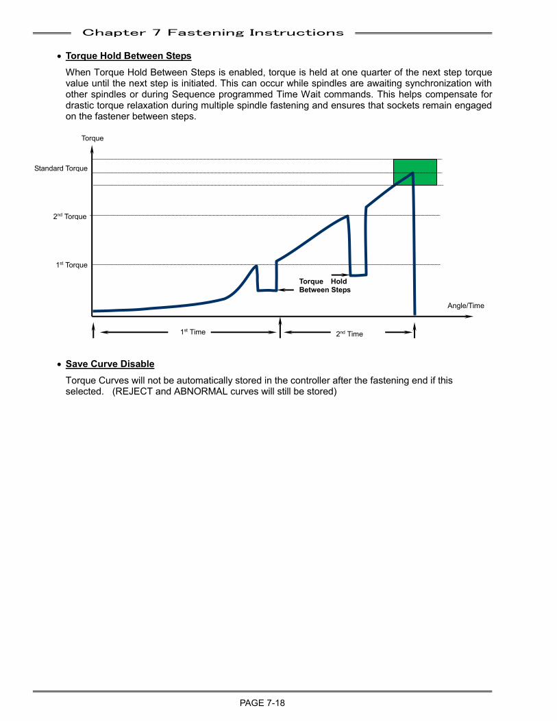
Chapter 7 Fastening Instructions
PAGE 7-18
• Torque Hold Between Steps
When Torque Hold Between Steps is enabled, torque is held at one quarter of the next step torque value until the next step is initiated. This can occur while spindles are awaiting synchronization with other spindles or during Sequence programmed Time Wait commands. This helps compensate for drastic torque relaxation during multiple spindle fastening and ensures that sockets remain engaged on the fastener between steps.
• Save Curve Disable
Torque Curves will not be automatically stored in the controller after the fastening end if this selected. (REJECT and ABNORMAL curves will still be stored)
Torque
Angle/Time
Standard Torque
1st Torque
2nd Torque
1st Time 2nd Time
Torque Hold Between Steps
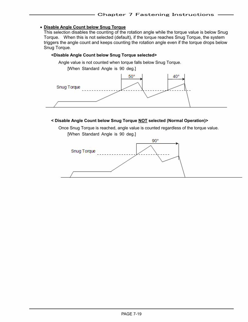
Chapter 7 Fastening Instructions
PAGE 7-19
• Disable Angle Count below Snug Torque This selection disables the counting of the rotation angle while the torque value is below Snug Torque. When this is not selected (default), if the torque reaches Snug Torque, the system triggers the angle count and keeps counting the rotation angle even if the torque drops below Snug Torque.
<Disable Angle Count below Snug Torque selected> Angle value is not counted when torque falls below Snug Torque.
[When Standard Angle is 90 deg.]
< Disable Angle Count below Snug Torque NOT selected (Normal Operation)> Once Snug Torque is reached, angle value is counted regardless of the torque value.
[When Standard Angle is 90 deg.]
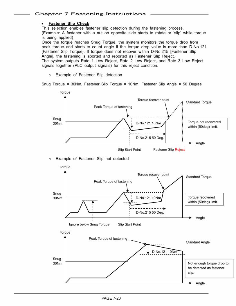
Chapter 7 Fastening Instructions
PAGE 7-20
• Fastener Slip Check This selection enables fastener slip detection during the fastening process. (Example: A fastener with a nut on opposite side starts to rotate or ‘slip’ while torque is being applied) Once the torque reaches Snug Torque, the system monitors the torque drop from peak torque and starts to count angle if the torque drop value is more than D-No.121[Fastener Slip Torque]. If torque does not recover within D-No.215 [Fastener Slip Angle], the fastening is aborted and reported as Fastener Slip Reject. The system outputs Rate 1 Low Reject, Rate 2 Low Reject, and Rate 3 Low Reject signals together (PLC output signals) for this reject condition.
o Example of Fastener Slip detection
Snug Torque = 30Nm, Fastener Slip Torque = 10Nm, Fastener Slip Angle = 50 Degree
o Example of Fastener Slip not detected
Torque
Snug 30Nm
Angle
D-No.121 10Nm
Slip Start Point
D-No.215 50 Deg.
Fastener Slip Reject
Standard Torque Peak Torque of fastening
Torque recover point
Torque
Snug 30Nm
Angle
D-No.121 10Nm
Slip Start Point
D-No.215 50 Deg.
Torque recovered within (50deg) limit.
Standard Torque Peak Torque of fastening
Torque recover point
Torque
Snug 30Nm
Angle
D-No.121 10Nm
Not enough torque drop to be detected as fastener slip.
Standard Angle Peak Torque of fastening
Ignore below Snug Torque
Torque not recovered within (50deg) limit.
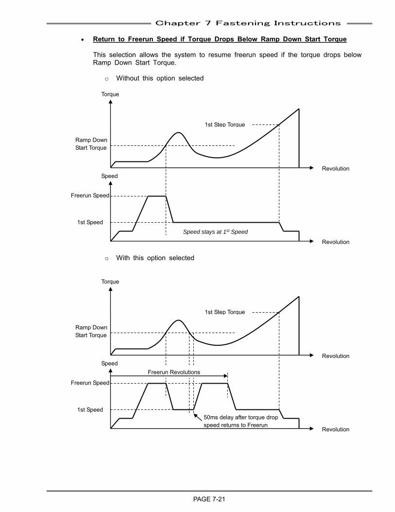
Chapter 7 Fastening Instructions
PAGE 7-21
• Return to Freerun Speed if Torque Drops Below Ramp Down Start Torque
This selection allows the system to resume freerun speed if the torque drops below Ramp Down Start Torque.
o Without this option selected
o With this option selected
Torque
Revolution Speed
Revolution
Ramp Down Start Torque
1st Step Torque
Freerun Speed
1st Speed
Torque
Revolution Speed
Revolution
Ramp Down Start Torque
1st Step Torque
Freerun Speed
1st Speed
Freerun Revolutions
50ms delay after torque drop speed returns to Freerun
Speed stays at 1st Speed
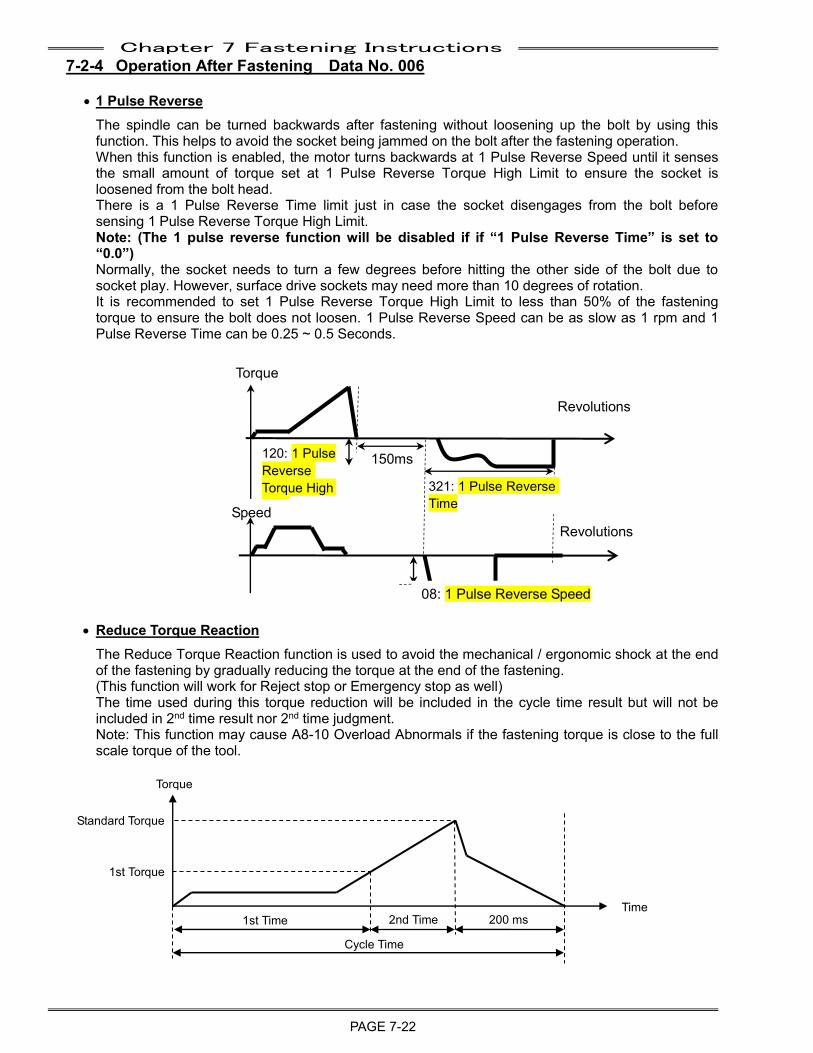
Chapter 7 Fastening Instructions
PAGE 7-22
7-2-4 Operation After Fastening Data No. 006
• 1 Pulse Reverse The spindle can be turned backwards after fastening without loosening up the bolt by using this function. This helps to avoid the socket being jammed on the bolt after the fastening operation. When this function is enabled, the motor turns backwards at 1 Pulse Reverse Speed until it senses the small amount of torque set at 1 Pulse Reverse Torque High Limit to ensure the socket is loosened from the bolt head. There is a 1 Pulse Reverse Time limit just in case the socket disengages from the bolt before sensing 1 Pulse Reverse Torque High Limit. Note: (The 1 pulse reverse function will be disabled if if “1 Pulse Reverse Time” is set to “0.0”) Normally, the socket needs to turn a few degrees before hitting the other side of the bolt due to socket play. However, surface drive sockets may need more than 10 degrees of rotation. It is recommended to set 1 Pulse Reverse Torque High Limit to less than 50% of the fastening torque to ensure the bolt does not loosen. 1 Pulse Reverse Speed can be as slow as 1 rpm and 1 Pulse Reverse Time can be 0.25 ~ 0.5 Seconds.
Revolutions
Revolutions
• Reduce Torque Reaction The Reduce Torque Reaction function is used to avoid the mechanical / ergonomic shock at the end of the fastening by gradually reducing the torque at the end of the fastening. (This function will work for Reject stop or Emergency stop as well) The time used during this torque reduction will be included in the cycle time result but will not be included in 2nd time result nor 2nd time judgment. Note: This function may cause A8-10 Overload Abnormals if the fastening torque is close to the full scale torque of the tool.
Torque
Time
Standard Torque
1st Torque
1st Time 2nd Time 200 ms
Cycle Time
Torque
Speed
150msec
120: 1 Pulse Reverse Torque High Limit
321: 1 Pulse Reverse Time
08: 1 Pulse Reverse Speed
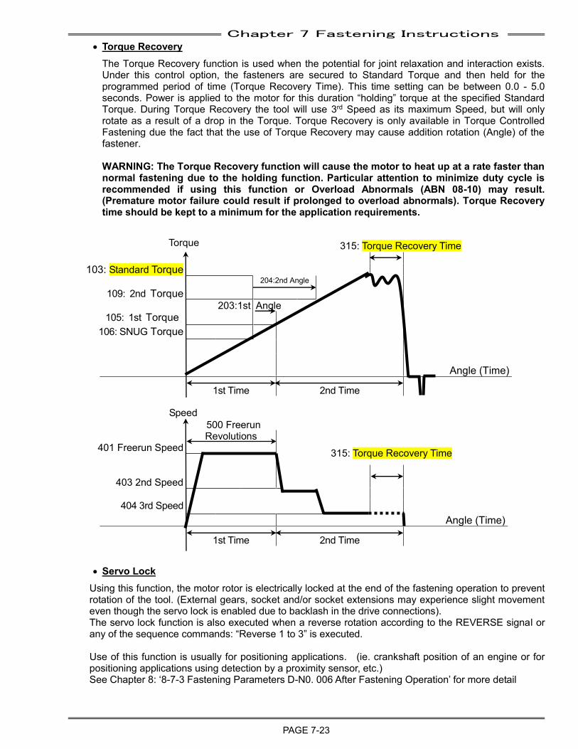
Chapter 7 Fastening Instructions
PAGE 7-23
• Torque Recovery The Torque Recovery function is used when the potential for joint relaxation and interaction exists. Under this control option, the fasteners are secured to Standard Torque and then held for the programmed period of time (Torque Recovery Time). This time setting can be between 0.0 - 5.0 seconds. Power is applied to the motor for this duration “holding” torque at the specified Standard Torque. During Torque Recovery the tool will use 3rd Speed as its maximum Speed, but will only rotate as a result of a drop in the Torque. Torque Recovery is only available in Torque Controlled Fastening due the fact that the use of Torque Recovery may cause addition rotation (Angle) of the fastener. WARNING: The Torque Recovery function will cause the motor to heat up at a rate faster than normal fastening due to the holding function. Particular attention to minimize duty cycle is recommended if using this function or Overload Abnormals (ABN 08-10) may result. (Premature motor failure could result if prolonged to overload abnormals). Torque Recovery time should be kept to a minimum for the application requirements.
103: Standard Torque
204:2nd Angle 109: 2nd Torque
203:1st Angle 105: 1st Torque
106: SNUG Torque
Angle (Time)
1st Time 2nd Time
500 Freerun Revolutions
401 Freerun Speed
403 2nd Speed
404 3rd Speed Angle (Time) 1st Time 2nd Time
• Servo Lock
Using this function, the motor rotor is electrically locked at the end of the fastening operation to prevent rotation of the tool. (External gears, socket and/or socket extensions may experience slight movement even though the servo lock is enabled due to backlash in the drive connections). The servo lock function is also executed when a reverse rotation according to the REVERSE signal or any of the sequence commands: “Reverse 1 to 3” is executed. Use of this function is usually for positioning applications. (ie. crankshaft position of an engine or for positioning applications using detection by a proximity sensor, etc.) See Chapter 8: ‘8-7-3 Fastening Parameters D-N0. 006 After Fastening Operation’ for more detail
315: Torque Recovery Time
Speed
315: Torque Recovery Time
Torque
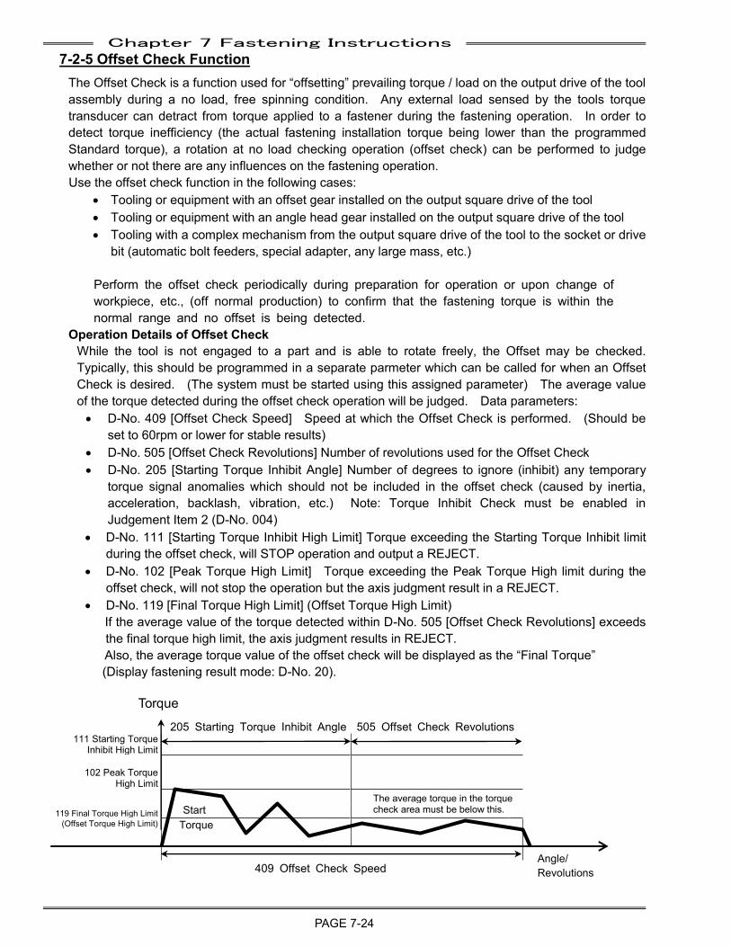
Chapter 7 Fastening Instructions
PAGE 7-24
7-2-5 Offset Check Function The Offset Check is a function used for “offsetting” prevailing torque / load on the output drive of the tool assembly during a no load, free spinning condition. Any external load sensed by the tools torque transducer can detract from torque applied to a fastener during the fastening operation. In order to detect torque inefficiency (the actual fastening installation torque being lower than the programmed Standard torque), a rotation at no load checking operation (offset check) can be performed to judge whether or not there are any influences on the fastening operation. Use the offset check function in the following cases:
• Tooling or equipment with an offset gear installed on the output square drive of the tool • Tooling or equipment with an angle head gear installed on the output square drive of the tool • Tooling with a complex mechanism from the output square drive of the tool to the socket or drive
bit (automatic bolt feeders, special adapter, any large mass, etc.)
Perform the offset check periodically during preparation for operation or upon change of workpiece, etc., (off normal production) to confirm that the fastening torque is within the normal range and no offset is being detected.
Operation Details of Offset Check While the tool is not engaged to a part and is able to rotate freely, the Offset may be checked. Typically, this should be programmed in a separate parmeter which can be called for when an Offset Check is desired. (The system must be started using this assigned parameter) The average value of the torque detected during the offset check operation will be judged. Data parameters: • D-No. 409 [Offset Check Speed] Speed at which the Offset Check is performed. (Should be
set to 60rpm or lower for stable results) • D-No. 505 [Offset Check Revolutions] Number of revolutions used for the Offset Check • D-No. 205 [Starting Torque Inhibit Angle] Number of degrees to ignore (inhibit) any temporary
torque signal anomalies which should not be included in the offset check (caused by inertia, acceleration, backlash, vibration, etc.) Note: Torque Inhibit Check must be enabled in Judgement Item 2 (D-No. 004)
• D-No. 111 [Starting Torque Inhibit High Limit] Torque exceeding the Starting Torque Inhibit limit during the offset check, will STOP operation and output a REJECT.
• D-No. 102 [Peak Torque High Limit] Torque exceeding the Peak Torque High limit during the offset check, will not stop the operation but the axis judgment result in a REJECT.
• D-No. 119 [Final Torque High Limit] (Offset Torque High Limit) If the average value of the torque detected within D-No. 505 [Offset Check Revolutions] exceeds the final torque high limit, the axis judgment results in REJECT. Also, the average torque value of the offset check will be displayed as the “Final Torque” (Display fastening result mode: D-No. 20).
205 Starting Torque Inhibit Angle 505 Offset Check Revolutions 111 Starting Torque
Inhibit High Limit
102 Peak Torque
High Limit
The average torque in the torque 119 Final Torque High Limit Start check area must be below this.
(Offset Torque High Limit) Torque
409 Offset Check Speed
Torque
Angle/ Revolutions

Chapter 7 Fastening Instructions
PAGE 7-25
7-3 Judgement Functions (Judge Item 1 / Judge Item 2) The AFC3000 System is user programmable to select and judge the limits for torque, angle and the number of revolutions. With the MULTI system, JUDGMENT is made from the internal sequence operation according to the sequence commands (At the end of steps, the END command and DATA REPORT command) In a Single System setup, the sequence is automatic and cannot be changed (1,2 or 3 step fastening) and judgment is at the end of cycle.
Judgment Outputs Description of Function/Usage
REJECT
This is output under the following conditions. ・ When a fastening result falls outside a judgment limits at on any spindle. (Torque, Angle,
Time, Rundown Revolutions, Rate, etc) ・ When the PLC I/O input signal “BYPASS” is set “ON” during the fastening cycle. ・ When the sequence operation is started with the PLC I/O input signal “BYPASS” of all
Units being set “ON”.
ACCEPT This is output when the cycle ends with the fastening results (Torque, Angle, Time, Rundown Revolutions, Rate, etc) being within the judgment limits on ALL spindles connected.
ABNORMAL This is output when a system error occurs at the start of the cycle or during the sequence operation.
STOP This is output when the PLC I/O input signal “STOP” is set “ON” during cycle. Specific to a MULTI system: this is output if a sequence calls a parameter that has an error in it (ie. the parameter is setup as a “1 STEP” fastening and the sequence calls 2nd STEP)
RESET STOP This is output when the PLC I/O input signal “RESET” is set “ON” during the cycle or when the RESET button on the display of the MASTER Spindle is pressed.
START OFF This is output when the PLC I/O input signal “START” is set “OFF” during cycle with “Deadman” being set as the start method in the sequence setup. (The start method is set at Sequence Setting of the AFC3000 User Console.)
IN CYCLE This is output anytime a “Data Report” sequence command is used in the sequence program while in cycle.
BYPASS Output when the PLC I/O input signal “BYPASS” is turned ON before the fastening cycle or when the fastening cycle is started and the RUN/BYPASS switch on the MFC unit is switched in the BYPASS position.
Reject judgment is made when the fastening results fall OUTSIDE of the preset HIGH / LOW limits programmed in the parameter set. (Torque, Angle, Time, Rundown Revolutions, Rate, etc)
• High Limit value (REJECT): A value exceeding the High Limit has been detected • Low Limit value (REJECT): A value less than the Low Limit has been detected • Values that fall WITHIN the High / Low limit setting are deemed ACCEPTS.
Be careful fastening judgments are performed. The fastening parameters D-No. 003 “Output Judgment Item 1” and D-No. 004 “Output Judgment Item 2” allow the selection of which items are judged. Make sure the items you wish to judge are selected.
Caution
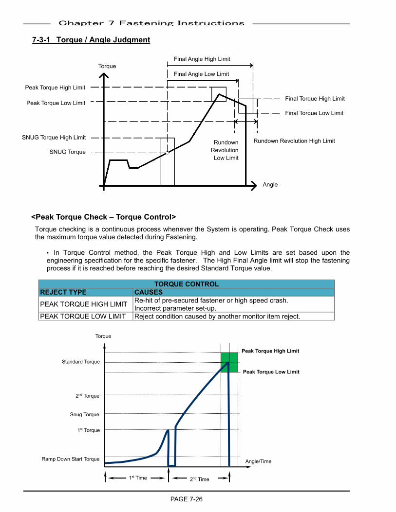
Chapter 7 Fastening Instructions
PAGE 7-26
7-3-1 Torque / Angle Judgment
<Peak Torque Check – Torque Control>
Torque checking is a continuous process whenever the System is operating. Peak Torque Check uses the maximum torque value detected during Fastening.
P In Torque Control method, the Peak Torque High and Low Limits are set based upon the engineering specification for the specific fastener. The High Final Angle limit will stop the fastening process if it is reached before reaching the desired Standard Torque value.
TORQUE CONTROL REJECT TYPE CAUSES
PEAK TORQUE HIGH LIMIT Re-hit of pre-secured fastener or high speed crash. Incorrect parameter set-up.
PEAK TORQUE LOW LIMIT Reject condition caused by another monitor item reject.
Peak Torque High Limit
Peak Torque Low Limit
Rundown Revolution Low Limit
Rundown Revolution High Limit
Final Torque High Limit
Final Torque Low Limit
SNUG Torque High Limit
SNUG Torque
Torque Final Angle High Limit
Angle
Final Angle Low Limit
Snug Torque
1st Time 2nd Time
Standard Torque
Ramp Down Start Torque
1st Torque
2nd Torque
Torque
Angle/Time
Peak Torque High Limit
Peak Torque Low Limit
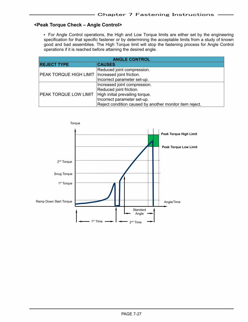
Chapter 7 Fastening Instructions
PAGE 7-27
<Peak Torque Check – Angle Control>
P For Angle Control operations, the High and Low Torque limits are either set by the engineering specification for that specific fastener or by determining the acceptable limits from a study of known good and bad assemblies. The High Torque limit will stop the fastening process for Angle Control operations if it is reached before attaining the desired angle.
ANGLE CONTROL REJECT TYPE CAUSES
PEAK TORQUE HIGH LIMIT Reduced joint compression. Increased joint friction. Incorrect parameter set-up.
PEAK TORQUE LOW LIMIT
Increased joint compression. Reduced joint friction. High initial prevailing torque. Incorrect parameter set-up. Reject condition caused by another monitor item reject.
Peak Torque High Limit
Peak Torque Low Limit
Torque
Angle/Time
Snug Torque
Ramp Down Start Torque
1st Torque
2nd Torque
2nd Time 1st Time
Standard Angle
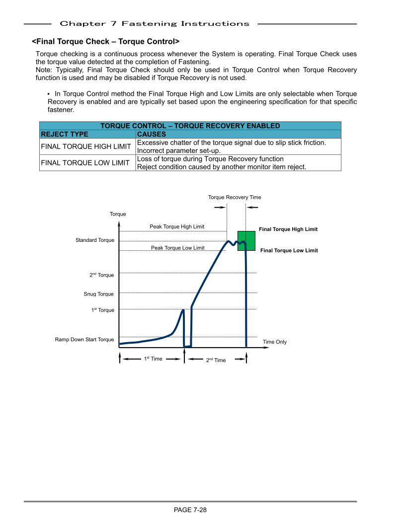
Chapter 7 Fastening Instructions
PAGE 7-28
<Final Torque Check – Torque Control> Torque checking is a continuous process whenever the System is operating. Final Torque Check uses the torque value detected at the completion of Fastening. Note: Typically, Final Torque Check should only be used in Torque Control when Torque Recovery function is used and may be disabled if Torque Recovery is not used.
P In Torque Control method the Final Torque High and Low Limits are only selectable when Torque Recovery is enabled and are typically set based upon the engineering specification for that specific fastener.
TORQUE CONTROL – TORQUE RECOVERY ENABLED REJECT TYPE CAUSES
FINAL TORQUE HIGH LIMIT Excessive chatter of the torque signal due to slip stick friction. Incorrect parameter set-up.
FINAL TORQUE LOW LIMIT Loss of torque during Torque Recovery function Reject condition caused by another monitor item reject.
Snug Torque
Standard Torque
Ramp Down Start Torque
1st Torque
2nd Torque
Torque
Time Only
Peak Torque High Limit
Peak Torque Low Limit
1st Time 2nd Time
Final Torque High Limit
Final Torque Low Limit
Torque Recovery Time
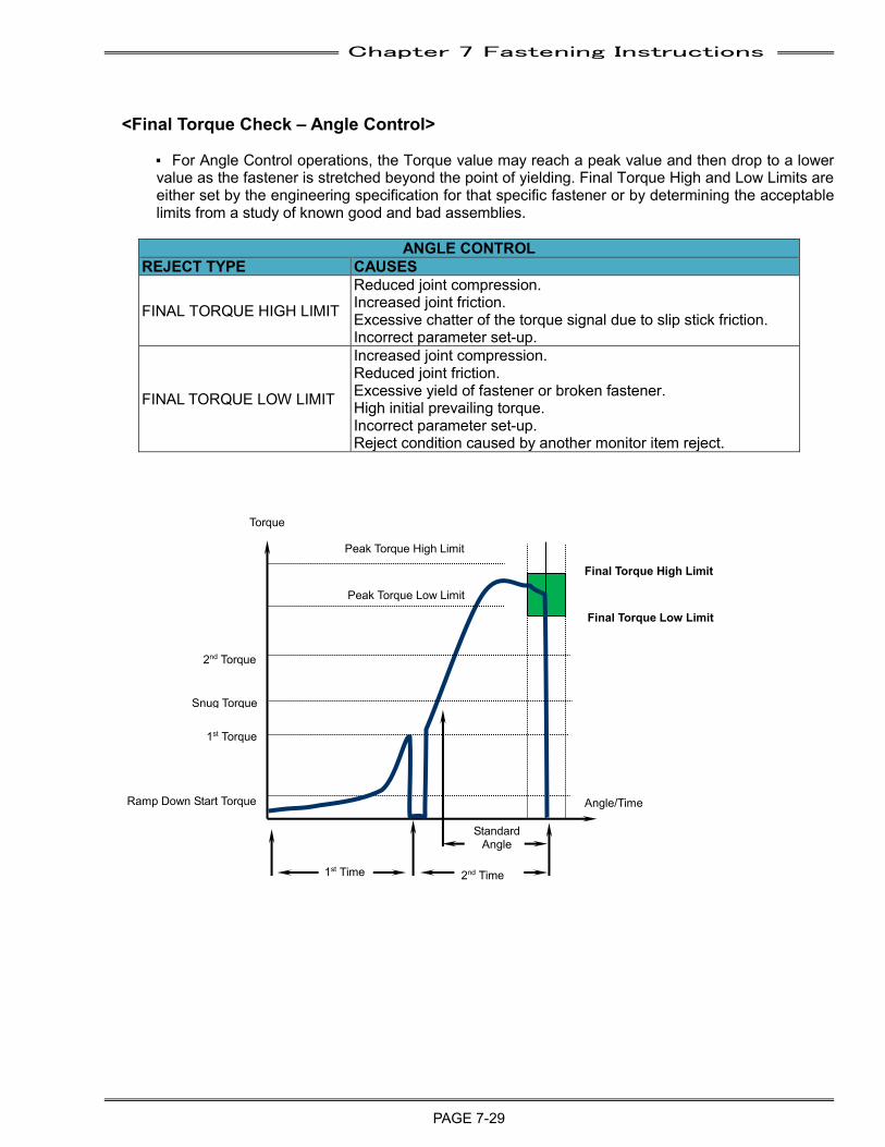
Chapter 7 Fastening Instructions
PAGE 7-29
<Final Torque Check – Angle Control> P For Angle Control operations, the Torque value may reach a peak value and then drop to a lower value as the fastener is stretched beyond the point of yielding. Final Torque High and Low Limits are either set by the engineering specification for that specific fastener or by determining the acceptable limits from a study of known good and bad assemblies.
ANGLE CONTROL REJECT TYPE CAUSES
FINAL TORQUE HIGH LIMIT
Reduced joint compression. Increased joint friction. Excessive chatter of the torque signal due to slip stick friction. Incorrect parameter set-up.
FINAL TORQUE LOW LIMIT
Increased joint compression. Reduced joint friction. Excessive yield of fastener or broken fastener. High initial prevailing torque. Incorrect parameter set-up. Reject condition caused by another monitor item reject.
Peak Torque High Limit
Peak Torque Low Limit
Torque
Angle/Time
Final Torque High Limit
Final Torque Low Limit
Snug Torque
Ramp Down Start Torque
1st Torque
2nd Torque
2nd Time 1st Time
Standard Angle
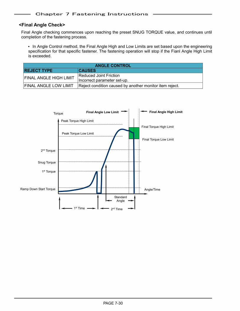
Chapter 7 Fastening Instructions
PAGE 7-30
<Final Angle Check>
Final Angle checking commences upon reaching the preset SNUG TORQUE value, and continues until completion of the fastening process.
P In Angle Control method, the Final Angle High and Low Limits are set based upon the engineering specification for that specific fastener. The fastening operation will stop if the Fianl Angle High Limit is exceeded.
ANGLE CONTROL REJECT TYPE CAUSES
FINAL ANGLE HIGH LIMIT Reduced Joint Friction Incorrect parameter set-up.
FINAL ANGLE LOW LIMIT Reject condition caused by another monitor item reject.
Peak Torque High Limit
Peak Torque Low Limit
Torque
Angle/Time
Snug Torque
Ramp Down Start Torque
1st Torque
2nd Torque
Final Torque High Limit
Final Torque Low Limit
2nd Time 1st Time
Standard Angle
Final Angle High Limit Final Angle Low Limit
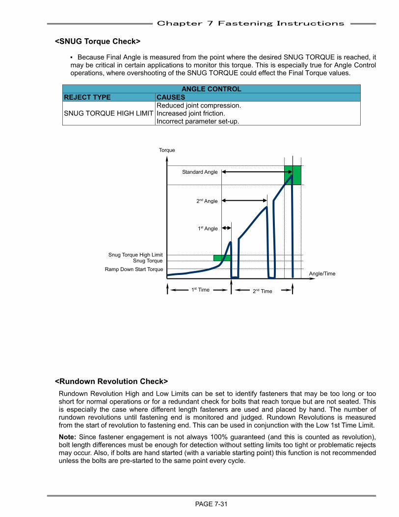
Chapter 7 Fastening Instructions
PAGE 7-31
<SNUG Torque Check>
P Because Final Angle is measured from the point where the desired SNUG TORQUE is reached, it may be critical in certain applications to monitor this torque. This is especially true for Angle Control operations, where overshooting of the SNUG TORQUE could effect the Final Torque values.
ANGLE CONTROL REJECT TYPE CAUSES
SNUG TORQUE HIGH LIMIT Reduced joint compression. Increased joint friction. Incorrect parameter set-up.
<Rundown Revolution Check> Rundown Revolution High and Low Limits can be set to identify fasteners that may be too long or too short for normal operations or for a redundant check for bolts that reach torque but are not seated. This is especially the case where different length fasteners are used and placed by hand. The number of rundown revolutions until fastening end is monitored and judged. Rundown Revolutions is measured from the start of revolution to fastening end. This can be used in conjunction with the Low 1st Time Limit. Note: Since fastener engagement is not always 100% guaranteed (and this is counted as revolution), bolt length differences must be enough for detection without setting limits too tight or problematic rejects may occur. Also, if bolts are hand started (with a variable starting point) this function is not recommended unless the bolts are pre-started to the same point every cycle.
Torque
Angle/Time
1st Time 2nd Time
Standard Angle
Ramp Down Start Torque
1st Angle
2nd Angle
Snug Torque Snug Torque High Limit
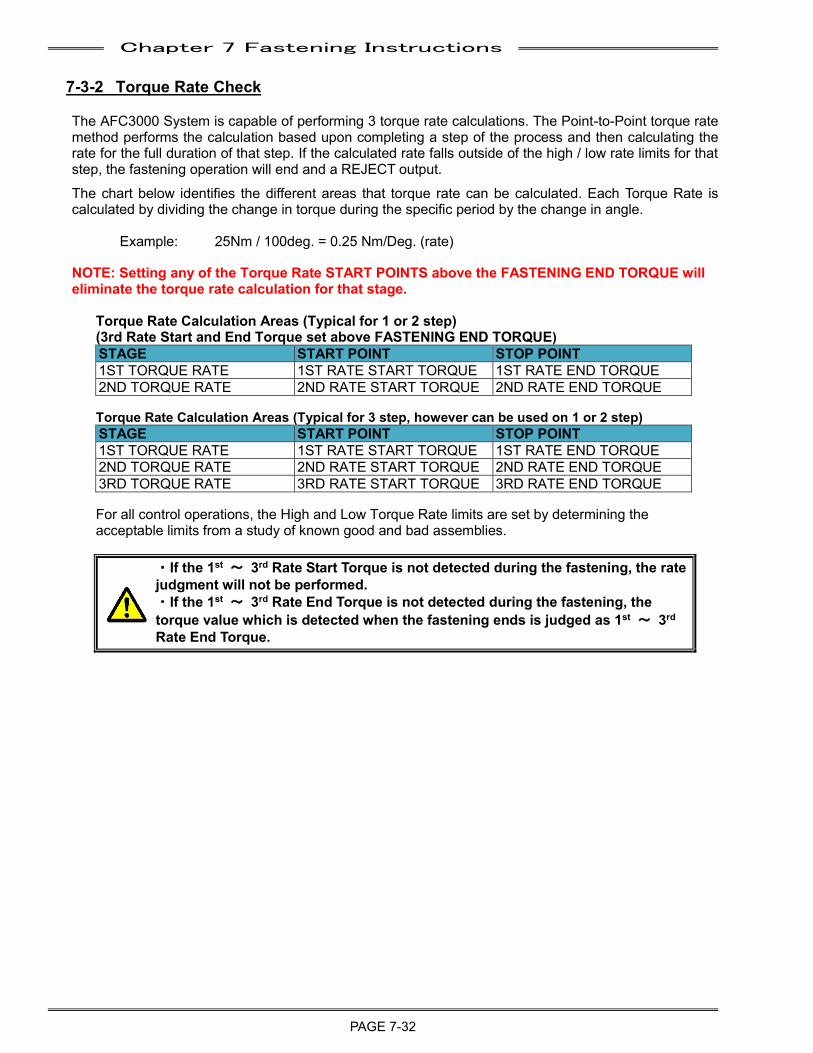
Chapter 7 Fastening Instructions
PAGE 7-32
7-3-2 Torque Rate Check
The AFC3000 System is capable of performing 3 torque rate calculations. The Point-to-Point torque rate method performs the calculation based upon completing a step of the process and then calculating the rate for the full duration of that step. If the calculated rate falls outside of the high / low rate limits for that step, the fastening operation will end and a REJECT output.
The chart below identifies the different areas that torque rate can be calculated. Each Torque Rate is calculated by dividing the change in torque during the specific period by the change in angle.
Example: 25Nm / 100deg. = 0.25 Nm/Deg. (rate)
NOTE: Setting any of the Torque Rate START POINTS above the FASTENING END TORQUE will eliminate the torque rate calculation for that stage.
Torque Rate Calculation Areas (Typical for 1 or 2 step) (3rd Rate Start and End Torque set above FASTENING END TORQUE) STAGE START POINT STOP POINT 1ST TORQUE RATE 1ST RATE START TORQUE 1ST RATE END TORQUE 2ND TORQUE RATE 2ND RATE START TORQUE 2ND RATE END TORQUE Torque Rate Calculation Areas (Typical for 3 step, however can be used on 1 or 2 step) STAGE START POINT STOP POINT 1ST TORQUE RATE 1ST RATE START TORQUE 1ST RATE END TORQUE 2ND TORQUE RATE 2ND RATE START TORQUE 2ND RATE END TORQUE 3RD TORQUE RATE 3RD RATE START TORQUE 3RD RATE END TORQUE For all control operations, the High and Low Torque Rate limits are set by determining the acceptable limits from a study of known good and bad assemblies.
・If the 1st ~ 3rd Rate Start Torque is not detected during the fastening, the rate judgment will not be performed. ・If the 1st ~ 3rd Rate End Torque is not detected during the fastening, the torque value which is detected when the fastening ends is judged as 1st ~ 3rd Rate End Torque.
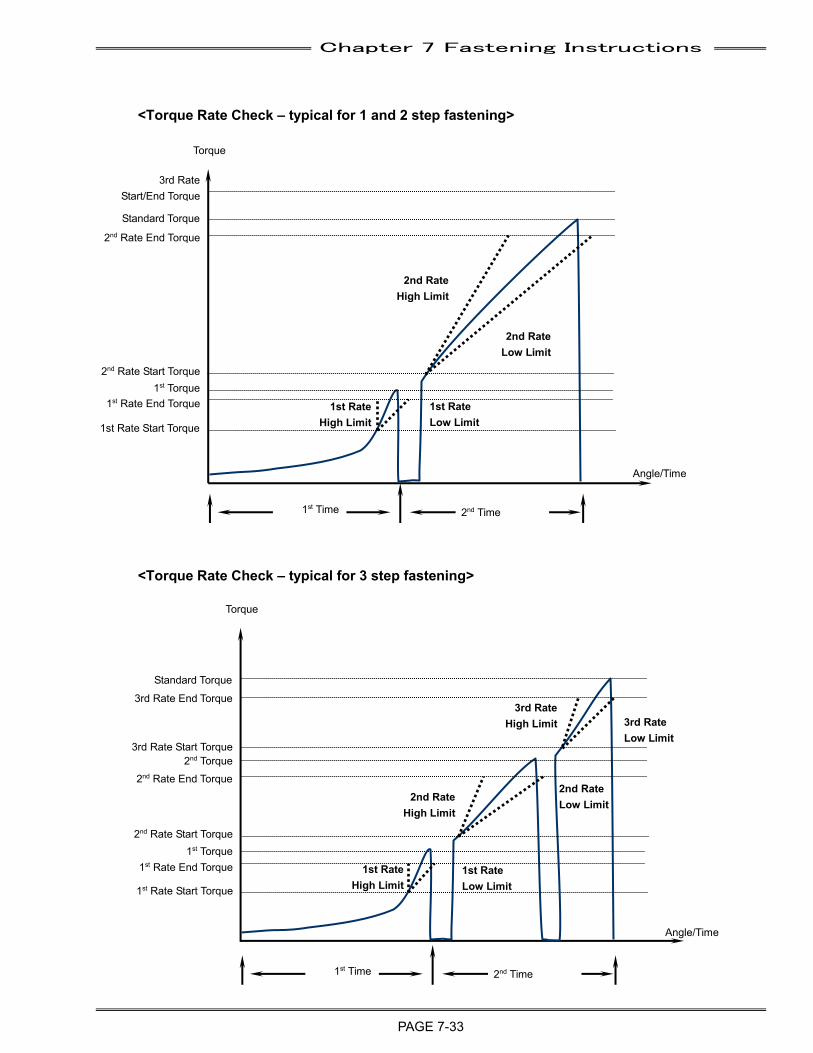
Chapter 7 Fastening Instructions
PAGE 7-33
<Torque Rate Check – typical for 1 and 2 step fastening>
<Torque Rate Check – typical for 3 step fastening>
3rd Rate Start/End Torque
Torque
Angle/Time
1st Time 2nd Time
2nd Rate Start Torque
Standard Torque
1st Rate Start Torque
1st Rate End Torque 1st Rate Low Limit
2nd Rate High Limit
1st Rate High Limit
2nd Rate Low Limit
2nd Rate End Torque
Torque
Angle/Time
1st Time 2nd Time
2nd Rate Start Torque
Standard Torque
1st Rate Start Torque
1st Rate End Torque 1st Rate Low Limit
3rd Rate High Limit
2nd Rate High Limit
1st Rate High Limit
2nd Rate Low Limit
3rd Rate Low Limit
3rd Rate Start Torque
2nd Rate End Torque
3rd Rate End Torque
1st Torque
1st Torque
2nd Torque
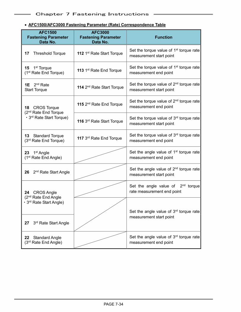
Chapter 7 Fastening Instructions
PAGE 7-34
• AFC1500/AFC3000 Fastening Parameter (Rate) Correspondence Table
AFC1500 Fastening Parameter
Data No.
AFC3000 Fastening Parameter
Data No. Function
17 Threshold Torque 112 1st Rate Start Torque Set the torque value of 1st torque rate measurement start point
15 1st Torque (1st Rate End Torque) 113 1st Rate End Torque
Set the torque value of 1st torque rate measurement end point
1E 2nd Rate Start Torque 114 2nd Rate Start Torque
Set the torque value of 2nd torque rate measurement start point
18 CROS Torque (2nd Rate End Torque ・3rd Rate Start Torque)
115 2nd Rate End Torque Set the torque value of 2nd torque rate measurement end point
116 3rd Rate Start Torque Set the torque value of 3rd torque rate measurement start point
13 Standard Torque (3rd Rate End Torque) 117 3rd Rate End Torque
Set the torque value of 3rd torque rate measurement end point
23 1st Angle (1st Rate End Angle)
Set the angle value of 1st torque rate measurement end point
26 2nd Rate Start Angle Set the angle value of 2nd torque rate measurement start point
24 CROS Angle (2nd Rate End Angle ・3rd Rate Start Angle)
Set the angle value of 2nd torque rate measurement end point
Set the angle value of 3rd torque rate measurement start point
27 3rd Rate Start Angle
22 Standard Angle (3rd Rate End Angle)
Set the angle value of 3rd torque rate measurement end point
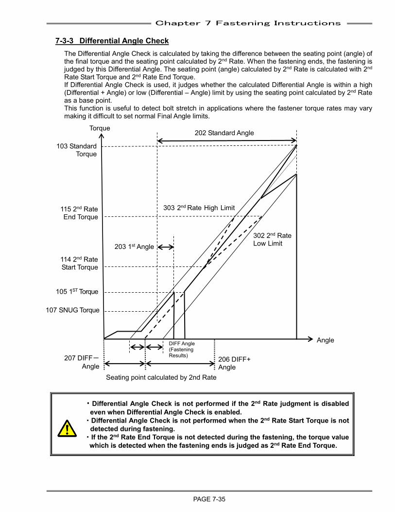
Chapter 7 Fastening Instructions
PAGE 7-35
7-3-3 Differential Angle Check The Differential Angle Check is calculated by taking the difference between the seating point (angle) of the final torque and the seating point calculated by 2nd Rate. When the fastening ends, the fastening is judged by this Differential Angle. The seating point (angle) calculated by 2nd Rate is calculated with 2nd Rate Start Torque and 2nd Rate End Torque. If Differential Angle Check is used, it judges whether the calculated Differential Angle is within a high (Differential + Angle) or low (Differential – Angle) limit by using the seating point calculated by 2nd Rate as a base point. This function is useful to detect bolt stretch in applications where the fastener torque rates may vary making it difficult to set normal Final Angle limits.
・Differential Angle Check is not performed if the 2nd Rate judgment is disabled even when Differential Angle Check is enabled.
・Differential Angle Check is not performed when the 2nd Rate Start Torque is not detected during fastening.
・If the 2nd Rate End Torque is not detected during the fastening, the torque value which is detected when the fastening ends is judged as 2nd Rate End Torque.
Torque 202 Standard Angle
115 2nd Rate End Torque
114 2nd Rate Start Torque
303 2nd Rate High Limit レート 2 上限
302 2nd Rate Low Limit
Rate レート2下限
105 1ST Torque
107 SNUG Torque
DIFF Angle (Fastening Results)
Angle
206 DIFF+ Angle
207 DIFF- Angle
Seating point calculated by 2nd Rate
103 Standard Torque
203 1st Angle
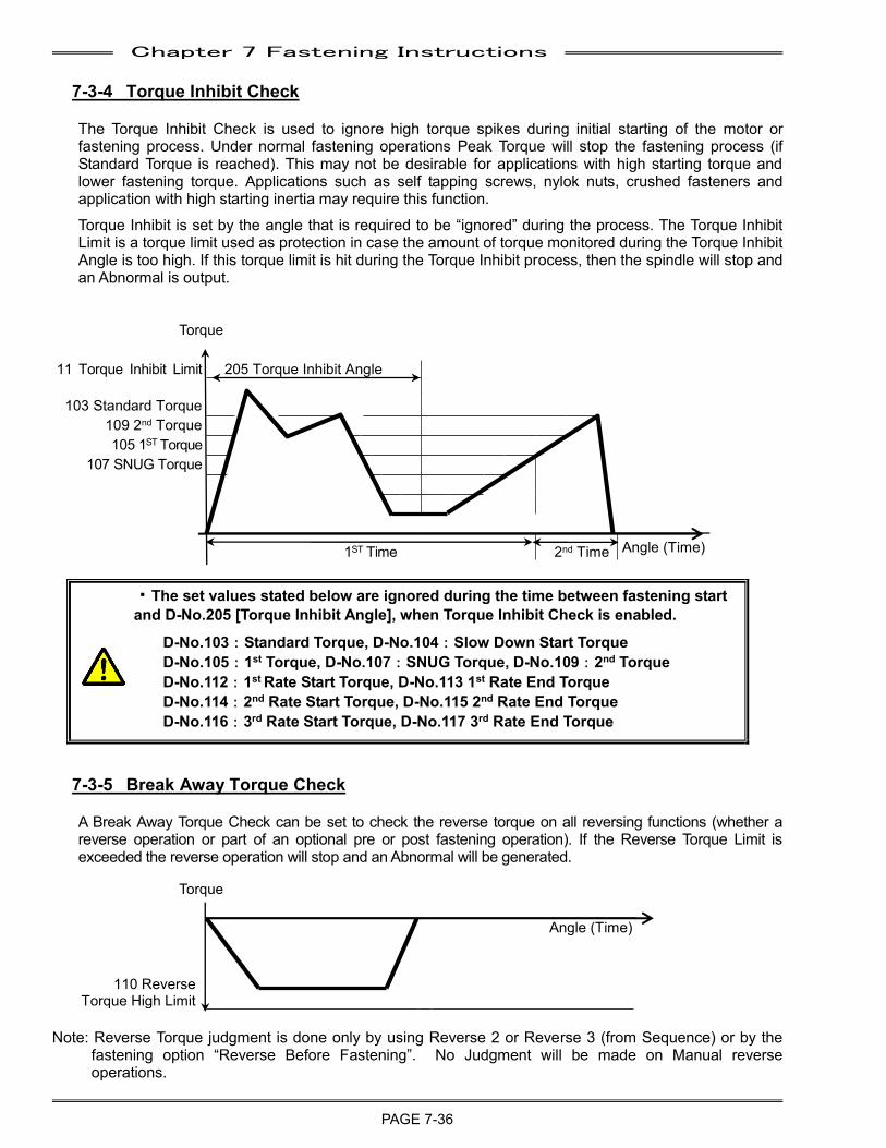
Chapter 7 Fastening Instructions
PAGE 7-36
7-3-4 Torque Inhibit Check
The Torque Inhibit Check is used to ignore high torque spikes during initial starting of the motor or fastening process. Under normal fastening operations Peak Torque will stop the fastening process (if Standard Torque is reached). This may not be desirable for applications with high starting torque and lower fastening torque. Applications such as self tapping screws, nylok nuts, crushed fasteners and application with high starting inertia may require this function.
Torque Inhibit is set by the angle that is required to be “ignored” during the process. The Torque Inhibit Limit is a torque limit used as protection in case the amount of torque monitored during the Torque Inhibit Angle is too high. If this torque limit is hit during the Torque Inhibit process, then the spindle will stop and an Abnormal is output.
111 Torque Inhibit Limit 205 Torque Inhibit Angle
103 Standard Torque
109 2nd Torque
105 1ST Torque
107 SNUG Torque
1ST Time 2nd Time Angle (Time)
・The set values stated below are ignored during the time between fastening start and D-No.205 [Torque Inhibit Angle], when Torque Inhibit Check is enabled.
D-No.103:Standard Torque, D-No.104:Slow Down Start Torque D-No.105:1st Torque, D-No.107:SNUG Torque, D-No.109:2nd Torque D-No.112:1st Rate Start Torque, D-No.113 1st Rate End Torque D-No.114:2nd Rate Start Torque, D-No.115 2nd Rate End Torque D-No.116:3rd Rate Start Torque, D-No.117 3rd Rate End Torque
7-3-5 Break Away Torque Check
A Break Away Torque Check can be set to check the reverse torque on all reversing functions (whether a reverse operation or part of an optional pre or post fastening operation). If the Reverse Torque Limit is exceeded the reverse operation will stop and an Abnormal will be generated.
Angle (Time)
110 Reverse
Torque High Limit
Note: Reverse Torque judgment is done only by using Reverse 2 or Reverse 3 (from Sequence) or by the fastening option “Reverse Before Fastening”. No Judgment will be made on Manual reverse operations.
Torque
Torque
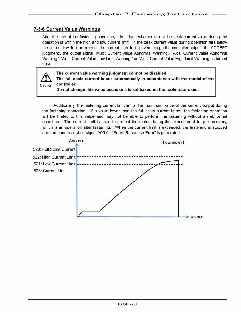
Chapter 7 Fastening Instructions
PAGE 7-37
7-3-6 Current Value Warnings After the end of the fastening operation, it is judged whether or not the peak current value during the operation is within the high and low current limit. If the peak current value during operation falls below the current low limit or exceeds the current high limit, ( even though the controller outputs the ACCEPT judgment), the output signal “Multi: Current Value Abnormal Warning,” “Axis: Current Value Abnormal Warning,” “Axis: Current Value Low Limit Warning,” or “Axis: Current Value High Limit Warning” is turned “ON.”
The current value warning judgment cannot be disabled. The full scale current is set automatically in accordance with the model of the controller. Do not change this value because it is set based on the tool/motor used.
Additionally, the fastening current limit limits the maximum value of the current output during
the fastening operation. If a value lower than the full scale current is set, the fastening operation will be limited to this value and may not be able to perform the fastening without an abnormal condition. The current limit is used to protect the motor during the execution of torque recovery, which is an operation after fastening. When the current limit is exceeded, the fastening is stopped and the abnormal state signal A05-01 “Servo Response Error” is generated.
520: Full Scale Current
523: Current Limit
522: High Current Limit 521: Low Current Limit
Caution
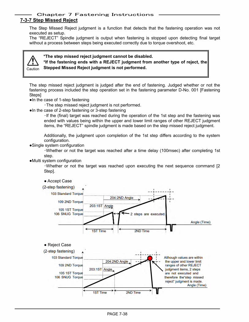
Chapter 7 Fastening Instructions
PAGE 7-38
7-3-7 Step Missed Reject The Step Missed Reject judgment is a function that detects that the fastening operation was not executed as setup. The “REJECT” Spindle judgment is output when fastening is stopped upon detecting final target without a process between steps being executed correctly due to torque overshoot, etc.
*The step missed reject judgment cannot be disabled. *If the fastening ends with a REJECT judgment from another type of reject, the Stepped Missed Reject judgment is not performed.
The step missed reject judgment is judged after the end of fastening. Judged whether or not the fastening process included the step operation set in the fastening parameter D-No. 001 [Fastening Steps] ●In the case of 1-step fastening
・The step missed reject judgment is not performed. ●In the case of 2-step fastening or 3-step fastening
・If the (final) target was reached during the operation of the 1st step and the fastening was ended with values being within the upper and lower limit ranges of other REJECT judgment items, the “REJECT” spindle judgment is made based on the step missed reject judgment. Additionally, the judgment upon completion of the 1st step differs according to the system configuration.
●Single system configuration ・Whether or not the target was reached after a time delay (100msec) after completing 1st step.
●Multi system configuration ・Whether or not the target was reached upon executing the next sequence command [2 Step]. ● Accept Case
● Reject Case
Caution
Chapter 7 Fastening Instructions
PAGE 7-39
7-4 Fastening Speed &Time The AFC3000 System is user-programmable for operations involving multiple speed settings. The use of multiple speeds during the fastening process aids in socket engagement, achieving cycle time and controlling the applied torque during all stages. Speed functions work the same for Torque Control and Angle Control using any of the previously stated standard Judge functions. Special conditions that affect these operations will be identified in the appropriate section.
1. The system will fasten to the 1ST TORQUE/ANGLE value during the specified 1st TIME limits. The following fastening operations occur during 1st time:
a) The system starts off running at INITIAL SPEED for the period specified by INITIAL TIME. The initial time should be set to mitigate shock occurred at the fastening start time or to engage a bolt and a socket.
b) Upon completion of INITIAL TIME the system switches to FREERUN SPEED for the period specified by FREERUN REVOLUTIONS. The number of revolutions required to complete INITIAL TIME will be deducted from the number of revolutions ran at FREERUN SPEED.
c) Once RAMP DOWN START TORQUE is detected or FREERUN REVOLUTIONS expires, the system will switch from FREERUN SPEED to 1st SPEED and continue to fasten until 1st TORQUE/ANGLE is attained or the 1ST TIME HIGH LIMIT is reached. 1st SPEED is switched right before the fastener is seated and is intended to provide adequate speed to seat the fastener without getting a load to the tool.
2. Upon reaching 1ST Torque/Angle, 1st Time ends and 2ND Time begins. 1ST Torque/Angle is the shift point from 1st Speed to 2nd Speed and the synchronization point prior to commencing the 2nd Step.
3. For a 2 step fastening, the system will fasten to Standard Torque/Angle using 2nd Speed during the specified 2nd Time limits. Standard Torque/Angle must be reached within the 2nd Time Low/High Limits or a reject will occur. The fastening result will output as REJECT (NG). (The time judgment cannot be disabled.)
4. If the 2nd Torque/Angle is detected before the Standard Torque/Angle, the speed is switched from 2nd Speed to 3rd Speed. 2nd Torque/Angle is the synchronization point prior to commencing the 3rd step. For a 3 step fastening, the system will fasten to Standard Torque/Angle using 3rd Torque Speed during the specified 2nd Time Limits. Standard Torque/Angle must be reached within the 2nd Time Low/High Limits or a reject will occur. The fastening result will output as REJECT (NG). (The time judgment cannot be disabled.)
・When D-No.109 [2ND Torque] is set to 95~100% of D-No.103 [Standard Torque], the fastening speed is automatically set to 3rpm after the 2nd Torque is detected. ・This function is not recommended for fastening a soft joint. An Abnormal A.8-10 [OVERLOAD ABNORMAL] may occur.
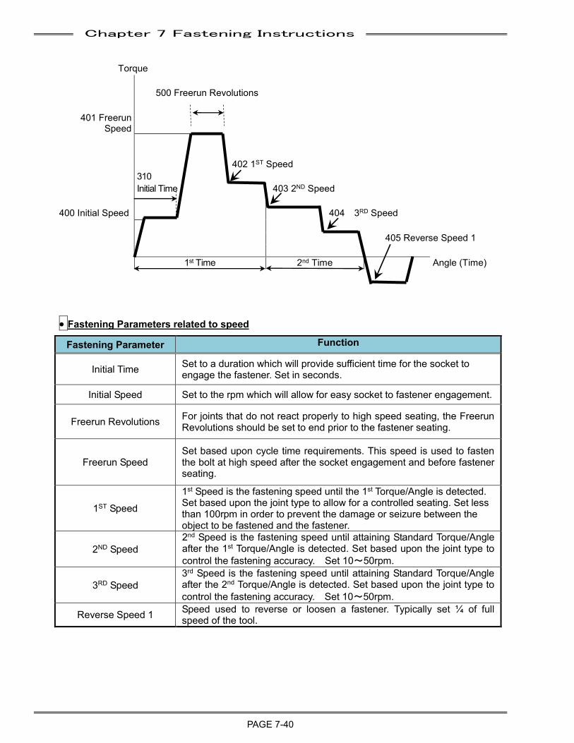
Chapter 7 Fastening Instructions
PAGE 7-40
Torque
500 Freerun Revolutions
401 Freerun Speed
402 1ST Speed
310
Initial Time 403 2ND Speed
400 Initial Speed 404 3RD Speed
405 Reverse Speed 1
1st Time 2nd Time Angle (Time)
• Fastening Parameters related to speed
Fastening Parameter Function
Initial Time Set to a duration which will provide sufficient time for the socket to engage the fastener. Set in seconds.
Initial Speed Set to the rpm which will allow for easy socket to fastener engagement.
Freerun Revolutions For joints that do not react properly to high speed seating, the Freerun Revolutions should be set to end prior to the fastener seating.
Freerun Speed Set based upon cycle time requirements. This speed is used to fasten the bolt at high speed after the socket engagement and before fastener seating.
1ST Speed
1st Speed is the fastening speed until the 1st Torque/Angle is detected. Set based upon the joint type to allow for a controlled seating. Set less than 100rpm in order to prevent the damage or seizure between the object to be fastened and the fastener.
2ND Speed 2nd Speed is the fastening speed until attaining Standard Torque/Angle after the 1st Torque/Angle is detected. Set based upon the joint type to control the fastening accuracy. Set 10~50rpm.
3RD Speed 3rd Speed is the fastening speed until attaining Standard Torque/Angle after the 2nd Torque/Angle is detected. Set based upon the joint type to control the fastening accuracy. Set 10~50rpm.
Reverse Speed 1 Speed used to reverse or loosen a fastener. Typically set ¼ of full speed of the tool.
Chapter 8 System Operation
PAGE 8- 1
Chapter 8: System Operation
8
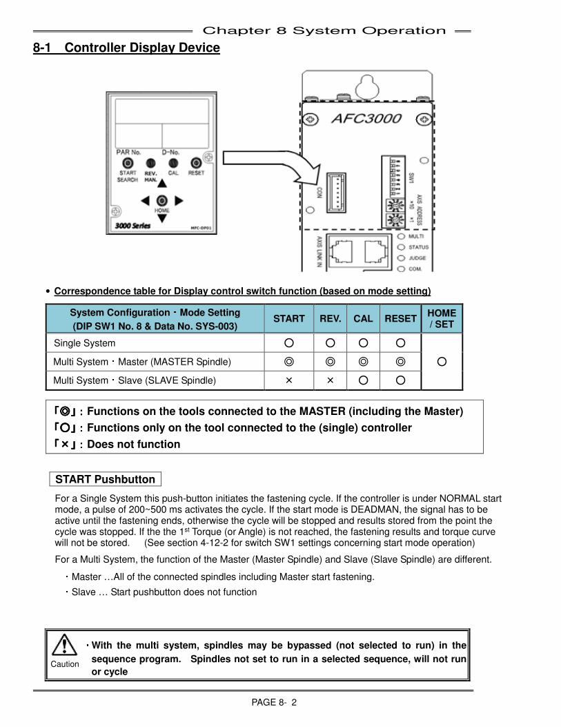
Chapter 8 System Operation
PAGE 8- 2
8-1 Controller Display Device
• Correspondence table for Display control switch function (based on mode setting)
System Configuration・・・
・Mode Setting
(DIP SW1 No. 8 & Data No. SYS-003) START REV. CAL RESET
HOME / SET
Single System ○ ○ ○ ○
○ Multi System:Master (MASTER Spindle) ◎ ◎ ◎ ◎
Multi System:Slave (SLAVE Spindle) × × ○ ○
「「「「◎◎◎◎」:」:」:」:Functions on the tools connected to the MASTER (including the Master)
「「「「○○○○」:」:」:」:Functions only on the tool connected to the (single) controller
「「「「××××」:」:」:」:Does not function
START Pushbutton
For a Single System this push-button initiates the fastening cycle. If the controller is under NORMAL start mode, a pulse of 200~500 ms activates the cycle. If the start mode is DEADMAN, the signal has to be active until the fastening ends, otherwise the cycle will be stopped and results stored from the point the cycle was stopped. If the the 1st Torque (or Angle) is not reached, the fastening results and torque curve will not be stored. (See section 4-12-2 for switch SW1 settings concerning start mode operation)
For a Multi System, the function of the Master (Master Spindle) and Slave (Slave Spindle) are different.
・Master …All of the connected spindles including Master start fastening.
・Slave … Start pushbutton does not function
・
・・
・ With the multi system, spindles may be bypassed (not selected to run) in the
sequence program. Spindles not set to run in a selected sequence, will not run
or cycle Caution
Chapter 8 System Operation
PAGE 8- 3
REV. Pushbutton
For a Single System, while this push-button is depressed, the nutrunner rotates at Reverse 1 Speed (Data-No. 406) in the opposite direction to the programmed fastening direction for the Parameter selected via the PLC “Work Select” inputs.
For a Multi System, the function of the Master (Master Spindle) and Slave (Slave Spindle) are different.
・Master … All of the connected spindles including Master run in reverse (Reverse 1 Speed).
・Slave …..Reverse pushbutton does not function.
・
・・
・ With the multi system, spindles may be bypassed (not selected to run) in the
sequence program. Spindles not set to run in a selected sequence, will not run
or cycle
CAL Pushbutton
Depress this push-button to obtain the CAL voltage level from the tool pre-amplifier. This level is compared to the data stored in memory. If the difference is within the allowed range the JUDGE LED will light in Green, otherwise the JUDGE LED will light in Red. The calibration voltage level is converted to the full-scale torque, according to the parameter setting (Data-No. 100) and is shown in the "DATA" display.
For the Master (Master Spindle) of a Multi System, all of the transducers of connected spindles, including the Master, will be checked.
In addition, when the CAL switch is pressed in the state where D-No. 1 [Torque Voltage Value Indication] of the real time mode (PAGE 8-7) is indicated, the value converted in terms of the potential difference of approximately Δ3.75V is indicated on the upper digits of the display.
・
・・
・Do not press the CAL button during fastening operation. The sudden stopping of
the tool may cause workpiece damage.
RESET Pushbutton
When the RESET push-button is pushed (when not operating), a value close to “0” is indicated on the upper digits of the display and the fastening result output signals are cleared. At the same time, the Zero level of the torque transducer will be checked. If it is within the acceptable range, the JUDGE LED will light in Green. If it is not within range, the JUDGE LED will light in Red.
If the RESET push-button is pushed while fastening, the fastening operation is stopped and the output signals of fastening result and LED displays will be reset.
For the Master (Master Spindle) of a Multi System, all connected spindles, including Master, will be affected (fastening halted, resetting of outputs/results and the checking of the origin level of transducer). If all of the connected spindles zero level is within the acceptable range, the MULTI LED will light in Green. If it is not within range, the MULTI LED will light in Red.
Caution
Chapter 8 System Operation
PAGE 8- 4
“◄” and “►” Pushbutton
Used to change modes (Fastening Result Mode, Set Value Mode, Real Time Mode and Status Mode) when the system is in the RUN state.
Used for moving the cursor or changing the digit of the set value when the system is in the BYPASS state.
“◎◎◎
◎” SET Pushbutton
This push-button is used to set data and to confirm data setting changes when the system is in BYPASS state.
“▲” and “▼” Pushbutton
These push-buttons are used for switching the display data or changing the set Data.
*The content of each display LED will be different based on the controller mode (RUN or BYPASS). Refer to Page 8-5 ”RUN State” and Page 8-14 ”BYPASS State” for the display description in each mode.
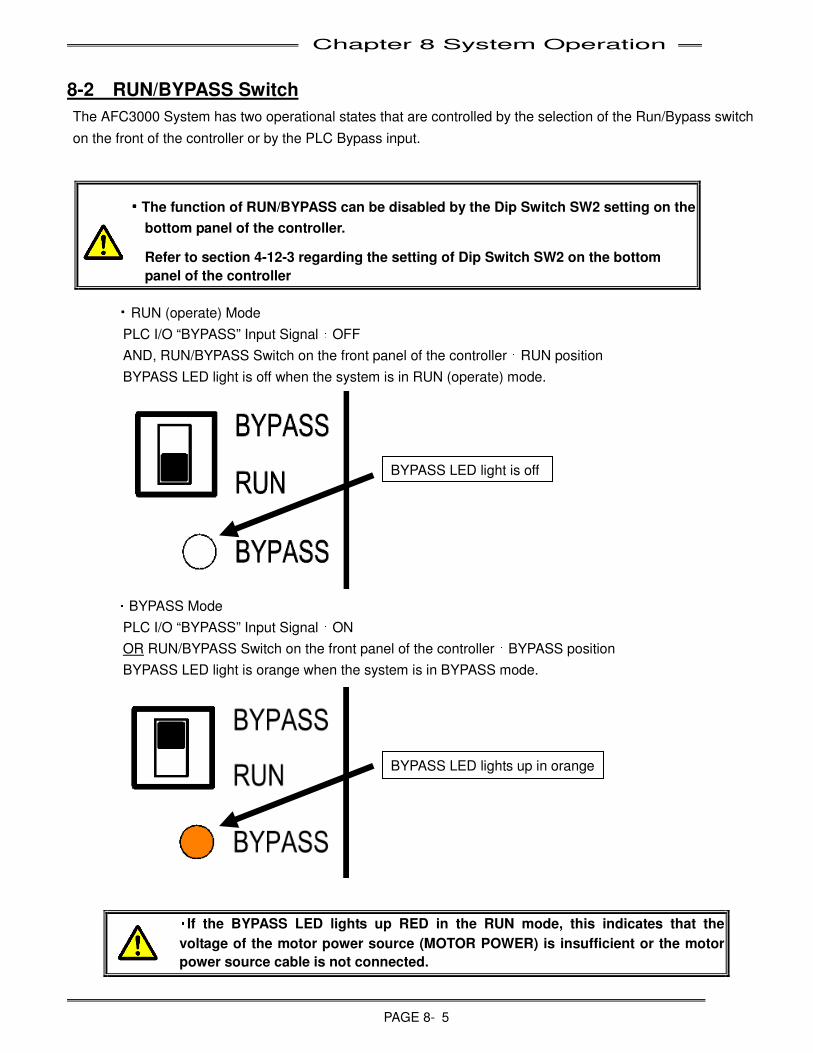
Chapter 8 System Operation
PAGE 8- 5
8-2 RUN/BYPASS Switch
The AFC3000 System has two operational states that are controlled by the selection of the Run/Bypass switch
on the front of the controller or by the PLC Bypass input.
・・・・The function of RUN/BYPASS can be disabled by the Dip Switch SW2 setting on the
bottom panel of the controller.
Refer to section 4-12-3 regarding the setting of Dip Switch SW2 on the bottom
panel of the controller
・RUN (operate) Mode
PLC I/O “BYPASS” Input Signal:OFF
AND, RUN/BYPASS Switch on the front panel of the controller:RUN position
BYPASS LED light is off when the system is in RUN (operate) mode.
・BYPASS Mode
PLC I/O “BYPASS” Input Signal:ON
OR RUN/BYPASS Switch on the front panel of the controller:BYPASS position
BYPASS LED light is orange when the system is in BYPASS mode.
・
・・
・If the BYPASS LED lights up RED in the RUN mode, this indicates that the
voltage of the motor power source (MOTOR POWER) is insufficient or the motor
power source cable is not connected.
BYPASS LED lights up in orange
BYPASS LED light is off
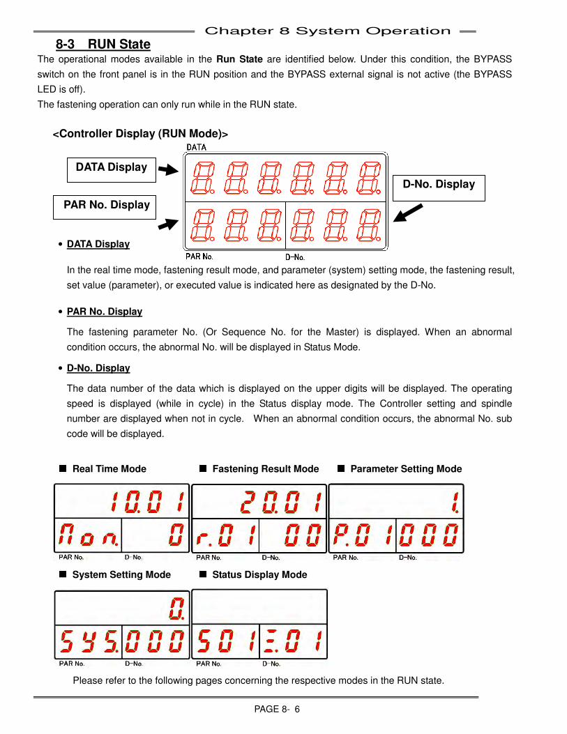
Chapter 8 System Operation
PAGE 8- 6
8-3 RUN State The operational modes available in the Run State are identified below. Under this condition, the BYPASS
switch on the front panel is in the RUN position and the BYPASS external signal is not active (the BYPASS
LED is off).
The fastening operation can only run while in the RUN state.
<Controller Display (RUN Mode)>
• DATA Display
In the real time mode, fastening result mode, and parameter (system) setting mode, the fastening result,
set value (parameter), or executed value is indicated here as designated by the D-No.
• PAR No. Display
The fastening parameter No. (Or Sequence No. for the Master) is displayed. When an abnormal
condition occurs, the abnormal No. will be displayed in Status Mode.
• D-No. Display
The data number of the data which is displayed on the upper digits will be displayed. The operating
speed is displayed (while in cycle) in the Status display mode. The Controller setting and spindle
number are displayed when not in cycle. When an abnormal condition occurs, the abnormal No. sub
code will be displayed.
■
■■
■
Real Time Mode ■
■■
■
Fastening Result Mode ■
■■
■
Parameter Setting Mode
■
■■
■
System Setting Mode ■
■■
■
Status Display Mode
Please refer to the following pages concerning the respective modes in the RUN state.
DATA Display
PAR No. Display
D-No. Display
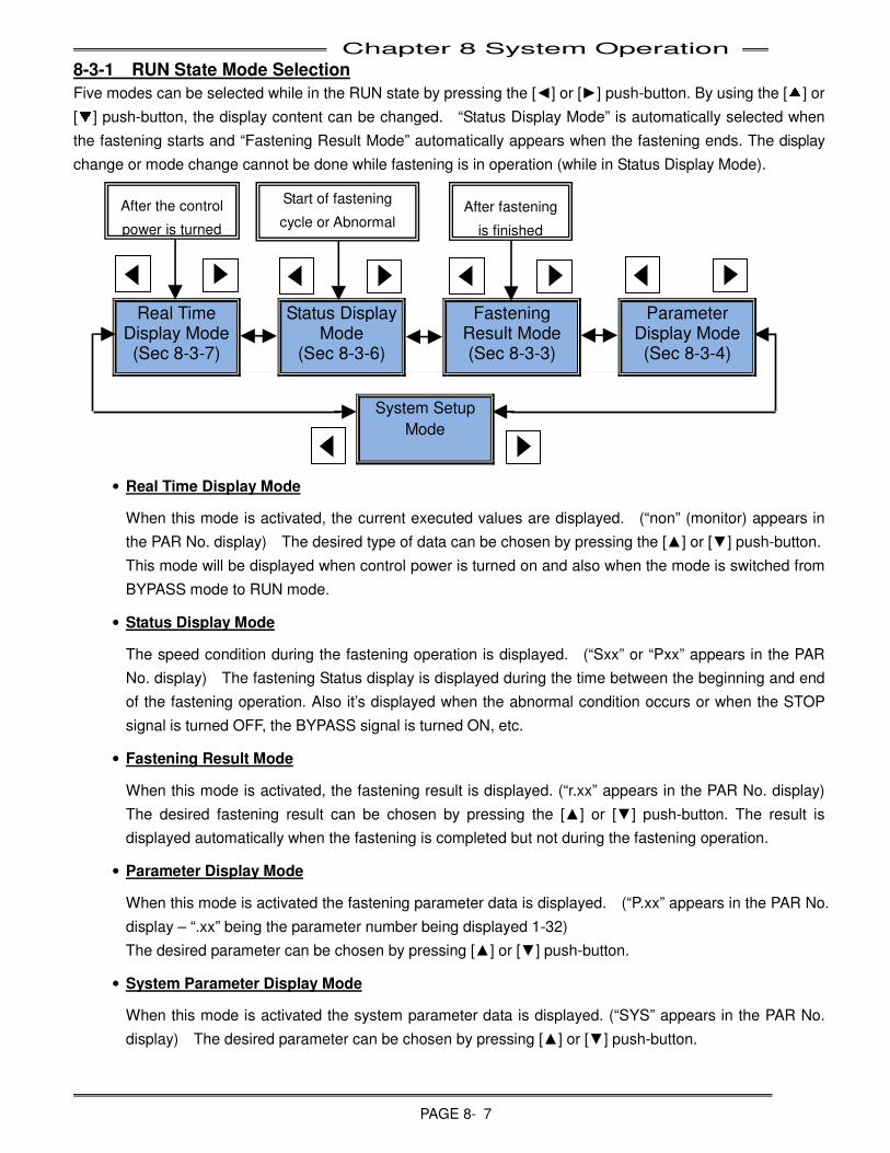
Chapter 8 System Operation
PAGE 8- 7
8-3-1 RUN State Mode Selection
Five modes can be selected while in the RUN state by pressing the [◄] or [►] push-button. By using the [▲] or
[▼] push-button, the display content can be changed. “Status Display Mode” is automatically selected when
the fastening starts and “Fastening Result Mode” automatically appears when the fastening ends. The display
change or mode change cannot be done while fastening is in operation (while in Status Display Mode).
Real Time
Display Mode
(Sec 8-3-7)
Status Display Mode
(Sec 8-3-6)
Fastening Result Mode (Sec 8-3-3)
Parameter Display Mode (Sec 8-3-4)
System Setup
Mode
• Real Time Display Mode
When this mode is activated, the current executed values are displayed. (“non” (monitor) appears in
the PAR No. display) The desired type of data can be chosen by pressing the [▲] or [▼] push-button.
This mode will be displayed when control power is turned on and also when the mode is switched from
BYPASS mode to RUN mode.
• Status Display Mode
The speed condition during the fastening operation is displayed. (“Sxx” or “Pxx” appears in the PAR
No. display) The fastening Status display is displayed during the time between the beginning and end
of the fastening operation. Also it’s displayed when the abnormal condition occurs or when the STOP
signal is turned OFF, the BYPASS signal is turned ON, etc.
• Fastening Result Mode
When this mode is activated, the fastening result is displayed. (“r.xx” appears in the PAR No. display)
The desired fastening result can be chosen by pressing the [▲] or [▼] push-button. The result is
displayed automatically when the fastening is completed but not during the fastening operation.
• Parameter Display Mode
When this mode is activated the fastening parameter data is displayed. (“P.xx” appears in the PAR No.
display – “.xx” being the parameter number being displayed 1-32)
The desired parameter can be chosen by pressing [▲] or [▼] push-button.
• System Parameter Display Mode
When this mode is activated the system parameter data is displayed. (“SYS” appears in the PAR No.
display) The desired parameter can be chosen by pressing [▲] or [▼] push-button.
After the control
power is turned
Start of fastening
cycle or Abnormal After fastening
is finished
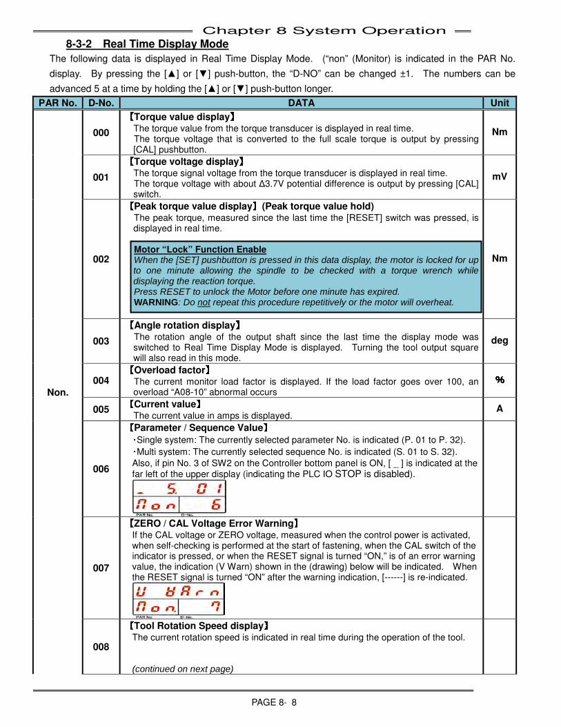
Chapter 8 System Operation
PAGE 8- 8
8-3-2 Real Time Display Mode
The following data is displayed in Real Time Display Mode. (“non” (Monitor) is indicated in the PAR No.
display. By pressing the [▲] or [▼] push-button, the “D-NO” can be changed ±1. The numbers can be
advanced 5 at a time by holding the [▲] or [▼] push-button longer.
PAR No. D-No. DATA Unit
Non.
000
【
【【
【Torque value display】】】
】 The torque value from the torque transducer is displayed in real time. The torque voltage that is converted to the full scale torque is output by pressing [CAL] pushbutton.
Nm
001
【
【【
【Torque voltage display】】】
】 The torque signal voltage from the torque transducer is displayed in real time. The torque voltage with about Δ3.7V potential difference is output by pressing [CAL] switch.
mV
002
【
【【
【Peak torque value display】】】
】(Peak torque value hold) The peak torque, measured since the last time the [RESET] switch was pressed, is displayed in real time. Motor “Lock” Function Enable When the [SET] pushbutton is pressed in this data display, the motor is locked for up to one minute allowing the spindle to be checked with a torque wrench while displaying the reaction torque. Press RESET to unlock the Motor before one minute has expired. WARNING: Do not repeat this procedure repetitively or the motor will overheat.
Nm
003
【
【【
【Angle rotation display】】】
】 The rotation angle of the output shaft since the last time the display mode was switched to Real Time Display Mode is displayed. Turning the tool output square will also read in this mode.
deg
004 【
【【
【Overload factor】】】
】 The current monitor load factor is displayed. If the load factor goes over 100, an overload “A08-10” abnormal occurs
%
%%
%
005 【
【【
【Current value】】】
】 The current value in amps is displayed.
A
006
【
【【
【Parameter / Sequence Value】】】
】
・Single system: The currently selected parameter No. is indicated (P. 01 to P. 32).
・Multi system: The currently selected sequence No. is indicated (S. 01 to S. 32).
Also, if pin No. 3 of SW2 on the Controller bottom panel is ON, [ _ ] is indicated at the far left of the upper display (indicating the PLC IO STOP is disabled).
007
【
【【
【ZERO / CAL Voltage Error Warning】】】
】 If the CAL voltage or ZERO voltage, measured when the control power is activated, when self-checking is performed at the start of fastening, when the CAL switch of the indicator is pressed, or when the RESET signal is turned “ON,” is of an error warning value, the indication (V Warn) shown in the (drawing) below will be indicated. When the RESET signal is turned “ON” after the warning indication, [------] is re-indicated.
008
【
【【
【Tool Rotation Speed display】】】
】 The current rotation speed is indicated in real time during the operation of the tool. (continued on next page)
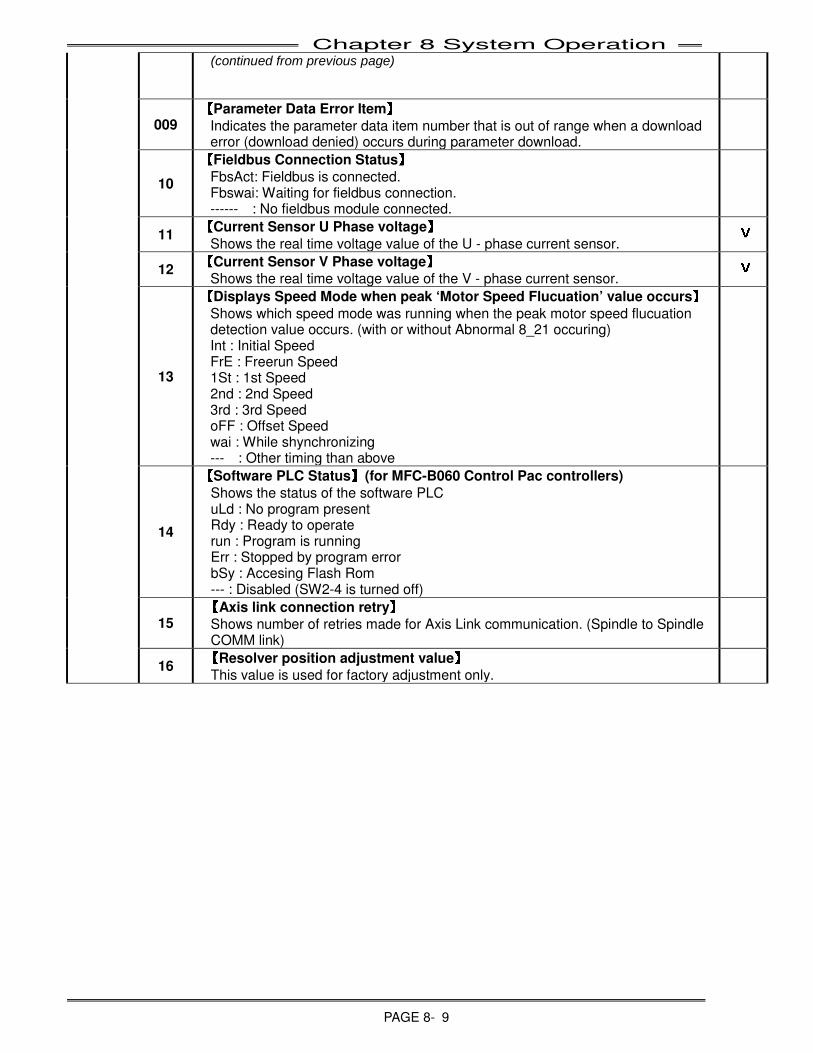
Chapter 8 System Operation
PAGE 8- 9
(continued from previous page)
009 【
【【
【Parameter Data Error Item】
】】
】
Indicates the parameter data item number that is out of range when a download error (download denied) occurs during parameter download.
10
【
【【
【Fieldbus Connection Status】】】
】
FbsAct: Fieldbus is connected. Fbswai: Waiting for fieldbus connection. ------ : No fieldbus module connected.
11
【
【【
【Current Sensor U Phase voltage】】】
】
Shows the real time voltage value of the U - phase current sensor.
V
VV
V
12
【
【【
【Current Sensor V Phase voltage】】】
】
Shows the real time voltage value of the V - phase current sensor. V
VV
V
13
【
【【
【Displays Speed Mode when peak ‘Motor Speed Flucuation’ value occurs】】】
】
Shows which speed mode was running when the peak motor speed flucuation detection value occurs. (with or without Abnormal 8_21 occuring) Int : Initial Speed FrE : Freerun Speed 1St : 1st Speed 2nd : 2nd Speed 3rd : 3rd Speed oFF : Offset Speed wai : While shynchronizing --- : Other timing than above
14
【
【【
【Software PLC Status】】】
】(for MFC-B060 Control Pac controllers)
Shows the status of the software PLC uLd : No program present Rdy : Ready to operate run : Program is running Err : Stopped by program error bSy : Accesing Flash Rom --- : Disabled (SW2-4 is turned off)
15 【
【【
【Axis link connection retry】】】
】
Shows number of retries made for Axis Link communication. (Spindle to Spindle COMM link)
16
【
【【
【Resolver position adjustment value】】】
】
This value is used for factory adjustment only.
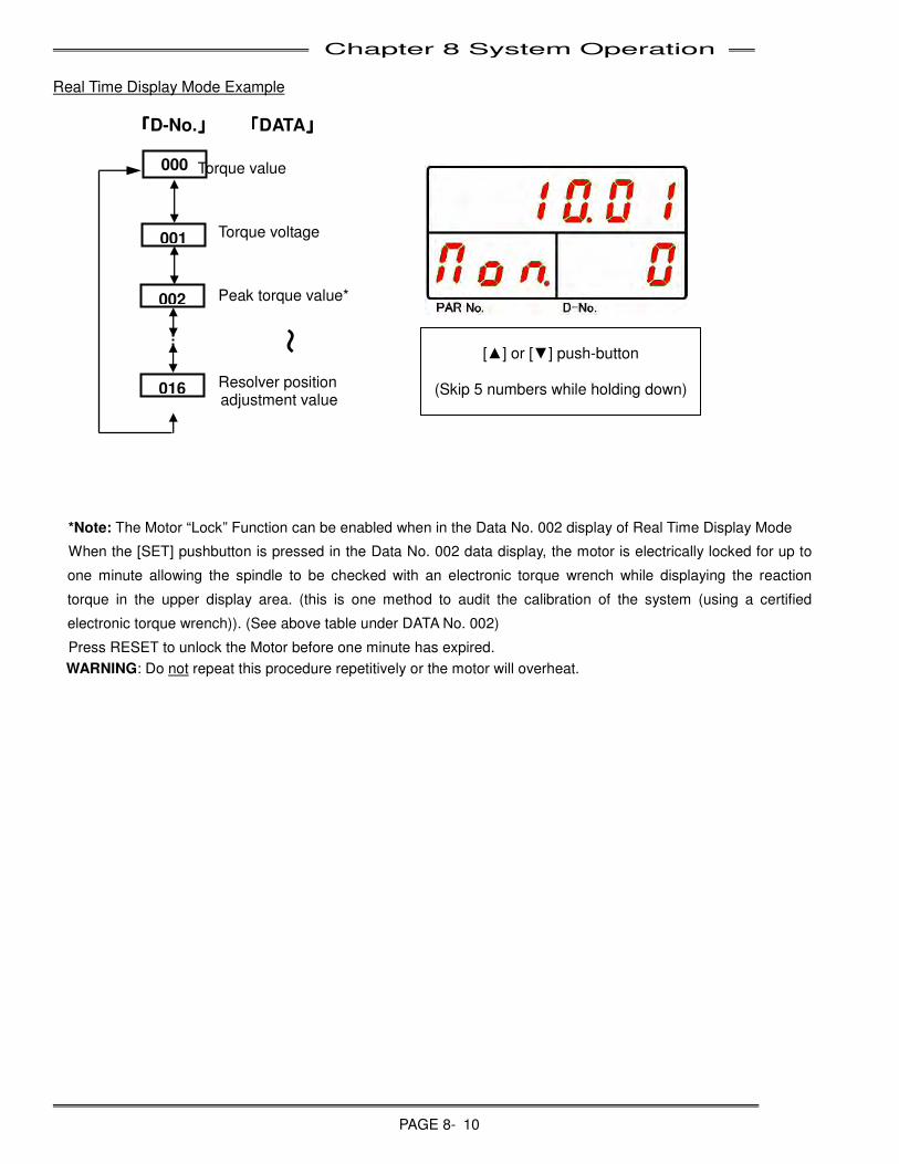
Chapter 8 System Operation
PAGE 8- 10
Real Time Display Mode Example
「「「「D-No.」」」」 「「「「DATA」」」」
Torque value
Torque voltage
Peak torque value*
Resolver position
adjustment value
*Note: The Motor “Lock” Function can be enabled when in the Data No. 002 display of Real Time Display Mode
When the [SET] pushbutton is pressed in the Data No. 002 data display, the motor is electrically locked for up to
one minute allowing the spindle to be checked with an electronic torque wrench while displaying the reaction
torque in the upper display area. (this is one method to audit the calibration of the system (using a certified
electronic torque wrench)). (See above table under DATA No. 002)
Press RESET to unlock the Motor before one minute has expired.
WARNING: Do not repeat this procedure repetitively or the motor will overheat.
~ [▲] or [▼] push-button
(Skip 5 numbers while holding down)
000
001
002
016
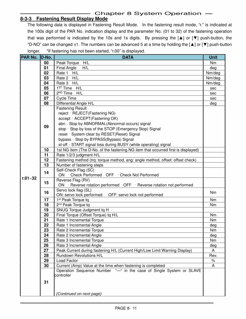
Chapter 8 System Operation
PAGE 8- 11
8-3-3 Fastening Result Display Mode
The following data is displayed in Fastening Result Mode. In the fastening result mode, “r.” is indicated at
the 100s digit of the PAR No. indication display and the parameter No. (01 to 32) of the fastening operation
that was performed is indicated by the 10s and 1s digits. By pressing the [▲] or [▼] push-button, the
“D-NO” can be changed ±1. The numbers can be advanced 5 at a time by holding the [▲] or [▼] push-button
longer. *If fastening has not been started, “r.00” is displayed.
PAR No. D-No. DATA Unit
r.01~32
00 Peak Torque H/L Nm
01 Final Angle H/L deg
02 Rate 1 H/L Nm/deg
03 Rate 2 H/L Nm/deg
04 Rate 3 H/L Nm/deg
05 1ST Time H/L sec
06 2ND Time H/L sec
07 Cycle Time sec
08 Differential Angle H/L deg
09
Fastening Result
reject:REJECT(Fastening NG)
accept:ACCEPT(Fastening OK)
abn:Stop by ABNORMAL(Abnormal occurs) signal
stop:Stop by loss of the STOP (Emergency Stop) Signal
reset:System clear by RESET(Reset) Signal
bypass:Stop by BYPASS(Bypass) Signal
st-off:START signal loss during BUSY (while operating) signal
10 1st NG item (The D-No. of the fastening NG item that occurred first is displayed)
11 Rate 1/2/3 judgment H/L
12 Fastening method (trq: torque method, ang: angle method, offset: offset check)
13 Number of fastening steps
14 Self-Check Flag (SC)
ON :Check Performed OFF :Check Not Performed
15 Reverse Flag (RV)
ON :Reverse rotation performed OFF :Reverse rotation not performed
16 Servo lock flag (SL) ON: servo lock performed OFF: servo lock not performed
Nm
17 1st Peak Torque tq Nm
18 2nd Peak Torque tq Nm
19 SNUG Torque Judgment tq H
20 Final Torque (Offset Torque) tq H/L Nm
21 Rate 1 Incremental Torque Nm
22 Rate 1 Incremental Angle deg
23 Rate 2 Incremental Torque Nm
24 Rate 2 Incremental Angle deg
25 Rate 3 Incremental Torque Nm
26 Rate 3 Incremental Angle deg
27 Peak Current during fastening H/L (Current High/Low Limit Warning Display) A
28 Rundown Revolutions H/L Rev.
29 Load Factor %
30 Current (Amp) Value at the time when fastening is completed A
31
Operation Sequence Number “—“ in the case of Single System or SLAVE controller (Continued on next page)
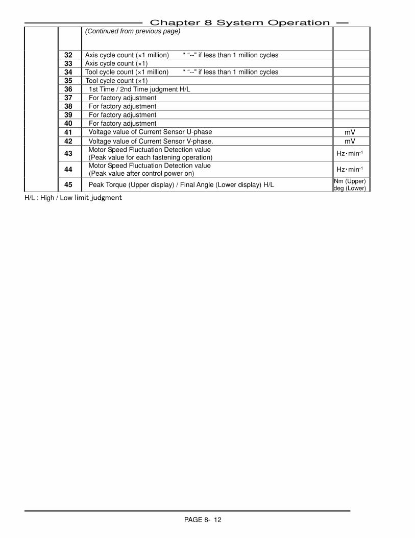
Chapter 8 System Operation
PAGE 8- 12
(Continued from previous page)
32 Axis cycle count (×1 million) * “--" if less than 1 million cycles
33 Axis cycle count (×1)
34 Tool cycle count (×1 million) * “--" if less than 1 million cycles
35 Tool cycle count (×1) 36 1st Time / 2nd Time judgment H/L 37 For factory adjustment 38 For factory adjustment 39 For factory adjustment 40 For factory adjustment
41 Voltage value of Current Sensor U-phase mV
42 Voltage value of Current Sensor V-phase. mV
43 Motor Speed Fluctuation Detection value (Peak value for each fastening operation)
Hz・min-1
44 Motor Speed Fluctuation Detection value (Peak value after control power on)
Hz・min-1
45 Peak Torque (Upper display) / Final Angle (Lower display) H/L Nm (Upper) deg (Lower)
H/L : High / Low limit judgment
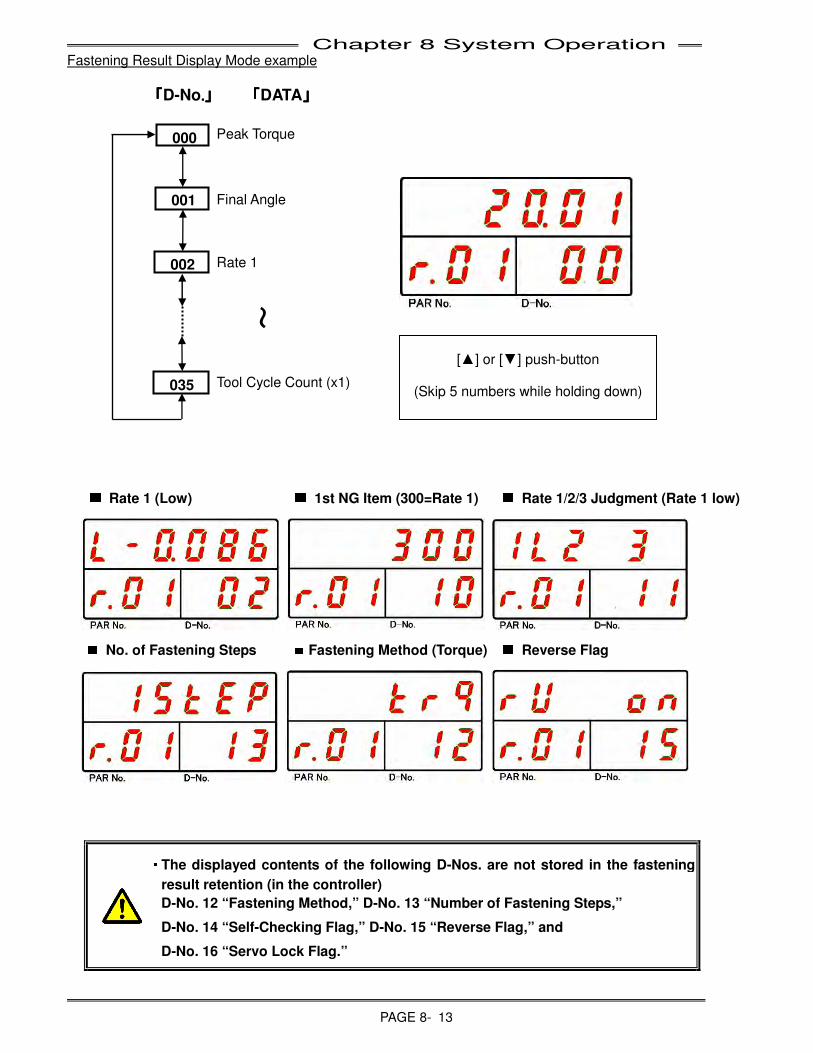
Chapter 8 System Operation
PAGE 8- 13
Fastening Result Display Mode example
「「「「D-No....」」」」 「「「「DATA」」」」
Peak Torque
Final Angle
Rate 1
Tool Cycle Count (x1)
■
■■
■
Rate 1 (Low) ■
■■
■
1st NG Item (300=Rate 1) ■
■■
■
Rate 1/2/3 Judgment (Rate 1 low)
■
■■
■
No. of Fastening Steps ■
■■
■
Fastening Method (Torque) ■
■■
■
Reverse Flag
・
・・
・ The displayed contents of the following D-Nos. are not stored in the fastening
result retention (in the controller)
D-No. 12 “Fastening Method,” D-No. 13 “Number of Fastening Steps,”
D-No. 14 “Self-Checking Flag,” D-No. 15 “Reverse Flag,” and
D-No. 16 “Servo Lock Flag.”
~
[▲] or [▼] push-button
(Skip 5 numbers while holding down)
000
001
002
035
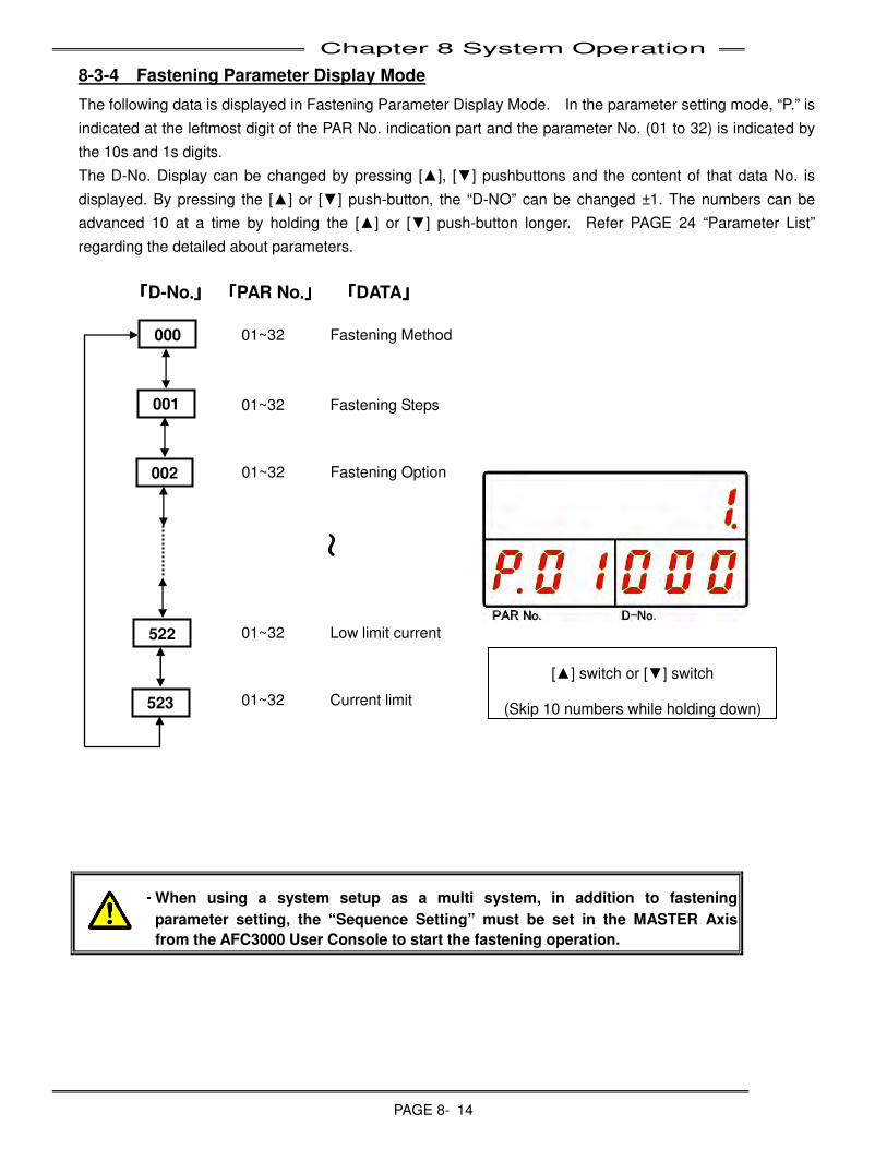
Chapter 8 System Operation
PAGE 8- 14
8-3-4 Fastening Parameter Display Mode
The following data is displayed in Fastening Parameter Display Mode. In the parameter setting mode, “P.” is
indicated at the leftmost digit of the PAR No. indication part and the parameter No. (01 to 32) is indicated by
the 10s and 1s digits.
The D-No. Display can be changed by pressing [▲], [▼] pushbuttons and the content of that data No. is
displayed. By pressing the [▲] or [▼] push-button, the “D-NO” can be changed ±1. The numbers can be
advanced 10 at a time by holding the [▲] or [▼] push-button longer. Refer PAGE 24 “Parameter List”
regarding the detailed about parameters.
「「「「D-No....」」」」 「「「「PAR No....」」」」 「「「「DATA」」」」
01~32 Fastening Method
01~32 Fastening Steps
01~32 Fastening Option
01~32 Low limit current
01~32 Current limit
・
・・
・ When using a system setup as a multi system, in addition to fastening
parameter setting, the “Sequence Setting” must be set in the MASTER Axis
from the AFC3000 User Console to start the fastening operation.
[▲] switch or [▼] switch
(Skip 10 numbers while holding down)
~
000
001
002
522
523
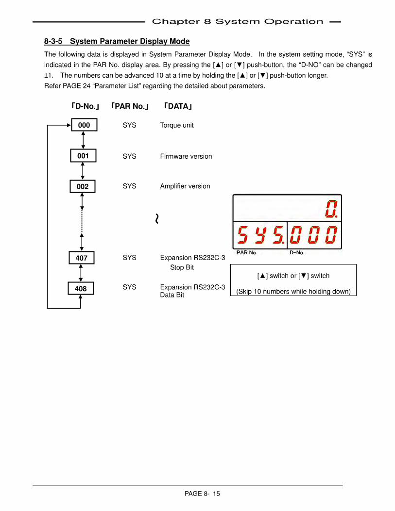
Chapter 8 System Operation
PAGE 8- 15
8-3-5 System Parameter Display Mode
The following data is displayed in System Parameter Display Mode. In the system setting mode, “SYS” is
indicated in the PAR No. display area. By pressing the [▲] or [▼] push-button, the “D-NO” can be changed
±1. The numbers can be advanced 10 at a time by holding the [▲] or [▼] push-button longer.
Refer PAGE 24 “Parameter List” regarding the detailed about parameters.
「「「「D-No....」」」」 「「「「PAR No....」」」」 「「「「DATA」」」」
SYS Torque unit
SYS Firmware version
SYS Amplifier version
SYS Expansion RS232C-3
Stop Bit
SYS Expansion RS232C-3 Data Bit
[▲] switch or [▼] switch
(Skip 10 numbers while holding down)
~
000
001
002
407
408
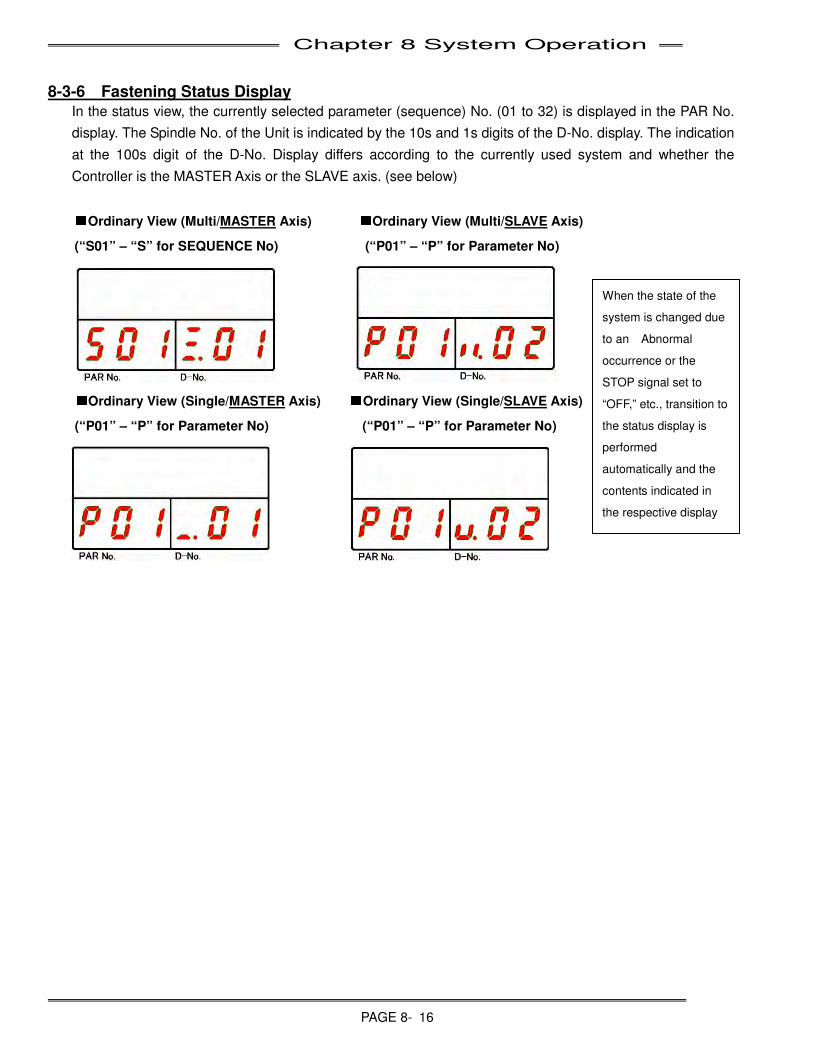
Chapter 8 System Operation
PAGE 8- 16
When the state of the
system is changed due
to an Abnormal
occurrence or the
STOP signal set to
“OFF,” etc., transition to
the status display is
performed
automatically and the
contents indicated in
the respective display
areas change
8-3-6 Fastening Status Display
In the status view, the currently selected parameter (sequence) No. (01 to 32) is displayed in the PAR No.
display. The Spindle No. of the Unit is indicated by the 10s and 1s digits of the D-No. display. The indication
at the 100s digit of the D-No. Display differs according to the currently used system and whether the
Controller is the MASTER Axis or the SLAVE axis. (see below)
■
■■
■Ordinary View (Multi/MASTER Axis)
■
■■
■Ordinary View (Multi/SLAVE Axis)
(“S01” – “S” for SEQUENCE No) (“P01” – “P” for Parameter No)
■
■■
■Ordinary View (Single/MASTER Axis) ■
■■
■Ordinary View (Single/SLAVE Axis)
(“P01” – “P” for Parameter No) (“P01” – “P” for Parameter No)
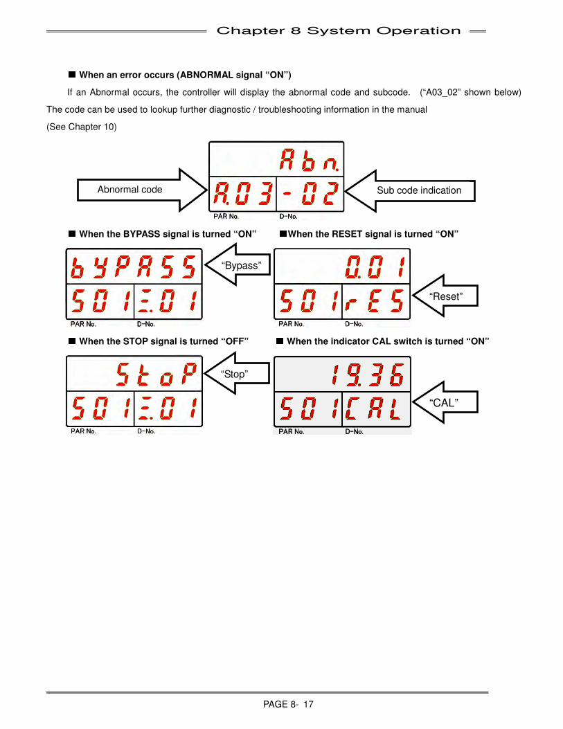
Chapter 8 System Operation
PAGE 8- 17
■
■■
■ When an error occurs (ABNORMAL signal “ON”)
If an Abnormal occurs, the controller will display the abnormal code and subcode. (“A03_02” shown below)
The code can be used to lookup further diagnostic / troubleshooting information in the manual
(See Chapter 10)
■
■■
■ When the BYPASS signal is turned “ON” ■
■■
■When the RESET signal is turned “ON”
■
■■
■ When the STOP signal is turned “OFF” ■
■■
■ When the indicator CAL switch is turned “ON”
Sub code indication Abnormal code
“Bypass”
“Stop”
“Reset”
“CAL”
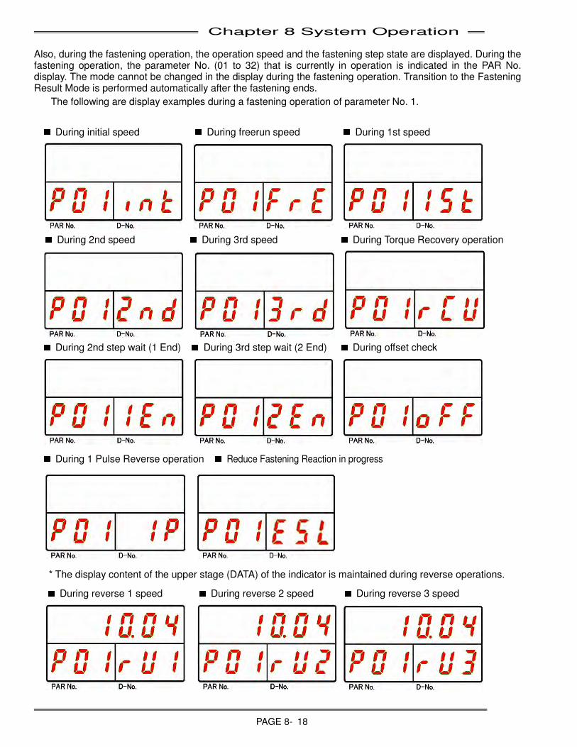
Chapter 8 System Operation
PAGE 8- 18
Also, during the fastening operation, the operation speed and the fastening step state are displayed. During the fastening operation, the parameter No. (01 to 32) that is currently in operation is indicated in the PAR No. display. The mode cannot be changed in the display during the fastening operation. Transition to the Fastening Result Mode is performed automatically after the fastening ends.
The following are display examples during a fastening operation of parameter No. 1.
■
■■
■
During initial speed ■■■
■
During freerun speed ■■■
■
During 1st speed
■
■■
■
During 2nd speed ■■■
■
During 3rd speed ■
■■
■
During Torque Recovery operation
■
■■
■
During 2nd step wait (1 End) ■■■
■
During 3rd step wait (2 End) ■
■■
■
During offset check
■
■■
■
During 1 Pulse Reverse operation ■■■
■
Reduce Fastening Reaction in progress
* The display content of the upper stage (DATA) of the indicator is maintained during reverse operations.
■
■■
■
During reverse 1 speed ■
■■
■
During reverse 2 speed ■■■
■
During reverse 3 speed
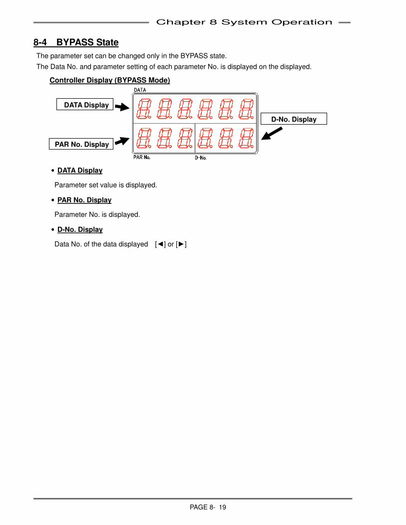
Chapter 8 System Operation
PAGE 8- 19
8-4 BYPASS State
The parameter set can be changed only in the BYPASS state.
The Data No. and parameter setting of each parameter No. is displayed on the displayed.
Controller Display (BYPASS Mode)
• DATA Display
Parameter set value is displayed.
• PAR No. Display
Parameter No. is displayed.
• D-No. Display
Data No. of the data displayed [◄] or [►]
DATA Display
PAR No. Display
D-No. Display
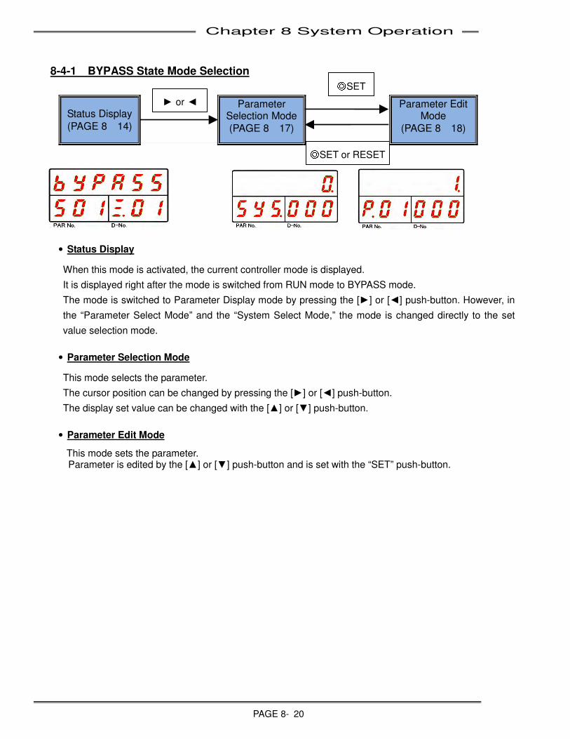
Chapter 8 System Operation
PAGE 8- 20
8-4-1 BYPASS State Mode Selection
Status Display
(PAGE 8-14)
Parameter Selection Mode
(PAGE 8-17)
Parameter Edit Mode
(PAGE 8-18)
• Status Display
When this mode is activated, the current controller mode is displayed.
It is displayed right after the mode is switched from RUN mode to BYPASS mode.
The mode is switched to Parameter Display mode by pressing the [►] or [◄] push-button. However, in
the “Parameter Select Mode” and the “System Select Mode,” the mode is changed directly to the set
value selection mode.
• Parameter Selection Mode
This mode selects the parameter.
The cursor position can be changed by pressing the [►] or [◄] push-button.
The display set value can be changed with the [▲] or [▼] push-button.
• Parameter Edit Mode
This mode sets the parameter. Parameter is edited by the [▲] or [▼] push-button and is set with the “SET” push-button.
► or ◄
◎SET or RESET
◎SET
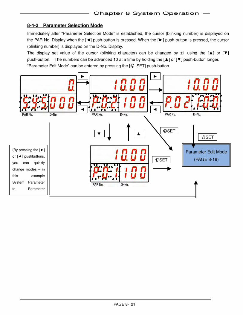
Chapter 8 System Operation
PAGE 8- 21
8-4-2 Parameter Selection Mode
Immediately after “Parameter Selection Mode” is established, the cursor (blinking number) is displayed on
the PAR No. Display when the [◄] push-button is pressed. When the [►] push-button is pressed, the cursor
(blinking number) is displayed on the D-No. Display.
The display set value of the cursor (blinking character) can be changed by ±1 using the [▲] or [▼]
push-button. The numbers can be advanced 10 at a time by holding the [▲] or [▼] push-button longer.
“Parameter Edit Mode” can be entered by pressing the [◎ SET] push-button.
Parameter Edit Mode
(PAGE 8-18)
►
◄
▲ ▼ ◎SET
◎SET
◎SET
►
◄
(By pressing the [►]
or [◄] pushbuttons,
you can quickly
change modes – in
this example
System Parameter
to Parameter
Select)
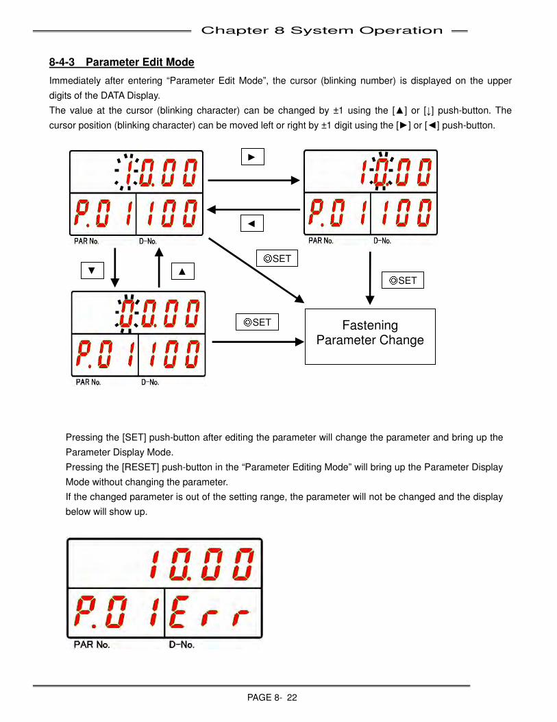
Chapter 8 System Operation
PAGE 8- 22
8-4-3 Parameter Edit Mode
Immediately after entering “Parameter Edit Mode”, the cursor (blinking number) is displayed on the upper
digits of the DATA Display.
The value at the cursor (blinking character) can be changed by ±1 using the [▲] or [↓] push-button. The
cursor position (blinking character) can be moved left or right by ±1 digit using the [►] or [◄] push-button.
Pressing the [SET] push-button after editing the parameter will change the parameter and bring up the
Parameter Display Mode.
Pressing the [RESET] push-button in the “Parameter Editing Mode” will bring up the Parameter Display
Mode without changing the parameter.
If the changed parameter is out of the setting range, the parameter will not be changed and the display
below will show up.
►
◄
▲ ▼
Fastening Parameter Change
◎SET
◎SET
◎SET
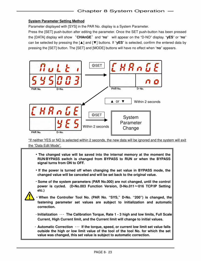
Chapter 8 System Operation
PAGE 8- 23
System Parameter Setting Method
Parameter displayed with [SYS] in the PAR No. display is a System Parameter.
Press the [SET] push-button after editing the parameter. Once the SET push-button has been pressed
the [DATA] display will show “CHAnGE”and “no” will appear on the “D-NO” display. “yES” or “no”
can be selected by pressing the [▲] and [▼] buttons. If “yES” is selected, confirm the entered data by
pressing the [SET] button. The [SET] and [MODE] buttons will have no effect when “no” appears.
*If neither YES or NO is selected within 2 seconds, the new data will be ignored and the system will exit
the “Data Edit Mode”.
・・・・The changed value will be saved into the internal memory at the moment the
RUN/BYPASS switch is changed from BYPASS to RUN or when the BYPASS signal turns from ON to OFF.
・・・・If the power is turned off when changing the set value in BYPASS mode, the
changed value will be canceled and will be set back to the original value.
・
・・
・Some of the system parameters (PAR No.000) are not changed, until the control
power is cycled. (D-No.003 Function Version, D-No.011~~~
~016 TCP/IP Setting
etc.)
・
・・
・When the Controller Tool No. (PAR No. “SYS,” D-No. “200”) is changed, the
fastening parameter set values are subject to initialization and automatic
correction.
・
・・
・ Initialization ・・・・・・・・・
・・・ The Calibration Torque, Rate 1 - 3 high and low limits, Full Scale
Current, High Current limit, and the Current limit will change to initial values.
・
・・
・ Automatic Correction ・・・・・・・・・
・・・ If the torque, speed, or current low limit set value falls
outside the high or low limit value of the tool of the tool No. for which the set value was changed, this set value is subject to automatic correction.
System Parameter
Change
▲ or ▼
◎SET
◎SET
Within 2 seconds
Within 2 seconds
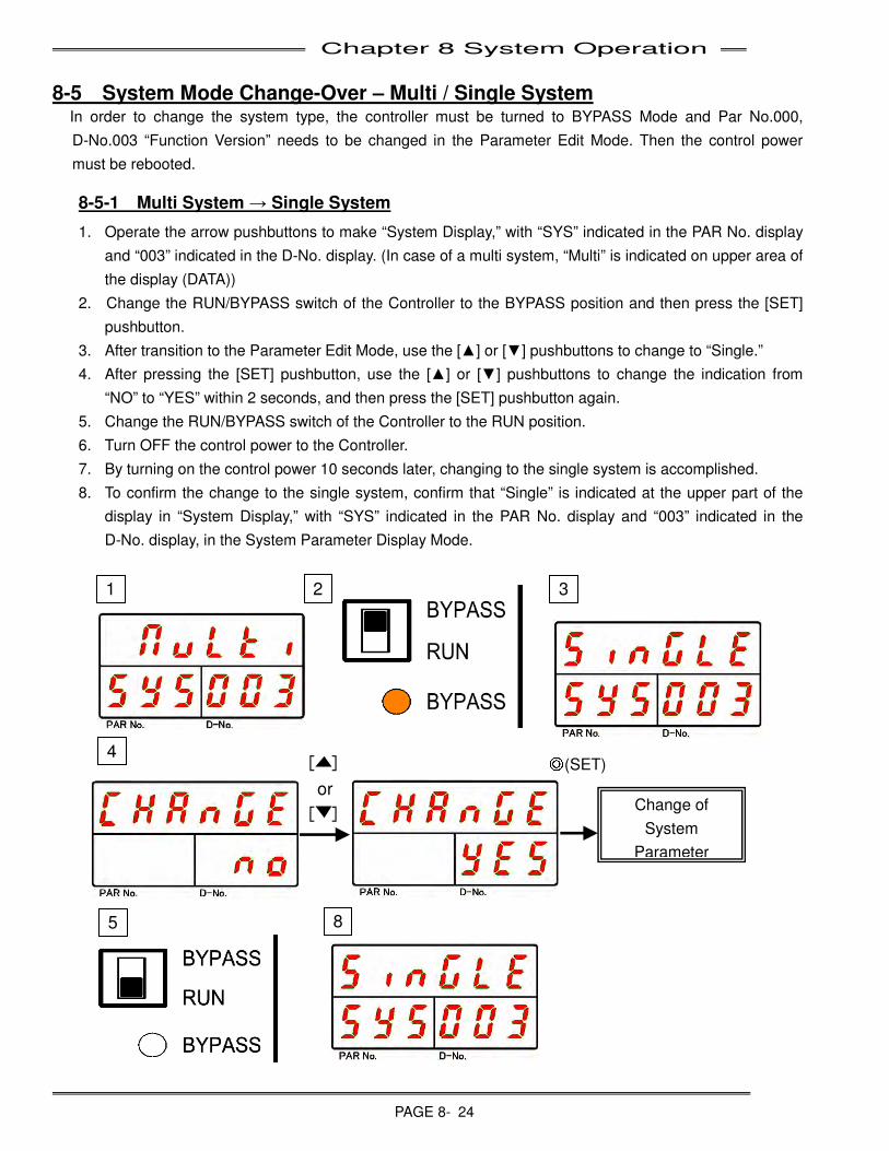
Chapter 8 System Operation
PAGE 8- 24
8-5 System Mode Change-Over – Multi / Single System In order to change the system type, the controller must be turned to BYPASS Mode and Par No.000,
D-No.003 “Function Version” needs to be changed in the Parameter Edit Mode. Then the control power
must be rebooted.
8-5-1 Multi System → Single System
1. Operate the arrow pushbuttons to make “System Display,” with “SYS” indicated in the PAR No. display
and “003” indicated in the D-No. display. (In case of a multi system, “Multi” is indicated on upper area of
the display (DATA))
2. Change the RUN/BYPASS switch of the Controller to the BYPASS position and then press the [SET]
pushbutton.
3. After transition to the Parameter Edit Mode, use the [▲] or [▼] pushbuttons to change to “Single.”
4. After pressing the [SET] pushbutton, use the [▲] or [▼] pushbuttons to change the indication from
“NO” to “YES” within 2 seconds, and then press the [SET] pushbutton again.
5. Change the RUN/BYPASS switch of the Controller to the RUN position.
6. Turn OFF the control power to the Controller.
7. By turning on the control power 10 seconds later, changing to the single system is accomplished.
8. To confirm the change to the single system, confirm that “Single” is indicated at the upper part of the
display in “System Display,” with “SYS” indicated in the PAR No. display and “003” indicated in the
D-No. display, in the System Parameter Display Mode.
[ ]
or
[ ]
8 5
3
4
1
Change of
System
Parameter
◎(SET)
2
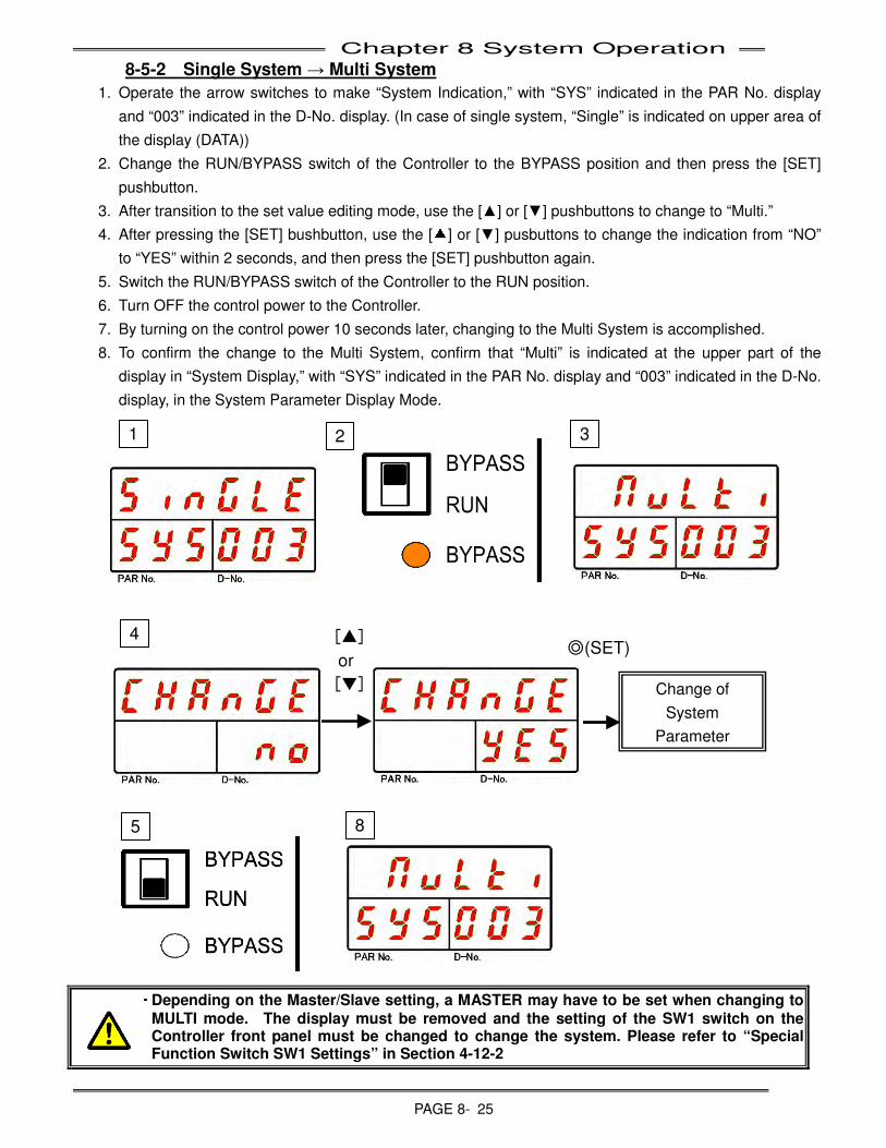
Chapter 8 System Operation
PAGE 8- 25
8-5-2 Single System → Multi System
1. Operate the arrow switches to make “System Indication,” with “SYS” indicated in the PAR No. display
and “003” indicated in the D-No. display. (In case of single system, “Single” is indicated on upper area of
the display (DATA))
2. Change the RUN/BYPASS switch of the Controller to the BYPASS position and then press the [SET]
pushbutton.
3. After transition to the set value editing mode, use the [▲] or [▼] pushbuttons to change to “Multi.”
4. After pressing the [SET] bushbutton, use the [▲] or [▼] pusbuttons to change the indication from “NO”
to “YES” within 2 seconds, and then press the [SET] pushbutton again.
5. Switch the RUN/BYPASS switch of the Controller to the RUN position.
6. Turn OFF the control power to the Controller.
7. By turning on the control power 10 seconds later, changing to the Multi System is accomplished.
8. To confirm the change to the Multi System, confirm that “Multi” is indicated at the upper part of the
display in “System Display,” with “SYS” indicated in the PAR No. display and “003” indicated in the D-No.
display, in the System Parameter Display Mode.
・
・・
・ Depending on the Master/Slave setting, a MASTER may have to be set when changing to
MULTI mode. The display must be removed and the setting of the SW1 switch on the Controller front panel must be changed to change the system. Please refer to “Special Function Switch SW1 Settings” in Section 4-12-2
8 5
3
4
1
Change of
System
Parameter
◎(SET)
2
[▲]
or
[▼]
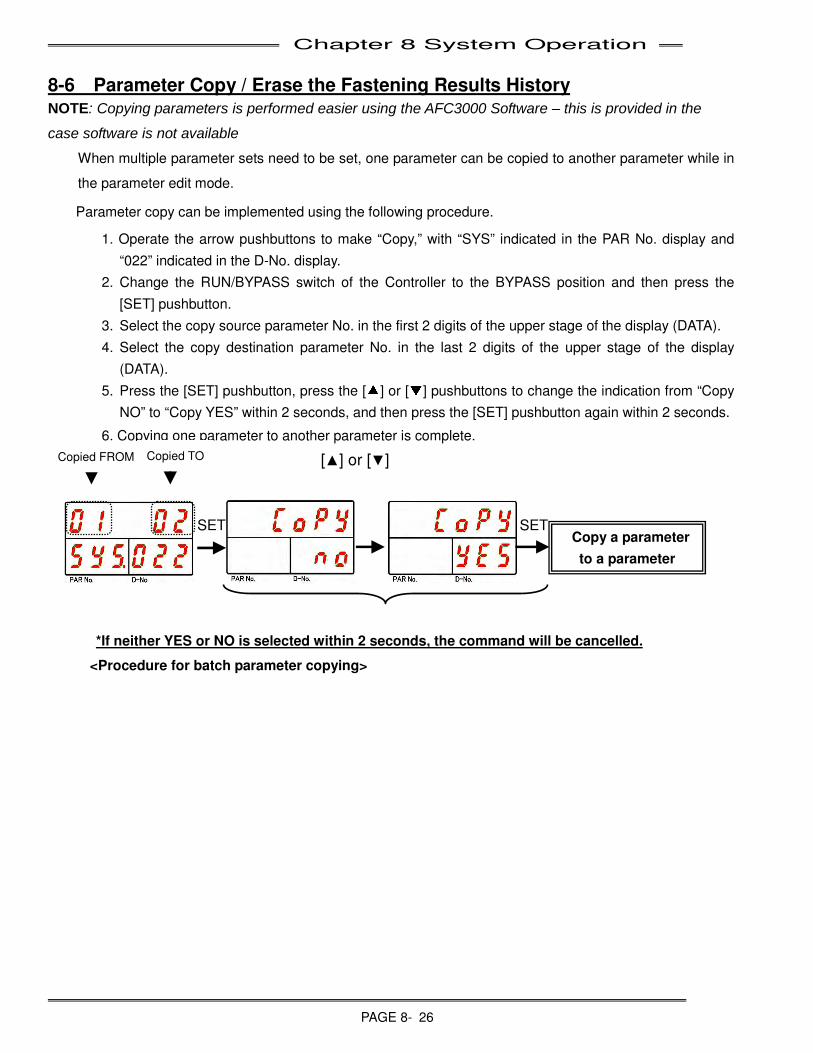
Chapter 8 System Operation
PAGE 8- 26
8-6 Parameter Copy / Erase the Fastening Results History NOTE: Copying parameters is performed easier using the AFC3000 Software – this is provided in the
case software is not available
When multiple parameter sets need to be set, one parameter can be copied to another parameter while in
the parameter edit mode.
Parameter copy can be implemented using the following procedure.
1. Operate the arrow pushbuttons to make “Copy,” with “SYS” indicated in the PAR No. display and
“022” indicated in the D-No. display.
2. Change the RUN/BYPASS switch of the Controller to the BYPASS position and then press the
[SET] pushbutton.
3. Select the copy source parameter No. in the first 2 digits of the upper stage of the display (DATA).
4. Select the copy destination parameter No. in the last 2 digits of the upper stage of the display
(DATA).
5. Press the [SET] pushbutton, press the [▲] or [▼] pushbuttons to change the indication from “Copy
NO” to “Copy YES” within 2 seconds, and then press the [SET] pushbutton again within 2 seconds.
6. Copying one parameter to another parameter is complete.
<Procedure for batch parameter copying>
SET Copy a parameter
to a parameter
SET
[▲] or [▼] Copied FROM Copied TO
*If neither YES or NO is selected within 2 seconds, the command will be cancelled.
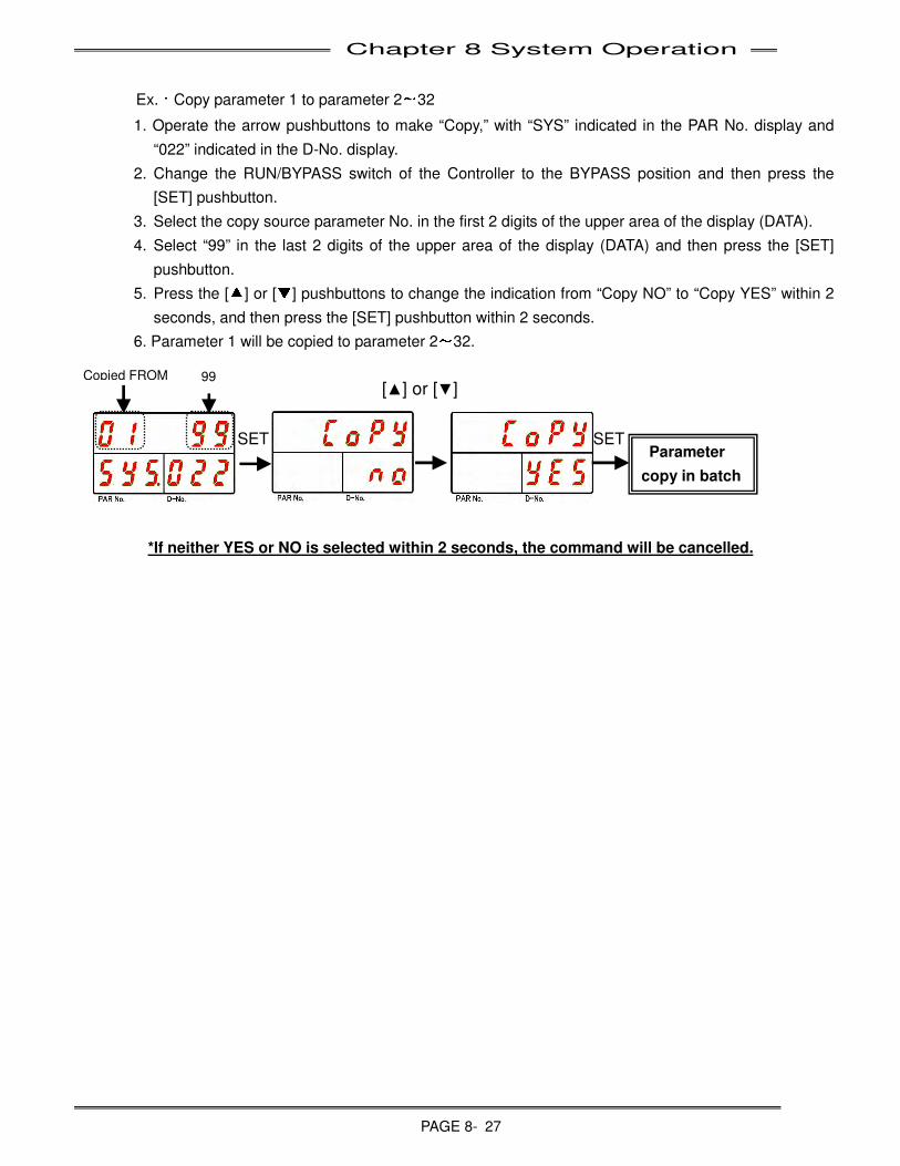
Chapter 8 System Operation
PAGE 8- 27
Ex.:Copy parameter 1 to parameter 2~32
1. Operate the arrow pushbuttons to make “Copy,” with “SYS” indicated in the PAR No. display and
“022” indicated in the D-No. display.
2. Change the RUN/BYPASS switch of the Controller to the BYPASS position and then press the
[SET] pushbutton.
3. Select the copy source parameter No. in the first 2 digits of the upper area of the display (DATA).
4. Select “99” in the last 2 digits of the upper area of the display (DATA) and then press the [SET]
pushbutton.
5. Press the [▲] or [▼] pushbuttons to change the indication from “Copy NO” to “Copy YES” within 2
seconds, and then press the [SET] pushbutton within 2 seconds.
6. Parameter 1 will be copied to parameter 2~32.
SET Parameter
copy in batch
SET
[▲] or [▼] Copied FROM 99
*If neither YES or NO is selected within 2 seconds, the command will be cancelled.
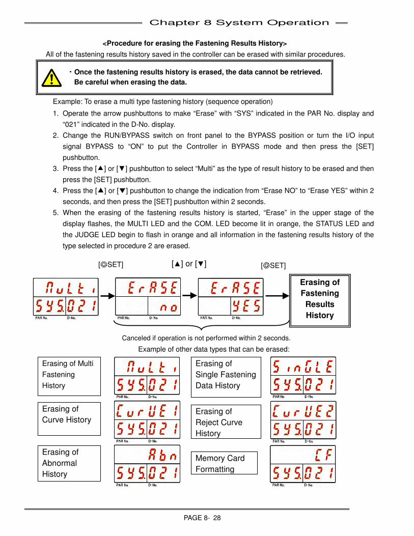
Chapter 8 System Operation
PAGE 8- 28
<Procedure for erasing the Fastening Results History>
All of the fastening results history saved in the controller can be erased with similar procedures.
・
・・
・Once the fastening results history is erased, the data cannot be retrieved.
Be careful when erasing the data.
Example: To erase a multi type fastening history (sequence operation)
1. Operate the arrow pushbuttons to make “Erase” with “SYS” indicated in the PAR No. display and
“021” indicated in the D-No. display.
2. Change the RUN/BYPASS switch on front panel to the BYPASS position or turn the I/O input
signal BYPASS to “ON” to put the Controller in BYPASS mode and then press the [SET]
pushbutton.
3. Press the [▲] or [▼] pushbutton to select “Multi” as the type of result history to be erased and then
press the [SET] pushbutton.
4. Press the [▲] or [▼] pushbutton to change the indication from “Erase NO” to “Erase YES” within 2
seconds, and then press the [SET] pushbutton within 2 seconds.
5. When the erasing of the fastening results history is started, “Erase” in the upper stage of the
display flashes, the MULTI LED and the COM. LED become lit in orange, the STATUS LED and
the JUDGE LED begin to flash in orange and all information in the fastening results history of the
type selected in procedure 2 are erased.
Example of other data types that can be erased:
Erasing of
Fastening
Results
History
Memory Card
Formatting
Erasing of
Single Fastening
Data History
Erasing of
Curve History Erasing of
Reject Curve
History
Erasing of
Abnormal
History
Canceled if operation is not performed within 2 seconds.
Erasing of Multi
Fastening
History
[◎SET] [▲] or [▼] [◎SET]
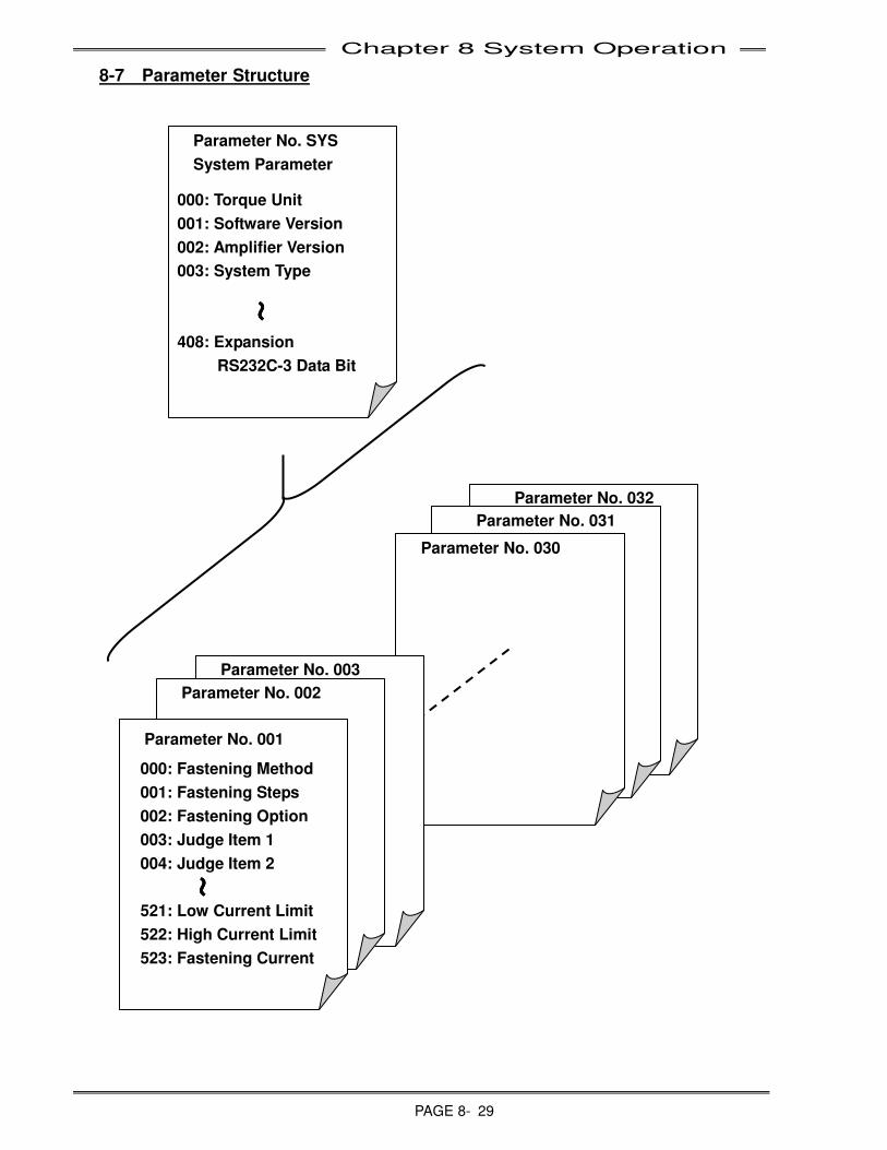
Chapter 8 System Operation
PAGE 8- 29
8-7 Parameter Structure
Parameter No. 032
Parameter No. 031
Parameter No. 030
Parameter No. 003
Parameter No. 002
Parameter No. 001
000: Fastening Method
001: Fastening Steps
002: Fastening Option
003: Judge Item 1
004: Judge Item 2
521: Low Current Limit
522: High Current Limit
523: Fastening Current
~~ ~~
Parameter No. SYS
System Parameter
000: Torque Unit
001: Software Version
002: Amplifier Version
003: System Type
408: Expansion
RS232C-3 Data Bit
~~ ~~
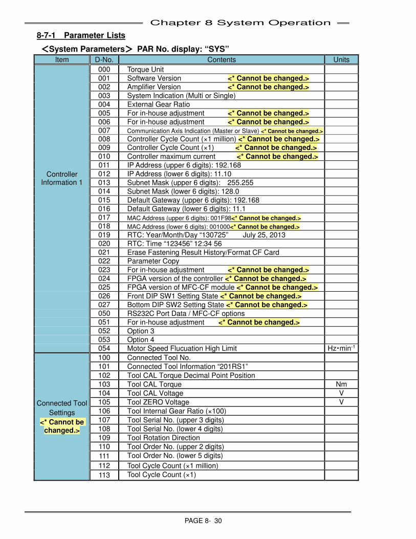
Chapter 8 System Operation
PAGE 8- 30
8-7-1 Parameter Lists
<<<<System Parameters>>>> PAR No. display: “SYS”
Item D-No. Contents Units
Controller Information 1
000 Torque Unit
001 Software Version <* Cannot be changed.>
002 Amplifier Version <* Cannot be changed.>
003 System Indication (Multi or Single)
004 External Gear Ratio
005 For in-house adjustment <* Cannot be changed.>
006 For in-house adjustment <* Cannot be changed.>
007 Communication Axis Indication (Master or Slave) <* Cannot be changed.>
008 Controller Cycle Count (×1 million) <* Cannot be changed.>
009 Controller Cycle Count (×1) <* Cannot be changed.>
010 Controller maximum current <* Cannot be changed.>
011 IP Address (upper 6 digits): 192.168
012 IP Address (lower 6 digits): 11.10
013 Subnet Mask (upper 6 digits): 255.255
014 Subnet Mask (lower 6 digits): 128.0
015 Default Gateway (upper 6 digits): 192.168
016 Default Gateway (lower 6 digits): 11.1
017 MAC Address (upper 6 digits): 001F98<* Cannot be changed.>
018 MAC Address (lower 6 digits): 001000<* Cannot be changed.>
019 RTC: Year/Month/Day “130725” July 25, 2013
020 RTC: Time “123456” 12:34 56
021 Erase Fastening Result History/Format CF Card
022 Parameter Copy
023 For in-house adjustment <* Cannot be changed.>
024 FPGA version of the controller <* Cannot be changed.>
025 FPGA version of MFC-CF module <* Cannot be changed.>
026 Front DIP SW1 Setting State <* Cannot be changed.>
027 Bottom DIP SW2 Setting State <* Cannot be changed.>
050 RS232C Port Data / MFC-CF options
051 For in-house adjustment <* Cannot be changed.>
052 Option 3
053 Option 4
054 Motor Speed Flucuation High Limit Hz・min-1
Connected Tool
Settings
<* Cannot be changed.>
100 Connected Tool No.
101 Connected Tool Information “201RS1”
102 Tool CAL Torque Decimal Point Position
103 Tool CAL Torque Nm
104 Tool CAL Voltage V
105 Tool ZERO Voltage V
106 Tool Internal Gear Ratio (×100)
107 Tool Serial No. (upper 3 digits)
108 Tool Serial No. (lower 4 digits)
109 Tool Rotation Direction
110 Tool Order No. (upper 2 digits)
111 Tool Order No. (lower 5 digits)
112 Tool Cycle Count (×1 million)
113 Tool Cycle Count (×1)
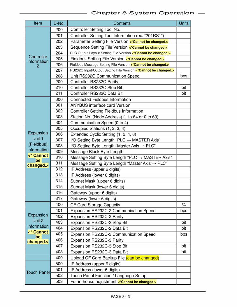
Chapter 8 System Operation
PAGE 8- 31
Item D-No. Contents Units
Controller Information
2
200 Controller Setting Tool No.
201 Controller Setting Tool Information (ex. “201RS1”)
202 Parameter Setting File Version <*Cannot be changed.>
203 Sequence Setting File Version <*Cannot be changed.>
204 PLC Output Layout Setting File Version <*Cannot be changed.>
205 Fieldbus Setting File Version <*Cannot be changed.>
206 Fieldbus Message Setting File Version <*Cannot be changed.>
207 RS232C Input/Output Setting File Version <*Cannot be changed.>
208 Unit RS232C Communication Speed bps
209 Controller RS232C Parity
210 Controller RS232C Stop Bit bit
211 Controller RS232C Data Bit bit
Expansion
Unit 1
(Fieldbus)
Information
<* Cannot be
changed.>
300 Connected Fieldbus Information
301 ANYBUS interface card Version
302 Controller Setting Fieldbus Information
303 Station No. (Node Address) (1 to 64 or 0 to 63)
304 Communication Speed (0 to 4)
305 Occupied Stations (1, 2, 3, 4)
306 Extended Cyclic Setting (1, 2, 4, 8)
307 I/O Setting Byte Length “PLC → MASTER Axis”
308 I/O Setting Byte Length “Master Axis → PLC”
309 Message Block Byte Length
310 Message Setting Byte Length “PLC → MASTER Axis”
311 Message Setting Byte Length “Master Axis → PLC”
312 IP Address (upper 6 digits)
313 IP Address (lower 6 digits)
314 Subnet Mask (upper 6 digits)
315 Subnet Mask (lower 6 digits)
316 Gateway (upper 6 digits)
317 Gateway (lower 6 digits)
Expansion
Unit 2
Information
<* Cannot be
changed.>
400 CF Card Storage Capacity %
401 Expansion RS232C-2 Communication Speed bps
402 Expansion RS232C-2 Parity
403 Expansion RS232C-2 Stop Bit bit
404 Expansion RS232C-2 Data Bit bit
405 Expansion RS232C-3 Communication Speed bps
406 Expansion RS232C-3 Parity
407 Expansion RS232C-3 Stop Bit bit
408 Expansion RS232C-3 Data Bit bit
409 Upload CF Card Backup File (can be changed)
Touch Panel
500 IP Address (upper 6 digits)
501 IP Address (lower 6 digits)
502 Touch Panel Function / Language Setup
503 For in-house adjustment <*Cannot be changed.>
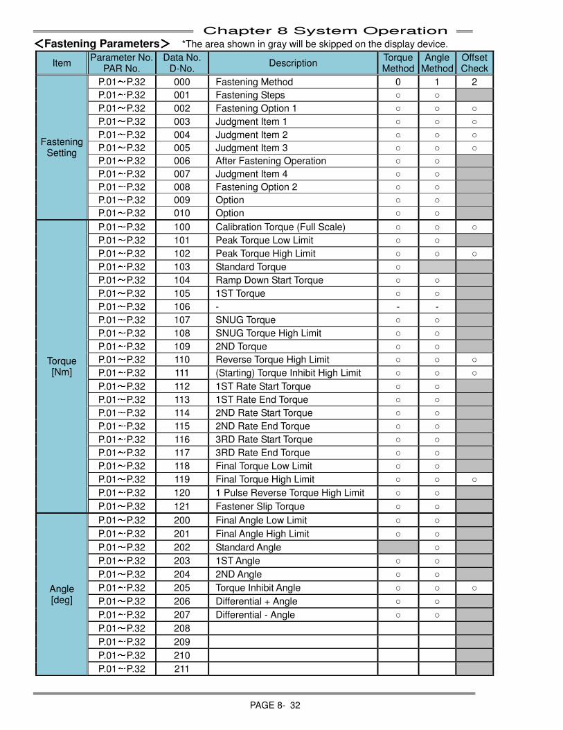
Chapter 8 System Operation
PAGE 8- 32
<<<<Fastening Parameters>>>> *The area shown in gray will be skipped on the display device.
Item Parameter No.
PAR No. Data No.
D-No. Description
Torque Method
Angle Method
Offset Check
Fastening Setting
P.01~P.32 000 Fastening Method 0 1 2
P.01~P.32 001 Fastening Steps ○ ○
P.01~P.32 002 Fastening Option 1 ○ ○ ○
P.01~P.32 003 Judgment Item 1 ○ ○ ○
P.01~P.32 004 Judgment Item 2 ○ ○ ○
P.01~P.32 005 Judgment Item 3 ○ ○ ○
P.01~P.32 006 After Fastening Operation ○ ○
P.01~P.32 007 Judgment Item 4 ○ ○
P.01~P.32 008 Fastening Option 2 ○ ○
P.01~P.32 009 Option ○ ○
P.01~P.32 010 Option ○ ○
Torque [Nm]
P.01~P.32 100 Calibration Torque (Full Scale) ○ ○ ○
P.01~P.32 101 Peak Torque Low Limit ○ ○
P.01~P.32 102 Peak Torque High Limit ○ ○ ○
P.01~P.32 103 Standard Torque ○
P.01~P.32 104 Ramp Down Start Torque ○ ○
P.01~P.32 105 1ST Torque ○ ○
P.01~P.32 106 - - -
P.01~P.32 107 SNUG Torque ○ ○
P.01~P.32 108 SNUG Torque High Limit ○ ○
P.01~P.32 109 2ND Torque ○ ○
P.01~P.32 110 Reverse Torque High Limit ○ ○ ○
P.01~P.32 111 (Starting) Torque Inhibit High Limit ○ ○ ○
P.01~P.32 112 1ST Rate Start Torque ○ ○
P.01~P.32 113 1ST Rate End Torque ○ ○
P.01~P.32 114 2ND Rate Start Torque ○ ○
P.01~P.32 115 2ND Rate End Torque ○ ○
P.01~P.32 116 3RD Rate Start Torque ○ ○
P.01~P.32 117 3RD Rate End Torque ○ ○
P.01~P.32 118 Final Torque Low Limit ○ ○
P.01~P.32 119 Final Torque High Limit ○ ○ ○
P.01~P.32 120 1 Pulse Reverse Torque High Limit ○ ○
P.01~P.32 121 Fastener Slip Torque ○ ○
Angle [deg]
P.01~P.32 200 Final Angle Low Limit ○ ○
P.01~P.32 201 Final Angle High Limit ○ ○
P.01~P.32 202 Standard Angle ○
P.01~P.32 203 1ST Angle ○ ○
P.01~P.32 204 2ND Angle ○ ○
P.01~P.32 205 Torque Inhibit Angle ○ ○ ○
P.01~P.32 206 Differential + Angle ○ ○
P.01~P.32 207 Differential - Angle ○ ○
P.01~P.32 208
P.01~P.32 209
P.01~P.32 210
P.01~P.32 211
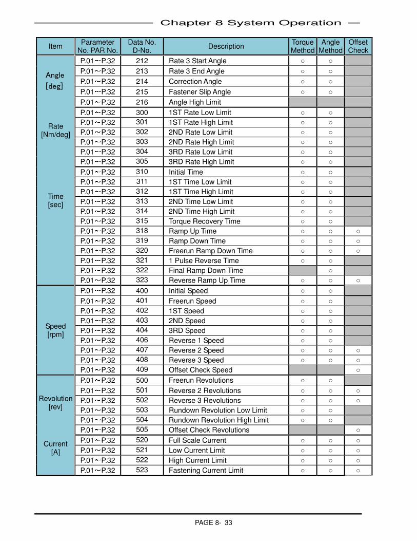
Chapter 8 System Operation
PAGE 8- 33
Item Parameter
No. PAR No. Data No.
D-No. Description
Torque Method
Angle Method
Offset Check
Rate [Nm/deg]
Time [sec]
P.01~P.32 212 Rate 3 Start Angle ○ ○
P.01~P.32 213 Rate 3 End Angle ○ ○
P.01~P.32 214 Correction Angle ○ ○
P.01~P.32 215 Fastener Slip Angle ○ ○
P.01~P.32 216 Angle High Limit
P.01~P.32 300 1ST Rate Low Limit ○ ○
P.01~P.32 301 1ST Rate High Limit ○ ○
P.01~P.32 302 2ND Rate Low Limit ○ ○
P.01~P.32 303 2ND Rate High Limit ○ ○
P.01~P.32 304 3RD Rate Low Limit ○ ○
P.01~P.32 305 3RD Rate High Limit ○ ○
P.01~P.32 310 Initial Time ○ ○
P.01~P.32 311 1ST Time Low Limit ○ ○
P.01~P.32 312 1ST Time High Limit ○ ○
P.01~P.32 313 2ND Time Low Limit ○ ○
P.01~P.32 314 2ND Time High Limit ○ ○
P.01~P.32 315 Torque Recovery Time ○ ○
P.01~P.32 318 Ramp Up Time ○ ○ ○
P.01~P.32 319 Ramp Down Time ○ ○ ○
P.01~P.32 320 Freerun Ramp Down Time ○ ○ ○
P.01~P.32 321 1 Pulse Reverse Time ○ ○
P.01~P.32 322 Final Ramp Down Time ○
P.01~P.32 323 Reverse Ramp Up Time ○ ○ ○
Speed [rpm]
P.01~P.32 400 Initial Speed ○ ○
P.01~P.32 401 Freerun Speed ○ ○
P.01~P.32 402 1ST Speed ○ ○
P.01~P.32 403 2ND Speed ○ ○
P.01~P.32 404 3RD Speed ○ ○
P.01~P.32 406 Reverse 1 Speed ○ ○
P.01~P.32 407 Reverse 2 Speed ○ ○ ○
P.01~P.32 408 Reverse 3 Speed ○ ○ ○
P.01~P.32 409 Offset Check Speed ○
Revolution [rev]
Current [A]
P.01~P.32 500 Freerun Revolutions ○ ○
P.01~P.32 501 Reverse 2 Revolutions ○ ○ ○
P.01~P.32 502 Reverse 3 Revolutions ○ ○ ○
P.01~P.32 503 Rundown Revolution Low Limit ○ ○
P.01~P.32 504 Rundown Revolution High Limit ○ ○
P.01~P.32 505 Offset Check Revolutions ○
P.01~P.32 520 Full Scale Current ○ ○ ○
P.01~P.32 521 Low Current Limit ○ ○ ○
P.01~P.32 522 High Current Limit ○ ○ ○
P.01~P.32 523 Fastening Current Limit ○ ○ ○
Angle
[deg]
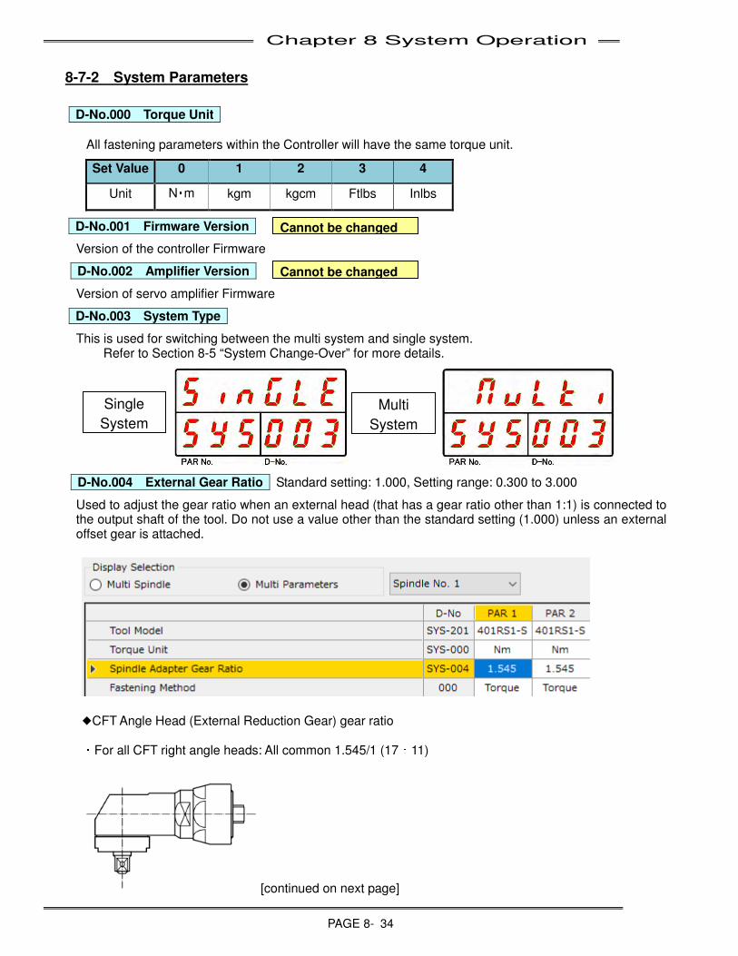
Chapter 8 System Operation
PAGE 8- 34
8-7-2 System Parameters
D-No.000
Torque Unit
All fastening parameters within the Controller will have the same torque unit.
Set Value 0 1 2 3 4
Unit N・m kgm kgcm Ftlbs Inlbs
D-No.001
Firmware Version
Version of the controller Firmware
D-No.002
Amplifier Version
Version of servo amplifier Firmware
D-No.003
System Type
This is used for switching between the multi system and single system. Refer to Section 8-5 “System Change-Over” for more details.
D-No.004
External Gear Ratio Standard setting: 1.000, Setting range: 0.300 to 3.000
Used to adjust the gear ratio when an external head (that has a gear ratio other than 1:1) is connected to the output shaft of the tool. Do not use a value other than the standard setting (1.000) unless an external offset gear is attached.
◆CFT Angle Head (External Reduction Gear) gear ratio
・For all CFT right angle heads: All common 1.545/1 (17:11)
[continued on next page]
Cannot be changed
Cannot be changed
Single
System
Multi
System
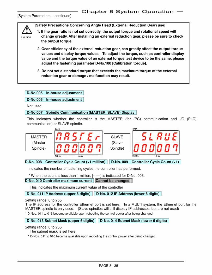
Chapter 8 System Operation
PAGE 8- 35
[System Parameters – continued]
[Safety Precautions Concerning Angle Head (External Reduction Gear) use]
1. If the gear ratio is not set correctly, the output torque and rotational speed will
change greatly. After installing an external reduction gear, please be sure to check
the output torque.
2. Gear efficiency of the external reduction gear, can greatly affect the output torque
values and display torque values. To adjust the torque, such as controller display
value and the torque value of an external torque test device to be the same, please
adjust the fastening parameter D-No.100 [Calibration torque].
3. Do not set a standard torque that exceeds the maximum torque of the external
reduction gear or damage / malfunction may result.
D-No.005
In-house adjustment
D-No.006
In-house adjustment
Not used.
D-No.007
Spindle Communication (MASTER, SLAVE) Display
This indicates whether the controller is the MASTER (for (PC) communication and I/O (PLC)
communication) or SLAVE spindle.
D-No. 008 Controller Cycle Count (×1 million) D-No. 009 Controller Cycle Count (×1)
Indicates the number of fastening cycles the controller has performed.
* When the count is less than 1 million, [------] is indicated for D-No. 008.
D-No. 010 Controller maximum current Cannot be changed.
This indicates the maximum current value of the controller
D-No. 011 IP Address (upper 6 digits) D-No. 012 IP Address (lower 6 digits)
Setting range: 0 to 255 The IP address for the controller Ethernet port is set here. In a MULTI system, the Ethernet port for the MASTER spindle is only used. (Slave spindles will still display IP addresses, but are not used)
* D-Nos. 011 to 016 become available upon rebooting the control power after being changed.
D-No. 013 Subnet Mask (upper 6 digits) D-No. 014 Subnet Mask (lower 6 digits)
Setting range: 0 to 255 The subnet mask is set here.
* D-Nos. 011 to 016 become available upon rebooting the control power after being changed.
MASTER
(Master
Spindle)
SLAVE
(Slave
Spindle)
Caution
Chapter 8 System Operation
PAGE 8- 36
[System Parameters – continued]
D-No. 015 Default Gateway (upper 6 digits) Setting range: 0 to 255
D-No. 016 Default Gateway (lower 6 digits) Setting range: 0 to 255
The default gateway is set here.
* D-Nos. 011 to 016 become available upon rebooting the control power after being changed.
D-No. 017 MAC Address (upper 6 digits) Cannot be changed.
D-No. 018 MAC Address (lower 6 digits) Cannot be changed.
The MAC ID address of the Ethernet port is indicated.
D-No. 019 RTC: Year/Month/Day Setting range: 13 to 99 (year), 1 to 12 (month), 1 to 31 (day)
D-No. 020 RTC: Time Setting range: 0 to 23 (hours), 0 to 59 (minutes), 0 to 59 (seconds)
The date and time of the real time clock (RTC) are indicated. The range for the year is 2013 to 2099.
* This is not indicated at a SLAVE spindle in a MULTI system.
D-No. 021 Erase Fastening Result History/Format CF Card
Erasing of the fastening results history can be executed. Please refer to “Copying of Parameters and Erasing of the Fastening Result History” in Section 8-6 regarding the method for erasing the fastening results history. Also, if the Expansion Unit 2 (Model: MFC-CF, MFC-CFEN) is installed, formatting of the CF card can be executed. Please refer to “Formatting the Memory Card” regarding the method for formatting the CF card.
D-No. 022 Parameter Copy
Copying of parameters is performed. Please refer to “Copying of Parameters and Erasing of the Fastening Result History” on Section 8-6 regarding the method for copying parameters.
D-No. 023 For in-house adjustment
Not used.
D-No. 024 FPGA Version of controller
This indicates the FPGA (Field Programmable Gate Array) version number of controller.
D-No. 025 FPGA version of MFC-CF module
This indicates the FPGA (Field Programmable Gate Array) version number of MFC-CF module.
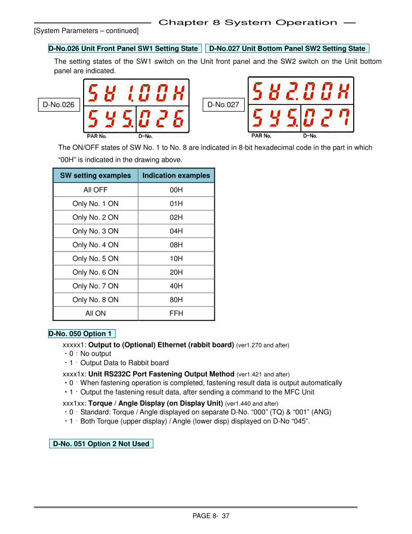
Chapter 8 System Operation
PAGE 8- 37
[System Parameters – continued]
D-No.026 Unit Front Panel SW1 Setting State D-No.027 Unit Bottom Panel SW2 Setting State
The setting states of the SW1 switch on the Unit front panel and the SW2 switch on the Unit bottom
panel are indicated.
The ON/OFF states of SW No. 1 to No. 8 are indicated in 8-bit hexadecimal code in the part in which
“00H” is indicated in the drawing above.
SW setting examples Indication examples
All OFF 00H
Only No. 1 ON 01H
Only No. 2 ON 02H
Only No. 3 ON 04H
Only No. 4 ON 08H
Only No. 5 ON 10H
Only No. 6 ON 20H
Only No. 7 ON 40H
Only No. 8 ON 80H
All ON FFH
D-No. 050 Option 1
xxxxx1: Output to (Optional) Ethernet (rabbit board) (ver1.270 and after)
・0:No output
・1:Output Data to Rabbit board
xxxx1x: Unit RS232C Port Fastening Output Method (ver1.421 and after)
・0:When fastening operation is completed, fastening result data is output automatically
・1:Output the fastening result data, after sending a command to the MFC Unit
xxx1xx: Torque / Angle Display (on Display Unit) (ver1.440 and after)
・0:Standard: Torque / Angle displayed on separate D-No. “000” (TQ) & “001” (ANG)
・1:Both Torque (upper display) / Angle (lower disp) displayed on D-No “045”.
D-No. 051 Option 2 Not Used
D-No.026 D-No.027

Chapter 8 System Operation
PAGE 8- 38
D-No. 052 Option 3
xxxxx1: Fieldbus Message update timing (ver1.560 and after)
・0:(Default) Initialize and clear fastening result message at start of fastening sequence
・1:Hold fastening result message until end of sequence operation
(Note: if using firmware 1.559 or earlier, set to “1”)
xxxx1x: Generate RESULT Timing (ver1.560 and after)
・0:After 1st Step (1st Step must be reached) (Default)
・1:After Start signal is turned off
(Note: if using firmware 1.559 or earlier, set to “1”)
xxx1xx: Torque Transducer Preamp Data Reading Size (ver1.580 and after)
・0:128byte (Default) – full data size available
・1:51byte – Only required tool data – (reduce possibility of Abn 3_x caused by corrupt data)
(Also reduces power up time by approx.. 2sec less)
D-No. 053 Option 4
xxxxx1: [ABN3_3] Preamp Monitor Timing (ver1.438 and after)
・0: Yes (Default) – Monitors all the time controller power is on
・1: Yes – Monitors during motor non-running time only and when start signal changes from off to on.
(optimal for high noise installations, long cables and/or Abn3_3 with extension cables)
xxxx1x: [ABN 8_21] Motor Speed Flucuation (Hunting) Detection (ver1.580 and after)
・0:Yes (Default) detection is enabled
・1:No – Disabled detection
(The detection Limit can be set in next D-No. (054))
x1xxxx: Buzzer Output at Sequence Judgment (ver1.560 and after)
・0:Disbled (Default) Buzzer is not output
・1:Enabled – Buzzer output when TOTAL REJECT or TOTAL ACCEPT turns “ON”
1xxxxx: Buzzer Output at Spindle Judgment (ver1.560 and after)
・0:Disbled (Default) Buzzer is not output
・1:Enabled – Buzzer output when REJECT or ACCEPT turns “ON”
D-No. 054 Motor Hunting (Speed Fluctuation) Limit Standard setting:25000, Setting range:0~999999
The high limit of the Motor Hunting (Speed Fluctuation) during fastening operation is set.
If this Motor Speed Fluctuation High Limit is exceeded, abnormal “ABN8-21” fastening judgment is
made.
When "0" is set, the upper limit value will be the same value as the standard setting.
If nusciance abnormals appear due to the torsional energy released in long spindle extensions when
the motor stops rotating, change the setting to “999999” (Before ver. 1.579) or see D-No. 53 (ver. 1.580 or
after) to disable this abnormal check.
Note: At firmware version 1.670, the function was enhanced to only generate an Abnormal (8-21)
during the fastening process (After 1st Torque / Angle detection to Fastening Stop). From Fastening
Start BEFORE 1st Torque / Angle only a Warning is output.
In the case of an abnormal, fastening will stop when the upper limit is detected and ABN8-21 will occur.
In the case of a warning, fastening will continue even if the upper limit is detected.
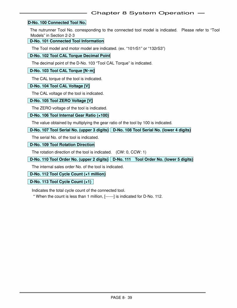
Chapter 8 System Operation
PAGE 8- 39
D-No. 100 Connected Tool No.
The nutrunner Tool No. corresponding to the connected tool model is indicated. Please refer to “Tool
Models” in Section 2-2-3
D-No. 101 Connected Tool Information
The Tool model and motor model are indicated. (ex. “101rS1” or “132rS3”)
D-No. 102 Tool CAL Torque Decimal Point
The decimal point of the D-No. 103 “Tool CAL Torque” is indicated.
D-No. 103 Tool CAL Torque [N・
・・
・m]
The CAL torque of the tool is indicated.
D-No. 104 Tool CAL Voltage [V]
The CAL voltage of the tool is indicated.
D-No. 105 Tool ZERO Voltage [V]
The ZERO voltage of the tool is indicated.
D-No. 106 Tool Internal Gear Ratio (×100)
The value obtained by multiplying the gear ratio of the tool by 100 is indicated.
D-No. 107 Tool Serial No. (upper 3 digits) D-No. 108 Tool Serial No. (lower 4 digits)
The serial No. of the tool is indicated.
D-No. 109 Tool Rotation Direction
The rotation direction of the tool is indicated. (CW: 0, CCW: 1)
D-No. 110 Tool Order No. (upper 2 digits) D-No. 111 Tool Order No. (lower 5 digits)
The internal sales order No. of the tool is indicated.
D-No. 112 Tool Cycle Count (×1 million)
D-No. 113 Tool Cycle Count (×1)
Indicates the total cycle count of the connected tool.
* When the count is less than 1 million, [------] is indicated for D-No. 112.
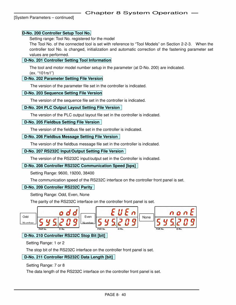
Chapter 8 System Operation
PAGE 8- 40
[System Parameters – continued]
D-No. 200 Controller Setup Tool No.
Setting range: Tool No. registered for the model
The Tool No. of the connected tool is set with reference to “Tool Models” on Section 2-2-3. When the
controller tool No. is changed, initialization and automatic correction of the fastening parameter set
values are performed.
D-No. 201 Controller Setting Tool Information
The tool and motor model number setup in the parameter (at D-No. 200) are indicated.
(ex. “101rs1”)
D-No. 202 Parameter Setting File Version
The version of the parameter file set in the controller is indicated.
D-No. 203 Sequence Setting File Version
The version of the sequence file set in the controller is indicated.
D-No. 204 PLC Output Layout Setting File Version
The version of the PLC output layout file set in the controller is indicated.
D-No. 205 Fieldbus Setting File Version
The version of the fieldbus file set in the controller is indicated.
D-No. 206 Fieldbus Message Setting File Version
The version of the fieldbus message file set in the controller is indicated.
D-No. 207 RS232C Input/Output Setting File Version
The version of the RS232C input/output set in the Controller is indicated.
D-No. 208 Controller RS232C Communication Speed [bps]
Setting Range: 9600, 19200, 38400
The communication speed of the RS232C interface on the controller front panel is set.
D-No. 209 Controller RS232C Parity
Setting Range: Odd, Even, None
The parity of the RS232C interface on the controller front panel is set.
D-No. 210 Controller RS232C Stop Bit [bit]
Setting Range: 1 or 2
The stop bit of the RS232C interface on the controller front panel is set.
D-No. 211 Controller RS232C Data Length [bit]
Setting Range: 7 or 8
The data length of the RS232C interface on the controller front panel is set.
Odd
Number
Even
Number
None
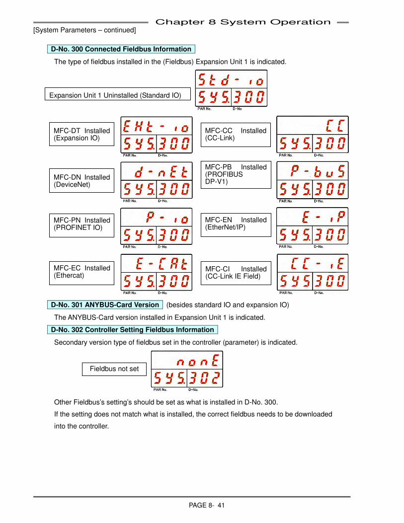
Chapter 8 System Operation
PAGE 8- 41
[System Parameters – continued]
D-No. 300 Connected Fieldbus Information
The type of fieldbus installed in the (Fieldbus) Expansion Unit 1 is indicated.
D-No. 301 ANYBUS-Card Version (besides standard IO and expansion IO)
The ANYBUS-Card version installed in Expansion Unit 1 is indicated.
D-No. 302 Controller Setting Fieldbus Information
Secondary version type of fieldbus set in the controller (parameter) is indicated.
Other Fieldbus’s setting’s should be set as what is installed in D-No. 300.
If the setting does not match what is installed, the correct fieldbus needs to be downloaded
into the controller.
Fieldbus not set
Expansion Unit 1 Uninstalled (Standard IO)
MFC-DT Installed (Expansion IO)
MFC-CC Installed (CC-Link)
MFC-DN Installed (DeviceNet)
MFC-PB Installed (PROFIBUS DP-V1)
MFC-PN Installed (PROFINET IO)
MFC-EN Installed (EtherNet/IP)
MFC-EC Installed (Ethercat)
MFC-CI Installed (CC-Link IE Field)
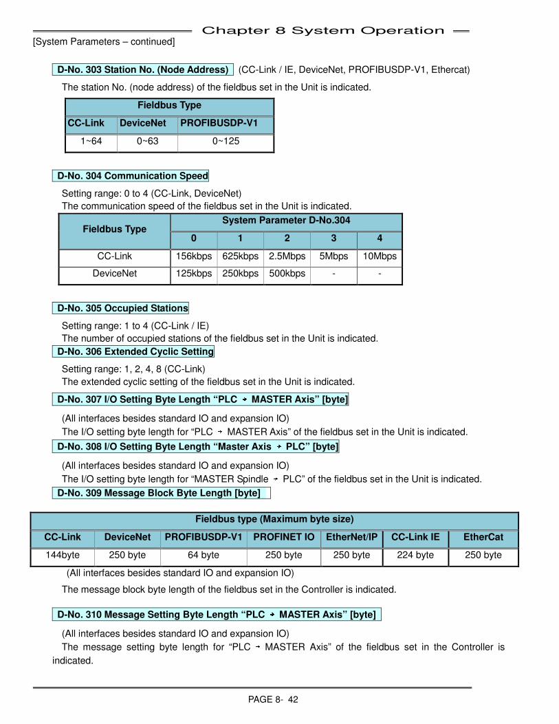
Chapter 8 System Operation
PAGE 8- 42
[System Parameters – continued]
D-No. 303 Station No. (Node Address) (CC-Link / IE, DeviceNet, PROFIBUSDP-V1, Ethercat)
The station No. (node address) of the fieldbus set in the Unit is indicated.
Fieldbus Type
CC-Link DeviceNet PROFIBUSDP-V1
1~64 0~63 0~125
D-No. 304 Communication Speed
Setting range: 0 to 4 (CC-Link, DeviceNet)
The communication speed of the fieldbus set in the Unit is indicated.
Fieldbus Type System Parameter D-No.304
0 1 2 3 4
CC-Link 156kbps 625kbps 2.5Mbps 5Mbps 10Mbps
DeviceNet 125kbps 250kbps 500kbps - -
D-No. 305 Occupied Stations
Setting range: 1 to 4 (CC-Link / IE)
The number of occupied stations of the fieldbus set in the Unit is indicated.
D-No. 306 Extended Cyclic Setting
Setting range: 1, 2, 4, 8 (CC-Link)
The extended cyclic setting of the fieldbus set in the Unit is indicated.
D-No. 307 I/O Setting Byte Length “PLC →→→
→ MASTER Axis” [byte]
(All interfaces besides standard IO and expansion IO)
The I/O setting byte length for “PLC → MASTER Axis” of the fieldbus set in the Unit is indicated.
D-No. 308 I/O Setting Byte Length “Master Axis →→→
→ PLC” [byte]
(All interfaces besides standard IO and expansion IO)
The I/O setting byte length for “MASTER Spindle → PLC” of the fieldbus set in the Unit is indicated.
D-No. 309 Message Block Byte Length [byte]
(All interfaces besides standard IO and expansion IO)
The message block byte length of the fieldbus set in the Controller is indicated.
D-No. 310 Message Setting Byte Length “PLC →→→
→ MASTER Axis” [byte]
(All interfaces besides standard IO and expansion IO)
The message setting byte length for “PLC → MASTER Axis” of the fieldbus set in the Controller is
indicated.
Fieldbus type (Maximum byte size)
CC-Link DeviceNet PROFIBUSDP-V1 PROFINET IO EtherNet/IP CC-Link IE EtherCat
144byte 250 byte 64 byte 250 byte 250 byte 224 byte 250 byte
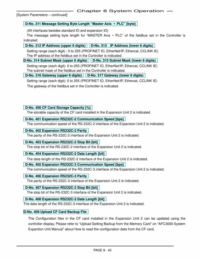
Chapter 8 System Operation
PAGE 8- 43
[System Parameters – continued]
D-No. 311 Message Setting Byte Length “Master Axis →→→
→ PLC” [byte]
(All interfaces besides standard IO and expansion IO)
The message setting byte length for “MASTER Axis → PLC” of the fieldbus set in the Controller is
indicated.
D-No. 312 IP Address (upper 6 digits) D-No. 313 IP Address (lower 6 digits)
Setting range (each digit) : 0 to 255 (PROFINET IO, EtherNet/IP, Ethercat, CCLINK IE)
The IP address of the fieldbus set in the Controller is indicated.
D-No. 314 Subnet Mask (upper 6 digits) D-No. 315 Subnet Mask (lower 6 digits)
Setting range (each digit): 0 to 255 (PROFINET IO, EtherNet/IP, Ethercat, CCLINK IE)
The subnet mask of the fieldbus set in the Controller is indicated.
D-No. 316 Gateway (upper 6 digits) D-No. 317 Gateway (lower 6 digits)
Setting range (each digit): 0 to 255 (PROFINET IO, EtherNet/IP, Ethercat, CCLINK IE)
The gateway of the fieldbus set in the Controller is indicated.
D-No. 400 CF Card Storage Capacity [%]
The storable capacity of the CF card installed in the Expansion Unit 2 is indicated.
D-No. 401 Expansion RS232C-2 Communication Speed [bps]
The communication speed of the RS-232C-2 interface of the Expansion Unit 2 is indicated.
D-No. 402 Expansion RS232C-2 Parity
The parity of the RS-232C-2 interface of the Expansion Unit 2 is indicated.
D-No. 403 Expansion RS232C-2 Stop Bit [bit]
The stop bit of the RS-232C-2 interface of the Expansion Unit 2 is indicated.
D-No. 404 Expansion RS232C-2 Data Length [bit]
The data length of the RS-232C-2 interface of the Expansion Unit 2 is indicated.
D-No. 405 Expansion RS232C-3 Communication Speed [bps]
The communication speed of the RS-232C-3 interface of the Expansion Unit 2 is indicated.
D-No. 406 Expansion RS232C-3 Parity
The parity of the RS-232C-3 interface of the Expansion Unit 2 is indicated.
D-No. 407 Expansion RS232C-3 Stop Bit [bit]
The stop bit of the RS-232C-3 interface of the Expansion Unit 2 is indicated.
D-No. 408 Expansion RS232C-3 Data Length [bit]
The data length of the RS-232C-3 interface of the Expansion Unit 2 is indicated.
D-No. 409 Upload CF Card Backup File
The Configuration files in the CF card installed in the Expansion Unit 2 can be updated using the
controller display. Please refer to “Upload Setting Backup from the Memory Card” on “AFC3000 System
Expantion Unit Manual” about How to read the configuration data from the CF card.
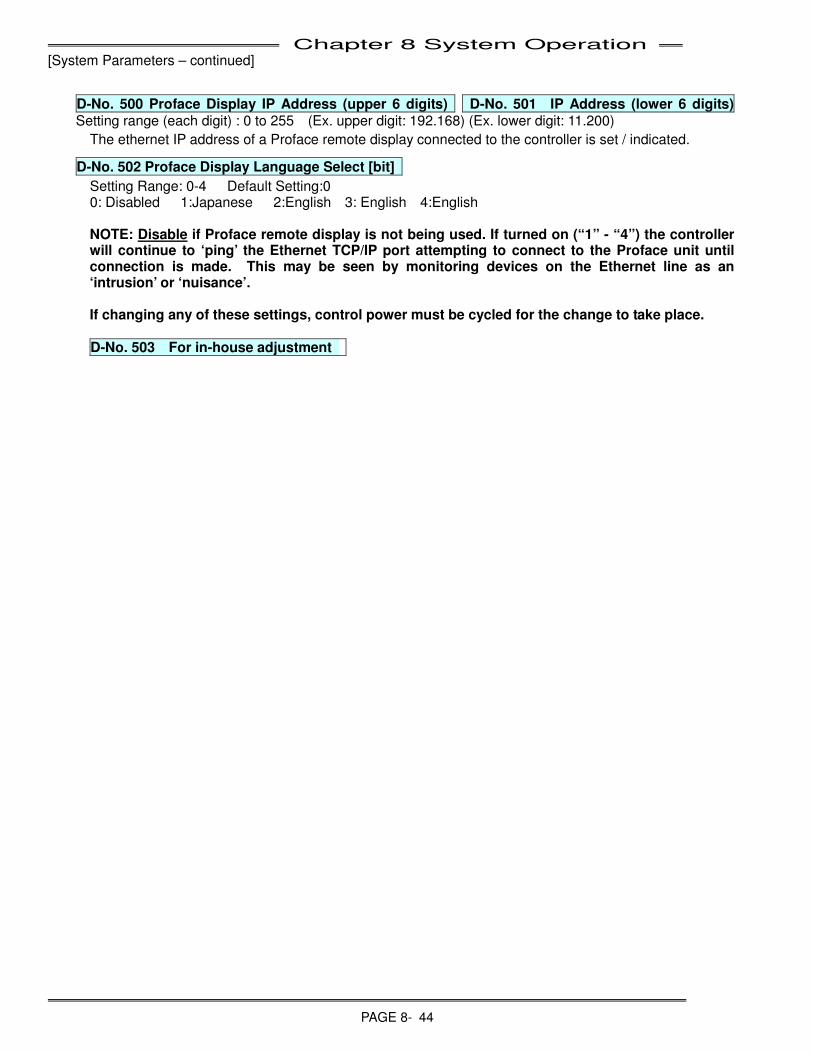
Chapter 8 System Operation
PAGE 8- 44
[System Parameters – continued]
D-No. 500 Proface Display IP Address (upper 6 digits) D-No. 501 IP Address (lower 6 digits) Setting range (each digit) : 0 to 255 (Ex. upper digit: 192.168) (Ex. lower digit: 11.200)
The ethernet IP address of a Proface remote display connected to the controller is set / indicated.
D-No. 502 Proface Display Language Select [bit]
Setting Range: 0-4 Default Setting:0 0: Disabled 1:Japanese 2:English 3: English 4:English
NOTE: Disable if Proface remote display is not being used. If turned on (“1” - “4”) the controller will continue to ‘ping’ the Ethernet TCP/IP port attempting to connect to the Proface unit until connection is made. This may be seen by monitoring devices on the Ethernet line as an ‘intrusion’ or ‘nuisance’. If changing any of these settings, control power must be cycled for the change to take place. D-No. 503 For in-house adjustment
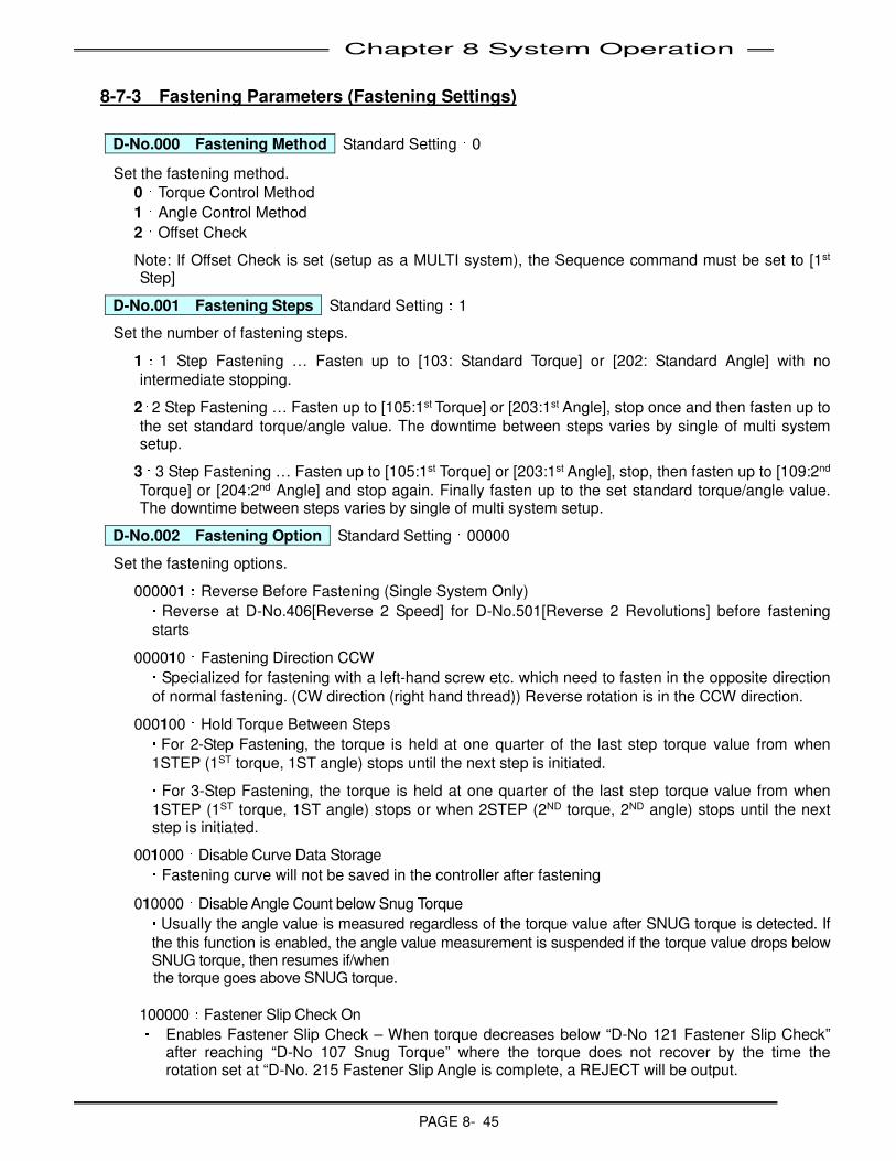
Chapter 8 System Operation
PAGE 8- 45
8-7-3 Fastening Parameters (Fastening Settings)
D-No.000
Fastening Method Standard Setting:0
Set the fastening method.
0:Torque Control Method
1:Angle Control Method
2:Offset Check
Note: If Offset Check is set (setup as a MULTI system), the Sequence command must be set to [1st Step]
D-No.001
Fastening Steps Standard Setting:1
Set the number of fastening steps.
1:1 Step Fastening … Fasten up to [103: Standard Torque] or [202: Standard Angle] with no
intermediate stopping.
2:2 Step Fastening … Fasten up to [105:1st Torque] or [203:1st Angle], stop once and then fasten up to
the set standard torque/angle value. The downtime between steps varies by single of multi system setup.
3:3 Step Fastening … Fasten up to [105:1st Torque] or [203:1st Angle], stop, then fasten up to [109:2nd
Torque] or [204:2nd Angle] and stop again. Finally fasten up to the set standard torque/angle value. The downtime between steps varies by single of multi system setup.
D-No.002
Fastening Option Standard Setting:00000
Set the fastening options.
000001:Reverse Before Fastening (Single System Only)
・Reverse at D-No.406[Reverse 2 Speed] for D-No.501[Reverse 2 Revolutions] before fastening
starts
000010:Fastening Direction CCW
・Specialized for fastening with a left-hand screw etc. which need to fasten in the opposite direction
of normal fastening. (CW direction (right hand thread)) Reverse rotation is in the CCW direction.
000100:Hold Torque Between Steps
・For 2-Step Fastening, the torque is held at one quarter of the last step torque value from when
1STEP (1ST torque, 1ST angle) stops until the next step is initiated.
・For 3-Step Fastening, the torque is held at one quarter of the last step torque value from when
1STEP (1ST torque, 1ST angle) stops or when 2STEP (2ND torque, 2ND angle) stops until the next step is initiated.
001000:Disable Curve Data Storage
・Fastening curve will not be saved in the controller after fastening
010000:Disable Angle Count below Snug Torque
・Usually the angle value is measured regardless of the torque value after SNUG torque is detected. If
the this function is enabled, the angle value measurement is suspended if the torque value drops below SNUG torque, then resumes if/when
the torque goes above SNUG torque.
100000:Fastener Slip Check On
・ Enables Fastener Slip Check – When torque decreases below “D-No 121 Fastener Slip Check” after reaching “D-No 107 Snug Torque” where the torque does not recover by the time the rotation set at “D-No. 215 Fastener Slip Angle is complete, a REJECT will be output.
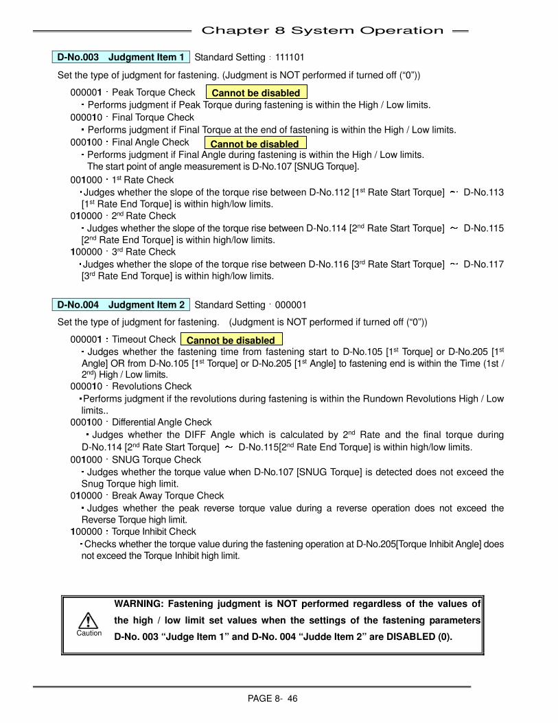
Chapter 8 System Operation
PAGE 8- 46
D-No.003
Judgment Item 1 Standard Setting:111101
Set the type of judgment for fastening. (Judgment is NOT performed if turned off (“0”))
000001:Peak Torque Check
・Performs judgment if Peak Torque during fastening is within the High / Low limits.
000010:Final Torque Check
・Performs judgment if Final Torque at the end of fastening is within the High / Low limits.
000100:Final Angle Check
・Performs judgment if Final Angle during fastening is within the High / Low limits.
The start point of angle measurement is D-No.107 [SNUG Torque].
001000:1st Rate Check
・Judges whether the slope of the torque rise between D-No.112 [1st Rate Start Torque] ~ D-No.113
[1st Rate End Torque] is within high/low limits.
010000:2nd Rate Check
・Judges whether the slope of the torque rise between D-No.114 [2nd Rate Start Torque] ~ D-No.115
[2nd Rate End Torque] is within high/low limits.
100000:3rd Rate Check
・Judges whether the slope of the torque rise between D-No.116 [3rd Rate Start Torque] ~ D-No.117
[3rd Rate End Torque] is within high/low limits.
D-No.004
Judgment Item 2 Standard Setting:000001
Set the type of judgment for fastening. (Judgment is NOT performed if turned off (“0”))
000001:Timeout Check
・Judges whether the fastening time from fastening start to D-No.105 [1st Torque] or D-No.205 [1st
Angle] OR from D-No.105 [1st Torque] or D-No.205 [1st Angle] to fastening end is within the Time (1st / 2nd) High / Low limits.
000010:Revolutions Check
・Performs judgment if the revolutions during fastening is within the Rundown Revolutions High / Low
limits..
000100:Differential Angle Check
・Judges whether the DIFF Angle which is calculated by 2nd Rate and the final torque during
D-No.114 [2nd Rate Start Torque] ~ D-No.115[2nd Rate End Torque] is within high/low limits.
001000:SNUG Torque Check
・Judges whether the torque value when D-No.107 [SNUG Torque] is detected does not exceed the
Snug Torque high limit.
010000:Break Away Torque Check
・Judges whether the peak reverse torque value during a reverse operation does not exceed the
Reverse Torque high limit.
100000:Torque Inhibit Check
・Checks whether the torque value during the fastening operation at D-No.205[Torque Inhibit Angle] does
not exceed the Torque Inhibit high limit.
WARNING: Fastening judgment is NOT performed regardless of the values of
the high / low limit set values when the settings of the fastening parameters
D-No. 003 “Judge Item 1” and D-No. 004 “Judde Item 2” are DISABLED (0).
Cannot be disabled
Cannot be disabled
Cannot be disabled
Caution
Chapter 8 System Operation
PAGE 8- 47
D-No.005
Judgment Item 3 Standard Setting:000000
Set the type of Rate start and end for Rate Judgment.
000001: Rate 1 Start item select
・0:D-No. 112 [Rate 1 Start Torque] is set as a start point of Rate 1.
・1:D-No. 208 [Rate 1 Start Angle] is set as a start point of Rate 1.
000010: Rate 1 End item select
・0:D-No. 113 [Rate 1 End Torque] is set as a end point of Rate 1.
・1:D-No. 209 [Rate 1 End Angle] is set as a end point of Rate 1.
000100: Rate 2 Start item select
・0:D-No. 114 [Rate 2 Start Torque] is set as a start point of Rate 2.
・1:D-No. 210 [Rate 2 Start Angle] is set as a start point of Rate 2.
001000: Rate 2 End item select
・0:D-No. 115 [Rate 2 End Torque] is set as a end point of Rate 2.
・1:D-No. 211 [Rate 2 End Angle] is set as a end point of Rate 2.
010000: Rate 3 Start item select
・0:D-No. 116 [Rate 3 Start Torque] is set as a start point of Rate 3.
・1:D-No. 212 [Rate 3 Start Angle] is set as a start point of Rate 3.
100000: Rate 3 End item select
・0:D-No. 117 [Rate 3 End Torque] is set as a end point of Rate 3.
・1:D-No. 213 [Rate 3 End Angle] is set as a end point of Rate 3.

Chapter 8 System Operation
PAGE 8- 48
D-No.006
After Fastening Operation Standard Setting:0000
Set the operation to be performed after the fastening operation is complete.
0001:1 Pulse Reverse
・Prevent a socket from sticking after the fastening ends.
Reverse at D-No. 408 [Reverse 3 Speed] during D-No.321 [1 Pulse Reverse Time]. After the end of fastening, torque is applied to the D-No.120 [1 Pulse Reverse Torque High Limit].
0010:Reduce Fastening Reaction
・Reduces the release of torque energy at the end of a fastening cycle by gradually releasing the torque
over a given time period. Normally, the motor power is turned off when the target torque / angle is reached which can cause an abrupt ‘jerking motion’ when the torque energy is released – the use of this function reduces this by allowing the energy to dissipate more smoothly. This function is helpful in operator held applications and also may help reduce wear of tooling at high torque levels where torque reaction can be very high.
0100:Torque Recovery
・Once Standard Torque is reached, the torque is maintained for D-No.315 [Torque Recovery Time].
The fastening speed during torque recovery is set at D-No. 404 [3rd Speed] (Should be no more than 3rpm or 5rpm.)
1000:Servo Lock
・At the end of a cycle with Servo Lock enabled, the motor rotor is electrically locked to prevent
rotation of the tool. (External gears, socket and/or socket extensions may experience slight movement even though the servo lock is enabled due to backlash in the drive connections). The function will also work in the Reverse direction using the Reverse input signal or Reverse 1-3 being called from a internal sequence.
The fastening result data is output after the Servo Lock is released. The real time monitoring is available while the Servo Lock is on. A RESET pulse <500msec can be used to stop and hold/lock the spindle while rotating in cycle. (a RESET pulse >500msec will reset and turn off the hold/lock function) Servo Lock can be released when a START signal is ON, RESET signal is ON, BYPASS signal is ON, or STOP is OFF. (use of this function can be monitored from the controller display in the Fastening Result Mode: D-No. 16 “Servo Lock Flag” would be set to “1”.
D-No.007
Output Judgment Item 4 Standard Setting:000000
Set the type of Rate start and end for Rate Judgment.
000001: 1st Peak Torque Judgment
・Whether or not the torque value is within the high limit range is judged when D-No. 105 [1st
Torque] or D-No. 203[1st Angle] is detected.
*The judgment is not performed if the fastening parameter D-No. 001 [Fastening Steps] is 1 step.
D-No.008
Fastenening Option 2 Standard Setting:000000
000001: Return to Freerun Speed if torque drops below Ramp Down Start Torque
・Once D-No.104 [Ramp Down Start Torque] is detected, if the fastening torque drops below the
Ramp Down Start Torque still within D-No.500 [Freerun Revolutions], the fastening speed is switched back to D-No.401 [Freerun Speed] from D-No.402 [1st Speed].
D-No. 009 Option D-No. 010 Option Standard setting: 000000
Not Used.
Chapter 8 System Operation
PAGE 8- 49
8-7-4 Fastening Parameters (Torque) D-No.100 Calibration Torque (Full Scale Torque) [Nm]
Setting Range:80%~120% of tool standard Full Scale Torque
Set the Full Scale Torque value of the connected tools.
The calibration value is set according to the tool type (capacity). However, depending on the application characteristics or the prevailing torque generated external to the tool output shaft, the value of the applied torque and the torque display by the MFC controller may not match. In this case, it is possible to adjust the FULL SCALE TORQUE (CAL) value so the displayed torque matches the installation torque registered by an external torque transducer (Master).
New Full Scale Torque value =
Mean Torque from an external Torque Transducer (Master) ÷ Mean Torque from FEC Transducer × Existing Full Scale Torque
Ex:D-No.100 [Full Scale Torque] :294.2Nm
Mean FEC Torque :200.0Nm in this case
Mean Master Torque:210.0Nm
210.0Nm ÷ 200.0Nm × 294.2Nm = 308.9Nm The Full Scale Torque should be changed to 308.9Nm.
・ If the Full Scale Torque calibration needs to be changed, the mean of the fastening result data is used as the measured value. (The number of samples of fastening result data is recommended to be at least 10 as a statistical standard.)
・ When the calibration value is changed, confirm that other torque parameters are lower than the new Calibration value (or the new CAL value may not be able to be entered) Other torque related parameters should be set lower than the tool’s max torque value and Full Scale Torque.
・ ANY CHANGES TO THE CALIBRATION TORQUE SHOULD BE DONE BY QUALIFIED PERSONNEL ONLY (output torque results may differ if not correctly changed)
D-No.101 Peak Torque Low Limit [Nm] D-No.102 Peak Torque High Limit [Nm]
Setting Range:0~D-No.100 [Full Scale Torque] ×1.1
Set points for the high/low limits of the fastening torque.
If the fastening torque exceeds the D-No.102 [Peak Torque High Limit] or does not reach the D-No.101 [Peak Torque Low Limit], the fastening judgment will be REJECT.
D-No.103 Standard Torque [Nm] Setting Range:0~D-No.010 [Full Scale Torque]×1.0
Set point of the fastening standard (Target) torque. This function is only available when the D-No.000 [Fastening Type] is Torque Control Method
Ex.: If 10.0 is set, the controller attempts to fasten until the torque value 10.0[Nm] is reached.
【
【【
【Warning Regarding Fastening】】】
】
Avoid fastening to a torque that exceeds the full scale torque of tool.
Keep the duty cycle (the ratio between the fastening time and tool idle time) below
60% even when the fastening is below the full scale torque of tool fastening.
Refer to Section 2-1-4 “Duty Cycle Calculation”
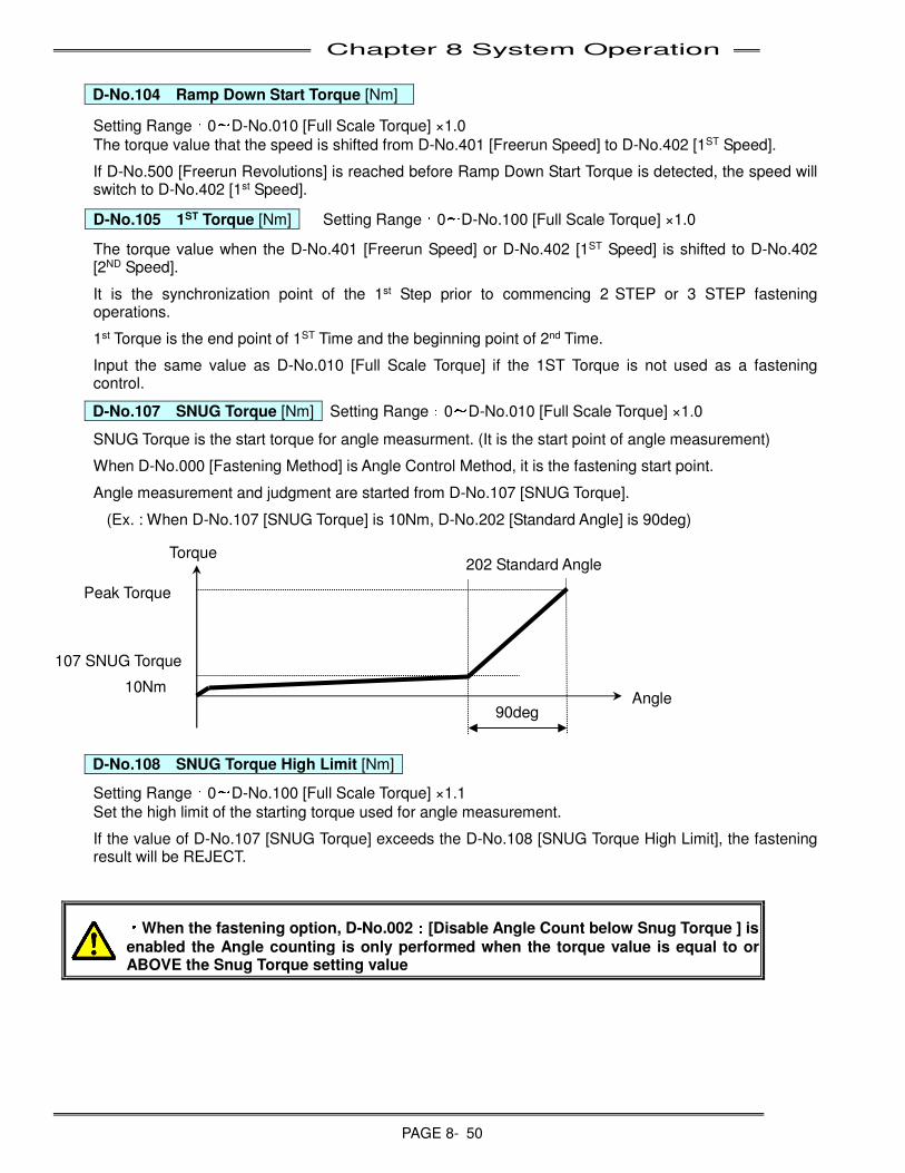
Chapter 8 System Operation
PAGE 8- 50
D-No.104
Ramp Down Start Torque [Nm]
Setting Range:0~D-No.010 [Full Scale Torque] ×1.0
The torque value that the speed is shifted from D-No.401 [Freerun Speed] to D-No.402 [1ST Speed].
If D-No.500 [Freerun Revolutions] is reached before Ramp Down Start Torque is detected, the speed will switch to D-No.402 [1st Speed].
D-No.105
1ST Torque [Nm] Setting Range:0~D-No.100 [Full Scale Torque] ×1.0
The torque value when the D-No.401 [Freerun Speed] or D-No.402 [1ST Speed] is shifted to D-No.402 [2ND Speed].
It is the synchronization point of the 1st Step prior to commencing 2 STEP or 3 STEP fastening operations.
1st Torque is the end point of 1ST Time and the beginning point of 2nd Time.
Input the same value as D-No.010 [Full Scale Torque] if the 1ST Torque is not used as a fastening control.
D-No.107
SNUG Torque [Nm] Setting Range:0~D-No.010 [Full Scale Torque] ×1.0
SNUG Torque is the start torque for angle measurment. (It is the start point of angle measurement)
When D-No.000 [Fastening Method] is Angle Control Method, it is the fastening start point.
Angle measurement and judgment are started from D-No.107 [SNUG Torque].
(Ex. : When D-No.107 [SNUG Torque] is 10Nm, D-No.202 [Standard Angle] is 90deg)
D-No.108
SNUG Torque High Limit [Nm]
Setting Range:0~D-No.100 [Full Scale Torque] ×1.1
Set the high limit of the starting torque used for angle measurement.
If the value of D-No.107 [SNUG Torque] exceeds the D-No.108 [SNUG Torque High Limit], the fastening result will be REJECT.
・
・・
・When the fastening option, D-No.002:::
:[Disable Angle Count below Snug Torque ] is
enabled the Angle counting is only performed when the torque value is equal to or ABOVE the Snug Torque setting value
107 SNUG Torque
10Nm
202 Standard Angle Torque
Angle 90deg
Peak Torque
Chapter 8 System Operation
PAGE 8- 51
D-No.109
2ND Torque [Nm] Setting Range:0~D-No.100 [Full Scale Torque] ×1.0
The torque value that the speed is shifted from D-No.402 [2ND Speed] to D-No.403 [3RD Speed].
It is a synchronization point of the 2nd STEP prior to commencing a 3 STEP fastening operation.
*Input the same value as D-No.010 [Full Scale Torque] if the 2ND Torque is not used as a fastening control.
D-No.110
Reverse Torque High Limit [Nm]
Setting Range:0~D-No.100 [Full Scale Torque] ×1.1
Set the torque high limit during a reverse operation.
If the reverse torque exceeds the D-No.110 [Reverse Torque High Limit] during reverse operation, the fastening stops and the abnormal signal A.9-8 [Reverse Torque Abnormal] will be generated.
D-No.111
Torque Inhibit Limit [Nm]
Setting Range:0~D-No.100 [Full Scale Torque] ×1.1
Limit for ignoring the Torque sensed at the start of fastening (due to large mass inertia or high prevailing torque applications (self threading / tapping applications)
Torque Inhibit is conducted from fastening start to the D-No.205 [Torque Inhibit Angle] value.
If the torque exceeds D-No.111 [Torque Inhibit Limit] before reaching the D-No.205 [Torque Inhibit Angle] the fastening result will be REJECT.
D-No.112
1ST Rate Start Torque [Nm] D-No.113
1ST Rate End Torque [Nm]
Setting Range:0~D-No.100 [Full Scale Torque] ×1.0
Set the start and end points for measuring 1ST Torque Rate.
Judgment of the torque slope (torque vs angle) is performed between D-No.112 [1ST Rate Start Torque] and D-No.113 [1ST Rate End Torque].
D-No.114
2ND Rate Start Torque [Nm] D-No.115
2ND Rate End Torque [Nm]
Setting Range:0~D-No.100 [Full Scale Torque] ×1.0
Set the start and end points for measuring 2ND Torque Rate.
Judgment of the torque slope (torque vs angle) is performed between D-No.114 [2ND Rate Start Torque] and D-No.115 [2ND Rate End Torque].
D-No.116
3RD Rate Start Torque [Nm] D-No.117
3RD Rate End Torque [Nm]
Setting Range:0~D-No.100 [Full Scale Torque] ×1.0
Set the start and end points for measuring 3RD Torque Rate.
Judgement of the torque slope (torque vs angle) is performed between D-No.116 [3RD Rate Start Torque] and D-No.117 [3RD Rate End Torque].
D-No.118 Final Torque Low Limit [Nm] D-No.119 Final Torque High Limit [Nm]
Setting Range:0~D-No.100 [Full Scale Torque] ×1.1
When the D-No.000 [Fastening Method] is Angle Control Method, this sets the high and low limits for fastening torque at the point that the standard (target) angle is achieved. If the fastening torque exceeds the D-No.119 [Final Torque High Limit] or is lower than the D-No.118 [Final Torque Low Limit], the fastening result will be REJECT.
When the D-No.000 [Fastening Method] is Torque Control Method, this does not need to be set. (Only in the case TORQUE RECOVERY is used to check that fastener breakage does not occur during torque recovery)
When D-No. 000 [Fastening Method] is [Offset Check], final torque is set as the high limit value of the
average torque detected during D-No.505 [Offset Check Revolutions]
If the average torque exceeds the final torque high limit, fastening judgment will be REJECT
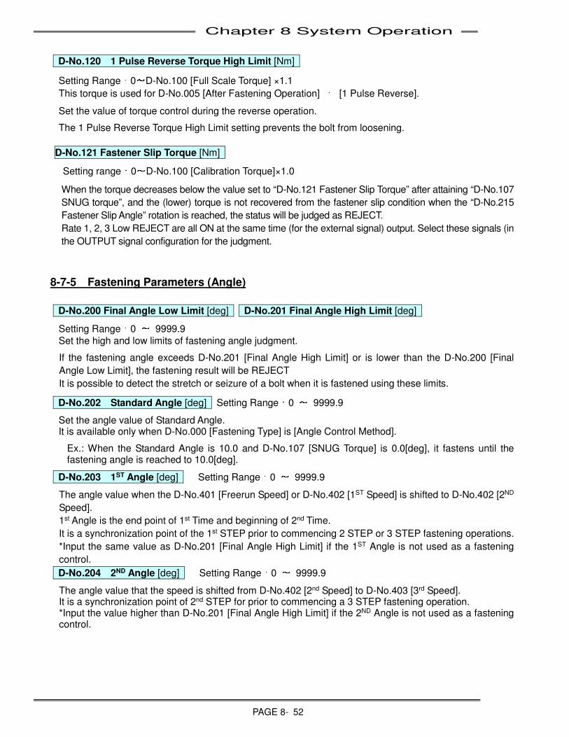
Chapter 8 System Operation
PAGE 8- 52
D-No.120
1 Pulse Reverse Torque High Limit [Nm]
Setting Range:0~D-No.100 [Full Scale Torque] ×1.1
This torque is used for D-No.005 [After Fastening Operation] : [1 Pulse Reverse].
Set the value of torque control during the reverse operation.
The 1 Pulse Reverse Torque High Limit setting prevents the bolt from loosening.
D-No.121 Fastener Slip Torque [Nm]
Setting range:0~D-No.100 [Calibration Torque]×1.0
When the torque decreases below the value set to “D-No.121 Fastener Slip Torque” after attaining “D-No.107
SNUG torque”, and the (lower) torque is not recovered from the fastener slip condition when the “D-No.215
Fastener Slip Angle” rotation is reached, the status will be judged as REJECT.
Rate 1, 2, 3 Low REJECT are all ON at the same time (for the external signal) output. Select these signals (in
the OUTPUT signal configuration for the judgment.
8-7-5 Fastening Parameters (Angle)
D-No.200 Final Angle Low Limit [deg] D-No.201 Final Angle High Limit [deg]
Setting Range:0 ~ 9999.9
Set the high and low limits of fastening angle judgment.
If the fastening angle exceeds D-No.201 [Final Angle High Limit] or is lower than the D-No.200 [Final
Angle Low Limit], the fastening result will be REJECT
It is possible to detect the stretch or seizure of a bolt when it is fastened using these limits.
D-No.202
Standard Angle [deg] Setting Range:0 ~ 9999.9
Set the angle value of Standard Angle. It is available only when D-No.000 [Fastening Type] is [Angle Control Method].
Ex.: When the Standard Angle is 10.0 and D-No.107 [SNUG Torque] is 0.0[deg], it fastens until the fastening angle is reached to 10.0[deg].
D-No.203
1ST Angle [deg] Setting Range:0 ~ 9999.9
The angle value when the D-No.401 [Freerun Speed] or D-No.402 [1ST Speed] is shifted to D-No.402 [2ND
Speed].
1st Angle is the end point of 1st Time and beginning of 2nd Time.
It is a synchronization point of the 1st STEP prior to commencing 2 STEP or 3 STEP fastening operations.
*Input the same value as D-No.201 [Final Angle High Limit] if the 1ST Angle is not used as a fastening
control.
D-No.204
2ND Angle [deg] Setting Range:0 ~ 9999.9
The angle value that the speed is shifted from D-No.402 [2nd Speed] to D-No.403 [3rd Speed]. It is a synchronization point of 2nd STEP for prior to commencing a 3 STEP fastening operation. *Input the value higher than D-No.201 [Final Angle High Limit] if the 2ND Angle is not used as a fastening control.
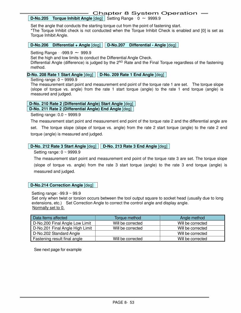
Chapter 8 System Operation
PAGE 8- 53
D-No.205
Torque Inhibit Angle [deg] Setting Range:0 ~ 9999.9
Set the angle that conducts the starting torque cut from the point of fastening start. *The Torque Inhibit check is not conducted when the Torque Inhibit Check is enabled and [0] is set as Torque Inhibit Angle.
D-No.206
Differential + Angle [deg] D-No.207
Differential - Angle [deg]
Setting Range:-999.9 ~ 999.9
Set the high and low limits to conduct the Differential Angle Check. Differential Angle (difference) is judged by the 2ND Rate and the Final Torque regardless of the fastening method.
D-No. 208 Rate 1 Start Angle [deg] D-No. 209 Rate 1 End Angle [deg] Setting range: 0 ~ 9999.9 The measurement start point and measurement end point of the torque rate 1 are set. The torque slope (slope of torque vs. angle) from the rate 1 start torque (angle) to the rate 1 end torque (angle) is measured and judged.
D-No. 210 Rate 2 (Differential Angle) Start Angle [deg]
D-No. 211 Rate 2 (Differential Angle) End Angle [deg]
Setting range: 0.0 ~ 9999.9
The measurement start point and measurement end point of the torque rate 2 and the differential angle are
set. The torque slope (slope of torque vs. angle) from the rate 2 start torque (angle) to the rate 2 end
torque (angle) is measured and judged.
D-No. 212 Rate 3 Start Angle [deg] D-No. 213 Rate 3 End Angle [deg]
Setting range: 0 ~ 9999.9
The measurement start point and measurement end point of the torque rate 3 are set. The torque slope
(slope of torque vs. angle) from the rate 3 start torque (angle) to the rate 3 end torque (angle) is
measured and judged.
D-No.214 Correction Angle [deg]
Setting range: -99.9 ~ 99.9 Set only when twist or torsion occurs between the tool output square to socket head (usually due to long extensions, etc.) Set Correction Angle to correct the control angle and display angle. Normally set to 0.
Data Items affected Torque method Angle method
D-No.200 Final Angle Low Limit Will be corrected Will be corrected D-No.201 Final Angle High Limit Will be corrected Will be corrected D-No.202 Standard Angle
- Will be corrected Fastening result final angle Will be corrected Will be corrected
See next page for example
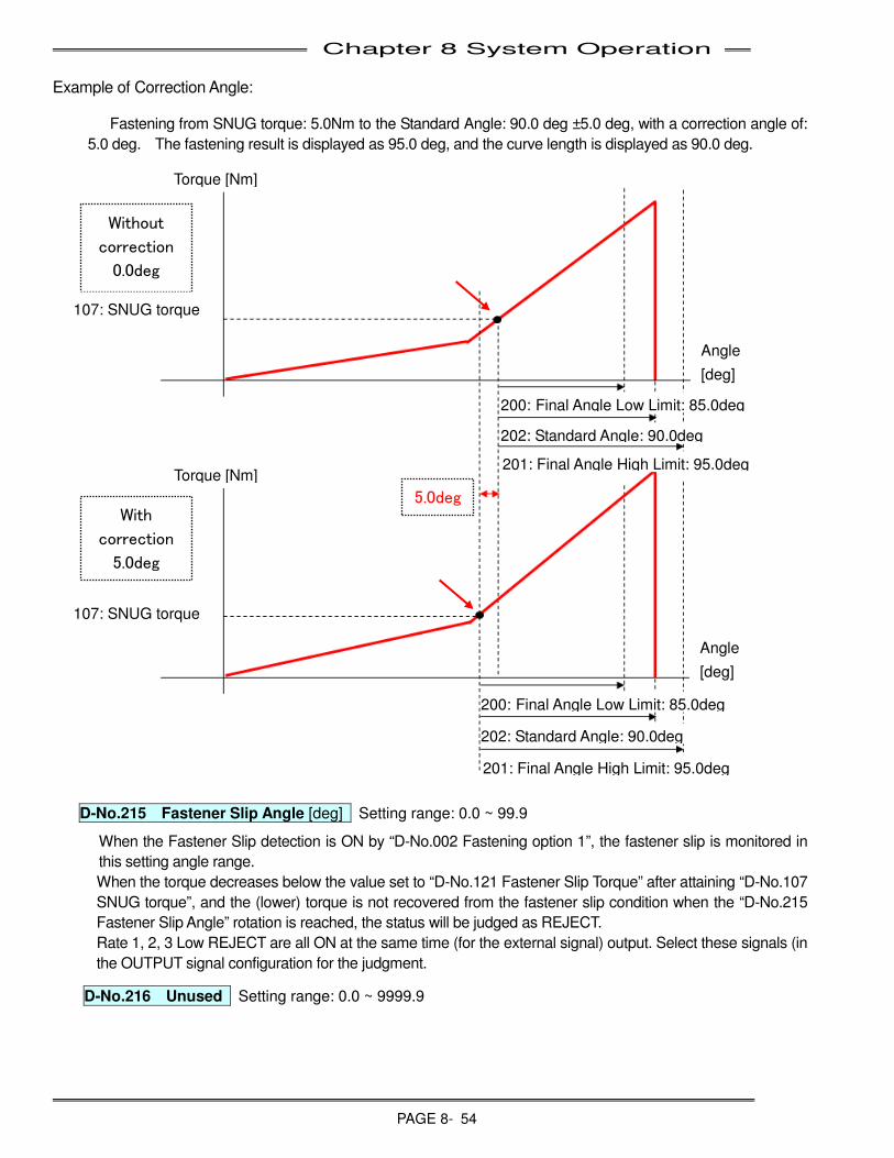
Chapter 8 System Operation
PAGE 8- 54
Example of Correction Angle:
Fastening from SNUG torque: 5.0Nm to the Standard Angle: 90.0 deg ±5.0 deg, with a correction angle of:
5.0 deg. The fastening result is displayed as 95.0 deg, and the curve length is displayed as 90.0 deg.
D-No.215 Fastener Slip Angle [deg] Setting range: 0.0 ~ 99.9
When the Fastener Slip detection is ON by “D-No.002 Fastening option 1”, the fastener slip is monitored in
this setting angle range.
When the torque decreases below the value set to “D-No.121 Fastener Slip Torque” after attaining “D-No.107
SNUG torque”, and the (lower) torque is not recovered from the fastener slip condition when the “D-No.215
Fastener Slip Angle” rotation is reached, the status will be judged as REJECT.
Rate 1, 2, 3 Low REJECT are all ON at the same time (for the external signal) output. Select these signals (in
the OUTPUT signal configuration for the judgment.
D-No.216
Unused Setting range: 0.0 ~ 9999.9
Without
correction
0.0deg
With
correction
5.0deg
Angle
[deg]
Torque [Nm]
107: SNUG torque
200: Final Angle Low Limit: 85.0deg
202: Standard Angle: 90.0deg
201: Final Angle High Limit: 95.0deg
200: Final Angle Low Limit: 85.0deg
202: Standard Angle: 90.0deg
201: Final Angle High Limit: 95.0deg
Angle
[deg]
Torque [Nm]
107: SNUG torque
5.0deg
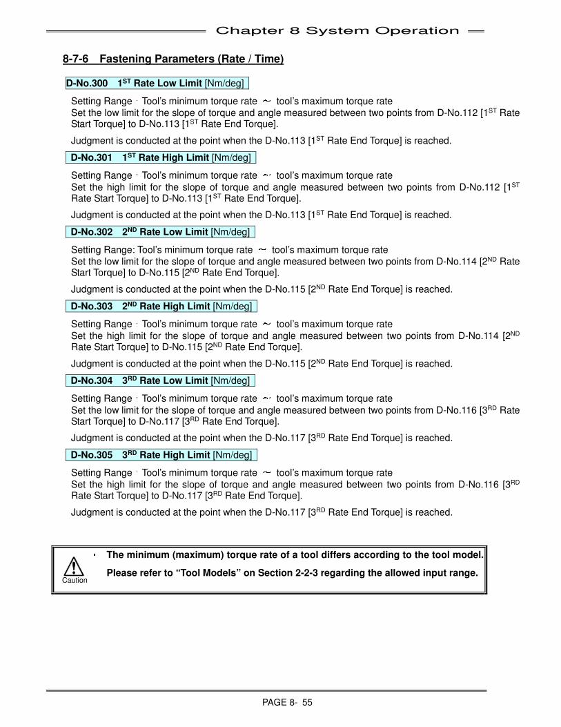
Chapter 8 System Operation
PAGE 8- 55
8-7-6 Fastening Parameters (Rate / Time) D-No.300
1ST Rate Low Limit [Nm/deg]
Setting Range:Tool’s minimum torque rate ~ tool’s maximum torque rate
Set the low limit for the slope of torque and angle measured between two points from D-No.112 [1ST Rate Start Torque] to D-No.113 [1ST Rate End Torque].
Judgment is conducted at the point when the D-No.113 [1ST Rate End Torque] is reached.
D-No.301
1ST Rate High Limit [Nm/deg]
Setting Range:Tool’s minimum torque rate ~ tool’s maximum torque rate
Set the high limit for the slope of torque and angle measured between two points from D-No.112 [1ST Rate Start Torque] to D-No.113 [1ST Rate End Torque].
Judgment is conducted at the point when the D-No.113 [1ST Rate End Torque] is reached.
D-No.302
2ND Rate Low Limit [Nm/deg]
Setting Range: Tool’s minimum torque rate ~ tool’s maximum torque rate
Set the low limit for the slope of torque and angle measured between two points from D-No.114 [2ND Rate Start Torque] to D-No.115 [2ND Rate End Torque].
Judgment is conducted at the point when the D-No.115 [2ND Rate End Torque] is reached.
D-No.303
2ND Rate High Limit [Nm/deg]
Setting Range:Tool’s minimum torque rate ~ tool’s maximum torque rate
Set the high limit for the slope of torque and angle measured between two points from D-No.114 [2ND Rate Start Torque] to D-No.115 [2ND Rate End Torque].
Judgment is conducted at the point when the D-No.115 [2ND Rate End Torque] is reached.
D-No.304
3RD Rate Low Limit [Nm/deg]
Setting Range:Tool’s minimum torque rate ~ tool’s maximum torque rate
Set the low limit for the slope of torque and angle measured between two points from D-No.116 [3RD Rate Start Torque] to D-No.117 [3RD Rate End Torque].
Judgment is conducted at the point when the D-No.117 [3RD Rate End Torque] is reached.
D-No.305
3RD Rate High Limit [Nm/deg]
Setting Range:Tool’s minimum torque rate ~ tool’s maximum torque rate
Set the high limit for the slope of torque and angle measured between two points from D-No.116 [3RD Rate Start Torque] to D-No.117 [3RD Rate End Torque].
Judgment is conducted at the point when the D-No.117 [3RD Rate End Torque] is reached.
・
・・
・ The minimum (maximum) torque rate of a tool differs according to the tool model.
Please refer to “Tool Models” on Section 2-2-3 regarding the allowed input range. Caution
Chapter 8 System Operation
PAGE 8- 56
D-No.310 Initial Time [sec] Setting Range: 0 ~ 999.9
Set the time accordingly to mitigate shock occurred at the fastening start time or to slowly engage a fastener (to improve engagement). During the D-No.310 [Initial Time], the start of the fastening will be conducted at D-No.400 [Initial Speed].
When D-No.310 [Initial Time] is set as “0.0”, the operation will start in D-No.401 [Freerun Speed].
D-No.311
1ST Time Low Limit [sec] Setting Range:0 ~ 999.9
Set the time low limit between the start of fastening and the point D-No.105 [1ST Torque] or D-No.203 [1ST Angle] is reached.
When the 1ST Time Low Limit is not reached, the fastening judgment will be REJECT.
D-No.312
1ST Time High Limit [sec] Setting Range:0 ~ 999.9
Set the time high limit between the start of fastening and the point D-No.105 [1ST Torque] or D-No.203 [1ST Angle] is reached. Allow enough time to reach 1st Torque, but not so much time that cycle time would be unacceptable if no fastener is present (or does not engage).
When the 1ST Time High Limit is exceeded, the fastening judgment will be REJECT .
D-No.313
2ND Time Low Limit [sec] Setting Range:0 ~ 999.9
Set the time low limit between D-No.105 [1ST Torque] or D-No.203 [1ST Angle] and the point D-No.103 [Standard Torque] or D-No.202 [Standard Angle] is reached.
When the 2ND Time Low Limit is not reached, the fastening judgment will be REJECT .
D-No.314
2ND Time High Limit [sec] Setting Range:0 ~ 999.9
Set the time high limit between D-No.105 [1ST Torque] or D-No.203 [1ST Angle] and the point D-No.103 [Standard Torque] or D-No.202 [Standard Angle] is reached. Allow enough time to reach Standard Torque (from 1st Torque).
When the 2ND Time High Limit is exceeded, the fastening judgment will be REJECT .
D-No.315
Torque Recovery Time [sec] Setting Range:0 ~ 5.0
After fastening, Standard torque is maintained for this specified time.
• This is not normally required and should be used with caution. (Mainly used for applications where “joint relaxation” may occur) If time is set too long or causes duty cycle to go above 60%, abnormal A.8-10 “Overload Abnormal” may occur.
D-No.318
Ramp Up Time [sec]* Setting Range:0.1 ~ 5.0
Set the time constant from the ZERO speed to when the tool’s maximum speed is reached.
D-No.319
Ramp Down Time [sec]* Setting Range:0.1 ~ 5.0
Set the time constant from the tool’s maximum speed to when ZERO speed is reached from D-No. 104 [Ramp Down Start Torque]
D-No.320
Freerun Ramp Down Time [sec]* Setting Range:0.1 ~ 5.0
Set the time constant from the tool’s maximum speed to when ZERO speed is reached from D-No. 500 [Freerun Revolutions]
D-No.321
1 Pulse Reverse Time [sec]* Setting Range:0 ~ 999.9
This is time used for D-No.005 [After Fastening Operation] :“1 Pulse Reverse”.
Set the operation time of D-No.XXX [1 Pulse Reverse Speed]
*Note: Unless required by special application, do not change D-No. 318, 319 or 320. These are set automatically for optimum performance.
Chapter 8 System Operation
PAGE 8- 57
D-No. 322 Final Ramp Down Time [sec] Setting range: 0.00 ~ 5.00, standard setting: 0.00
The time constant for deceleration from the maximum rotation speed of a tool to zero speed upon reaching
D-No. 202 [Standard Angle] in the fastening operation is set using this. This is available only when D-No.
000 [Fastening Method] is “Angle Method.” This is used to protect the tool motor when a sudden stop
operation is performed during high speed rotation for a loosening operation, etc.
D-No.323 Reverse Ramp Up Time [sec] Setting range: 0.10 ~ 5.00, standard setting: 0.50
This (option) sets the acceleration time constant to reach the tool maximum rotation speed from zero speed in the manual reverse rotation 1, 2, and 3.
8-7-7 Fastening Parameters (Speed) D-No.400
Initial Speed [rpm]
Setting Range:Tool’s minimum to maximum number of rotations.
Set the speed accordingly to mitigate shock occurred at the fastening start time or to slowly engage a fastener (to improve engagement).
During the D-No.310 [Initial Time], the start of the fastening will be conducted at D-No.400 [Initial Speed].
When D-No.310 [Initial Time] is set as “0.0”, the operation will start in D-No.401 [Freerun Speed].
D-No.401
Freerun Speed [rpm]
Setting Range:Tool’s minimum to maximum number of rotation.
Set the high speed rotation after D-No.400 [Initial Speed] ends.
The system rotates at the D-No.401 [Freerun Speed] during the D-No.500 [Freerun Revolutions] or until the D-No.310 [Ramp Down Start Torque] is reached.
D-No.402
1ST Speed [rpm]
Setting Range:Tool’s minimum to maximum number of rotations.
Set the speed between D-No.401 [Freerun Speed] and D-No.403 [2ND Speed].
The system rotates at the 1ST Speed until D-No.105 [1ST Torque] is detected from D-No.104 [Slow Down Start Torque] or until D-No.203 [1ST Angle] is detected from D-No.104 [Ramp Down Start Torque].
*If D-No.105 [1ST Torque] or D-No.203 [1ST Angle] is reached during the D-No.401 [Freerun Speed], 1ST Speed will be switched over to D-No.403 [2ND Speed].
D-No.403
2ND Speed [rpm]
Setting Range:Tool’s minimum to maximum number of rotations.
Set the speed after 2-STEP.
This is the speed after D-No.105 [1ST Torque] or D-No.203 [1ST Angle] is detected.
* Fastening accuracy is improved the slower the 2ND Speed is set.
D-No.404
3RD Speed [rpm]
Setting Range:Tool’s minimum to maximum number of rotations.
Set the speed after 3-STEP.
This is the speed after D-No.106 [2ND Torque] or D-No.204 [2ND Angle] is detected.
* Fastening accuracy is improved the slower the 3rd Speed is set.
Set the same value as D-No.403 [2ND Speed], if the 3RD Speed is not used.
Chapter 8 System Operation
PAGE 8- 58
D-No.406
Reverse 1 Speed [rpm]
Setting Range:Tool’s minimum to maximum number of rotations.
Set the speed during the reverse operation.
This is the reverse speed used while the REV switch on the controller display unit is pressed.
When the D-No.110 [Reverse Torque High Limit] is exceeded during the reverse operation, the fastening will stop and the abnormal signal A.9-8 [Reverse Torque Error] will be displayed.
D-No.407
Reverse 2 Speed [rpm]
Setting Range:Tool’s minimum to maximum number of rotations.
Set the speed during the reverse operation. Reverse 2 can be selected as a reverse option in any internal sequence.
In a Single System. this is the speed used for D-No.002 [Fastening Option]:[Reverse Before Fastening]
When the D-No.110 [Reverse Torque High Limit] is exceeded during the reverse operation, the fastening will stop and the abnormal signal A.9-8 [Reverse Torque Error] will be displayed.
D-No.408
Reverse 3 Speed [rpm]
Setting Range:Tool’s minimum to maximum number of rotations.
Set the speed during the reverse operation.
Reverse 3 can be selected as a reverse option in any internal sequence.
This is the speed used for D-No.005 [After Fastening Operation]:[1 Pulse Reverse].
When the D-No.110 [Reverse Torque High Limit] is exceeded during the reverse operation, the fastening will stop and the abnormal signal A.9-8 [Reverse Torque Error] will be displayed.
D-No.409
Offset Check Speed [rpm]
Setting Range:Tool’s minimum to maximum speed.
Set the speed during the offset check operation.
Chapter 8 System Operation
PAGE 8- 59
8-7-8 Fastening Parameters (Revolutions / Number of Rotations / Current)
D-No.500
Freerun Revolutions [rev] Setting Range:0 ~ 99.9
Set the number of revolutions before D-No.401 [Freerun Speed] is switched to D-No.402 [1ST Speed].
Even if the Freerun Speed Revolution is not reached, it switches to D-No.402 [1ST Speed] when the D-No.104 [Ramp Down Start Torque] is detected.
D-No.501
Reverse 2 Revolutions [rev] Setting Range:0 ~ 99.9
Used for D-No.002 [Fastening Option]:[Reverse Before Fastening]. Also it is used for fastening sequence
command [Reverse 2].
D-No.502
Reverse 3 Revolutions [rev] Setting Range:0 ~ 99.9
Used for fastening sequence command [Reverse 3].
D-No.503
Rundown Revolution Low Limit [rev]
D-No.504
Rundown Revolution High Limit [rev]
Setting Range:0 ~ 99.9
Set the high and low limits of the number of rotated revolutions from the beginning of the fastening to the end.
When the number of rotations exceeds the D-No.504 [Rundown Revolution High Limit] at the time of
fastening end, or if D-No.503「Rundown Revolution Low Limit」is not reached, the fastening result will be
REJECT.
D-No.505
Offset Check Revolutions [rev] Setting Range:0 ~ 99.9
Used for D-No.002 [Fastening Option]:[Reverse Before Fastening]. Also it is used for fastening sequence
command [Reverse 2].
D-No.520
Full Scale Current [A] D-No.521
Low Current Limit [A]
D-No.522
High Current Limit [A] D-No.523
Fastening Current Limit [A]
Setting Range:0 ~ Due to controller type
Set the values below according to the combination of controller type and tool type.
Controller Type
Tool Type D-No.520 Full Scale
Current [A]
D-No.521 Low Current
Limit [A]
D-No.522 High Current
Limit [A]
D-No.523 Fastening
Current Limit [A]
MFC-S008 MFT-□□□M10-□ 8.0 0.0 8.0 8.0
MFC-S024 CFT-□□□RS1-□ 24.0 0.0 24.0 24.0
MFC-S060 CFT-□□□RS3-□ 60.0 0.0 60.0 60.0
MFC-S120 CFT-□□□RS4-□ 120.0 0.0 120.0 120.0
When the actual fastening current falls outside the range defined by D-No. 521 “Low Current Limit” and D-No. 522 “High Current Limit,” although the Unit outputs the ACCEPT fastening judgment, the PLC output layout output signal “Multi: Current Limit Warning,” “Axis: Low Current Value Limit Warning,” “Axis: High Current Limit Value Warning,” or “Current Limit Warning” to “ON.”

Chapter 8 System Operation
PAGE 8- 60
(Blank Page)
Chapter 9 Maintenance & Inspection
PAGE 9-1
Chapter 9: Maintenance & Inspection
9
Chapter 9 Maintenance & Inspection
PAGE 9-2
9-1 Inspection Items
A scheduled inspection is recommended to keep the AFC3000 System in the best condition. A preventive maintenance routine should be set-up. Recommended inspection schedules are given for each item.
9-1-1 Tools (Motors)
Mechanical degradation and malfunction are predicted for the tools because a powerful torque is applied each time fastening is performed.
(Inpect Quarterly)
• All environmental conditions are within the specified ranges.
• The duty cycle is within specifications, and the motor is producing normal heat levels
• The tool is producing normal levels of noise and vibration.
• The tool is free from excessive contamination and foreign matter.
• The tool is securely mounted, with mounting bolts properly tightened.
• The tool is not touched with any other object. The tool is free from unnecessary force and tension other than in the fastening direction.
9-1-2 Spindle Assembly
The Spindle Assembly is a spring loaded driver extension which permits travel of the driver as a fastener is fastened so that a multi-spindle head can be advanced to a single stop point without the problem of the fastener running out of the driver during the fastening process. The torque and stress generated during each fastening is applied directly to the spindle assembly. Inspect each assembly, and ensure the following specifications are met: .
(Inspect Monthly)
• The spindle assembly is producing normal levels of noise and vibration.
• The assembly is free from excessive contamination and foreign matter.
• The spindle assembly is securely mounted, with mounting bolts properly tightened.
• The square drive or socket is in good condition, and there is no excessive wear.
• The spindle assembly rotates and compresses freely, with no binding.
9-1-3 Cables
These cables connect the controller and tool. Ensure the following conditions are met especially for moving parts.
(Inspect Quarterly)
• The cables are secured away from any movement. The cables are free from unnecessary force and tension.
• The cables are in good condition, sufficiently insulated with no indication of broken wires.
• The cables are free from excessive contamination and foreign matter.
• The cables are free from heat distortion and are not warm or hot to the touch.
• The cables are securely connected to the unit
• The mounting screws are properly tightened. (No extra slack)
• The cables, cable connectors and connector screws are securely and correctly fastened.
WARNING: Follow Lockout/Tagout and other safety precautions when connecting or disconnecting cabling, wiring, and equipment. Always verify the System is disabled prior to touching any moveable components.
Chapter 9 Maintenance & Inspection
PAGE 9-3
9-1-4 Controller
The MFC Units of the AFC3000 System are made up of semiconductor devices and are ensured with high reliability. However, depending on the surrounding environment and usage conditions, the semiconductor devices may deteriorate. It is therefore required that periodic inspections be performed.
(Inspect Quarterly)
• ABNORMAL is not displayed on the unit display device.
• The input power and current meet the specifications (including during the fastening operation).
• There is not the instantaneous power failure or rapid voltage change.
• The environmental conditions (or unit environment) are within specifications.
• There is no contamination, oil or foreign matter on the unit.
• Unit is securely tightened. All screws (for the cover of the unit and for mounting) are correctly tightened.
• The unit is not producing any abnormal (excessive) heat.
• The unit display device is securely tightened.
9-1-5 Transmission Disassembly and Inspection
wThe planetary gear transmissions used in the AFC3000 System's tool assemblies are designed to withstand the forces exerted upon them by high production requirements of modern assembly processes.
wThe total cycle count of the tool assembly is kept on the Tool EEPROM ID chip and can be retrieved using the AFC3000 User Console Software. This count can be used for diagnostic and maintenance purposes. (Only FEC can reset this counter)
wTo prolong the life of the transmission assembly, the components must be inspected, cleaned and greased at regular intervals.
P FEC INC. recommends performing this procedure initially after equipment has been in use for two years or 1,000,000 cycles, whichever is reached first.
PWhen the initial maintenance is performed, the condition of the transmission assembly should be analyzed to determine future maintenance requirements. Systems operating under more severe conditions (Full scale torque in high temperatures or High Speed in Hard Joint applications) may require maintenance every 750,000 cycles, while other systems may only require maintenance every 2 - 3 million cycles. The transmission gear wear, grease condition (clean, dirty, dried or contaminated with metal particles) and bearing condition is a good indicator of future preventative maintenance schedules.
1. REMOVE TRANSMISSION FROM TOOL ASSEMBLY. Remove cable cover and transducer covers from tool. Disconnected transducer cable from Preamp PCB. Separate the transmission from the motor by removing (3) screws on motor side. Remove the snap ring from the output shaft. Separate the transducer from the transmission by removing (3) screws from output shaft side.
2. DISASSEMBLE TRANSMISSION. Remove all internal transmission parts paying attention to how it comes apart. (take pictures if necessary to ease re-assembly) Note grease condition.
3. CLEAN TRANSMISSION PARTS. Clean all parts with an appropriate solvent, such as mineral spirits, to remove all excess grease and contamination. Parts should be carefully wiped dry with a lint-free cloth to remove any residue. Allow the parts to dry thoroughly in an area free from contamination.
4. INSPECT TRANSMISSION PARTS. Examine all gears, pins, bearings, etc. for signs of excessive wear. Replace any part that failed or appears it may fail.

Chapter 9 Maintenance & Inspection
PAGE 9-4
5. LUBRICATE TRANSMISSION PARTS. Reassemble the transmission in a contaminant-free area. Re-pack all bearings and grease all gears. Do not pack the transmission housing with excessive grease; over-greasing could damage the tool and cause it to stall. Recommended grease: Eastlube 191 or equivalent. (Eastern Oil Company Pontiac, MI. 248-333-1333)
6. REASSEMBLE TRANSMISSION. If available, refer to the appropriate transmission assembly drawing while reassembling the transmission. If needed, rotate the gears to aid in the assembly process. If the transmission does not rotate freely after re-assembly, then disassemble the transmission again to isolate and correct the cause.
7. RE-ASSEMBLE TOOL. Connect the transmission to the motor with (3) screws. If needed, rotate the output shaft to align the transmission planetary gears with the motor output (square) shaft. Connect the transducer to the transmission with (3) screws. Install the snap ring onto the output shaft to hold the outer bearing in place. If the transmission does not rotate freely after reassembling the tool, then disassemble the tool again to isolate and correct the cause. Re-connect transducer cable and re-assemble case and cover plates. Note: Snap ring installation must be last step in re-assembly
8. INSPECT SPINDLE ASSEMBLY. Prior to installing the tool into an application, inspect the spring loaded spindle assembly that will connect to the tool. The assembly should compress evenly, without binding. Rotate the assembly in the spindle housing and verify there is no binding. Visually inspect the entire assembly for signs of wear or fatigue. Replace parts as required, and reassemble. Lubricate the inner bearings of the housing as required. Install the tool into the application and verify there is no binding.
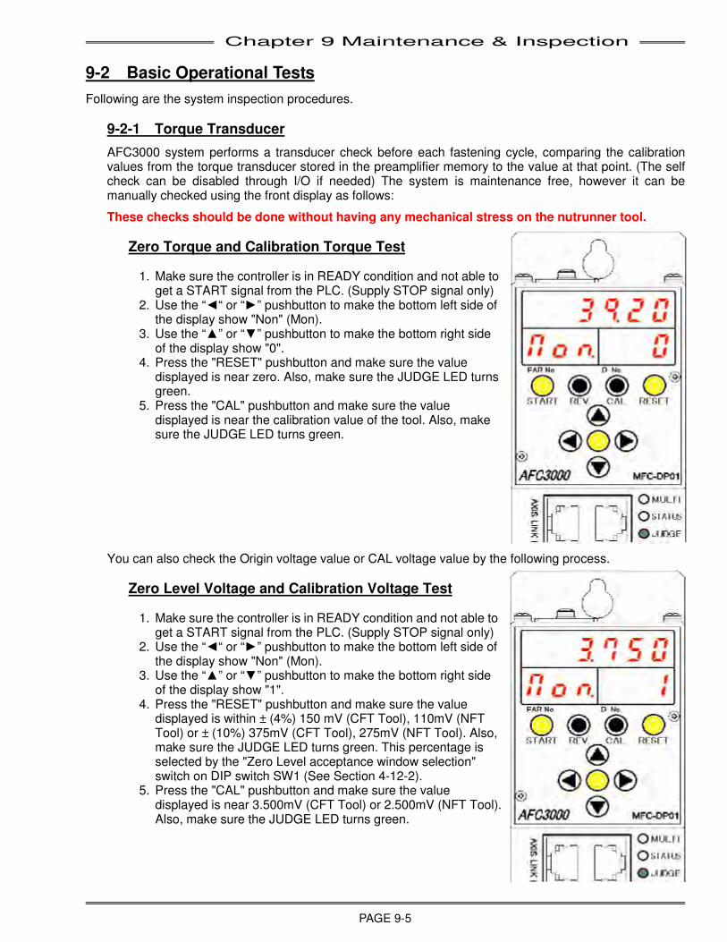
Chapter 9 Maintenance & Inspection
PAGE 9-5
9-2 Basic Operational Tests
Following are the system inspection procedures.
9-2-1 Torque Transducer
AFC3000 system performs a transducer check before each fastening cycle, comparing the calibration values from the torque transducer stored in the preamplifier memory to the value at that point. (The self check can be disabled through I/O if needed) The system is maintenance free, however it can be manually checked using the front display as follows:
These checks should be done without having any mechanical stress on the nutrunner tool.
Zero Torque and Calibration Torque Test
1. Make sure the controller is in READY condition and not able to get a START signal from the PLC. (Supply STOP signal only)
2. Use the “◄“ or “►” pushbutton to make the bottom left side of the display show "Non" (Mon).
3. Use the “▲” or “▼” pushbutton to make the bottom right side of the display show "0".
4. Press the "RESET" pushbutton and make sure the value displayed is near zero. Also, make sure the JUDGE LED turns green.
5. Press the "CAL" pushbutton and make sure the value displayed is near the calibration value of the tool. Also, make sure the JUDGE LED turns green.
You can also check the Origin voltage value or CAL voltage value by the following process.
Zero Level Voltage and Calibration Voltage Test
1. Make sure the controller is in READY condition and not able to get a START signal from the PLC. (Supply STOP signal only)
2. Use the “◄“ or “►” pushbutton to make the bottom left side of the display show "Non" (Mon).
3. Use the “▲” or “▼” pushbutton to make the bottom right side of the display show "1".
4. Press the "RESET" pushbutton and make sure the value displayed is within ± (4%) 150 mV (CFT Tool), 110mV (NFT Tool) or ± (10%) 375mV (CFT Tool), 275mV (NFT Tool). Also, make sure the JUDGE LED turns green. This percentage is selected by the "Zero Level acceptance window selection" switch on DIP switch SW1 (See Section 4-12-2).
5. Press the "CAL" pushbutton and make sure the value displayed is near 3.500mV (CFT Tool) or 2.500mV (NFT Tool). Also, make sure the JUDGE LED turns green.
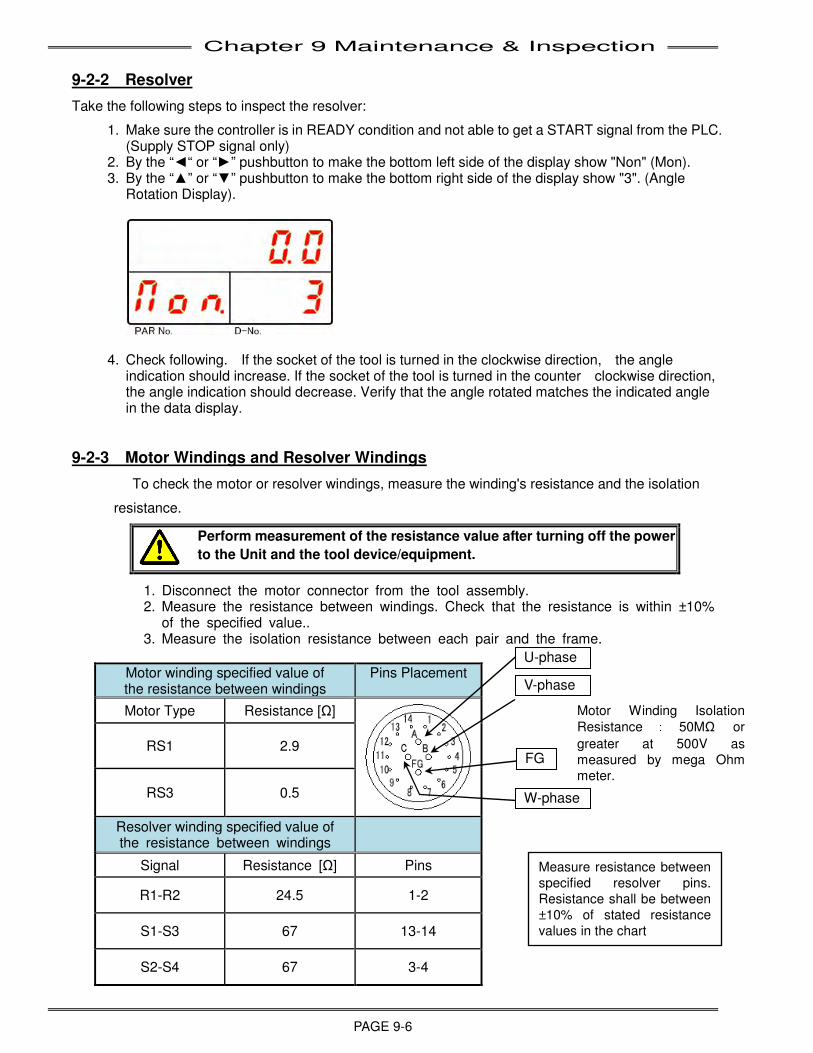
Chapter 9 Maintenance & Inspection
PAGE 9-6
9-2-2 Resolver
Take the following steps to inspect the resolver:
1. Make sure the controller is in READY condition and not able to get a START signal from the PLC. (Supply STOP signal only)
2. By the “◄“ or “►” pushbutton to make the bottom left side of the display show "Non" (Mon). 3. By the “▲” or “▼” pushbutton to make the bottom right side of the display show "3". (Angle
Rotation Display).
4. Check following. If the socket of the tool is turned in the clockwise direction, the angle indication should increase. If the socket of the tool is turned in the counter clockwise direction, the angle indication should decrease. Verify that the angle rotated matches the indicated angle in the data display.
9-2-3 Motor Windings and Resolver Windings
To check the motor or resolver windings, measure the winding's resistance and the isolation
resistance.
Perform measurement of the resistance value after turning off the power
to the Unit and the tool device/equipment.
1. Disconnect the motor connector from the tool assembly. 2. Measure the resistance between windings. Check that the resistance is within ±10%
of the specified value.. 3. Measure the isolation resistance between each pair and the frame.
Motor winding specified value of the resistance between windings
Pins Placement
Motor Type Resistance [Ω]
RS1 2.9
RS3 0.5
Resolver winding specified value of the resistance between windings
Signal Resistance [Ω] Pins
R1-R2 24.5 1-2
S1-S3 67 13-14
S2-S4 67 3-4
U-phase
V-phase
FG
W-phase
Motor Winding Isolation
Resistance : 50MΩ or
greater at 500V as
measured by mega Ohm
meter.
Measure resistance between
specified resolver pins.
Resistance shall be between
±10% of stated resistance
values in the chart
Chapter 9 Maintenance & Inspection
PAGE 9-7
9-3 Replacements
WARNING: DO NOT CONNECT OR DISCONNECT CABLES OR OTHER SYSTEM COMPONENTS WITH
POWER APPLIED. FOLLOW LOCKOUT/TAGOUT AND OTHER APPLICABLE SAFETY PRECAUTIONS.
NOTE: When replacing the AFC3000 System controller, ensure that the new unit is configured with the compatible Hardware and Firmware version as the unit being replaced. The Firmware Version number will show in the Data Display when the Parameter number displays “SYS” and the D-NO displays “001”. Newer firmware versions will provide compatibility with older firmware versions under most instances. When the system requires special firmware due to customer requirements, care should be taken to ensure Spare units are ordered with the Firmware version identified.
9-3-1 MFC Unit
Do not attempt to replace a component of the tool - the tool must be replaced as a complete assembly. When one MFC Unit is being replaced with another, it is important to verify that both units are the same type.
Unit Replacement Procedures
1. Verify the enclosure power is off. Ensure all cables connected to the MFC unit are clearly marked (for reconnection).
2. Disconnect all cables from the unit. 3. Loosen (do not remove) the three (3) screws that secure the MFC unit to the back panel. The
upper bracket of the MFC unit has one slotted hole and the bottom bracket has two open-ended slots.
4. Lift up and out on the unit to remove. 5. Verify the new MFC unit’s rotary address switches are set to the appropriate spindle number and
Special Function Switches SW1 and SW2 reflect the correct configuration (as the unit being replaced). Refer to Section 4-12.
6. Verify the MFC Units have the same configuration (hardware and software). 7. Install the new MFC unit in reverse order of removal. 8. Apply power to the enclosure. After approximately 7 seconds, the System will finalize the Power
On Self Test (POST). 9. The MFC unit WILL require re-entry of the preset data. Refer to Chapters 7 and 8.
Although the fastening parameters can be set from the display device on the unit, using the AFC3000 User Console can shorten the restoration time because the setting value can be written on the unit by using the fastening parameters setting file.
The following setting items are required to set manually. ・・・・Spindle No. Rotary Address Switches ・・・・Special Function SW1Switch::::No.8 “Communication Station Specifications” ・・・・Par No. “SYS”, D-No. “003” (System Indication)
Chapter 9 Maintenance & Inspection
PAGE 9-8
9-3-2 Tool
Do not attempt to replace a component of the tool - the tool must be replaced as a complete assembly. The tool type identification can be found on the identification tag affixed to the tool and on the System [TOOL TYPE] preset value.
Tool Replacement Procedures
1. Verify all System power is off. 2. Ensure that the homerun cable is marked for reconnection, then disconnect it from the tool. 3. Ensure the spindle assembly and nutrunner are supported, and remove the (3) bolts securing
them to the mounting plate. WARNING: These bolts also secure the nutrunner. Some tool models are very heavy. Use precautions when disconnecting, removing, and installing these components.
4. Follow all safety precautions to install an identical nutrunner assembly by performing the removal procedure in reverse order.

Chapter 10 Troubleshooting
PAGE 10-1
Chapter 10: Troubleshooting
10
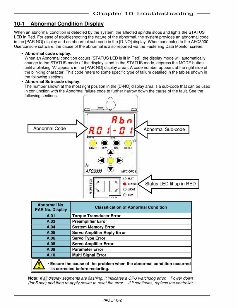
Chapter 10 Troubleshooting
PAGE 10-2
10-1 Abnormal Condition Display
When an abnormal condition is detected by the system, the affected spindle stops and lights the STATUS LED in Red. For ease of troubleshooting the nature of the abnormal, the system provides an abnormal code in the [PAR NO] display and an abnormal sub-code in the [D-NO] display. When connected to the AFC3000 Userconsole software, the cause of the abnormal is also reported via the Fastening Data Monitor screen.
wwww Abnormal code display. When an Abnormal condition occurs (STATUS LED is lit in Red), the display mode will automatically change to the STATUS mode (If the display is not in the STATUS mode, depress the MODE button until a blinking “A” appears in the [PAR NO] display area). A code number appears at the right side of the blinking character. This code refers to some specific type of failure detailed in the tables shown in the following sections.
w Abnormal Sub-code display. The number shown at the most right position in the [D-NO] display area is a sub-code that can be used in conjunction with the Abnormal failure code to further narrow down the cause of the fault. See the following sections.
Note: If all display segments are flashing, it indicates a CPU watchdog error. Power down (for 5 sec) and then re-apply power to reset the error. If it continues, replace the controller.
Abnormal No. PAR No. Display
Classification of Abnormal Condition
A.01 Torque Transducer Error
A.03 Preamplifier Error
A.04 System Memory Error
A.05 Servo Amplifier Reply Error
A.06 Servo Type Error
A.08 Servo Amplifier Error
A.09 Parameter Error
A.10 Multi Signal Error ・・・・Ensure the cause of the problem when the abnormal condition occurred
is corrected before restarting.
Status LED lit up in RED
Abnormal Code Abnormal Sub-code
Chapter 10 Troubleshooting
PAGE 10-3
10-2 Torque Transducer Errors [A.01 - *]
Torque Transducer Self-Check Function
• Code A01-01 – TORQUE TRANSDUCER / ZERO MASTER ERROR
The System detected a Zero Level Check error during power on initialization. CAUSE: • When the tool torque transducer is sensing excessive torque due to pressure on the tool body
during power on initialization (when tool normally should be in an idle state with no external forces applied)
• The tool cable is disconnected or lost connection during power on. • If the controller or the tool cable is located in an electric or magnetic noise field. • When the torque transducer, tool cable or the controller malfunctions. RECOVERY: 1. Check that the tool has no external force applied to it (IE: anything touching the tool assembly,
misalignment, etc.). Also verify there is no excessive friction in the spindle assembly. 2. Verify that no excessive vibration or shock takes place on the tool mounting at power on of the
controller. (Vibration could be sensed by torque transducer) 3. Verify that the tool cable is securely connected at both ends and free from cuts, abrasive wear or
kinks 4. Verify that the tool cable or controller are not located near any high voltage transient power
sources. Relocate as required and reinitialize. 5. Turn control power off to the unit for at least 5 seconds then re-apply power 6. Exchange tool cable, tool and/or controller with known working units. Reinitialize the system after
each exchange to determine which component may have caused the failure (abnormal). 7. Replace the defective component.
Automatic torque transducer ‘Self-Check’ is performed at controller power-up and at the input of the START signal (each cycle). This verifies proper torque transducer Zero / Full Scale Calibration voltage levels BEFORE fastening each cycle. (The self check is performed upon receiving the START signal and BEFORE the tool starts to rotate) Care must be taken that the tool assembly is stable, not moving or subject to shock / external forces during the Self-Check process which may result in improper Zero / Cal voltage level readings (transducer Zero / Cal abnormals may result - ABN code 01-01, 01-02, 01-03 or 01-04).
Chapter 10 Troubleshooting
PAGE 10-4
• Code A01-02 – TORQUE TRANSDUCER / CAL MASTER ERROR
The System detected a Calibration Voltage Check error during power on initialization. CAUSE: 1. When the tool torque transducer is sensing excessive torque due to pressure on the tool body
during power on initialization (when tool normally should be in an idle state with no external forces applied)
2. The tool cable is disconnected or lost connection during power on 3. If the controller or the tool cable is located in an electric or magnetic noise field. 4. When the torque transducer, tool cable or the controller malfunctions. RECOVERY: 1. Check that the tool has no external force applied to it (IE: anything touching the tool assembly,
misalignment, etc.). Also verify there is no excessive friction in the spindle adapter. 2. Verify that no excessive vibration or shock takes place on the tool mounting at power on of the
system. (Vibration could be sensed by torque transducer) 3. Verify that the tool cable is securely connected at both ends and free from cuts, abrasive wear or
kinks 4. Verify that the tool cable or controller are not located near any high voltage transient power
sources. Relocate as required and reinitialize. 5. Turn control power off to the unit for at least 5 seconds then re-apply power 6. Exchange tool cable, tool and/or controller with known working units. Reinitialize the system after
each exchange to determine which component may have caused the failure (abnormal). 7. Replace the defective component.
• Code A01-03 - TORQUE TRANSDUCER / ZERO CHECK ERROR
The System detected a Zero Voltage Level Check error after a fastening START was attempted. CAUSE: • When the tool torque transducer is sensing excessive torque due to pressure on the tool body
during a START signal to the controller (when tool normally should be in an idle state with no external forces applied)
• The tool cable is disconnected or lost connection while a START was attempted. • If the controller or the tool cable is located in an electric or magnetic noise field. • When the torque transducer, tool cable or the controller malfunctions. RECOVERY: 1. Check that the tool has no external force applied to it (IE: anything touching the tool assembly,
misalignment, etc.). Also verify there is no excessive friction in the spindle assembly. 2. Verify that no excessive vibration or shock takes place on the tool mounting at the same time the
START signal is given to the system. (Vibration could be sensed by torque transducer) 3. Verify that the tool cable is securely connected at both ends and free from cuts, abrasive wear or
kinks 4. Verify that the tool cable or controller are not located near any high voltage transient power
sources. Relocate as required and reinitialize. 5. Turn control power off to the unit for at least 5 seconds then re-apply power 6. Exchange tool cable, tool and/or controller with known working units. Reinitialize the system after
each exchange to determine which component may have caused the failure (abnormal). 7. Replace the defective component.
Chapter 10 Troubleshooting
PAGE 10-5
• Code A01-04 – TORQUE TRANSDUCER / CAL CHECK ERROR
The System detected a Calibration Voltage Check error after a fastening START was attempted CAUSE: • When the tool torque transducer is sensing excessive torque due to pressure on the tool body
during a START signal to the controller (when tool normally should be in an idle state with no external forces applied)
• The tool cable is disconnected or lost connection while a START was attempted. • If the controller or the tool cable is located in an electric or magnetic noise field. • When the torque transducer, tool cable or the controller malfunctions. RECOVERY: 1. Check that the tool has no external force applied to it (IE: anything touching the tool assembly,
misalignment, etc.). Also verify there is no excessive friction in the spindle assembly. 2. Verify that no excessive vibration or shock takes place on the tool mounting at the same time the
START signal is given to the system. (Vibration could be sensed by torque transducer) 3. Verify that the tool cable is securely connected at both ends and free from cuts, abrasive wear or
kinks 4. Verify that the tool cable or controller are not located near any high voltage transient power
sources. Relocate as required and reinitialize. 5. Turn control power off to the unit for at least 5 seconds then re-apply power 6. Exchange tool cable, tool and/or controller with known working units. Reinitialize the system after
each exchange to determine which component may have caused the failure (abnormal). 7. Replace the defective component.
• Code A01-05 – TORQUE TRANSDUCER / CAL JUDGMENT ERROR
The System detected a Calibration Voltage error after a fastening START was attempted with the Calibration Check function disabled. CAUSE: • When the tool torque transducer is sensing excessive torque due to pressure on the tool body
during a START signal to the controller (when tool normally should be in an idle state with no external forces applied)
• The tool cable is disconnected or lost connection while a START was attempted. • If the controller or the tool cable is located in an electric or magnetic noise field. • When the torque transducer, tool cable or the controller malfunctions.
RECOVERY: 1. Check that the tool has no external force applied to it (IE: anything touching the tool assembly,
misalignment, etc.). Also verify there is no excessive friction in the spindle assembly. 2. Verify that no excessive vibration or shock takes place on the tool mounting at the same time the
START signal is given to the system. (Vibration could be sensed by torque transducer) 3. Verify that the tool cable is securely connected at both ends and free from cuts, abrasive wear or
kinks 4. Verify that the tool cable or controller are not located near any high voltage transient power
sources. Relocate as required and reinitialize. 5. Turn control power off to the unit for at least 5 seconds then re-apply power 6. Exchange tool cable, tool and/or controller with known working units. Reinitialize the system after
each exchange to determine which component may have caused the failure (abnormal). 7. Replace the defective component.
Chapter 10 Troubleshooting
PAGE 10-6
• Code A01-06 – TORQUE TRANSDUCER / STARTED ON ZERO ERROR CONDITION
The START signal was input while a Zero Check Abnormal (Code A01_3) condition existed. RECOVERY: 1. Confirm the PLC logic disables the start signal during an existing abnormal condition or when not
ready. (An abnormal condition must be corrected and RESET before normal operation may begin)
2. Follow the ZERO CHECK ERROR abnormal help procedure.
• Code A01-07 – TORQUE TRANSDUCER / STARTED ON CAL ERROR CONDITION
The START signal was input while a Cal Check Error (Code A01_4) condition existed. RECOVERY: 1. Confirm the PLC logic disables the start signal during an existing abnormal condition or when
not ready. (An abnormal condition must be corrected and RESET before normal operation may begin)
2. Follow the CAL CHECK ERROR abnormal help procedure.
Chapter 10 Troubleshooting
PAGE 10-7
10-3 Preamplifier Errors [A.03 - *]
• Code A03-01 - PREAMPLIFIER / TOOL ID DATA ERROR
Data checksum error between the preamplifier and the MFC Unit. Tool ID Data is not reliable due to data error. CAUSE: 1. The tool cable has lost connection during data transmission. 2. If the controller or the tool cable is located in an electric or magnetic noise field. 3. When the torque transducer, tool cable or the controller malfunctions. 4. The TOOL ID data is corrupt or has been lost due to cable being disconnected with power on RECOVERY: 1. Verify that the cable or controller are not located near any high voltage transient power sources.
Relocate as required and reinitialize the system. 2. Turn control power off to the unit for at least 5 second then re-start. 3. Exchange tool cable, tool and/or controller with known working units. Reinitialize the system after
each exchange to determine which component may have caused the failure (abnormal). 4. Replace the defective component. 5. If TOOL ID data is missing or corrupt, replace tool and return to FEC to be re-programmed
(to see TOOL ID Data, use AFC3000 software to upload TOOL ID data and view contents “Details” – if any data is blank or missing, data may have been lost)
Note: The use of long cables and/or extension cables or installation in a high electrical noise area may increase the chance of this abnormal. In this case, the timing of the preamp monitoring may be changed for optimum performance in these cases. See 8-7-2 System Parameters [Data No. 53] setup.
• Code A03-02 - PREAMPLIFIER / TOOL TYPE ERROR
The connected tool type (Shown in System Parameter 100) does not match the tool type programmed into the controller (Shown in System Parameter 200). This error may occur when controllers or tools are replaced with the wrong type unit or the parameter program does not match the tool size installed. RECOVERY: 1. Verify the tool size (model number) matches the tool programmed in the controller parameter. 2. Program proper tool number into the controller (MFC) unit or change tool to proper tool. 3. Confirm TOOL ID data has not been corrupted or is missing – Reprogram TOOL ID or exchange
with new tool

Chapter 10 Troubleshooting
PAGE 10-8
• Code A03-03 - PREAMPLIFIER / TOOL IS NOT CONNECTED
Communications error between the tool preamplifier (torque transducer) and the controller. CAUSE: 1. The tool cable is not connected or has lost connection during communication. 2. If the controller or the transducer cable is located in an electric or magnetic noise field causing the
Tool ID not to be read correctly. 3. When the torque transducer, transducer cable or the controller malfunctions. RECOVERY: 1. Verify that the tool cable is securely connected at both ends and free from cuts, abrasive wear or
kinks 2. Verify that excessive strain is not being applied to the tool connector or cable while running. 3. Verify that the cable or controller are not located near any high voltage transient power sources.
Relocate as required and reinitialize the system. 4. Turn control power off to the unit for at least 5 seconds then re-start. 5. Confirm TOOL ID data has not been corrupted or is missing 6. Exchange tool cable, tool and/or controller with known working units. Reinitialize the system after
each exchange to determine which component may have caused the failure (abnormal). 7. Replace the defective component.
Note: The use of long cables and/or extension cables or installation in a high electrical noise area may increase the chance of this abnormal. In this case, the timing of the preamp monitoring may be changed for optimum performance in these cases. See 8-7-2 System Parameters [Data No. 53] setup.
10-4 System Memory Errors [A.04 - *]
• Code A04-01 - SYSTEM MEMORY ERROR / FLASH ROM WRITE ERROR
Communications error to internal MFC Unit Flash ROM during a WRITE attempt. CAUSE: 1. If the controller is located in an electric or magnetic noise field. 2. Flash ROM IC chip has malfunctioned. RECOVERY: 1. Verify that the controller is not located near any high voltage transient power sources. Relocate
as required and reinitialize the system. 2. Turn control power off to the unit for at least 5 seconds then re-apply power. 3. Replace controller.
• Code A04-02 - SYSTEM MEMORY ERROR / FLASH ROM READ ERROR
Communications error to internal MFC Unit Flash ROM during a READ attempt. CAUSE: 1. Corrupt memory data in the fieldbus configuration area or newly installed fieldbus module with no
(Fieldbus Setup) configuration 2. If the controller is located in an electric or magnetic noise field. 3. Flash ROM IC chip has malfunctioned. RECOVERY: 1. If fieldbus interface is used, configure and download fieldbus configuration. Cycle Power. 2. Verify that the controller is not located near any high voltage transient power sources. Relocate
as required and reinitialize the system. 3. Turn control power off to the unit for at least 5 seconds then re-apply power. 4. Replace controller.
Chapter 10 Troubleshooting
PAGE 10-9
• Code A04-03 - SYSTEM MEMORY ERROR / SERVO AMP FLASH ROM ERROR
Communications error to internal MFC Unit Servo Amp flash ROM. CAUSE: 1. If the controller is located in an electric or magnetic noise field. 2. Flash ROM IC chip has malfunctioned. RECOVERY: 1. Verify that the controller is not located near any high voltage transient power sources. Relocate
as required and reinitialize the system. 2. Turn control power off to the unit for at least 5 seconds then re-apply power. 3. Replace controller.
• Code A04-04 - SYSTEM MEMORY ERROR / STORED DATA WRITE ERROR
An error occurred during a WRITE attempt to SDRAM saved data. CAUSE: 1. If the controller is located in an electric or magnetic noise field. 2. SDRAM chip has malfunctioned. RECOVERY: 1. Verify that the controller is not located near any high voltage transient power sources. Relocate
as required and reinitialize the system. 2. Turn control power off to the unit for at least 5 seconds then re-apply power. 3. Replace controller. Note: The use of long cables and/or extension cables or installation in a high electrical noise area may increase the chance of this abnormal. In this case, the timing of the preamp monitoring may be changed for optimum performance in these cases. See 8-7-2 System Parameters Data No. 53 setup.
• Code A04-05 - SYSTEM MEMORY ERROR / STORED DATA READ ERROR
An error occured during a READ attempt from SDRAM saved data. CAUSE: 1. If the controller is located in an electric or magnetic noise field. 2. SDRAM chip has malfunctioned. RECOVERY: 1. Verify that the controller is not located near any high voltage transient power sources. Relocate
as required and reinitialize the system. 2. Turn control power off to the unit for at least 5 seconds then re-apply power. 3. Replace controller.
Chapter 10 Troubleshooting
PAGE 10-10
• Code A04-06 - SYSTEM MEMORY ERROR / RTC WRITE ERROR
An error occurred during a WRITE attempt to the Real-time Clock chip. CAUSE: 1. If the controller is located in an electric or magnetic noise field. 2. RTC chip has malfunctioned. RECOVERY: 1. Verify that the controller is not located near any high voltage transient power sources. Relocate
as required and reinitialize the system. 2. Turn control power off to the unit for at least 5 seconds then re-apply power. 3. Replace controller.
• Code A04-07 - SYSTEM MEMORY ERROR / RTC READ ERROR
An error occurred during a READ attempt from the Real-time Clock chip. CAUSE: 1. If the controller is located in an electric or magnetic noise field. 2. RTC chip has malfunctioned. RECOVERY: 1. Verify that the controller is not located near any high voltage transient power sources. Relocate
as required and reinitialize the system. 2. Turn control power off to the unit for at least 5 seconds then re-apply power. 3. Replace controller.
10-5 Servo Amplifier Reply Errors [A.05 - *]
• Code A05-01 - SERVO AMPLIFIER REPLY ERROR / NO REPLY FROM RESOLVER
The controller is attempting to turn the motor but is not receiving any signals back from the resolver to indicate that the tool is actually turning or the speed reference on the amplifier is not responding. CAUSE: 1. The tool cable is damaged or not connected. 2. When the resolver, motor or the controller malfunctions. 3. If there is excessive binding in the fastener, transmission or the spindle assembly keeping the
motor from turning. 4. System Parameter #523 (Fastening Current Limit) is not set to the correct value (may be too low). 5. Torque Transducer damage/error will not allow motor to start/turn. RECOVERY: 1. Verify that the tool cable is securely connected at both ends and free from cuts, abrasive wear or
kinks 2. Connect a known good spare tool cable to the existing tool. 3. Exchange tool and/or controller with known working units. Reinitialize the system after
exchanges. 4. Verify that System Parameter #523 [Fastening Current Limit] is set to the correct default value. (A
lower value than the default value will limit the current output of the controller to the value programmed)
5. Inspect and correct any binding in the spindle assembly, transmission or fasteners.
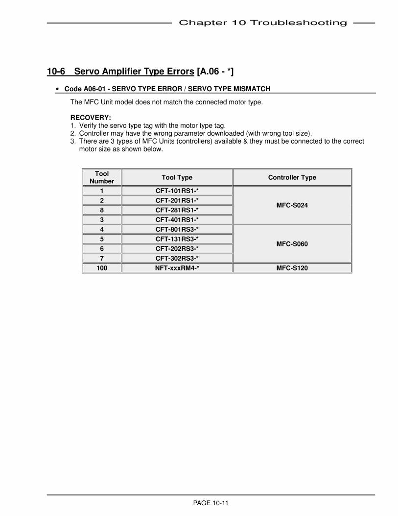
Chapter 10 Troubleshooting
PAGE 10-11
10-6 Servo Amplifier Type Errors [A.06 - *]
• Code A06-01 - SERVO TYPE ERROR / SERVO TYPE MISMATCH
The MFC Unit model does not match the connected motor type. RECOVERY: 1. Verify the servo type tag with the motor type tag. 2. Controller may have the wrong parameter downloaded (with wrong tool size). 3. There are 3 types of MFC Units (controllers) available & they must be connected to the correct
motor size as shown below.
Tool Number
Tool Type Controller Type
1 CFT-101RS1-*
MFC-S024 2 CFT-201RS1-*
8 CFT-281RS1-*
3 CFT-401RS1-*
4 CFT-801RS3-*
MFC-S060 5 CFT-131RS3-*
6 CFT-202RS3-*
7 CFT-302RS3-*
100 NFT-xxxRM4-* MFC-S120
Chapter 10 Troubleshooting
PAGE 10-12
10-7 Servo Amplifier Errors [A.08 - *]
• Code A08-01 - SERVO AMPLIFIER ERROR / SERVO HAS OVER HEATED
The MFC controller servo thermal sensor has detected an overheat condition. CAUSE: 1. If the environmental temperature is more than 113 degrees Fahrenheit (45 degree centigrade)
without any air flow or cooling unit 2. Source voltage is very close to the limit (253 VAC) and the environment temperature is also close
to 113 degrees F. 3. Maximum torque or duty cycle is being run or exceeded by the tool every cycle. (Duty can not be
more than 60% - time running/overall cycle time) RECOVERY: 1. Replace the controller. 2. Provide additional cooling to the enclosure. 3. Verify and correct the source voltage as required. 4. Turn control power off to the unit for at least 5 minutes then re-apply power. 5. Verify proper torque or work piece.
• Code A08-02 - SERVO AMPLIFIER ERROR / WATCHDOG TIMER ABNORMAL
The MFC controller watchdog timer is not functioning properly. CAUSE: 1. The controller watch dog circuit has malfunctioned or failed. RECOVERY: 1. Turn control power off to the unit for at least 5 seconds then re-apply power. 2. Replace the controller.
• Code A08-04 - SERVO AMPLIFIER ERROR / OVER CURRENT
The MFC controller servo circuit experienced a current overload. CAUSE: 1. The fastener rundown speed may be set too high and creating high current spikes when it tries to
ramp down to a slower speed or as the fastener is seated to the work piece. 2. Damage to the motor power wiring of the tool cable causing a short circuit. 3. Damage to the resolver wiring of the tool cable resulting in the servo amplifier loosing control of
the motor because the signal feedback is incorrect. RECOVERY: 1. Reduce fastener rundown speed or reduce the difference between the fastener rundown speed
and ramp down speed. 2. Verify that rundown revolutions is not set too high. 3. Verify that the cable is not damaged. Replace if necessary.
Chapter 10 Troubleshooting
PAGE 10-13
• Code A08-05 - SERVO AMPLIFIER ERROR / OVER VOLTAGE ABNORMAL
The MFC controller servo power supply circuit is not working properly or the input voltage is above the maximum limit. CAUSE: 1. The controller internal power supply has failed. 2. Source voltage is very close to the limit (253 VAC). 3. Internal regenerative voltage surge caused by motor ramp down. RECOVERY: 1. Replace the controller. 2. Verify and correct the source voltage as required. 3. Reduce fastener rundown speed or reduce the difference between the fastener rundown speed
and ramp down speed. 4. Verify that rundown revolutions is not set too high (causing fastener to ‘slam’ into part before
slowing down) 5. Verify that the cable is not damaged. Replace if necessary.
• Code A08-06 - SERVO AMPLIFIER ERROR / SOURCE VOLTAGE ABNORMAL
The MFC controller control power supply circuit has detected improper input power voltage either above or below the specified limits. CAUSE: 1. The controller internal control power circuit has failed. 2. Source voltage is out of the limit (24VDC +/-10%) and/or unstable. RECOVERY: 1. Replace the controller. 2. Check the control power connections. 3. Verify and correct the source voltage as required.
• Code A08-07 - SERVO AMPLIFIER ERROR / CONTROL POWER INTERRUPT ABNORMAL
The MFC controller control power circuit has detected input voltage below 18V. CAUSE: 1. The control power supply (24VDC) does not have enough capacity. RECOVERY: 1. Confirm power supply wiring 2. Change control power supply to a larger size.
• Code A08-08 - SERVO AMPLIFIER ERROR / OVER SPEED.
The resolver signal received at the MFC controller indicates an over speed condition. CAUSE: 1. The tool cable or resolver has failed. RECOVERY: 1. Check resolver using method in 9-2-2. 2. Verify that the tool cable is securely connected at both ends and free from cuts, abrasive wear or
kinks. Replace tool cable with known good spare cable. 3. Replace tool assembly. 4. Replace the controller.
Chapter 10 Troubleshooting
PAGE 10-14
• Code A08-10 - SERVO AMPLIFIER ERROR / OVER LOAD (I SQUARE T)
The servo amplifier has detected that the motor has drawn too much current over a predefined period and has over loaded. CAUSE: 1. The duty cycle of the fastening application is too severe for this size of tool or for the parameters
currently set up. 2. The servo amplifier is not getting proper feedback from the resolver and supplying extra current to
the motor. RECOVERY: 1. Reduce duty cycle - Increase tool “downtime or off time” and/or increase 1st,2nd and 3rd Speeds to
reduce the amount of time running at high torque/slow speed. 2. Increase the Ramp Down Start Torque, 1st Torque or 2nd Torque at which 1st Speed shifts to 2nd
Speed. 3. If using Torque Recovery, try decreasing the recovery time. 4. Check the fastening joint. If it is a soft joint (increased angular turn) increase 1st Torque and/or
2nd Torque and speeds to keep motor from running slow (under load) for long durations 5. Check the cable connections. 6. If the problem remains, a larger tool assembly may be required for this application. Please contact
FEC.
• Code A08-11 - SERVO AMPLIFIER ERROR / RESOLVER SIGNAL ERROR
The resolver signal received from the tool in the controller is not correct. RECOVERY: 1. Verify that the tool cable is securely connected at both ends and free from cuts, abrasive wear or
kinks. Replace tool cable with known good spare cable. 2. Confirm tool duty is below 60% and/or motor temp is below 70 degree C (158degree F) 3. Replace the tool. 4. Replace the controller
• Code A08-12 - SERVO AMPLIFIER ERROR / SYSTEM ERROR
An internal system error has occurred. RECOVERY:
1. Replace the controller.
• Code A08-14 - SERVO AMPLIFIER ERROR / MOTOR PARAMETER ERROR
The internal motor parameters in the MFC Unit are abnormal or not correct for the tool. RECOVERY: 1. Replace the controller.
• Code A08-15 - SERVO AMPLIFIER ERROR / SYSTEM ERROR
An internal system error has occured. RECOVERY: 1. Replace the controller.
Chapter 10 Troubleshooting
PAGE 10-15
• Code A08-16 - SERVO AMPLIFIER ERROR / MOTOR DRIVE POWER VOLTAGE ERROR
The motor three phase AC input power to the MFC Unit is disconnected or was turned off during fastening. CAUSE: 1. The controller internal power supply has failed. 2. The input power cable is not connected or is damaged. 3. Source voltage is out of the limit (180-253 VAC 3 phase). 4. One or more phases of input power are missing. RECOVERY: 1. Verify that the input power cable is connected and not damaged. 2. Verify and correct the source voltage as required (on all three phases) 3. Verify whether the transformer is sized correctly 4. Replace the controller.
• Code A08-17 - SERVO AMPLIFIER ERROR / SYSTEM CPU ERR
The controller has detected a failure of the Servo CPU CAUSE:
1. The Servo CPU has failed RECOVERY:
1. Replace the controller
• Code A08-20 - SERVO AMPLIFIER ERROR / CURRENT SENSOR ERROR
The controller has detected a failure of the Servo Current Sensor CAUSE:
1. The Servo Current Sensor has failed. RECOVERY:
1. Replace the controller
• Code A08-21 - SERVO AMPLIFIER ERROR / MOTOR HUNTING DETECTION ERROR
Motor oscillation is detected during fastening (detects CCW rotation during CW command and vice versa). This function added at firmware version 1.417
CAUSE:
1. Deterioration of the servo isolation amplifier circuit due to use, duty and heat over a long period of time (typically more than 15yrs.) may cause sensing of incorrect motor current draw which leads to larger torque scatter and accuracy variance (greater than controller specified accuracy)
2. Tool mounting may be loose, long spindles / extensions or external gearing (with large ‘wind-up’ causing backlash at high torques) are used
RECOVERY:
1. Turn off power to the controller for at least 5 seconds, then re-apply power.
2. Confirm tool mounting bolts are tight.
3. Adjust system parmeter (054) higher until abnormal condition ends (if caused by #2 above)
4. Replace the controller if fault continues.
Note: Limit value for this detection is set in System Parameter “SYS_054”. Factory set value is 25000.
Chapter 10 Troubleshooting
PAGE 10-16
Can be adjusted up to 999999 if false alarms are occurring. See 8-4-3 for system parm. setting method.
• Code A08-24 - SERVO AMPLIFIER ERROR / SYSTEM ERROR
The controller has detected a failure of the Servo CAUSE:
2. Internal failure of the controller has occured RECOVERY:
2. Replace the controller
10-8 Parameter Errors [A.09 - *]
• Code A09-02, A09-03, A09-04, A09-05- PARAMETER ERROR / MISSING PARAMETER SETUP
Some parameter settings are missing, set to “0” or out of the specified range of the tool. RECOVERY: 1. Check that the parameter presets are not set as <0> or out of the specified range of the tool.
Confirm and set the affected value(s) in the acceptable range A09-02: 100: Calibration Torque 102: Peak Torque High Limit
103: Target Torque (when Fastening Method is Torque Control) A09-03: 201: Final Angle High Limit
202: Target Angle (when Fastening Method is Angle Control) A09-04: 312: 1st Time High Limit
314: 2nd Time Tigh Limit A09-05: 400, 401, 402, 403, 404, 409: Speed setting out of range
• Code A09-08 - PARAMETER ERROR / REVERSE TORQUE OVER.
The torque value exceeds the Reverse Torque High Limit value during a reverse operation. RECOVERY: 1. Verify that the programmed parameter value is correct. [D-No. 110] 2. If the value is correct, check the application. The size of the tool may not be adequate for this
application or the fastener being reversed may be over-torqued. 3. Verify there is no excessive binding in the fastener, transmission or the spindle assembly
keeping the motor from turning.
• Code A09-09 - PARAMETER ERROR / AXIS NUMBER SETTING ERROR.
The spindle address of the MFC Unit has been set as either 0 or 33~99. RECOVERY: 1. Remove the display device on the front of the MFC Unit and verify that the Unit Address rotary
switch is set to a valid address (1 through 32).
Chapter 10 Troubleshooting
PAGE 10-17
10-9 Multi Signal Errors [A.10 - *]
• Code A10-01 – SEQUENCE SELECT ERROR
System detected that the sequence number selected by the PLC is invalid when the start signal or manual reverse signal was applied. RECOVERY: 1. Check the sequence number selected by the PLC. The System uses two different ways of
selecting the sequence number: a. Binary Input.
If the "USE INDIVIDUAL SEQUENCE SELECT" bit (bit 11) is turned off, the system uses the combination of SEQUENCE SELECT BIT 0 ~ 4 for selecting sequence program between 1 ~ 32.
b. Individual Sequence Select Input. If the "USE INDIVIDUAL SEQUENCE SELECT" bit (bit 11) is turned on, the system uses individual sequence select signals (bit 16 ~ 47) for selecting sequence program 1 ~ 32. If none of these bits are turned on or more than two bits are turned on when the start signal or manual reverse signal is turned on, this error will occur.
• Code A10-02 – SPINDLE NOT FOUND ERROR
• The system received a START signal or Manual REVERSE signal while the Axis Link cable was disconnected.
• The system did not receive a reply from the spindle (Axis) specified in the sequence program when the system started a fastening cycle.
RECOVERY: 1. Check the communication cable between spindles. 2. Make sure all connected spindles can be found during a spindle search in the AFC3000 User
Console Software. 3. Confirm Ready status in the PLC for all connected spindles before issuing a START or Manual
REVERSE.
• Code A10-03 – SEQUENCE ERROR
The System lost communication with the spindle (axis) during the fastening cycle. RECOVERY: 1. Check the communication cable(s) between spindles are connected. 2. Confirm the Axis Link terminators are installed in the first and last spindles on the link. (See 3-16)
Chapter 10 Troubleshooting
PAGE 10-18
• Code A10-04 – MISSING SPINDLE SELECT IN SEQUENCE
The selected sequence program does not have a spindle (axis) number specified. RECOVERY: 1. Verify that the Selected sequence has a spindle specified. 2. Check the sequence number selected by the PLC. The System use two different ways of
selecting the sequence number: a. Binary Input.
If the "USE INDIVIDUAL SEQUENCE SELECT" bit (bit 11) is turned off, the system uses the combination of SEQUENCE SELECT BIT 0 ~ 4 for selecting sequence program between 1 ~ 32.
b. Individual Sequence Select Input. If the "USE INDIVIDUAL SEQUENCE SELECT" bit (bit 11) is turned on, the system uses individual sequence select signals (bit 16 ~ 47) for selecting sequence program 1 ~ 32. If none of these bits are turned on or more than two bits are turned on when the start signal or manual reverse signal is turned on, this error will occur.
• Code A10-05 – SEQUENCE IS NOT PROGRAMMED
The selected Sequence program was blank. RECOVERY: 1. Verify that a program exists for the Sequence selected. (Upload sequence and verify) 2. Check the sequence number selected by the PLC. The System use two different ways of
selecting the sequence number: a. Binary Input.
If the "USE INDIVIDUAL SEQUENCE SELECT" bit (bit 11) is turned off, the system uses the combination of SEQUENCE SELECT BIT 0 ~ 4 for selecting sequence program between 1 ~ 32.
b. Individual Sequence Select Input. If the "USE INDIVIDUAL SEQUENCE SELECT" bit (bit 11) is turned on, the system uses individual sequence select signals (bit 16 ~ 47) for selecting sequence program 1 ~ 32. If none of these bits are turned on or more than two bits are turned on when the start signal or manual reverse signal is turned on, this error will occur.
• Code A10-06 – SEQUENCE SETUP ERROR
An error was found in the fastening sequence program during execution of the sequence and/or Axis Link Cable connection is unstable during fastening. RECOVERY: 1. Upload suspect fastening sequence from the controller to the AFC3000 software. Run
‘Sequence Check’. Correct any errors found from Sequence Check and download back to controller.
2. If error persists, check the Axis Link cable connection as each controller. (Unplug and then plug back in to confirm seated and locked in)
• Code A10-8 – MOTOR POWER LOSS DETECTED
The system has detected the loss of motor power (3 phase) in the spindle selected by the sequence program during the fastening sequence or manual reverse operation RECOVERY: 1. Confirm the motor cables are connected / operating properly 2. Check the 3 phase motor power input for all spindles (Voltage between 200 – 230VAC) 3. Confirm capacity of motor power supply transformer (power is not dropping during cycle)
Chapter 10 Troubleshooting
PAGE 10-19
• Code A10-9 – AXIS LINK COMMUNICATION CONTROL ERROR
A Communication error has been detected on the Axis Communication link. 1. Controller configured as “SINGLE” is mixed within the “MULTI” configured spindles. (Occurs from firmware ver. 1.039 – 1.300) 2. The MASTER spindle was unable to read data sent from the SLAVE spindle(s). Controller firmware versions are mixed in the multi-spindle system.
RECOVERY: 1. Confirm spindles system parameter D-No. 3 is set as “MULTI” system and not “SINGLE” system. (refer to 8-5 in this manual for this setup) 2. Confirm the Axis Link cables between spindles and terminators are in place on first and last spindles. 3. Confirm all spindles have compatible version firmware. (all controller firmware must be <1.400 or all controller firmware must be 1.400 or greater within all the connected controllers) If there is a mix of this firmware, then change the controller(s) that is not compatible in the mix. (or see note below) 4. Check that all consecutive spindle numbers are set correctly (Rotary Switch) with no overlap 5. Skip a controller from the Axis Link (one at a time) to determine which controller is causing the communication error 6. Replace the suspect controller with spare Note: If firmware versions 1.400 or greater and a version <1.283 is mixed in the Multi-system, you
can disable the ‘Communication Check’ by turning “ON” DIP switch SW2-5 in the controllers with
version 1.400 or greater. This will disable the check until the firmware issue can be remedied (all
(old version) controller(s) used or controller(s) changed to a version 1.400 or greater)
In older firmware, this will occur in ver. <1.038 and ver. 1.214 or higher
• Code A10-10 – AXIS LINK COMMUNICATION OPERATION ERROR
Error detected from the data transmitted from a SLAVE spindle. The sequence step specified to be used for fastening and the fastening data reported after the step is complete, (parameter numbers) do not match in one or more of the (connected) spindle controllers. RECOVERY: 1. Check the Axis Link communication cable(s) between spindles. 2. Confirm the Axis Link Terminators are in place on first and last spindles. 3. Check that all consecutive spindle numbers are set correctly (Spindle number Rotary Switch) and there is no overlap. 4. Skip a controller from the Axis Link connection (one at a time) to determine which controller is causing the error (Replace the suspect controller) 5. Check that motor cables do not exceed maximum length (100feet) (shorten cables or add noise protection if necessary) 6. Check that controller power cables do not exceed (30feet) (shorten cable(s) or add noise protection if necessary) 7. Replace the suspect controller with spare
• Code A10-11 – AXIS LINK COMMUNICATION DISCONNECTION
Communication between spindle controllers has been disconnected. RECOVERY: 1. Check the Axis Link communication cable(s) between spindles – unplug and re-seat until connector ‘clicks’ (locks) in. 2. Confirm the Axis Link Terminators are in place on first and last spindles. 3. Replace suspect bad cable with new.
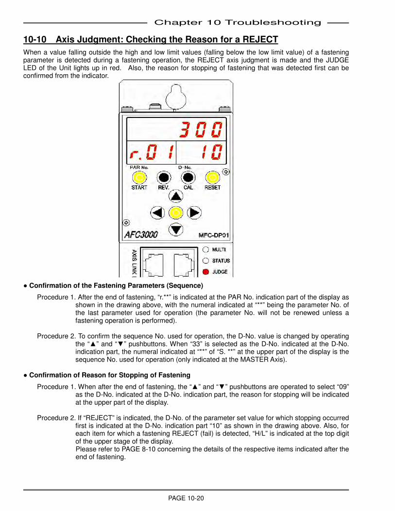
Chapter 10 Troubleshooting
PAGE 10-20
10-10 Axis Judgment: Checking the Reason for a REJECT
When a value falling outside the high and low limit values (falling below the low limit value) of a fastening parameter is detected during a fastening operation, the REJECT axis judgment is made and the JUDGE LED of the Unit lights up in red. Also, the reason for stopping of fastening that was detected first can be confirmed from the indicator.
● Confirmation of the Fastening Parameters (Sequence)
Procedure 1. After the end of fastening, “r.**” is indicated at the PAR No. indication part of the display as shown in the drawing above, with the numeral indicated at “**” being the parameter No. of the last parameter used for operation (the parameter No. will not be renewed unless a fastening operation is performed).
Procedure 2. To confirm the sequence No. used for operation, the D-No. value is changed by operating
the “▲” and “▼” pushbuttons. When “33” is selected as the D-No. indicated at the D-No. indication part, the numeral indicated at “**” of “S. **” at the upper part of the display is the sequence No. used for operation (only indicated at the MASTER Axis).
● Confirmation of Reason for Stopping of Fastening
Procedure 1. When after the end of fastening, the “▲” and “▼” pushbuttons are operated to select “09” as the D-No. indicated at the D-No. indication part, the reason for stopping will be indicated at the upper part of the display.
Procedure 2. If “REJECT” is indicated, the D-No. of the parameter set value for which stopping occurred
first is indicated at the D-No. indication part “10” as shown in the drawing above. Also, for each item for which a fastening REJECT (fail) is detected, “H/L” is indicated at the top digit of the upper stage of the display. Please refer to PAGE 8-10 concerning the details of the respective items indicated after the end of fastening.
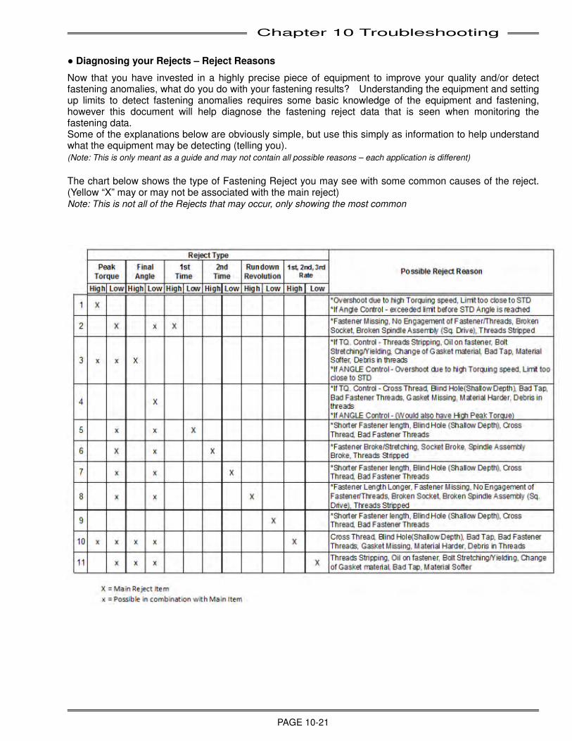
Chapter 10 Troubleshooting
PAGE 10-21
● Diagnosing your Rejects – Reject Reasons
Now that you have invested in a highly precise piece of equipment to improve your quality and/or detect fastening anomalies, what do you do with your fastening results? Understanding the equipment and setting up limits to detect fastening anomalies requires some basic knowledge of the equipment and fastening, however this document will help diagnose the fastening reject data that is seen when monitoring the fastening data. Some of the explanations below are obviously simple, but use this simply as information to help understand what the equipment may be detecting (telling you). (Note: This is only meant as a guide and may not contain all possible reasons – each application is different)
The chart below shows the type of Fastening Reject you may see with some common causes of the reject. (Yellow “X” may or may not be associated with the main reject) Note: This is not all of the Rejects that may occur, only showing the most common
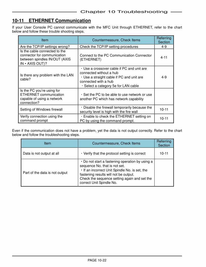
Chapter 10 Troubleshooting
PAGE 10-22
10-11 ETHERNET Communication
If your User Console PC cannot communicate with the MFC Unit through ETHERNET, refer to the chart below and follow these trouble shooting steps.
Item Countermeasure, Check Items Referring Section
Are the TCP/IP settings wrong? Check the TCP/IP setting procedures 4-9
Is the cable connected to the connector for communication between spindles IN/OUT (AXIS
IN・AXIS OUT)?
Connect to the PC Communication Connector (ETHERNET)
4-11
Is there any problem with the LAN cable?
・Use a crossover cable if PC and unit are
connected without a hub ・Use a straight cable if PC and unit are
connected with a hub ・Select a category 5e for LAN cable
4-9
Is the PC you’re using for ETHERNET communication capable of using a network connection?
・Set the PC to be able to use network or use
another PC which has network capability
Setting of Windows firewall ・Disable the firewall temporarily because the
security level is high with the fire wall 10-11
Verify connection using the command prompt
・Enable to check the ETHERNET setting on
PC by using the command prompt. 10-11
Even if the communication does not have a problem, yet the data is not output correctly. Refer to the chart below and follow the troubleshooting steps.
Item Countermeasure, Check Items Referring Section
Data is not output at all ・Verify that the protocol setting is correct 10-11
Part of the data is not output
・Do not start a fastening operation by using a
sequence No. that is not set. ・If an incorrect Unit Spindle No. is set, the
fastening results will not be output. Check the sequence setting again and set the correct Unit Spindle No.
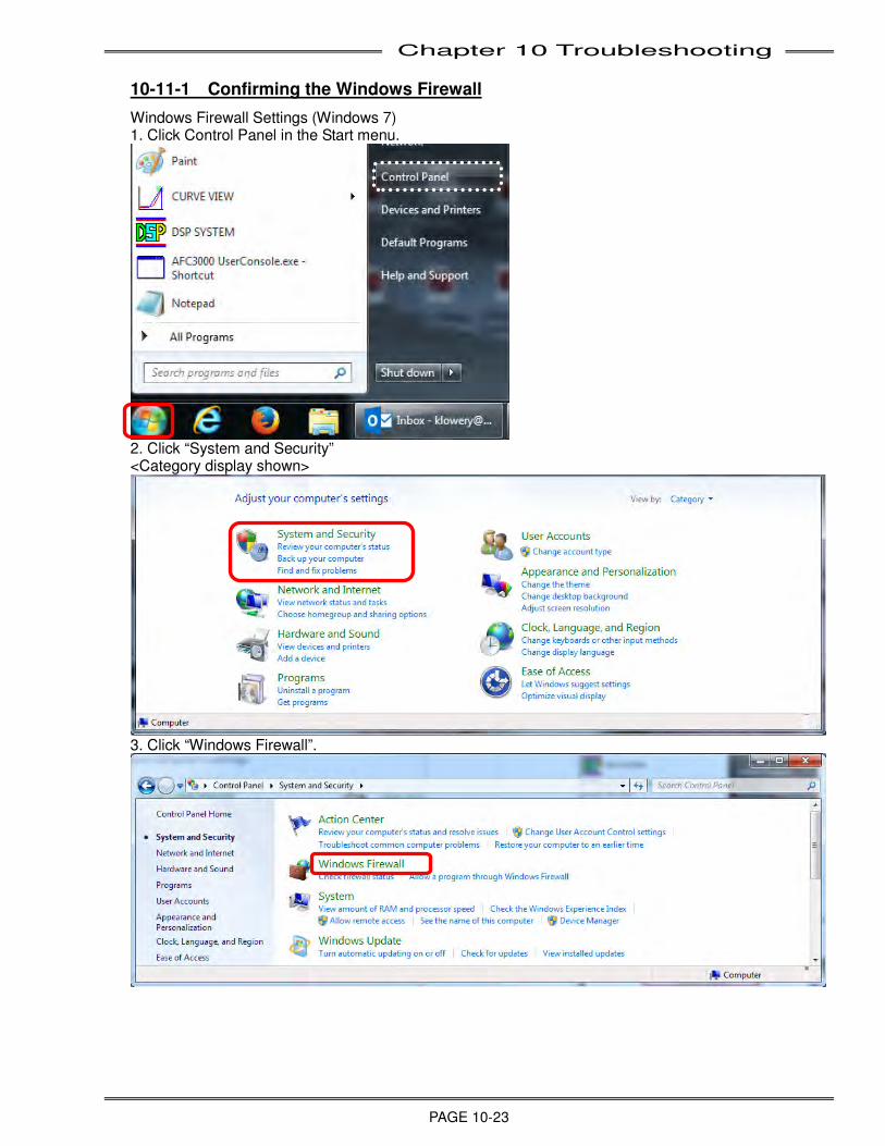
Chapter 10 Troubleshooting
PAGE 10-23
10-11-1 Confirming the Windows Firewall
Windows Firewall Settings (Windows 7) 1. Click Control Panel in the Start menu.
2. Click “System and Security” <Category display shown>
3. Click “Windows Firewall”.
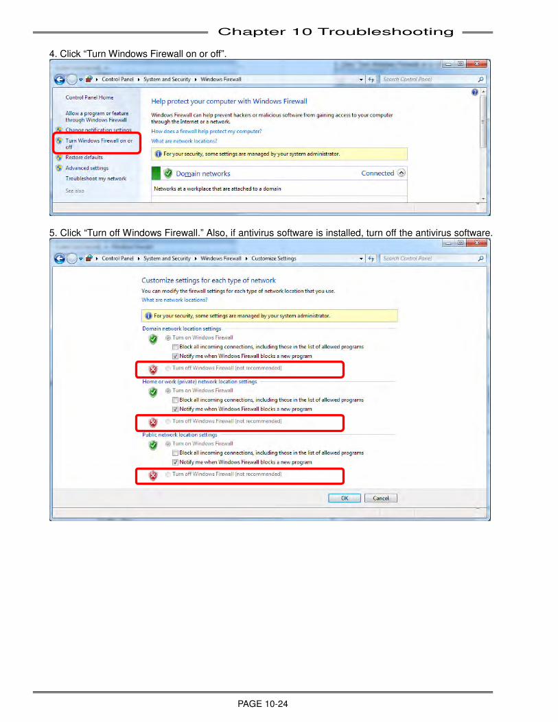
Chapter 10 Troubleshooting
PAGE 10-24
4. Click “Turn Windows Firewall on or off”.
5. Click “Turn off Windows Firewall.” Also, if antivirus software is installed, turn off the antivirus software.
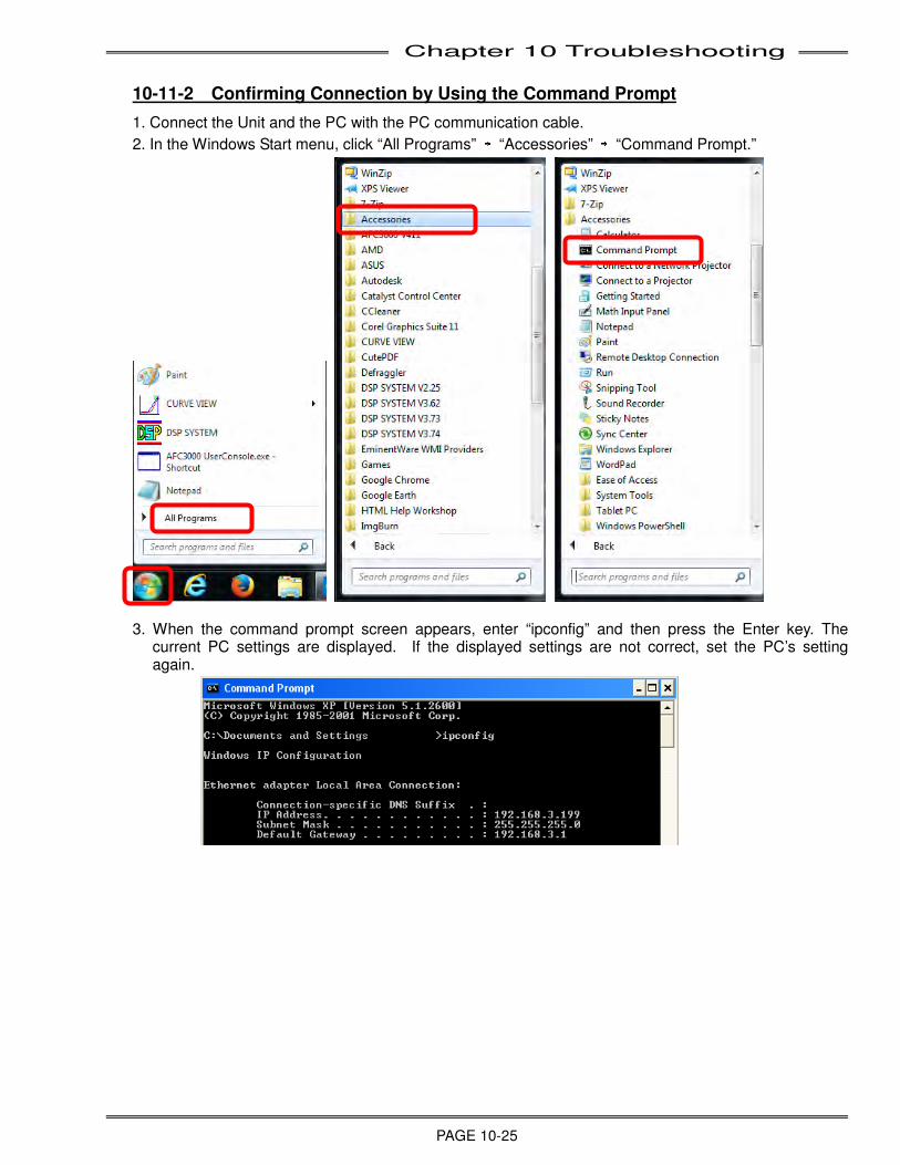
Chapter 10 Troubleshooting
PAGE 10-25
10-11-2 Confirming Connection by Using the Command Prompt
1. Connect the Unit and the PC with the PC communication cable.
2. In the Windows Start menu, click “All Programs” → “Accessories” → “Command Prompt.”
3. When the command prompt screen appears, enter “ipconfig” and then press the Enter key. The current PC settings are displayed. If the displayed settings are not correct, set the PC’s setting again.
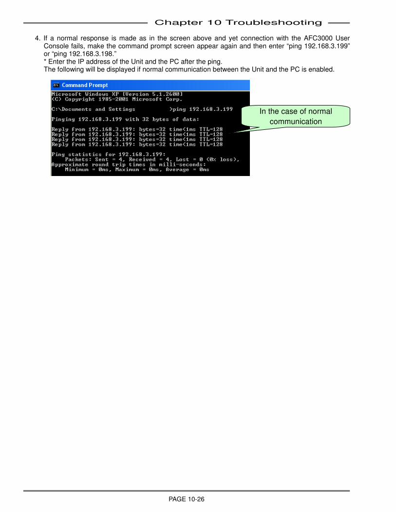
Chapter 10 Troubleshooting
PAGE 10-26
4. If a normal response is made as in the screen above and yet connection with the AFC3000 User
Console fails, make the command prompt screen appear again and then enter “ping 192.168.3.199” or “ping 192.168.3.198.” * Enter the IP address of the Unit and the PC after the ping. The following will be displayed if normal communication between the Unit and the PC is enabled.
In the case of normal
communication
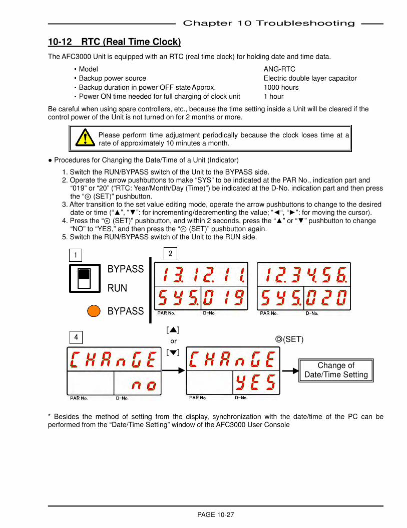
Chapter 10 Troubleshooting
PAGE 10-27
10-12 RTC (Real Time Clock)
The AFC3000 Unit is equipped with an RTC (real time clock) for holding date and time data. ・Model ANG-RTC
・Backup power source Electric double layer capacitor ・Backup duration in power OFF state Approx. 1000 hours ・Power ON time needed for full charging of clock unit 1 hour
Be careful when using spare controllers, etc., because the time setting inside a Unit will be cleared if the control power of the Unit is not turned on for 2 months or more.
Please perform time adjustment periodically because the clock loses time at a rate of approximately 10 minutes a month.
● Procedures for Changing the Date/Time of a Unit (Indicator)
1. Switch the RUN/BYPASS switch of the Unit to the BYPASS side. 2. Operate the arrow pushbuttons to make “SYS” to be indicated at the PAR No., indication part and
“019” or “20” (“RTC: Year/Month/Day (Time)”) be indicated at the D-No. indication part and then press the “⊚ (SET)” pushbutton.
3. After transition to the set value editing mode, operate the arrow pushbuttons to change to the desired date or time (“▲”, “▼”: for incrementing/decrementing the value; “◄“, “►”: for moving the cursor).
4. Press the “⊚ (SET)” pushbutton, and within 2 seconds, press the “▲” or “▼” pushbutton to change “NO” to “YES,” and then press the “⊚ (SET)” pushbutton again.
5. Switch the RUN/BYPASS switch of the Unit to the RUN side.
* Besides the method of setting from the display, synchronization with the date/time of the PC can be performed from the “Date/Time Setting” window of the AFC3000 User Console
[ ]
or
[ ]
4
1
Change of Date/Time Setting
◎(SET)
2

Chapter 10 Troubleshooting
PAGE 10-28
(Blank Page)