Embed Size (px)
Citation preview
Hardware Product Guide
McAfee® Firewall Enterprisemodels S4016, S5032, S6032, and S7032
2 McAfee® Firewall Enterprise S4016, S5032, S6032, and S7032 Hardware Product Guide
COPYRIGHTCopyright © 2011 McAfee, Inc. All Rights Reserved.
No part of this publication may be reproduced, transmitted, transcribed, stored in a retrieval system, or translated into any language in any form or by any means without the written permission of McAfee, Inc., or its suppliers or affiliate companies.
TRADEMARK ATTRIBUTIONSMcAfee®, the McAfee logo, Avert, ePO, ePolicy Orchestrator, Foundstone, Global Threat Intelligence, GroupShield, IntruShield, LinuxShield, MAX (McAfee SecurityAlliance Exchange), NetShield, PortalShield, Preventsys, SecureOS, SecurityAlliance, SiteAdvisor, SmartFilter, Total Protection, Type Enforcement, VirusScan, and WebShield are registered trademarks or trademarks of McAfee, Inc. or its subsidiaries in the United States and other countries.
LICENSE INFORMATION
License AgreementNOTICE TO ALL USERS: CAREFULLY READ THE APPROPRIATE LEGAL AGREEMENT CORRESPONDING TO THE LICENSE YOU PURCHASED, WHICH SETS FORTH THE GENERAL TERMS AND CONDITIONS FOR THE USE OF THE LICENSED SOFTWARE. IF YOU DO NOT KNOW WHICH TYPE OF LICENSE YOU HAVE ACQUIRED, PLEASE CONSULT THE SALES AND OTHER RELATED LICENSE GRANTOR PURCHASE ORDER DOCUMENTS THAT ACCOMPANIES YOUR SOFTWARE PACKAGING OR THAT YOU HAVE RECEIVED SEPARATELY AS PART OF THE PURCHASE (AS A BOOKLET, A FILE ON THE PRODUCT CD, OR A FILE AVAILABLE ON THE WEBSITE FROM WHICH YOU DOWNLOADED THE SOFTWARE PACKAGE). IF YOU DO NOT AGREE TO ALL OF THE TERMS SET FORTH IN THE AGREEMENT, DO NOT INSTALL THE SOFTWARE. IF APPLICABLE, YOU MAY RETURN THE PRODUCT TO MCAFEE OR THE PLACE OF PURCHASE FOR A FULL REFUND.
Contents
Preface 5About this guide . . . . . . . . . . . . . . . . . . . . . . . . . . . . . . . . . . . . . . . . . . . . . . . . . . . . . . . . . . . . .5
Audience . . . . . . . . . . . . . . . . . . . . . . . . . . . . . . . . . . . . . . . . . . . . . . . . . . . . . . . . . . . . . . . .5Conventions . . . . . . . . . . . . . . . . . . . . . . . . . . . . . . . . . . . . . . . . . . . . . . . . . . . . . . . . . . . . . .5Acronyms . . . . . . . . . . . . . . . . . . . . . . . . . . . . . . . . . . . . . . . . . . . . . . . . . . . . . . . . . . . . . . .6
Find product information . . . . . . . . . . . . . . . . . . . . . . . . . . . . . . . . . . . . . . . . . . . . . . . . . . . . . . .6
1 Introducing the appliances 7About the models . . . . . . . . . . . . . . . . . . . . . . . . . . . . . . . . . . . . . . . . . . . . . . . . . . . . . . . . . . . .7
Model S4016 . . . . . . . . . . . . . . . . . . . . . . . . . . . . . . . . . . . . . . . . . . . . . . . . . . . . . . . . . . . . .8Models S5032, S6032, and S7032 . . . . . . . . . . . . . . . . . . . . . . . . . . . . . . . . . . . . . . . . . . . . . .9
Software support . . . . . . . . . . . . . . . . . . . . . . . . . . . . . . . . . . . . . . . . . . . . . . . . . . . . . . . . . . . . .9Network ports . . . . . . . . . . . . . . . . . . . . . . . . . . . . . . . . . . . . . . . . . . . . . . . . . . . . . . . . . . . . . .10
Network modules . . . . . . . . . . . . . . . . . . . . . . . . . . . . . . . . . . . . . . . . . . . . . . . . . . . . . . . . .10Fiber transceivers . . . . . . . . . . . . . . . . . . . . . . . . . . . . . . . . . . . . . . . . . . . . . . . . . . . . . . . . .10Port identification . . . . . . . . . . . . . . . . . . . . . . . . . . . . . . . . . . . . . . . . . . . . . . . . . . . . . . . . .11
Management ports . . . . . . . . . . . . . . . . . . . . . . . . . . . . . . . . . . . . . . . . . . . . . . . . . . . . . . . . . . .12About dedicated management ports . . . . . . . . . . . . . . . . . . . . . . . . . . . . . . . . . . . . . . . . . . . .12About the Remote Management Module port . . . . . . . . . . . . . . . . . . . . . . . . . . . . . . . . . . . . . .12
Replaceable hardware components . . . . . . . . . . . . . . . . . . . . . . . . . . . . . . . . . . . . . . . . . . . . . . .13Hot-swap capable components . . . . . . . . . . . . . . . . . . . . . . . . . . . . . . . . . . . . . . . . . . . . . . . .13Non-hot-swap capable components . . . . . . . . . . . . . . . . . . . . . . . . . . . . . . . . . . . . . . . . . . . .13
Regulatory information . . . . . . . . . . . . . . . . . . . . . . . . . . . . . . . . . . . . . . . . . . . . . . . . . . . . . . . .14Model information . . . . . . . . . . . . . . . . . . . . . . . . . . . . . . . . . . . . . . . . . . . . . . . . . . . . . . . . .14Contact information . . . . . . . . . . . . . . . . . . . . . . . . . . . . . . . . . . . . . . . . . . . . . . . . . . . . . . .14
2 Installing hardware components 15Verify compatibility . . . . . . . . . . . . . . . . . . . . . . . . . . . . . . . . . . . . . . . . . . . . . . . . . . . . . . . . . .15
Network modules and fiber transceivers . . . . . . . . . . . . . . . . . . . . . . . . . . . . . . . . . . . . . . . . .15Other hardware components . . . . . . . . . . . . . . . . . . . . . . . . . . . . . . . . . . . . . . . . . . . . . . . . .15
Install or replace a network module . . . . . . . . . . . . . . . . . . . . . . . . . . . . . . . . . . . . . . . . . . . . . . .16Before you begin . . . . . . . . . . . . . . . . . . . . . . . . . . . . . . . . . . . . . . . . . . . . . . . . . . . . . . . . .16Install the network module . . . . . . . . . . . . . . . . . . . . . . . . . . . . . . . . . . . . . . . . . . . . . . . . . .16
Install or remove fiber transceivers . . . . . . . . . . . . . . . . . . . . . . . . . . . . . . . . . . . . . . . . . . . . . . .17Before you begin . . . . . . . . . . . . . . . . . . . . . . . . . . . . . . . . . . . . . . . . . . . . . . . . . . . . . . . . .17Insert a fiber transceiver . . . . . . . . . . . . . . . . . . . . . . . . . . . . . . . . . . . . . . . . . . . . . . . . . . . .17Remove a fiber transceiver . . . . . . . . . . . . . . . . . . . . . . . . . . . . . . . . . . . . . . . . . . . . . . . . . .17
Replace a hard drive . . . . . . . . . . . . . . . . . . . . . . . . . . . . . . . . . . . . . . . . . . . . . . . . . . . . . . . . .18Before you begin . . . . . . . . . . . . . . . . . . . . . . . . . . . . . . . . . . . . . . . . . . . . . . . . . . . . . . . . .18Replace the drive . . . . . . . . . . . . . . . . . . . . . . . . . . . . . . . . . . . . . . . . . . . . . . . . . . . . . . . . .18
Replace a power supply . . . . . . . . . . . . . . . . . . . . . . . . . . . . . . . . . . . . . . . . . . . . . . . . . . . . . . .19Before you begin . . . . . . . . . . . . . . . . . . . . . . . . . . . . . . . . . . . . . . . . . . . . . . . . . . . . . . . . .19Replace the power supply . . . . . . . . . . . . . . . . . . . . . . . . . . . . . . . . . . . . . . . . . . . . . . . . . . .19
Replace a RAID battery . . . . . . . . . . . . . . . . . . . . . . . . . . . . . . . . . . . . . . . . . . . . . . . . . . . . . . .20Before you begin . . . . . . . . . . . . . . . . . . . . . . . . . . . . . . . . . . . . . . . . . . . . . . . . . . . . . . . . .20Install the RAID battery . . . . . . . . . . . . . . . . . . . . . . . . . . . . . . . . . . . . . . . . . . . . . . . . . . . .20
3 Configuring the management ports 21Configure a dedicated management port . . . . . . . . . . . . . . . . . . . . . . . . . . . . . . . . . . . . . . . . . . .21
McAfee® Firewall Enterprise S4016, S5032, S6032, and S7032 Hardware Product Guide 3
Contents
Configure the Remote Management Module . . . . . . . . . . . . . . . . . . . . . . . . . . . . . . . . . . . . . . . . .22Before you begin . . . . . . . . . . . . . . . . . . . . . . . . . . . . . . . . . . . . . . . . . . . . . . . . . . . . . . . . .22Connect the Remote Management Module port . . . . . . . . . . . . . . . . . . . . . . . . . . . . . . . . . . . .22Enable the Remote Management Module . . . . . . . . . . . . . . . . . . . . . . . . . . . . . . . . . . . . . . . . .22Connect to the Remote Management Module web interface . . . . . . . . . . . . . . . . . . . . . . . . . . . .23
4 Re-imaging an appliance 25About re-imaging . . . . . . . . . . . . . . . . . . . . . . . . . . . . . . . . . . . . . . . . . . . . . . . . . . . . . . . . . . .25Re-image the appliance . . . . . . . . . . . . . . . . . . . . . . . . . . . . . . . . . . . . . . . . . . . . . . . . . . . . . . .25
Before you begin . . . . . . . . . . . . . . . . . . . . . . . . . . . . . . . . . . . . . . . . . . . . . . . . . . . . . . . . .25Re-image a model S4016, S5032, and S6032 appliance . . . . . . . . . . . . . . . . . . . . . . . . . . . . . .25Re-image a model S7032 appliance . . . . . . . . . . . . . . . . . . . . . . . . . . . . . . . . . . . . . . . . . . . .26
5 Diagnosing hardware problems 27Run hardware diagnostics . . . . . . . . . . . . . . . . . . . . . . . . . . . . . . . . . . . . . . . . . . . . . . . . . . . . . .27
Before you begin . . . . . . . . . . . . . . . . . . . . . . . . . . . . . . . . . . . . . . . . . . . . . . . . . . . . . . . . .27Run hardware diagnostics . . . . . . . . . . . . . . . . . . . . . . . . . . . . . . . . . . . . . . . . . . . . . . . . . . .27
View the system event log . . . . . . . . . . . . . . . . . . . . . . . . . . . . . . . . . . . . . . . . . . . . . . . . . . . . .29Use the Remote Management Module to view the system event log . . . . . . . . . . . . . . . . . . . . . .29Use the integrated system event log viewer . . . . . . . . . . . . . . . . . . . . . . . . . . . . . . . . . . . . . . .29
4 McAfee® Firewall Enterprise S4016, S5032, S6032, and S7032 Hardware Product Guide
Preface
About this guideThe McAfee Firewall Enterprise Hardware Product Guide describes the features and capabilities of appliance models S4016, S5032, S6032, and S7032.
AudienceThis guide is intended for network and security administrators who have responsibility for planning, configuring, and managing McAfee® Firewall Enterprise. The guide assumes you are familiar with:
• UNIX and Microsoft Windows operating systems
• System administration
• Internet and its associated terms and applications
• Networks and network terminology, including TCP/IP protocols
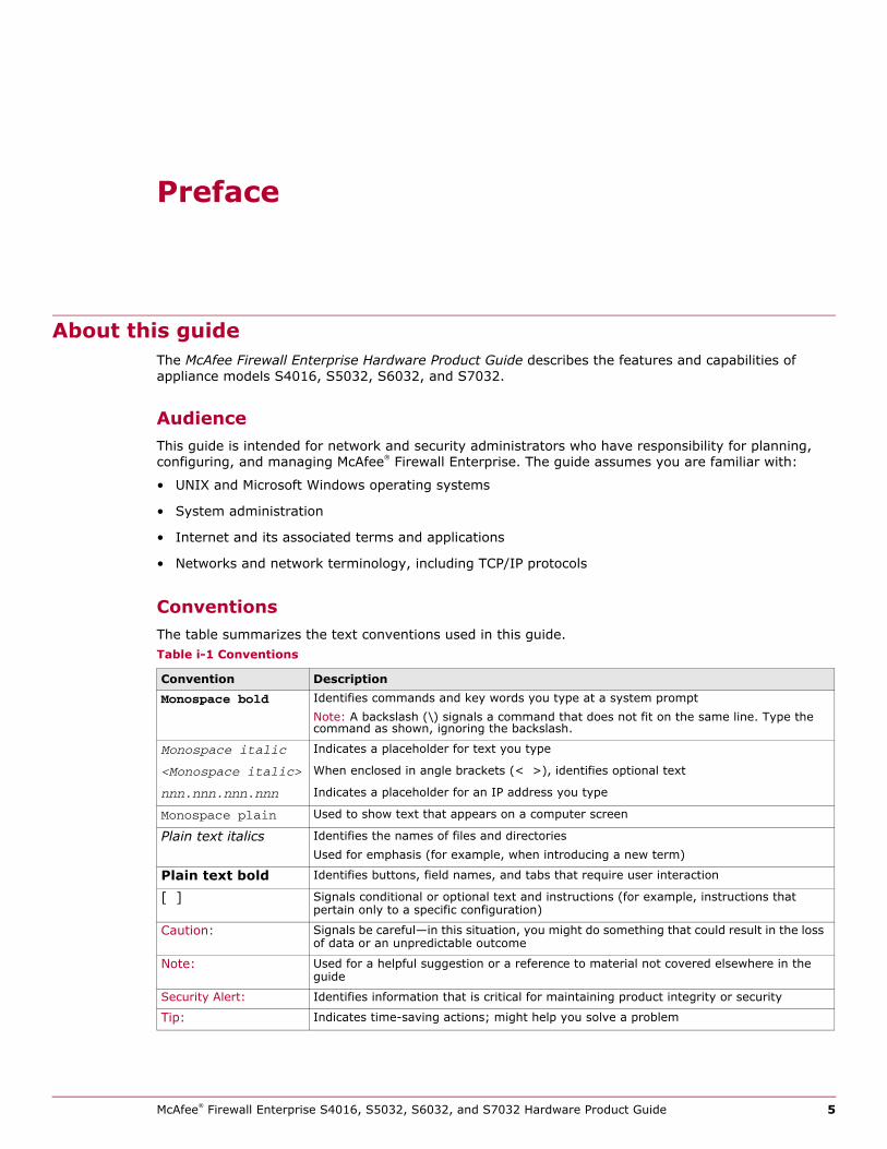
ConventionsThe table summarizes the text conventions used in this guide.Table i-1 Conventions
Convention DescriptionMonospace bold Identifies commands and key words you type at a system prompt
Note: A backslash (\) signals a command that does not fit on the same line. Type the command as shown, ignoring the backslash.
Monospace italic Indicates a placeholder for text you type
<Monospace italic> When enclosed in angle brackets (< >), identifies optional text
nnn.nnn.nnn.nnn Indicates a placeholder for an IP address you type
Monospace plain Used to show text that appears on a computer screen
Plain text italics Identifies the names of files and directoriesUsed for emphasis (for example, when introducing a new term)
Plain text bold Identifies buttons, field names, and tabs that require user interaction
[ ] Signals conditional or optional text and instructions (for example, instructions that pertain only to a specific configuration)
Caution: Signals be careful—in this situation, you might do something that could result in the loss of data or an unpredictable outcome
Note: Used for a helpful suggestion or a reference to material not covered elsewhere in the guide
Security Alert: Identifies information that is critical for maintaining product integrity or security
Tip: Indicates time-saving actions; might help you solve a problem
McAfee® Firewall Enterprise S4016, S5032, S6032, and S7032 Hardware Product Guide 5
Find product information
Note: The IP addresses, screen captures, and graphics used within this document are for illustration purposes only. They are not intended to represent a complete or appropriate configuration for your specific needs. Features might be enabled in screen captures to make them clear; however, not all features are appropriate or desirable for your setup.
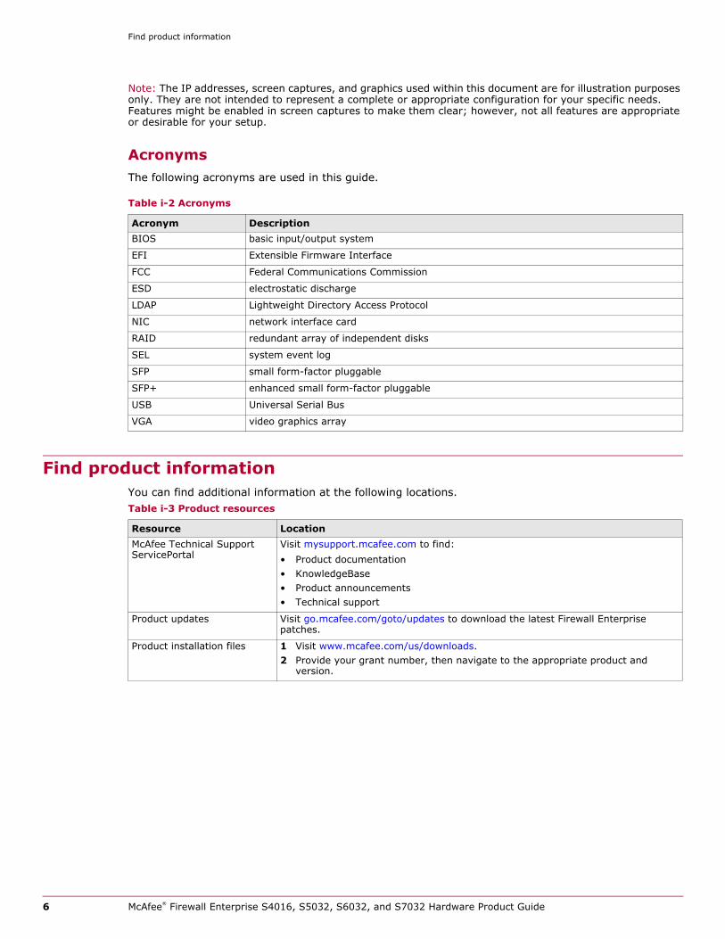
AcronymsThe following acronyms are used in this guide.
Find product informationYou can find additional information at the following locations.
Table i-2 Acronyms
Acronym DescriptionBIOS basic input/output system
EFI Extensible Firmware Interface
FCC Federal Communications Commission
ESD electrostatic discharge
LDAP Lightweight Directory Access Protocol
NIC network interface card
RAID redundant array of independent disks
SEL system event log
SFP small form-factor pluggable
SFP+ enhanced small form-factor pluggable
USB Universal Serial Bus
VGA video graphics array
Table i-3 Product resources
Resource LocationMcAfee Technical Support ServicePortal
Visit mysupport.mcafee.com to find:• Product documentation• KnowledgeBase• Product announcements• Technical support
Product updates Visit go.mcafee.com/goto/updates to download the latest Firewall Enterprise patches.
Product installation files 1 Visit www.mcafee.com/us/downloads.2 Provide your grant number, then navigate to the appropriate product and
version.
6 McAfee® Firewall Enterprise S4016, S5032, S6032, and S7032 Hardware Product Guide
1 Introducing the appliances
ContentsAbout the models on page 7
Software support on page 9
Network ports on page 10
Management ports on page 12
Replaceable hardware components on page 13
Regulatory information on page 14
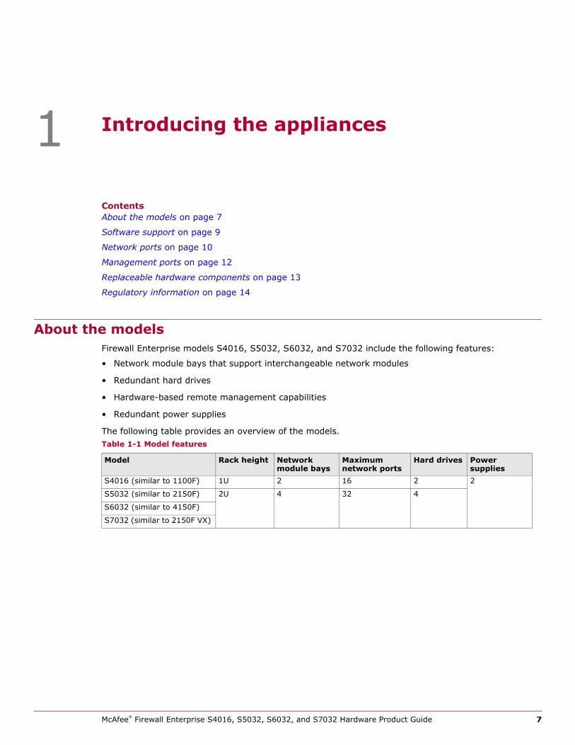
About the modelsFirewall Enterprise models S4016, S5032, S6032, and S7032 include the following features:
• Network module bays that support interchangeable network modules
• Redundant hard drives
• Hardware-based remote management capabilities
• Redundant power supplies
The following table provides an overview of the models.Table 1-1 Model features
Model Rack height Network module bays
Maximum network ports
Hard drives Power supplies
S4016 (similar to 1100F) 1U 2 16 2 2
S5032 (similar to 2150F) 2U 4 32 4
S6032 (similar to 4150F)
S7032 (similar to 2150F VX)
McAfee® Firewall Enterprise S4016, S5032, S6032, and S7032 Hardware Product Guide 7
Introducing the appliancesAbout the models1
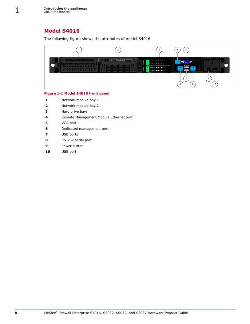
Model S4016The following figure shows the attributes of model S4016.
Figure 1-1 Model S4016 front panel
1 Network module bay 1
2 Network module bay 2
3 Hard drive bays
4 Remote Management Module Ethernet port
5 VGA port
6 Dedicated management port
7 USB ports
8 RS-232 serial port
9 Power button
10 USB port
8 McAfee® Firewall Enterprise S4016, S5032, S6032, and S7032 Hardware Product Guide
Introducing the appliancesSoftware support 1
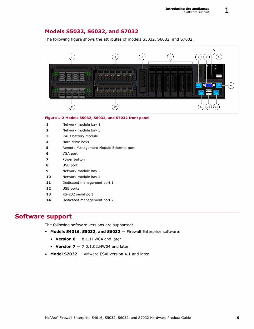
Models S5032, S6032, and S7032The following figure shows the attributes of models S5032, S6032, and S7032.
Figure 1-2 Models S5032, S6032, and S7032 front panel
Software supportThe following software versions are supported:
• Models S4016, S5032, and S6032 — Firewall Enterprise software:
• Version 8 — 8.1.1HW04 and later
• Version 7 — 7.0.1.02.HW04 and later
• Model S7032 — VMware ESXi version 4.1 and later
1 Network module bay 1
2 Network module bay 3
3 RAID battery module
4 Hard drive bays
5 Remote Management Module Ethernet port
6 VGA port
7 Power button
8 USB port
9 Network module bay 2
10 Network module bay 4
11 Dedicated management port 1
12 USB ports
13 RS-232 serial port
14 Dedicated management port 2
McAfee® Firewall Enterprise S4016, S5032, S6032, and S7032 Hardware Product Guide 9
Introducing the appliancesNetwork ports1
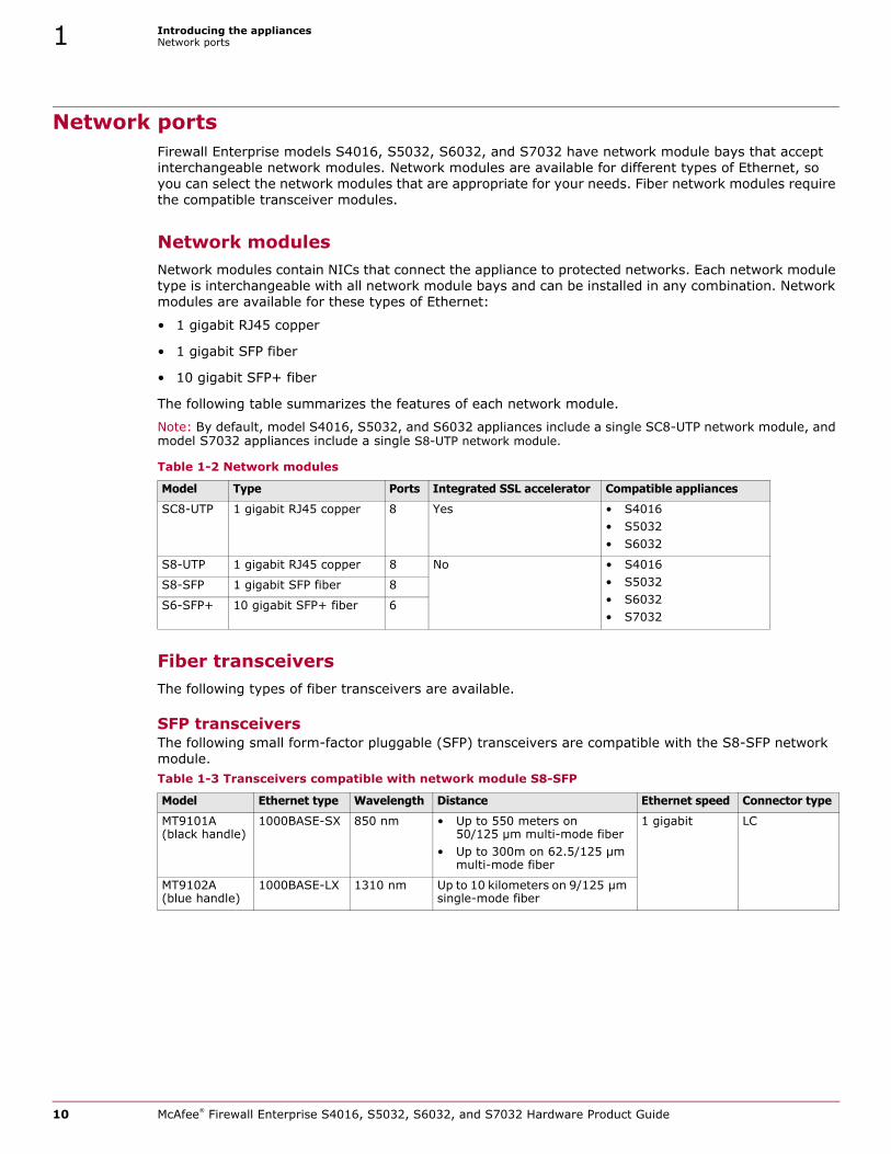
Network portsFirewall Enterprise models S4016, S5032, S6032, and S7032 have network module bays that accept interchangeable network modules. Network modules are available for different types of Ethernet, so you can select the network modules that are appropriate for your needs. Fiber network modules require the compatible transceiver modules.
Network modulesNetwork modules contain NICs that connect the appliance to protected networks. Each network module type is interchangeable with all network module bays and can be installed in any combination. Network modules are available for these types of Ethernet:
• 1 gigabit RJ45 copper
• 1 gigabit SFP fiber
• 10 gigabit SFP+ fiber
The following table summarizes the features of each network module.
Note: By default, model S4016, S5032, and S6032 appliances include a single SC8-UTP network module, and model S7032 appliances include a single S8-UTP network module.
Fiber transceiversThe following types of fiber transceivers are available.
SFP transceiversThe following small form-factor pluggable (SFP) transceivers are compatible with the S8-SFP network module.
Table 1-2 Network modules
Model Type Ports Integrated SSL accelerator Compatible appliances
SC8-UTP 1 gigabit RJ45 copper 8 Yes • S4016• S5032• S6032
S8-UTP 1 gigabit RJ45 copper 8 No • S4016• S5032• S6032• S7032
S8-SFP 1 gigabit SFP fiber 8
S6-SFP+ 10 gigabit SFP+ fiber 6
Table 1-3 Transceivers compatible with network module S8-SFP
Model Ethernet type Wavelength Distance Ethernet speed Connector type
MT9101A (black handle)
1000BASE-SX 850 nm • Up to 550 meters on 50/125 µm multi-mode fiber
• Up to 300m on 62.5/125 µm multi-mode fiber
1 gigabit LC
MT9102A (blue handle)
1000BASE-LX 1310 nm Up to 10 kilometers on 9/125 µm single-mode fiber
10 McAfee® Firewall Enterprise S4016, S5032, S6032, and S7032 Hardware Product Guide
Introducing the appliancesNetwork ports 1
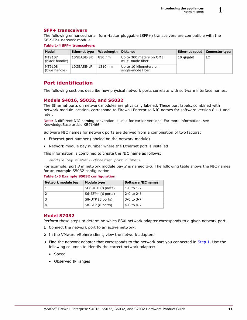
SFP+ transceiversThe following enhanced small form-factor pluggable (SFP+) transceivers are compatible with the S6-SFP+ network module.
Port identificationThe following sections describe how physical network ports correlate with software interface names.
Models S4016, S5032, and S6032The Ethernet ports on network modules are physically labeled. These port labels, combined with network module location, correspond to Firewall Enterprise NIC names for software version 8.1.1 and later.
Note: A different NIC naming convention is used for earlier versions. For more information, see KnowledgeBase article KB71466.
Software NIC names for network ports are derived from a combination of two factors:
• Ethernet port number (labeled on the network module)
• Network module bay number where the Ethernet port is installed
This information is combined to create the NIC name as follows:
<module bay number>-<Ethernet port number>
For example, port 3 in network module bay 2 is named 2-3. The following table shows the NIC names for an example S5032 configuration.
Model S7032Perform these steps to determine which ESXi network adapter corresponds to a given network port.
1 Connect the network port to an active network.
2 In the VMware vSphere client, view the network adapters.
3 Find the network adapter that corresponds to the network port you connected in Step 1. Use the following columns to identify the correct network adapter:
• Speed
• Observed IP ranges
Table 1-4 SFP+ transceivers
Model Ethernet type Wavelength Distance Ethernet speed Connector type
MT9107 (black handle)
10GBASE-SR 850 nm Up to 300 meters on OM3 multi-mode fiber
10 gigabit LC
MT9108 (blue handle)
10GBASE-LR 1310 nm Up to 10 kilometers on single-mode fiber
Table 1-5 Example S5032 configuration
Network module bay Module type Software NIC names
1 SC8-UTP (8 ports) 1-0 to 1-7
2 S6-SFP+ (6 ports) 2-0 to 2-5
3 S8-UTP (8 ports) 3-0 to 3-7
4 S8-SFP (8 ports) 4-0 to 4-7
McAfee® Firewall Enterprise S4016, S5032, S6032, and S7032 Hardware Product Guide 11
Introducing the appliancesManagement ports1
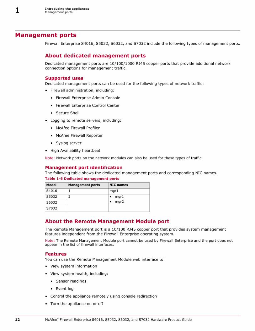
Management portsFirewall Enterprise S4016, S5032, S6032, and S7032 include the following types of management ports.
About dedicated management portsDedicated management ports are 10/100/1000 RJ45 copper ports that provide additional network connection options for management traffic.
Supported usesDedicated management ports can be used for the following types of network traffic:
• Firewall administration, including:
• Firewall Enterprise Admin Console
• Firewall Enterprise Control Center
• Secure Shell
• Logging to remote servers, including:
• McAfee Firewall Profiler
• McAfee Firewall Reporter
• Syslog server
• High Availability heartbeat
Note: Network ports on the network modules can also be used for these types of traffic.
Management port identificationThe following table shows the dedicated management ports and corresponding NIC names.
About the Remote Management Module portThe Remote Management port is a 10/100 RJ45 copper port that provides system management features independent from the Firewall Enterprise operating system.
Note: The Remote Management Module port cannot be used by Firewall Enterprise and the port does not appear in the list of firewall interfaces.
FeaturesYou can use the Remote Management Module web interface to:
• View system information
• View system health, including:
• Sensor readings
• Event log
• Control the appliance remotely using console redirection
• Turn the appliance on or off
Table 1-6 Dedicated management ports
Model Management ports NIC names
S4016 1 mgr1
S5032 2 • mgr1 • mgr2 S6032
S7032
12 McAfee® Firewall Enterprise S4016, S5032, S6032, and S7032 Hardware Product Guide
Introducing the appliancesReplaceable hardware components 1
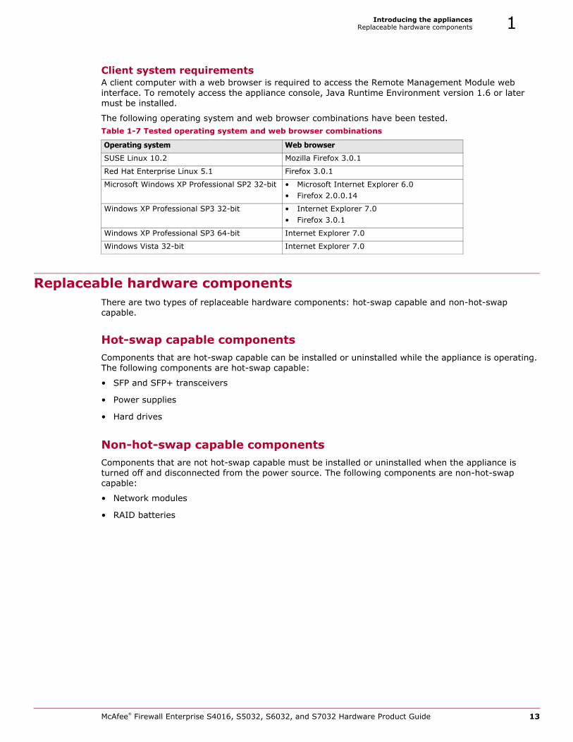
Client system requirementsA client computer with a web browser is required to access the Remote Management Module web interface. To remotely access the appliance console, Java Runtime Environment version 1.6 or later must be installed.
The following operating system and web browser combinations have been tested.
Replaceable hardware componentsThere are two types of replaceable hardware components: hot-swap capable and non-hot-swap capable.
Hot-swap capable componentsComponents that are hot-swap capable can be installed or uninstalled while the appliance is operating. The following components are hot-swap capable:
• SFP and SFP+ transceivers
• Power supplies
• Hard drives
Non-hot-swap capable componentsComponents that are not hot-swap capable must be installed or uninstalled when the appliance is turned off and disconnected from the power source. The following components are non-hot-swap capable:
• Network modules
• RAID batteries
Table 1-7 Tested operating system and web browser combinations
Operating system Web browser
SUSE Linux 10.2 Mozilla Firefox 3.0.1
Red Hat Enterprise Linux 5.1 Firefox 3.0.1
Microsoft Windows XP Professional SP2 32-bit • Microsoft Internet Explorer 6.0• Firefox 2.0.0.14
Windows XP Professional SP3 32-bit • Internet Explorer 7.0• Firefox 3.0.1
Windows XP Professional SP3 64-bit Internet Explorer 7.0
Windows Vista 32-bit Internet Explorer 7.0
McAfee® Firewall Enterprise S4016, S5032, S6032, and S7032 Hardware Product Guide 13
Introducing the appliancesRegulatory information1
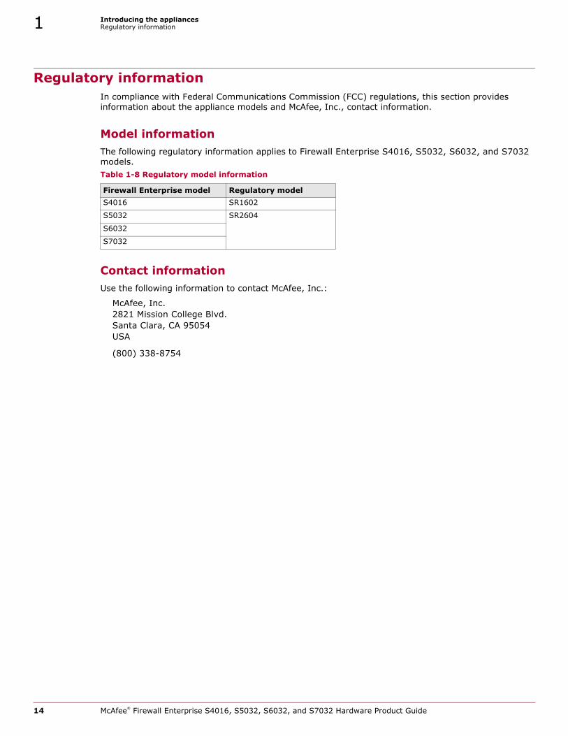
Regulatory informationIn compliance with Federal Communications Commission (FCC) regulations, this section provides information about the appliance models and McAfee, Inc., contact information.
Model informationThe following regulatory information applies to Firewall Enterprise S4016, S5032, S6032, and S7032 models.
Contact informationUse the following information to contact McAfee, Inc.:
McAfee, Inc.2821 Mission College Blvd.Santa Clara, CA 95054USA
(800) 338-8754
Table 1-8 Regulatory model information
Firewall Enterprise model Regulatory modelS4016 SR1602
S5032 SR2604
S6032
S7032
14 McAfee® Firewall Enterprise S4016, S5032, S6032, and S7032 Hardware Product Guide
2 Installing hardware components
ContentsVerify compatibility on page 15
Install or replace a network module on page 16
Install or remove fiber transceivers on page 17
Replace a hard drive on page 18
Replace a power supply on page 19
Replace a RAID battery on page 20
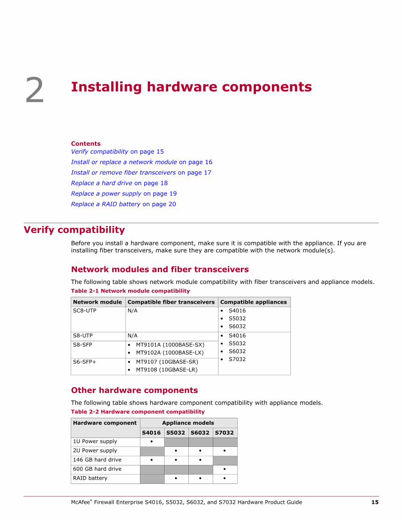
Verify compatibilityBefore you install a hardware component, make sure it is compatible with the appliance. If you are installing fiber transceivers, make sure they are compatible with the network module(s).
Network modules and fiber transceiversThe following table shows network module compatibility with fiber transceivers and appliance models.
Other hardware componentsThe following table shows hardware component compatibility with appliance models.
Table 2-1 Network module compatibility
Network module Compatible fiber transceivers Compatible appliancesSC8-UTP N/A • S4016
• S5032• S6032
S8-UTP N/A • S4016• S5032• S6032• S7032
S8-SFP • MT9101A (1000BASE-SX)• MT9102A (1000BASE-LX)
S6-SFP+ • MT9107 (10GBASE-SR)• MT9108 (10GBASE-LR)
Table 2-2 Hardware component compatibility
Hardware component Appliance models
S4016 S5032 S6032 S70321U Power supply •
2U Power supply • • •
146 GB hard drive • • •
600 GB hard drive •
RAID battery • • •
McAfee® Firewall Enterprise S4016, S5032, S6032, and S7032 Hardware Product Guide 15
Installing hardware componentsInstall or replace a network module2
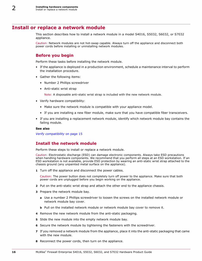
Install or replace a network moduleThis section describes how to install a network module in a model S4016, S5032, S6032, or S7032 appliance.
Caution: Network modules are not hot-swap capable. Always turn off the appliance and disconnect both power cords before installing or uninstalling network modules.
Before you beginPerform these tasks before installing the network module.
• If the appliance is deployed in a production environment, schedule a maintenance interval to perform the installation procedure.
• Gather the following items:
• Number 2 Phillips screwdriver
• Anti-static wrist strap
Note: A disposable anti-static wrist strap is included with the new network module.
• Verify hardware compatibility:
• Make sure the network module is compatible with your appliance model.
• If you are installing a new fiber module, make sure that you have compatible fiber transceivers.
• If you are installing a replacement network module, identify which network module bay contains the failing module.
See also
Verify compatibility on page 15
Install the network modulePerform these steps to install or replace a network module.
Caution: Electrostatic discharge (ESD) can damage electronic components. Always take ESD precautions when handling hardware components. We recommend that you perform all steps at an ESD workstation. If an ESD workstation is not available, provide ESD protection by wearing an anti-static wrist strap attached to the chassis ground (any unpainted metal surface on the appliance).
1 Turn off the appliance and disconnect the power cables.
Caution: The power button does not completely turn off power to the appliance. Make sure that both power cords are unplugged before you begin working on the appliance.
2 Put on the anti-static wrist strap and attach the other end to the appliance chassis.
3 Prepare the network module bay.
a Use a number 2 Phillips screwdriver to loosen the screws on the installed network module or network module bay cover.
b Pull on the installed network module or network module bay cover to remove it.
4 Remove the new network module from the anti-static packaging.
5 Slide the new module into the empty network module bay.
6 Secure the network module by tightening the fasteners with the screwdriver.
7 If you removed a network module from the appliance, place it into the anti-static packaging that came with the new module.
8 Reconnect the power cords, then turn on the appliance.
16 McAfee® Firewall Enterprise S4016, S5032, S6032, and S7032 Hardware Product Guide
Installing hardware componentsInstall or remove fiber transceivers 2
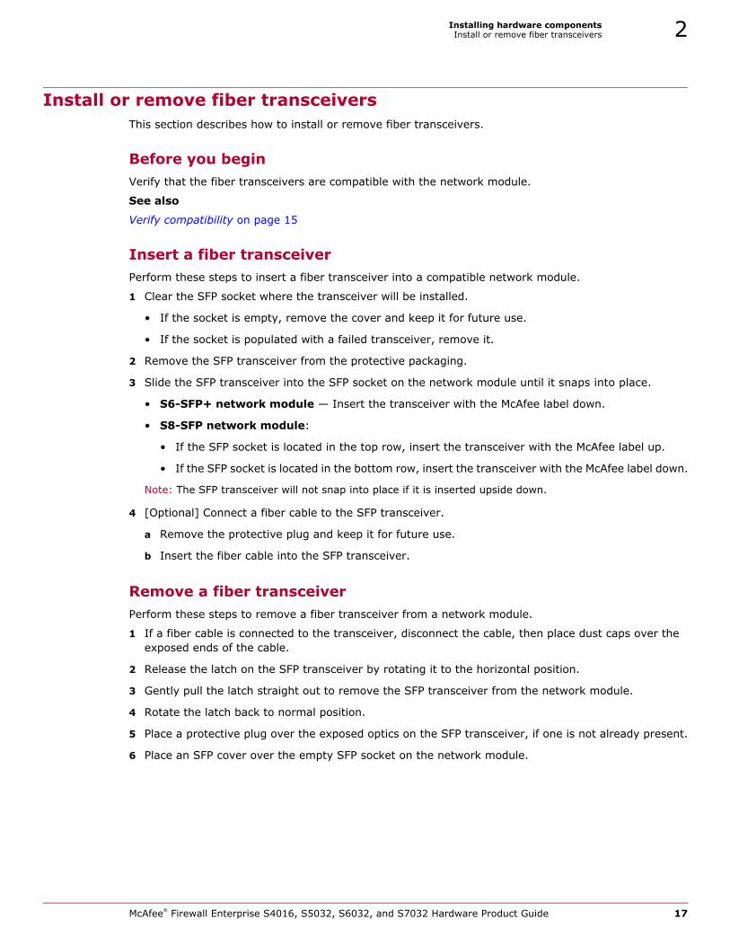
Install or remove fiber transceiversThis section describes how to install or remove fiber transceivers.
Before you beginVerify that the fiber transceivers are compatible with the network module.
See also
Verify compatibility on page 15
Insert a fiber transceiverPerform these steps to insert a fiber transceiver into a compatible network module.
1 Clear the SFP socket where the transceiver will be installed.
• If the socket is empty, remove the cover and keep it for future use.
• If the socket is populated with a failed transceiver, remove it.
2 Remove the SFP transceiver from the protective packaging.
3 Slide the SFP transceiver into the SFP socket on the network module until it snaps into place.
• S6-SFP+ network module — Insert the transceiver with the McAfee label down.
• S8-SFP network module:
• If the SFP socket is located in the top row, insert the transceiver with the McAfee label up.
• If the SFP socket is located in the bottom row, insert the transceiver with the McAfee label down.
Note: The SFP transceiver will not snap into place if it is inserted upside down.
4 [Optional] Connect a fiber cable to the SFP transceiver.
a Remove the protective plug and keep it for future use.
b Insert the fiber cable into the SFP transceiver.
Remove a fiber transceiverPerform these steps to remove a fiber transceiver from a network module.
1 If a fiber cable is connected to the transceiver, disconnect the cable, then place dust caps over the exposed ends of the cable.
2 Release the latch on the SFP transceiver by rotating it to the horizontal position.
3 Gently pull the latch straight out to remove the SFP transceiver from the network module.
4 Rotate the latch back to normal position.
5 Place a protective plug over the exposed optics on the SFP transceiver, if one is not already present.
6 Place an SFP cover over the empty SFP socket on the network module.
McAfee® Firewall Enterprise S4016, S5032, S6032, and S7032 Hardware Product Guide 17
Installing hardware componentsReplace a hard drive2
Replace a hard driveThis section describes how to replace a hard drive in a model S4016, S5032, S6032, or S7032 appliance. Each model uses hot-swap hard drives connected to a RAID controller. The RAID controller allows the system to continue operating in the event that a single disk drive fails. A single failed hard drive can be replaced while the system is still operational.
Before you beginTo replace a hard drive, make sure these prerequisites are met:
• The appliance must have no more than one failed hard drive.
Note: If two or more hard drives have failed, contact technical support for assistance with re-creating the RAID array and restoring the firewall image.
• The replacement hard drive must be the same size or larger than the failed drive.
See also
Verify compatibility on page 15
Replace the drivePerform these steps to remove a failed hard drive and replace it with a new one.
1 Identify the failed hard drive.
Tip: A failed hard drive typically has an amber indicator light.
2 Remove the failed hard drive from the appliance.
a Press the aqua latch on the failed hard drive to release the spring-loaded black handle.
b Remove the failed hard drive from the appliance by pulling on the black handle.
3 Prepare the replacement hard drive.
a Remove the replacement hard drive from the protective packaging.
b Compare the replacement hard drive to the failed hard drive to make sure the replacement hard drive has similar or greater capacity.
Note: A smaller hard drive will not work. Contact technical support if you received a replacement hard drive that is smaller than the failed hard drive.
c Press the aqua latch to release the spring-loaded black handle.
4 Insert the replacement hard drive into the appliance.
a Slide the drive into the empty hard drive bay until it is fully seated.
b Press the black handle until it latches.
c If the appliance is turned off, turn it on.
After the drive is inserted, the RAID controller begins the rebuild operation. When the rebuild operation begins, each hard drive shows activity. You can monitor the rebuild process:
• Models S4016, S5032, and S6032 — RAID messages appear on the system console.
• Model S7032 — The VMware vSphere Client shows RAID status.
Caution: Do not turn off the appliance until the rebuild operation is complete.
Note: Performance is reduced while the rebuild operation takes place.
5 Place the failed hard drive in the packaging materials from the replacement hard drive.
18 McAfee® Firewall Enterprise S4016, S5032, S6032, and S7032 Hardware Product Guide

Installing hardware componentsReplace a power supply 2
Replace a power supplyThis section describes how to replace a power supply in a model S4016, S5032, S6032, or S7032 appliance. Each model has dual supplies that allow the appliance to continue operating if one power supply fails. The power supplies are hot swappable, so a single power supply can be replaced while the system is still operating.
A power supply can be replaced while the appliance is turned on and running or when the appliance turned off.
Note: Use both power supplies in normal operation so that two power supplies share the load.
Before you beginPerform these tasks before installing the power supply.
• Verify that the replacement power supply is compatible with your appliance model.
• Identify the failed power supply.
See also
Verify compatibility on page 15
Replace the power supplyPerform these steps to replace a power supply.
1 Disconnect the power cord from the failed power supply.
2 Remove the failed power supply.
a Unlatch the failed power supply.
• Model S4016 — Press the aqua handle down.
• Model S5032, S6032, and S7032 — Press the aqua handle sideways towards the black handle.
b Continue pressing the aqua handle and remove the power supply by pulling the black handle.
3 Remove the replacement power supply from the protective packaging.
4 Slide the replacement power supply into the appliance until it is fully seated and the latch has engaged.
5 Connect the power cord to the replacement power supply.
McAfee® Firewall Enterprise S4016, S5032, S6032, and S7032 Hardware Product Guide 19
Installing hardware componentsReplace a RAID battery2
Replace a RAID batteryThis section describes how to replace a RAID battery in a model S5032, S6032, or S7032 appliance. The battery provides power to the cache memory of the RAID controller in the event of sudden power loss.
Caution: RAID batteries are not hot-swap capable. Always turn off the appliance and disconnect both power cords before installing or uninstalling a RAID battery. Never operate the appliance without the RAID battery installed.
Before you beginPerform these tasks before replacing a RAID battery.
• If the appliance is deployed in a production environment, schedule a maintenance interval to perform the replacement procedure.
• Gather the following items:
• Number 2 Phillips screwdriver
• Anti-static wrist strap
Note: A disposable anti-static wrist strap is included with the new RAID battery.
Install the RAID batteryPerform these steps to replace a RAID battery.
Caution: Electrostatic discharge (ESD) can damage electronic components. Always take ESD precautions when handling hardware components. We recommend that you perform all steps at an ESD workstation. If an ESD workstation is not available, provide ESD protection by wearing an anti-static wrist strap attached to the chassis ground (any unpainted metal surface on the appliance).
1 Turn off the appliance and disconnect the power cables.
Caution: The power button does not completely turn off power to the appliance. Make sure that both power cords are unplugged before you begin working on the appliance.
2 Put on the anti-static wrist strap and attach the other end to the appliance chassis.
3 Remove the old battery tray from the appliance.
a Find the battery tray, which is located between the network module bays and the hard drive bays.
b Use a number 2 Phillips screwdriver to loosen the screws on the battery tray.
c Pull the battery tray out of the appliance.
Note: The battery is connected to the appliance by a cable, which is long enough to allow you to remove the tray from the appliance.
d Gently unplug the cable from the battery.
4 Install the replacement battery.
a Unpack the replacement battery tray.
b Gently plug the cable into the new battery.
c Slide the new battery tray into the appliance.
d Use a number 2 Phillips screwdriver to tighten the screws on the battery tray.
5 Reconnect the power cords, then turn on the appliance.
6 Place the old battery in the packaging materials from the replacement battery.
20 McAfee® Firewall Enterprise S4016, S5032, S6032, and S7032 Hardware Product Guide
3 Configuring the management ports
ContentsConfigure a dedicated management port on page 21
Configure the Remote Management Module on page 22
Configure a dedicated management portThe dedicated management ports are disabled by default. To configure and enable a dedicated management port, perform these steps.
1 Create a zone for the management network.
2 Configure the NIC that corresponds to the dedicated management port and assign it to the management zone.
3 Create or modify access control rules to allow the appropriate management traffic.
See also
About dedicated management ports on page 12
McAfee® Firewall Enterprise S4016, S5032, S6032, and S7032 Hardware Product Guide 21
Configuring the management portsConfigure the Remote Management Module3
Configure the Remote Management ModuleThe Remote Management Module is disabled by default. Perform these tasks to configure and use the Remote Management Module port.
See also
About the Remote Management Module port on page 12
Before you beginIf the appliance is deployed in a production environment, schedule a maintenance interval to enable the Remote Management Module.
Connect the Remote Management Module port To use the Remote Management Module, connect the Remote Management Module port to a network.
Caution: McAfee recommends connecting the Remote Management Module port to a dedicated management network that meets the security needs of your organization.
Enable the Remote Management ModulePerform these steps to configure and enable the Remote Management Module.
1 Enter the appliance BIOS menu.
a Restart or turn on the appliance.
b Press F2 to enter the BIOS menu.
c Navigate to the Server Management tab.
d Select BMC LAN Configuration.
2 Configure the following options:
• IP address
• Subnet mask
• Gateway IP address
3 In the User configuration area, specify at least one user that will be allowed to access the appliance from a remote host.
a In the User ID field, select the user ID that you want to configure.
Tip: The appliance has five user IDs for user information: anonymous, root, User3, User4, and User5. Each user ID can be enabled or disabled and assigned a privilege.
b Configure the following options:
• Privilege
• User name
• User password
c In the User status field, select Enable to activate the user ID.
4 Press F10 to exit the BIOS and save the changes.
22 McAfee® Firewall Enterprise S4016, S5032, S6032, and S7032 Hardware Product Guide
Configuring the management portsConfigure the Remote Management Module 3
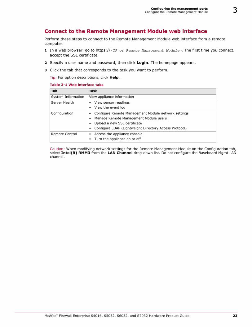
Connect to the Remote Management Module web interfacePerform these steps to connect to the Remote Management Module web interface from a remote computer.
1 In a web browser, go to https://<IP of Remote Management Module>. The first time you connect, accept the SSL certificate.
2 Specify a user name and password, then click Login. The homepage appears.
3 Click the tab that corresponds to the task you want to perform.
Tip: For option descriptions, click Help.
Caution: When modifying network settings for the Remote Management Module on the Configuration tab, select Intel(R) RMM3 from the LAN Channel drop-down list. Do not configure the Baseboard Mgmt LAN channel.
Table 3-1 Web interface tabs
Tab Task
System Information View appliance information
Server Health • View sensor readings• View the event log
Configuration • Configure Remote Management Module network settings • Manage Remote Management Module users• Upload a new SSL certificate• Configure LDAP (Lightweight Directory Access Protocol)
Remote Control • Access the appliance console • Turn the appliance on or off
McAfee® Firewall Enterprise S4016, S5032, S6032, and S7032 Hardware Product Guide 23

Configuring the management portsConfigure the Remote Management Module3
24 McAfee® Firewall Enterprise S4016, S5032, S6032, and S7032 Hardware Product Guide
4 Re-imaging an appliance
ContentsAbout re-imaging on page 25
Re-image the appliance on page 25
About re-imagingFirewall Enterprise models S4016, S5032, S6032, and S7032 include an integrated device that allows the appliances to be re-imaged without external media. The integrated device includes two software versions:
• Current version that was pre-installed on the appliance
• Previous version
Caution: Re-imaging an appliance removes all configuration and log data.
Re-image the applianceIf you need to re-image your appliance, use the integrated installation media to install a fresh image.
Before you beginIf the appliance is deployed in a production environment, schedule a maintenance interval to re-image.
Re-image a model S4016, S5032, and S6032 appliancePerform these steps to re-image your appliance.
1 Connect your appliance to a monitor and keyboard or serial console.
2 Restart or turn on the appliance.
3 When the appliance starts, press F6 to access the one-time boot settings.
4 From the list of boot options, select McAfee Firewall.
The appliance boots from the integrated installation media and displays standard boot-up information.
5 At the “Welcome to Firewall Enterprise!” menu, select the appropriate option.
• If you are using a mouse and keyboard, type 1, then press Enter.
• If you intend to use a serial console, type 4, then press Enter.
The appliance continues starting, then a confirmation message appears.
6 To continue, press Y.
McAfee® Firewall Enterprise S4016, S5032, S6032, and S7032 Hardware Product Guide 25
Re-imaging an applianceRe-image the appliance4
7 Choose which Firewall Enterprise version to install.
a Select Version Selection, then press Enter.
b Use the arrow keys and the spacebar to select the version you want to install.
c Select OK, then press Enter.
8 Install Firewall Enterprise.
a Select Express Install, then press Enter.
Installation begins. When the operation is complete, the menu appears.
b Select Exit Install, then press Enter.
c At the confirmation prompt, select Yes, then press Enter.
The appliance restarts and boots the Firewall Enterprise version you installed.
9 Provide the initial configuration using one of these methods:
• Insert a USB drive containing a disaster recovery backup into one of the appliance USB ports.
• Use the Quick Start Wizard on a Windows-based computer to create an initial configuration file and save it to a USB drive, then insert the USB drive into the appliance.
• Complete the text-based Quick Start Wizard at the appliance terminal.
Re-image a model S7032 applianceFor re-imaging instructions, see the McAfee Firewall Enterprise, Multi-Firewall Edition Installation Guide, model S7032.
26 McAfee® Firewall Enterprise S4016, S5032, S6032, and S7032 Hardware Product Guide
5 Diagnosing hardware problems
ContentsRun hardware diagnostics on page 27
View the system event log on page 29
Run hardware diagnosticsFirewall Enterprise models S4016, S5032, S6032, and S7032 include an integrated hardware diagnostics tool you can use to diagnose hardware problems. The diagnostics utility is independent of the appliance operating system, so the appliance must be restarted to run the diagnostics.
Before you beginPrepare your appliance to run the diagnostics.
• If the appliance is deployed in a production environment, schedule a maintenance interval to run hardware diagnostics.
• Make sure your appliance is not connected to a network.
Note: If you want to run a comprehensive test on the NIC ports, use a crossover cable to connect any network port to another port in the same system.
Run hardware diagnosticsPerform these steps to run hardware diagnostics on your appliance.
1 Connect your appliance to a monitor and keyboard.
2 Start the diagnostic utility.
a Restart or turn on the appliance.
b When the appliance starts, press F6 to access the one-time boot settings.
c From the list of boot options, select Internal EFI Shell.
The EFI shell starts and a countdown timer appears. When the countdown is complete, the Intel Diagnostic Tool menu appears.
Caution: Wait for the countdown to finish. Do not press any key.
d At the fs0:\> prompt, run the pct command.
e Press any key (except Q) to accept the license agreement. The Platform Confidence Test Options page appears.
McAfee® Firewall Enterprise S4016, S5032, S6032, and S7032 Hardware Product Guide 27
Diagnosing hardware problemsRun hardware diagnostics5
3 Run the hardware test.
a Select the test to run, then press Enter.
Tip: Select Display Help Text for test descriptions.
b When the hardware evaluation ends, press Enter. The hardware test begins. When the test is complete, the Test Result Summary page appears.
c Review the test results. When you are finished, press Enter. The Platform Confidence Test Options page appears.
4 Run an additional test or finish testing.
• To run another test, select the test to run, then press Enter.
Note: If you ran a comprehensive test, perform a full AC power recycle before retesting the appliance.
• To finish testing, select Exit and press Enter, then press a key to continue.
5 [Optional] To view the log file created by the diagnostics, run the following command.
edit fsz:\result.log
6 To restart the appliance, run the reset command.
28 McAfee® Firewall Enterprise S4016, S5032, S6032, and S7032 Hardware Product Guide
Diagnosing hardware problemsView the system event log 5
View the system event logYou can view the system event log (SEL) by connecting to the Remote Management Module or by using the integrated system event log viewer.
Note: If the Firewall Enterprise IPMI daemon (ipmid) is enabled, system event log events are converted to firewall audit entries and removed from the system event log. If you want to use the system event log to monitor hardware events instead of the firewall audit, disable ipmid by running the command cf daemond disable agent=ipmid.
Use the Remote Management Module to view the system event logPerform these steps to use the Remote Management Module to view the system event log.
1 In a web browser, go to https://<IP of Remote Management Module>.
2 Specify your credentials and log on.
3 Click the Server Health tab.
4 Click Event Log.
Use the integrated system event log viewerPerform these steps to use the integrated system event log viewer to view the system event log.
1 Connect your appliance to a monitor and keyboard.
2 Restart or turn on the appliance.
3 When the appliance starts, press F6 to access the one-time boot settings.
4 From the list of boot options, select Internal EFI Shell.
The EFI shell starts and a countdown timer appears. When the countdown is complete, the Intel Diagnostic Tool menu appears.
Caution: Wait for the countdown to finish. Do not press any key.
5 At the fs0:\> prompt, run the sel command. The system event log viewer appears.
Tip: For instructions on how to use the system event log viewer, select Help.
McAfee® Firewall Enterprise S4016, S5032, S6032, and S7032 Hardware Product Guide 29

Diagnosing hardware problemsView the system event log5
30 McAfee® Firewall Enterprise S4016, S5032, S6032, and S7032 Hardware Product Guide


700-3019A00