Embed Size (px)
Citation preview

8/3/2019 Hardware Slides 12
http://slidepdf.com/reader/full/hardware-slides-12 1/29
DOC 112: Computer Hardware Lecture 12 Slide 1
Lecture 12:
Registers, Multiplexers, Decoders,Comparators and What Nots

8/3/2019 Hardware Slides 12
http://slidepdf.com/reader/full/hardware-slides-12 2/29
DOC 112: Computer Hardware Lecture 12 Slide 2
After Karnaugh maps - what next?
Since we already know how to design both combinational
and sequential circuits, what else is there to learn about
digital circuits?
Actually, most practical digital circuit design problems are
too large to be solved by minimisation and Karnaugh
maps. They have to be solved by:
DIGITAL BUILDING BLOCKS
using
FUNCTIONAL DESIGN

8/3/2019 Hardware Slides 12
http://slidepdf.com/reader/full/hardware-slides-12 3/29
DOC 112: Computer Hardware Lecture 12 Slide 3
Registers
The most fundamental digital building block of a digital
computer is the register, which is an ordered group of single bit
flip-flops with one clock signal connected to all of them.

8/3/2019 Hardware Slides 12
http://slidepdf.com/reader/full/hardware-slides-12 4/29
DOC 112: Computer Hardware Lecture 12 Slide 4
Registers (continued)
By convention we number the bits from 0 to N-1 for a N-bit
register and may assign its content the positive numerical
value (2^n)*OB(n).
(However, it is important to remember that bits can be
interpreted in any way you wish).We also have short hand notations for registers. Three of the
most common are:
Registers can contain either data or control bits.

8/3/2019 Hardware Slides 12
http://slidepdf.com/reader/full/hardware-slides-12 5/29DOC 112: Computer Hardware Lecture 12 Slide 5
Register Transfer Operations
Simple Register Transfer:
the contents of one register (source) is copied into another
(destination) without affecting the contents of the first.
NB 1 wire/switchfor each bit in thesource register

8/3/2019 Hardware Slides 12
http://slidepdf.com/reader/full/hardware-slides-12 6/29DOC 112: Computer Hardware Lecture 12 Slide 6
Operation of the Register Transfer Circuit
R destination R source
Select the Input register (Source)
Select the Output Register (Destination)
Transfer data from the Source Register to the
Destination Register

8/3/2019 Hardware Slides 12
http://slidepdf.com/reader/full/hardware-slides-12 7/29DOC 112: Computer Hardware Lecture 12 Slide 7
Select the Source Register
The source register may be selected by a Multiplexer
circuit. (One multiplexer per bit)
A 4-to-1 Multiplexer:
0
11
1
1
X
00
1
1
X
01
0
1
0
AB
C
D
ENBL SEL0 SEL1 OUT

8/3/2019 Hardware Slides 12
http://slidepdf.com/reader/full/hardware-slides-12 8/29
DOC 112: Computer Hardware Lecture 12 Slide 8
8-to-1 Multiplexer
Since we have 8registers we need an
8-1 multiplexer.
We could design this at
the gate level, but
functional design is
much simpler

8/3/2019 Hardware Slides 12
http://slidepdf.com/reader/full/hardware-slides-12 9/29
DOC 112: Computer Hardware Lecture 12 Slide 9
Register Transfer using an 8-1 Multiplexer
We can now wire up each bit
of the register transfer
circuit.
The circuit for bit i is shown.

8/3/2019 Hardware Slides 12
http://slidepdf.com/reader/full/hardware-slides-12 10/29
DOC 112: Computer Hardware Lecture 12 Slide 10
Another Possible Use of the Multiplexer
If you could use a 4-to-1 multiplexer, your assessed course
work would be trivial!
Say, you needed AeorB for C1C2=00, B for C1C2=01, A'•B
for C1C2=10, A'+B for C1C2=01.
Note that: AeorB = AB'+A'B and A'+B = (AB')'

8/3/2019 Hardware Slides 12
http://slidepdf.com/reader/full/hardware-slides-12 11/29
DOC 112: Computer Hardware Lecture 12 Slide 11
Another Possible Use of the Multiplexer
If you could use a 4-to-1 multiplexer, your assessed course
work would be trivial!
Say, you needed AeorB for C1C2=00, B for C1C2=01, A'•B
for C1C2=10, A'+B for C1C2=01.
Note that: AeorB = AB'+A'B and A'+B = (AB')'

8/3/2019 Hardware Slides 12
http://slidepdf.com/reader/full/hardware-slides-12 12/29
DOC 112: Computer Hardware Lecture 12 Slide 12
Another Possible Use of the Multiplexer
This saves not only design time but £s as well!
If you could use a 4-to-1 multiplexer, your assessed course
work would be trivial!
Say, you needed AeorB for C1C2=00, B for C1C2=01, A'•B
for C1C2=10, A'+B for C1C2=01.
Note that: AeorB = AB'+A'B and A'+B = (AB')'

8/3/2019 Hardware Slides 12
http://slidepdf.com/reader/full/hardware-slides-12 13/29
DOC 112: Computer Hardware Lecture 12 Slide 13
Output Control for The Register Transfer Circuit
So far, by using a multiplexer, we have been able to select the source
register whose contents are fed back to the inputs of all the registers.
In order to complete the transfer, a clock pulse must be applied to the
destination register. No clock pulse should be applied to any other register.
A Demultiplexer can be used to switch a clock pulse on one out of eigh
lines. This device has three selection inputs, one enable input and
eight outputs.
8/3/2019 Hardware Slides 12
http://slidepdf.com/reader/full/hardware-slides-12 14/29
DOC 112: Computer Hardware Lecture 12 Slide 14
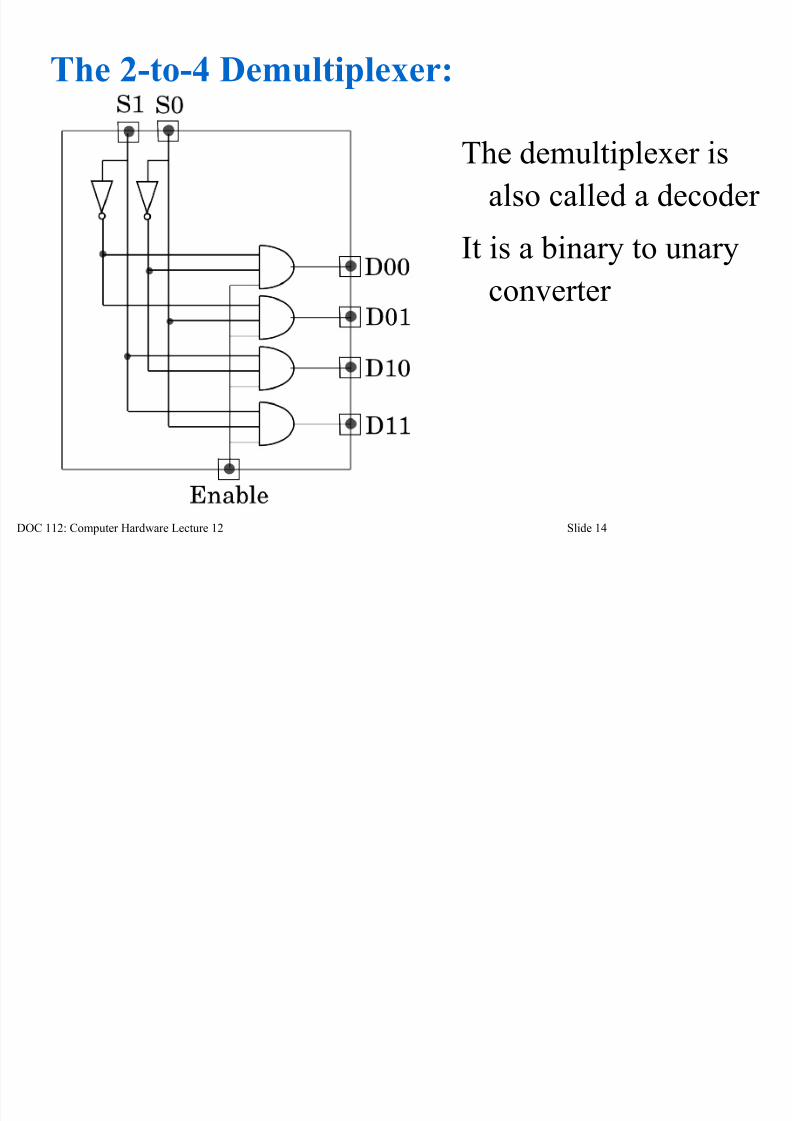
The 2-to-4 Demultiplexer:
The demultiplexer is
also called a decoder
It is a binary to unary
converter

8/3/2019 Hardware Slides 12
http://slidepdf.com/reader/full/hardware-slides-12 15/29
DOC 112: Computer Hardware Lecture 12 Slide 15
Operation of the 2-to-4 Demultiplexer
A good way to describe the operation of a decoder or
demultiplexer is to look at its functional truth table:
The selection of the output is therefore determined
by the values on the selection lines.
When the enable input is: 0 all outputs are 0.
1 one of the outputs is 1.
0
1
1
1
1
X X
0 00 1
1 0
1 1
0 0 0 0
1 0 0 00 1 0 0
0 0 1 0
0 0 0 1
ENBL SEL1 SEL2 D00 D01 D10 D11

8/3/2019 Hardware Slides 12
http://slidepdf.com/reader/full/hardware-slides-12 16/29
DOC 112: Computer Hardware Lecture 12 Slide 16
Expansion to a 3-to-8 Demultiplexer
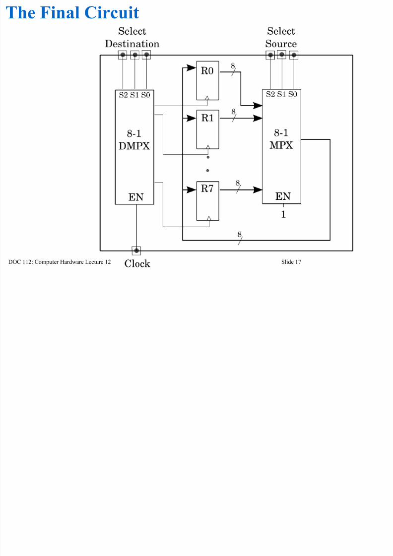
The Final Circuit
8/3/2019 Hardware Slides 12
http://slidepdf.com/reader/full/hardware-slides-12 17/29
DOC 112: Computer Hardware Lecture 12 Slide 17
The Final Circuit
d k i 30 d

8/3/2019 Hardware Slides 12
http://slidepdf.com/reader/full/hardware-slides-12 18/29
DOC 112: Computer Hardware Lecture 12 Slide 18
How to do your coursework in 30 seconds
0 0 0 0 0
0 0 0 1 10 0 1 0 10 0 1 1 00 1 0 0 00 1 0 1 10 1 1 0 0
0 1 1 1 11 0 0 0 01 0 0 1 11 0 1 0 01 0 1 1 01 1 0 0 1
1 1 0 1 11 1 1 0 01 1 1 1 1
C1 C2 A B Out
A B
B
A' · B
A' + B
Decoders are very powerful functionaldevices!
H d k i 30 d

8/3/2019 Hardware Slides 12
http://slidepdf.com/reader/full/hardware-slides-12 19/29
DOC 112: Computer Hardware Lecture 12 Slide 19
How to do your coursework in 30 seconds
D0000
D1111
S3 S2 S1 S0
4-to-16
demultiplexer
C1 C2 A B
0 0 0 0 0
0 0 0 1 10 0 1 0 10 0 1 1 00 1 0 0 00 1 0 1 10 1 1 0 0
0 1 1 1 11 0 0 0 01 0 0 1 11 0 1 0 01 0 1 1 01 1 0 0 1
1 1 0 1 11 1 1 0 01 1 1 1 1
C1 C2 A B Out
A B
B
A' · B
A' + B
H t d k i 30 d

8/3/2019 Hardware Slides 12
http://slidepdf.com/reader/full/hardware-slides-12 20/29
DOC 112: Computer Hardware Lecture 12 Slide 20
How to do your coursework in 30 seconds
The decoder is a minterm generator!
D0000
D1111
S3 S2 S1 S0
4-to-16
demultiplexer
C1 C2 A B
0 0 0 0 0
0 0 0 1 10 0 1 0 10 0 1 1 00 1 0 0 00 1 0 1 10 1 1 0 0
0 1 1 1 11 0 0 0 01 0 0 1 11 0 1 0 01 0 1 1 01 1 0 0 1
1 1 0 1 11 1 1 0 01 1 1 1 1
C1 C2 A B Out
A B
B
A' · B
A' + B

8/3/2019 Hardware Slides 12
http://slidepdf.com/reader/full/hardware-slides-12 21/29
DOC 112: Computer Hardware Lecture 12 Slide 21
Comparators (computer intelligence?)
Let's build a comparator circuitfor two 4-bit positive binarynumbers.
Nine inputs, three outputs(three 512 entries truth tables?)

8/3/2019 Hardware Slides 12
http://slidepdf.com/reader/full/hardware-slides-12 22/29
DOC 112: Computer Hardware Lecture 12 Slide 22
Comparators (computer intelligence?)
Let's build a comparator circuitfor two 4-bit positive binarynumbers.
Nine inputs, three outputs(three 512 entries truth tables?)
A>B = A3B3' + (A3B3+A3'B3')(A2B2' +
(A2B2+A2'B2')( A1B1' +(A1B1+A1'B1')A0B0') )

8/3/2019 Hardware Slides 12
http://slidepdf.com/reader/full/hardware-slides-12 23/29
DOC 112: Computer Hardware Lecture 12 Slide 23
Comparators (computer intelligence?)
Let's build a comparator circuitfor two 4-bit positive binarynumbers.
Nine inputs, three outputs(three 512 entries truth tables?)
YUK!
A>B = A3B3' + (A3B3+A3'B3')(A2B2' +
(A2B2+A2'B2')( A1B1' +(A1B1+A1'B1')A0B0') )

8/3/2019 Hardware Slides 12
http://slidepdf.com/reader/full/hardware-slides-12 24/29
DOC 112: Computer Hardware Lecture 12 Slide 24
Designing Comparators Functionally
1.Build a one-bit comparator
A>B : AB'
A<B : A'B
A=B : A'B' + AB
B 0 1
A
0 A=B A<B
1 A>B A=B
i i i ll

8/3/2019 Hardware Slides 12
http://slidepdf.com/reader/full/hardware-slides-12 25/29
DOC 112: Computer Hardware Lecture 12 Slide 25
Designing Comparators Functionally
1.Build a one-bit comparator
A>B : AB'
A<B : A'B
A=B : A'B' + AB
B 0 1
A
0 A=B A<B
1 A>B A=B
OR What?
D i i C F i ll

8/3/2019 Hardware Slides 12
http://slidepdf.com/reader/full/hardware-slides-12 26/29
DOC 112: Computer Hardware Lecture 12 Slide 26
Designing Comparators Functionally
1.Build a one-bit comparator
A>B : AB'
A<B : A'B
A=B : ((A>B)+(A<B))'
B 0 1
A
0 A=B A<B
1 A>B A=B

8/3/2019 Hardware Slides 12
http://slidepdf.com/reader/full/hardware-slides-12 27/29
DOC 112: Computer Hardware Lecture 12 Slide 27
Designing Comparators Functionally
dd an enable line - and we will drop A<B since we
won't need it.

8/3/2019 Hardware Slides 12
http://slidepdf.com/reader/full/hardware-slides-12 28/29
DOC 112: Computer Hardware Lecture 12 Slide 28
Build a four-bit Comparator
(functionally from four one-bit ones)

8/3/2019 Hardware Slides 12
http://slidepdf.com/reader/full/hardware-slides-12 29/29
DOC 112: Computer Hardware Lecture 12 Slide 29
Build a four-bit Comparator
(functionally from four one-bit ones)
Hooray for Functional Design !!!