Embed Size (px)
Citation preview
See discussions, stats, and author profiles for this publication at: https://www.researchgate.net/publication/236013064
Hardware Thread Management Modeling for Precision Timed Processors
Thesis · August 2011
CITATIONS
0READS
787
1 author:
David Norwood
Dornerworks Ltd.
2 PUBLICATIONS 1 CITATION
SEE PROFILE
All content following this page was uploaded by David Norwood on 15 May 2014.
The user has requested enhancement of the downloaded file.
HARDWARE THREAD MANAGEMENT MODELING FOR PRECISION TIMED PROCESSORS
By
David Edward Norwood
Approved:
Dr. Stephen D. Craven Dr. Abdul OfoliAssistant Professor of Electrical Engineering Assistant Professor of Electrical Engineering(Director of Thesis) (Committee Member)
Dr. Mina SartipiAssociate Professor of Computer Science(Committee Member)
Dr. William H. Sutton Dr. Jerald AinsworthDean of the College of Engineering Dean of the Graduate School
HARDWARE THREAD MANAGEMENT MODELING FOR PRECISION TIMED PROCESSORS
By
David Edward Norwood
A ThesisSubmitted to the Faculty of the
University of Tennessee at Chattanoogain Partial Fulfillment of the Requirements
for the Degree of Master of Sciencein Electrical Engineering
The University of Tennessee at ChattanoogaChattanooga, Tennessee
August 2011

Copyright © 2011
By David Edward Norwood
All Rights Reserved
iv
ABSTRACT
Studies recently and currently in progress address timing demands for Cyber Physical
Systems (CPS) applications. Certain areas of research seek to modify modern computer
architecture to meet the needs of CPS applications. Moreover, specific modifications in current
computer architecture have produced newer computer architectures and processors, such as
precision timed (PRET) processors. This thesis focuses on identifying, modeling, and simulating
thread management methods in hardware used by the current open-source PRET soft processor,
the MultiFire.

v
DEDICATION
I would like to dedicate this thesis to my first child that will be born in the fall of 2011.
Have no regrets; question everything you hear and read; try to see, feel, and understand we’re a
part of something “bigger;” stay true to yourself; and never settle in life.

vi
ACKNOWLEDGEMENTS
I would like to thank the electrical engineering, computer science, and mathematics
faculty at UTC for their time and experience for each class I completed. I would also like to
thank my colleagues, co-workers, and friends that I made at UTC for their assistance and
patience while each of us completed our degrees. I would especially like to thank my advisor,
Dr. Stephen Craven, for his help, advice, knowledge, experience, time, patience, and
understanding with my endeavors inside and outside of UTC. I have enjoyed our conversations
and value your words. I would like to thank my family for their support and encouraging words
while completing my master’s degree. I know they are proud as am I. Finally, I would like to
thank my fiancé for her understanding and love. She is a huge inspiration managing her
responsibilities (a lot more than mine) while completing her master’s degree and student
teaching. I can’t wait to spend the rest of my life with you.
vii
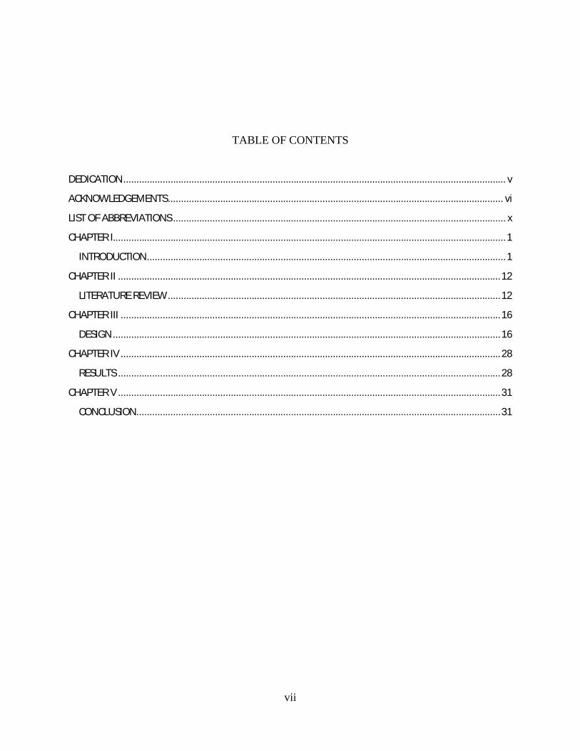
TABLE OF CONTENTS
DEDICATION.................................................................................................................................................. v
ACKNOWLEDGEMENTS................................................................................................................................ vi
LIST OF ABBREVIATIONS ............................................................................................................................... x
CHAPTER I......................................................................................................................................................1
INTRODUCTION.........................................................................................................................................1
CHAPTER II ..................................................................................................................................................12
LITERATURE REVIEW...............................................................................................................................12
CHAPTER III .................................................................................................................................................16
DESIGN ....................................................................................................................................................16
CHAPTER IV .................................................................................................................................................28
RESULTS ..................................................................................................................................................28
CHAPTER V ..................................................................................................................................................31
CONCLUSION...........................................................................................................................................31
viii
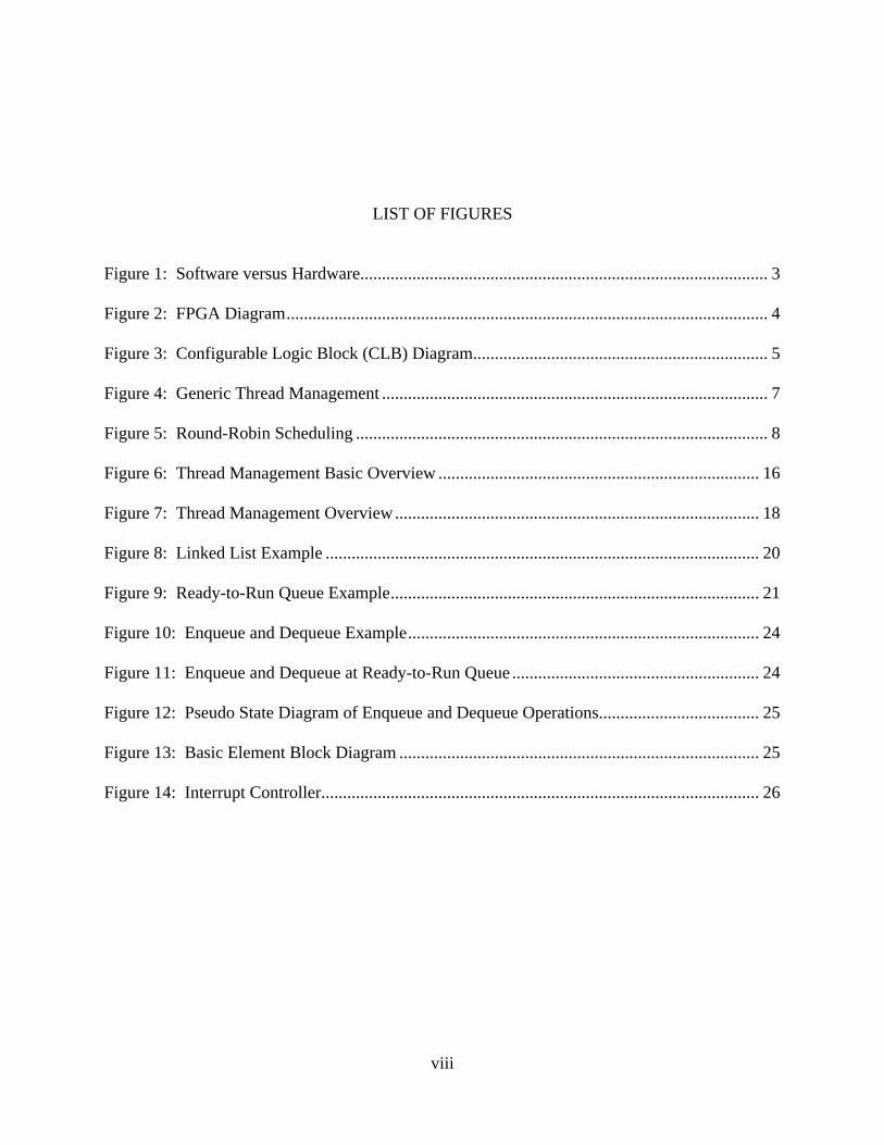
LIST OF FIGURES
Figure 1: Software versus Hardware.............................................................................................. 3
Figure 2: FPGA Diagram............................................................................................................... 4
Figure 3: Configurable Logic Block (CLB) Diagram.................................................................... 5
Figure 4: Generic Thread Management ......................................................................................... 7
Figure 5: Round-Robin Scheduling ............................................................................................... 8
Figure 6: Thread Management Basic Overview .......................................................................... 16
Figure 7: Thread Management Overview.................................................................................... 18
Figure 8: Linked List Example .................................................................................................... 20
Figure 9: Ready-to-Run Queue Example..................................................................................... 21
Figure 10: Enqueue and Dequeue Example................................................................................. 24
Figure 11: Enqueue and Dequeue at Ready-to-Run Queue ......................................................... 24
Figure 12: Pseudo State Diagram of Enqueue and Dequeue Operations..................................... 25
Figure 13: Basic Element Block Diagram ................................................................................... 25
Figure 14: Interrupt Controller..................................................................................................... 26
ix
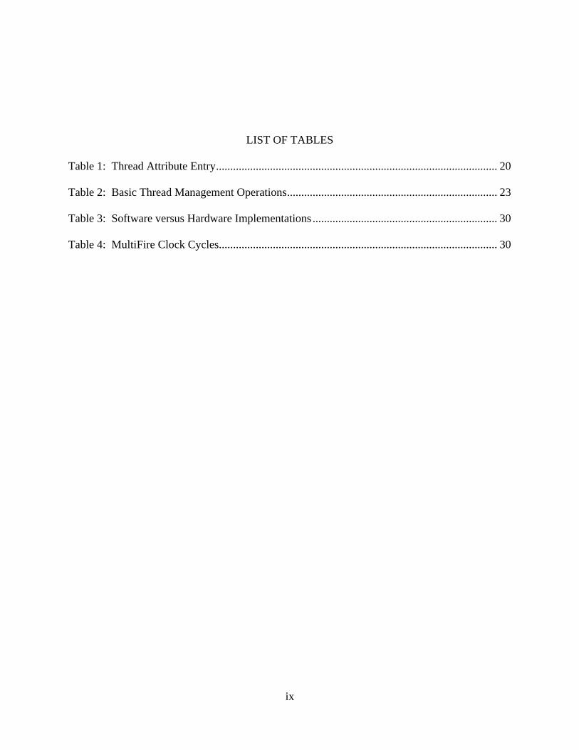
LIST OF TABLES
Table 1: Thread Attribute Entry................................................................................................... 20
Table 2: Basic Thread Management Operations.......................................................................... 23
Table 3: Software versus Hardware Implementations ................................................................. 30
Table 4: MultiFire Clock Cycles.................................................................................................. 30
x
LIST OF ABBREVIATIONS
API, Application Programming Interface
ASIC, Application Specific Integrated Circuit
BRAM, Block RAM
CPS, Cyber Physical Systems
FIFO, First-In First-Out
FPGA, Field Programmable Gate Array
FSM, Finite State Machine
HDL, Hardware Description Language
IPC, Inter-Process Communication
ISR, Interrupt Service Routine
POSIX, Portable Operating System Interface for UNIX
PRET, Precision Timed
RAM, Random Access Memory
RISC, Reduced Instruction Set Computing
RTOS, Real Time Operating System
VHDL, Very-High-Speed Integrated Circuits Hardware Description Language
1
CHAPTER I
INTRODUCTION
Research advances in Cyber Physical Systems (CPS) promise to transform our world
with systems that respond more quickly, are more precise, work in dangerous or inaccessible
environments, provide large-scale, distributed coordination, are highly efficient, augment human
capabilities, and enhance societal wellbeing. Some examples include autonomous collision
avoidance; robotic surgery and nano-tolerance manufacturing; autonomous systems for search
and rescue; firefighting, and exploration, automated traffic control; zero-net energy buildings;
and assistive technologies and ubiquitous healthcare monitoring and delivery [1]. CPS is
essentially the conjoining and coordination of physical and computational resources. However,
current computing and networking abstractions are not well suited for implementing CPS
applications [2]. New abstractions must be developed to incorporate computing and physical
processes in a unified way.
Current methods for computing, networking, and implementing software focus more on
average case performance rather than timing predictability. Programming languages such as C
or Java have no methods to specify timing constraints. That is, the language does not associate
timing with a program. Typically, system components are designed individually and later
integrated. In the end, worst-case execution time can be calculated and addressed. While current
architectures that employ multi-level caches, branch predictors, deep pipelines, etc improve
average case performance, they do not affect worst-case performance [3]. Failures in certain
2
applications that rely on worst-case execution times could be catastrophic, such as flight
controllers for satellites, medical diagnostics equipment for a patient in intensive care, and
guidance systems for missiles to name a few. CPS is primarily concerned with how time is
addressed. In the physical world, time cannot pause in order to perform calculations, and CPS
must operate in real-time in order to adhere to the fact that time is continuous in the physical
world. In an effort to achieve the timing requirements of CPS, new processor architectures have
been identified to include Precision Timed (PRET) processors.
PRET aims to address timing predictability at the architecture level. Timing
predictability is the ability to predict timing properties of the system [3]. Many of the basic
elements of a RISC processor are kept while removing other sources of indeterminacy.
Conceptually, instructions are fetched, decoded, and executed the same way; however, methods
for implementing these tasks can vary. For CPS research, an open source PRET processor is
being developed based on the OpenFire soft processor [4]. While many aspects of a processor
that affect the execution of tasks can be addressed, such as pipelines, caches, inter-process
communications (IPC), and resource allocation, thread management is addressed in this thesis.
More specifically, hardware and software interfacing for the scheduling of threads is addressed.
Different methods for implementing hardware schedulers are indentified, modeled, and analyzed.
Motivations behind implementing a hardware management controller include: speedup over
software, flexibility, and performance gains directly rated to frequency of scheduling operation
(to name a few).
Other than their names, differences exist between software and hardware. Software can
be thought of as a set of ordered instructions required to perform a specific task. These
instructions can be a source of overhead, especially in real-time systems. If a patient’s blood

3
pressure significantly drops; but, ten instructions must be performed in order to alert the nurse,
vital time has been wasted if the instructions take a considerably long time to execute. Hardware
can potentially overcome a lot of pitfalls associated with software. Some calculations can be
performed in parallel with a CPU if implemented in hardware. Overhead is reduced by not
performing a set of instructions. Moreover, hardware is inherently deterministic. That is,
execution times in hardware can more easily be calculated when compared to execution times in
software. Figure 1 [5] illustrates an example between software and hardware implementing the
same algorithm. While the software version can execute the algorithm in 12 clock cycles,
additional overhead can exist; however, the hardware version takes 2 clock cycles with little to
no additional overhead.
Figure 1: Software versus Hardware
4
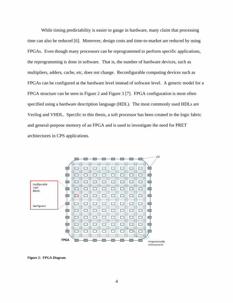
While timing predictability is easier to gauge in hardware, many claim that processing
time can also be reduced [6]. Moreover, design costs and time-to-market are reduced by using
FPGAs. Even though many processors can be reprogrammed to perform specific applications,
the reprogramming is done in software. That is, the number of hardware devices, such as
multipliers, adders, cache, etc, does not change. Reconfigurable computing devices such as
FPGAs can be configured at the hardware level instead of software level. A generic model for a
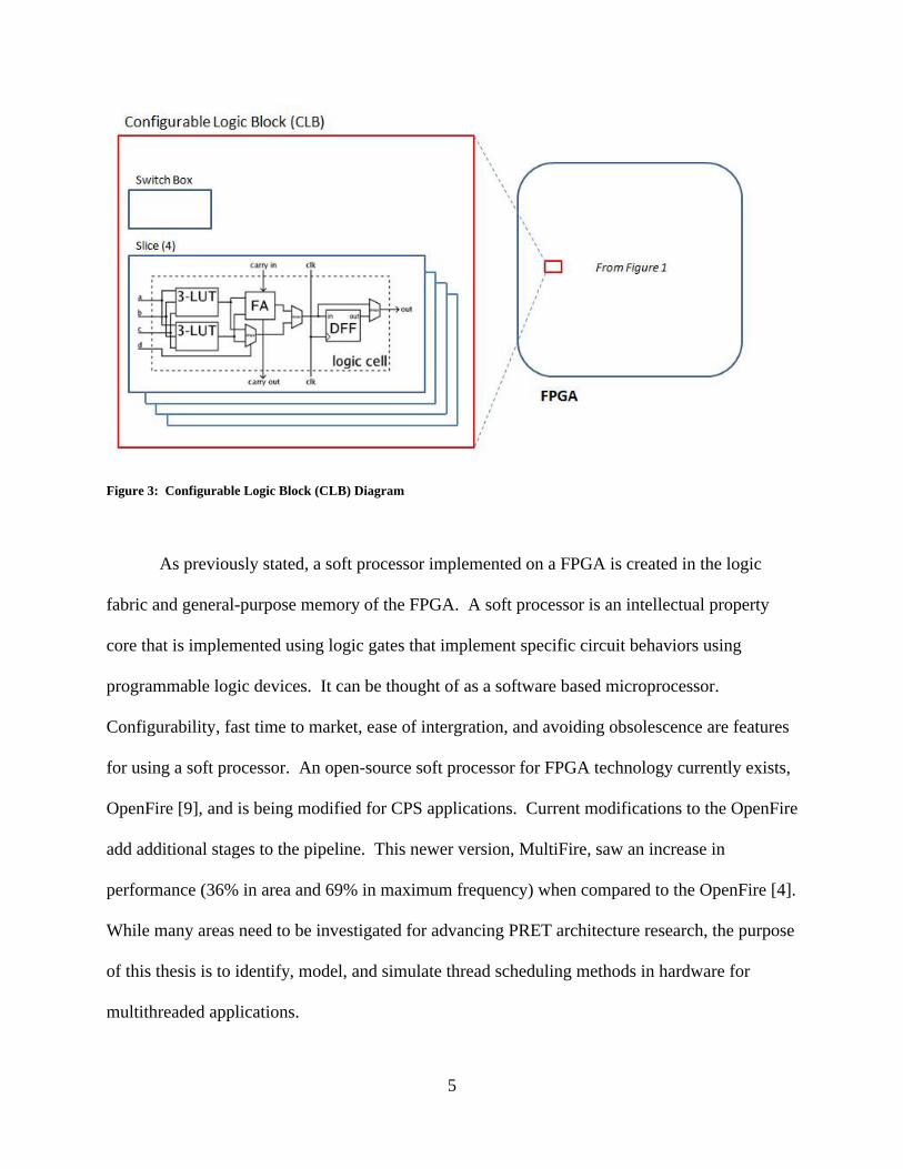
FPGA structure can be seen in Figure 2 and Figure 3 [7]. FPGA configuration is most often
specified using a hardware description language (HDL). The most commonly used HDLs are
Verilog and VHDL. Specific to this thesis, a soft processor has been created in the logic fabric
and general-purpose memory of an FPGA and is used to investigate the need for PRET
architectures in CPS applications.
Figure 2: FPGA Diagram
5
Figure 3: Configurable Logic Block (CLB) Diagram
As previously stated, a soft processor implemented on a FPGA is created in the logic
fabric and general-purpose memory of the FPGA. A soft processor is an intellectual property
core that is implemented using logic gates that implement specific circuit behaviors using
programmable logic devices. It can be thought of as a software based microprocessor.
Configurability, fast time to market, ease of intergration, and avoiding obsolescence are features
for using a soft processor. An open-source soft processor for FPGA technology currently exists,
OpenFire [9], and is being modified for CPS applications. Current modifications to the OpenFire
add additional stages to the pipeline. This newer version, MultiFire, saw an increase in
performance (36% in area and 69% in maximum frequency) when compared to the OpenFire [4].
While many areas need to be investigated for advancing PRET architecture research, the purpose
of this thesis is to identify, model, and simulate thread scheduling methods in hardware for
multithreaded applications.
6
Threads are essentially a set of instructions used to carry-out a specific operation. What
is more, multithreading is the process of executing multiple threads on a processor as
concurrently as possible. Certain tasks in the physical world are made up of multiple processes
that can run in parallel. For example, an autonomous system might interpret speed, temperature,
height, and pressure in order to make a decision for a specified task. Each event measured can
be considered a thread. That is, the instructions needed to make a speed measurement will be
accomplished using one thread, and the instructions needed to make a temperature measurement
will be accomplished on another thread. While correctness is important, performing these tasks
correctly in real-time is paramount. Specific events in the applications environment determine
thread significance. In the example above, measuring temperature may be more critical than
measuring speed. Moreover, speed may be measured more often that temperature. Therefore,
when temperature is needed, the thread providing temperature data may need to interrupt the
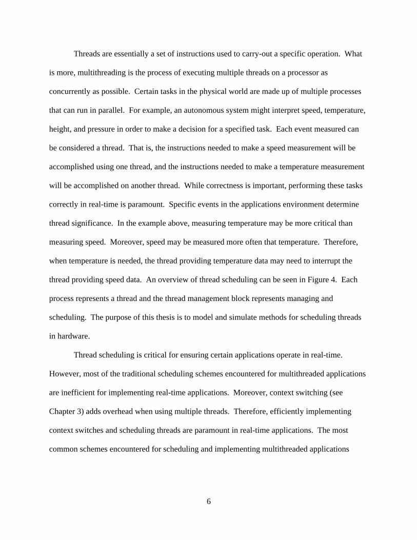
thread providing speed data. An overview of thread scheduling can be seen in Figure 4. Each
process represents a thread and the thread management block represents managing and
scheduling. The purpose of this thesis is to model and simulate methods for scheduling threads
in hardware.
Thread scheduling is critical for ensuring certain applications operate in real-time.
However, most of the traditional scheduling schemes encountered for multithreaded applications
are inefficient for implementing real-time applications. Moreover, context switching (see
Chapter 3) adds overhead when using multiple threads. Therefore, efficiently implementing
context switches and scheduling threads are paramount in real-time applications. The most
common schemes encountered for scheduling and implementing multithreaded applications
7
include: round-robin, first-in first-out (FIFO), shortest time remaining, multilevel queue, and
priority based scheduling.
Figure 4: Generic Thread Management
Current implementation in the MultiFire processor employs a round-robin scheduling
scheme; a new instruction is fetched each cycle from a different thread. Round-robin is
considered the simplest solution for implementing a thread scheduling algorithm. Equal time-
slices are given to each thread and they cycle through the pipeline in a circular fashion [10].
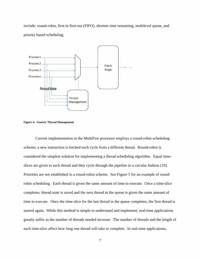
Priorities are not established in a round-robin scheme. See Figure 5 for an example of round-
robin scheduling. Each thread is given the same amount of time to execute. Once a time-slice
completes, thread state is saved and the next thread in the queue is given the same amount of
time to execute. Once the time-slice for the last thread in the queue completes, the first thread is
started again. While this method is simple to understand and implement, real-time applications
greatly suffer as the number of threads needed increase. The number of threads and the length of
each time-slice affect how long one thread will take to complete. In real-time applications,
8
certain threads may require earlier completion times. While dividing the time equally to execute
each thread might seem fair, certain applications might need attention and results sooner. For
example, if someone’s heart stops beating who is wearing a pacemaker, immediate attention
should be given to the circuitry required to keep the person’s heart beating. Therefore, more
time (i.e. longer time-slices) for certain threads might be needed. Three other traditional
scheduling methods (first-in first-out, shortest remaining time, and fixed priority) exist to address
the inefficiencies seen in round-robin scheduling schemes. However, they too are sometimes
inefficient for implementing real-time applications.
Figure 5: Round-Robin Scheduling
In a broad sense, first-in first-out (FIFO) is a concept that allows the first element
encountered of a process to be serviced. Some examples include: people waiting in line, a print
queue, and electronic buffers. Think of standing in line at a place of business. The person in
9
front of the line is serviced first. After they are serviced, the next person in line is serviced. This
process is repeated until all people have been serviced. The same idea can be seen in a standard
print queue. If five people want to print a document at the same time, whoever gives their
document to the print queue first will be serviced first regardless of the size of the document.
The first document could consist of one hundred pages while the next document in the queue
could consist of one page. Regardless, the first document in the print queue will be serviced
first. While this method seems the most fair, it proves very inefficient for real-time applications.
Throughput is typically low due to long processes filling the queue. Moreover, deadlines are not
addressed when executing processes. However, scheduling overhead is typically minimal since
context switching only occurs at process termination.
Shortest remaining time scheduling, sometimes called shortest job first, is a concept that
allows a process with the shortest time to be serviced first. The same example of standing in line
can be used for illustration. When two people enter a line at a business, occasionally the person
needing more time allows the other person needing shorter time to be serviced first. For
example, occasionally a customer at a grocery store with a cart full of groceries will allow for
another person with one item to be serviced first. This easily proves subjective depending on the
people involved. Moreover, a real-time application implementing a shortest remaining time
scheduling scheme is not subjective. While a person can easily make their plea to move to the
front of the line, threads do not have this luxury. A processor does not know the difference
between a thread servicing a patient in the hospital and a thread reading a thermometer. This
method proves inefficient in a lot of ways. First, processes with longer times suffer. They
constantly must wait for shorter processes to complete before being considered. The longer
processes are effectively starved of processor time. Second, context switching adds overhead if a
10
currently running process is interrupted by a process with shorter time. If this happens, the
longer process is split in half, potentially many times, allowing for shorter processes to execute.
Last, deadlines are not considered. The processing time is simply addressed and considered
when determining which process to execute. In order to introduce some form of subjectivity to
determine which thread is serviced first, a fixed priority pre-emptive scheduling scheme can be
implemented.
Fixed priority pre-emptive scheduling is a concept that applies priorities to processes to
determine their order for being serviced. A thread with a higher priority will move up in the run
queue. If it is blocked, it will move to a wait queue and the next highest priority thread will be
executed in the run queue. Determining the priority for each thread depends on the application.
For this report, scheduling priority based threads in hardware will be addressed. Moreover, it is
assumed that priorities have already been established for the purpose of this report. That is,
prioritizing threads is not of concern for the purpose of this report; however, it is addressed in
Chapters 4 and 5. For the purpose of this report, four priorities will be used. The highest three
priorities are used for application specific operations, and the fourth priority is used for an idle
state. Priorities are needed in order to address the hierarchy of events for a specific process. For
example, if a pacemaker senses that the user’s heart stops beating, the process needed for starting
the user’s heart should have highest priority. Moreover, other threads should be halted when this
process is needed. For example, if the user’s temperature is being measured, it should be halted
to allow the process servicing the user’s heart activity to run.
Real time operating systems (RTOS) are closely related to PRET architectures and
processors. While both are concerned with time, the main difference is that RTOS has minimal
interrupt latency where PRET processors must have zero interrupt latency. Moreover, RTOSs
11
add unnecessary overhead making the execution non-deterministic. In a FPGA application, the
hardware portion would be synthesized on the FPGA and the software portion would be
performed through the RTOS. The interaction between hardware and software is accomplished
through the programming language, which is usually C [11].
Implementing a hardware thread management system on the MultiFire will attempt to
eliminate overhead commonly seen in software thread management systems. Moreover, a
hardware thread management system will attempt to meet the timing demands for CPS. A
design for a hardware thread scheduler will be modeled and compared to software thread
management techniques. Scenarios will be used for thread simulation; moreover, threads will
have one of four priorities associated with them and will have already been configured.
Chapter 1 introduces the reader to CPS, PRET architectures, Field Programmable Gate
Array (FPGA) technology, thread scheduling, and a need for hardware thread management on
the MultiFire. Chapter 2 presents literature for current and past research for thread management
techniques in both hardware and software. Chapter 3 presents the design methodology for
implementing a hardware thread management system on the MultiFire. Chapter 4 presents the
results when comparing a hardware thread management system to a software thread management
system. Chapter 5 presents a summary of findings and need for future work.
12
CHAPTER II
LITERATURE REVIEW
Timing predictability, or determinacy, is difficult to calculate for software. However, it
is much easier for hardware. That is, when writing code for a program, it is difficult to calculate
how much time the code needs to execute. However, one can more easily predict timing in
hardware. Flops, registers, logic gates, etc can easily produce a timing diagram; or, a timing
diagram can easily be generated for hardware. Therefore, implementing a specific method for
managing and scheduling threads in hardware versus software seems most logical. While thread
management for PRET architectures is not fully developed, RTOS thread management
techniques aid with PRET thread management development. Moreover, thread management
techniques in hardware assist in the development of PRET thread management. Scheduling,
dispatching, IPC, and synchronization are key features of thread management. Scheduling
involves determining which process executes; dispatching involves the actual execution of each
process; IPC and synchronization assures that each process cooperates with each other using
mutexes, semaphores, messages, etc. Current research investigating the need for PRET
architectures and CPS exists at numerous universities, most notably Berkley [12] [13] and
Vanderbilt University Institute for Software Integrated Systems [14].
Hardware based thread schedulers are not a new concept as seen in [15-23]. Agron [15]
[21], Peck [17], and Finley [18] propose a system that uses one thread table in the scheduler.
Moreover, scheduling decisions are made using this table and a 128:32 priority encoder which
13
calculates the highest priority thread within the thread table. Our system differs by proposing the
use of multiple ready-to-run queues, or priority queues, as linked lists based on priority. That is,
each ready-to-run queue represents a priority. This also addresses the issue of multiple threads
with the same priority. If one queue was used, sorting the queue to make scheduling decisions
would add overhead to the scheduler. Implementing multiple queues based on priority
eliminates this overhead.
Kuacharoen [16] proposes that their thread scheduler use one priority queue for
preemptive scheduling. Moreover, the priority queue is to sort and order itself when a thread is
added or removed. To eliminate the need of sorting and ordering a list in hardware, which would
potentially create timed indeterminacy, our system proposes the use of a number of ready-to-run
queues equaling the number of priorities are implemented as linked lists. Sorting and re-ordering
each time a thread is added to a queue in hardware can be complex; therefore, a number of
ready-to-run queues equaling the number of priorities are implemented as linked lists.
Lee and Daleby [19] propose a hardware RTOS unit called a real-time unit (RTU). This
device is comprised of units: scheduler, message passing, interrupt handler, real-time control, an
accelerator interface, and a technology dependent bus interface. Moreover, custom applications
programming interfaces (API) are used to interface with OS services. Their intent is to be
modular, occupy little space, and facilitate interfacing with other busses. Our system utilizes the
Portable Operating System Interface for UNIX (POSIX) thread standard, pthreads, which
eliminates the need for custom APIs interfacing with OS services. That is, POSIX thread
compatible APIs can be used. To facilitate bus interfacing, MultiFire uses one of the same bus
standards as MicroBlaze. The primary I/O bus is a traditional system-memory mapped bus with
14
master and slave capability. MultiFire accesses local memory, BlockRAM (BRAM), directly,
which is discussed in Chapter 3.
Silva [20] proposes a system that operates based on asynchronous and synchronous
events. These events in addition to task state provided by a general register function together in
order to send information to the scheduler. When either type of event occurs, its thread ID is
sent to the scheduler as a ready-to-run task. While tasks in this system have priorities, multiple
priorities do not exist. That is, no two tasks can have the same priority. The tasks are essentially
ranked according to the number of tasks present in the system. Our system incorporates pre-
emptive scheduling in which multiple tasks can have the same priority. Moreover, tasks that are
ready to run are placed in their respective ready-to-run queue based on priority.
Lu [22] presents a generic design for thread management. Their multithreaded system is
managed by thread state in addition to instruction decoding. Their goals are reduced overhead,
low context switching penalty, and maintaining single thread performance. By decoding the
current instruction and tracking the status of execution and memory access stages, the next
thread can be decided using arbitration logic. As the name implies, the arbiter decides which of
the many processes seeking access to execute is allowed to execute. Moreover, their design does
not address threads with priorities. The decision made in their design is only based on thread
state and instruction decoding. Our system differs in that priorities determine which thread is
executed next. Moreover, instruction operands and memory status does not affect the scheduling
process. The complexity of arbitration logic may be excessive for applications with few threads
and few instructions.
Lindh [23] proposes a Fast Time Deterministic HARDware based real-time kernel
(FASTHARD). This design claims to support 256 tasks, 8 priorities, and operations for setting
15
the priority of a thread. In our system, 16 threads and 4 priorities are supported. Moreover,
priorities are established prior to run-time or upon thread creation. Once a priority has been
established it is not changed; however, future work could address the need for dynamic priorities
during runtime.
For the purpose of this thesis, certain assumptions will be made about the system. For
example, thread state will be provided to hardware in order to determine which thread is to be
executed. Therefore, thread state is produced in software. Moreover, prioritizing threads will be
accomplished in software. Specifically, one of the states for each thread includes priority.
Many of the same determinations in this thesis have been addressed in the others listed
above. Context switching overhead produced by a scheduling decision in software can be
eliminated by implementing the scheduling decision in hardware. The hardware scheduler can
be thought of as a coprocessor within the system. Interrupts and scheduling decisions can be
handled within this coprocessor (hardware scheduler). Scheduling decisions in hardware can be
made prior to interrupts; moreover, better timing predictability can be me made of interrupts
without impacting the timing of other executing threads. The implementation of the hardware
based thread scheduler is that of a finite state machine (FSM); furthermore, a fixed number of
clock cycles can be predetermined for the hardware scheduler meeting the needs of PRET
architecture and CPS applications.
16
CHAPTER III
DESIGN
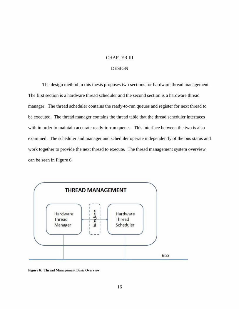
The design method in this thesis proposes two sections for hardware thread management.
The first section is a hardware thread scheduler and the second section is a hardware thread
manager. The thread scheduler contains the ready-to-run queues and register for next thread to
be executed. The thread manager contains the thread table that the thread scheduler interfaces
with in order to maintain accurate ready-to-run queues. This interface between the two is also
examined. The scheduler and manager and scheduler operate independently of the bus status and
work together to provide the next thread to execute. The thread management system overview
can be seen in Figure 6.
Figure 6: Thread Management Basic Overview
17
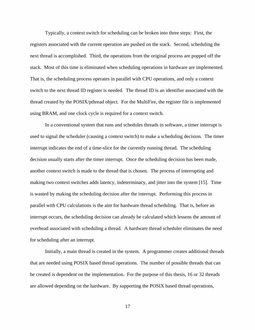
Typically, a context switch for scheduling can be broken into three steps: First, the
registers associated with the current operation are pushed on the stack. Second, scheduling the
next thread is accomplished. Third, the operations from the original process are popped off the
stack. Most of this time is eliminated when scheduling operations in hardware are implemented.
That is, the scheduling process operates in parallel with CPU operations, and only a context
switch to the next thread ID register is needed. The thread ID is an identifier associated with the
thread created by the POSIX/pthread object. For the MultiFire, the register file is implemented
using BRAM, and one clock cycle is required for a context switch.
In a conventional system that runs and schedules threads in software, a timer interrupt is
used to signal the scheduler (causing a context switch) to make a scheduling decision. The timer
interrupt indicates the end of a time-slice for the currently running thread. The scheduling
decision usually starts after the timer interrupt. Once the scheduling decision has been made,
another context switch is made to the thread that is chosen. The process of interrupting and
making two context switches adds latency, indeterminacy, and jitter into the system [15]. Time
is wasted by making the scheduling decision after the interrupt. Performing this process in
parallel with CPU calculations is the aim for hardware thread scheduling. That is, before an
interrupt occurs, the scheduling decision can already be calculated which lessens the amount of
overhead associated with scheduling a thread. A hardware thread scheduler eliminates the need
for scheduling after an interrupt.
Initially, a main thread is created in the system. A programmer creates additional threads
that are needed using POSIX based thread operations. The number of possible threads that can
be created is dependent on the implementation. For the purpose of this thesis, 16 or 32 threads
are allowed depending on the hardware. By supporting the POSIX based thread operations,
18
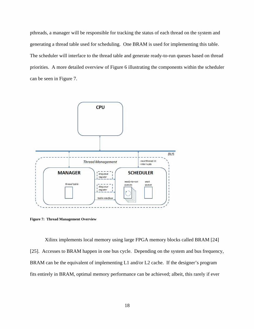
pthreads, a manager will be responsible for tracking the status of each thread on the system and
generating a thread table used for scheduling. One BRAM is used for implementing this table.
The scheduler will interface to the thread table and generate ready-to-run queues based on thread
priorities. A more detailed overview of Figure 6 illustrating the components within the scheduler
can be seen in Figure 7.
Figure 7: Thread Management Overview
Xilinx implements local memory using large FPGA memory blocks called BRAM [24]
[25]. Accesses to BRAM happen in one bus cycle. Depending on the system and bus frequency,
BRAM can be the equivalent of implementing L1 and/or L2 cache. If the designer’s program
fits entirely in BRAM, optimal memory performance can be achieved; albeit, this rarely if ever
19
happens for a complex application. The BRAM block is configurable and able to attach to a
variety of BRAM Interface Controllers.
In order to conveniently identify the running time of a process or algorithm independent
of computer architecture or clock cycles, big-O notation is commonly used. It is typically used
to indicate an algorithm’s usage of computational resources. In this thesis, O(1) and O(n) are
used to indicate running times of the system. Specifically, they are used for the enqueueing and
dequeueing operations of the system. O(1) indicates a constant time whereas O(n) indicates the
operation is a function of the number, n, of items (i.e. threads), both of which are independent of
computer architecture or clock cycles.
Jitter is associated with scheduling threads in O(n) time. For example, if one ready-to-
run queue was used, a scheduling decision would require O(n) time for a sorted insert operation.
That is, the queue has to be traversed for scheduling decisions n times due to n threads.
Specifically, less time would be required for scheduling fewer threads. But, if the list of entries
grew, the time required to make a scheduling decision would also grow. The implementation of
multiple ready-to-run queues attempts to solve the jitter problem by making a scheduling
decision in O(1) time. In order to allow O(1) time for making a scheduling decision, ready-to-
run queues representing priorities are used. Moreover, by keeping the queues in FIFO order,
O(1) time can be accomplished. A pointer, in hardware, is used to point to the head of each
ready-to-run queue. Each thread contains a pointer that points to the next thread in the queue.
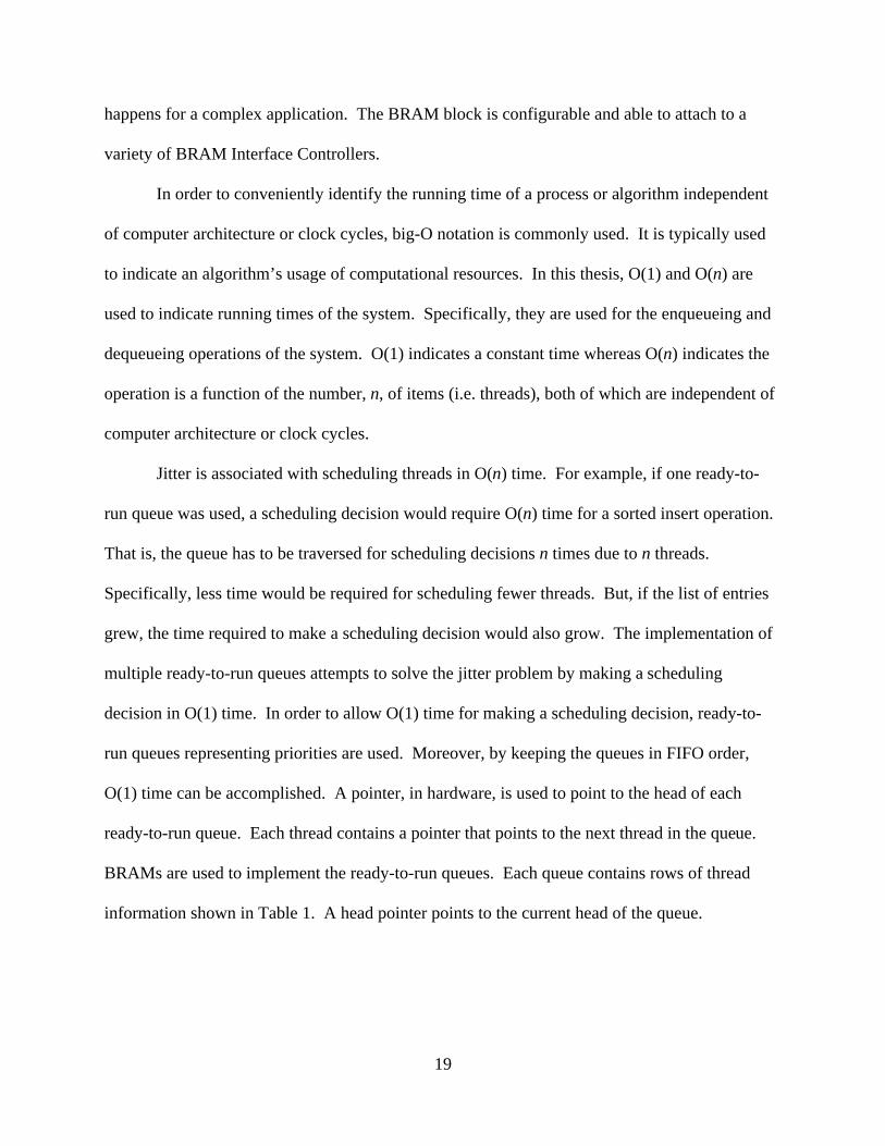
BRAMs are used to implement the ready-to-run queues. Each queue contains rows of thread
information shown in Table 1. A head pointer points to the current head of the queue.
20
Table 1: Thread Attribute Entry
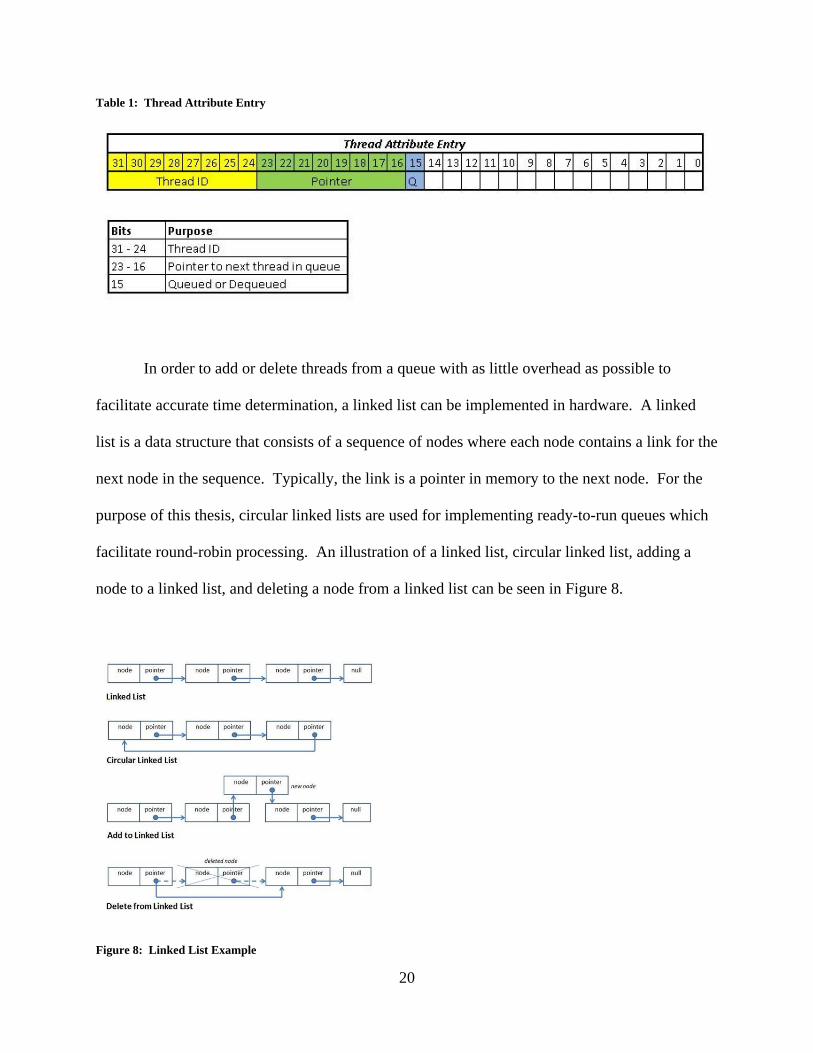
In order to add or delete threads from a queue with as little overhead as possible to
facilitate accurate time determination, a linked list can be implemented in hardware. A linked
list is a data structure that consists of a sequence of nodes where each node contains a link for the
next node in the sequence. Typically, the link is a pointer in memory to the next node. For the
purpose of this thesis, circular linked lists are used for implementing ready-to-run queues which
facilitate round-robin processing. An illustration of a linked list, circular linked list, adding a
node to a linked list, and deleting a node from a linked list can be seen in Figure 8.
Figure 8: Linked List Example
21
Implementing a linked list eliminates the need for sorting, which can be very complicated
in hardware. Moreover, implementing a priority based ready-to-run queue eliminates the need
for a sorted insert operation. That is, if one queue was used to store all ready-to-run threads, a
sorted insert operation would be needed each time a priority thread were added to the queue.
When one thread is removed, or blocked, deleting one element from a linked list allows for its
predecessor and successor to be linked together. Therefore, when the ready-to-run queue is
cycled through, clock cycles will not be lost due to an unfilled spot in the list.
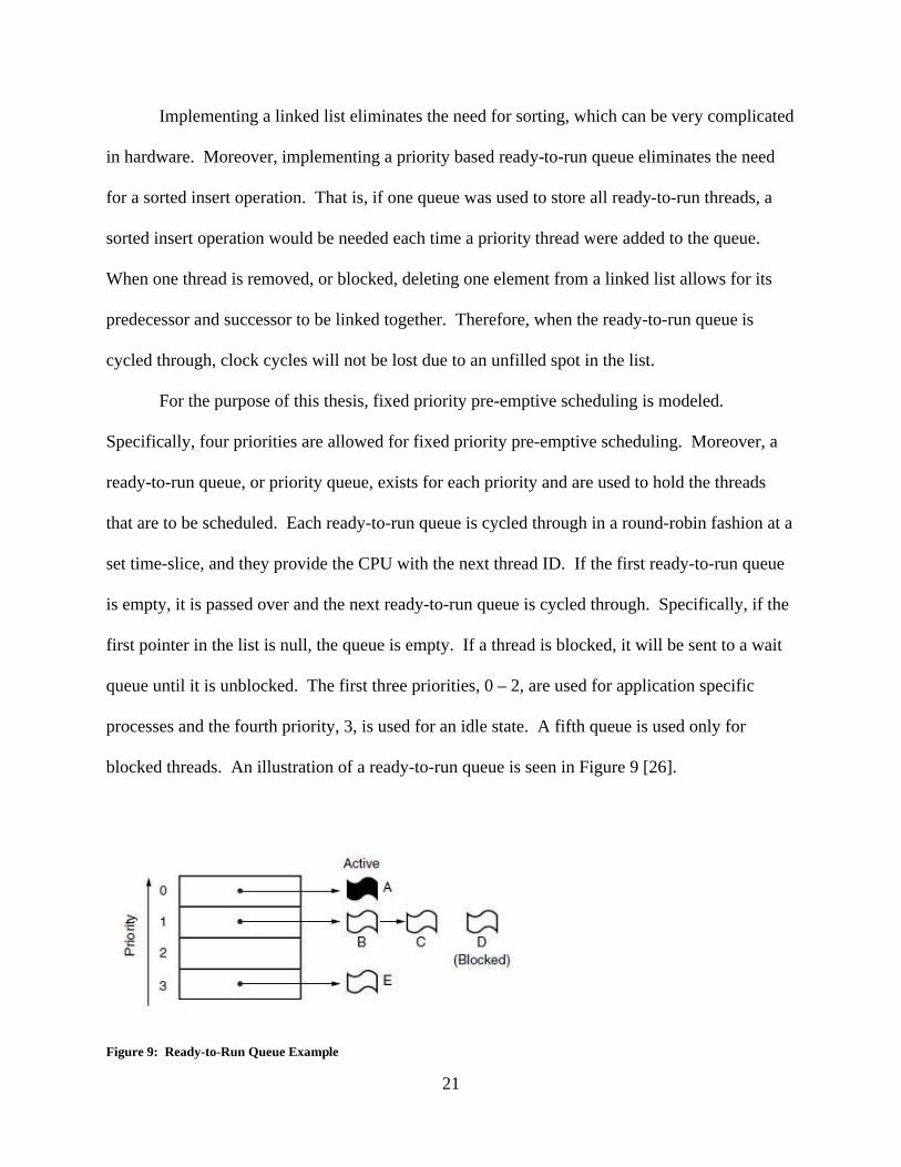
For the purpose of this thesis, fixed priority pre-emptive scheduling is modeled.
Specifically, four priorities are allowed for fixed priority pre-emptive scheduling. Moreover, a
ready-to-run queue, or priority queue, exists for each priority and are used to hold the threads
that are to be scheduled. Each ready-to-run queue is cycled through in a round-robin fashion at a
set time-slice, and they provide the CPU with the next thread ID. If the first ready-to-run queue
is empty, it is passed over and the next ready-to-run queue is cycled through. Specifically, if the
first pointer in the list is null, the queue is empty. If a thread is blocked, it will be sent to a wait
queue until it is unblocked. The first three priorities, 0 – 2, are used for application specific
processes and the fourth priority, 3, is used for an idle state. A fifth queue is used only for
blocked threads. An illustration of a ready-to-run queue is seen in Figure 9 [26].
Figure 9: Ready-to-Run Queue Example
22
In Figure 9, each ready-to-run queue is represented by the numbers 0 - 3 to the left of the
column. Each thread is represented by the letters A – E. Note that threads B – D have the same
priority. These will execute in a round-robin format. That is, the thread IDs for threads B – D
will be provided to the CPU in a round-robin format.
Depending on the events associated with the main program, additional threads can be
spawned from the main program. If the additional threads are needed, the thread manager
receives direction from the main program to add them to the system. The thread manager, using
the POSIX based thread API, adds a thread to the system and develops a thread table which is
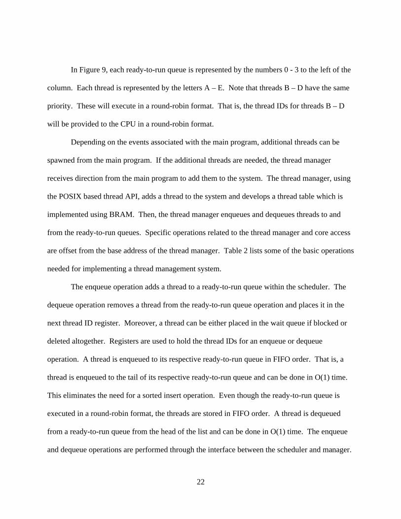
implemented using BRAM. Then, the thread manager enqueues and dequeues threads to and
from the ready-to-run queues. Specific operations related to the thread manager and core access
are offset from the base address of the thread manager. Table 2 lists some of the basic operations
needed for implementing a thread management system.
The enqueue operation adds a thread to a ready-to-run queue within the scheduler. The
dequeue operation removes a thread from the ready-to-run queue operation and places it in the
next thread ID register. Moreover, a thread can be either placed in the wait queue if blocked or
deleted altogether. Registers are used to hold the thread IDs for an enqueue or dequeue
operation. A thread is enqueued to its respective ready-to-run queue in FIFO order. That is, a
thread is enqueued to the tail of its respective ready-to-run queue and can be done in O(1) time.
This eliminates the need for a sorted insert operation. Even though the ready-to-run queue is
executed in a round-robin format, the threads are stored in FIFO order. A thread is dequeued
from a ready-to-run queue from the head of the list and can be done in O(1) time. The enqueue
and dequeue operations are performed through the interface between the scheduler and manager.
23
A thread will be only enqueued or dequeued from the tail or head, respectively, of a ready-to-run
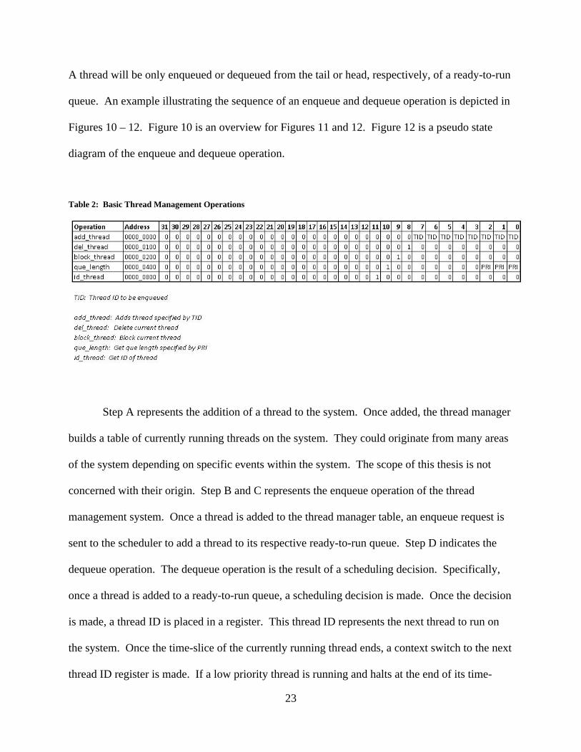
queue. An example illustrating the sequence of an enqueue and dequeue operation is depicted in
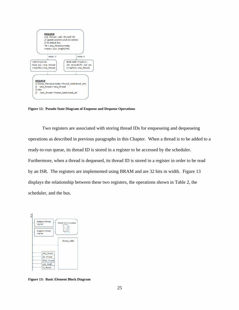
Figures 10 – 12. Figure 10 is an overview for Figures 11 and 12. Figure 12 is a pseudo state
diagram of the enqueue and dequeue operation.
Table 2: Basic Thread Management Operations
Step A represents the addition of a thread to the system. Once added, the thread manager
builds a table of currently running threads on the system. They could originate from many areas
of the system depending on specific events within the system. The scope of this thesis is not
concerned with their origin. Step B and C represents the enqueue operation of the thread
management system. Once a thread is added to the thread manager table, an enqueue request is
sent to the scheduler to add a thread to its respective ready-to-run queue. Step D indicates the
dequeue operation. The dequeue operation is the result of a scheduling decision. Specifically,
once a thread is added to a ready-to-run queue, a scheduling decision is made. Once the decision
is made, a thread ID is placed in a register. This thread ID represents the next thread to run on
the system. Once the time-slice of the currently running thread ends, a context switch to the next
thread ID register is made. If a low priority thread is running and halts at the end of its time-
24
slice, a context switch can be made to another other priority thread. Currently, only external
interrupts halt the currently running thread prior to the end of a time-slice. That is, if a higher
priority thread is scheduled to run next, it waits until the end of the time-slice of the currently
running thread.
Figure 10: Enqueue and Dequeue Example
Figure 11: Enqueue and Dequeue at Ready-to-Run Queue
25
Figure 12: Pseudo State Diagram of Enqueue and Dequeue Operations
Two registers are associated with storing thread IDs for enqueueing and dequeueing
operations as described in previous paragraphs in this Chapter. When a thread is to be added to a
ready-to-run queue, its thread ID is stored in a register to be accessed by the scheduler.
Furthermore, when a thread is dequeued, its thread ID is stored in a register in order to be read
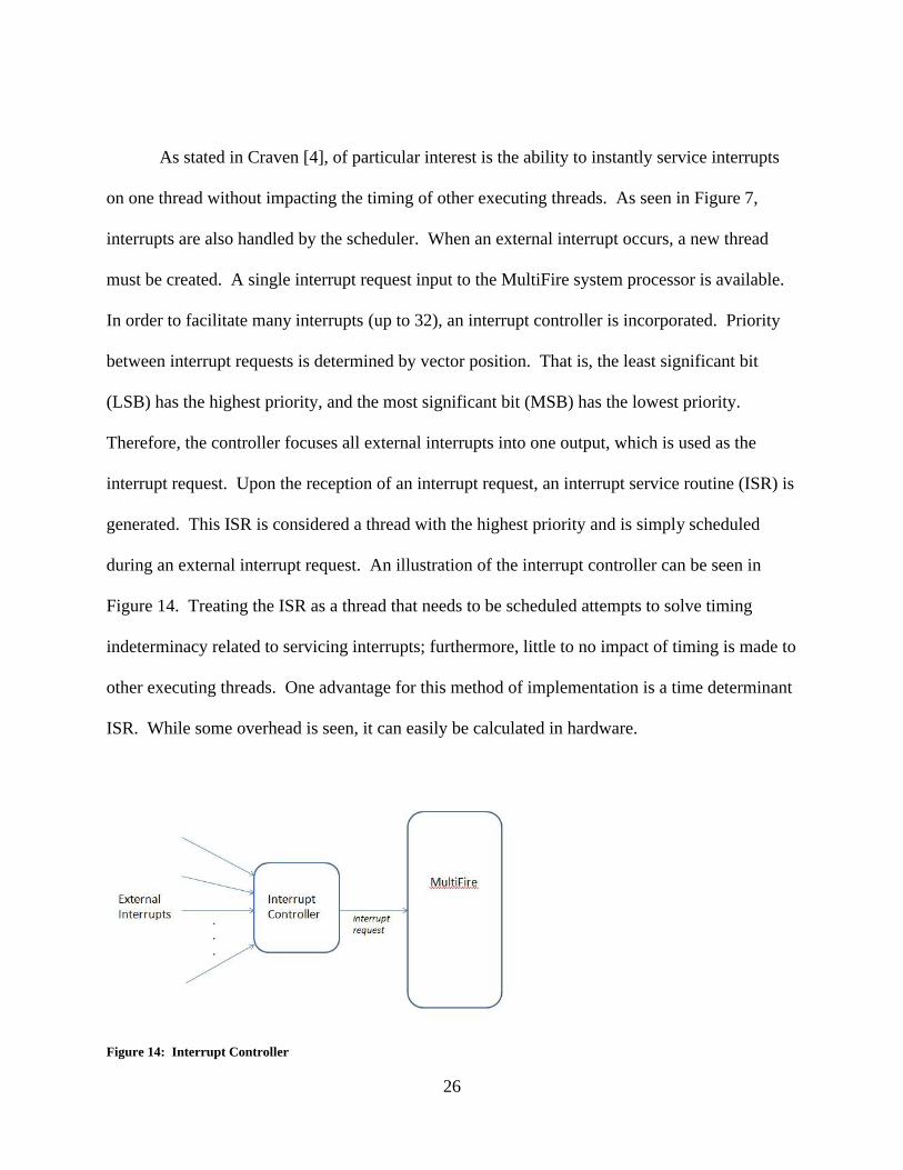
by an ISR. The registers are implemented using BRAM and are 32 bits in width. Figure 13
displays the relationship between these two registers, the operations shown in Table 2, the
scheduler, and the bus.
Figure 13: Basic Element Block Diagram
26
As stated in Craven [4], of particular interest is the ability to instantly service interrupts
on one thread without impacting the timing of other executing threads. As seen in Figure 7,
interrupts are also handled by the scheduler. When an external interrupt occurs, a new thread
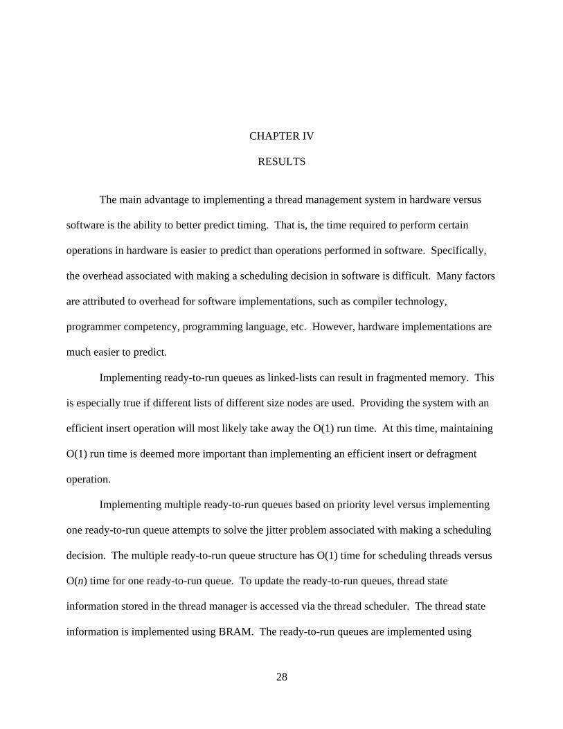
must be created. A single interrupt request input to the MultiFire system processor is available.
In order to facilitate many interrupts (up to 32), an interrupt controller is incorporated. Priority
between interrupt requests is determined by vector position. That is, the least significant bit
(LSB) has the highest priority, and the most significant bit (MSB) has the lowest priority.
Therefore, the controller focuses all external interrupts into one output, which is used as the
interrupt request. Upon the reception of an interrupt request, an interrupt service routine (ISR) is
generated. This ISR is considered a thread with the highest priority and is simply scheduled
during an external interrupt request. An illustration of the interrupt controller can be seen in
Figure 14. Treating the ISR as a thread that needs to be scheduled attempts to solve timing
indeterminacy related to servicing interrupts; furthermore, little to no impact of timing is made to
other executing threads. One advantage for this method of implementation is a time determinant
ISR. While some overhead is seen, it can easily be calculated in hardware.
Figure 14: Interrupt Controller
27
Both the thread manager and thread scheduler interface to the CPU via a memory-
mapped bus. That is, memory addresses will be used to define and access the scheduler and the
attributes associated with it. Certain operations can lock the bus; therefore, the manager and
scheduler interface through a set of registers directly. That is, the manager and scheduler operate
independently of the bus status. Registers indicating the currently running thread and the next
thread to run are needed. Moreover, an interface allowing the scheduler to access thread
information from the manger is also needed. Thread information in the manager is stored in
BRAM; therefore, the scheduler will need a port in order to access this information. This also
facilitates with time determinacy. Scheduling operations such as determining the priority of a
thread is accomplished via the bus interface.
28
CHAPTER IV
RESULTS
The main advantage to implementing a thread management system in hardware versus
software is the ability to better predict timing. That is, the time required to perform certain
operations in hardware is easier to predict than operations performed in software. Specifically,
the overhead associated with making a scheduling decision in software is difficult. Many factors
are attributed to overhead for software implementations, such as compiler technology,
programmer competency, programming language, etc. However, hardware implementations are
much easier to predict.
Implementing ready-to-run queues as linked-lists can result in fragmented memory. This
is especially true if different lists of different size nodes are used. Providing the system with an
efficient insert operation will most likely take away the O(1) run time. At this time, maintaining
O(1) run time is deemed more important than implementing an efficient insert or defragment
operation.
Implementing multiple ready-to-run queues based on priority level versus implementing
one ready-to-run queue attempts to solve the jitter problem associated with making a scheduling
decision. The multiple ready-to-run queue structure has O(1) time for scheduling threads versus
O(n) time for one ready-to-run queue. To update the ready-to-run queues, thread state
information stored in the thread manager is accessed via the thread scheduler. The thread state
information is implemented using BRAM. The ready-to-run queues are implemented using
29
linked lists. BRAMs require one clock cycle to write and read. Since the ready-to-run queue
structure has O(1) time for making scheduling operations, enqueueing and dequeueing require
one clock cycle.
Zero interrupt latency is achieved by allowing interrupts to be handled by the scheduler
directly. Treating the ISR as a thread needing to be scheduled attempts to solve timing
indeterminacy related to servicing interrupts; furthermore, little to no impact on timing is made
to other executing threads. A time determinant ISR is the outcome of this implementation.
One clock cycle is attributed with enqueueing a thread to the ready-to-run queue, which is what
is done when an ISR is scheduled. Furthermore, the number of threads running on the system
has no effect on the amount of time required for scheduling operations by implementing multiple
ready-to-run queues based on priority.
The number of cycles required for an associated thread or interrupt is affected by the
actual thread or interrupt itself. This variability is lessened by implementing the thread
management system in hardware versus software. According to Lee and Daleby [19],
approximately 536 cycles are necessary for a context switch related to a software scheduling
operation for one thread. Stergiou et al [27] claim that approximately 132 cycles are necessary
for context switching associated with an interrupt. Moreover, depending on the operation,
additional cycles can be encountered. The additional cycles are encountered from the CPU
interacting with memory. A hardware implementation reduces this time by keeping the memory
bus free from the CPU. Potdar [28] makes the claim that software scheduling time varies
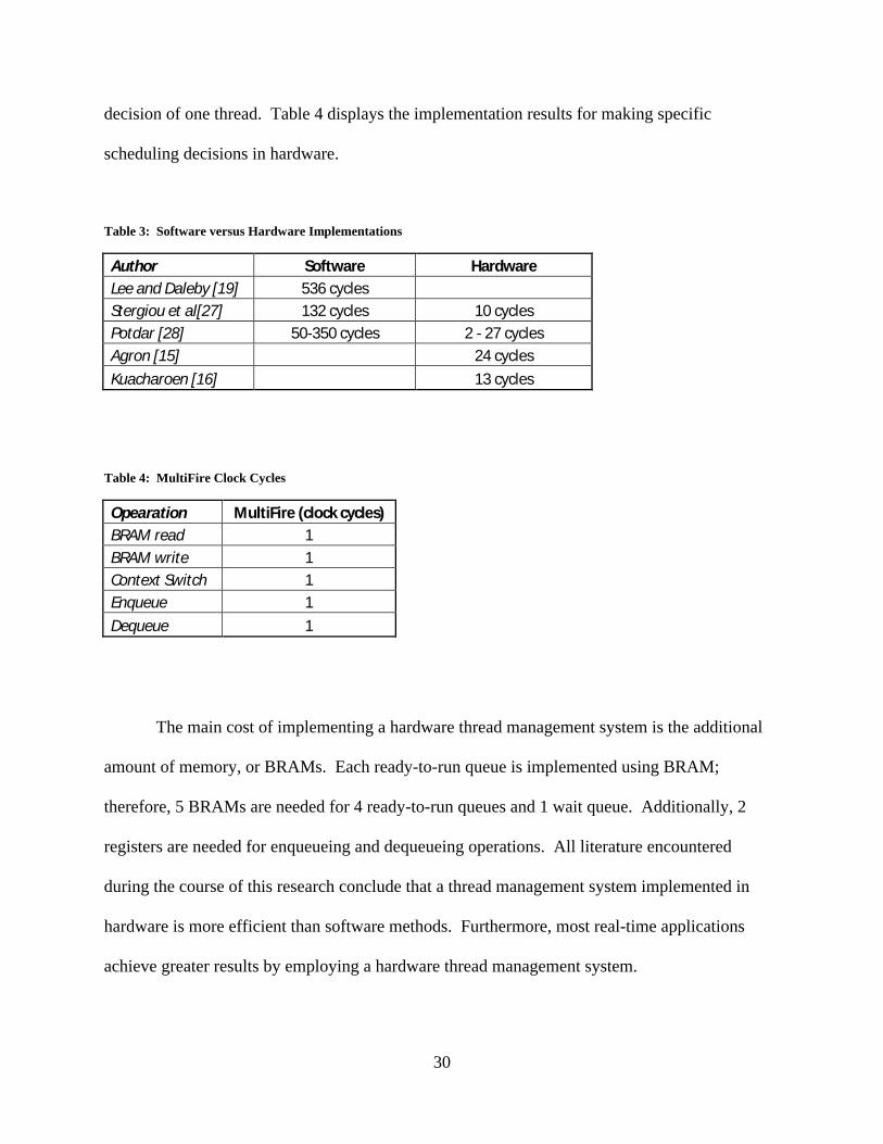
between 50 and 350 microseconds depending on the number of threads. Table 3 displays a
software implementation values versus hardware implementation values for making a scheduling
30
decision of one thread. Table 4 displays the implementation results for making specific
scheduling decisions in hardware.
Table 3: Software versus Hardware Implementations
Author Software HardwareLee and Daleby [19] 536 cyclesStergiou et al[27] 132 cycles 10 cyclesPotdar [28] 50-350 cycles 2 - 27 cyclesAgron [15] 24 cyclesKuacharoen [16] 13 cycles
Table 4: MultiFire Clock Cycles
Opearation MultiFire (clock cycles)BRAM read 1BRAM write 1Context Switch 1Enqueue 1Dequeue 1
The main cost of implementing a hardware thread management system is the additional
amount of memory, or BRAMs. Each ready-to-run queue is implemented using BRAM;
therefore, 5 BRAMs are needed for 4 ready-to-run queues and 1 wait queue. Additionally, 2
registers are needed for enqueueing and dequeueing operations. All literature encountered
during the course of this research conclude that a thread management system implemented in
hardware is more efficient than software methods. Furthermore, most real-time applications
achieve greater results by employing a hardware thread management system.
31
CHAPTER V
CONCLUSION
In summary, a hardware thread management system is more efficient than a software
thread management system. That is, a hardware implementation is time determinant for both
interrupts and normal threads. The manager and scheduler act primarily independent from the
rest of the system. That is, once the manager saves thread state information, the scheduler
accesses this information, adds threads to their respective ready-to-run queues, and provides the
next thread to run regardless the status of the bus. Implementing this in hardware facilitates time
determinacy. That is, the time required for reading data from BRAM, calculating cycles of a
state machine, and traversing linked lists can be calculated with high accuracy when
implemented in hardware.
Future work will include implementing a thread management scheme and comparing
theoretical results to actual results. Other considerations for future work include: cache
implementation and application development.
Implementing this model is the next important step in this design process. Much can be
learned by quantifying results from an implemented version. Moreover, improvements can be
made to this thesis by identifying any shortcomings and/or errors upon implementation.
Implementing cache will allow instructions to be accessed quicker, which is the main
reason why cache is implemented in all systems; that is, less time to access to data. Specifically,
if cache is implemented using BRAM, data can be written in one clock cycle and read in two
32
clock cycles. Moreover, replacement policies and associativity need to be identified. Certain
applications might require specific sizes with specific features in order to take advantage of
certain localities of reference (i.e. spatial or temporal).
Determining CPS based applications are a consideration for future work. To validate a
thread management scheme, or even a final proof concept, testing it with an actual application is
advantageous. That is, many lessons can be learned by investigating system behavior since
theory does not always match reality.
This thesis presents a model for implementing and understanding a hardware thread
management system. Zero interrupt latency and minimal thread scheduling time has been
addressed. Specifically, implementations attempting to meet O(1) time are the basis for
modeling in this thesis. Multiple ready-to-run queues based on priority permit this requirement.
Moreover, enqueueing and dequeueing threads in FIFO order permit this as well. The only cost
(the main cost) associated with implementing a hardware thread management system is space.
That is, the amount of memory, or BRAMs, is critical to the implementation. Based on the
research from others (as seen in Chapter 2) and the research gathered in this thesis, it is clear that
implementing a thread management system in hardware is more efficient than software.
33
REFERENCES CITED
[1] Cyber Physical Systems - US National Science Foundation (NSF), www.nsf.gov/funding/pgm_summ.jsp?pims_id=503286
[2] E. Lee (2008, Jan 23) Cyber Physical Systems: Design Challenges [Online]. Available: http://www.eecs.berkeley.edu/Pubs/TechRpts/2008/EECS-2008-8.html
[3] I. Liu, J. Reineke, E. Lee. "A PRET Architecture Supporting Concurrent Programs with Composable Timing Properties". 44th Asilomar Conference on Signals, Systems, andComputers, November, 2010.
[4] S. Craven, D. Long, and J. Smith, "Open Source Precision Timed Soft Processor for Cyber Physical System Applications," 2010.
[5] Xilinx Inc, “Connecting Customized IP to the MicroBlaze Soft Processor using the Fast Simplex Link (FSL) Channel,” ver 1.3, 2004
[6] FPGA Research - University of Toronto, http://www.eecg.toronto.edu/EECG/RESEARCH/FPGA.html
[7] Field Programmable Gate Array, http://en.wikipedia.org/wiki/Field-programmable_gate_array
[8] Xilinx Inc, Soft Processor Notes [Online]. Available: http://china.xilinx.com/ipcenter/processor_central/microblaze/doc/mb_faq.pdf
[9] OpenFire Project Page, http://openfirefpga.sourceforge.net/.
[10] F. Kon (2001, Apr 27) What is Round-Robin Scheduling? [Online]. Available: http://choices.cs.uiuc.edu/~f-kon/RoundRobin/node1.html
[11] S. Andalam, P. Roop, A. Girault, and C. Traulsen. PRET-C: A new language for programming precision timed architectures. Technical Report 6922, INRIA Grenoble Rhône-Alpes, 2009.
[12] Pret Timed (PRET) Machines, http://chess.eecs.berkeley.edu/pret/
[13] Edward Lee - University of California at Berkeley, http://ptolemy.eecs.berkeley.edu/~eal/
34
[14] Cyber Physical Systems – Vanderbilt University, http://www.isis.vanderbilt.edu/taxonomy/term/189
[15] J. Agron, D. Andrews, M. Finley, E. Komp, W. Peck, “FPGA Implementation of a Priority Scheduler Module,” In Proceedings of the 25th IEEE International Real-Time Systems Symposium, Works In Progress Session (RTSS, WIP 2004). Lisbon, Portugal, December 5-8, 2004.
[16] P. Kuacharoen, M. Shalan, V. Mooney III, “A Configurable Hardware Scheduler for Real-Time Systems,” in Proceedings of the International Conference on Engineering of Reconfigurable Systems and Algorithms (ERSA), 2003
[17] W. Peck, J. Agron, D. Andrews, M. Finley, E. Komp, “Hardware/Software Co-Design of Operating System Services for Thread Management and Scheduling,” In Proceedings of the 25th IEEE International Real-Time Systems Symposium, Works In Progress Session (RTSS, WIP 2004). Lisbon, Portugal, December 5-8, 2004.
[18] Michael Finley, “Hardware/Software Codesign: Thread Manager,” Master's Thesis at the University of Kansas (December, 2004).
[19] J. Lee , V. John , A. Daleby , K. Ingström , T. Klevin , L. Lindh , V. Mooney III, “A Comparison of the RTU Hardware RTOS with a Hardware/Software RTOS,” In Proceedings of the Asia and South Pacific Design Automation Conference (ASP-DAC), pages 683–688, Kitaskyushu International Conference, 2003
[20] E. Silva Jr., L. Carro, F. Wagner, C. Pereira, “Development of Multithread Real-Time Applications Using a Hardware Scheduler,” In Proceedings of 13th IFIP WG.10 VLSI-SoC'2005, Perth, Australia, October 2005, pp. 311--316.
[21] Jason Agron, “Run-Time Scheduling Support for Hybrid CPU/FPGA SoCs,” Master's Thesis at the University of Kansas (April, 2006).
[22] Y. Lu, S. Sezer, J. McCanny, “Advanced Multithreading Architecture with Hardware Based Thread Scheduling,” In Proceedings of the Field Programmable Logic and Applications (FPL), Belfast, U.K, 2010
[23] L. Lindh, “FASTHARD – A Fast Time Deterministic HARDware Based Real-Time Kernel,” IEEE press, Real-Time Workshop, Athens, January, 1992
[24] Xilinx Inc, “IP Processor Block Ram (BRAM) Block v1.00a,” 2011
[25] Xilinx Inc, “FPGA Embedded Processors: Revealing True System Performance,” 2005
[26] Xilinx Inc, “Xilkernel,“ ver 3, 2006
35
[27] Stergios Stergiou, A. Sotiropoulos, A. Alexandridi, and G. Manis. Rapid context switching on an fpga custom processor with a configurable number of registers. In IEEE International Workshop on System-On-Chip for Real-Time Applications, 2002.
[28] S. Potdar, “Hardware Based Scheduler for RTOS,” Master’s Thesis The University of Alabama, (Aug, 2008)
[29] J. Starner, J. Adomat, J. Furunas, L. Lindh, "Real-Time Scheduling Co-Processor in Hardware for Single and Multiprocessor Systems," euromicro, pp.0509, Proceedings of the 22nd EUROMICRO Conference, 1996
View publication statsView publication stats