Embed Size (px)
Citation preview
MEL 110: GRAPHIC SCIENCE Harish HiraniAssociate ProfessorBlock II/354. Dept of Mech. Eng.I.I.T Delhi
2-0-4Learn by Doing
Mon, ThursMinor I, 3.0Minor II, 2.0Last two weeks no lecture
MEL 110: GRAPHIC SCIENCE
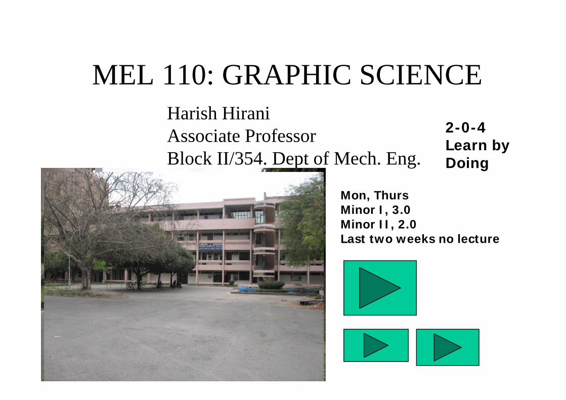
GRAPHICS: Art or Science of drawing
Systematic knowledge-base practice capable of resulting in predictable type of outcome.
Pr
RC
Pr
R
r
r
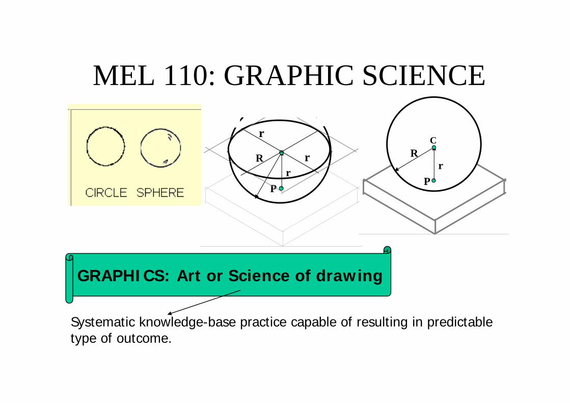
GRAPHICS: Art or Science of drawing
Systematic knowledge-base practice capable of resulting in predictable type of outcome.
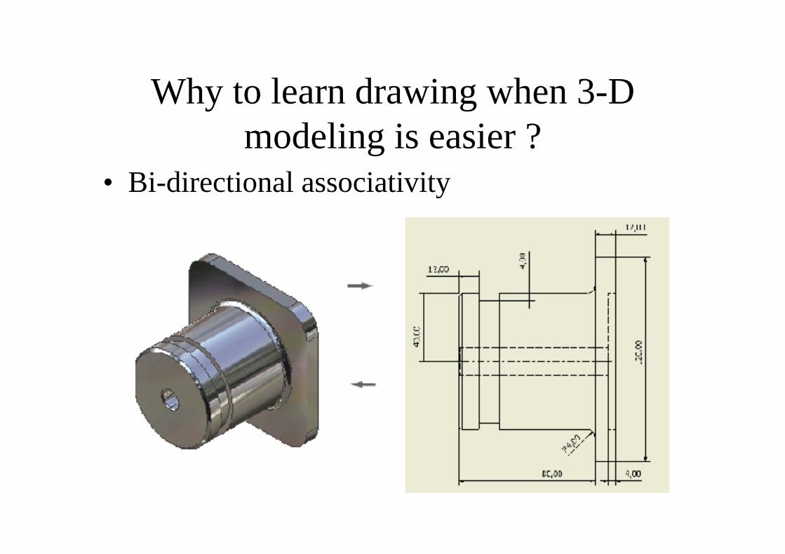
Why to learn drawing when 3-D modeling is easier ?
• Bi-directional associativity
Graphic images are more powerful than simple text
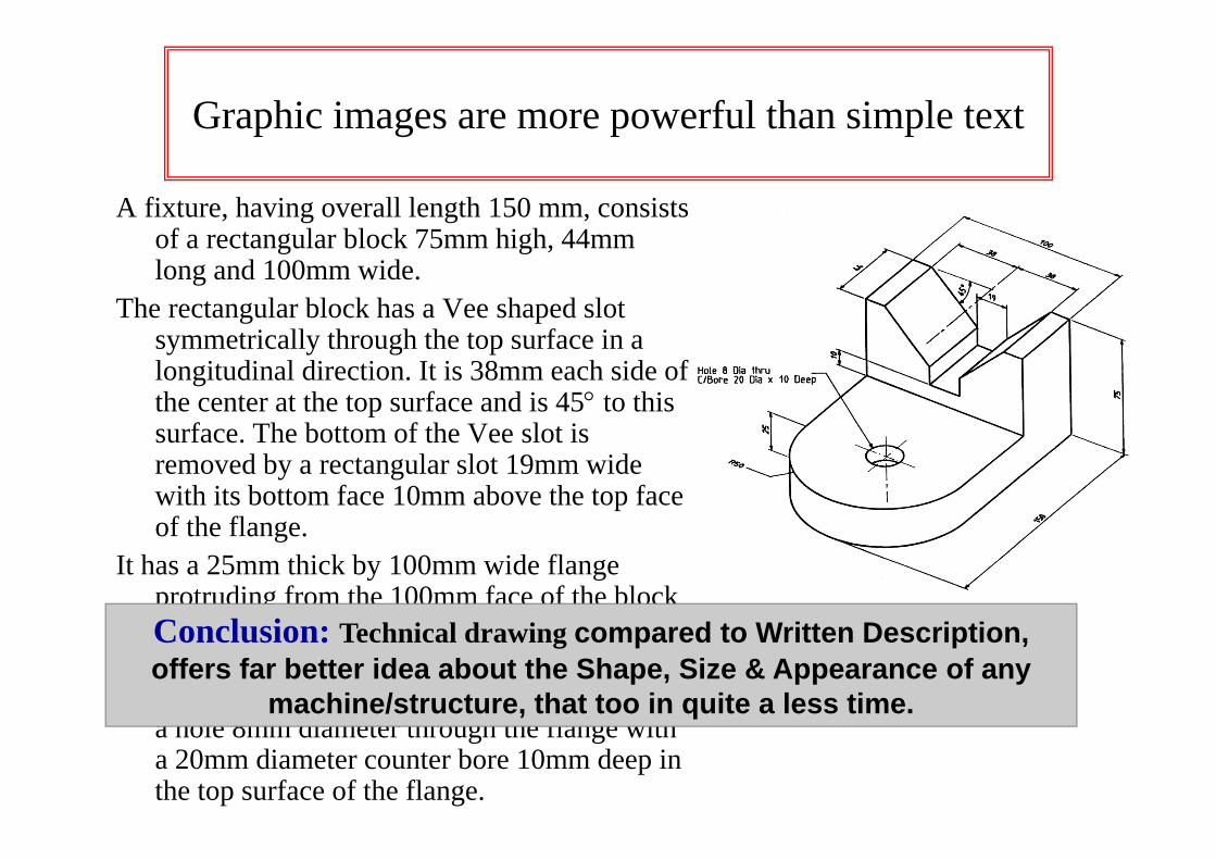
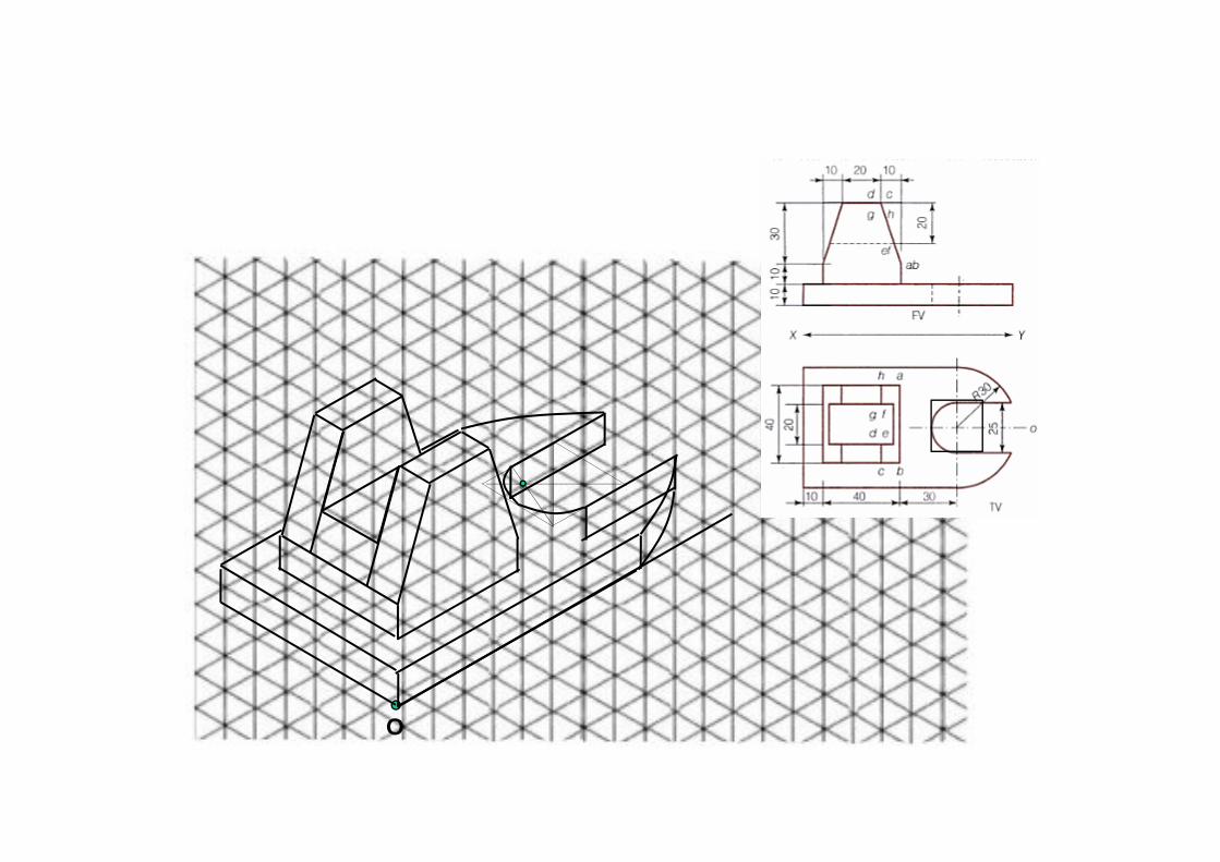
A fixture, having overall length 150 mm, consists of a rectangular block 75mm high, 44mm long and 100mm wide.
The rectangular block has a Vee shaped slot symmetrically through the top surface in a longitudinal direction. It is 38mm each side of the center at the top surface and is 45° to this surface. The bottom of the Vee slot is removed by a rectangular slot 19mm wide with its bottom face 10mm above the top face of the flange.
It has a 25mm thick by 100mm wide flange protruding from the 100mm face of the block with the lower surfaces aligned.
The free end of the flange is rounded with a 50mm radius and at the center of that radius is a hole 8mm diameter through the flange with a 20mm diameter counter bore 10mm deep in the top surface of the flange.
Conclusion: Technical drawing compared to Written Description,offers far better idea about the Shape, Size & Appearance of any
machine/structure, that too in quite a less time.
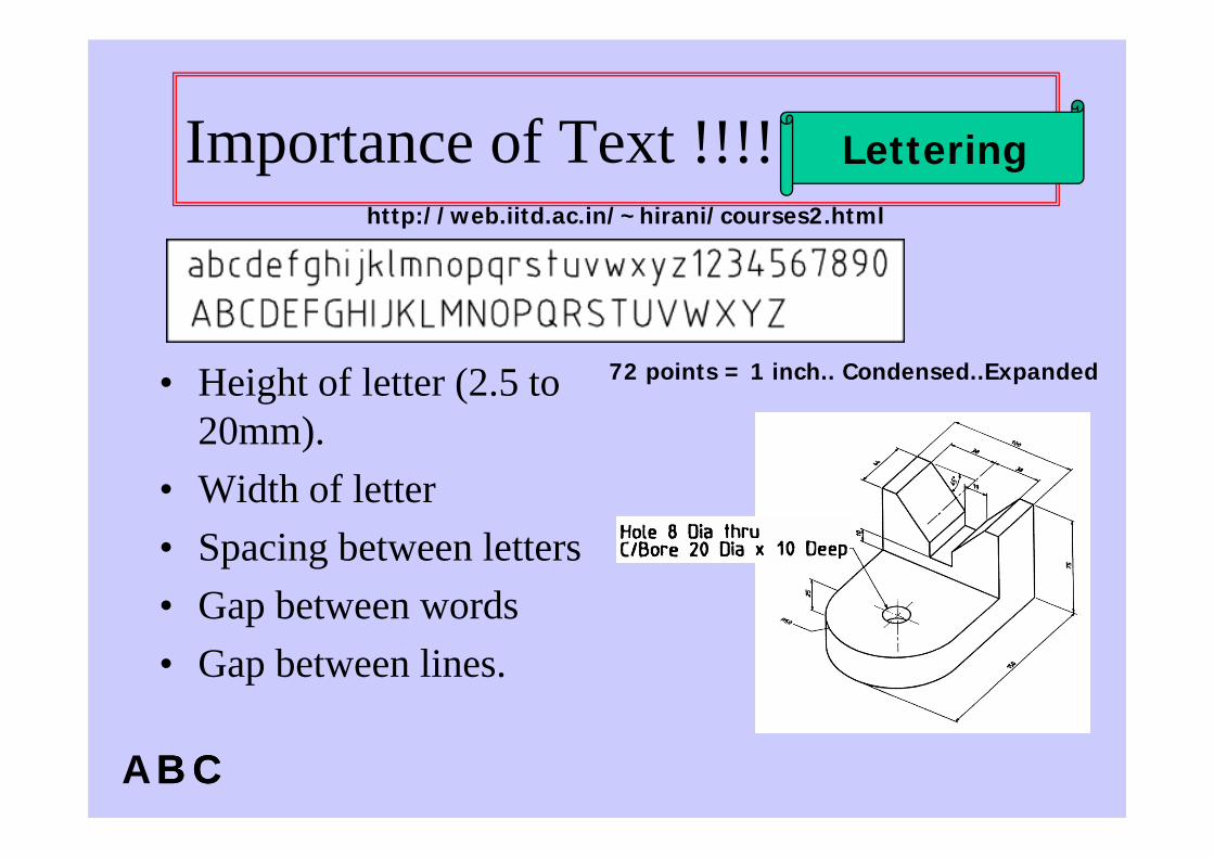
Importance of Text !!!!
• Height of letter (2.5 to 20mm).
• Width of letter • Spacing between letters• Gap between words• Gap between lines.
Lettering
A B CB C
72 points = 1 inch.. Condensed..Expanded
http://web.iitd.ac.in/~hirani/courses2.html
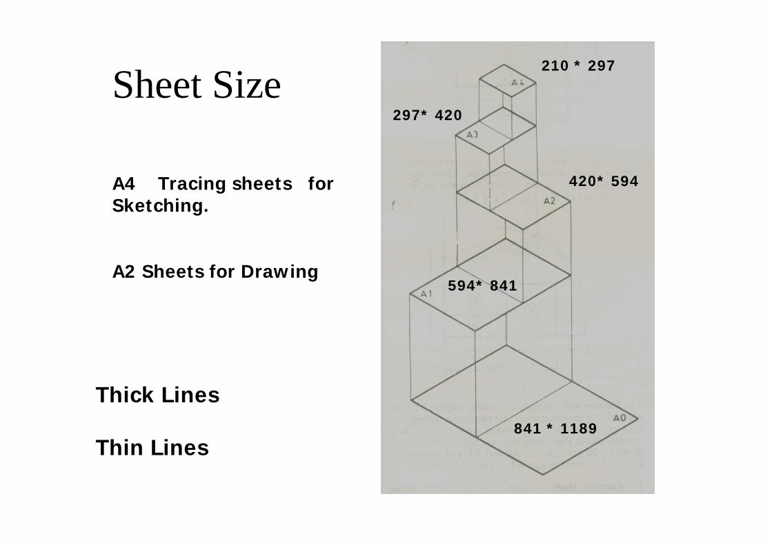
Sheet Size
841 * 1189
594* 841
420* 594
297* 420
210 * 297
A4 Tracing sheets for Sketching.
A2 Sheets for Drawing
Thick Lines
Thin Lines
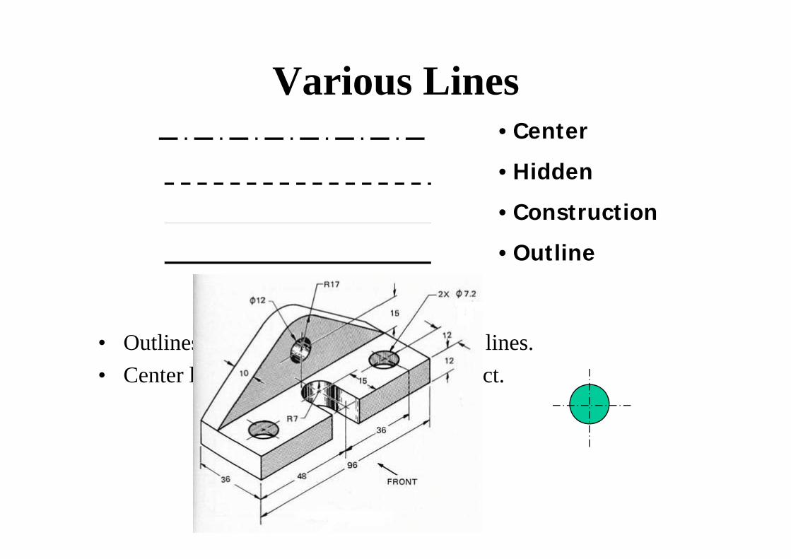
Various Lines
• Outlines are made thicker than all other lines.• Center line represents the center of object.
• Center
• Hidden
• Construction
• Outline
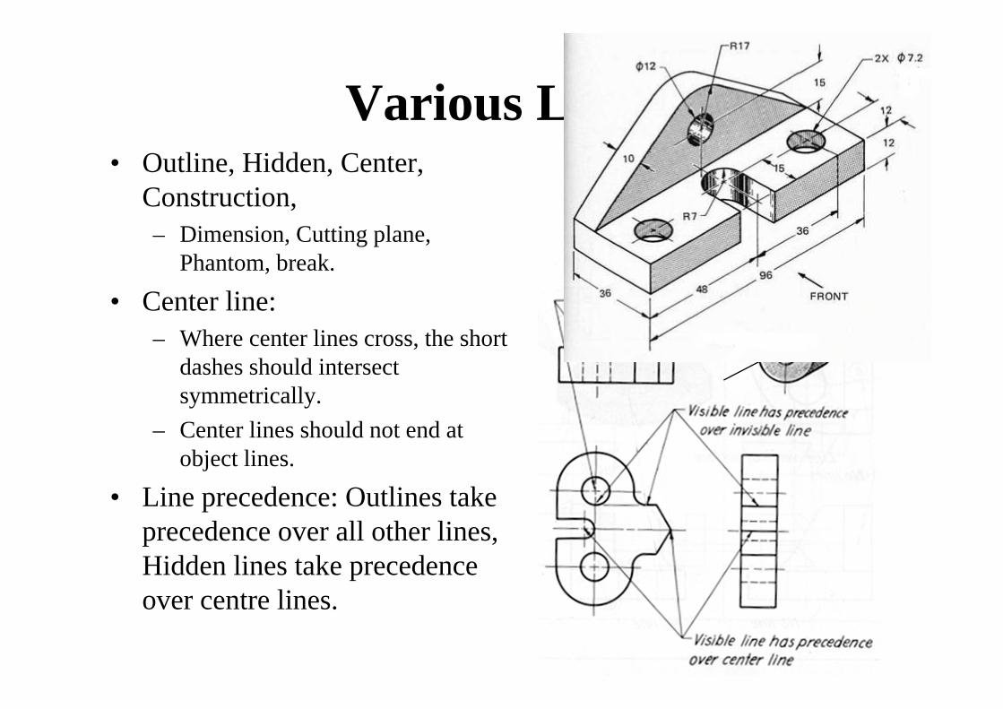
Various Lines• Outline, Hidden, Center,
Construction, – Dimension, Cutting plane,
Phantom, break.
• Center line: – Where center lines cross, the short
dashes should intersect symmetrically.
– Center lines should not end at object lines.
• Line precedence: Outlines take precedence over all other lines, Hidden lines take precedence over centre lines.
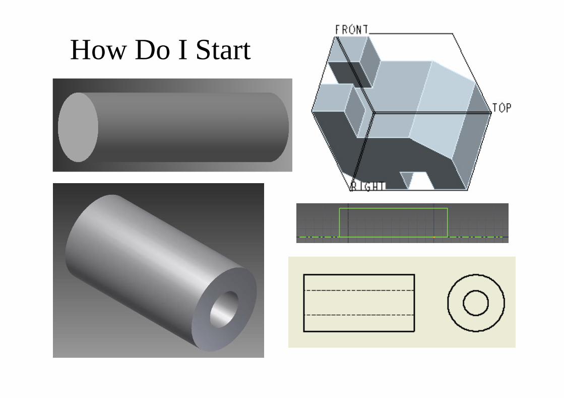
How Do I Start• Learn Pro-E.• Think few simple shapes.
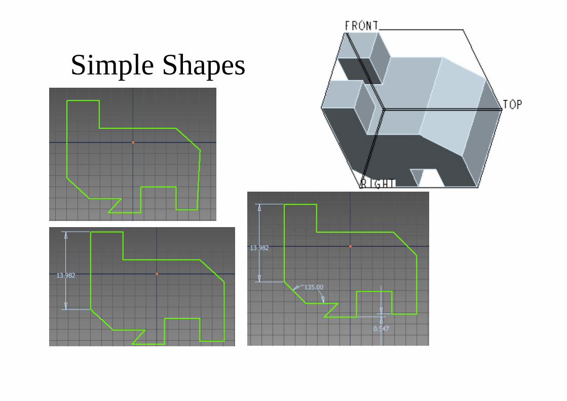
Simple Shapes
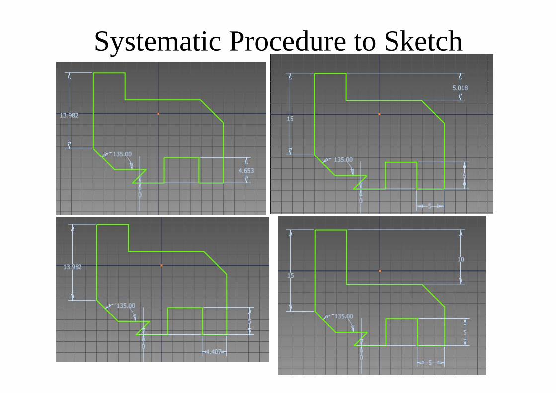
Systematic Procedure to Sketch
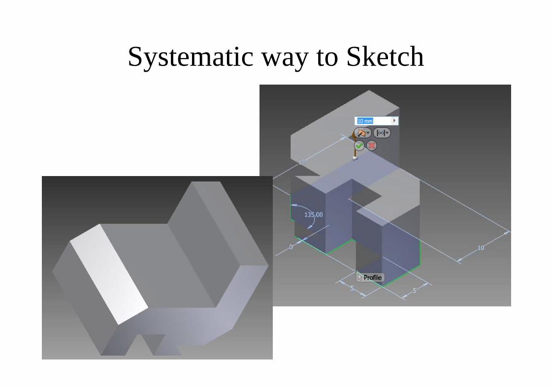
Systematic way to Sketch• Dimension smallest
to largest length.
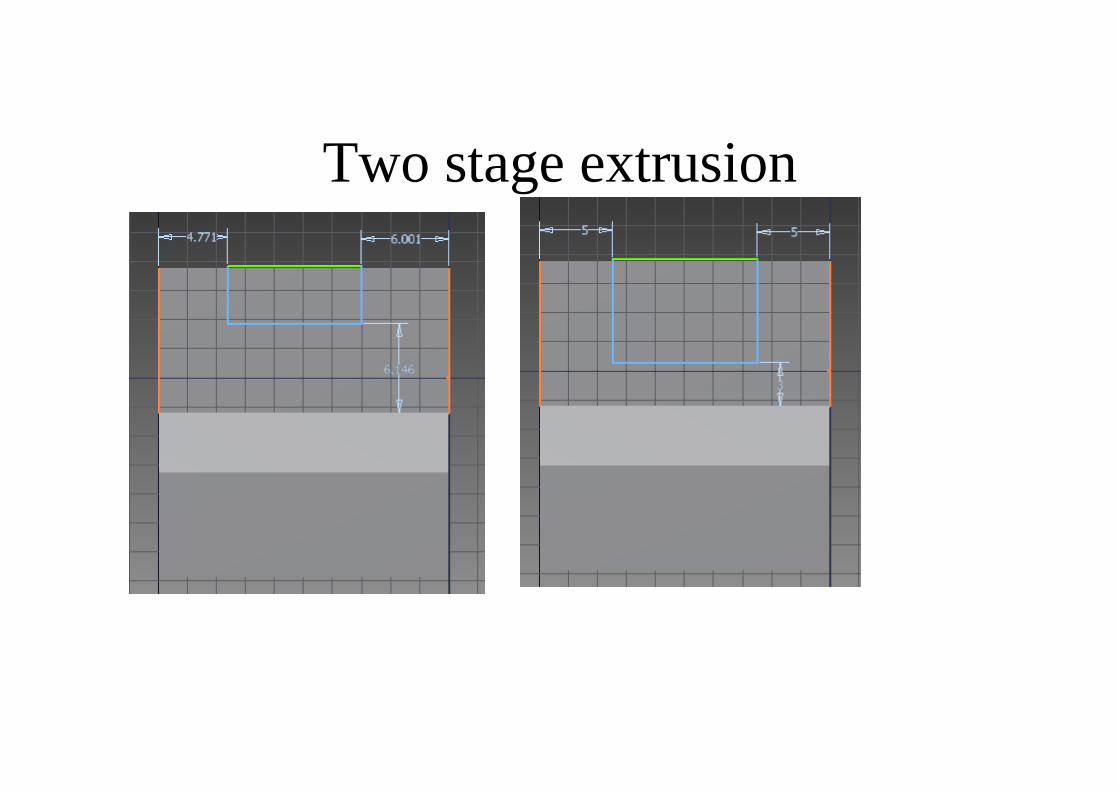
Two stage extrusion
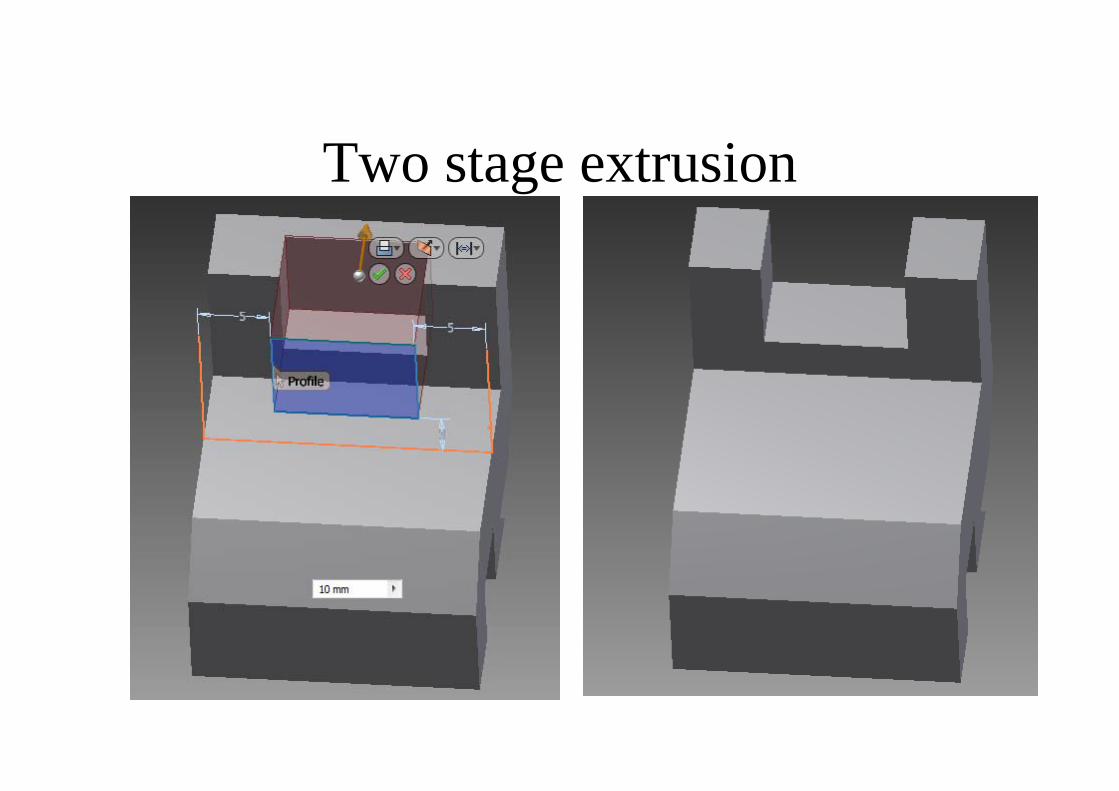
Two stage extrusion
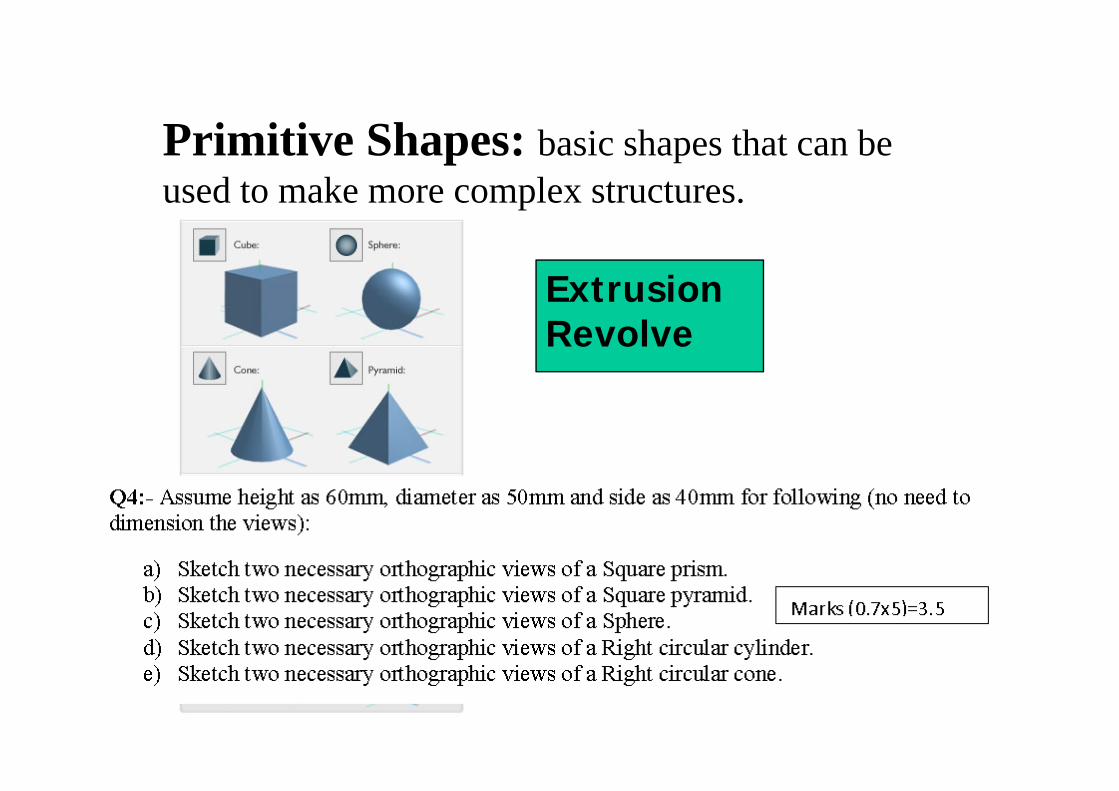
Primitive Shapes: basic shapes that can be used to make more complex structures.
Prism
Extrusion Revolve
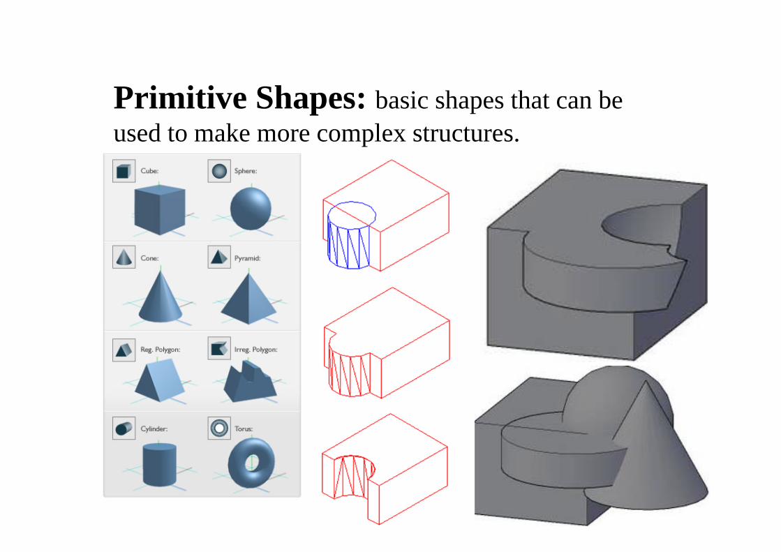
Primitive Shapes: basic shapes that can be used to make more complex structures.
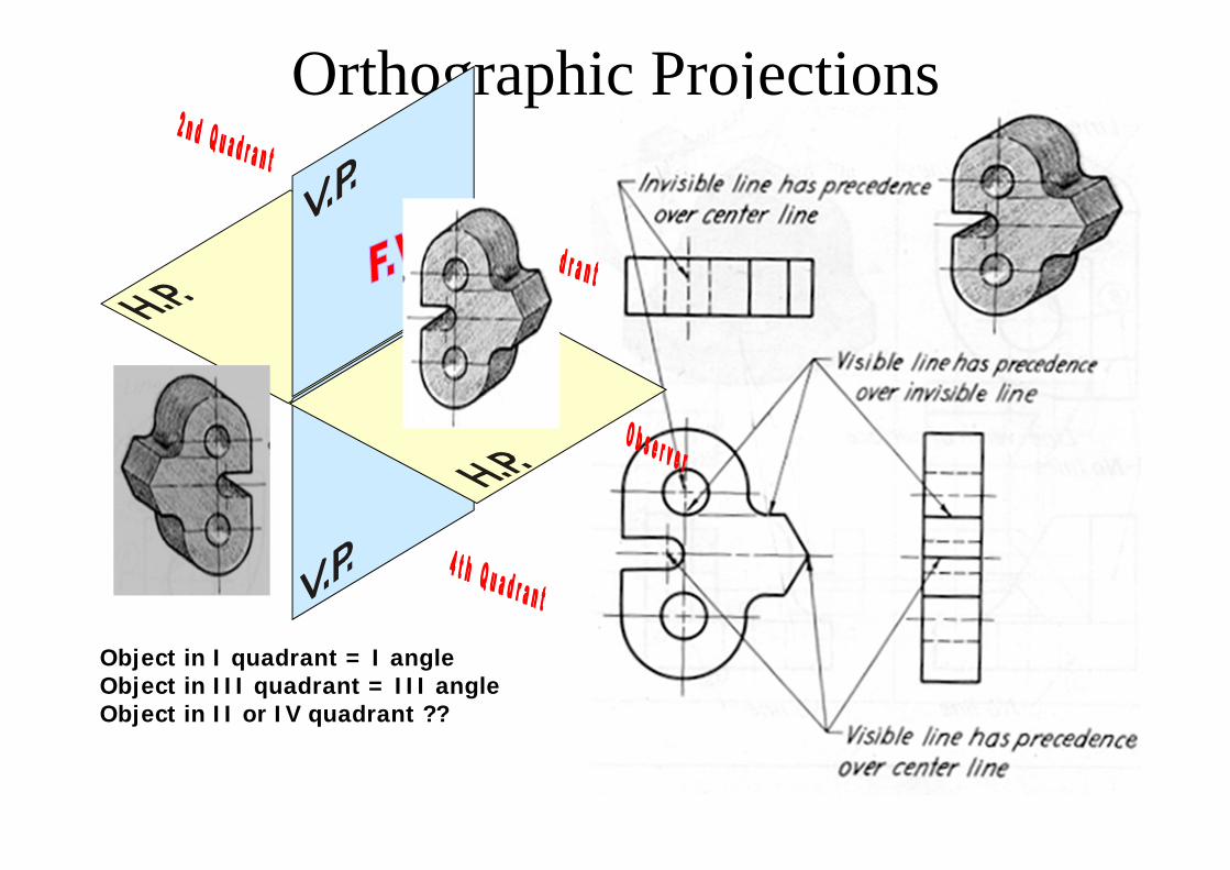
Orthographic Projections
X
Y
Object in I quadrant = I angleObject in III quadrant = III angleObject in II or IV quadrant ??
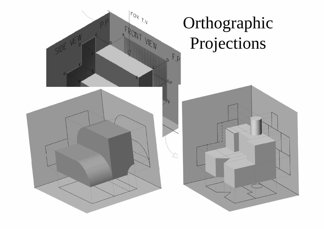
Orthographic Projections
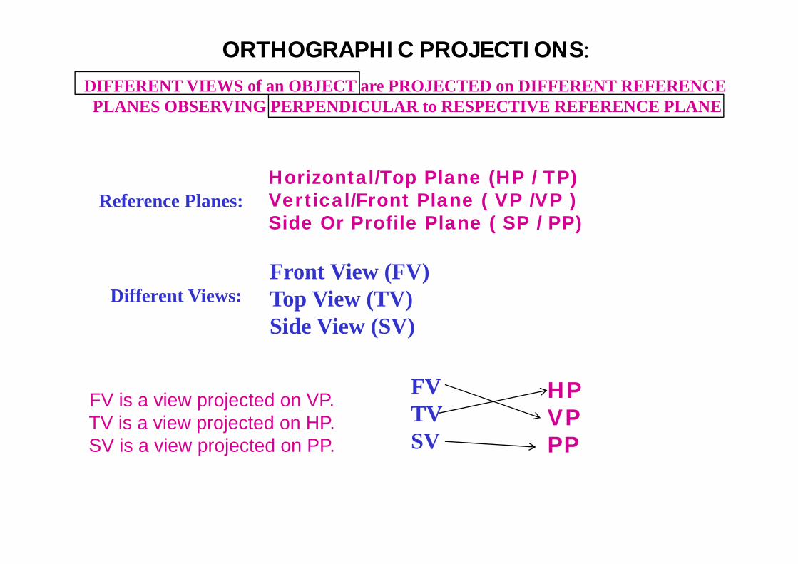
ORTHOGRAPHIC PROJECTIONS:
Horizontal/Top Plane (HP / TP) Vertical/Front Plane ( VP /VP ) Side Or Profile Plane ( SP / PP)
Reference Planes:
FV is a view projected on VP.TV is a view projected on HP.SV is a view projected on PP.
DIFFERENT VIEWS of an OBJECT are PROJECTED on DIFFERENT REFERENCE PLANES OBSERVING PERPENDICULAR to RESPECTIVE REFERENCE PLANE
Front View (FV)Top View (TV)Side View (SV)
Different Views:
FVTVSV
HP VP PP
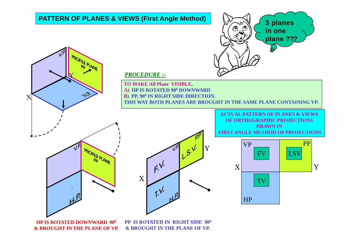
HP IS ROTATED DOWNWARD 900
& BROUGHT IN THE PLANE OF VP.PP IS ROTATED IN RIGHT SIDE 900
& BROUGHT IN THE PLANE OF VP.
X
Y
X Y
VP
HP
PPFV
ACTUAL PATTERN OF PLANES & VIEWS OF ORTHOGRAPHIC PROJECTIONS
DRAWN IN FIRST ANGLE METHOD OF PROJECTIONS
LSV
TV
PROCEDURE :-TO MAKE All Plane VISIBLE, A) HP IS ROTATED 900 DOWNWARD B) PP, 900 IN RIGHT SIDE DIRECTION.THIS WAY BOTH PLANES ARE BROUGHT IN THE SAME PLANE CONTAINING VP.
PATTERN OF PLANES & VIEWS (First Angle Method) 3 planes in one plane ???
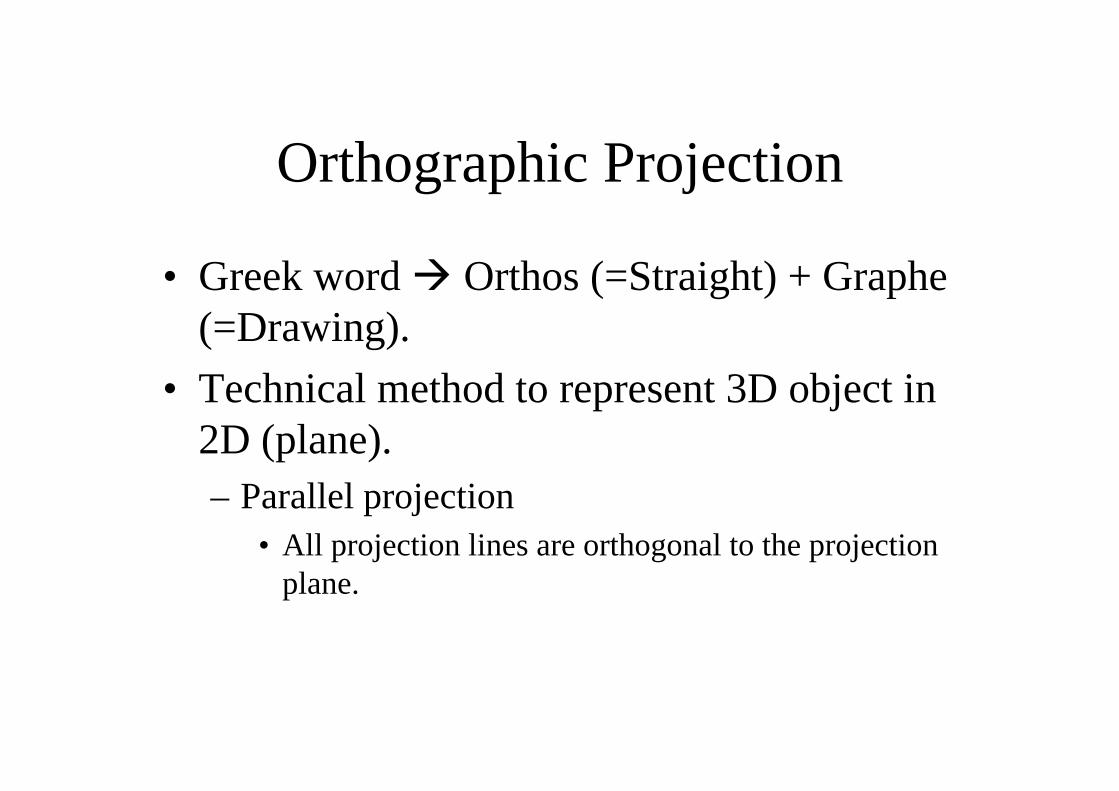
Orthographic Projection
• Greek word Orthos (=Straight) + Graphe(=Drawing).
• Technical method to represent 3D object in 2D (plane).– Parallel projection
• All projection lines are orthogonal to the projection plane.
x y
FRONT VIEW
TOP VIEW
L.H.SIDE VIEW
FOR T.V.
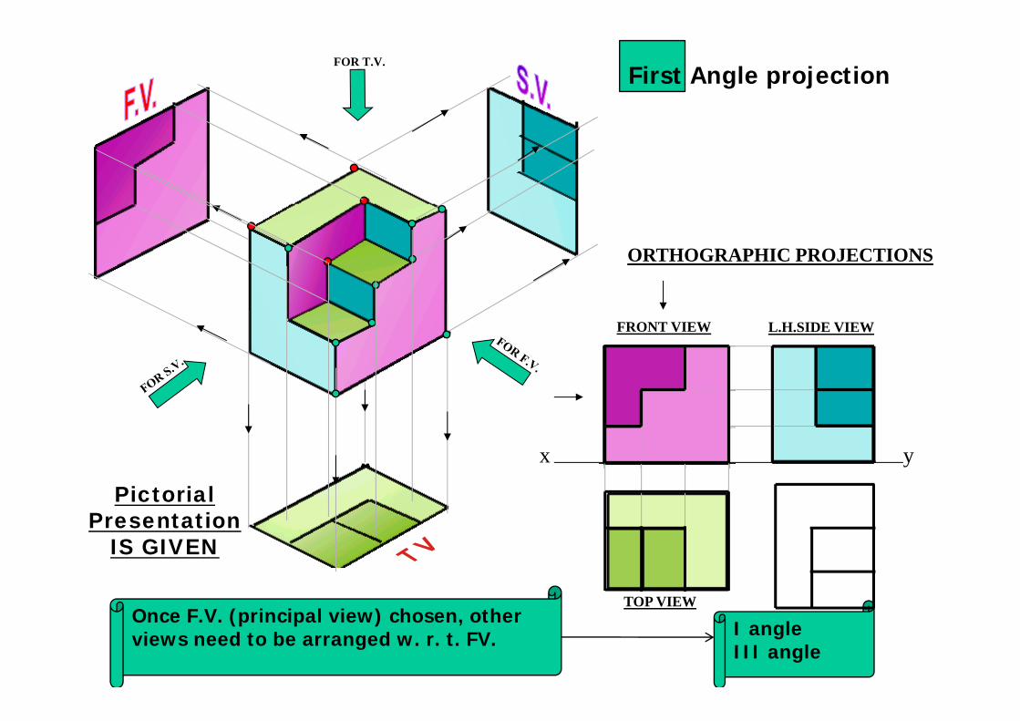
Pictorial Presentation
IS GIVEN
ORTHOGRAPHIC PROJECTIONS
First Angle projection
Once F.V. (principal view) chosen, other views need to be arranged w. r. t. FV. I angle
III angle
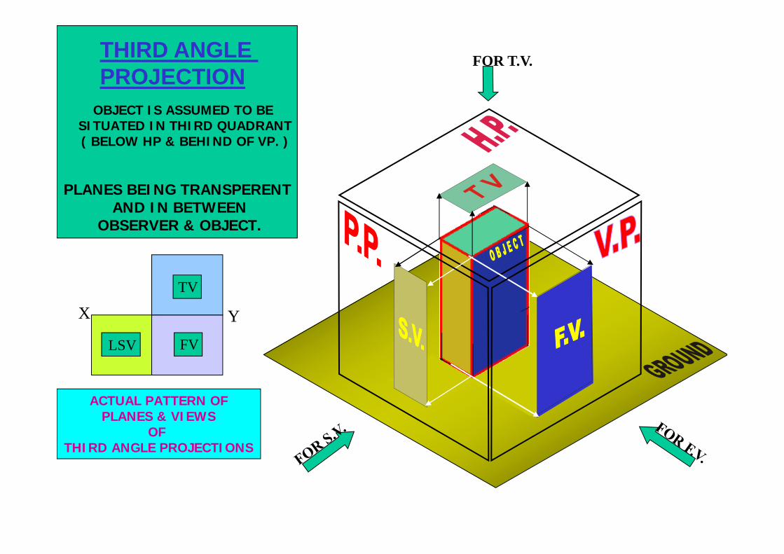
FOR T.V.
OBJECT IS ASSUMED TO BE SITUATED IN THIRD QUADRANT( BELOW HP & BEHIND OF VP. )
PLANES BEING TRANSPERENT AND IN BETWEEN
OBSERVER & OBJECT.
ACTUAL PATTERN OFPLANES & VIEWS
OF THIRD ANGLE PROJECTIONS
X Y
TV
THIRD ANGLE PROJECTION
LSV FV
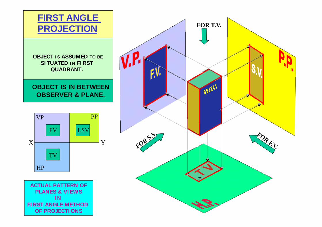
FOR T.V.FIRST ANGLE PROJECTION
OBJECT IS ASSUMED TO BESITUATED IN FIRST
QUADRANT.
OBJECT IS IN BETWEENOBSERVER & PLANE.
ACTUAL PATTERN OFPLANES & VIEWS
IN FIRST ANGLE METHOD
OF PROJECTIONS
X Y
VP
HP
PP
FV LSV
TV
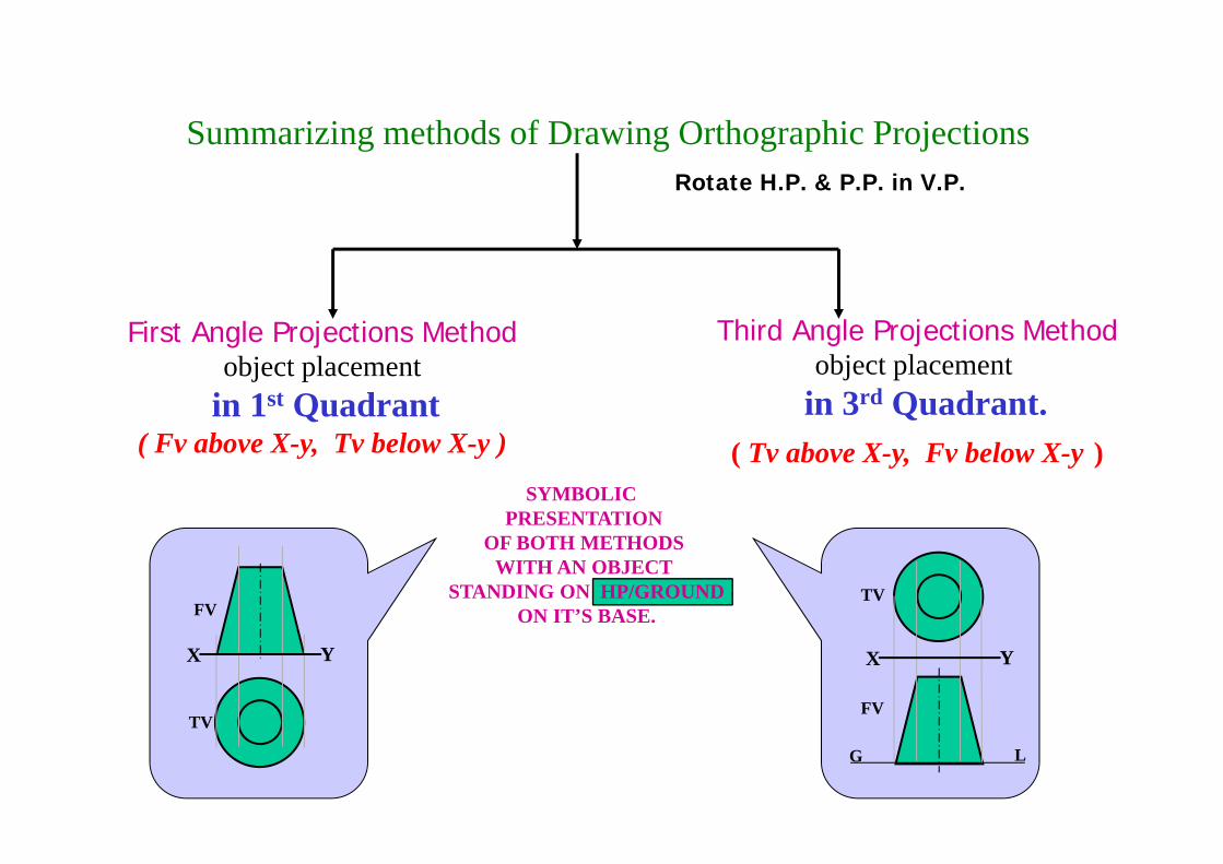
Summarizing methods of Drawing Orthographic Projections
First Angle Projections Methodobject placement
in 1st Quadrant( Fv above X-y, Tv below X-y )
Third Angle Projections Methodobject placement
in 3rd Quadrant. ( Tv above X-y, Fv below X-y )
FV
TV
X Y X Y
G L
TV
FV
SYMBOLIC PRESENTATION
OF BOTH METHODSWITH AN OBJECT
STANDING ON HP/GROUNDON IT’S BASE.
Rotate H.P. & P.P. in V.P.
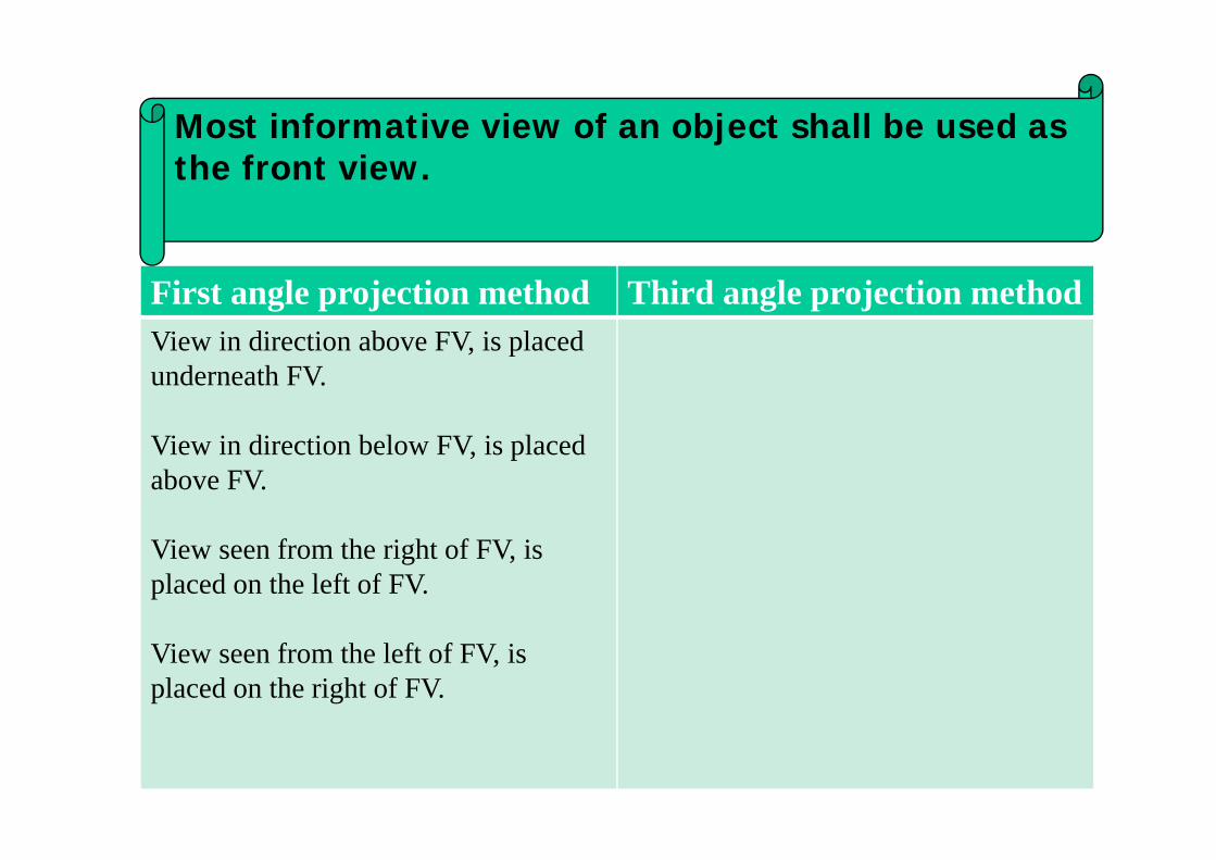
First angle projection method Third angle projection methodView in direction above FV, is placed underneath FV.
View in direction below FV, is placed above FV.
View seen from the right of FV, is placed on the left of FV.
View seen from the left of FV, is placed on the right of FV.
Most informative view of an object shall be used as the front view.
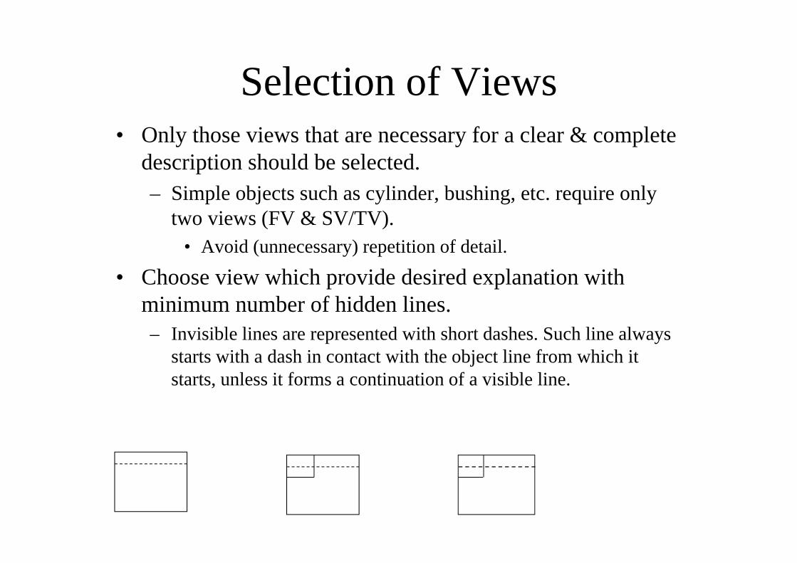
Selection of Views• Only those views that are necessary for a clear & complete
description should be selected.– Simple objects such as cylinder, bushing, etc. require only
two views (FV & SV/TV).• Avoid (unnecessary) repetition of detail.
• Choose view which provide desired explanation with minimum number of hidden lines.– Invisible lines are represented with short dashes. Such line always
starts with a dash in contact with the object line from which it starts, unless it forms a continuation of a visible line.
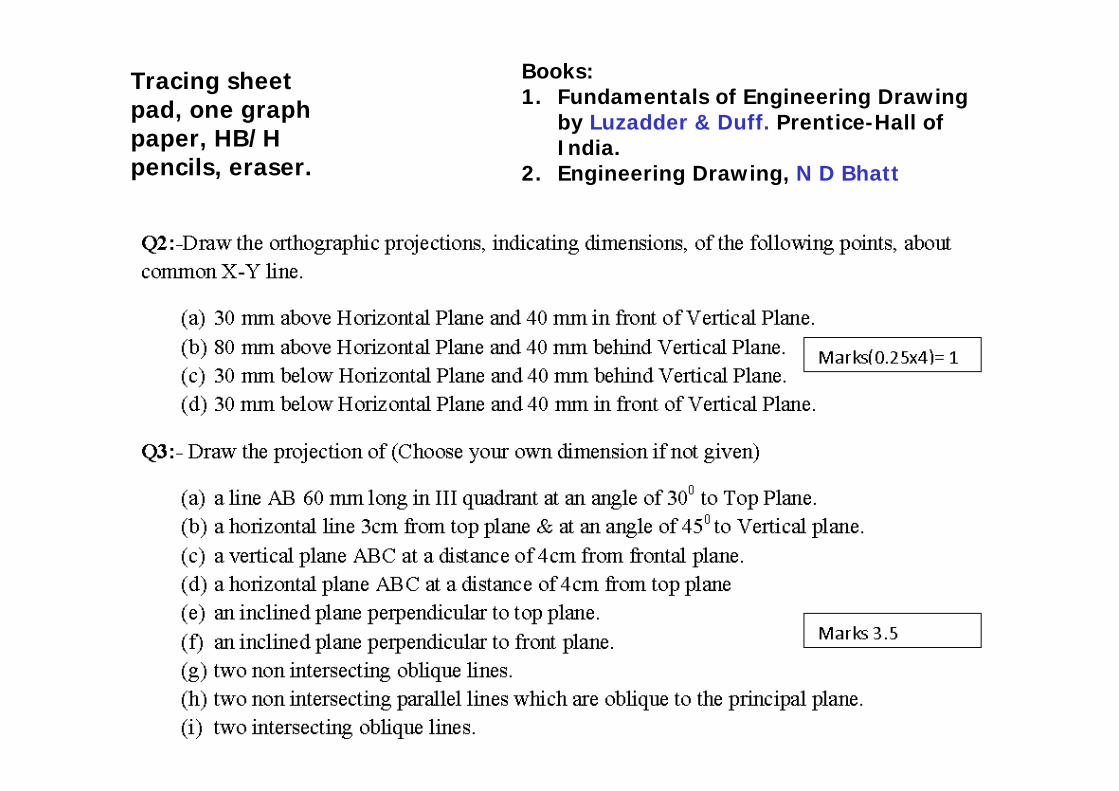
Tracing sheet pad, one graph paper, HB/H pencils, eraser.
Books:1. Fundamentals of Engineering Drawing
by Luzadder & Duff. Prentice-Hall of India.
2. Engineering Drawing, N D Bhatt
31
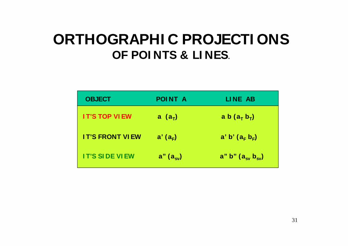
ORTHOGRAPHIC PROJECTIONSOF POINTS & LINES.
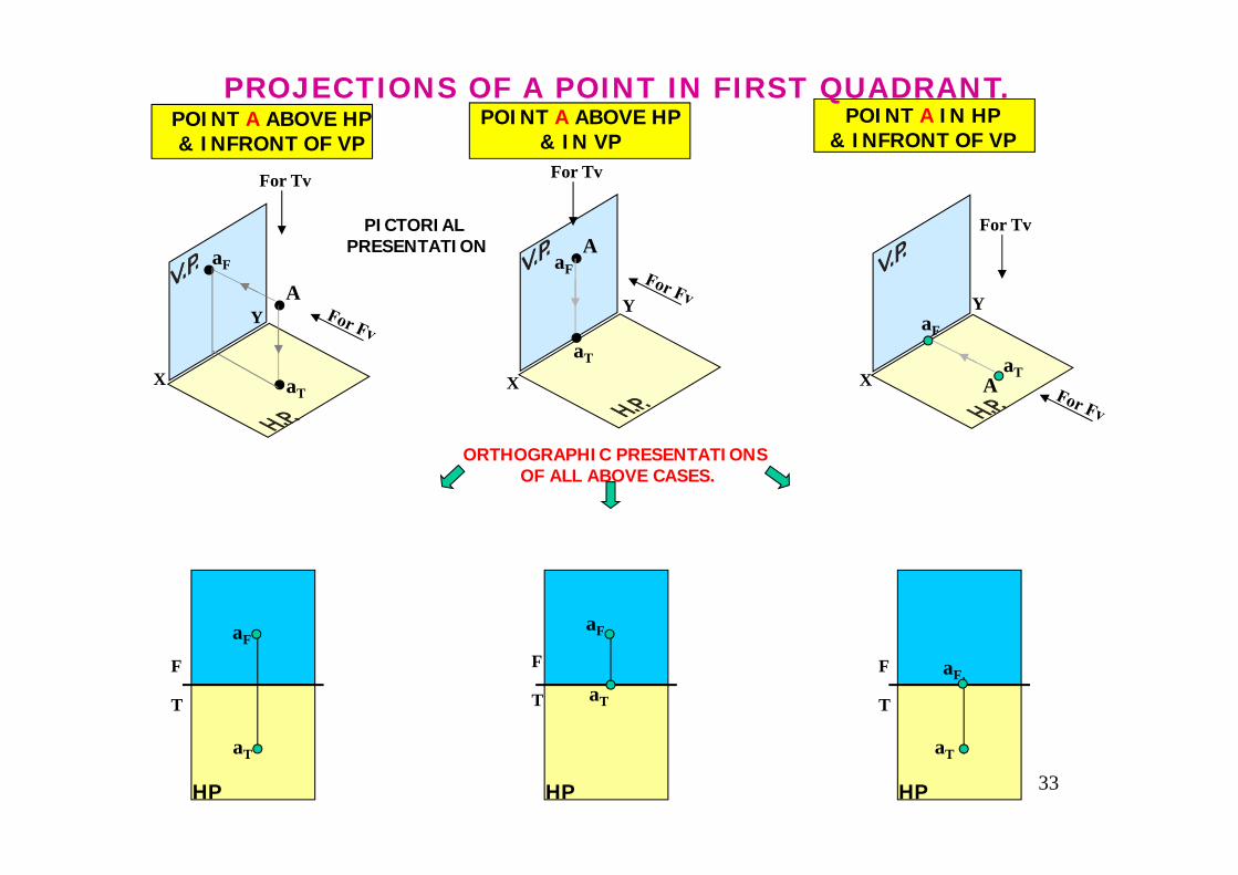
IT’S FRONT VIEW a’ (aF) a’ b’ (aF bF)
OBJECT POINT A LINE AB
IT’S TOP VIEW a (aT) a b (aT bT)
IT’S SIDE VIEW a” (asv) a” b” (asv bsv)
32
For Tv
A
a
a’
X
Y
For Tv
Aa
a’
X
Y
For Tv
A
a
a’
X
Y
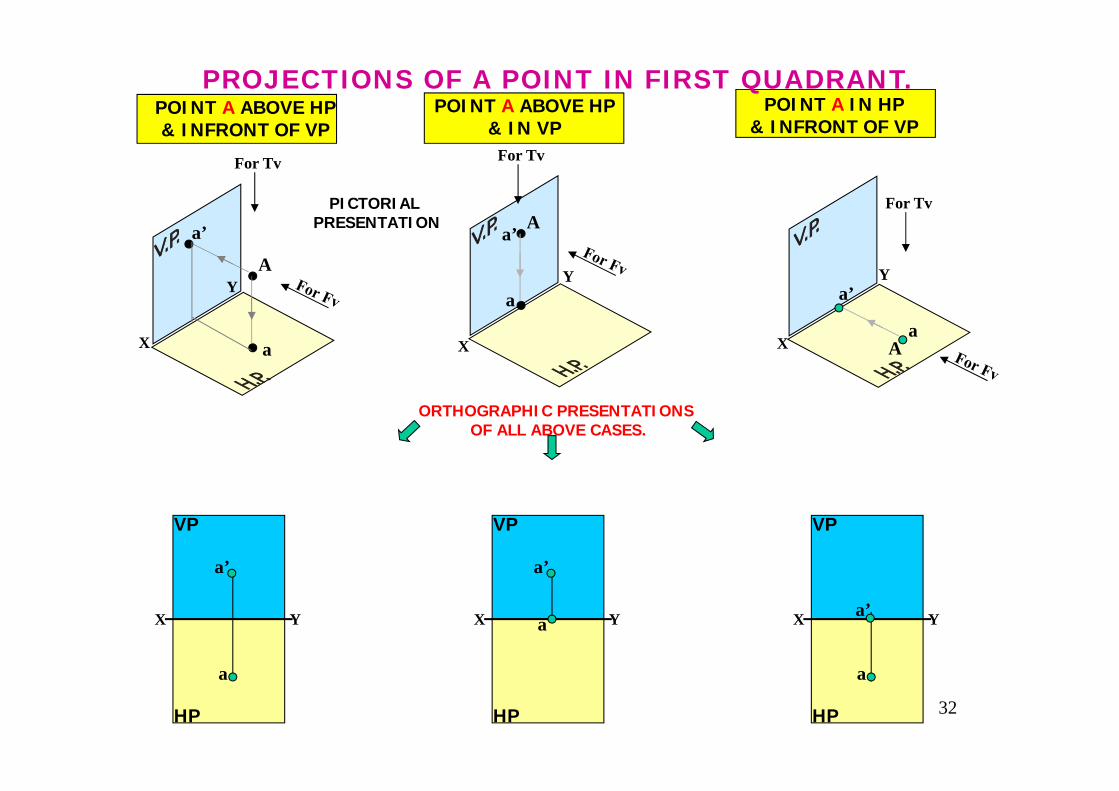
POINT A ABOVE HP& INFRONT OF VP
POINT A IN HP& INFRONT OF VP
POINT A ABOVE HP& IN VP
PROJECTIONS OF A POINT IN FIRST QUADRANT.
PICTORIAL PRESENTATION
ORTHOGRAPHIC PRESENTATIONS OF ALL ABOVE CASES.
X Y
a
a’
VP
HP
X Y
a’
VP
HP
a X Y
a
VP
HP
a’
33
For Tv
A
X
Y
For Tv
AX
Y
For Tv
A
aF
X
Y
POINT A ABOVE HP& INFRONT OF VP
POINT A IN HP& INFRONT OF VP
POINT A ABOVE HP& IN VP
PROJECTIONS OF A POINT IN FIRST QUADRANT.
PICTORIAL PRESENTATION
ORTHOGRAPHIC PRESENTATIONS OF ALL ABOVE CASES.
F
T
HP HP HP
aF
aF
aFaF
aF
aT
aT aT
aT
aT
aT
F
T
F
T
X
Y
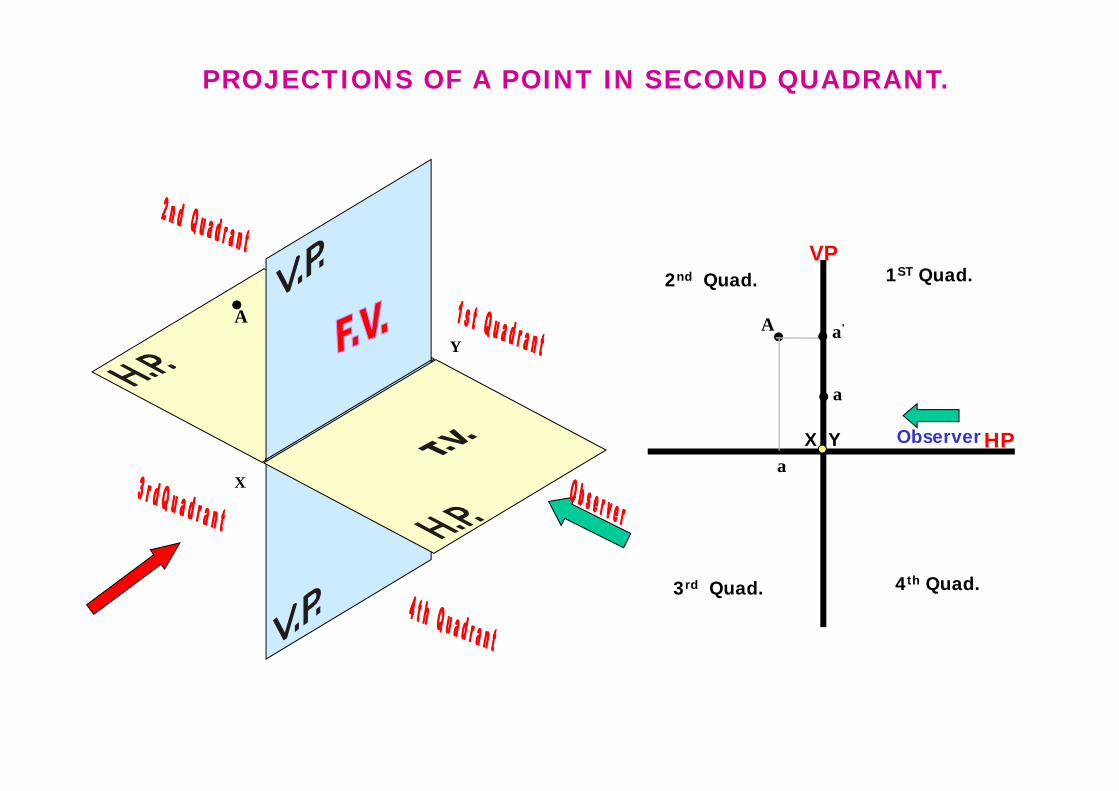
1ST Quad.2nd Quad.
3rd Quad. 4th Quad.
X Y
VP
HPObserver
PROJECTIONS OF A POINT IN SECOND QUADRANT.
A A a'
a
a
X
Y
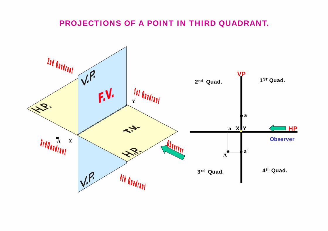
1ST Quad.2nd Quad.
3rd Quad. 4th Quad.
X Y
VP
HP
Observer
PROJECTIONS OF A POINT IN THIRD QUADRANT.
A
Aa'
a
a
36
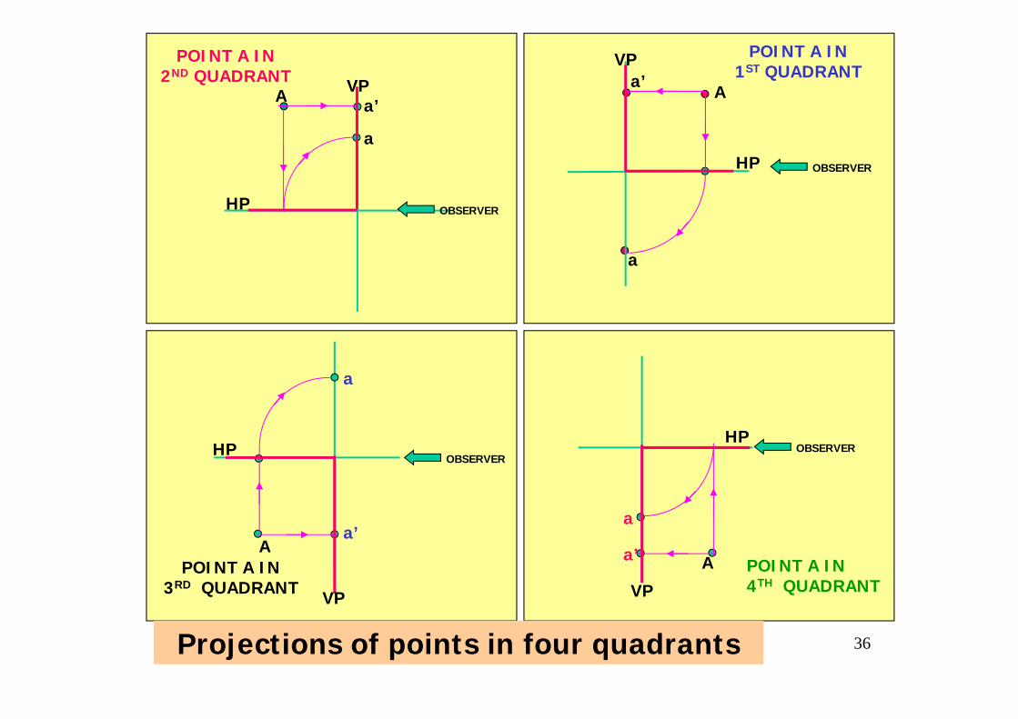
HP
VPa’
a
A
POINT A IN1ST QUADRANT
OBSERVER
VP
HP
POINT A IN2ND QUADRANT
OBSERVER
a’
a
A
OBSERVER
a
a’
POINT A IN3RD QUADRANT
HP
VP
A
OBSERVER
a
a’POINT A IN4TH QUADRANT
HP
VP
A
Projections of points in four quadrants
37
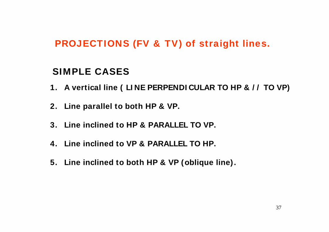
SIMPLE CASES1. A vertical line ( LINE PERPENDICULAR TO HP & // TO VP)
2. Line parallel to both HP & VP.
3. Line inclined to HP & PARALLEL TO VP.
4. Line inclined to VP & PARALLEL TO HP.
5. Line inclined to both HP & VP (oblique line).
PROJECTIONS (FV & TV) of straight lines.
38
X Y
H.P.
V.P. a’
b’
a b
Fv
Tv
X Y
H.P.
V.P.
a b
a’ b’Fv
Tv
X
Y
a b
a’
b’
B
A
TV
FV
For Tv
X
Y
b’
a’
b
a
A
B
For Tv
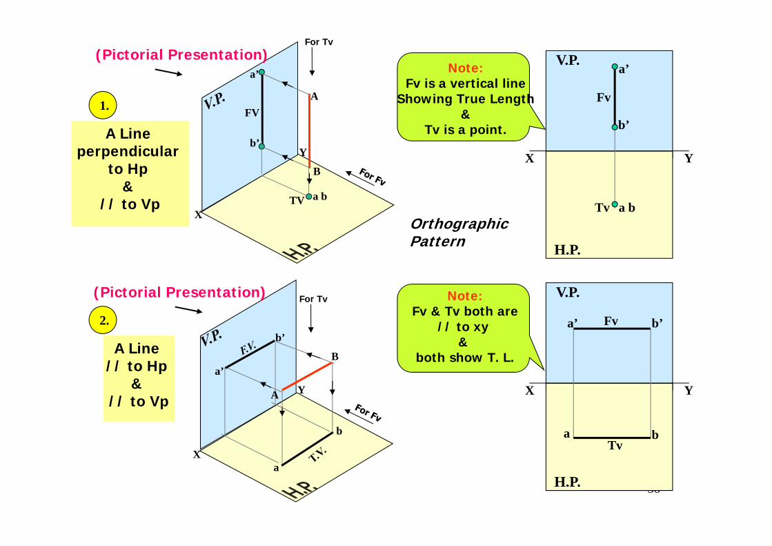
Note:Fv is a vertical line
Showing True Length&
Tv is a point.
Note:Fv & Tv both are
// to xy &
both show T. L.
1.
2.
A Line perpendicular
to Hp &
// to Vp
A Line // to Hp
& // to Vp
Orthographic Pattern
(Pictorial Presentation)
(Pictorial Presentation)
39
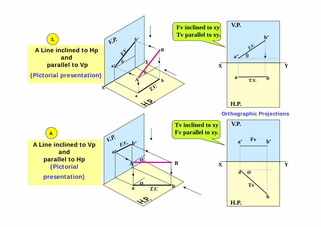
A Line inclined to Hp and
parallel to Vp
(Pictorial presentation)
X
Y
A
B
b’
a’
b
a
θ
θ
A Line inclined to Vpand
parallel to Hp(Pictorial
presentation)Ø
a b
a’b’
BAØ
X Y
H.P.
V.P.
T.V.a b
a’
b’
θ
X Y
H.P.
V.P.
Øa
b
a’ b’
Tv
Fv
Tv inclined to xyFv parallel to xy.
3.
4.
Fv inclined to xyTv parallel to xy.
Orthographic Projections
40
X
Ya’
b’
a b
B
A
α
β
For Tv
T.V.
X
Y
a’
b’
a b
α
β
T.V.
For Tv
B
A
X Y
α
β
H.P.
V.P.
a
b
FV
TV
a’
b’
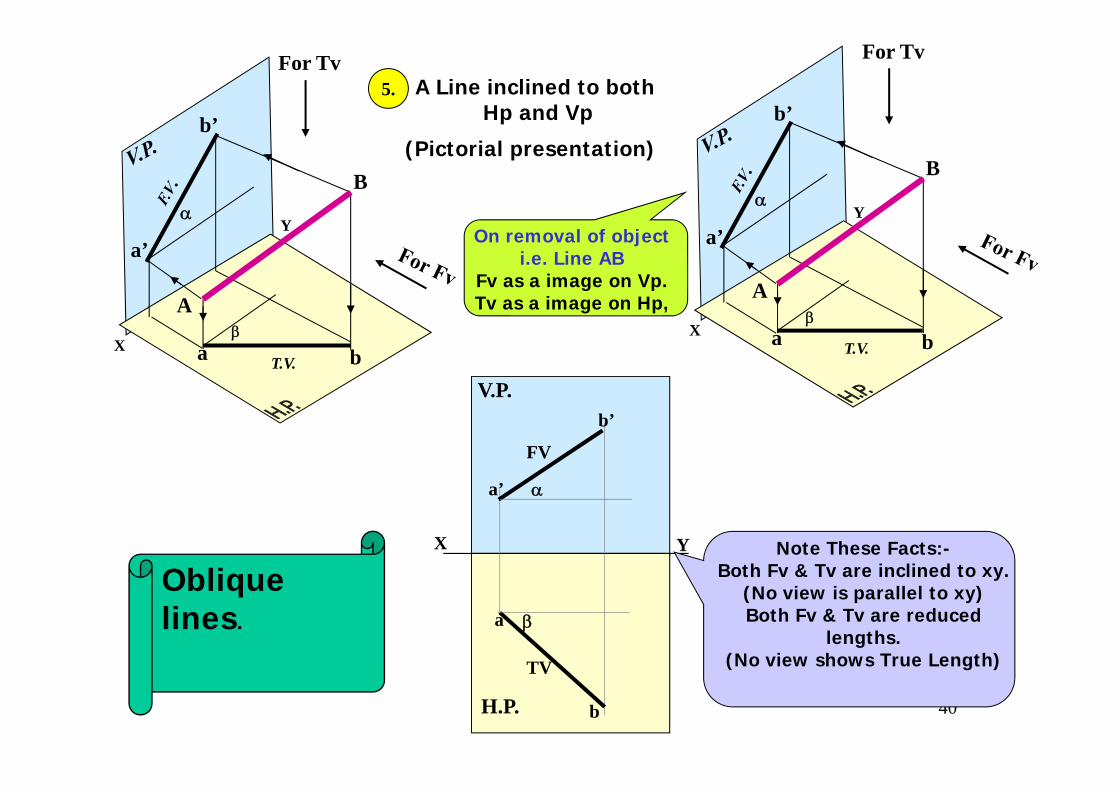
A Line inclined to bothHp and Vp
(Pictorial presentation)
5.
Note These Facts:-Both Fv & Tv are inclined to xy.
(No view is parallel to xy)Both Fv & Tv are reduced
lengths.(No view shows True Length)
On removal of objecti.e. Line AB
Fv as a image on Vp.Tv as a image on Hp,
Oblique lines.
HP
VPVPVP
a’ d’c’b’
HP
a
b c
d
a1’
d1’ c1’
b1’
HP
a1
b1 c1
d1
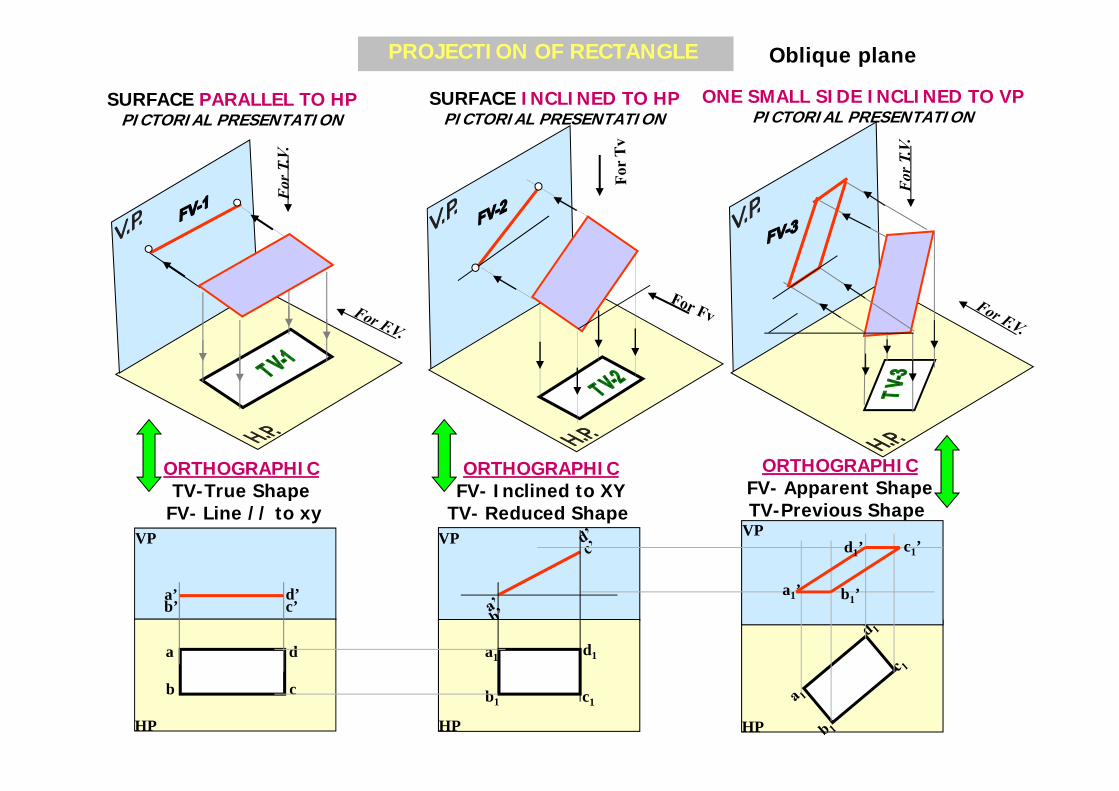
PROJECTION OF RECTANGLE
SURFACE PARALLEL TO HPPICTORIAL PRESENTATION
SURFACE INCLINED TO HPPICTORIAL PRESENTATION
ONE SMALL SIDE INCLINED TO VPPICTORIAL PRESENTATION
ORTHOGRAPHICTV-True Shape
FV- Line // to xy
ORTHOGRAPHICFV- Inclined to XY
TV- Reduced Shape
ORTHOGRAPHICFV- Apparent ShapeTV-Previous Shape
Oblique plane
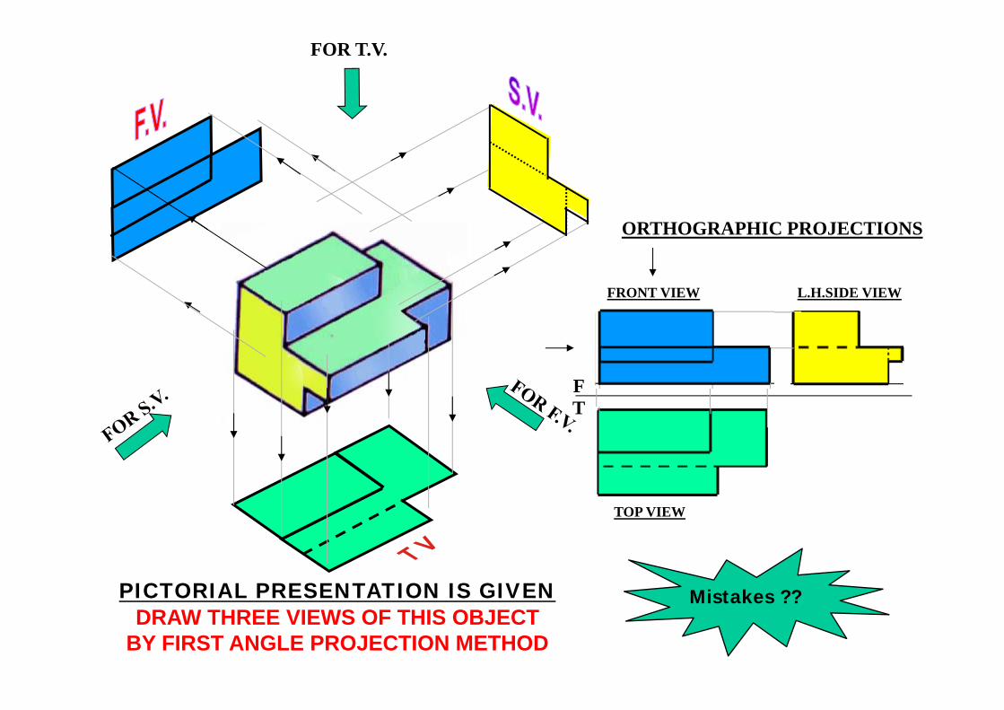
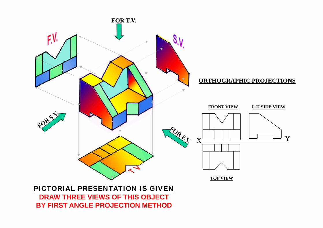
FOR T.V.
FT
FRONT VIEW
TOP VIEW
L.H.SIDE VIEW
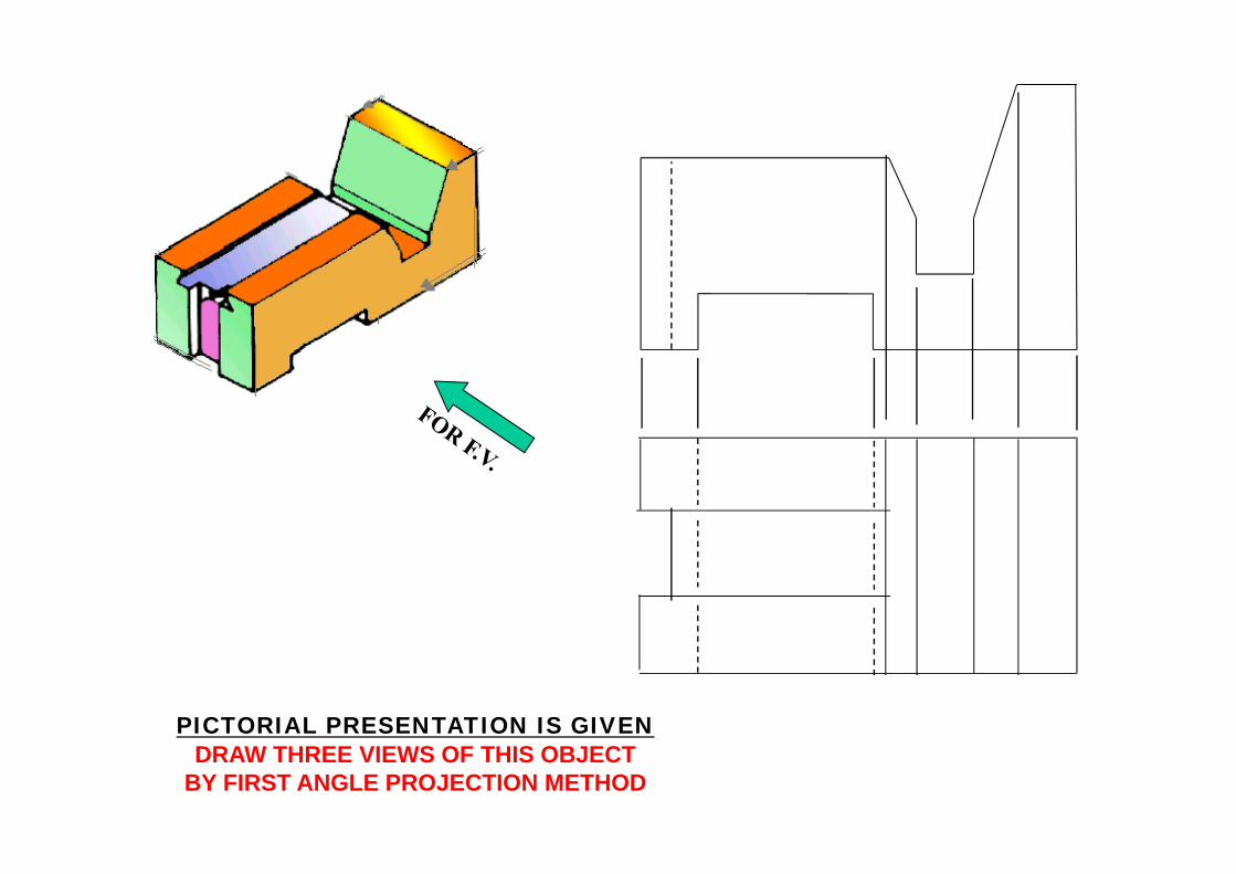
ORTHOGRAPHIC PROJECTIONS
PICTORIAL PRESENTATION IS GIVENDRAW THREE VIEWS OF THIS OBJECT
BY FIRST ANGLE PROJECTION METHOD
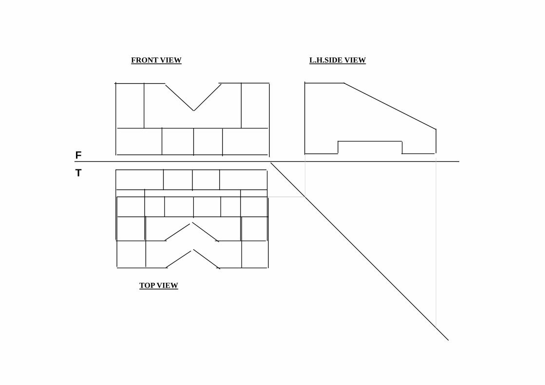
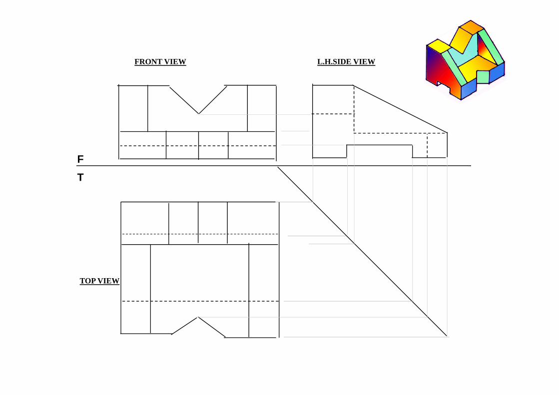
Mistakes ??
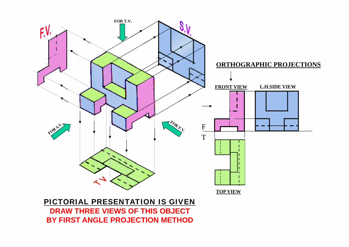
FOR T.V.
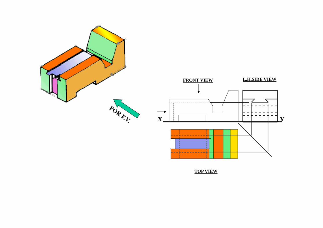
ORTHOGRAPHIC PROJECTIONS
FT
FRONT VIEW
TOP VIEW
L.H.SIDE VIEW
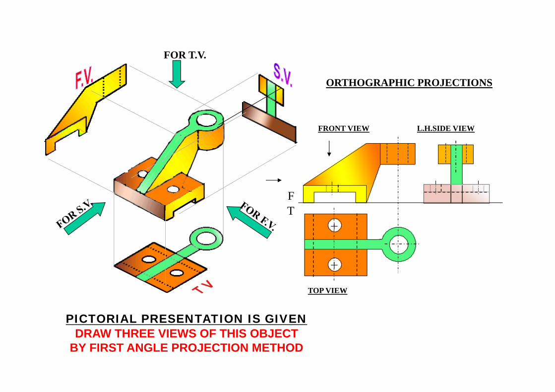
PICTORIAL PRESENTATION IS GIVENDRAW THREE VIEWS OF THIS OBJECT
BY FIRST ANGLE PROJECTION METHOD
FOR T.V.
ORTHOGRAPHIC PROJECTIONS
PICTORIAL PRESENTATION IS GIVENDRAW THREE VIEWS OF THIS OBJECT
BY FIRST ANGLE PROJECTION METHOD
FRONT VIEW
TOP VIEW
L.H.SIDE VIEW
X Y
FRONT VIEW
TOP VIEW
L.H.SIDE VIEW
F
T
FRONT VIEW
TOP VIEW
L.H.SIDE VIEW
F
T
FOR T.V.
ORTHOGRAPHIC PROJECTIONS
FRONT VIEW
TOP VIEW
L.H.SIDE VIEW
FT
PICTORIAL PRESENTATION IS GIVENDRAW THREE VIEWS OF THIS OBJECT
BY FIRST ANGLE PROJECTION METHOD
PICTORIAL PRESENTATION IS GIVENDRAW THREE VIEWS OF THIS OBJECT
BY FIRST ANGLE PROJECTION METHOD
FRONT VIEW
TOP VIEW
L.H.SIDE VIEW
X Y
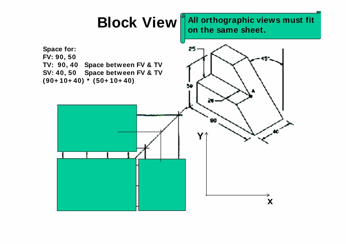
Space for:FV: 90, 50TV: 90, 40 Space between FV & TVSV: 40, 50 Space between FV & TV(90+10+40) * (50+10+40)
x
Y
Block View All orthographic views must fit on the same sheet.
Summarizing previous lectures
• Block view• Fold line• Projection Front, Top and side views
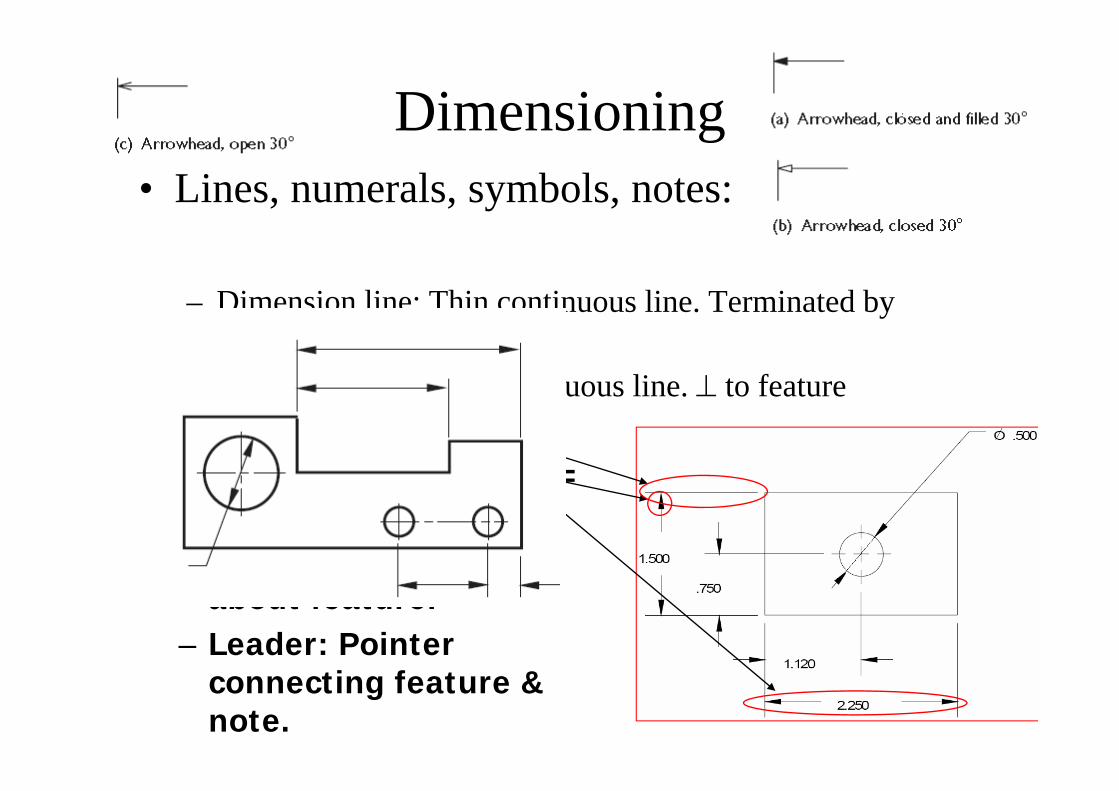
Dimensioning• Lines, numerals, symbols, notes:
– Dimension line: Thin continuous line. Terminated by arrowheads.
– Extension line: Thin continuous line. ⊥ to feature– Arrowhead:
Closed/Open. Length = 3* Width.
– Note: Specific info about feature.
– Leader: Pointer connecting feature & note.
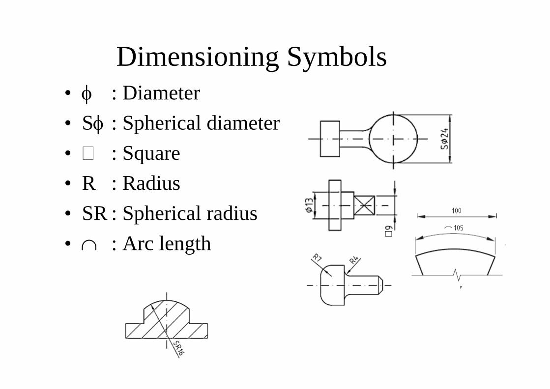
Dimensioning Symbols• φ : Diameter• Sφ : Spherical diameter• : Square• R : Radius• SR : Spherical radius• ∩ : Arc length

Dimensioning of Chamfers & Multi-features
Pitch circle diameter
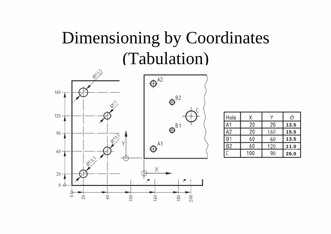
Dimensioning by Coordinates (Tabulation)
26.0
13.515.513.511.0
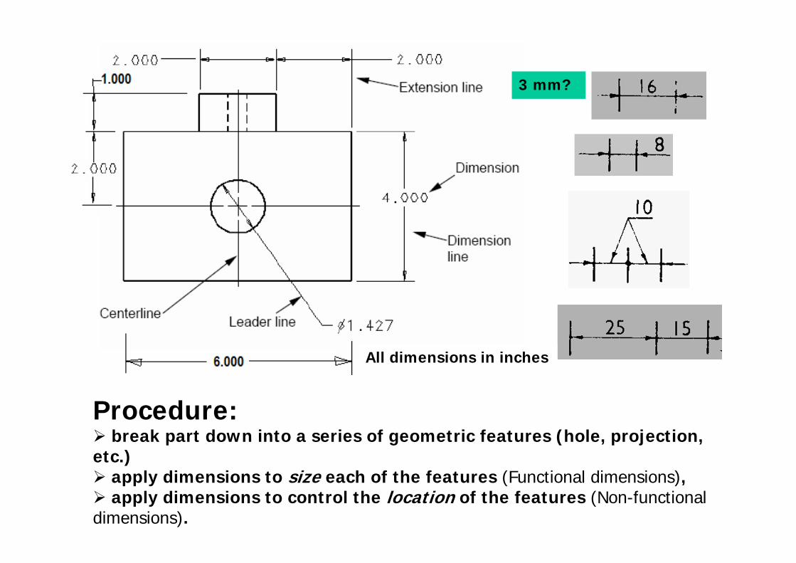
Procedure:break part down into a series of geometric features (hole, projection,
etc.)apply dimensions to size each of the features (Functional dimensions),apply dimensions to control the location of the features (Non-functional
dimensions).
3 mm?
All dimensions in inches
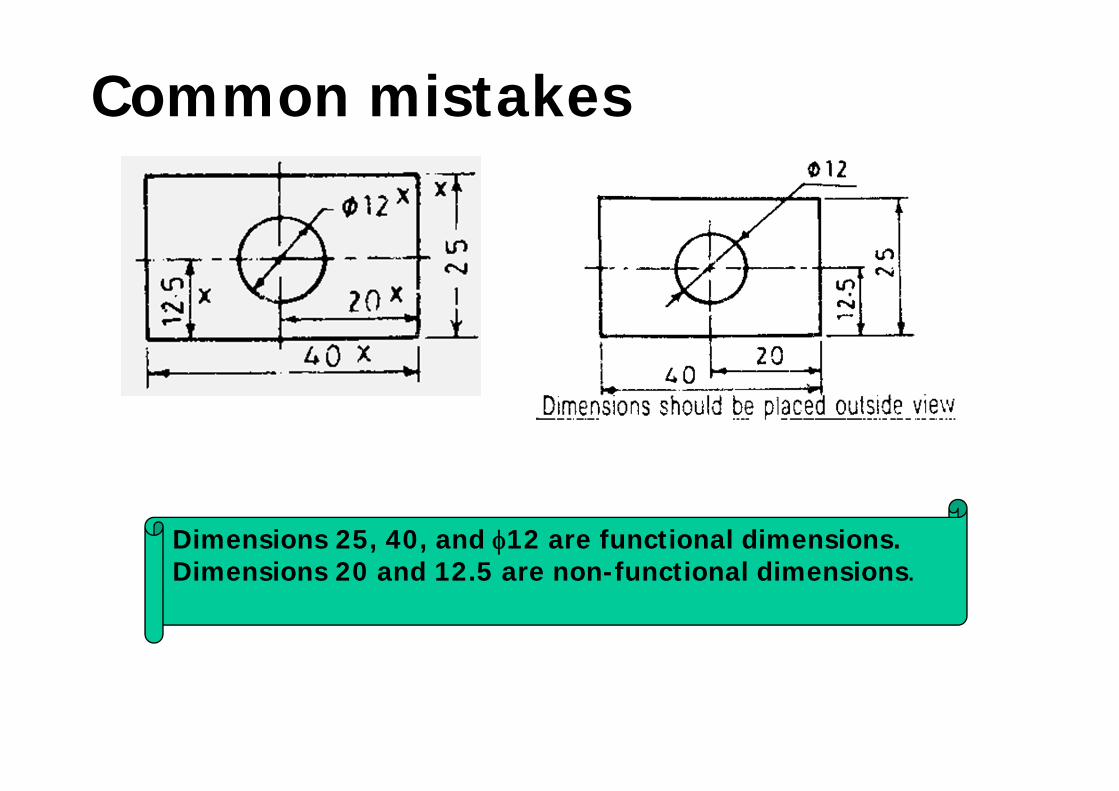
Common mistakes
Dimensions 25, 40, and φ12 are functional dimensions. Dimensions 20 and 12.5 are non-functional dimensions.
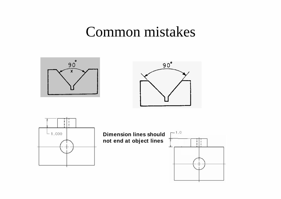
Common mistakes
Dimension lines should not end at object lines
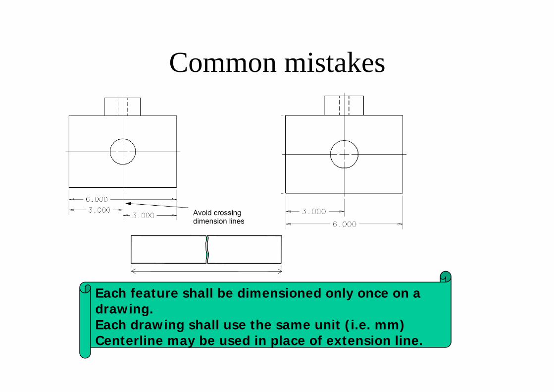
Common mistakes
Each feature shall be dimensioned only once on a drawing.Each drawing shall use the same unit (i.e. mm)Centerline may be used in place of extension line.
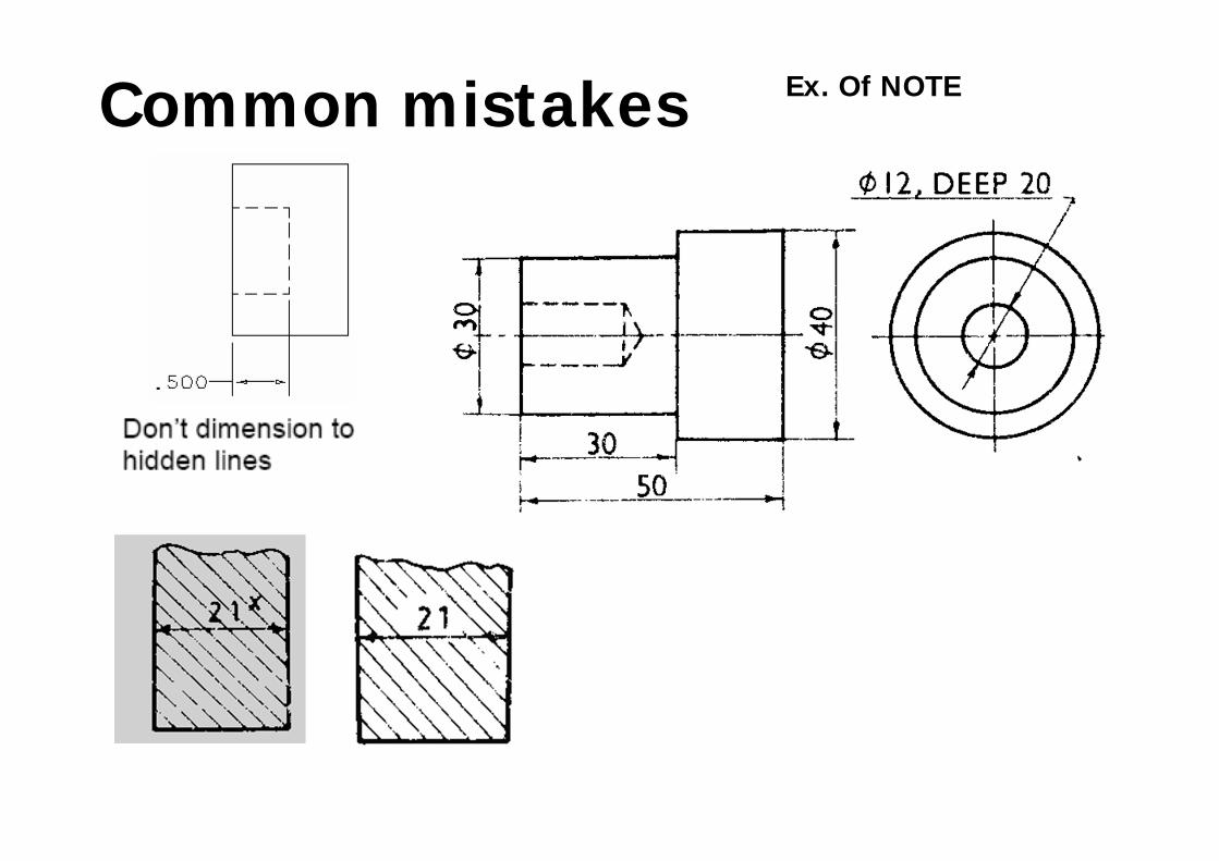
Common mistakes Ex. Of NOTE
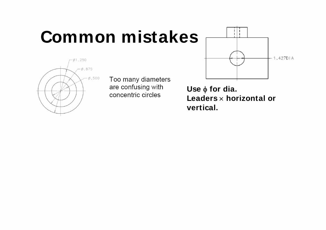
Common mistakes
Use φ for dia. Leaders × horizontal or vertical.
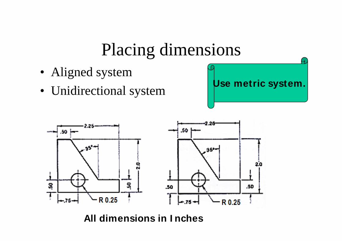
Placing dimensions• Aligned system• Unidirectional system Use metric system.
All dimensions in Inches
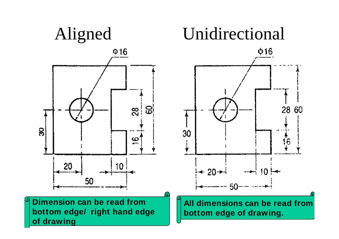
Aligned Unidirectional
All dimensions can be read frombottom edge of drawing.
Dimension can be read from bottom edge/ right hand edge of drawing
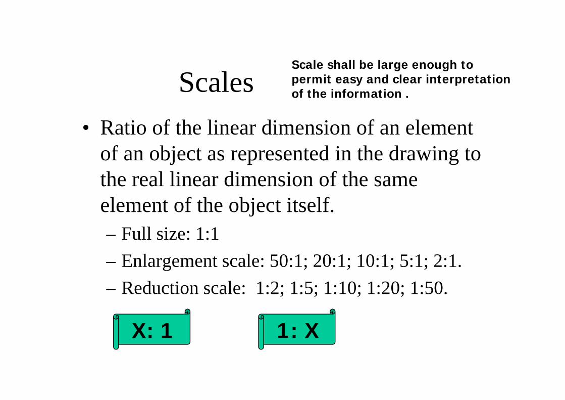
Scales• Ratio of the linear dimension of an element
of an object as represented in the drawing to the real linear dimension of the same element of the object itself. – Full size: 1:1– Enlargement scale: 50:1; 20:1; 10:1; 5:1; 2:1.– Reduction scale: 1:2; 1:5; 1:10; 1:20; 1:50.
X: 1 1: X
Scale shall be large enough to permit easy and clear interpretation of the information .
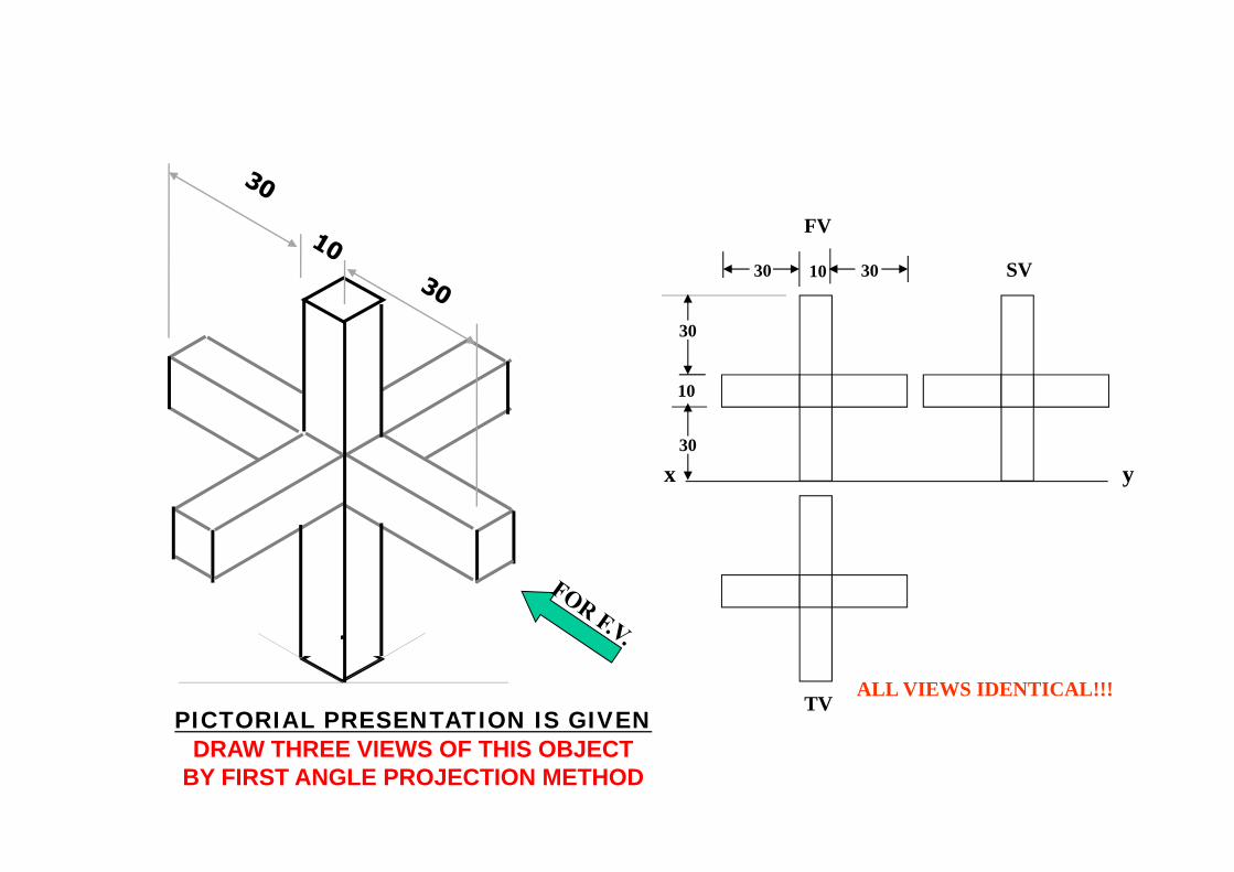
SV
TV
yx
FV
30
30
10
30 10 30
ALL VIEWS IDENTICAL!!!PICTORIAL PRESENTATION IS GIVEN
DRAW THREE VIEWS OF THIS OBJECTBY FIRST ANGLE PROJECTION METHOD

x y
FV35
35
10
TV
302010
40
70
PICTORIAL PRESENTATION IS GIVENDRAW FV AND TV OF THIS OBJECT
BY FIRST ANGLE PROJECTION METHOD Mistakes !!!!!
10
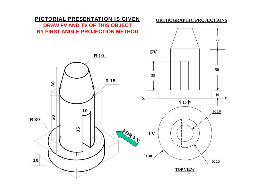
R 10
R 15R 30
TV
10
30
50
10
35
FV
X Y
PICTORIAL PRESENTATION IS GIVENDRAW FV AND TV OF THIS OBJECT
BY FIRST ANGLE PROJECTION METHOD
ORTHOGRAPHIC PROJECTIONS
TOP VIEW
R 10
R 15
R 30
10
3050
10
35
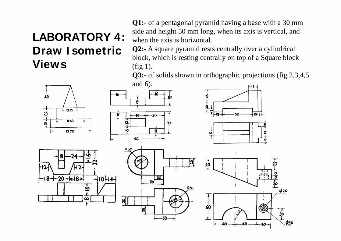
LABORATORY 4: Draw Isometric Views
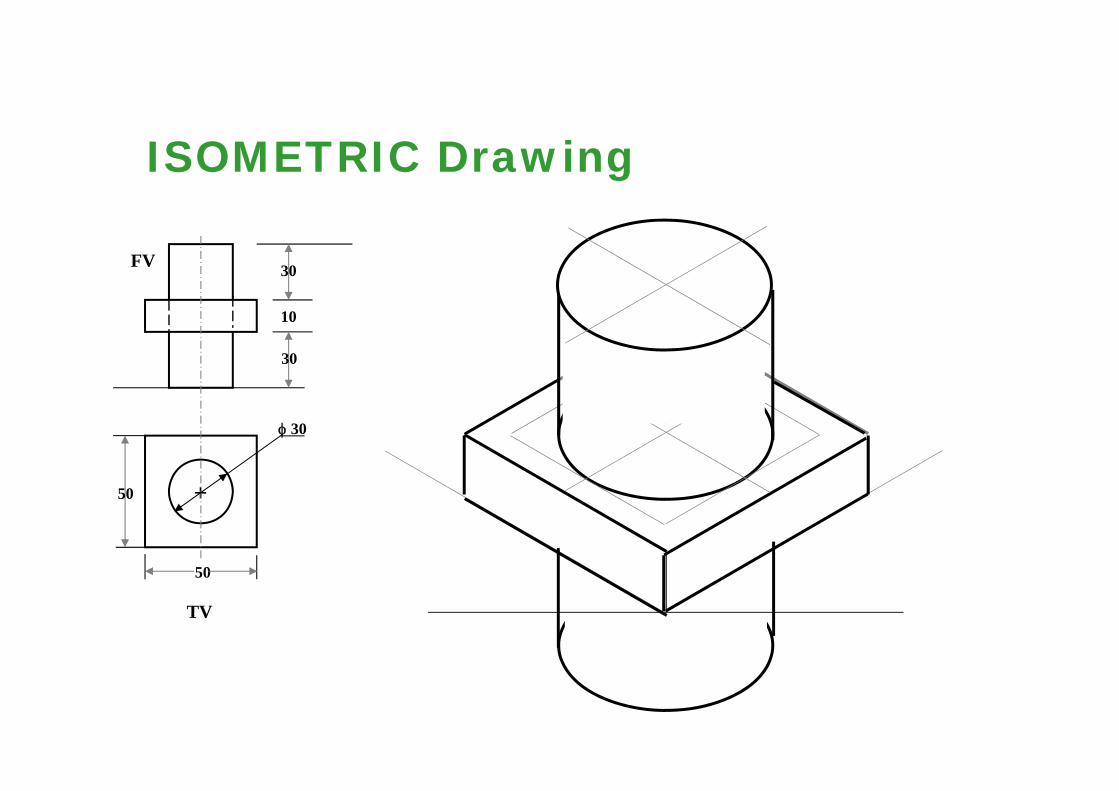
Q1:- of a pentagonal pyramid having a base with a 30 mm side and height 50 mm long, when its axis is vertical, and when the axis is horizontal.Q2:- A square pyramid rests centrally over a cylindrical block, which is resting centrally on top of a Square block (fig 1).Q3:- of solids shown in orthographic projections (fig 2,3,4,5 and 6).
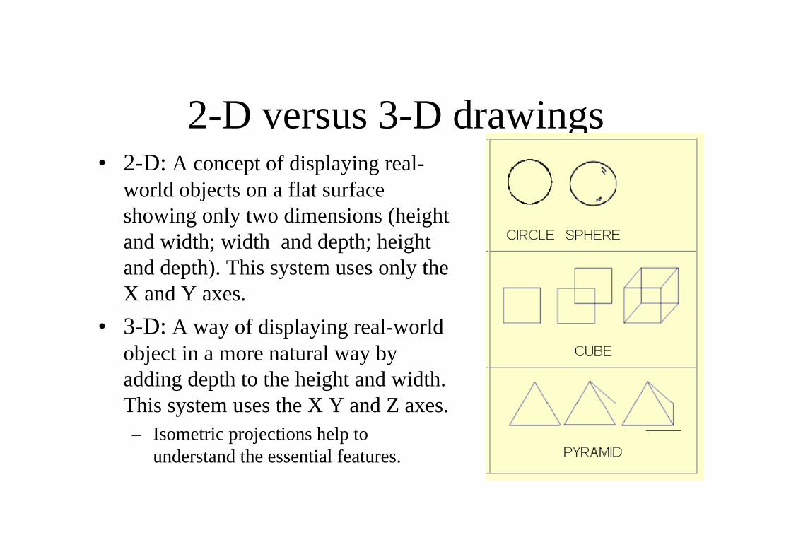
2-D versus 3-D drawings• 2-D: A concept of displaying real-
world objects on a flat surface showing only two dimensions (height and width; width and depth; height and depth). This system uses only the X and Y axes.
• 3-D: A way of displaying real-world object in a more natural way by adding depth to the height and width. This system uses the X Y and Z axes.– Isometric projections help to
understand the essential features.
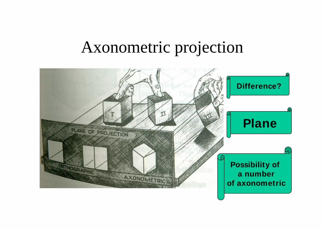
Axonometric projection
Difference?
Plane
Possibility of a number
of axonometric
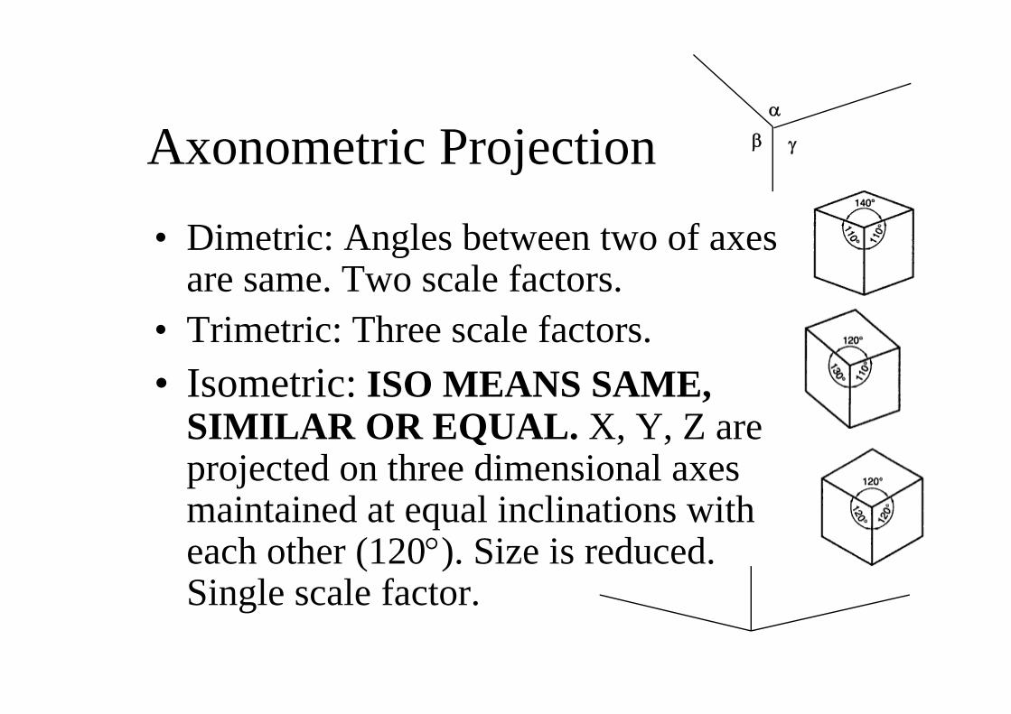
Axonometric Projection• Dimetric: Angles between two of axes
are same. Two scale factors.• Trimetric: Three scale factors.• Isometric: ISO MEANS SAME,
SIMILAR OR EQUAL. X, Y, Z are projected on three dimensional axes maintained at equal inclinations with each other (120°). Size is reduced. Single scale factor.
α
γβ
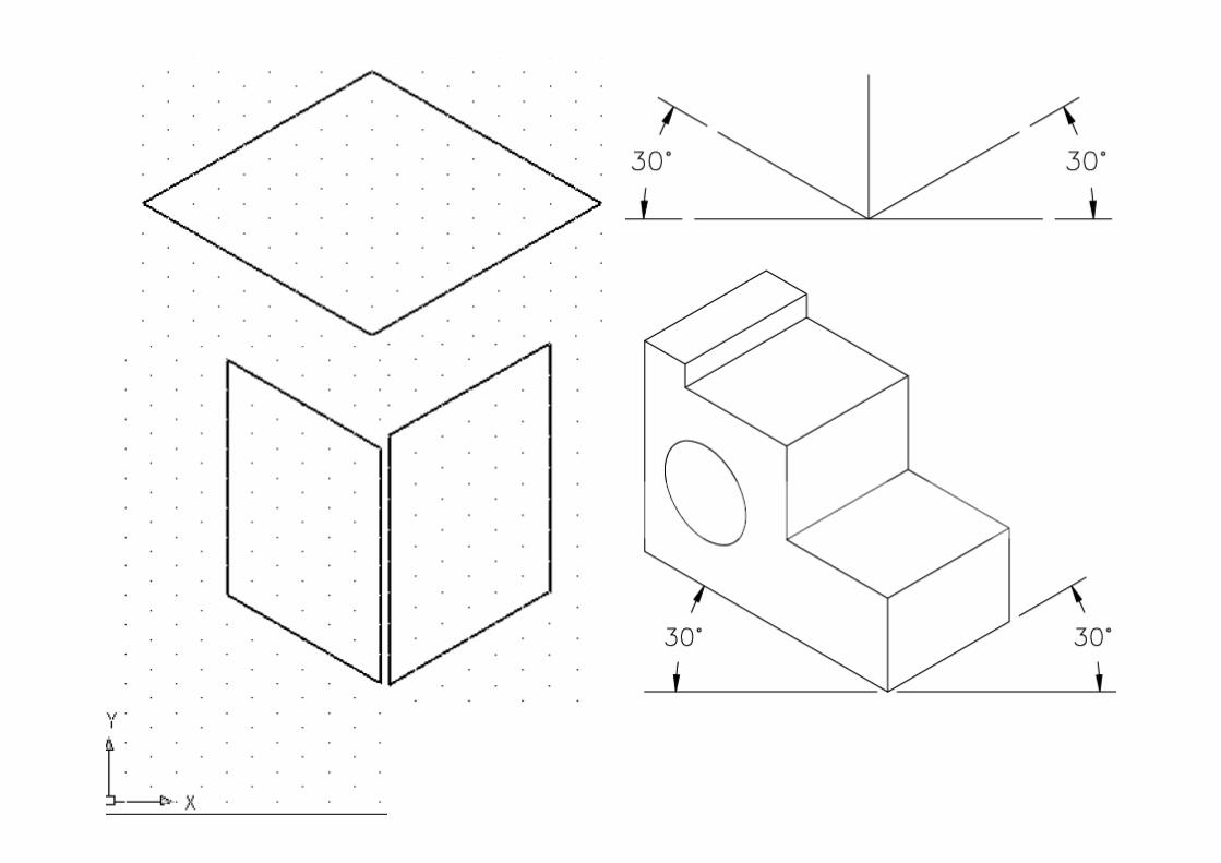
Isometric Planes
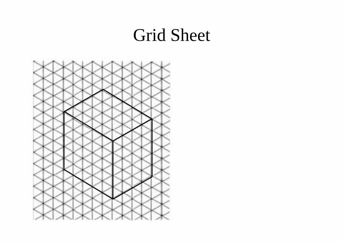
Grid Sheet
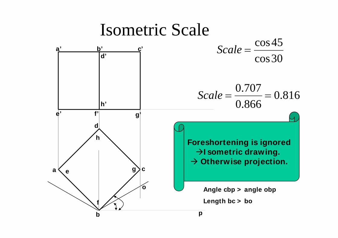
Isometric Scale
h
d
a cg
f
e
b
b’
e’ g’f’
a’ c’
h’
d’ 30cos45cos
=Scale
816.0866.0707.0
==Scale
Foreshortening is ignoredIsometric drawing.
Otherwise projection.
o Angle cbp > angle obp
Length bc > bo
p
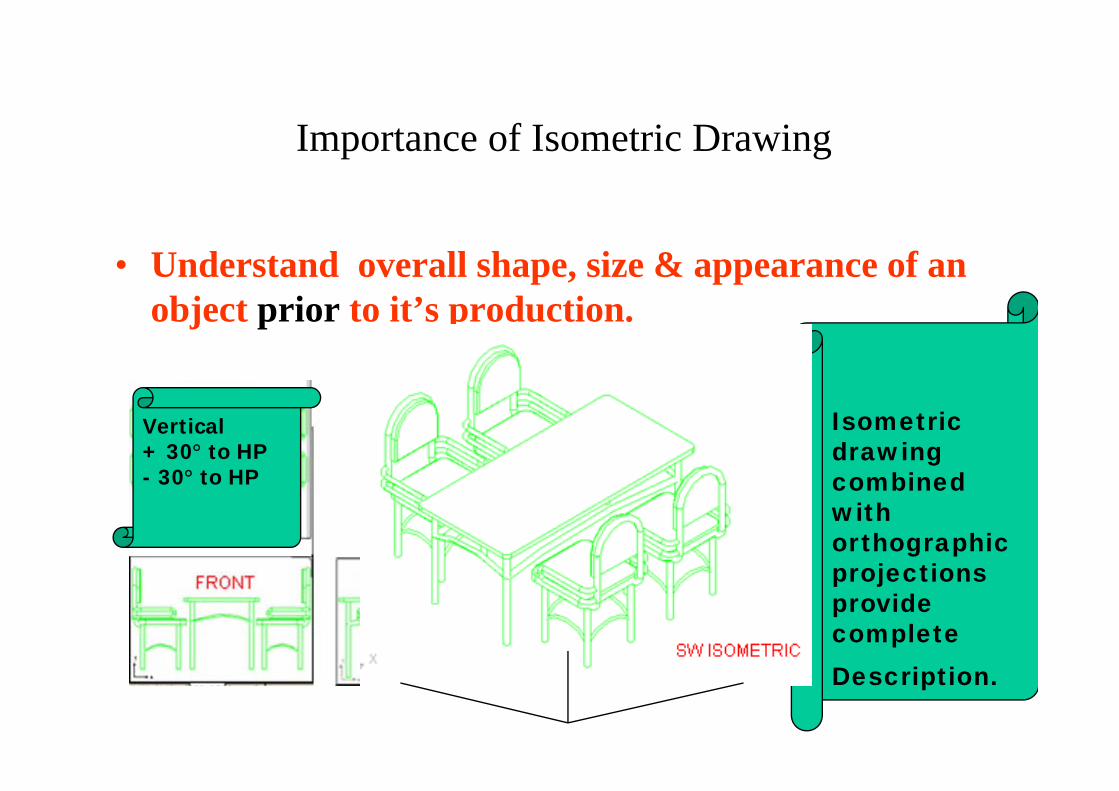
Importance of Isometric Drawing
• Understand overall shape, size & appearance of an object prior to it’s production.
Isometric drawing combined with orthographic projections provide completeDescription.
Vertical+ 30° to HP- 30° to HP
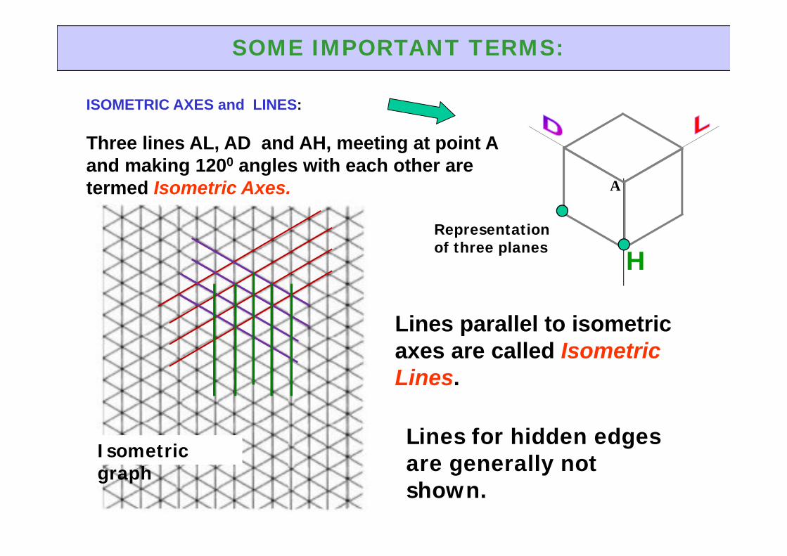
ISOMETRIC AXES and LINES:
Three lines AL, AD and AH, meeting at point A and making 1200 angles with each other are termed Isometric Axes.
H
A
SOME IMPORTANT TERMS:
Lines parallel to isometric axes are called Isometric Lines.
Lines for hidden edges are generally not shown.
Isometric graph
Representation of three planes
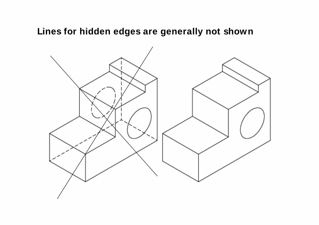
Lines for hidden edges are generally not shown
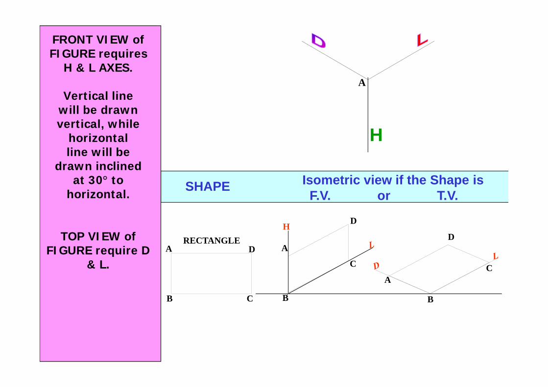
SHAPE Isometric view if the Shape isF.V. or T.V.
A
B
RECTANGLED
C
H D
A
B
C
A
B
D
C
FRONT VIEW of FIGURE requires
H & L AXES.
Vertical linewill be drawn vertical, while
horizontalline will be
drawn inclinedat 30° to
horizontal.
TOP VIEW of FIGURE require D
& L.
H
A
SHAPE Isometric view if the Shape isF.V. or T.V.
TRIANGLEH
1
2
3
A
B3
1
2
A
B
3
1
2
A
B
H
1
2 3
4PENTAGON
A
B C
D
E 1
2
3
4
A
B
C
D
E
1
2
3
4
A
B
C
DE
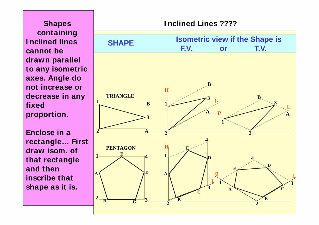
Shapes containing
Inclined lines cannot be drawn parallel to any isometric axes. Angle do not increase or decrease in any fixed proportion.
Enclose in a rectangle… First draw isom. of that rectangle and then inscribe that shape as it is.
Inclined Lines ????
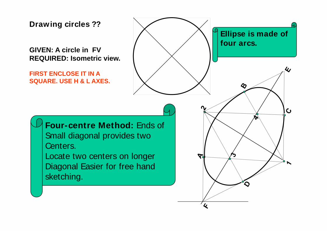
GIVEN: A circle in FVREQUIRED: Isometric view.
FIRST ENCLOSE IT IN A SQUARE. USE H & L AXES.
Four-centre Method: Ends of Small diagonal provides twoCenters. Locate two centers on longer Diagonal Easier for free hand sketching.
Ellipse is made of four arcs.
Drawing circles ??
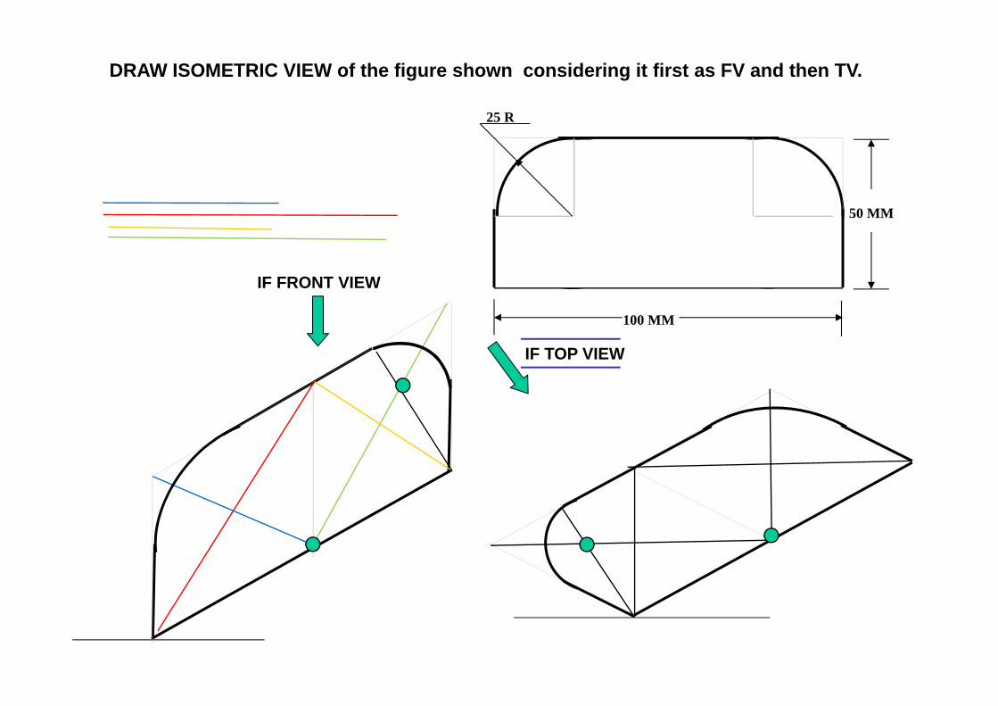
25 R
100 MM
50 MM
IF TOP VIEW
IF FRONT VIEW
DRAW ISOMETRIC VIEW of the figure shown considering it first as FV and then TV.
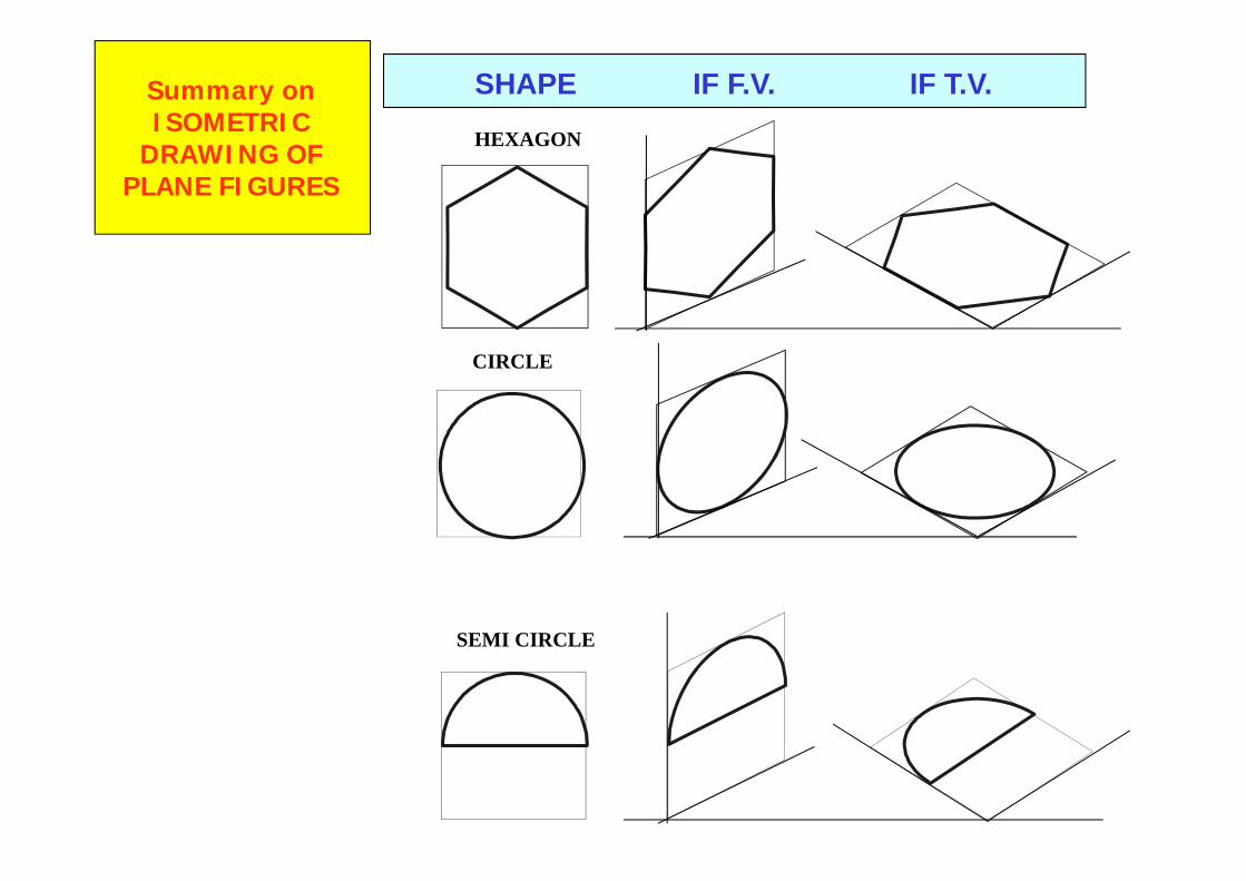
CIRCLE
HEXAGON
SEMI CIRCLE
Summary onISOMETRIC
DRAWING OFPLANE FIGURES
SHAPE IF F.V. IF T.V.
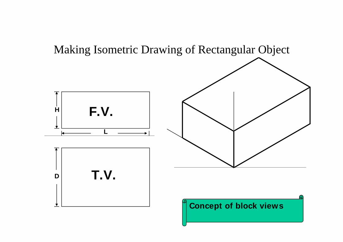
Making Isometric Drawing of Rectangular Object
L
H
D
F.V.
T.V.
Concept of block views
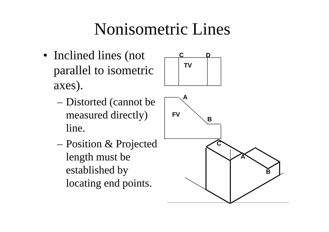
Nonisometric Lines• Inclined lines (not
parallel to isometric axes).– Distorted (cannot be
measured directly) line.
– Position & Projected length must be established by locating end points.
FV
TV
A
B
C D
A
B
C
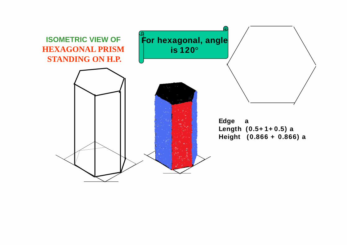
ISOMETRIC VIEW OFHEXAGONAL PRISM
STANDING ON H.P.
For hexagonal, angleis 120°
Edge aLength (0.5+1+0.5) aHeight (0.866 + 0.866) a
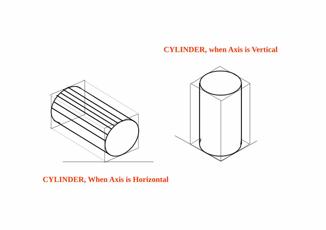
CYLINDER, When Axis is Horizontal
CYLINDER, when Axis is Vertical
.
40
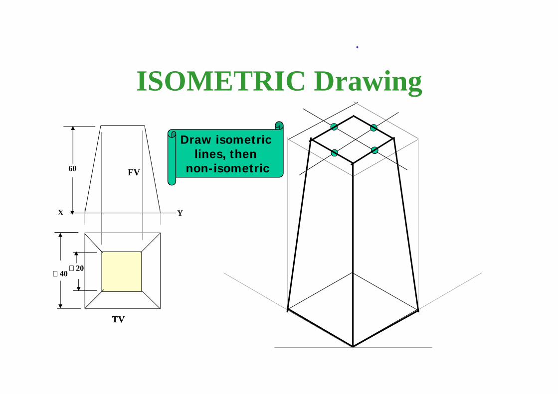
ISOMETRIC Drawing
Draw isometric lines, then
non-isometric
20
60
X Y
FV
TV
FV
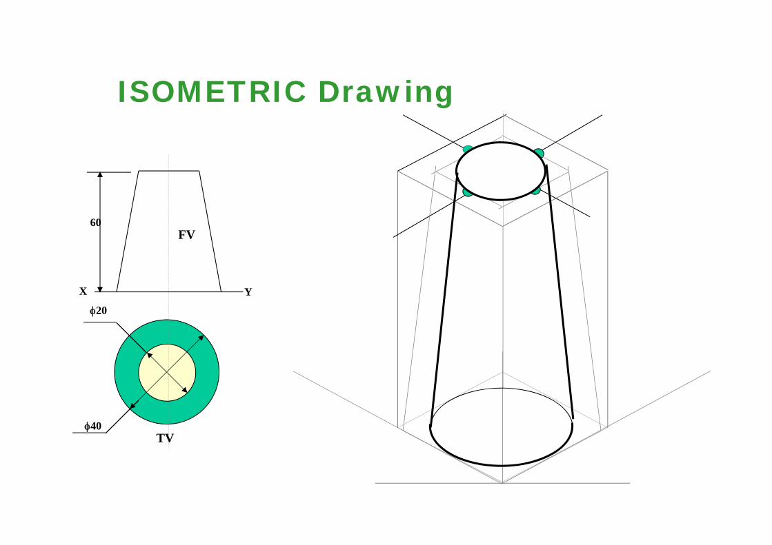
TVφ40
φ20
60
X Y
ISOMETRIC Drawing
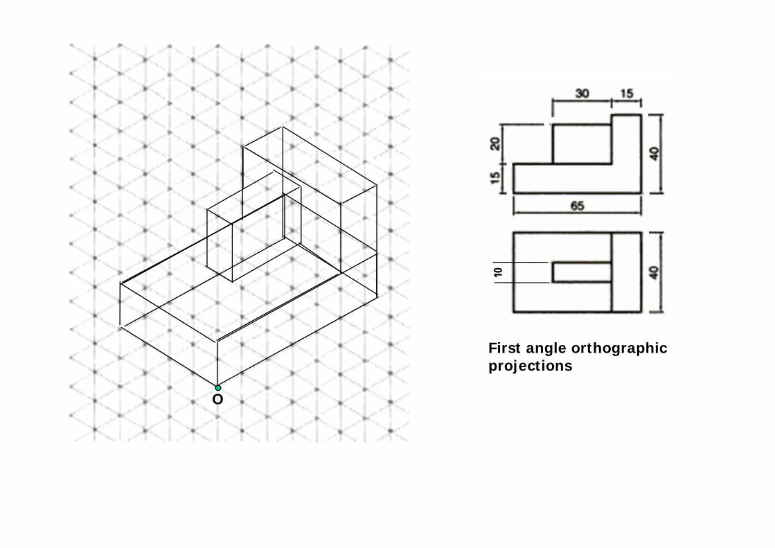
First angle orthographic projections
O
10
50
50
φ 30
30
10
30
+
FV
TV
ISOMETRIC Drawing
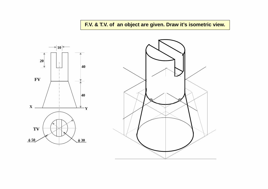
X Y
φ 30φ 50
10
4020
40
FV
TV
F.V. & T.V. of an object are given. Draw it’s isometric view.
O
FT
x y
FV SV
TV
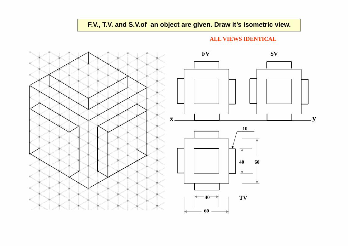
ALL VIEWS IDENTICAL
40 60
60
40
10
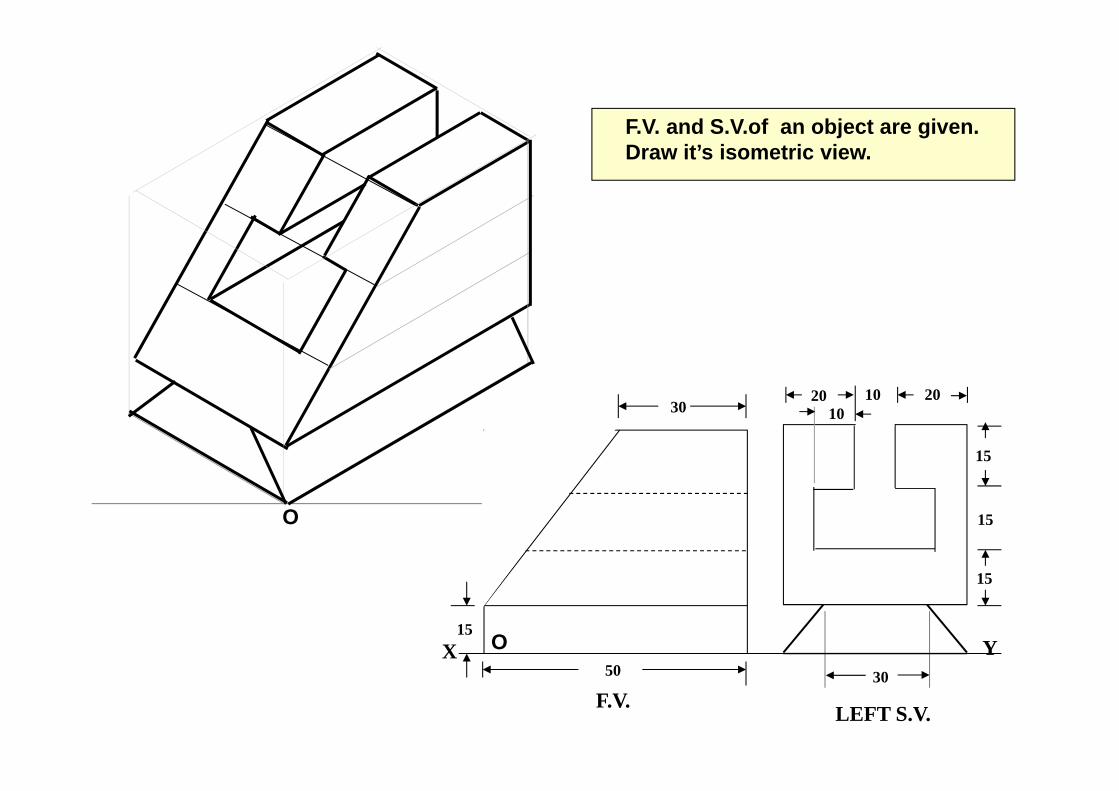
F.V., T.V. and S.V.of an object are given. Draw it’s isometric view.
FT
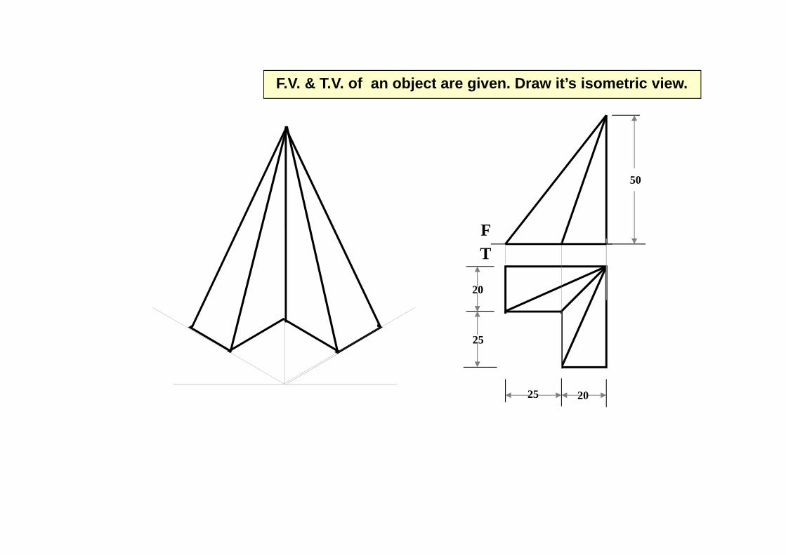
50
20
25
25 20
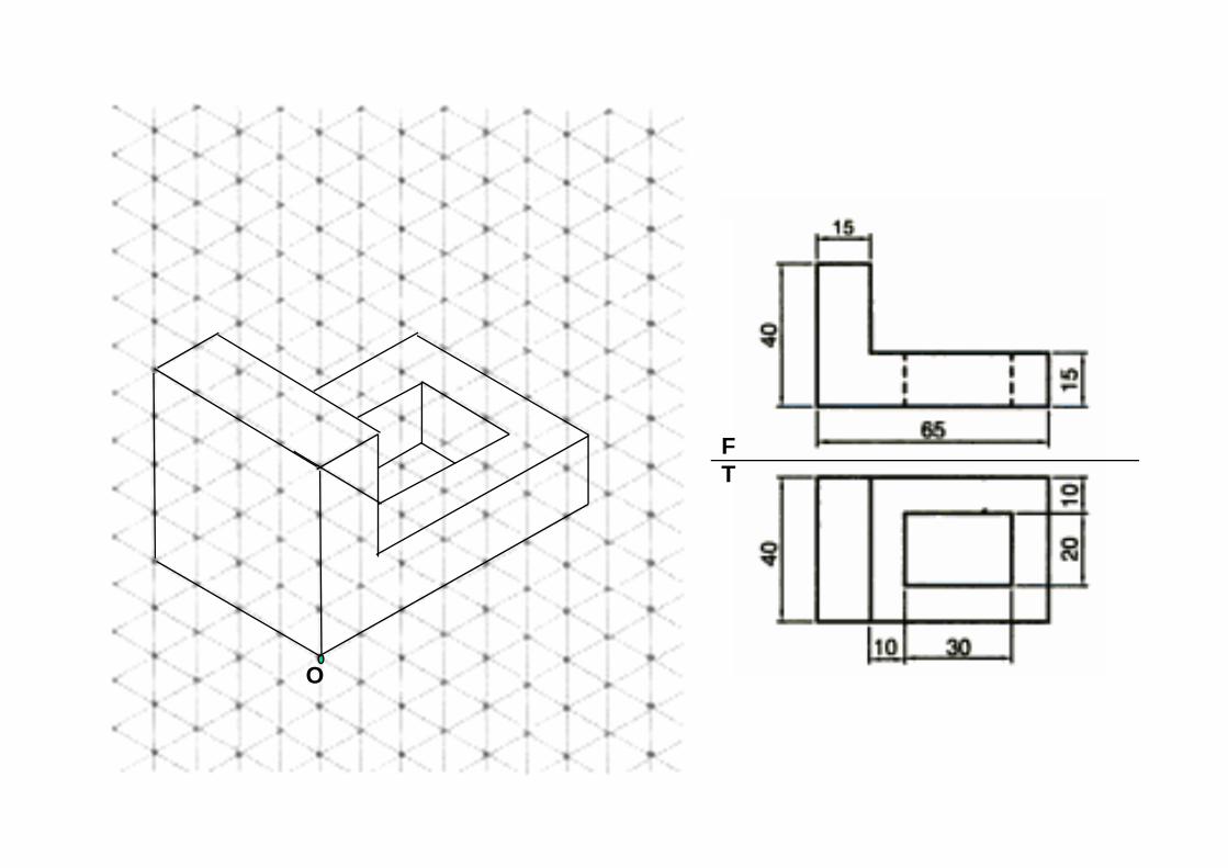
F.V. & T.V. of an object are given. Draw it’s isometric view.
O
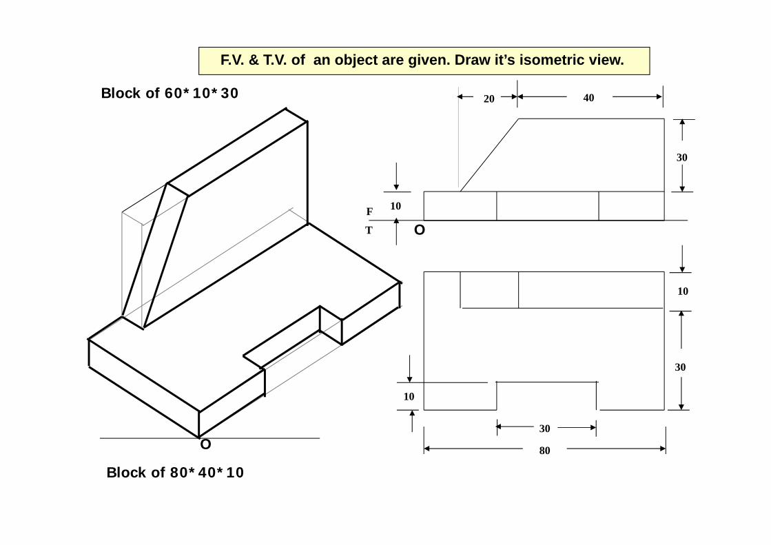
O10
10
30
10
30
4020
80
30
F
T
F.V. & T.V. of an object are given. Draw it’s isometric view.
Block of 80*40*10
Block of 60*10*30
O
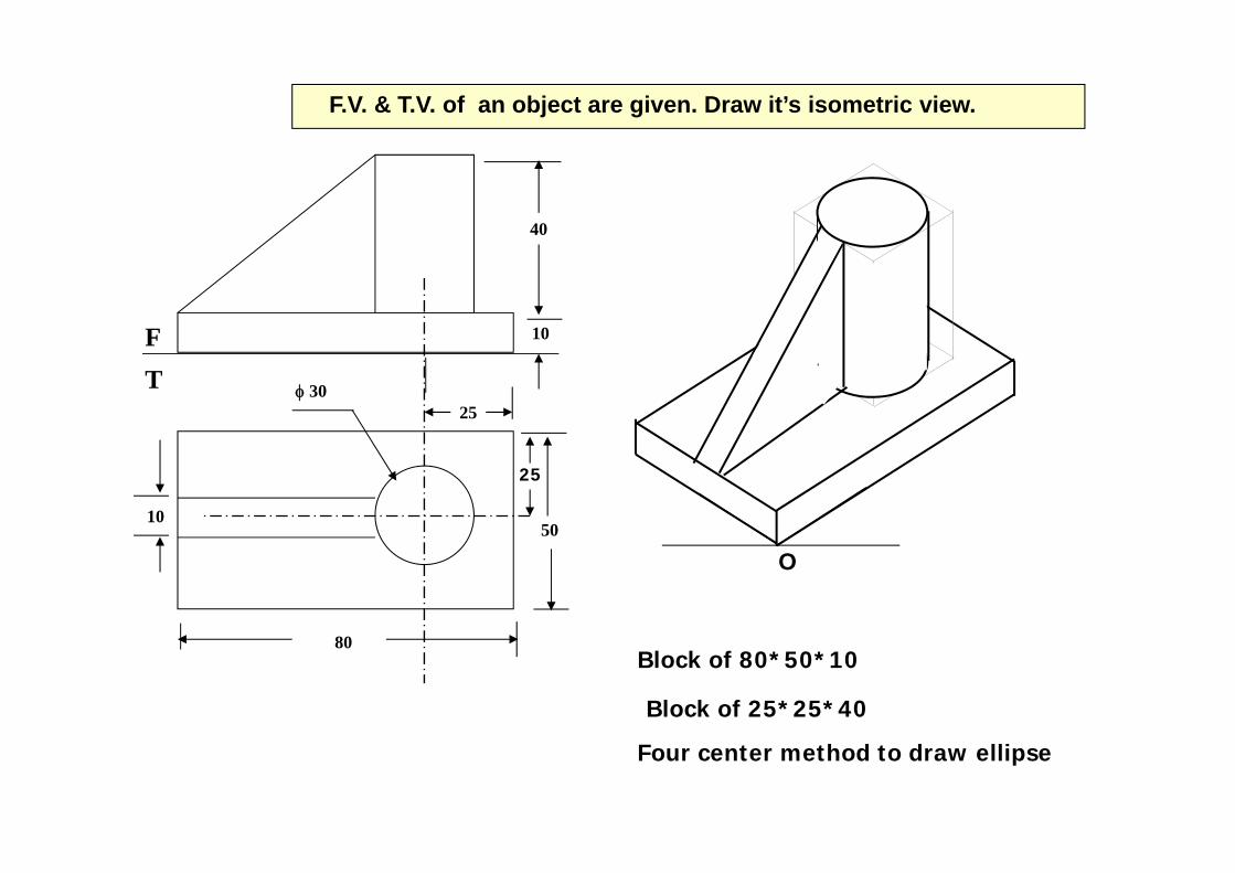
F.V. & T.V. of an object are given. Draw it’s isometric view.
40
10
50
80
10
φ 3025
FT
25
Block of 80*50*10
Block of 25*25*40
Four center method to draw ellipse
O
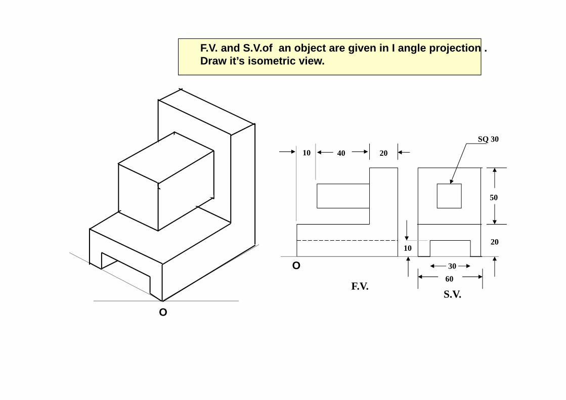
F.V. and S.V.of an object are given in I angle projection . Draw it’s isometric view.
40 20
SQ 30
20
50
6030
10
F.V.S.V.
O
10
O
FV
TV
X YO
40
10
25
25
30 R
10
100103010
R 10
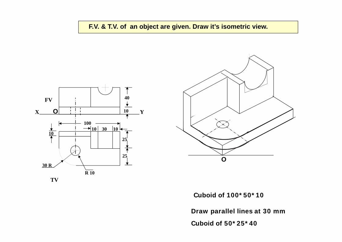
F.V. & T.V. of an object are given. Draw it’s isometric view.
Cuboid of 100*50*10
Draw parallel lines at 30 mm
Cuboid of 50*25*40
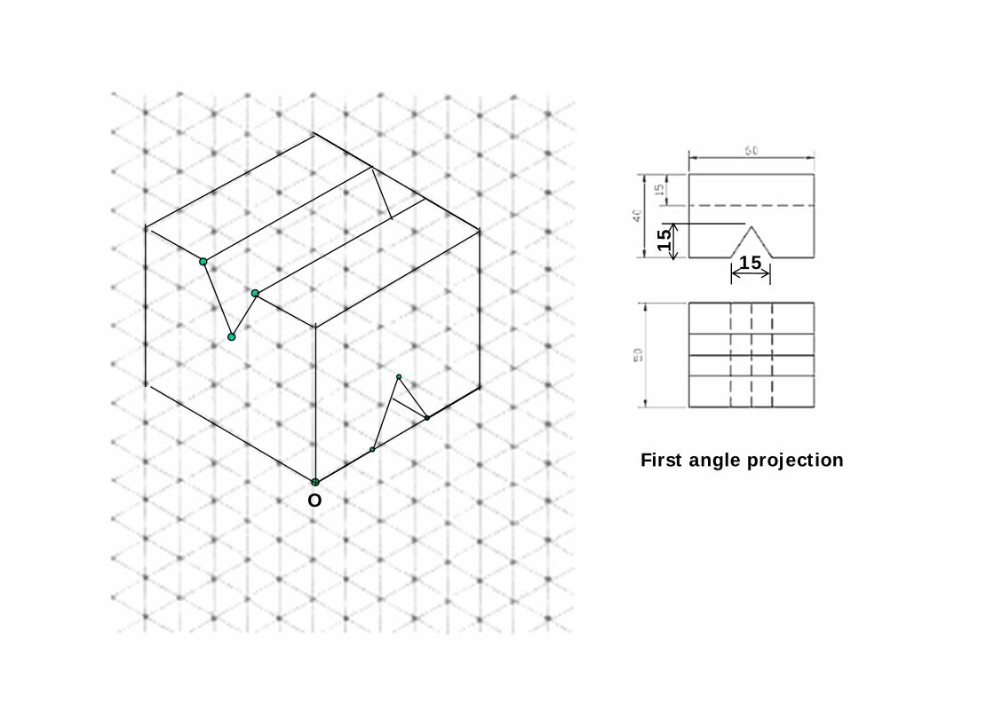
First angle projection
O
15
15
O
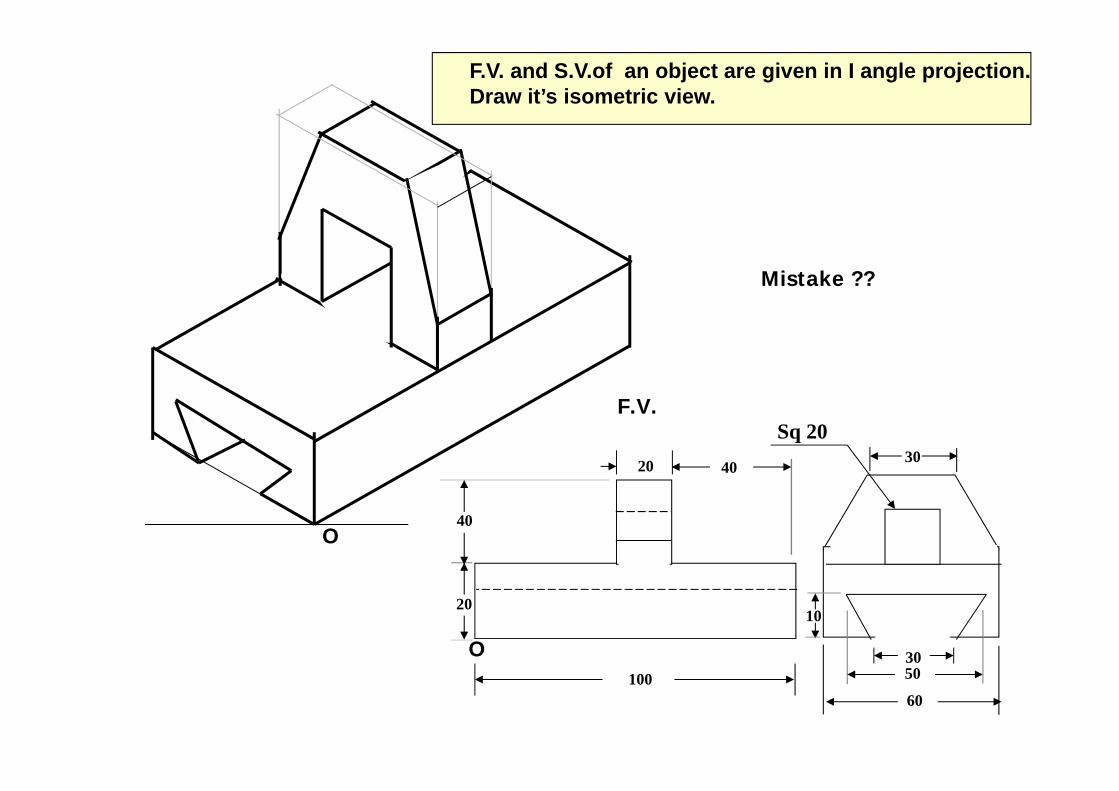
F.V. and S.V.of an object are given in I angle projection. Draw it’s isometric view.
Sq 20
O
20
2010
30
60
30
40
100 50
40
F.V.
Mistake ??
40
40
LSV
Y
25
25
1050
FV
X
10 10
15O
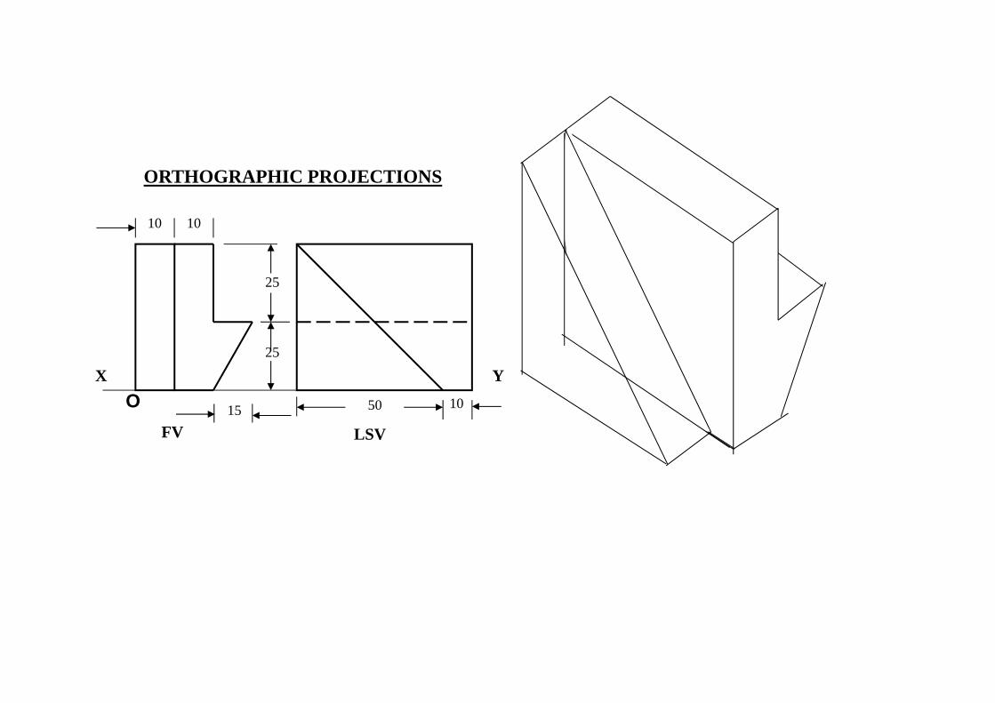
ORTHOGRAPHIC PROJECTIONS
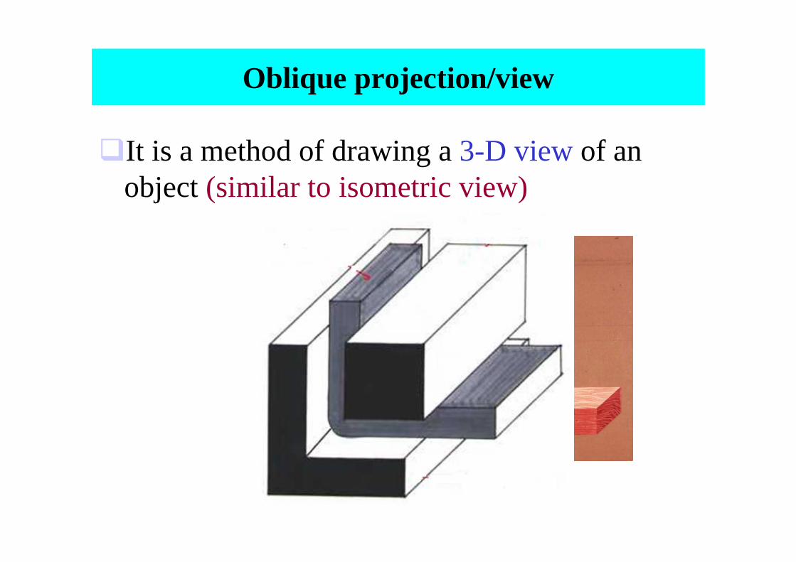
Oblique projection/view
It is a method of drawing a 3-D view of an object (similar to isometric view)
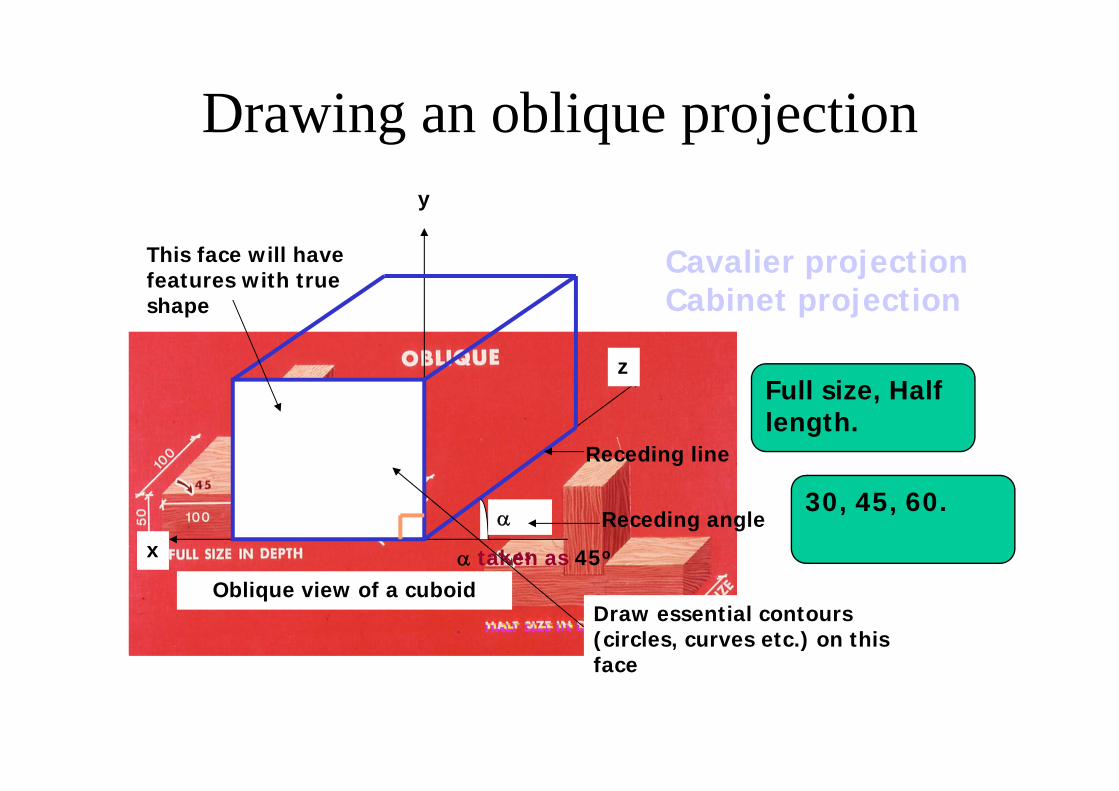
Drawing an oblique projection
Full size, Half length.
30, 45, 60.
Cavalier projectionCabinet projection
α
α taken as 45o
Oblique view of a cuboid
x
y
z
Receding angle
Receding line
This face will have features with true shape
Draw essential contours (circles, curves etc.) on this face

Cavalier & Cabinet projections
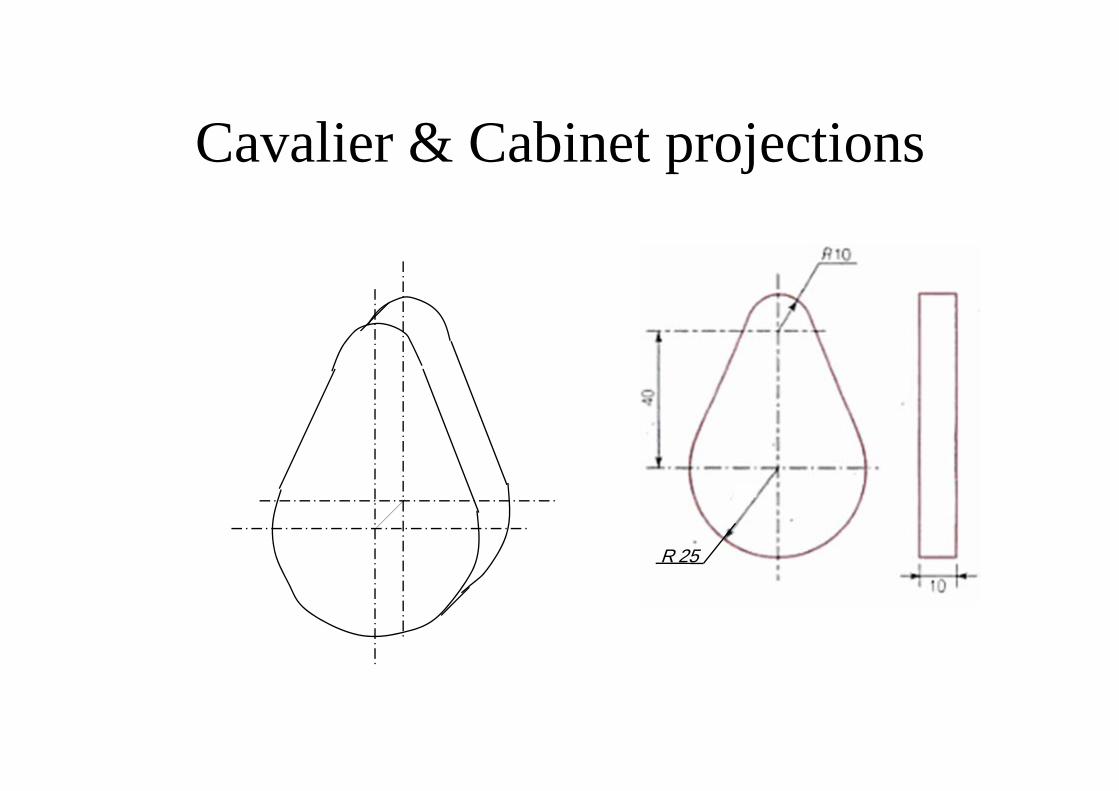
R 25
Cavalier & Cabinet projections
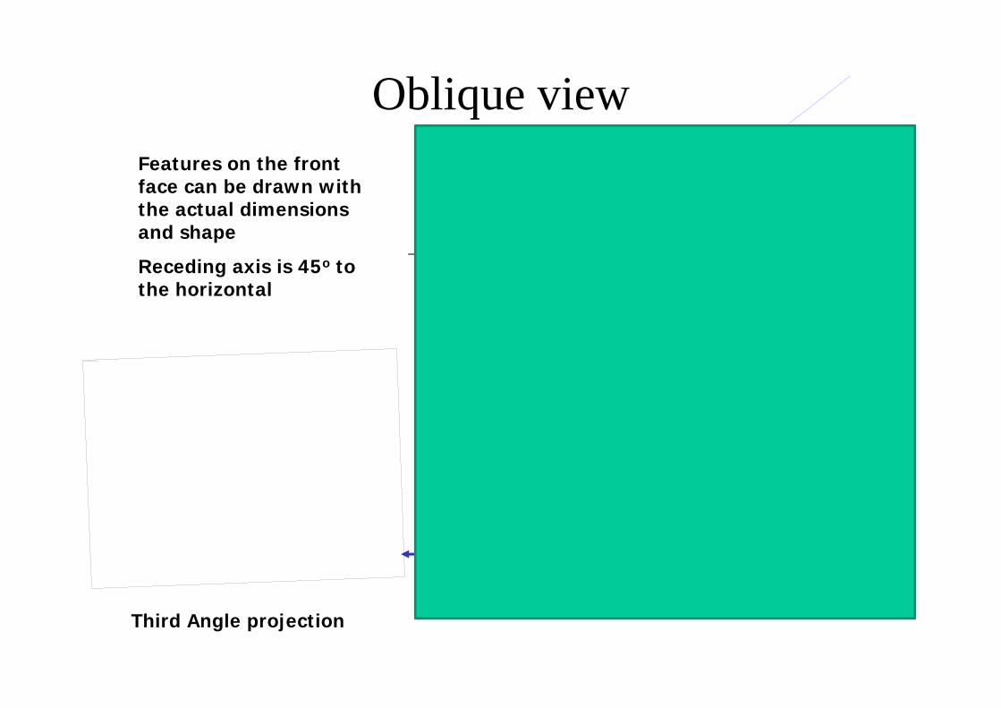
Oblique view
45o
Features on the front face can be drawn with the actual dimensions and shape
Receding axis is 45o to the horizontal
Receding axis
x
z
Third Angle projection
This image cannot currently be displayed.
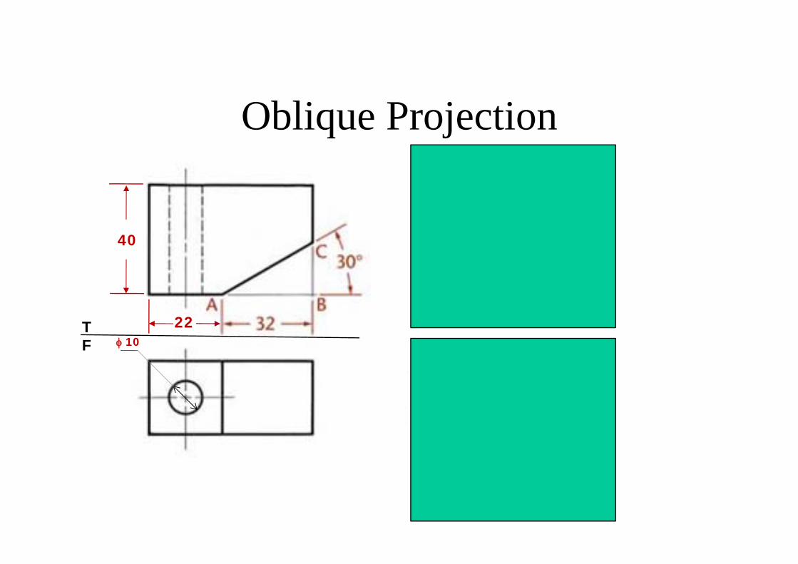
Oblique Projection
φ 10
22
40
TF
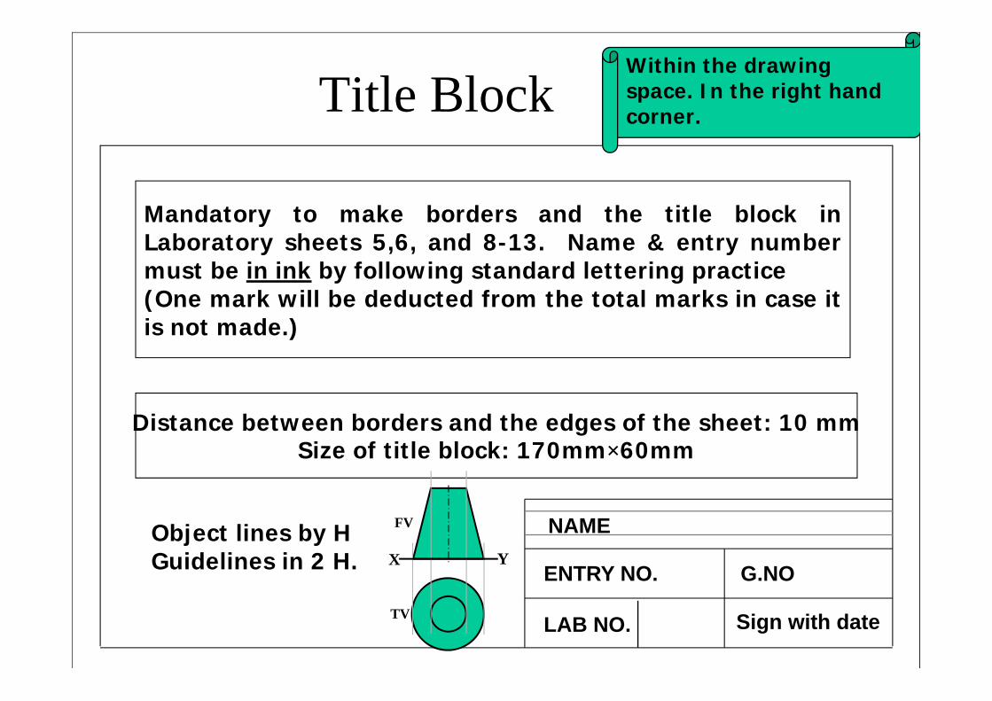
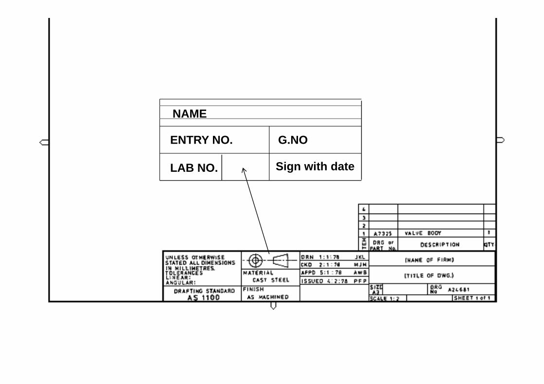
Distance between borders and the edges of the sheet: 10 mmSize of title block: 170mm×60mm
Mandatory to make borders and the title block inLaboratory sheets 5,6, and 8-13. Name & entry numbermust be in ink by following standard lettering practice(One mark will be deducted from the total marks in case itis not made.)
Title Block
NAME
ENTRY NO. G.NO
LAB NO. Sign with date
Object lines by HGuidelines in 2 H.
Within the drawing space. In the right hand corner.
FV
TV
X Y
NAME
ENTRY NO. G.NO
LAB NO. Sign with date
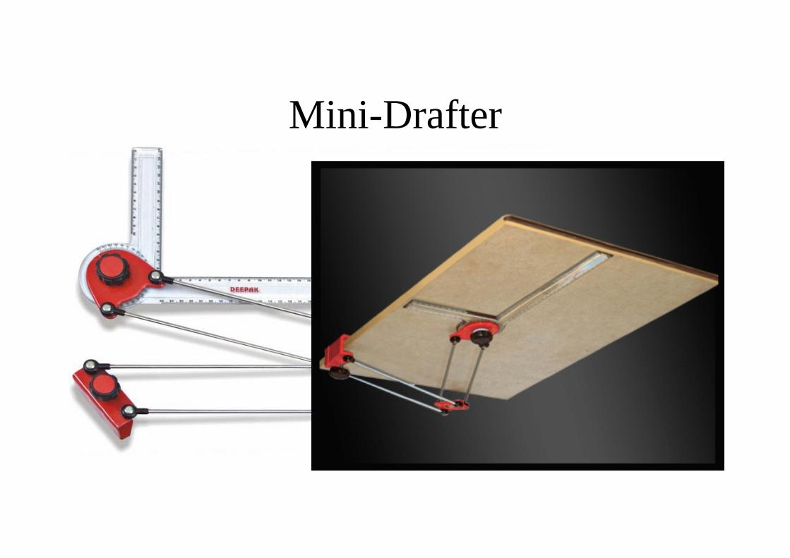
Mini-Drafter
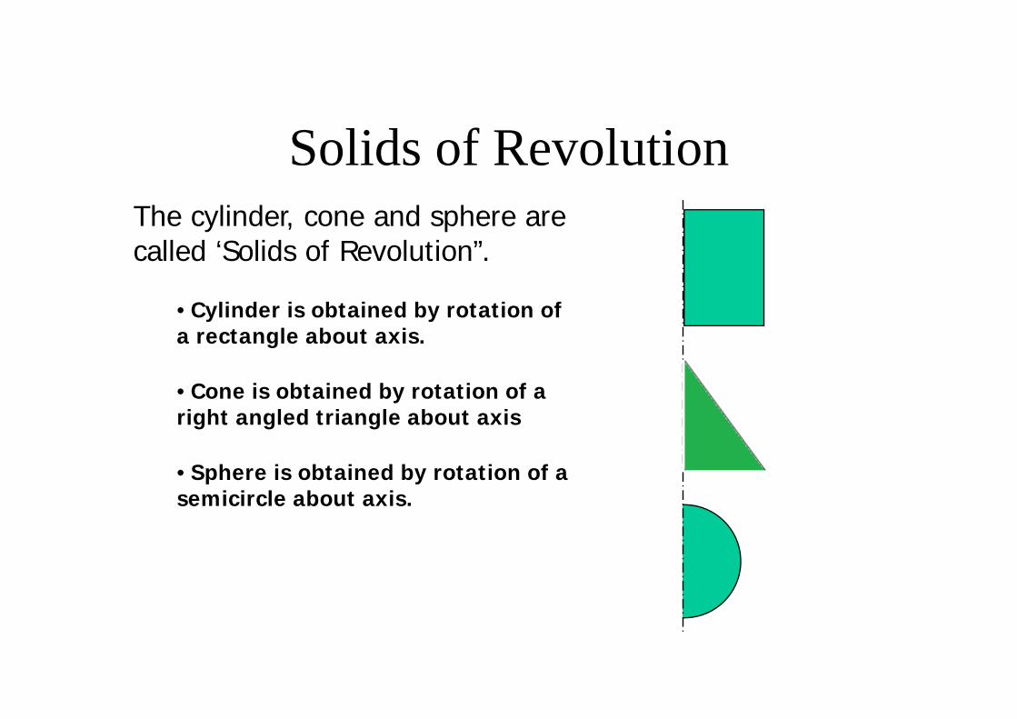
Solids of RevolutionThe cylinder, cone and sphere are called ‘Solids of Revolution”.
• Cylinder is obtained by rotation of a rectangle about axis.
• Cone is obtained by rotation of a right angled triangle about axis
• Sphere is obtained by rotation of a semicircle about axis.
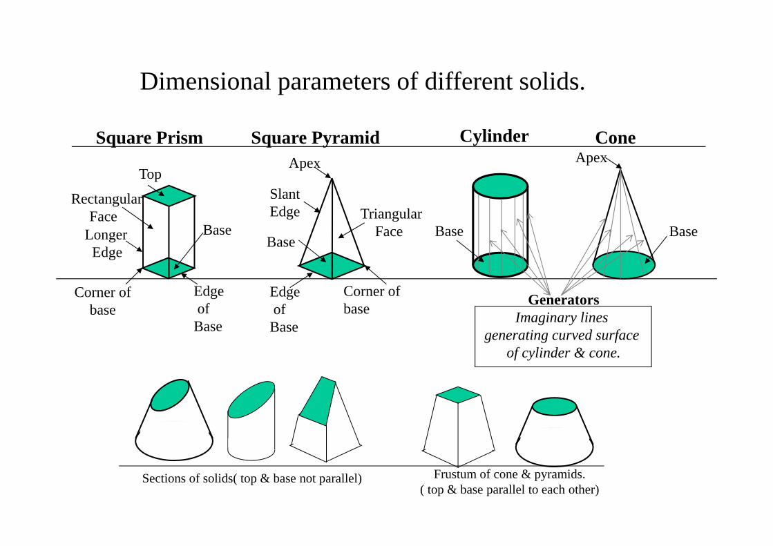
Dimensional parameters of different solids.
Top
RectangularFace
Longer Edge
Base
Edgeof
Base
Corner of base
Corner of base
TriangularFace
Slant Edge
Base
Apex
Square Prism Square Pyramid Cylinder Cone
Edgeof
Base
Base
Apex
Base
GeneratorsImaginary lines
generating curved surface of cylinder & cone.
Sections of solids( top & base not parallel) Frustum of cone & pyramids.( top & base parallel to each other)
115
F
T aT
o
oF
dFcFbFaF
o1
d1
b1c1
a1
a’1
d’1 c’1
b’1
o’1
a1
(APEX NEARER TO V.P).
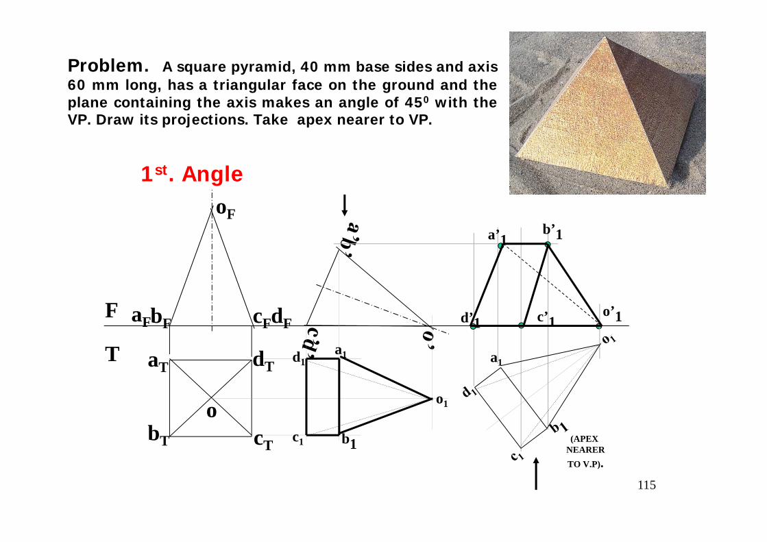
Problem. A square pyramid, 40 mm base sides and axis60 mm long, has a triangular face on the ground and theplane containing the axis makes an angle of 450 with theVP. Draw its projections. Take apex nearer to VP.
1st. Angle
bT cT
dT
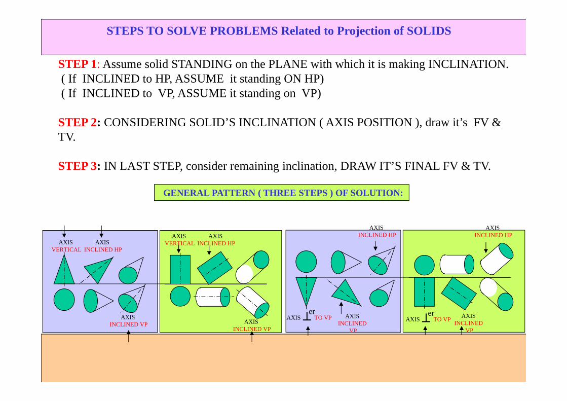
STEPS TO SOLVE PROBLEMS Related to Projection of SOLIDS
STEP 1: Assume solid STANDING on the PLANE with which it is making INCLINATION.( If INCLINED to HP, ASSUME it standing ON HP)( If INCLINED to VP, ASSUME it standing on VP)
STEP 2: CONSIDERING SOLID’S INCLINATION ( AXIS POSITION ), draw it’s FV & TV.
STEP 3: IN LAST STEP, consider remaining inclination, DRAW IT’S FINAL FV & TV.
AXIS VERTICAL
AXIS INCLINED HP
AXIS INCLINED VP
AXIS VERTICAL
AXIS INCLINED HP
AXIS INCLINED VP
AXIS TO VPer
AXIS INCLINED
VP
AXIS INCLINED HP
AXIS TO VPer AXIS
INCLINEDVP
AXIS INCLINED HP
GENERAL PATTERN ( THREE STEPS ) OF SOLUTION:
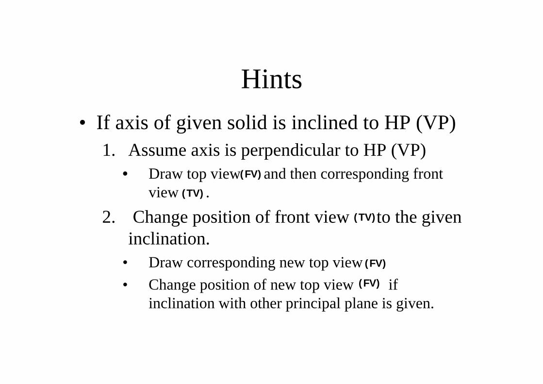
Hints• If axis of given solid is inclined to HP (VP)
1. Assume axis is perpendicular to HP (VP)• Draw top view and then corresponding front
view .
2. Change position of front view to the given inclination.
• Draw corresponding new top view • Change position of new top view if
inclination with other principal plane is given.
(FV)
(FV)
(FV)
(TV)
(TV)
118
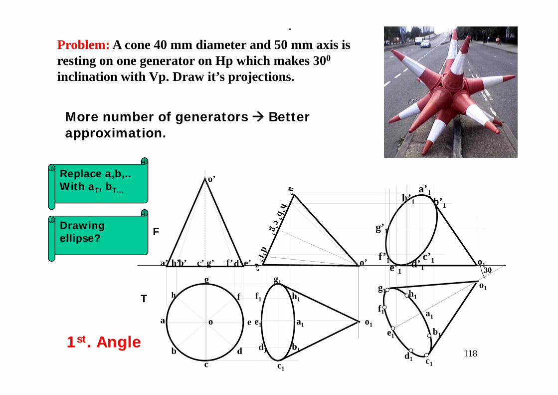
Problem: A cone 40 mm diameter and 50 mm axis is resting on one generator on Hp which makes 300
inclination with Vp. Draw it’s projections.
h
a
bc
d
e
g
f
a’ b’ d’ e’c’ g’ f’h’
o’
o’
a1
h1
g1
f1
e1
d1
c1
b1
a1
c1
b1
d1
e1
f1
g1 h1
o1
a’1b’1
c’1d’1e’1
f’1
g’1
h’1
o1
o1
30
.
1st. Angle
T
F
o
More number of generators Better approximation.
Replace a,b,.. With aT, bT…
Drawing ellipse?
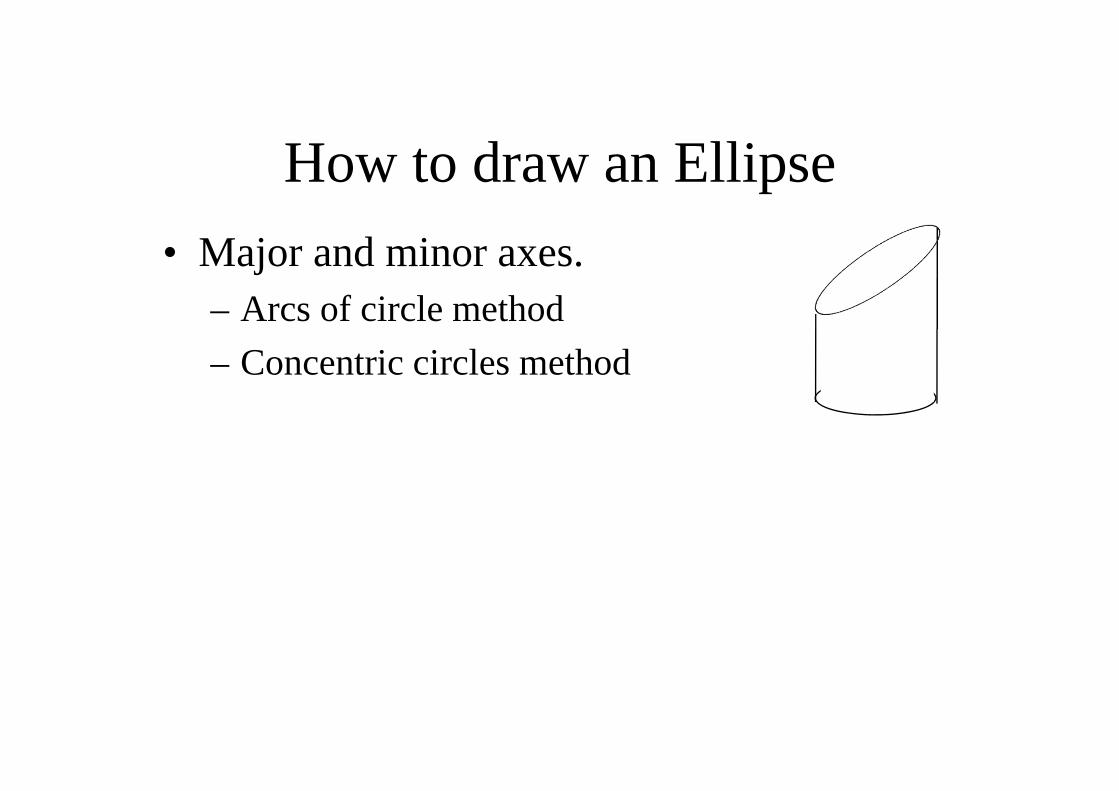
How to draw an Ellipse • Major and minor axes.
– Arcs of circle method– Concentric circles method
F1 F21 2 3 4 A B
C
D
p1
p2
p3
p4
ARCS OF CIRCLE METHOD
O
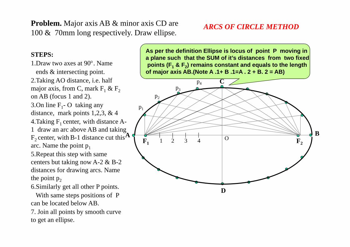
Problem. Major axis AB & minor axis CD are 100 & 70mm long respectively. Draw ellipse.
STEPS:1.Draw two axes at 90°. Name
ends & intersecting point.2.Taking AO distance, i.e. half major axis, from C, mark F1 & F2 on AB (focus 1 and 2).3.On line F1- O taking any distance, mark points 1,2,3, & 44.Taking F1 center, with distance A-1 draw an arc above AB and taking F2 center, with B-1 distance cut this arc. Name the point p15.Repeat this step with same centers but taking now A-2 & B-2 distances for drawing arcs. Name the point p2 6.Similarly get all other P points.
With same steps positions of P can be located below AB. 7. Join all points by smooth curve to get an ellipse.
As per the definition Ellipse is locus of point P moving in a plane such that the SUM of it’s distances from two fixedpoints (F1 & F2) remains constant and equals to the length
of major axis AB.(Note A .1+ B .1=A . 2 + B. 2 = AB)
1
23
4
5
6
78
9
10
BA
D
C
1
2 3 4
5
6
78
9
10
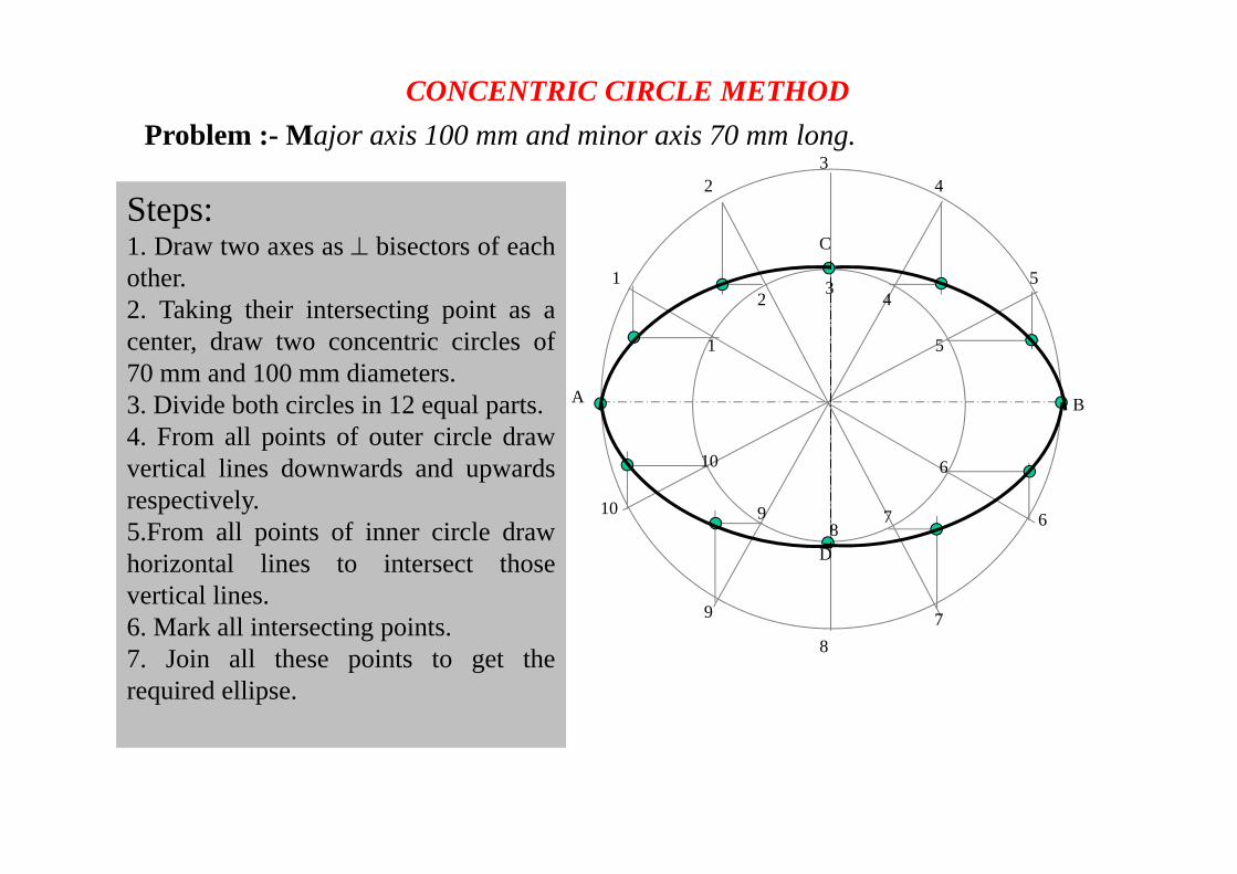
Steps:1. Draw two axes as ⊥ bisectors of eachother.2. Taking their intersecting point as acenter, draw two concentric circles of70 mm and 100 mm diameters.3. Divide both circles in 12 equal parts.4. From all points of outer circle drawvertical lines downwards and upwardsrespectively.5.From all points of inner circle drawhorizontal lines to intersect thosevertical lines.6. Mark all intersecting points.7. Join all these points to get therequired ellipse.
Problem :- Major axis 100 mm and minor axis 70 mm long.CONCENTRIC CIRCLE METHOD
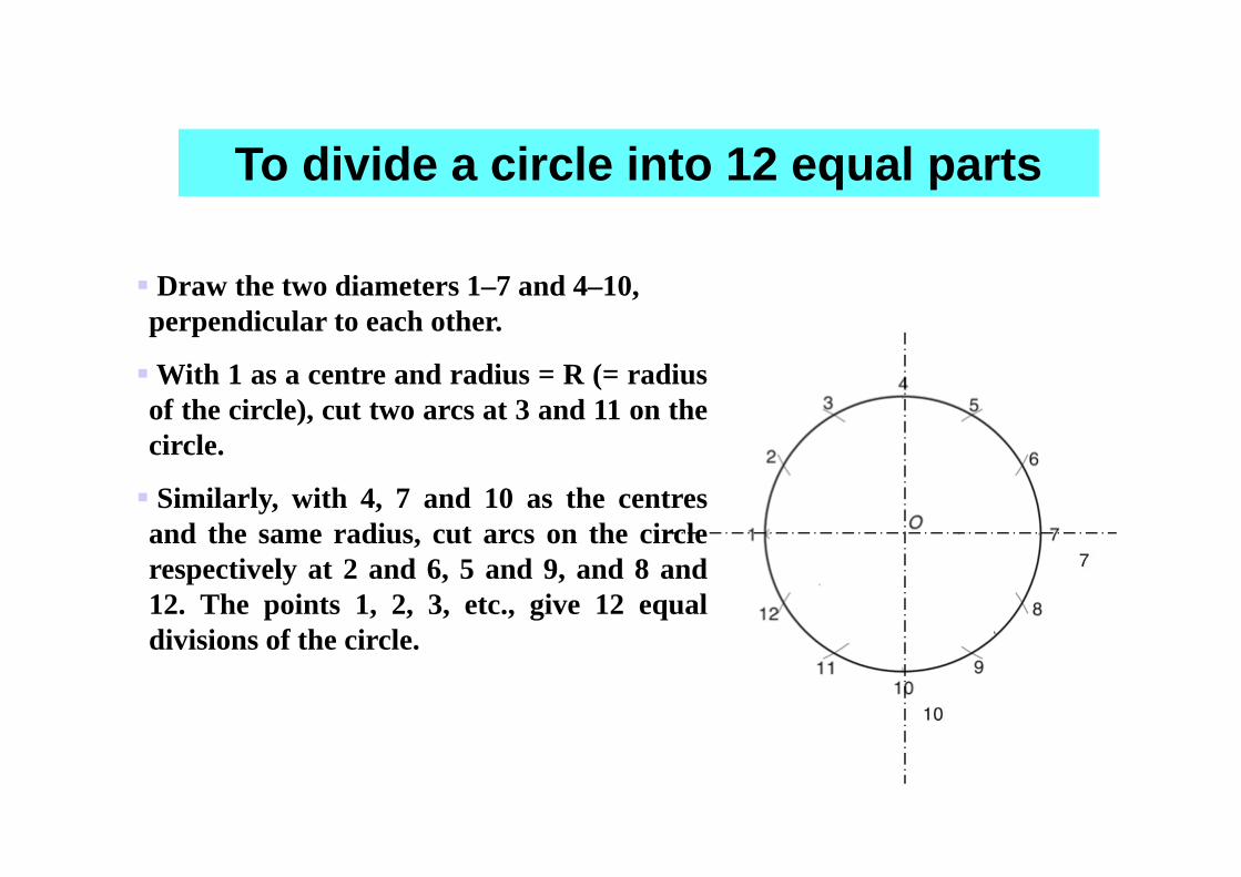
Draw the two diameters 1–7 and 4–10, perpendicular to each other.
With 1 as a centre and radius = R (= radiusof the circle), cut two arcs at 3 and 11 on thecircle.
Similarly, with 4, 7 and 10 as the centresand the same radius, cut arcs on the circlerespectively at 2 and 6, 5 and 9, and 8 and12. The points 1, 2, 3, etc., give 12 equaldivisions of the circle.
To divide a circle into 12 equal parts
aF
bF
aT
bT
F
T
b’1
b1
Ø
θ
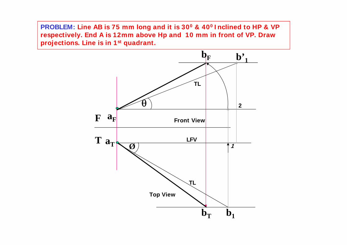
PROBLEM: Line AB is 75 mm long and it is 300 & 400 Inclined to HP & VP respectively. End A is 12mm above Hp and 10 mm in front of VP. Draw projections. Line is in 1st quadrant.
1LFV
TL
TL
Front View
Top View
2
F
TaT
aF
b1
1
b’1bF
LFV
Front View
550
bT
Top View
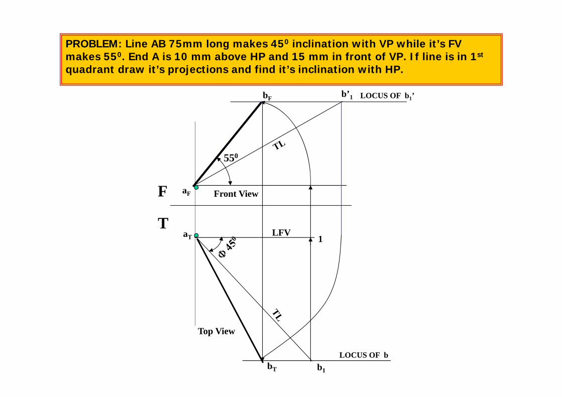
PROBLEM: Line AB 75mm long makes 450 inclination with VP while it’s FV makes 550. End A is 10 mm above HP and 15 mm in front of VP. If line is in 1st
quadrant draw it’s projections and find it’s inclination with HP.
LOCUS OF b
LOCUS OF b1’
FT
a b d c
1 2 4 3
a’
b’
c’
d’
1’
2’
3’
4’
450
4’
3’
2’
1’
d’
c’
b’
a’
350
a1
b1
c1d1
1
2
3
4
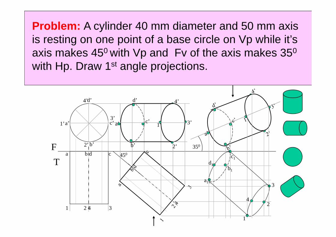
Problem: A cylinder 40 mm diameter and 50 mm axis is resting on one point of a base circle on Vp while it’s axis makes 450 with Vp and Fv of the axis makes 350
with Hp. Draw 1st angle projections.
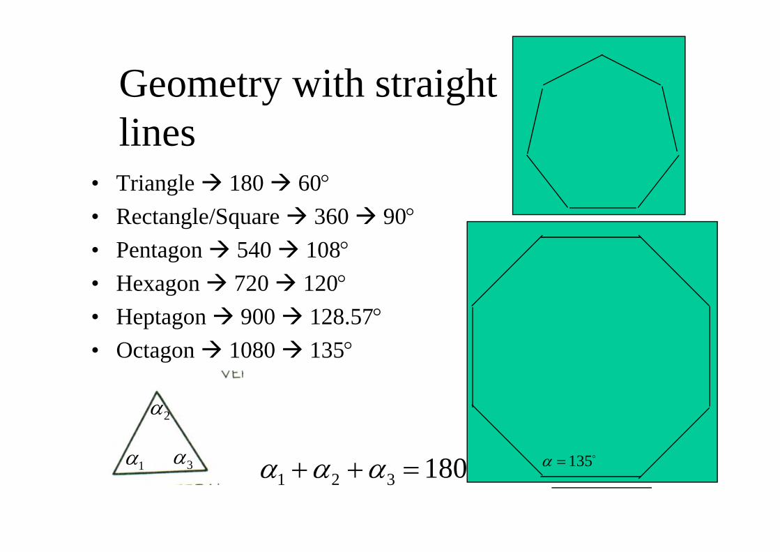
Geometry with straight lines
• Triangle 180 60°• Rectangle/Square 360 90°• Pentagon 540 108°• Hexagon 720 120°• Heptagon 900 128.57°• Octagon 1080 135°
180321 =++ ααα1α
2α
3α o135=α
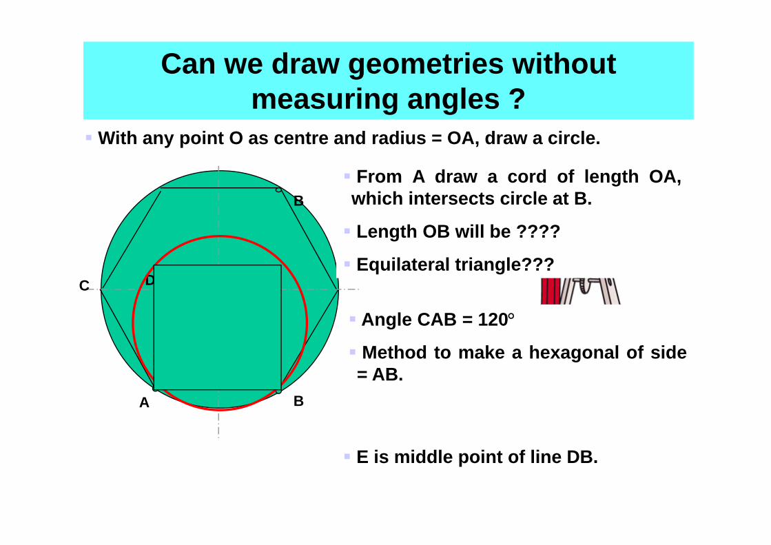
With any point O as centre and radius = OA, draw a circle.
Can we draw geometries without measuring angles ?
O
A B
From A draw a cord of length OA,which intersects circle at B.
Length OB will be ????
Equilateral triangle???C
Angle CAB = 120°
Method to make a hexagonal of side= AB.
D
E
E is middle point of line DB.
B
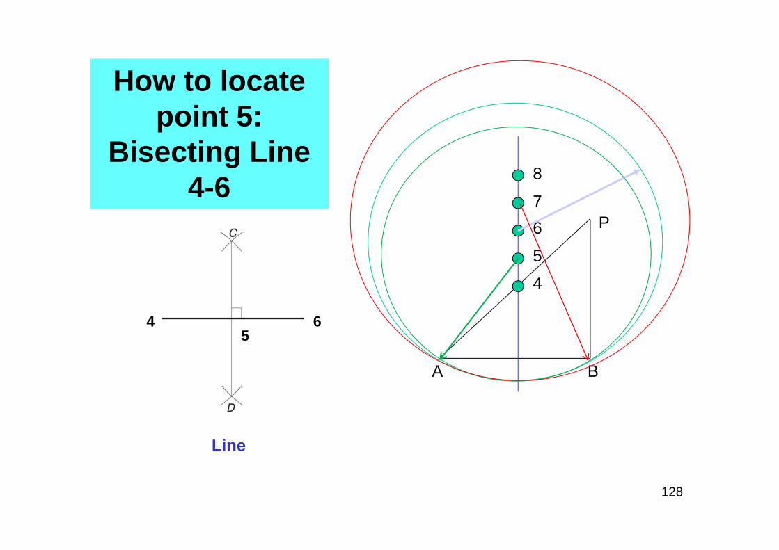
How to locate point 5:
Bisecting Line 4-6
Line
128
E4 65
A
4
6 P
B
5
7
8
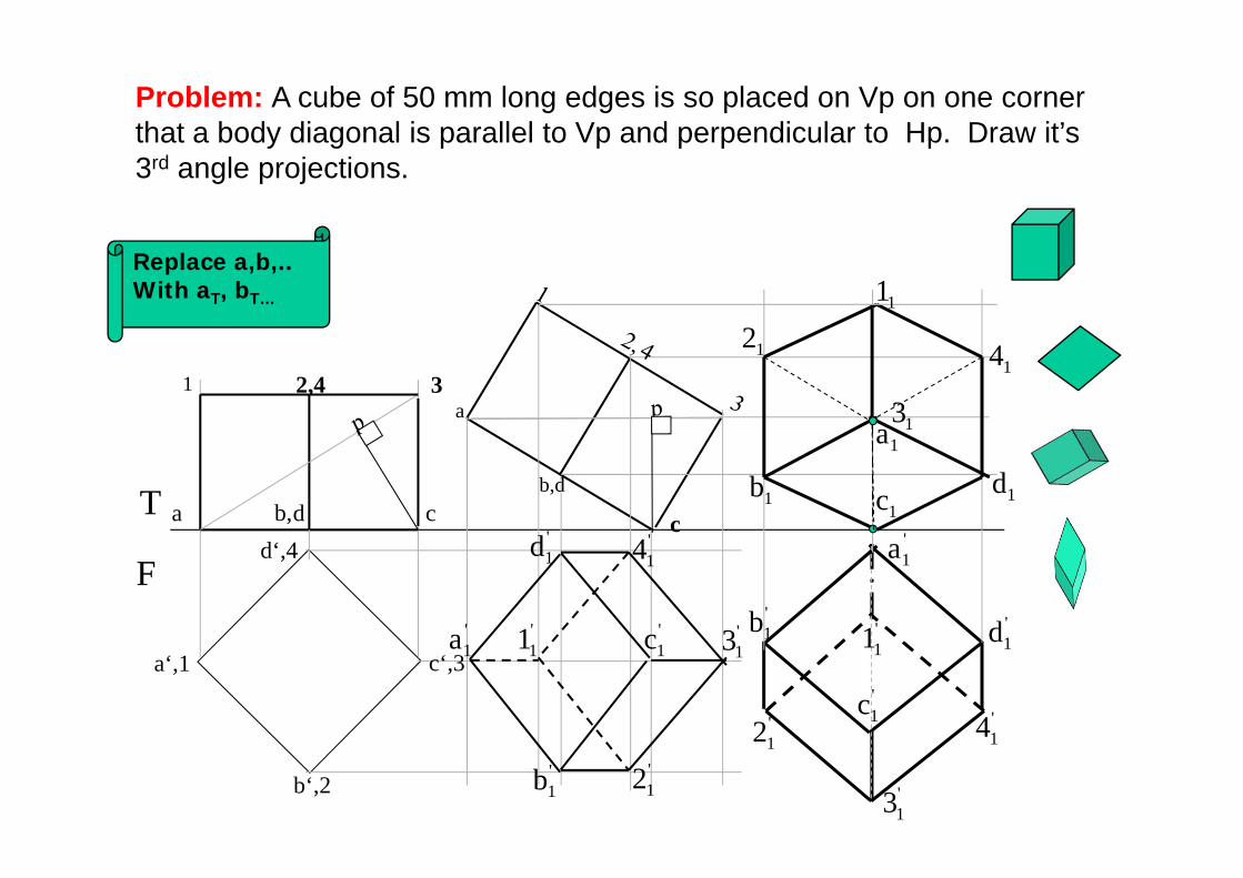
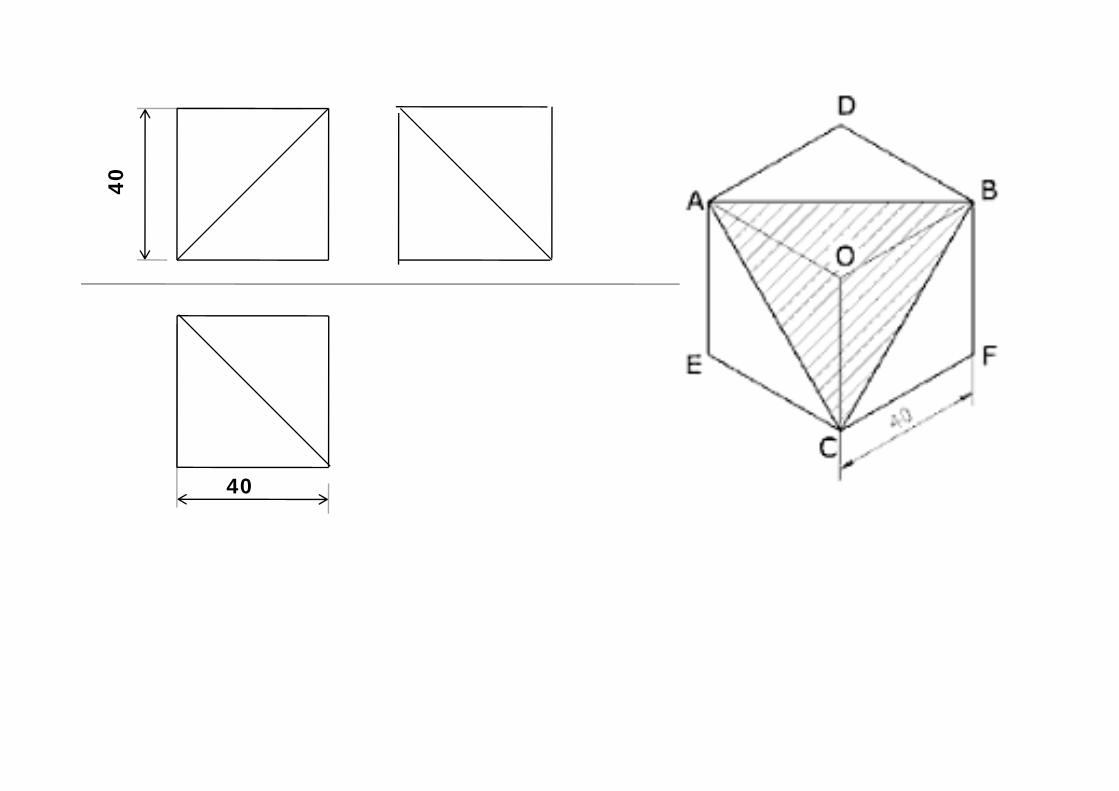
Problem: A cube of 50 mm long edges is so placed on Vp on one corner that a body diagonal is parallel to Vp and perpendicular to Hp. Draw it’s 3rd angle projections.
T
F
b‘,2
c‘,3
d‘,4
a‘,1
a d cb,
31
c
a
b,d
'1a
'1b
'1c
'1d
'11 '
13
'12
'14
2,4
'11
'1a
'13
'1c '
14
'1d
'12
'1b
1c1b 1d1a
11
1214
13
Replace a,b,.. With aT, bT…
b
b1
FT
a
d
co
d’ c’b’a’
o’
c1a1
d1
o1
o’1
a’1b’1c’1
d’1
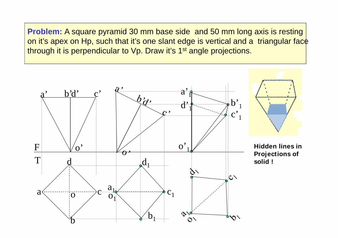
Problem: A square pyramid 30 mm base side and 50 mm long axis is resting on it’s apex on Hp, such that it’s one slant edge is vertical and a triangular face through it is perpendicular to Vp. Draw it’s 1st angle projections.
b
Hidden lines in Projections of solid !
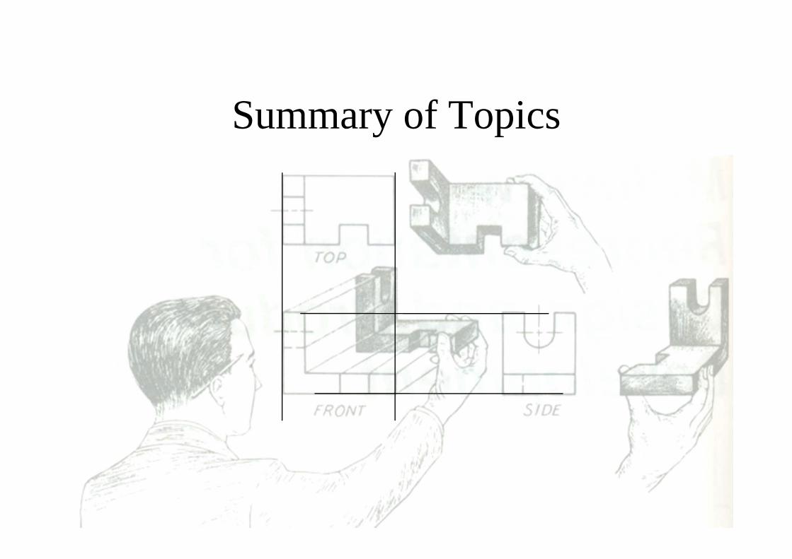
Summary of Topics
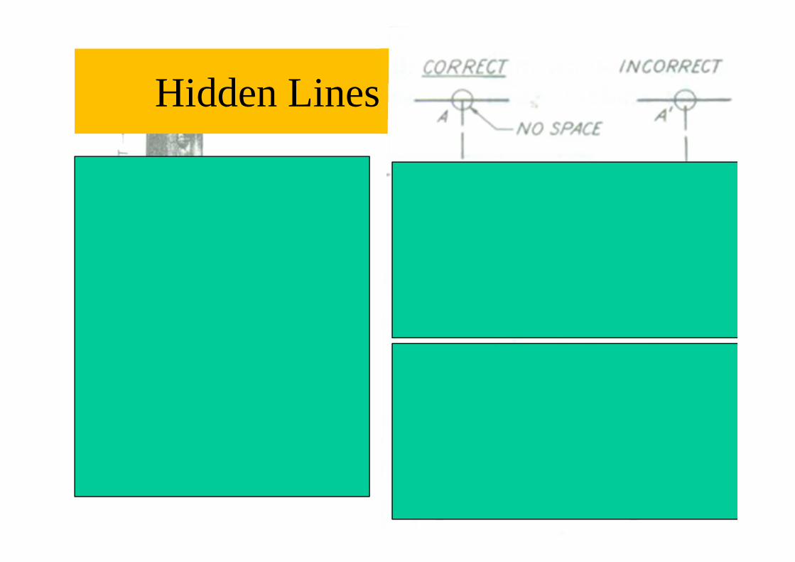
Hidden Lines
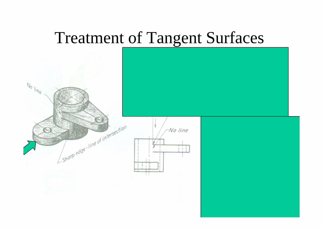
Treatment of Tangent Surfaces
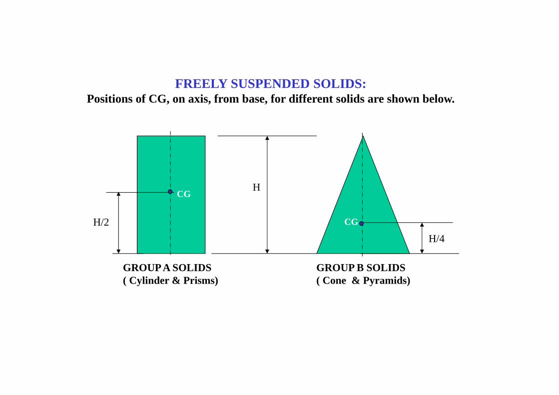
FREELY SUSPENDED SOLIDS:Positions of CG, on axis, from base, for different solids are shown below.
H
H/2H/4
GROUP A SOLIDS( Cylinder & Prisms)
GROUP B SOLIDS( Cone & Pyramids)
CG
CG
T
Fa’ d’e’c’b’
o’
a
b
c
d
e
o
g’H/4
H
LINE d’g’ VERTICAL
a’b’
c’
d’
e’
g’
a1
b1
o1
e1
d1
c1
FOR SIDE VIEW
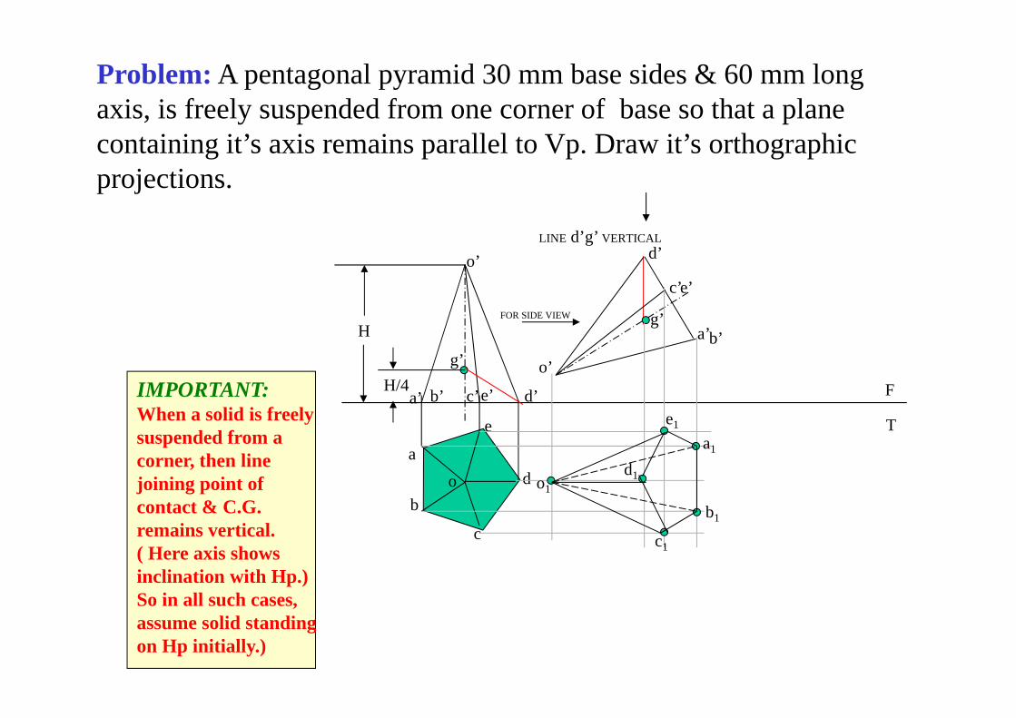
Problem: A pentagonal pyramid 30 mm base sides & 60 mm long axis, is freely suspended from one corner of base so that a plane containing it’s axis remains parallel to Vp. Draw it’s orthographic projections.
IMPORTANT:When a solid is freelysuspended from acorner, then line joining point of contact & C.G. remains vertical.( Here axis shows inclination with Hp.)So in all such cases, assume solid standing on Hp initially.)
o’
O
O
F.V. and S.V.of an object are given. Draw it’s isometric view.
YX
F.V. LEFT S.V.
3020 2010
15
15
15
3050
10
15 O
ORTHOGRAPHIC PROJECTIONS
F. V.
T. V.
L.H.S.
x y
20
20
20
50
20 20 20
20
30
O
O
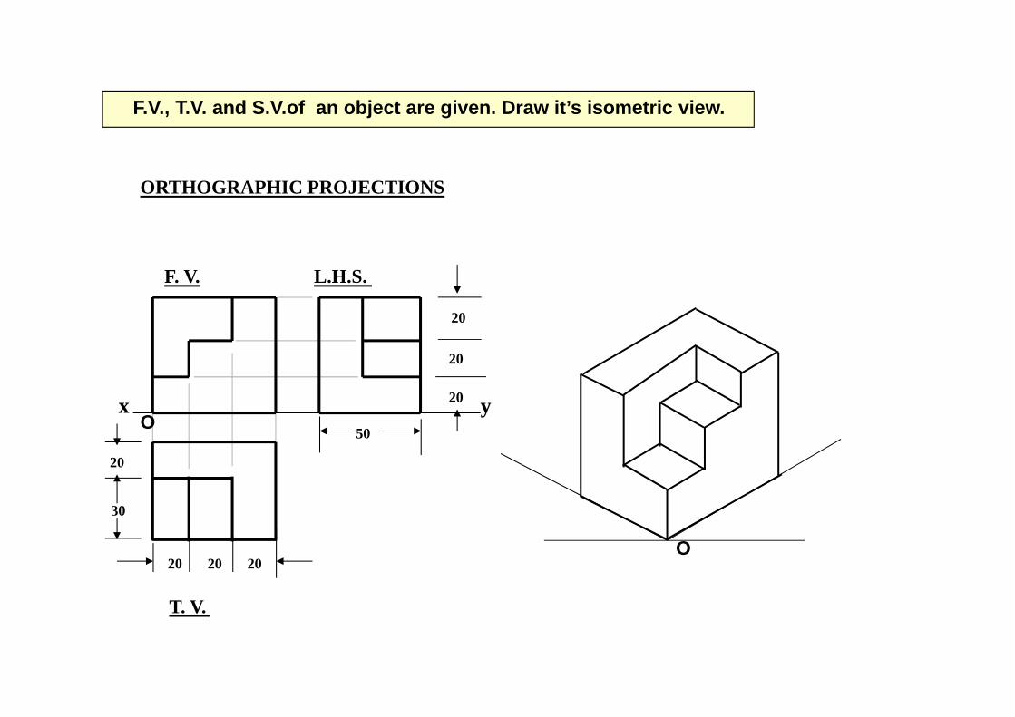
F.V., T.V. and S.V.of an object are given. Draw it’s isometric view.
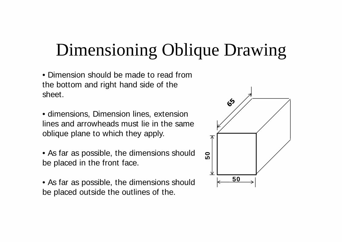
Dimensioning Oblique Drawing
50
50
• Dimension should be made to read from the bottom and right hand side of the sheet.
• dimensions, Dimension lines, extension lines and arrowheads must lie in the same oblique plane to which they apply.
• As far as possible, the dimensions should be placed in the front face.
• As far as possible, the dimensions should be placed outside the outlines of the.