Embed Size (px)
Citation preview
© 2014 Eaton. All Rights Reserved..
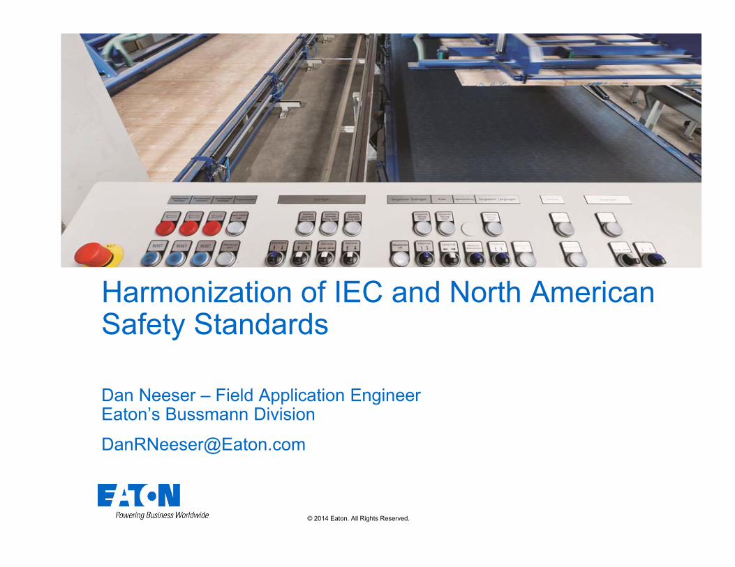
Harmonization of IEC and North American Safety Standards
Dan Neeser – Field Application EngineerEaton’s Bussmann Division
Equipment SCCR made easy
2© 2014 Eaton. All Rights Reserved..
Agenda
• UL 508C, UL 61800-5-1 and transition
• UL 508C & 61800-5-1 differences
• NEC Requirements
• Branch Circuit Protection Device Options

3© 2014 Eaton. All Rights Reserved..
UL 508 Series
• UL• Industrial Control Panels
• UL 508A SUPPLEMENT SB - SHORT CIRCUIT CURRENT RATINGS FOR INDUSTRIAL CONTROL PANELS
• Drives & Power Conversion Equipment
• UL 508C now transitioning to UL 61800-5-1 (harmonize with IEC) –adds requirements for testing ALL outputs and specific requirements for break-down of components test.
• Control Components
• UL 508 now transitioning to UL 60947-1 (harmonize with IEC), no major changes
4© 2014 Eaton. All Rights Reserved..
UL 508C
• UL Standard for Safety for Power Conversion Equipment, UL 508C• Open or enclosed equipment that supplies power to
control a motor or motors operating at a frequency or voltage different than that of the input supply.
• Power-supply modules, input/output modules, Silicon Controlled Rectifier (SCR) or Transistor output modules, dynamic braking units, and input/output accessory kits for use with power conversion equipment.
• 1500 volts or less.
5© 2014 Eaton. All Rights Reserved..
UL 61800-5-1
• Harmonizes the IEC 61800-5-1 with UL 508C standards, with National Differences as noted in the Standard.
• National Differences can be based on• National regulatory requirements (DR)• Basic safety principals and requirements (D1)• Safety practices (D2)• Component standard (DC)• Editorial comments/corrections (DE)• They can add, modify or delete requirements.
6© 2014 Eaton. All Rights Reserved..
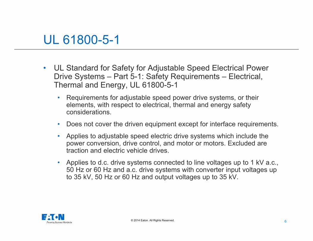
UL 61800-5-1
• UL Standard for Safety for Adjustable Speed Electrical Power Drive Systems – Part 5-1: Safety Requirements – Electrical, Thermal and Energy, UL 61800-5-1• Requirements for adjustable speed power drive systems, or their
elements, with respect to electrical, thermal and energy safety considerations.
• Does not cover the driven equipment except for interface requirements.
• Applies to adjustable speed electric drive systems which include the power conversion, drive control, and motor or motors. Excluded are traction and electric vehicle drives.
• Applies to d.c. drive systems connected to line voltages up to 1 kV a.c., 50 Hz or 60 Hz and a.c. drive systems with converter input voltages up to 35 kV, 50 Hz or 60 Hz and output voltages up to 35 kV.

7© 2014 Eaton. All Rights Reserved..
UL 61800-5-1 Deviations
• UL Standard for Safety for Adjustable Speed Electrical Power Drive Systems – Part 5-1: Safety Requirements – Electrical, Thermal and Energy, UL 61800-5-1• DV.1.1 This document is only applicable to the power
conversion and drive control equipment, servo drives and integral servo drive/motor combinations.
• DV.1.2 Only devices connected to line voltages of up to 1,5 kV a.c. are covered.
• DV.1.3 A component of a product covered by this standard shall comply with the requirements for that component. See Annex DVA for a list of additional standards covering components used in the products covered by this standard.

8© 2014 Eaton. All Rights Reserved..
UL 61800-5-1 & Transition Timeline
• First edition published June 2012.
• Current revision March 2015.
• All new (series or models for existing series) power-conversion products required to be investigated to UL 61800-5-1 February 2016.
• UL 508C is withdrawn – all products required to be evaluated to UL 61800-5-1 February 2020.

9© 2014 Eaton. All Rights Reserved..
Benefits
• Harmonization of IEC and North American Safety Standards that brings the standards closer together.
• Moving toward one standard for adjustable speed drives for IEC or NA applications.
10© 2014 Eaton. All Rights Reserved..
Design Implications
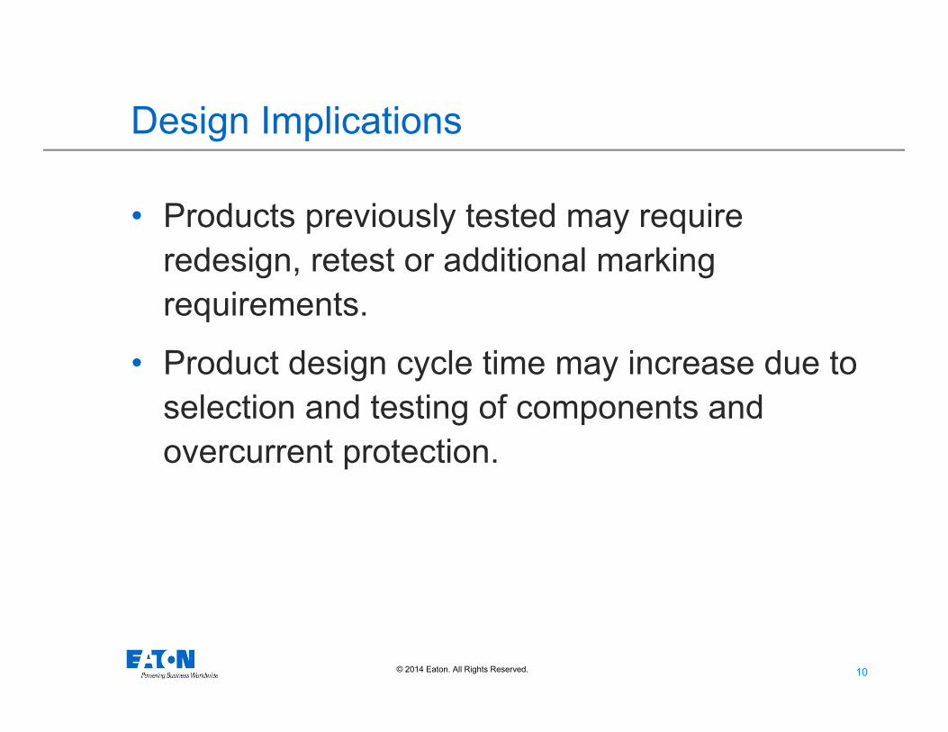
• Products previously tested may require redesign, retest or additional marking requirements.
• Product design cycle time may increase due to selection and testing of components and overcurrent protection.

11© 2014 Eaton. All Rights Reserved..
Differences of UL 508C vs 61800-5-1
• Requirements for creepage and clearance distances and methods of reducing clearances have been revised.
• Short-circuit testing of all power outputs (not just main power output) is required.
• Specific requirements and changes to the procedure for the breakdown of components standard and high fault current test have been added.
• Protective bonding test now required for products with accessible conductive parts.

12© 2014 Eaton. All Rights Reserved..
UL 508C UL 61800Only required the motor output to be short circuit tested
All outputs must be short-circuit tested
No specific requirements for the short-circuit testing of internal components (breakdown of components testing).
Internal components must be tested for standard and high fault currents based onmanufacturer’s short circuit current rating; unless analysis shows a different value is more severe.
Testing with cotton not required during short circuit and breakdown of components testing with circuit breakers.
Cotton indicator is required for all short circuit and breakdown of components tests when testing with circuit breakers.
Monitoring of secondary circuit voltage during short-circuit and break down of components test not required as part of pass/fail criteria.
Secondary circuit voltages are required to be monitored and not exceed specified levels during the short circuit and breakdown of components tests, or the AC/DC voltage test must be conducted after the short circuit test and breakdown of component test.
Differences of UL 508C vs 61800-5-1
13© 2014 Eaton. All Rights Reserved..
Additional Challenges
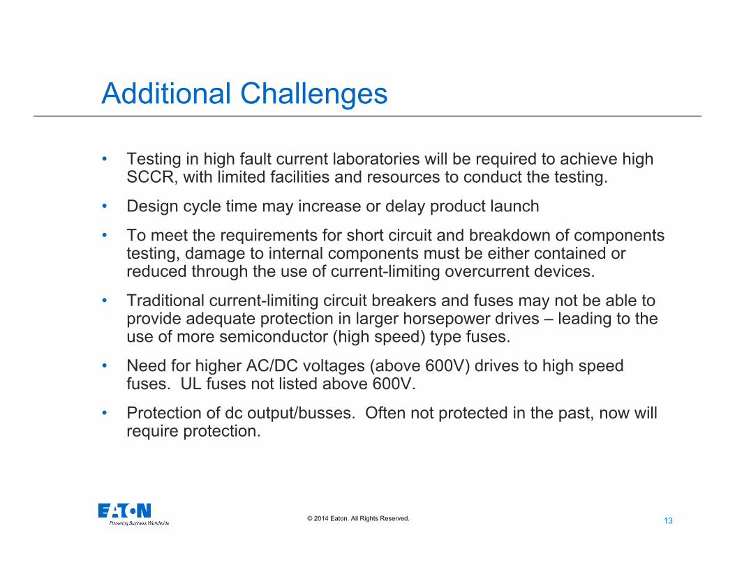
• Testing in high fault current laboratories will be required to achieve high SCCR, with limited facilities and resources to conduct the testing.
• Design cycle time may increase or delay product launch
• To meet the requirements for short circuit and breakdown of components testing, damage to internal components must be either contained or reduced through the use of current-limiting overcurrent devices.
• Traditional current-limiting circuit breakers and fuses may not be able to provide adequate protection in larger horsepower drives – leading to the use of more semiconductor (high speed) type fuses.
• Need for higher AC/DC voltages (above 600V) drives to high speed fuses. UL fuses not listed above 600V.
• Protection of dc output/busses. Often not protected in the past, now will require protection.

14© 2014 Eaton. All Rights Reserved..
NEC Requirements430.130 Branch-Circuit Short-Circuit and Ground-Fault Protection for Single Motor Circuits Containing Power Conversion Equipment.
(A) Circuits Containing Power Conversion Equipment.
Circuits containing power conversion equipment shall be protected by a branch-circuit short-circuit and ground-fault protective device in accordance with the following:
(1) The rating and type of protection shall be determined by 430.52(C)(1), (C)(3), (C)(5), or (C)(6), using the full-load current rating of the motor load as determined by 430.6.
(2) Where maximum branch-circuit short-circuit and ground-fault protective ratings are stipulated for specific device types in the manufacturer’s instructions for the power conversion equipment or are otherwise marked on the equipment, they shall not be exceeded even if higher values are permitted by 430.130(A)(1).
(3) A self-protected combination controller shall only be permitted where specifically identified in the manufacturer’s instructions for the power conversion equipment or if otherwise marked on the equipment.
15© 2014 Eaton. All Rights Reserved..
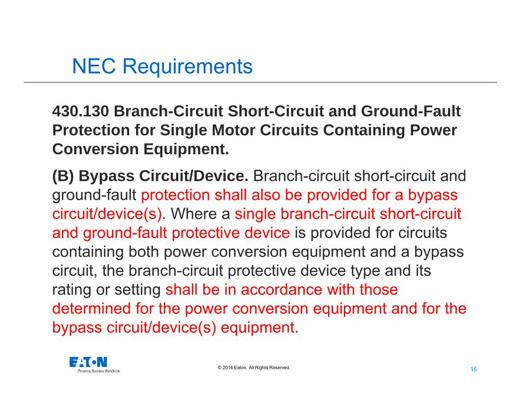
NEC Requirements
430.130 Branch-Circuit Short-Circuit and Ground-Fault Protection for Single Motor Circuits Containing Power Conversion Equipment.(B) Bypass Circuit/Device. Branch-circuit short-circuit and ground-fault protection shall also be provided for a bypass circuit/device(s). Where a single branch-circuit short-circuit and ground-fault protective device is provided for circuits containing both power conversion equipment and a bypass circuit, the branch-circuit protective device type and its rating or setting shall be in accordance with those determined for the power conversion equipment and for the bypass circuit/device(s) equipment.
16© 2014 Eaton. All Rights Reserved..
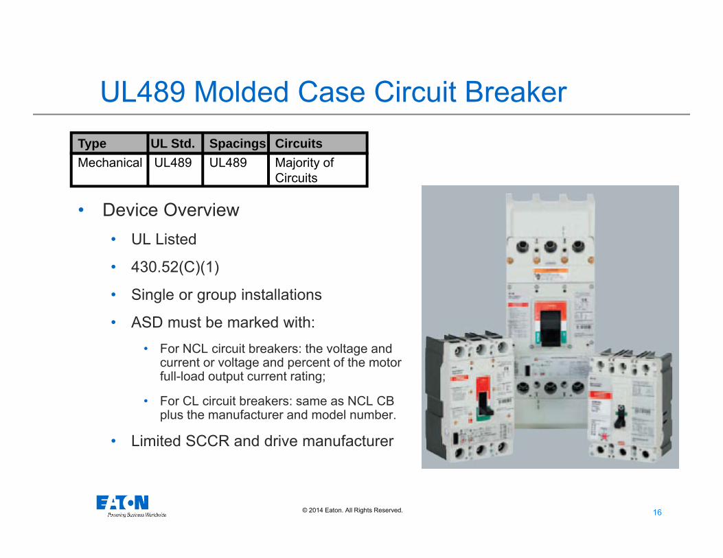
UL489 Molded Case Circuit Breaker
• Device Overview• UL Listed
• 430.52(C)(1)
• Single or group installations
• ASD must be marked with:• For NCL circuit breakers: the voltage and
current or voltage and percent of the motor full-load output current rating;
• For CL circuit breakers: same as NCL CB plus the manufacturer and model number.
• Limited SCCR and drive manufacturer
Type UL Std. Spacings CircuitsMechanical UL489 UL489 Majority of
Circuits
17© 2014 Eaton. All Rights Reserved..
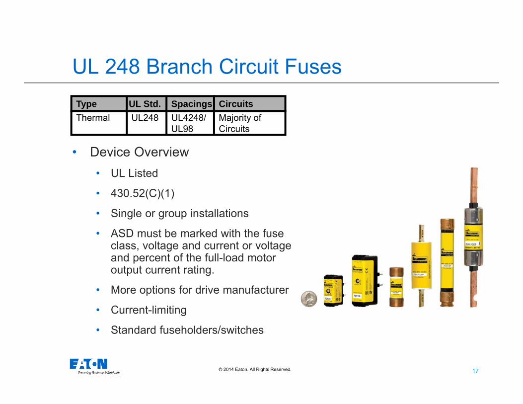
UL 248 Branch Circuit Fuses
• Device Overview• UL Listed
• 430.52(C)(1)
• Single or group installations
• ASD must be marked with the fuse class, voltage and current or voltage and percent of the full-load motor output current rating.
• More options for drive manufacturer
• Current-limiting
• Standard fuseholders/switches
Type UL Std. Spacings CircuitsThermal UL248 UL4248/ Majority of
UL98 Circuits

18© 2014 Eaton. All Rights Reserved..
Instantaneous Trip CB (MCP)
• Device Overview
• UL Recognized
• 430.52(C)(3)
• Single ASD applications
• Must be marked with manufacturer and model number and integrated into the overall assembly
• Limits options for drive manufacturers
Type UL Std. Spacings Circuits
Mechanical UL489 UL489 Motor

19© 2014 Eaton. All Rights Reserved..
Semiconductor (High Speed) FusesType UL Std. Spacings CircuitsThermal UL248 UL4248 Power Electronic
Devices
• Device Overview
• UL Recognized
• 430.52(C)(5)
• Single ASD applications
• Must be marked with manufacturer and model number and integrated into the overall assembly
• Increased current-limitation
• Less options for holders/switches
20© 2014 Eaton. All Rights Reserved..
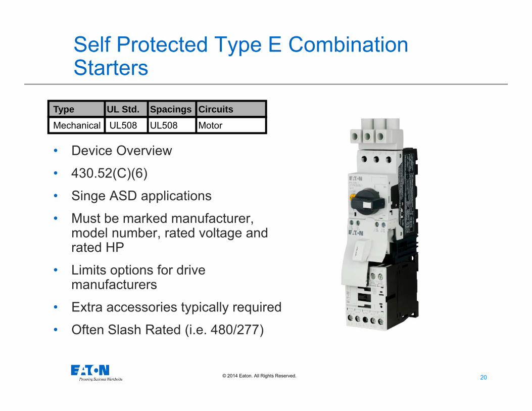
Self Protected Type E Combination Starters
• Device Overview
• 430.52(C)(6)
• Singe ASD applications
• Must be marked manufacturer, model number, rated voltage and rated HP
• Limits options for drive manufacturers
• Extra accessories typically required
• Often Slash Rated (i.e. 480/277)
Type UL Std. Spacings CircuitsMechanical UL508 UL508 Motor
21© 2014 Eaton. All Rights Reserved..
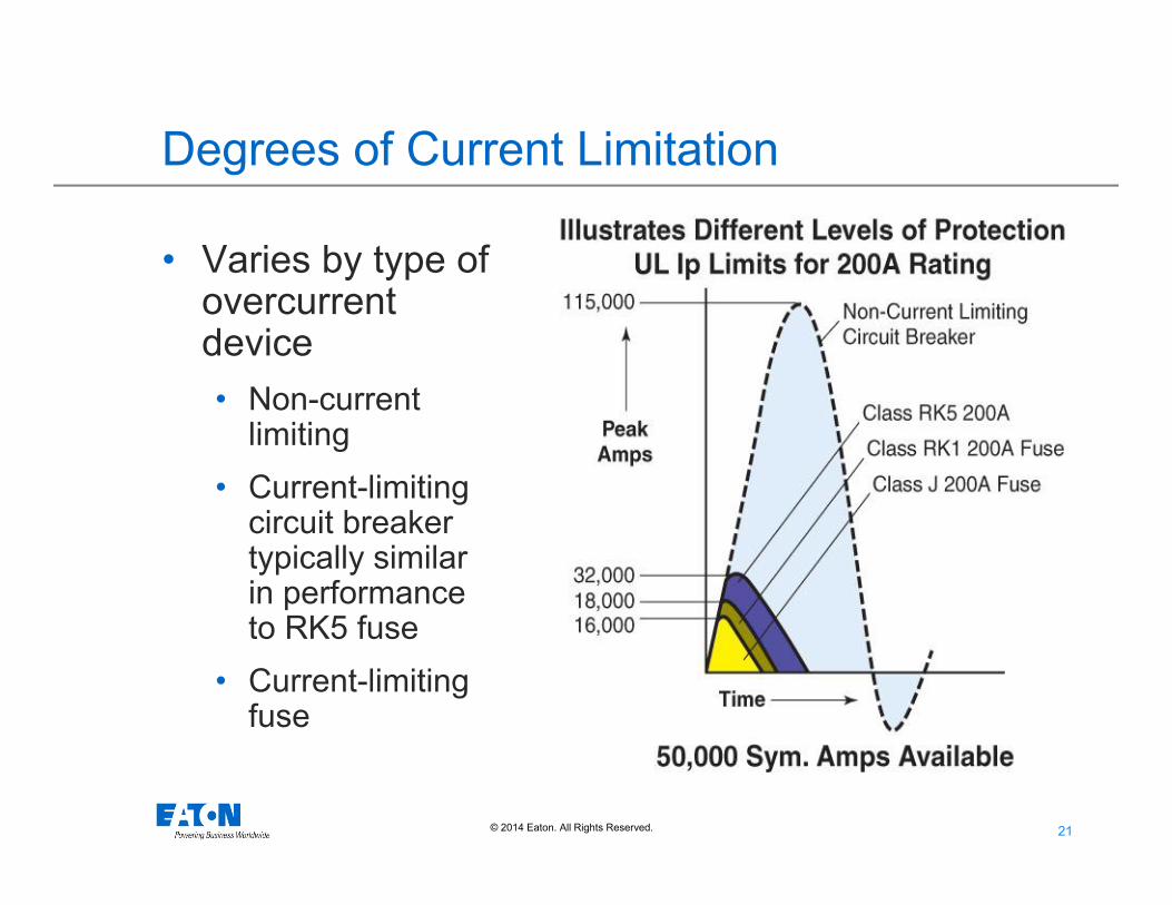
Degrees of Current Limitation
• Varies by type of overcurrent device• Non-current
limiting• Current-limiting
circuit breaker typically similar in performance to RK5 fuse
• Current-limiting fuse

22© 2014 Eaton. All Rights Reserved..
Class L
• “Large”
• Class L – Low-Peak® • KRP-C-(AMP)SP
• 600V, 601A – 6000A, 300kA
• Characteristics• Time Delay
• Current limiting
• The large the ampacity, the more fault current needed to be current-limiting.
23© 2014 Eaton. All Rights Reserved..
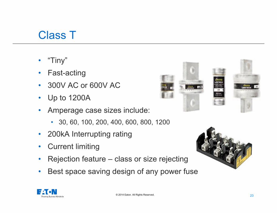
Class T
• “Tiny”• Fast-acting• 300V AC or 600V AC• Up to 1200A• Amperage case sizes include:
• 30, 60, 100, 200, 400, 600, 800, 1200
• 200kA Interrupting rating• Current limiting• Rejection feature – class or size rejecting• Best space saving design of any power fuse
24© 2014 Eaton. All Rights Reserved..
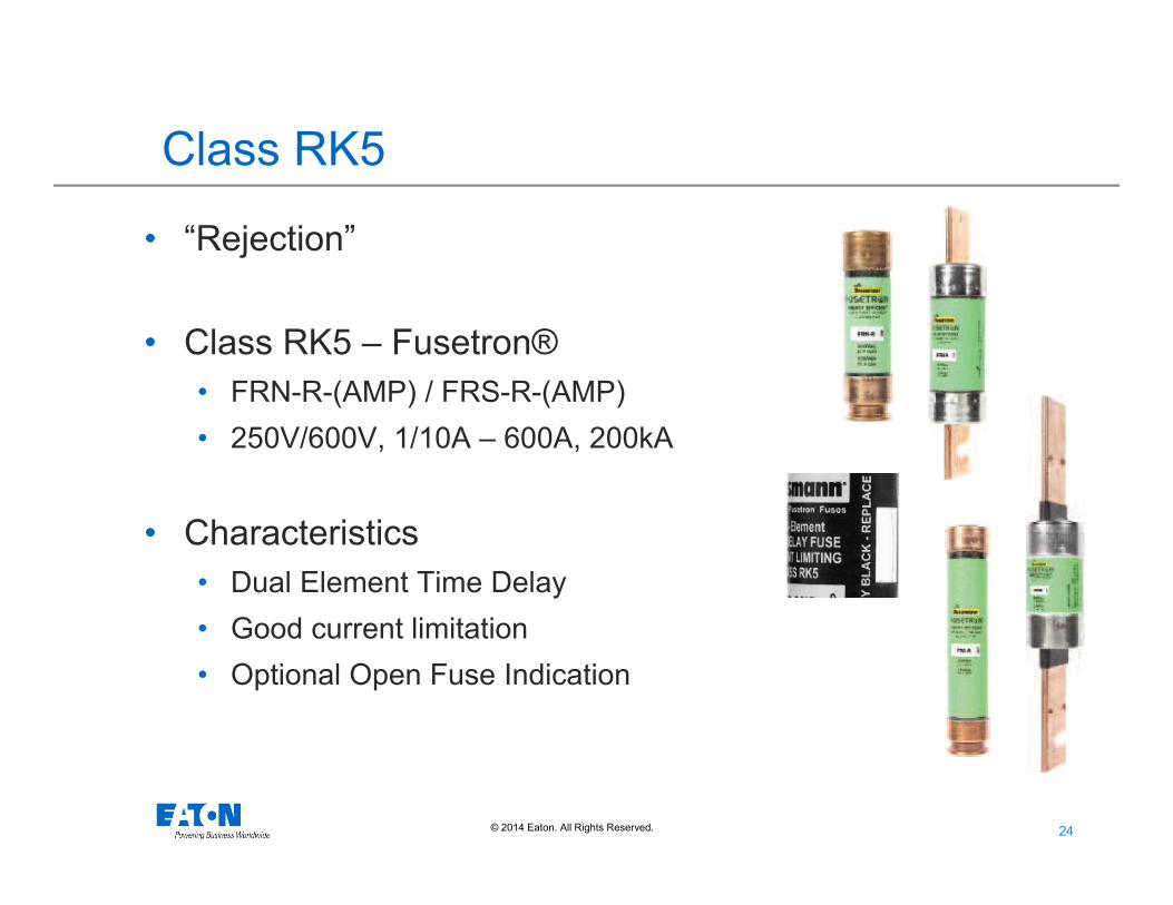
Class RK5
• “Rejection”
• Class RK5 – Fusetron® • FRN-R-(AMP) / FRS-R-(AMP)• 250V/600V, 1/10A – 600A, 200kA
• Characteristics• Dual Element Time Delay• Good current limitation • Optional Open Fuse Indication
25© 2014 Eaton. All Rights Reserved..
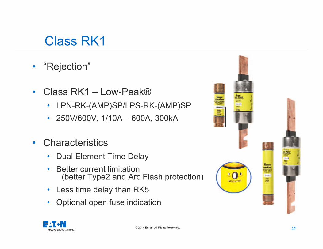
Class RK1
• “Rejection”
• Class RK1 – Low-Peak® • LPN-RK-(AMP)SP/LPS-RK-(AMP)SP• 250V/600V, 1/10A – 600A, 300kA
• Characteristics• Dual Element Time Delay• Better current limitation
(better Type2 and Arc Flash protection)• Less time delay than RK5• Optional open fuse indication

26© 2014 Eaton. All Rights Reserved..
Class J• “Junior”
• Class J – Low-Peak® • LPJ-(AMP)SP• 600V, 1A – 600A, 300kA
• Characteristics• Dual Element Time Delay
• Better time delay than CC• Less time delay than RK1/RK5
• Very current limiting• Smaller than RK1/RK5• Open fuse indication Optional• Finger-safe accessories

27© 2014 Eaton. All Rights Reserved..
Class J – Drive Fuse (DFJ)• “Junior”
• Class J – DFJ High Speed Fuse• DFJ-(AMP)• 600V, 1A – 600A, 200kA• 450Vdc, 100kA
• Characteristics• High speed performance: extremely current limiting
(similar to high speed fuses)• 5X or more current-limiting than traditional time-delay
Class J fuses

28© 2014 Eaton. All Rights Reserved..
Class CF
• “CUBE FUSE”
• Class CF - TCF(amp), TCF(amp)RN or FCF(amp)RN• TCF - 600Vac/300Vdc, 1-100A, 300kA/100kA• FCF - 600Vac/dc, 1-100A 200kA/50kA
• Characteristics• DE Time Delay or Fast Acting• Class J Performance• Very Current Limiting• Small physical Size• Finger safe IP20• Optional Indicating version time-delay only

29© 2014 Eaton. All Rights Reserved..
Class CC
• “Control Circuit” or “Charlie Chaplin” (little hat)
• Class CC - General Features• 600V, up to 30A• 200kA Interrupting rating• Very Current Limiting• Space Saving Design - 13/32” X 1½”
• Grooved ferrule provides rejection feature from supplementary fuses with same dimensions (midget fuses) when Class CC fuseholders are used
• Offer 3 different fuse types • Time delay (for motor circuit: LP-CC)• Time delay (for control transformer primary: FNQ-R)• Non-time delay (Non-inductive loads: KTK-R)
30© 2014 Eaton. All Rights Reserved..
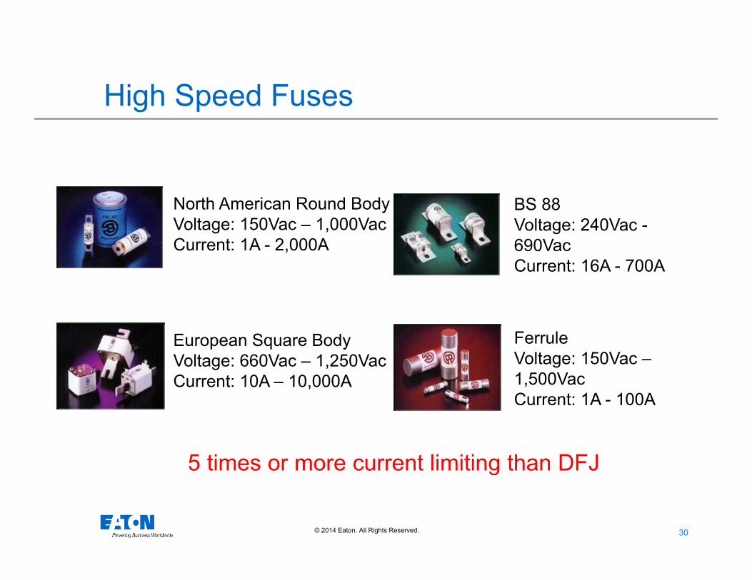
High Speed Fuses
North American Round BodyVoltage: 150Vac – 1,000VacCurrent: 1A - 2,000A
European Square BodyVoltage: 660Vac – 1,250VacCurrent: 10A – 10,000A
BS 88 Voltage: 240Vac -690VacCurrent: 16A - 700A
FerruleVoltage: 150Vac –1,500VacCurrent: 1A - 100A
5 times or more current limiting than DFJ
31© 2014 Eaton. All Rights Reserved..
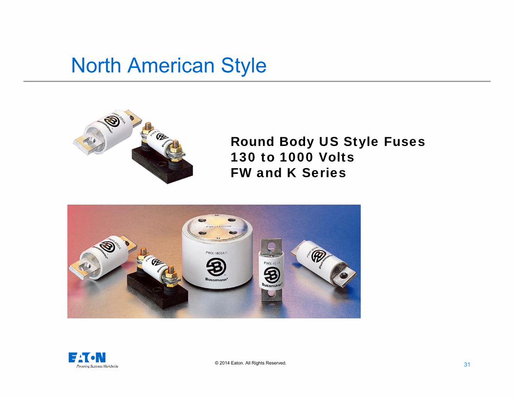
Round Body US Style Fuses130 to 1000 VoltsFW and K Series
North American Style
32© 2014 Eaton. All Rights Reserved..
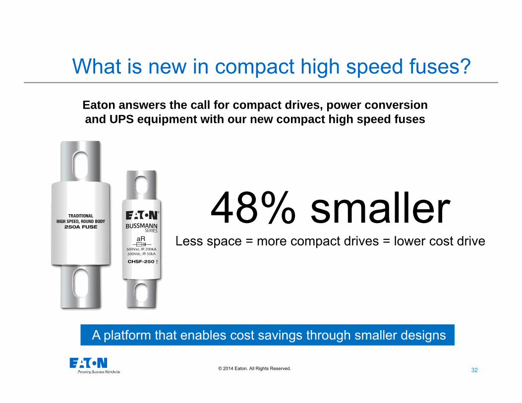
What is new in compact high speed fuses?
Eaton answers the call for compact drives, power conversion and UPS equipment with our new compact high speed fuses
48% smallerLess space = more compact drives = lower cost drive
A platform that enables cost savings through smaller designs
33© 2014 Eaton. All Rights Reserved..
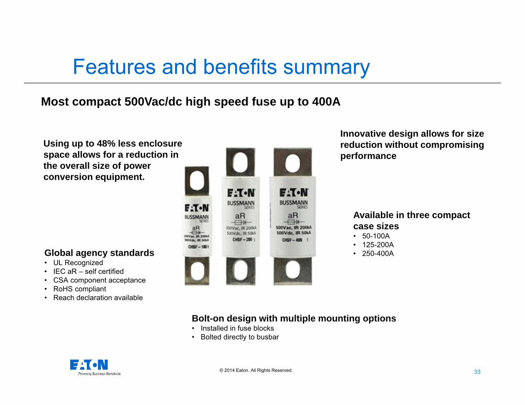
Features and benefits summary
Bolt-on design with multiple mounting options• Installed in fuse blocks• Bolted directly to busbar
Most compact 500Vac/dc high speed fuse up to 400A
Innovative design allows for size reduction without compromising performance
Global agency standards• UL Recognized• IEC aR – self certified• CSA component acceptance• RoHS compliant• Reach declaration available
Using up to 48% less enclosure space allows for a reduction in the overall size of power conversion equipment.
Available in three compact case sizes• 50-100A• 125-200A• 250-400A
34© 2014 Eaton. All Rights Reserved..
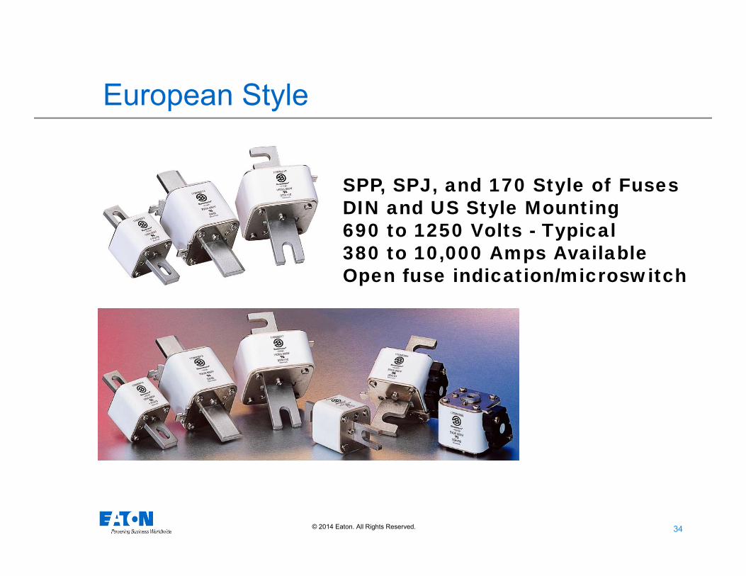
SPP, SPJ, and 170 Style of FusesDIN and US Style Mounting690 to 1250 Volts - Typical380 to 10,000 Amps AvailableOpen fuse indication/microswitch
European Style

35© 2014 Eaton. All Rights Reserved..
BS 88 Style240 to 690 Volts
British Style

36© 2014 Eaton. All Rights Reserved..
Ferrule Style6x32mm (1/4 x 1-1/4)10x38mm (13/32 x 1-1/2)14x51mm (9/16 x 2)22x58mm 20x127mm
Ferrule Style

37© 2014 Eaton. All Rights Reserved..
Selecting HSF’s
• Basic Process:• Determine duty cycle of load current (Irms)
based on configuration and placement of fuse protection
• Select fuse (type, terminations, etc)• Determine required ampacity of fuse (In)• Analyze overload and pulse (such as inrush)
characteristics with fuse selected• Analyze protection level of device
38© 2014 Eaton. All Rights Reserved..
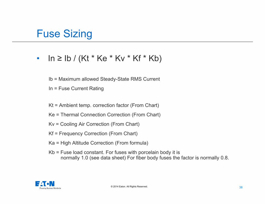
Fuse Sizing
• In ≥ Ib / (Kt * Ke * Kv * Kf * Kb)
Ib = Maximum allowed Steady-State RMS Current
In = Fuse Current Rating
Kt = Ambient temp. correction factor (From Chart)
Ke = Thermal Connection Correction (From Chart)
Kv = Cooling Air Correction (From Chart)
Kf = Frequency Correction (From Chart)
Ka = High Altitude Correction (From formula)
Kb = Fuse load constant. For fuses with porcelain body it is normally 1.0 (see data sheet) For fiber body fuses the factor is normally 0.8.
39© 2014 Eaton. All Rights Reserved..
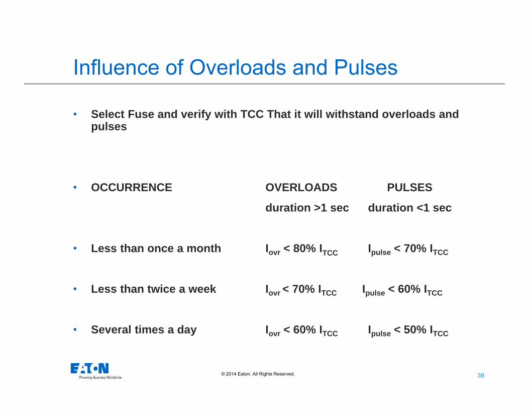
• Select Fuse and verify with TCC That it will withstand overloads and pulses
• OCCURRENCE OVERLOADS PULSES
duration >1 sec duration <1 sec
• Less than once a month Iovr < 80% ITCC Ipulse < 70% ITCC
• Less than twice a week Iovr < 70% ITCC Ipulse < 60% ITCC
• Several times a day Iovr < 60% ITCC Ipulse < 50% ITCC
Influence of Overloads and Pulses
40© 2014 Eaton. All Rights Reserved..
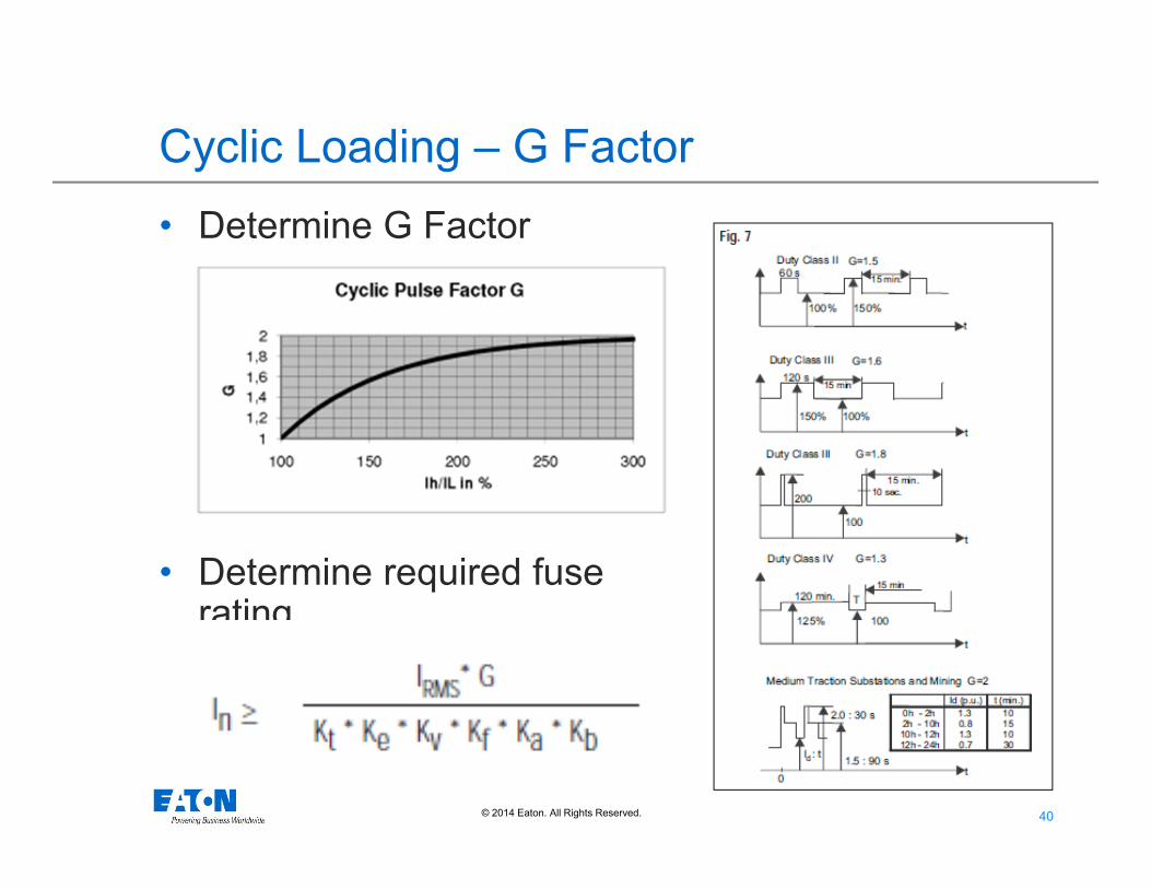
Cyclic Loading – G Factor• Determine G Factor
• Determine required fuse rating
41© 2014 Eaton. All Rights Reserved..
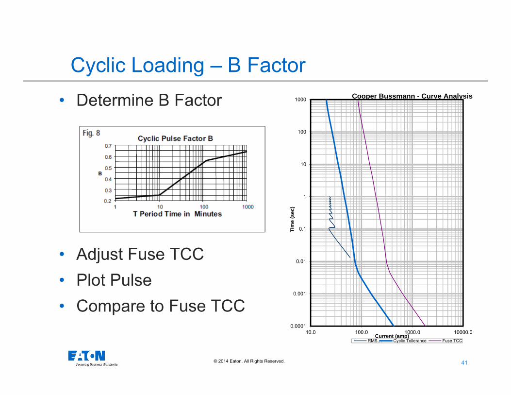
Cyclic Loading – B Factor• Determine B Factor
• Adjust Fuse TCC• Plot Pulse• Compare to Fuse TCC
0.0001
0.001
0.01
0.1
1
10
100
1000
10.0 100.0 1000.0 10000.0
Tim
e (s
ec)
Current (amp)
Cooper Bussmann - Curve Analysis
RMS… Cyclic Tollerance Fuse TCC

42© 2014 Eaton. All Rights Reserved..
Critical Data for High Speed Fuses
I2t Derating
Fuse operating on a 480V System will allow the clearing I2t to drop 30%

43© 2014 Eaton. All Rights Reserved..
Critical Data for High Speed Fuses
Arc Voltage Watts Loss
44© 2014 Eaton. All Rights Reserved..
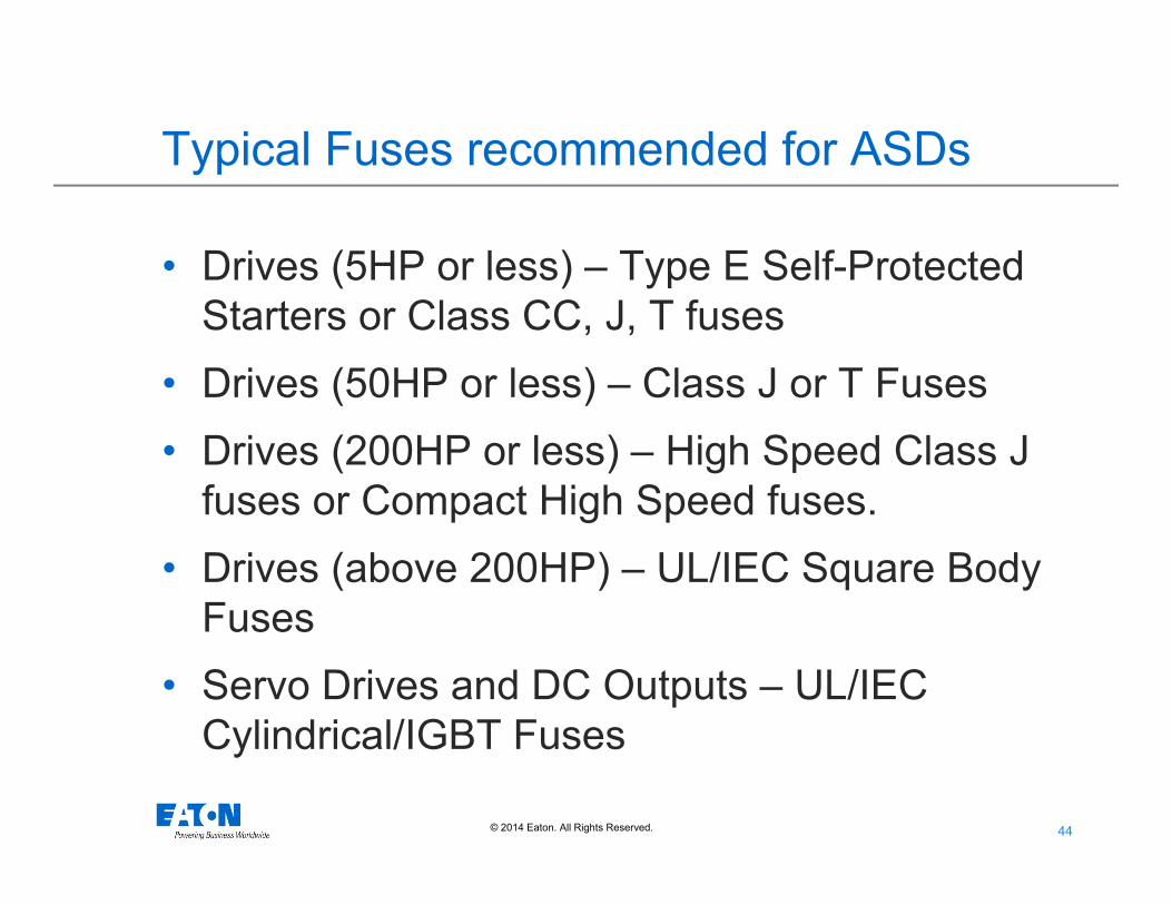
Typical Fuses recommended for ASDs
• Drives (5HP or less) – Type E Self-Protected Starters or Class CC, J, T fuses
• Drives (50HP or less) – Class J or T Fuses• Drives (200HP or less) – High Speed Class J
fuses or Compact High Speed fuses.• Drives (above 200HP) – UL/IEC Square Body
Fuses• Servo Drives and DC Outputs – UL/IEC
Cylindrical/IGBT Fuses
© 2014 Eaton. All Rights Reserved..
Questions?
Dan Neeser
Field Application Engineer