Embed Size (px)
Citation preview
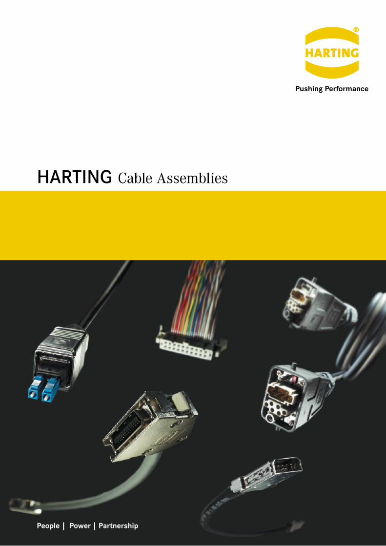
HARTING
People | Power | Partnership
Cable Assemblies

Transforming customer wishes into concrete solutions
The HARTING Technology Group is skilled in the fields of electrical, electronic and optical
connection, transmission and networking, as well as in manufacturing, mechatronics and
software creation. The Group uses these skills to develop customized solutions and products
such as connectors for energy and data transmission applications including, for example,
mechanical engineering, rail technology, wind energy plants, factory automation and the
telecommunications sector. In addition, HARTING also produces electro-magnetic components for
the automobile industry and offers solutions in the field of Enclosures and Shop Systems.
The HARTING Group currently comprises 36 subsidiary companies and worldwide distributors
employing a total of approximately 3,300 staff.
H A R T I N G w o r l d w i d e
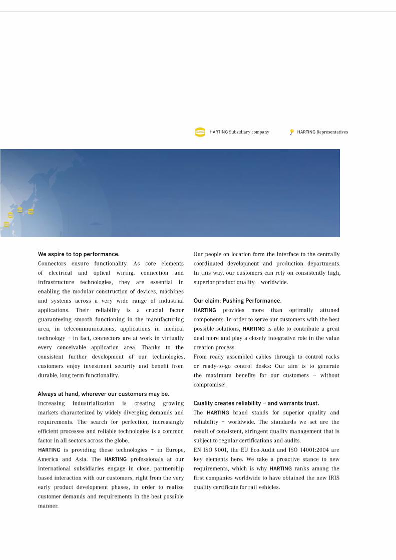
HARTING RepresentativesHARTING Subsidiary company
We aspire to top performance.
Connectors ensure functionality. As core elements
of electrical and optical wiring, connection and
infrastructure technologies, they are essential in
enabling the modular construction of devices, machines
and systems across a very wide range of industrial
applications. Their reliability is a crucial factor
guaranteeing smooth functioning in the manufacturing
area, in telecommunications, applications in medical
technology – in fact, connectors are at work in virtually
every conceivable application area. Thanks to the
consistent further development of our technologies,
customers enjoy investment security and benefit from
durable, long term functionality.
Always at hand, wherever our customers may be.
Increasing industrialization is creating growing
markets characterized by widely diverging demands and
requirements. The search for perfection, increasingly
efficient processes and reliable technologies is a common
factor in all sectors across the globe.
HARTING is providing these technologies – in Europe,
America and Asia. The HARTING professionals at our
international subsidiaries engage in close, partnership
based interaction with our customers, right from the very
early product development phases, in order to realize
customer demands and requirements in the best possible
manner.
Our people on location form the interface to the centrally
coordinated development and production departments.
In this way, our customers can rely on consistently high,
superior product quality – worldwide.
Our claim: Pushing Performance.
HARTING provides more than optimally attuned
components. In order to serve our customers with the best
possible solutions, HARTING is able to contribute a great
deal more and play a closely integrative role in the value
creation process.
From ready assembled cables through to control racks
or ready-to-go control desks: Our aim is to generate
the maximum benefits for our customers – without
compromise!
Quality creates reliability – and warrants trust.
The HARTING brand stands for superior quality and
reliability – worldwide. The standards we set are the
result of consistent, stringent quality management that is
subject to regular certifications and audits.
EN ISO 9001, the EU Eco-Audit and ISO 14001:2004 are
key elements here. We take a proactive stance to new
requirements, which is why HARTING ranks among the
first companies worldwide to have obtained the new IRIS
quality certificate for rail vehicles.
H A R T I N G w o r l d w i d e
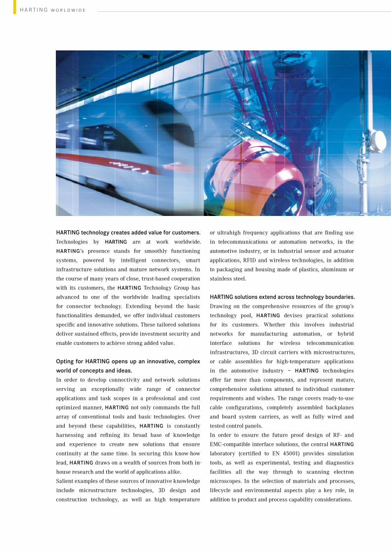
HARTING technology creates added value for customers.
Technologies by HARTING are at work worldwide.
HARTING’s presence stands for smoothly functioning
systems, powered by intelligent connectors, smart
infrastructure solutions and mature network systems. In
the course of many years of close, trust-based cooperation
with its customers, the HARTING Technology Group has
advanced to one of the worldwide leading specialists
for connector technology. Extending beyond the basic
functionalities demanded, we offer individual customers
specific and innovative solutions. These tailored solutions
deliver sustained effects, provide investment security and
enable customers to achieve strong added value.
Opting for HARTING opens up an innovative, complex
world of concepts and ideas.
In order to develop connectivity and network solutions
serving an exceptionally wide range of connector
applications and task scopes in a professional and cost
optimized manner, HARTING not only commands the full
array of conventional tools and basic technologies. Over
and beyond these capabilities, HARTING is constantly
harnessing and refining its broad base of knowledge
and experience to create new solutions that ensure
continuity at the same time. In securing this know-how
lead, HARTING draws on a wealth of sources from both in-
house research and the world of applications alike.
Salient examples of these sources of innovative knowledge
include microstructure technologies, 3D design and
construction technology, as well as high temperature
or ultrahigh frequency applications that are finding use
in telecommunications or automation networks, in the
automotive industry, or in industrial sensor and actuator
applications, RFID and wireless technologies, in addition
to packaging and housing made of plastics, aluminum or
stainless steel.
HARTING solutions extend across technology boundaries.
Drawing on the comprehensive resources of the group’s
technology pool, HARTING devises practical solutions
for its customers. Whether this involves industrial
networks for manufacturing automation, or hybrid
interface solutions for wireless telecommunication
infrastructures, 3D circuit carriers with microstructures,
or cable assemblies for high-temperature applications
in the automotive industry – HARTING technologies
offer far more than components, and represent mature,
comprehensive solutions attuned to individual customer
requirements and wishes. The range covers ready-to-use
cable configurations, completely assembled backplanes
and board system carriers, as well as fully wired and
tested control panels.
In order to ensure the future proof design of RF- and
EMC-compatible interface solutions, the central HARTING
laboratory (certified to EN 45001) provides simulation
tools, as well as experimental, testing and diagnostics
facilities all the way through to scanning electron
microscopes. In the selection of materials and processes,
lifecycle and environmental aspects play a key role, in
addition to product and process capability considerations.
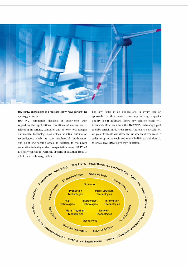
HARTING knowledge is practical know-how generating
synergy effects.
HARTING commands decades of experience with
regard to the applications conditions of connectors in
telecommunications, computer and network technologies
and medical technologies, as well as industrial automation
technologies, such as the mechanical engineering
and plant engineering areas, in addition to the power
generation industry or the transportation sector. HARTING
is highly conversant with the specific application areas in
all of these technology fields.
The key focus is on applications in every solution
approach. In this context, uncompromising, superior
quality is our hallmark. Every new solution found will
invariably flow back into the HARTING technology pool,
thereby enriching our resources. And every new solution
we go on to create will draw on this wealth of resources in
order to optimize each and every individual solution. In
this way, HARTING is synergy in action.
Mac
hine
ry
Tra
nsporta
tion S
olar Energy Wind Energy Power Generation and Distribution Automation Industrial Devices
Telecom Em
bedded Computing Systems Broadcast and Entertainment Medical Industria
l Netw
ork Infra
stru
ctur
e
Backplanes
Industrial Connectors Actuator Systems
Cab
le As
sem
blie
s
Asse
mbl
y lin
es
3D Micropackages Advanced Tools Vending Systems
PCB Technologies
InformationTechnologies
ProductionTechnologies
Metal TreatmentTechnologies
Micro StructureTechnologies
NetworkTechnologies
Simulation
InterconnectTechnologies
Mechatronic
Introduction
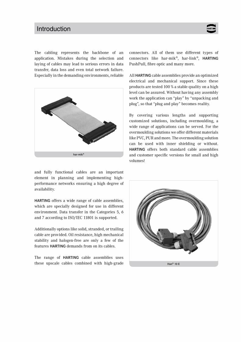
The cabling represents the backbone of an application. Mistakes during the selection and laying of cables may lead to serious errors in data transfer, data loss and even total network failure. Especially in the demanding environments, reliable
and fully functional cables are an important element in planning and implementing high-performance networks ensuring a high degree of availability.
HARTING offers a wide range of cable assemblies, which are specially designed for use in different environment. Data transfer in the Categories 5, 6 and 7 according to ISO/IEC 11801 is supported.
Additionally options like solid, stranded, or trailing cable are provided. Oil resistance, high mechanical stability and halogen-free are only a few of the features HARTING demands from on its cables.
The range of HARTING cable assemblies uses these upscale cables combined with high-grade
connectors. All of them use different types of connectors like har-mik®, har-link®, HARTING PushPull, fibre optic and many more.
All HARTING cable assemblies provide an optimized electrical and mechanical support. Since these products are tested 100 % a stable quality on a high level can be assured. Without having any assembly work the application can “play” by “unpacking and plug”, so that “plug and play” becomes reality.
By covering various lengths and supporting customized solutions, including overmoulding, a wide range of applications can be served. For the overmoulding solutions we offer different materials like PVC, PUR and more. The overmoulding solution can be used with inner shielding or without. HARTING offers both standard cable assemblies and customer specific versions for small and high volumes!
Han® 10 E
har-mik®
Chapter
Content
Indoor cable assemblies . . . . . . . . . . . . . . . . . . . . . . . . . . . . . . . . . . . . . . . . . 01
Outdoor cable assemblies . . . . . . . . . . . . . . . . . . . . . . . . . . . . . . . . . . . . . . . 02
Industrial Ethernet cable assemblies . . . . . . . . . . . . . . . . . . . . . . . . . . . . . . 03
Customized solutions . . . . . . . . . . . . . . . . . . . . . . . . . . . . . . . . . . . . . . . . . . . 04
Locations . . . . . . . . . . . . . . . . . . . . . . . . . . . . . . . . . . . . . . . . . . . . . . . . . . . . . 10
Chapter 01 – Indoor cable assemblies
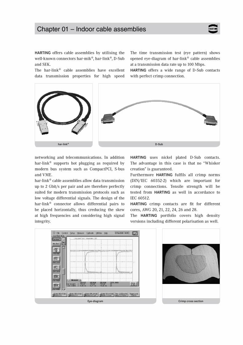
HARTING offers cable assemblies by utilising the well-known connectors har-mik®, har-link®, D-Sub and SEK. The har-link® cable assemblies have excellent data transmission properties for high speed
networking and telecommunications. In addition har-link® supports hot plugging as required by modern bus system such as CompactPCI, S-bus and VME.har-link® cable assemblies allow data transmission up to 2 Gbit/s per pair and are therefore perfectly suited for modern transmission protocols such as low voltage differential signals. The design of the har-link® connector allows differential pairs to be placed horizontally, thus creducing the skew at high frequencies and considering high signal integrity.
The time transmission test (eye pattern) shows opened eye-diagram of har-link® cable assemblies at a transmission data rate up to 100 Mbps.HARTING offers a wide range of D-Sub contacts with perfect crimp connection.
HARTING uses nickel plated D-Sub contacts. The advantage in this case is that no “Whisker creation” is guaranteed. Furthermore HARTING fulfils all crimp norms (DIN/IEC 60352-2) which are important for crimp connections. Tensile strength will be tested from HARTING as well in accordance to IEC 60512.HARTING crimp contacts are fit for different cores, AWG 20, 21, 22, 24, 26 and 28.The HARTING portfolio covers high density versions including different polarisation as well.
D-Sub
Eye-diagram
har-link®
Crimp cross section
01.01
Content Page
Chapter 01 – Indoor cable assemblies
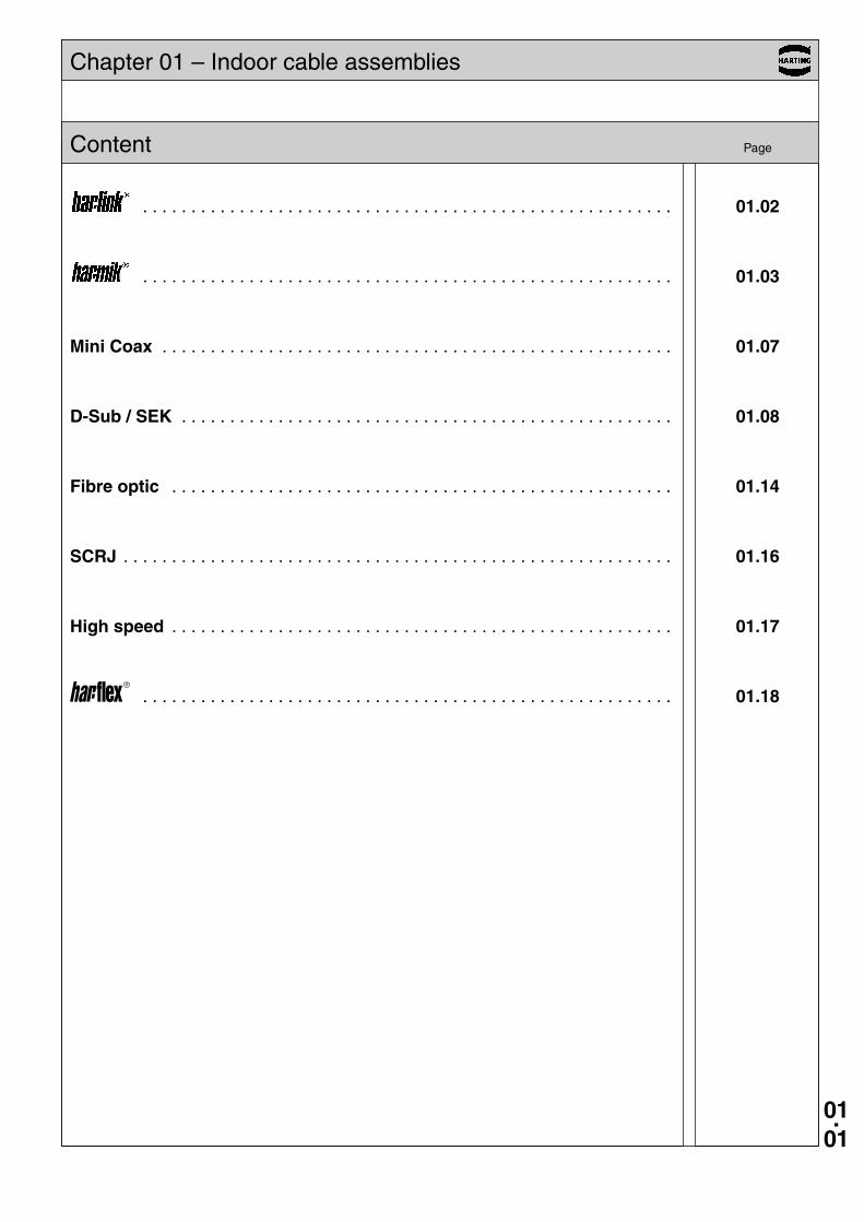
. . . . . . . . . . . . . . . . . . . . . . . . . . . . . . . . . . . . . . . . . . . . . . . . . . . . . . . 01.02
. . . . . . . . . . . . . . . . . . . . . . . . . . . . . . . . . . . . . . . . . . . . . . . . . . . . . . . 01.03
Mini Coax . . . . . . . . . . . . . . . . . . . . . . . . . . . . . . . . . . . . . . . . . . . . . . . . . . . . . 01.07
D-Sub / SEK . . . . . . . . . . . . . . . . . . . . . . . . . . . . . . . . . . . . . . . . . . . . . . . . . . . 01.08
Fibre optic . . . . . . . . . . . . . . . . . . . . . . . . . . . . . . . . . . . . . . . . . . . . . . . . . . . . 01.14
SCRJ . . . . . . . . . . . . . . . . . . . . . . . . . . . . . . . . . . . . . . . . . . . . . . . . . . . . . . . . . 01.16
High speed . . . . . . . . . . . . . . . . . . . . . . . . . . . . . . . . . . . . . . . . . . . . . . . . . . . . 01.17
. . . . . . . . . . . . . . . . . . . . . . . . . . . . . . . . . . . . . . . . . . . . . . . . . . . . . . . 01.18
01.02
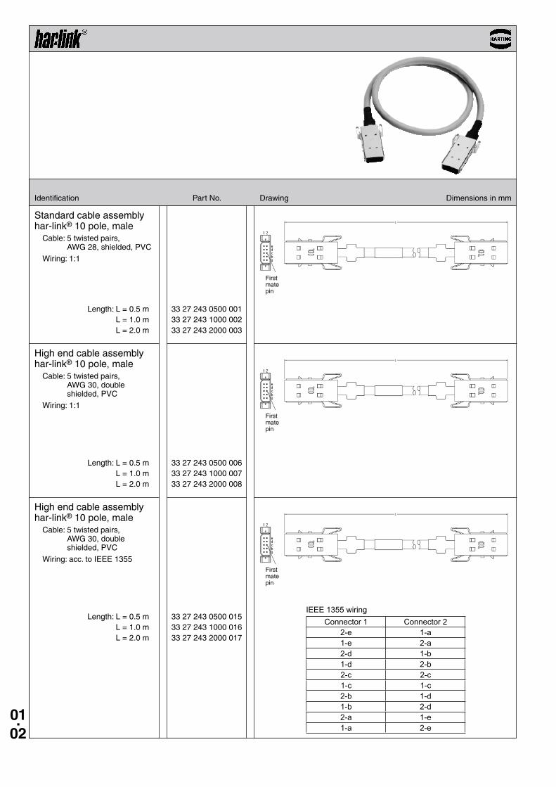
33 27 243 0500 001 33 27 243 1000 002 33 27 243 2000 003
33 27 243 0500 006 33 27 243 1000 007 33 27 243 2000 008
33 27 243 0500 015 33 27 243 1000 016 33 27 243 2000 017
Identification Part No . Drawing Dimensions in mm
First mate pin
First mate pin
First mate pin
Standard cable assembly har-link® 10 pole, male
Cable: 5 twisted pairs, AWG 28, shielded, PVC
Wiring: 1:1
Length: L = 0 .5 m L = 1 .0 m L = 2 .0 m
Length: L = 0 .5 m L = 1 .0 m L = 2 .0 m
High end cable assembly har-link® 10 pole, male
Cable: 5 twisted pairs, AWG 30, double shielded, PVC
Wiring: 1:1
Length: L = 0 .5 m L = 1 .0 m L = 2 .0 m
High end cable assembly har-link® 10 pole, male
Cable: 5 twisted pairs, AWG 30, double shielded, PVC
Wiring: acc . to IEEE 1355
IEEE 1355 wiringConnector 1 Connector 2
2-e 1-a1-e 2-a2-d 1-b1-d 2-b2-c 2-c1-c 1-c2-b 1-d1-b 2-d2-a 1-e1-a 2-e
01.03
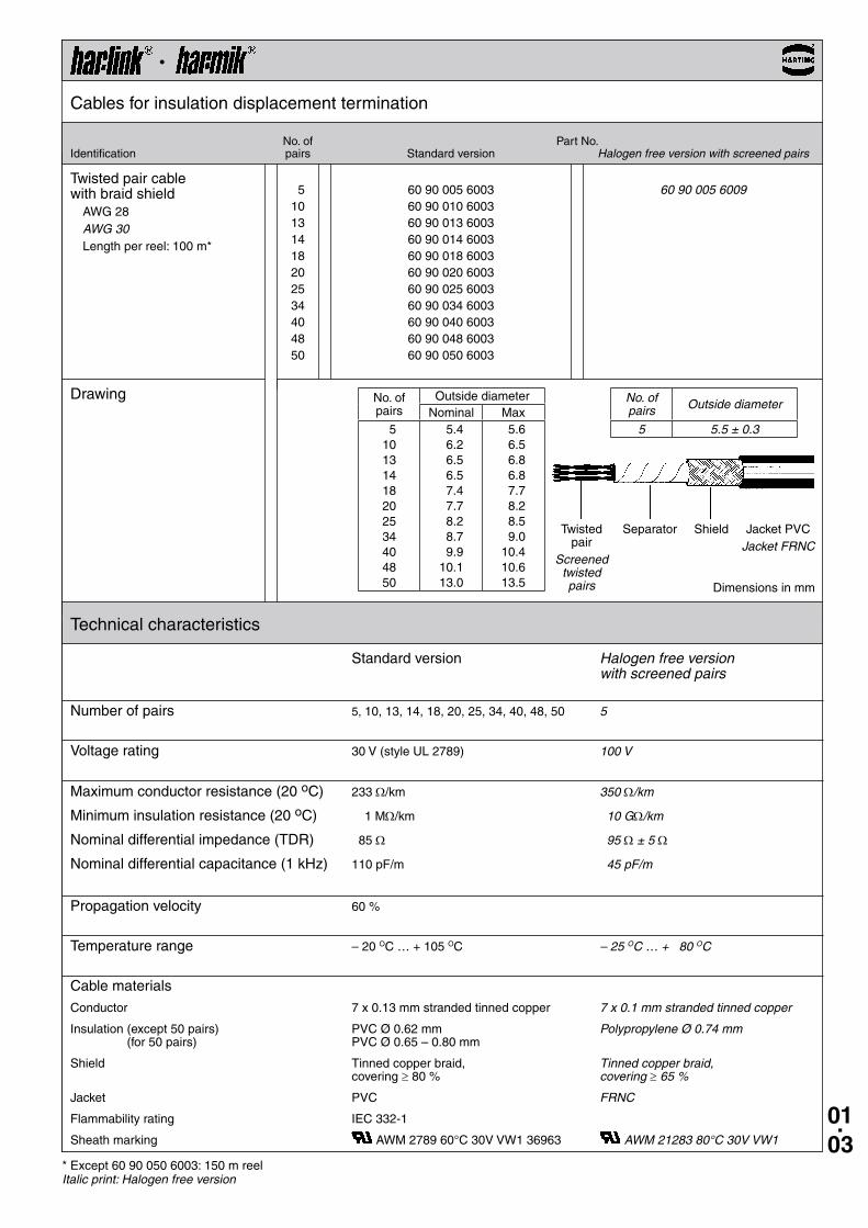
5 60 90 005 6003 60 90 005 6009 10 60 90 010 6003 13 60 90 013 6003 14 60 90 014 6003 18 60 90 018 6003 20 60 90 020 6003 25 60 90 025 6003 34 60 90 034 6003 40 60 90 040 6003 48 60 90 048 6003 50 60 90 050 6003
·Cables for insulation displacement termination
Twisted pair cable with braid shield
AWG 28AWG 30Length per reel: 100 m*
Drawing
No . of Part No .Identification pairs Standard version Halogen free version with screened pairs
Dimensions in mm
No . of pairs
Outside diameterNominal Max
510131418202534404850
5 .4 6 .2 6 .5 6 .5 7 .4 7 .7 8 .2 8 .7 9 .910 .113 .0
5 .6 6 .5 6 .8 6 .8 7 .7 8 .2 8 .5 9 .010 .410 .613 .5
No. of pairs Outside diameter
5 5.5 ± 0.3
Twisted pair
Screened twisted pairs
Separator Shield Jacket PVCJacket FRNC
Technical characteristics
Standard version Halogen free version with screened pairs
Number of pairs 5, 10, 13, 14, 18, 20, 25, 34, 40, 48, 50 5
Voltage rating 30 V (style UL 2789) 100 V
Maximum conductor resistance (20 oC) 233 Ω/km 350 Ω/km
Minimum insulation resistance (20 oC) 1 MΩ/km 10 GΩ/km
Nominal differential impedance (TDR) 85 Ω 95 Ω ± 5 Ω
Nominal differential capacitance (1 kHz) 110 pF/m 45 pF/m
Propagation velocity 60 %
Temperature range – 20 OC … + 105 OC – 25 OC … + 80 OC
Cable materials
Conductor 7 x 0 .13 mm stranded tinned copper 7 x 0.1 mm stranded tinned copper
Insulation (except 50 pairs) PVC Ø 0 .62 mm Polypropylene Ø 0.74 mm (for 50 pairs) PVC Ø 0 .65 – 0 .80 mm
Shield Tinned copper braid, Tinned copper braid, covering ≥ 80 % covering ≥ 65 %
Jacket PVC FRNC
Flammability rating IEC 332-1
Sheath marking AWM 2789 60°C 30V VW1 36963 AWM 21283 80°C 30V VW1
* Except 60 90 050 6003: 150 m reelItalic print: Halogen free version
01.04
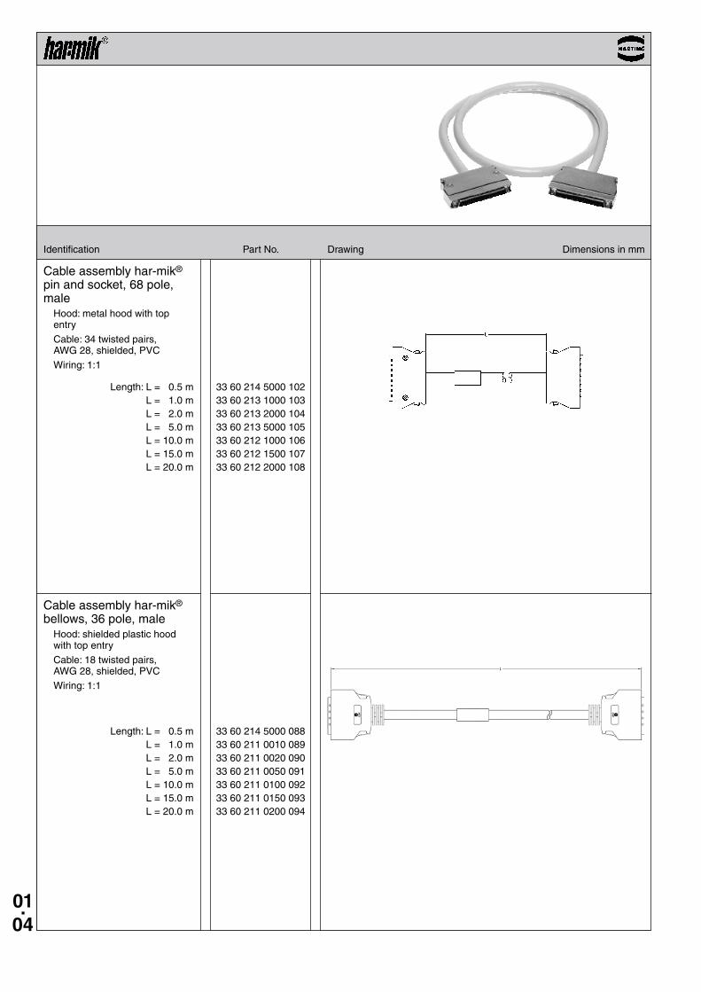
33 60 214 5000 102 33 60 213 1000 103 33 60 213 2000 104 33 60 213 5000 105 33 60 212 1000 106 33 60 212 1500 107 33 60 212 2000 108
33 60 214 5000 088 33 60 211 0010 089 33 60 211 0020 090 33 60 211 0050 091 33 60 211 0100 092 33 60 211 0150 093 33 60 211 0200 094
Identification Part No . Drawing Dimensions in mm
Cable assembly har-mik® pin and socket, 68 pole, male
Hood: metal hood with top entry
Cable: 34 twisted pairs, AWG 28, shielded, PVC
Wiring: 1:1
Length: L = 0 .5 m L = 1 .0 m L = 2 .0 m L = 5 .0 m L = 10 .0 m L = 15 .0 m L = 20 .0 m
Cable assembly har-mik® bellows, 36 pole, male
Hood: shielded plastic hood with top entry
Cable: 18 twisted pairs, AWG 28, shielded, PVC
Wiring: 1:1
Length: L = 0 .5 m L = 1 .0 m L = 2 .0 m L = 5 .0 m L = 10 .0 m L = 15 .0 m L = 20 .0 m
01.05
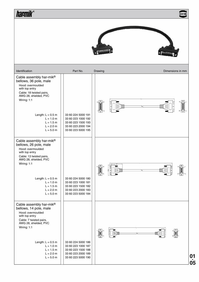
33 60 224 5000 191 33 60 223 1000 192 33 60 223 1500 193 33 60 223 2000 194 33 60 223 5000 195
33 60 224 5000 180 33 60 223 1000 181 33 60 223 1500 182 33 60 223 2000 183 33 60 223 5000 184
33 60 224 5000 186 33 60 223 1000 187 33 60 223 1500 188 33 60 223 2000 189 33 60 223 5000 190
Identification Part No . Drawing Dimensions in mm
Cable assembly har-mik® bellows, 36 pole, male
Hood: overmoulded with top entry
Cable: 18 twisted pairs, AWG 28, shielded, PVC
Wiring: 1:1
Cable assembly har-mik® bellows, 26 pole, male
Hood: overmoulded with top entry
Cable: 13 twisted pairs, AWG 28, shielded, PVC
Wiring: 1:1
Cable assembly har-mik® bellows, 14 pole, male
Hood: overmoulded with top entry
Cable: 7 twisted pairs, AWG 28, shielded, PVC
Wiring: 1:1
Length: L = 0 .5 m L = 1 .0 m L = 1 .5 m L = 2 .0 m L = 5 .0 m
Length: L = 0 .5 m L = 1 .0 m L = 1 .5 m L = 2 .0 m L = 5 .0 m
Length: L = 0 .5 m L = 1 .0 m L = 1 .5 m L = 2 .0 m L = 5 .0 m
01.06
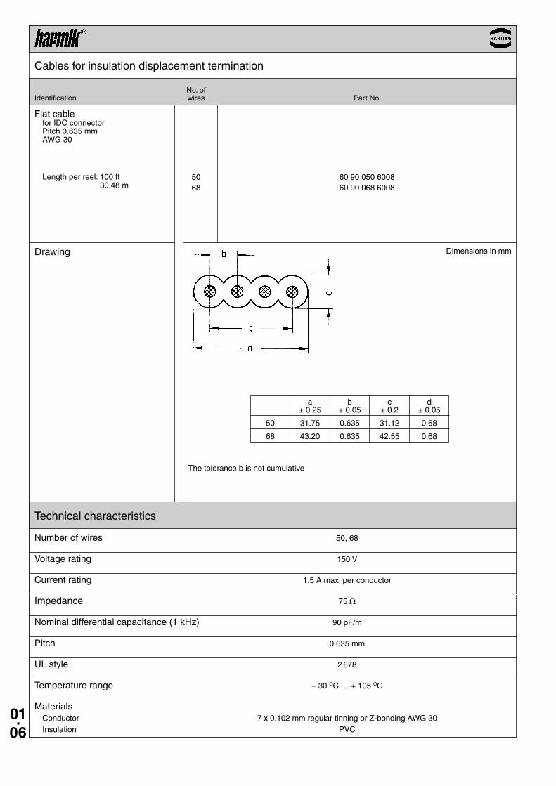
50 60 90 050 6008 68 60 90 068 6008
Cables for insulation displacement termination
Drawing
No . ofIdentification wires Part No .
Dimensions in mm
a b c d ± 0 .25 ± 0 .05 ± 0 .2 ± 0 .05
50 31 .75 0 .635 31 .12 0 .68
68 43 .20 0 .635 42 .55 0 .68
The tolerance b is not cumulative
Technical characteristics
Number of wires 50, 68
Voltage rating 150 V
Current rating 1 .5 A max . per conductor
Impedance 75 Ω
Nominal differential capacitance (1 kHz) 90 pF/m
Pitch 0 .635 mm
UL style 2 678
Temperature range – 30 OC … + 105 OC
Materials Conductor 7 x 0 .102 mm regular tinning or Z-bonding AWG 30 Insulation PVC
Flat cablefor IDC connectorPitch 0 .635 mmAWG 30
Length per reel: 100 ft 30 .48 m
01.07
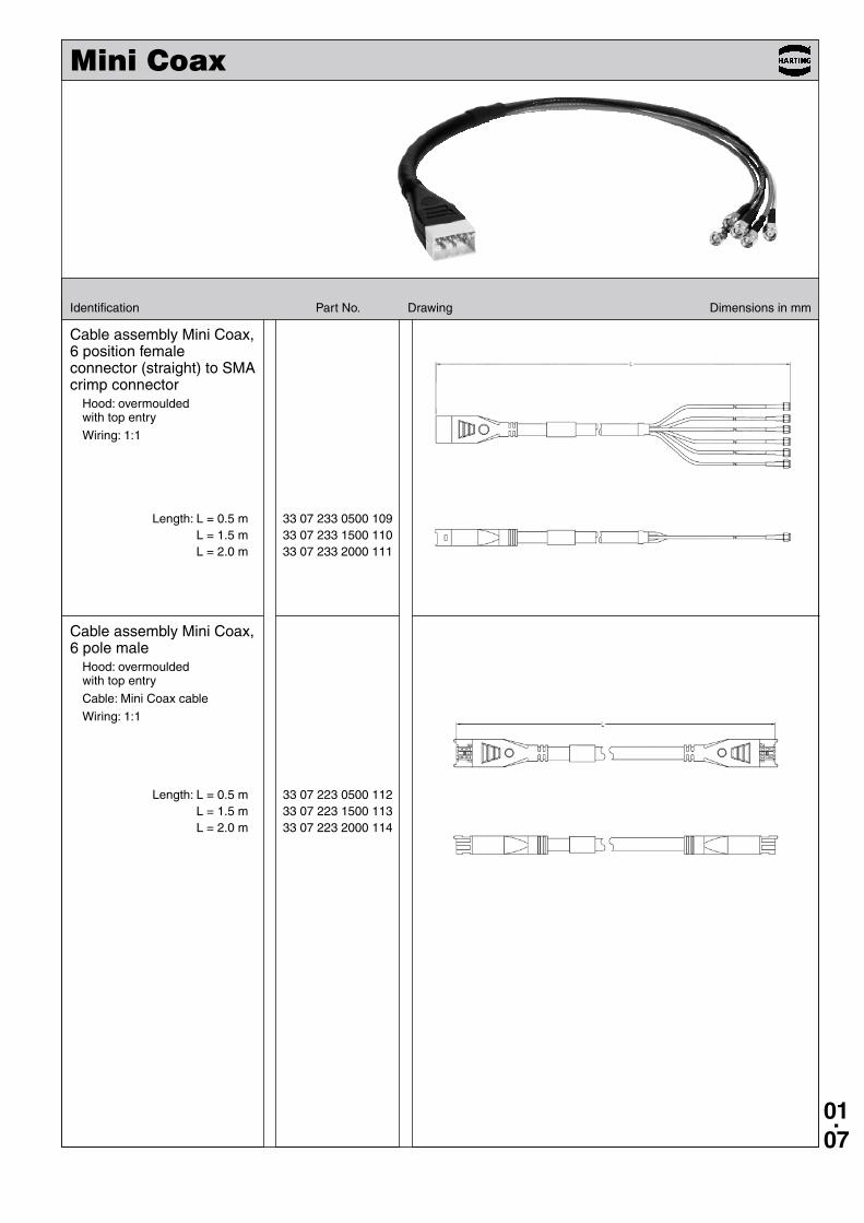
33 07 233 0500 109 33 07 233 1500 110 33 07 233 2000 111
33 07 223 0500 112 33 07 223 1500 113 33 07 223 2000 114
Mini Coax
Identification Part No . Drawing Dimensions in mm
Cable assembly Mini Coax, 6 position female connector (straight) to SMA crimp connector
Hood: overmoulded with top entry
Wiring: 1:1
Cable assembly Mini Coax, 6 pole male
Hood: overmoulded with top entry
Cable: Mini Coax cable
Wiring: 1:1
Length: L = 0 .5 m L = 1 .5 m L = 2 .0 m
Length: L = 0 .5 m L = 1 .5 m L = 2 .0 m
01.08
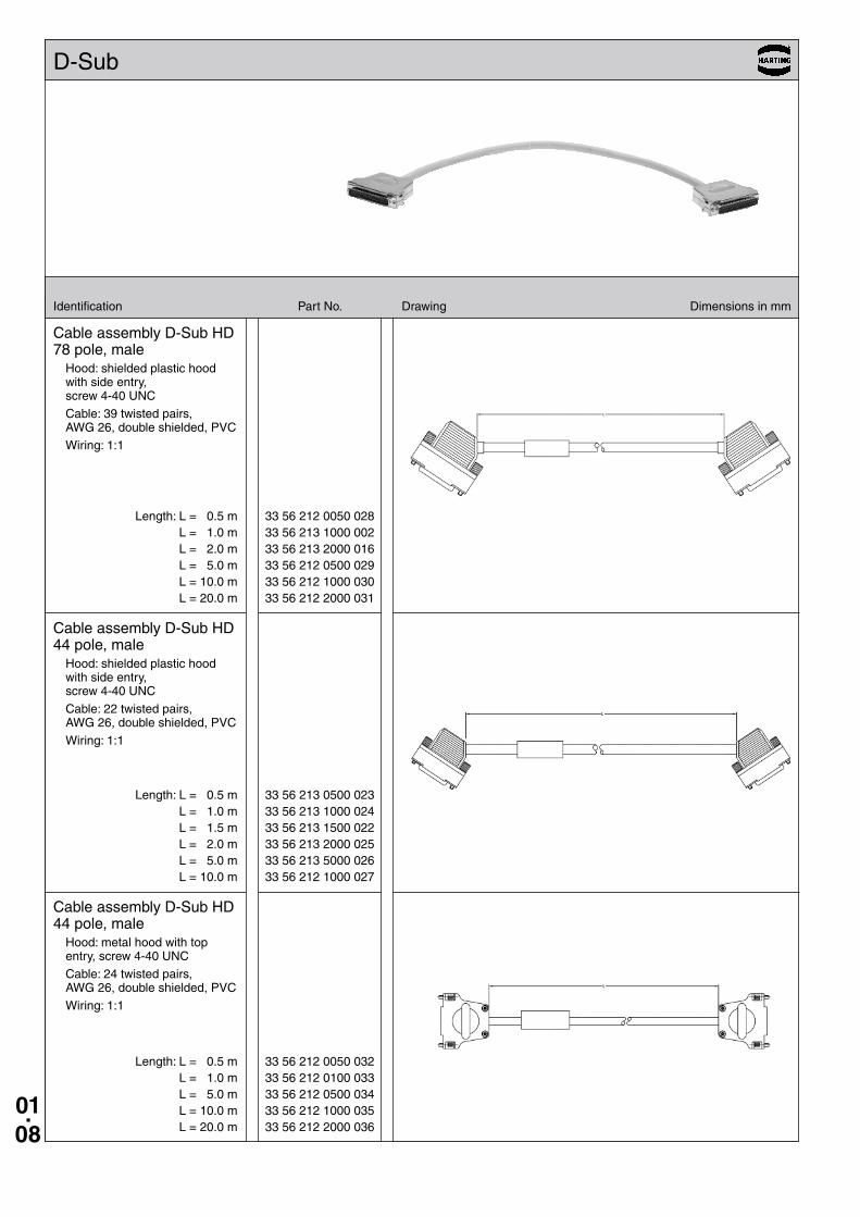
33 56 212 0050 028 33 56 213 1000 002 33 56 213 2000 016 33 56 212 0500 029 33 56 212 1000 030 33 56 212 2000 031
33 56 213 0500 023 33 56 213 1000 024 33 56 213 1500 022 33 56 213 2000 025 33 56 213 5000 026 33 56 212 1000 027
33 56 212 0050 032 33 56 212 0100 033 33 56 212 0500 034 33 56 212 1000 035 33 56 212 2000 036
Identification Part No . Drawing Dimensions in mm
D-Sub
Cable assembly D-Sub HD 78 pole, male
Hood: shielded plastic hood with side entry, screw 4-40 UNC
Cable: 39 twisted pairs, AWG 26, double shielded, PVC
Wiring: 1:1
Length: L = 0 .5 m L = 1 .0 m L = 2 .0 m L = 5 .0 m L = 10 .0 m L = 20 .0 m
Cable assembly D-Sub HD 44 pole, male
Hood: shielded plastic hood with side entry, screw 4-40 UNC
Cable: 22 twisted pairs, AWG 26, double shielded, PVC
Wiring: 1:1
Length: L = 0 .5 m L = 1 .0 m L = 1 .5 m L = 2 .0 m L = 5 .0 m L = 10 .0 m
Cable assembly D-Sub HD 44 pole, male
Hood: metal hood with top entry, screw 4-40 UNC
Cable: 24 twisted pairs, AWG 26, double shielded, PVC
Wiring: 1:1
Length: L = 0 .5 m L = 1 .0 m L = 5 .0 m L = 10 .0 m L = 20 .0 m
01.09
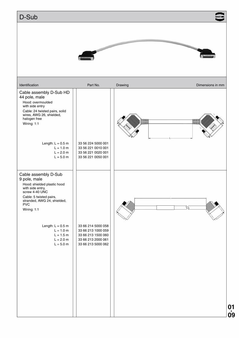
33 56 224 5000 001 33 56 221 0010 001 33 56 221 0020 001 33 56 221 0050 001
33 66 214 5000 058 33 66 213 1000 059 33 66 213 1500 060 33 66 213 2000 061 33 66 213 5000 062
Identification Part No . Drawing Dimensions in mm
D-Sub
Cable assembly D-Sub HD 44 pole, male
Hood: overmoulded with side entry
Cable: 24 twisted pairs, solid wires, AWG 26, shielded, halogen free
Wiring: 1:1
Length: L = 0 .5 m L = 1 .0 m L = 2 .0 m L = 5 .0 m
Cable assembly D-Sub 9 pole, male
Hood: shielded plastic hood with side entry, screw 4-40 UNC
Cable: 5 twisted pairs, stranded, AWG 24, shielded, PVC
Wiring: 1:1
Length: L = 0 .5 m L = 1 .0 m L = 1 .5 m L = 2 .0 m L = 5 .0 m
01.10
33 18 243 0500 060 33 18 243 1000 062 33 18 243 1500 068
33 18 243 0500 055 33 18 243 1000 057 33 18 243 1500 069
33 18 243 0100 063 33 18 243 0200 064 33 18 243 0500 065 33 18 243 0800 066 33 18 243 1000 067
Identification Part No . Drawing Dimensions in mm
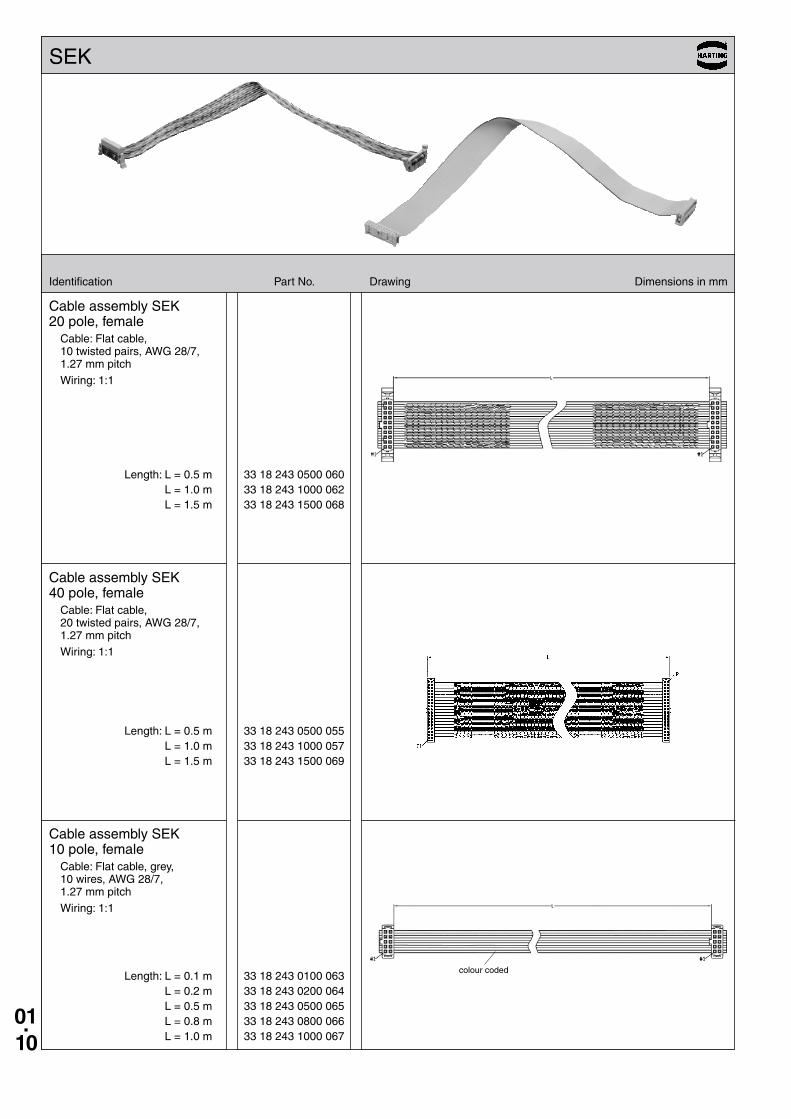
SEK
Cable assembly SEK 20 pole, female
Cable: Flat cable, 10 twisted pairs, AWG 28/7, 1 .27 mm pitch
Wiring: 1:1
Length: L = 0 .5 m L = 1 .0 m L = 1 .5 m
Cable assembly SEK 40 pole, female
Cable: Flat cable, 20 twisted pairs, AWG 28/7, 1 .27 mm pitch
Wiring: 1:1
Length: L = 0 .5 m L = 1 .0 m L = 1 .5 m
Cable assembly SEK 10 pole, female
Cable: Flat cable, grey, 10 wires, AWG 28/7, 1 .27 mm pitch
Wiring: 1:1
Length: L = 0 .1 m L = 0 .2 m L = 0 .5 m L = 0 .8 m L = 1 .0 m
colour coded
01.11
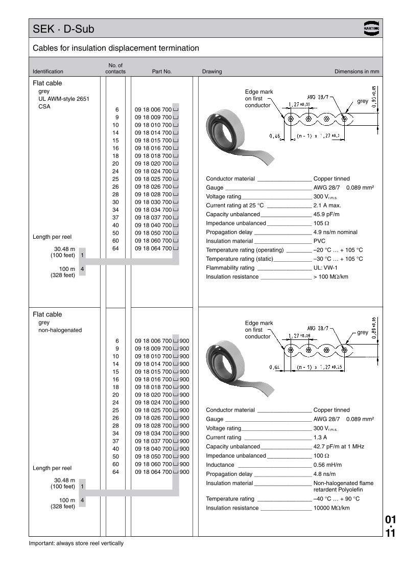
6 09 18 006 700 9 09 18 009 700 10 09 18 010 700 14 09 18 014 700 15 09 18 015 700 16 09 18 016 700 18 09 18 018 700 20 09 18 020 700 24 09 18 024 700 25 09 18 025 700 26 09 18 026 700 28 09 18 028 700 30 09 18 030 700 34 09 18 034 700 37 09 18 037 700 40 09 18 040 700 50 09 18 050 700 60 09 18 060 700 64 09 18 064 700
6 09 18 006 700 900 9 09 18 009 700 900 10 09 18 010 700 900 14 09 18 014 700 900 15 09 18 015 700 900 16 09 18 016 700 900 18 09 18 018 700 900 20 09 18 020 700 900 24 09 18 024 700 900 25 09 18 025 700 900 26 09 18 026 700 900 28 09 18 028 700 900 34 09 18 034 700 900 37 09 18 037 700 900 40 09 18 040 700 900 50 09 18 050 700 900 60 09 18 060 700 900 64 09 18 064 700 900
Cables for insulation displacement termination
Important: always store reel vertically
No . ofIdentification contacts Part No . Drawing Dimensions in mm
Flat cablegreyUL AWM-style 2651CSA
Flat cablegreynon-halogenated
Length per reel
30 .48 m (100 feet) 1
100 m 4 (328 feet)
Length per reel
30 .48 m (100 feet) 1
100 m 4 (328 feet)
Conductor material _________________ Copper tinned
Gauge ___________________________ AWG 28/7 0 .089 mm²
Voltage rating ______________________ 300 Vr .m .s .
Current rating at 25 °C ______________ 2 .1 A max .
Capacity unbalanced ________________ 45 .9 pF/m
Impedance unbalanced ______________ 105 Ω
Propagation delay __________________ 4 .9 ns/m nominal
Insulation material __________________ PVC
Temperature rating (operating) ________ –20 °C … + 105 °C
Temperature rating (static) ____________ –30 °C … + 105 °C
Flammability rating _________________ UL: VW-1
Insulation resistance ________________ > 100 MΩ/km
Conductor material _________________ Copper tinned
Gauge ___________________________ AWG 28/7 0 .089 mm²
Voltage rating ______________________ 300 Vr .m .s .
Current rating _____________________ 1 .3 A
Capacity unbalanced ________________ 42 .7 pF/m at 1 MHz
Impedance unbalanced ______________ 100 Ω
Inductance _______________________ 0 .56 mH/m
Propagation delay __________________ 4 .8 ns/m
Insulation material __________________ Non-halogenated flame retardent Polyolefin
Temperature rating _________________ –40 °C … + 90 °C
Insulation resistance ________________ 10000 MΩ/km
grey
grey
Edge mark on first conductor
Edge mark on first conductor
SEK · D-Sub
01.12
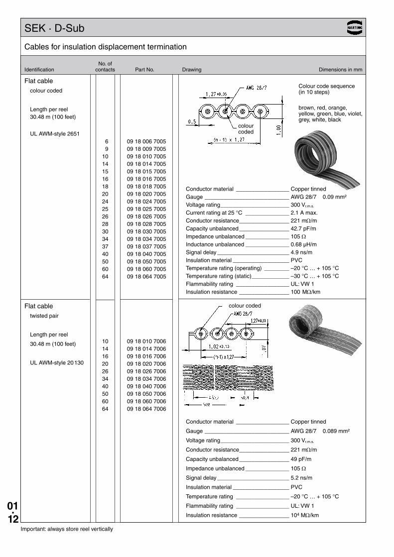
6 09 18 006 7005 9 09 18 009 7005 10 09 18 010 7005 14 09 18 014 7005 15 09 18 015 7005 16 09 18 016 7005 18 09 18 018 7005 20 09 18 020 7005 24 09 18 024 7005 25 09 18 025 7005 26 09 18 026 7005 28 09 18 028 7005 30 09 18 030 7005 34 09 18 034 7005 37 09 18 037 7005 40 09 18 040 7005 50 09 18 050 7005 60 09 18 060 7005 64 09 18 064 7005
10 09 18 010 7006 14 09 18 014 7006 16 09 18 016 7006 20 09 18 020 7006 26 09 18 026 7006 34 09 18 034 7006 40 09 18 040 7006 50 09 18 050 7006 60 09 18 060 7006 64 09 18 064 7006
Cables for insulation displacement termination
Important: always store reel vertically
No . ofIdentification contacts Part No . Drawing Dimensions in mm
Flat cablecolour coded
Length per reel30 .48 m (100 feet)
UL AWM-style 2651
Conductor material _________________ Copper tinnedGauge ___________________________ AWG 28/7 0 .09 mm²Voltage rating ______________________ 300 Vr .m .s .
Current rating at 25 °C ______________ 2 .1 A max .Conductor resistance ________________ 221 mΩ/mCapacity unbalanced ________________ 42 .7 pF/mImpedance unbalanced ______________ 105 ΩInductance unbalanced ______________ 0 .68 µH/mSignal delay _______________________ 4 .9 ns/mInsulation material __________________ PVCTemperature rating (operating) ________ –20 °C … + 105 °CTemperature rating (static) ____________ –30 °C … + 105 °CFlammability rating _________________ UL: VW 1Insulation resistance ________________ 100 MΩ/km
Conductor material _________________ Copper tinned
Gauge ___________________________ AWG 28/7 0 .089 mm²
Voltage rating ______________________ 300 Vr .m .s .
Conductor resistance ________________ 221 mΩ/m
Capacity unbalanced ________________ 49 pF/m
Impedance unbalanced ______________ 105 Ω
Signal delay _______________________ 5 .2 ns/m
Insulation material __________________ PVC
Temperature rating _________________ –20 °C … + 105 °C
Flammability rating _________________ UL: VW 1
Insulation resistance ________________ 104 MΩ/km
Colour code sequence (in 10 steps)
brown, red, orange, yellow, green, blue, violet, grey, white, black
colour coded
SEK · D-Sub
Flat cabletwisted pair
Length per reel
30 .48 m (100 feet)
UL AWM-style 20 130
colour coded
01.13
SEK · D-Sub
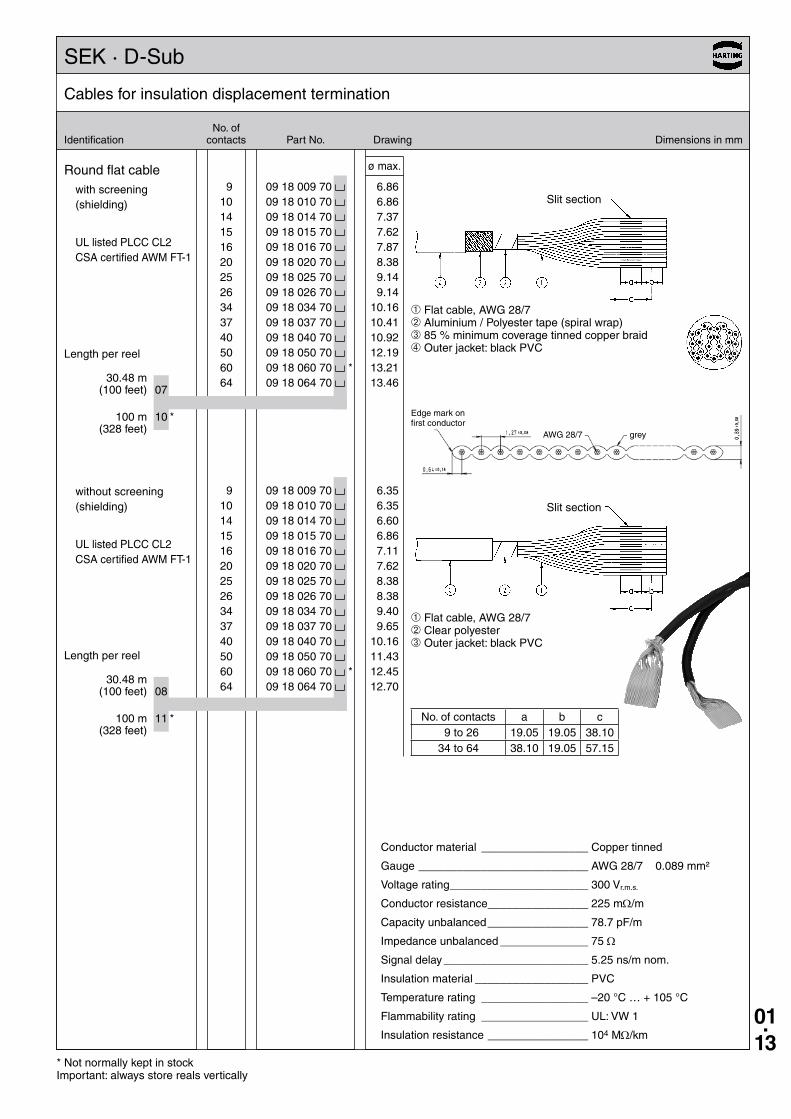
9 09 18 009 70 10 09 18 010 70 14 09 18 014 70 15 09 18 015 70 16 09 18 016 70 20 09 18 020 70 25 09 18 025 70 26 09 18 026 70 34 09 18 034 70 37 09 18 037 70 40 09 18 040 70 50 09 18 050 70 60 09 18 060 70 * 64 09 18 064 70
9 09 18 009 70 10 09 18 010 70 14 09 18 014 70 15 09 18 015 70 16 09 18 016 70 20 09 18 020 70 25 09 18 025 70 26 09 18 026 70 34 09 18 034 70 37 09 18 037 70 40 09 18 040 70 50 09 18 050 70 60 09 18 060 70 * 64 09 18 064 70
Cables for insulation displacement termination
* Not normally kept in stockImportant: always store reals vertically
No . ofIdentification contacts Part No . Drawing Dimensions in mm
Round flat cablewith screening (shielding)
UL listed PLCC CL2 CSA certified AWM FT-1
Length per reel
30 .48 m (100 feet) 07
100 m 10 * (328 feet)
without screening (shielding)
UL listed PLCC CL2 CSA certified AWM FT-1
Length per reel
30 .48 m (100 feet) 08
100 m 11 * (328 feet)
➀ Flat cable, AWG 28/7➁ Clear polyester➂ Outer jacket: black PVC
No . of contacts a b c 9 to 26 19 .05 19 .05 38 .1034 to 64 38 .10 19 .05 57 .15
➀ Flat cable, AWG 28/7➁ Aluminium / Polyester tape (spiral wrap)➂ 85 % minimum coverage tinned copper braid➃ Outer jacket: black PVC
Edge mark on first conductor
AWG 28/7 grey
Slit section
Slit section
6 .35 6 .35 6 .60 6 .86 7 .11 7 .62 8 .38 8 .38 9 .40 9 .6510 .1611 .4312 .4512 .70
ø max .
6 .86 6 .86 7 .37 7 .62 7 .87 8 .38 9 .14 9 .1410 .1610 .4110 .9212 .1913 .2113 .46
Conductor material _________________ Copper tinned
Gauge ___________________________ AWG 28/7 0 .089 mm²
Voltage rating ______________________ 300 Vr .m .s .
Conductor resistance ________________ 225 mΩ/m
Capacity unbalanced ________________ 78 .7 pF/m
Impedance unbalanced ______________ 75 Ω
Signal delay _______________________ 5 .25 ns/m nom .
Insulation material __________________ PVC
Temperature rating _________________ –20 °C … + 105 °C
Flammability rating _________________ UL: VW 1
Insulation resistance ________________ 104 MΩ/km
01.14
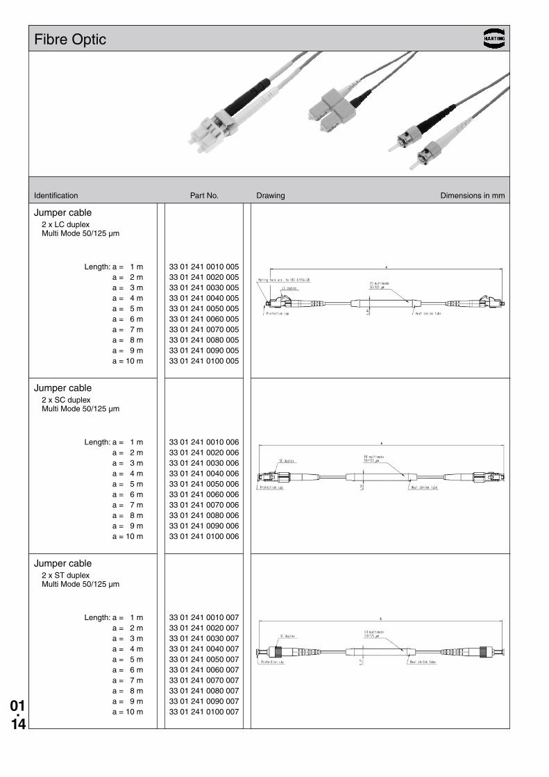
33 01 241 0010 005 33 01 241 0020 005 33 01 241 0030 005 33 01 241 0040 005 33 01 241 0050 005 33 01 241 0060 005 33 01 241 0070 005 33 01 241 0080 005 33 01 241 0090 005 33 01 241 0100 005
33 01 241 0010 006 33 01 241 0020 006 33 01 241 0030 006 33 01 241 0040 006 33 01 241 0050 006 33 01 241 0060 006 33 01 241 0070 006 33 01 241 0080 006 33 01 241 0090 006 33 01 241 0100 006
33 01 241 0010 007 33 01 241 0020 007 33 01 241 0030 007 33 01 241 0040 007 33 01 241 0050 007 33 01 241 0060 007 33 01 241 0070 007 33 01 241 0080 007 33 01 241 0090 007 33 01 241 0100 007
Identification Part No . Drawing Dimensions in mm
Fibre Optic
Jumper cable2 x LC duplex Multi Mode 50/125 µm
Jumper cable2 x SC duplex Multi Mode 50/125 µm
Jumper cable2 x ST duplex Multi Mode 50/125 µm
Length: a = 1 m a = 2 m a = 3 m a = 4 m a = 5 m a = 6 m a = 7 m a = 8 m a = 9 m a = 10 m
Length: a = 1 m a = 2 m a = 3 m a = 4 m a = 5 m a = 6 m a = 7 m a = 8 m a = 9 m a = 10 m
Length: a = 1 m a = 2 m a = 3 m a = 4 m a = 5 m a = 6 m a = 7 m a = 8 m a = 9 m a = 10 m
01.15
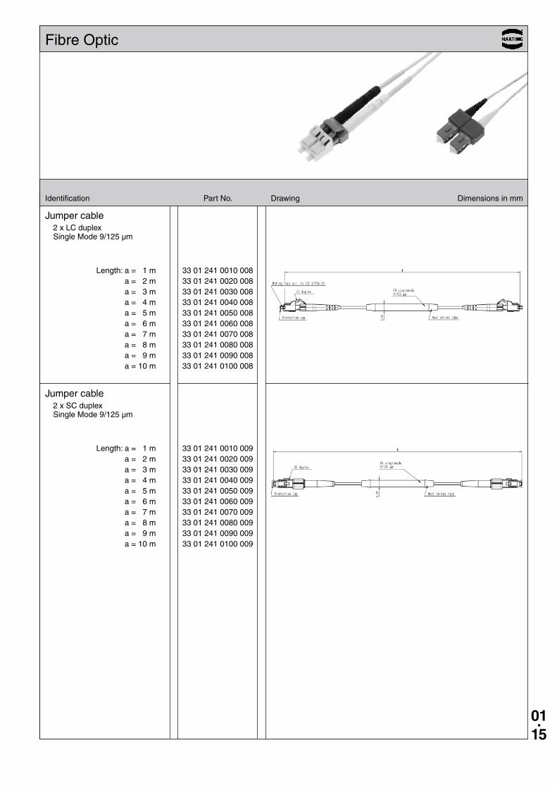
33 01 241 0010 008 33 01 241 0020 008 33 01 241 0030 008 33 01 241 0040 008 33 01 241 0050 008 33 01 241 0060 008 33 01 241 0070 008 33 01 241 0080 008 33 01 241 0090 008 33 01 241 0100 008
33 01 241 0010 009 33 01 241 0020 009 33 01 241 0030 009 33 01 241 0040 009 33 01 241 0050 009 33 01 241 0060 009 33 01 241 0070 009 33 01 241 0080 009 33 01 241 0090 009 33 01 241 0100 009
Identification Part No . Drawing Dimensions in mm
Fibre Optic
Jumper cable2 x LC duplex Single Mode 9/125 µm
Jumper cable2 x SC duplex Single Mode 9/125 µm
Length: a = 1 m a = 2 m a = 3 m a = 4 m a = 5 m a = 6 m a = 7 m a = 8 m a = 9 m a = 10 m
Length: a = 1 m a = 2 m a = 3 m a = 4 m a = 5 m a = 6 m a = 7 m a = 8 m a = 9 m a = 10 m
01.16
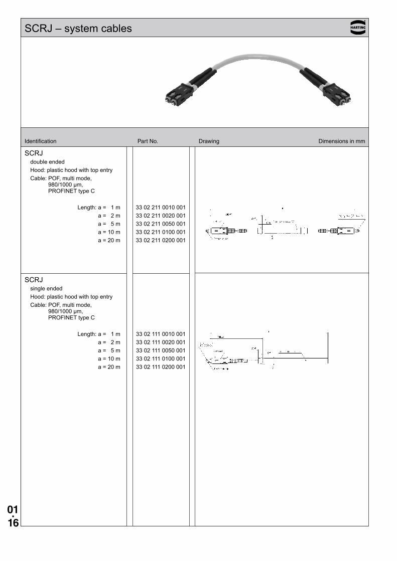
SCRJdouble endedHood: plastic hood with top entryCable: POF, multi mode,
980/1000 µm, PROFINET type C
Length: a = 1 m 33 02 211 0010 001a = 2 m 33 02 211 0020 001a = 5 m 33 02 211 0050 001a = 10 m 33 02 211 0100 001a = 20 m 33 02 211 0200 001
SCRJsingle endedHood: plastic hood with top entryCable: POF, multi mode,
980/1000 µm, PROFINET type C
Length: a = 1 m 33 02 111 0010 001a = 2 m 33 02 111 0020 001a = 5 m 33 02 111 0050 001a = 10 m 33 02 111 0100 001a = 20 m 33 02 111 0200 001
SCRJ – system cables
Identification Part No . Drawing Dimensions in mm
01.17
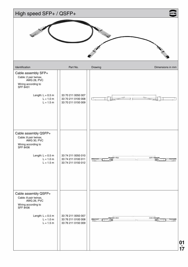
33 70 211 0050 007 33 70 211 0100 008 33 70 211 0150 009
33 74 211 0050 010 33 74 211 0100 011 33 74 211 0150 012
33 76 211 0050 007 33 76 211 0100 008 33 76 211 0150 009
Identification Part No . Drawing Dimensions in mm
High speed SFP+ / QSFP+
Cable assembly SFP+Cable: 2 pair twinax,
AWG 28, PVC
Wiring according to SFF 8431
Cable assembly QSFP+Cable: 8 pair twinax,
AWG 30, PVC
Wiring according to SFF 8436
Cable assembly QSFP+Cable: 8 pair twinax,
AWG 26, PVC
Wiring according to SFF 8436
Length: L = 0 .5 m L = 1 .0 m L = 1 .5 m
Length: L = 0 .5 m L = 1 .0 m L = 1 .5 m
Length: L = 0 .5 m L = 1 .0 m L = 1 .5 m
01.18
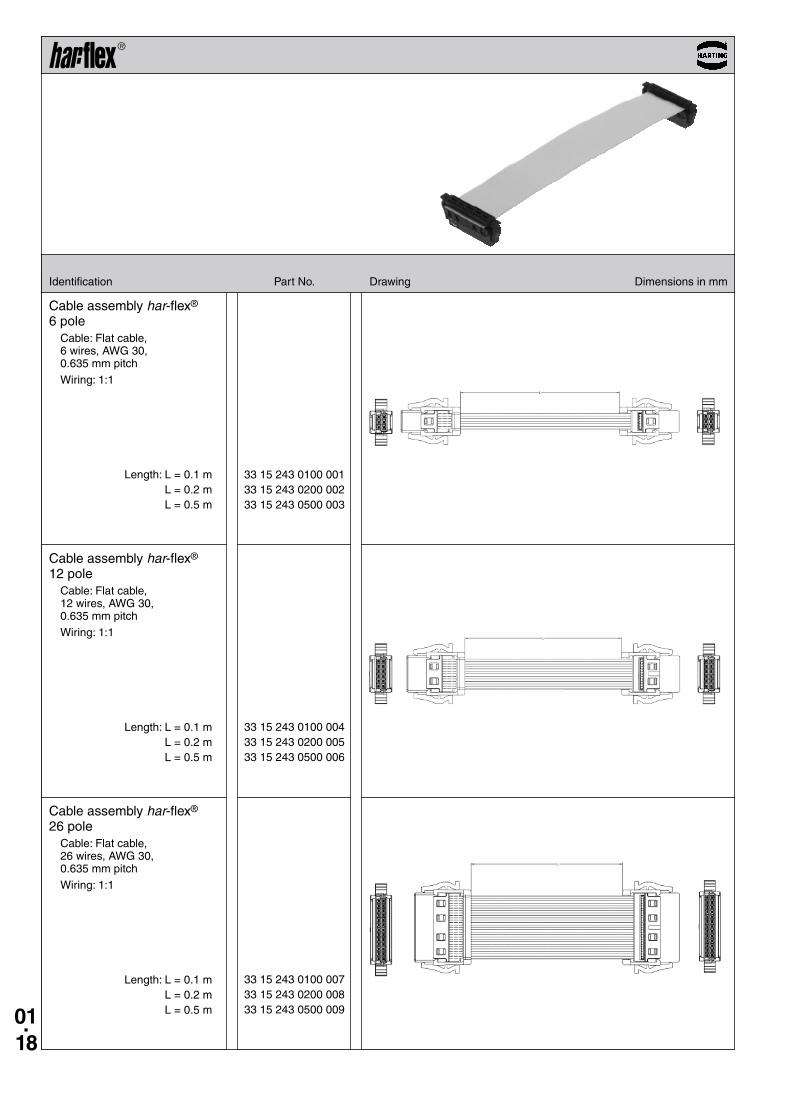
33 15 243 0100 001 33 15 243 0200 002 33 15 243 0500 003
33 15 243 0100 004 33 15 243 0200 005 33 15 243 0500 006
33 15 243 0100 007 33 15 243 0200 008 33 15 243 0500 009
Identification Part No . Drawing Dimensions in mm
Length: L = 0 .1 m L = 0 .2 m L = 0 .5 m
Length: L = 0 .1 m L = 0 .2 m L = 0 .5 m
Length: L = 0 .1 m L = 0 .2 m L = 0 .5 m
Cable assembly har-flex® 6 pole
Cable: Flat cable, 6 wires, AWG 30, 0 .635 mm pitch
Wiring: 1:1
Cable assembly har-flex® 12 pole
Cable: Flat cable, 12 wires, AWG 30, 0 .635 mm pitch
Wiring: 1:1
Cable assembly har-flex® 26 pole
Cable: Flat cable, 26 wires, AWG 30, 0 .635 mm pitch
Wiring: 1:1
01.19
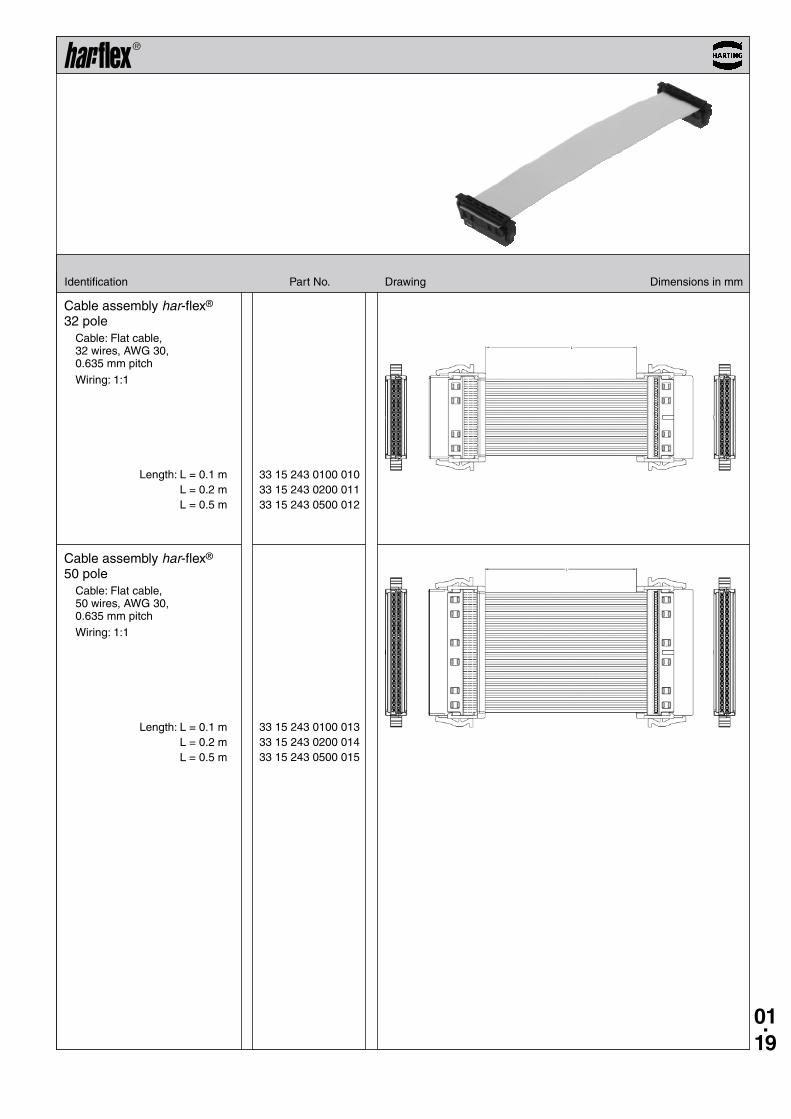
33 15 243 0100 010 33 15 243 0200 011 33 15 243 0500 012
33 15 243 0100 013 33 15 243 0200 014 33 15 243 0500 015
Identification Part No . Drawing Dimensions in mm
Length: L = 0 .1 m L = 0 .2 m L = 0 .5 m
Length: L = 0 .1 m L = 0 .2 m L = 0 .5 m
Cable assembly har-flex® 32 pole
Cable: Flat cable, 32 wires, AWG 30, 0 .635 mm pitch
Wiring: 1:1
Cable assembly har-flex® 50 pole
Cable: Flat cable, 50 wires, AWG 30, 0 .635 mm pitch
Wiring: 1:1
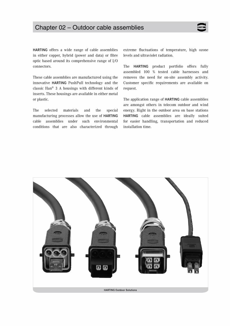
Chapter 02 – Outdoor cable assemblies
HARTING offers a wide range of cable assemblies in either copper, hybrid (power and data) or fibre optic based around its comprehensive range of I/O connectors.
These cable assemblies are manufactured using the innovative HARTING PushPull technology and the classic Han® 3 A housings with different kinds of inserts. These housings are available in either metal or plastic.
The selected materials and the special manufacturing processes allow the use of HARTING cable assemblies under such environmental conditions that are also characterized through
extreme fluctuations of temperature, high ozone levels and ultraviolet radiation.
The HARTING product portfolio offers fully assembled 100 % tested cable harnesses and removes the need for on-site assembly activity. Customer specific requirements are available on request.
The application range of HARTING cable assemblies are amongst others in telecom outdoor and wind energy. Right in the outdoor area on base stations HARTING cable assemblies are ideally suited for easier handling, transportation and reduced installation time.
HARTING Outdoor Solutions
02.01
Content Page
Chapter 02 – Outdoor cable assemblies
HARTING PushPull, Fibre optic, LC duplex . . . . . . . . . . . . . . . . . . . . . . . . . 02.02
Han® 3 A, Fibre optic, 2 x LC duplex . . . . . . . . . . . . . . . . . . . . . . . . . . . . . . . 02.09
Han® 3 A, Hybrid fibre optic, LC duplex . . . . . . . . . . . . . . . . . . . . . . . . . . . . 02.11
Han® 3 A, Hybrid RJ45 . . . . . . . . . . . . . . . . . . . . . . . . . . . . . . . . . . . . . . . . . . 02.13
Han® 3 A, RJ45 · HARTING PushPull, RJ45 . . . . . . . . . . . . . . . . . . . . . . . . . . 02.14
02.02
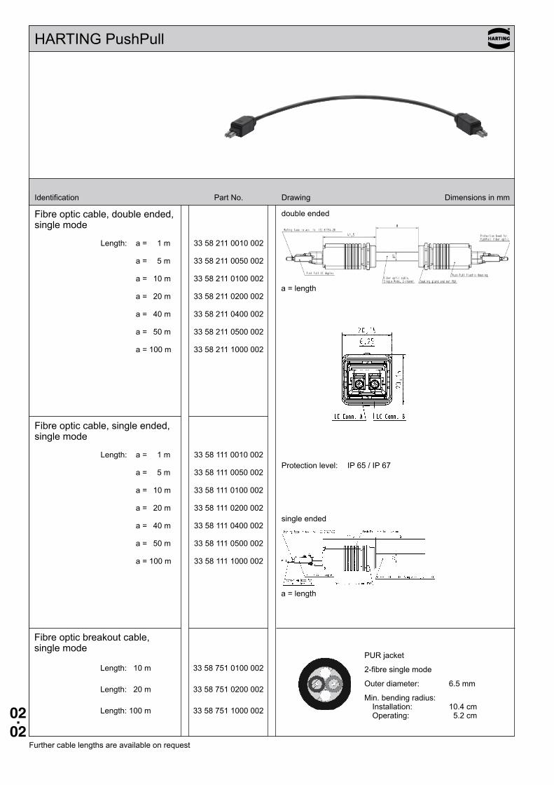
HARTING PushPull
Identification Part No. Drawing Dimensions in mm
Fibre optic cable, double ended, single mode
Length: a = 1 m 33 58 211 0010 002
a = 5 m 33 58 211 0050 002
a = 10 m 33 58 211 0100 002
a = 20 m 33 58 211 0200 002
a = 40 m 33 58 211 0400 002
a = 50 m 33 58 211 0500 002
a = 100 m 33 58 211 1000 002
Fibre optic cable, single ended, single mode
Length: a = 1 m 33 58 111 0010 002
a = 5 m 33 58 111 0050 002
a = 10 m 33 58 111 0100 002
a = 20 m 33 58 111 0200 002
a = 40 m 33 58 111 0400 002
a = 50 m 33 58 111 0500 002
a = 100 m 33 58 111 1000 002
Protection level: IP 65 / IP 67
double ended
single ended
Further cable lengths are available on request
Fibre optic breakout cable, single mode
Length: 10 m 33 58 751 0100 002
Length: 20 m 33 58 751 0200 002
Length: 100 m 33 58 751 1000 002
PUR jacket
2-fibre single mode
Outer diameter: 6.5 mm
Min. bending radius: Installation: 10.4 cm Operating: 5.2 cm
a = length
a = length

02.03
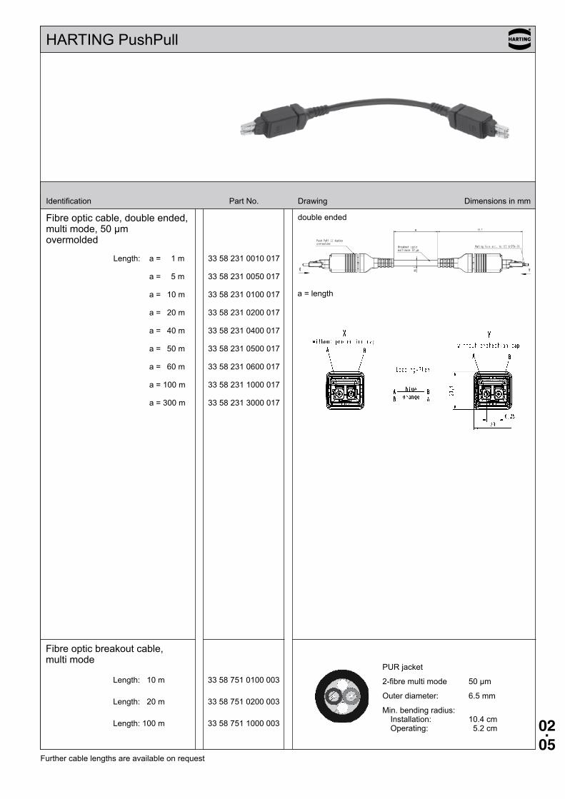
HARTING PushPull
Identification Part No. Drawing Dimensions in mm
Fibre optic cable, double ended, single mode overmolded
Length: a = 1 m 33 58 231 0010 015
a = 5 m 33 58 231 0050 015
a = 10 m 33 58 231 0100 015
a = 20 m 33 58 231 0200 015
a = 40 m 33 58 231 0400 015
a = 50 m 33 58 231 0500 015
a = 60 m 33 58 231 0600 015
a = 100 m 33 58 231 1000 015
a = 300 m 33 58 231 3000 015
double ended
Further cable lengths are available on request
Fibre optic breakout cable, single mode
Length: 10 m 33 58 751 0100 002
Length: 20 m 33 58 751 0200 002
Length: 100 m 33 58 751 1000 002
PUR jacket
2-fibre single mode
Outer diameter: 6.5 mm
Min. bending radius: Installation: 10.4 cm Operating: 5.2 cm
a = length
02.04
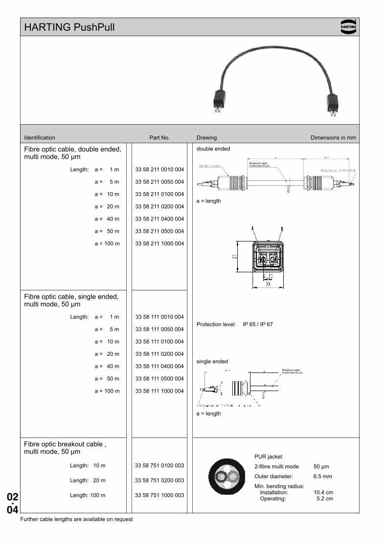
HARTING PushPull
Identification Part No. Drawing Dimensions in mm
Fibre optic cable, double ended, multi mode, 50 µm
Length: a = 1 m 33 58 211 0010 004
a = 5 m 33 58 211 0050 004
a = 10 m 33 58 211 0100 004
a = 20 m 33 58 211 0200 004
a = 40 m 33 58 211 0400 004
a = 50 m 33 58 211 0500 004
a = 100 m 33 58 211 1000 004
Fibre optic cable, single ended, multi mode, 50 µm
Length: a = 1 m 33 58 111 0010 004
a = 5 m 33 58 111 0050 004
a = 10 m 33 58 111 0100 004
a = 20 m 33 58 111 0200 004
a = 40 m 33 58 111 0400 004
a = 50 m 33 58 111 0500 004
a = 100 m 33 58 111 1000 004
Protection level: IP 65 / IP 67
double ended
single ended
Further cable lengths are available on request
Fibre optic breakout cable , multi mode, 50 µm
Length: 10 m 33 58 751 0100 003
Length: 20 m 33 58 751 0200 003
Length: 100 m 33 58 751 1000 003
PUR jacket
2-fibre multi mode 50 µm
Outer diameter: 6.5 mm
Min. bending radius: Installation: 10.4 cm Operating: 5.2 cm
a = length
a = length
Breakout cable multimode 50 µm
Ø 6
.5
Breakout cable multimode 50 µm
Ø 6
.5
02.05
HARTING PushPull
Identification Part No. Drawing Dimensions in mm
Fibre optic cable, double ended, multi mode, 50 µm overmolded
Length: a = 1 m 33 58 231 0010 017
a = 5 m 33 58 231 0050 017
a = 10 m 33 58 231 0100 017
a = 20 m 33 58 231 0200 017
a = 40 m 33 58 231 0400 017
a = 50 m 33 58 231 0500 017
a = 60 m 33 58 231 0600 017
a = 100 m 33 58 231 1000 017
a = 300 m 33 58 231 3000 017
double ended
Further cable lengths are available on request
Fibre optic breakout cable, multi mode
Length: 10 m 33 58 751 0100 003
Length: 20 m 33 58 751 0200 003
Length: 100 m 33 58 751 1000 003
PUR jacket
2-fibre multi mode 50 µm
Outer diameter: 6.5 mm
Min. bending radius: Installation: 10.4 cm Operating: 5.2 cm
a = length
02.06
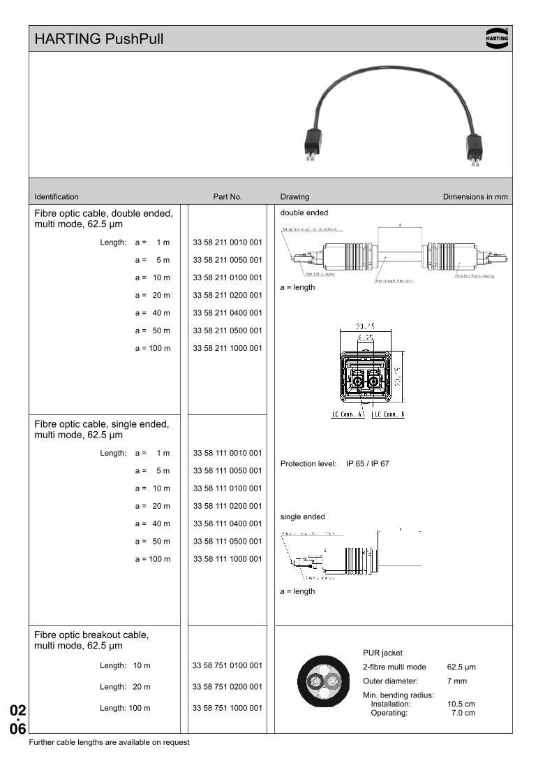
HARTING PushPull
Identification Part No. Drawing Dimensions in mm
Fibre optic cable, double ended, multi mode, 62.5 µm
Length: a = 1 m 33 58 211 0010 001
a = 5 m 33 58 211 0050 001
a = 10 m 33 58 211 0100 001
a = 20 m 33 58 211 0200 001
a = 40 m 33 58 211 0400 001
a = 50 m 33 58 211 0500 001
a = 100 m 33 58 211 1000 001
Fibre optic cable, single ended, multi mode, 62.5 µm
Length: a = 1 m 33 58 111 0010 001
a = 5 m 33 58 111 0050 001
a = 10 m 33 58 111 0100 001
a = 20 m 33 58 111 0200 001
a = 40 m 33 58 111 0400 001
a = 50 m 33 58 111 0500 001
a = 100 m 33 58 111 1000 001
Protection level: IP 65 / IP 67
double ended
single ended
Further cable lengths are available on request
Fibre optic breakout cable, multi mode, 62.5 µm
Length: 10 m 33 58 751 0100 001
Length: 20 m 33 58 751 0200 001
Length: 100 m 33 58 751 1000 001
PUR jacket
2-fibre multi mode 62.5 µm
Outer diameter: 7 mm
Min. bending radius: Installation: 10.5 cm Operating: 7.0 cm
a = length
a = length
02.07
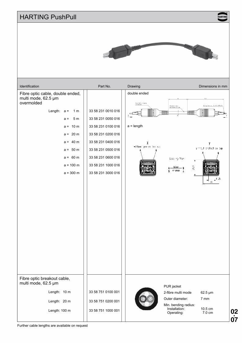
Fibre optic breakout cable, multi mode, 62.5 µm
Length: 10 m 33 58 751 0100 001
Length: 20 m 33 58 751 0200 001
Length: 100 m 33 58 751 1000 001
PUR jacket
2-fibre multi mode 62.5 µm
Outer diameter: 7 mm
Min. bending radius: Installation: 10.5 cm Operating: 7.0 cm
HARTING PushPull
Identification Part No. Drawing Dimensions in mm
Fibre optic cable, double ended, multi mode, 62.5 µm overmolded
Length: a = 1 m 33 58 231 0010 016
a = 5 m 33 58 231 0050 016
a = 10 m 33 58 231 0100 016
a = 20 m 33 58 231 0200 016
a = 40 m 33 58 231 0400 016
a = 50 m 33 58 231 0500 016
a = 60 m 33 58 231 0600 016
a = 100 m 33 58 231 1000 016
a = 300 m 33 58 231 3000 016
double ended
Further cable lengths are available on request
a = length
02.08
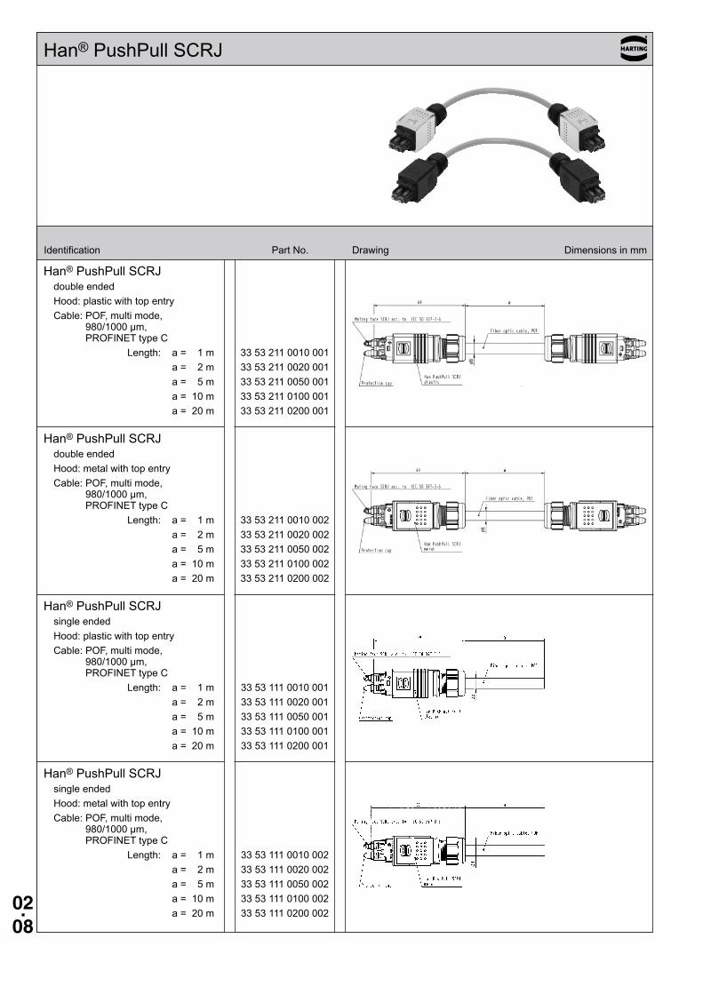
Han® PushPull SCRJ
Identification Part No. Drawing Dimensions in mm
Han® PushPull SCRJdouble endedHood: metal with top entryCable: POF, multi mode,
980/1000 µm, PROFINET type C
Length: a = 1 m 33 53 211 0010 002 a = 2 m 33 53 211 0020 002 a = 5 m 33 53 211 0050 002 a = 10 m 33 53 211 0100 002 a = 20 m 33 53 211 0200 002
Han® PushPull SCRJsingle endedHood: plastic with top entryCable: POF, multi mode,
980/1000 µm, PROFINET type C
Length: a = 1 m 33 53 111 0010 001 a = 2 m 33 53 111 0020 001 a = 5 m 33 53 111 0050 001 a = 10 m 33 53 111 0100 001 a = 20 m 33 53 111 0200 001
Han® PushPull SCRJsingle endedHood: metal with top entryCable: POF, multi mode,
980/1000 µm, PROFINET type C
Length: a = 1 m 33 53 111 0010 002 a = 2 m 33 53 111 0020 002 a = 5 m 33 53 111 0050 002 a = 10 m 33 53 111 0100 002 a = 20 m 33 53 111 0200 002
Han® PushPull SCRJdouble endedHood: plastic with top entryCable: POF, multi mode,
980/1000 µm, PROFINET type C
Length: a = 1 m 33 53 211 0010 001 a = 2 m 33 53 211 0020 001 a = 5 m 33 53 211 0050 001 a = 10 m 33 53 211 0100 001 a = 20 m 33 53 211 0200 001
02.09
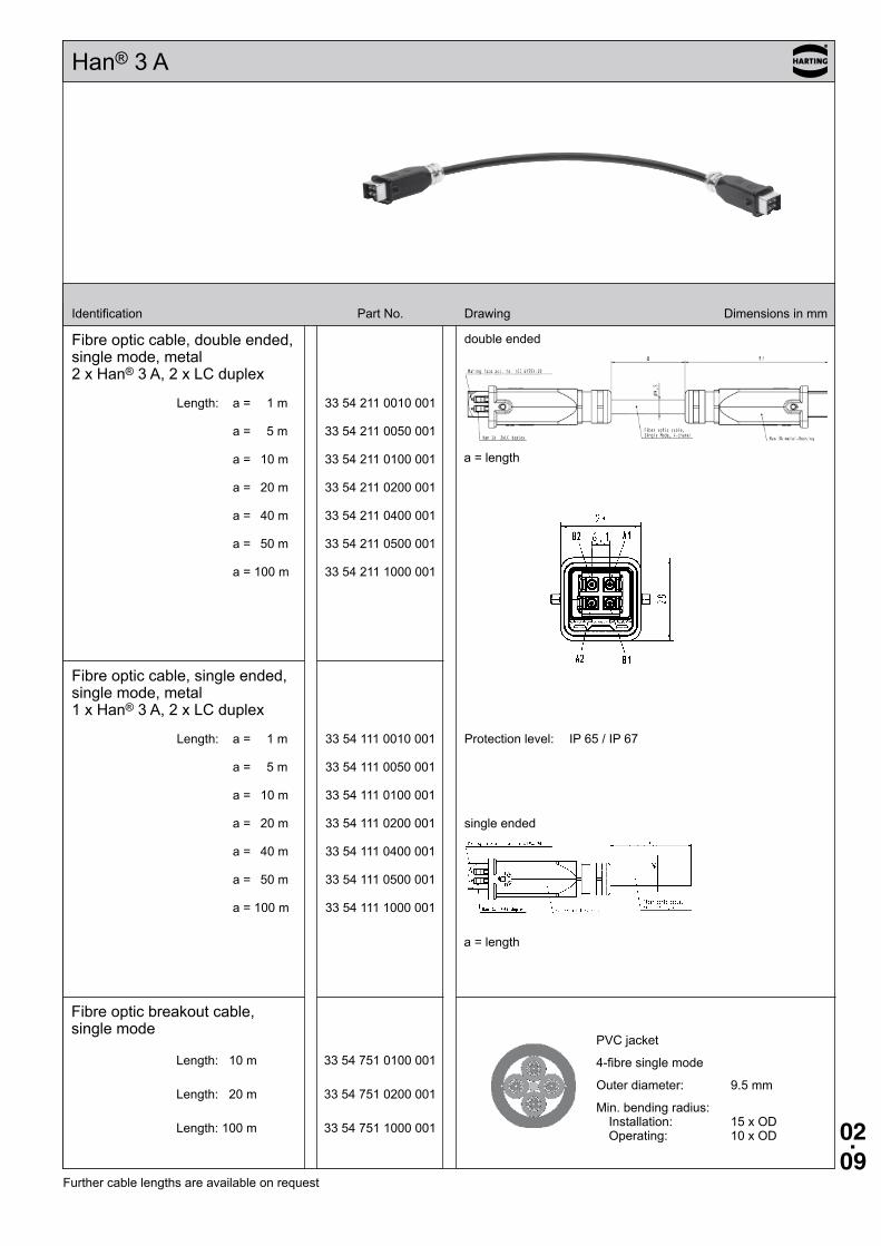
Han® 3 A
Fibre optic cable, double ended, single mode, metal 2 x Han® 3 A, 2 x LC duplex
Length: a = 1 m 33 54 211 0010 001
a = 5 m 33 54 211 0050 001
a = 10 m 33 54 211 0100 001
a = 20 m 33 54 211 0200 001
a = 40 m 33 54 211 0400 001
a = 50 m 33 54 211 0500 001
a = 100 m 33 54 211 1000 001
Fibre optic cable, single ended, single mode, metal 1 x Han® 3 A, 2 x LC duplex
Length: a = 1 m 33 54 111 0010 001
a = 5 m 33 54 111 0050 001
a = 10 m 33 54 111 0100 001
a = 20 m 33 54 111 0200 001
a = 40 m 33 54 111 0400 001
a = 50 m 33 54 111 0500 001
a = 100 m 33 54 111 1000 001
Protection level: IP 65 / IP 67
double ended
single ended
Further cable lengths are available on request
a = length
a = length
Fibre optic breakout cable, single mode
Length: 10 m 33 54 751 0100 001
Length: 20 m 33 54 751 0200 001
Length: 100 m 33 54 751 1000 001
PVC jacket
4-fibre single mode
Outer diameter: 9.5 mm
Min. bending radius: Installation: 15 x OD Operating: 10 x OD
Identification Part No. Drawing Dimensions in mm
02.10
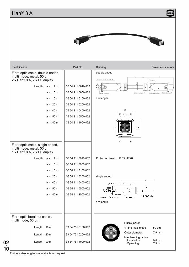
Han® 3 A
Identification Part No. Drawing Dimensions in mm
Fibre optic cable, double ended, multi mode, metal, 50 µm 2 x Han® 3 A, 2 x LC duplex
Length: a = 1 m 33 54 211 0010 002
a = 5 m 33 54 211 0050 002
a = 10 m 33 54 211 0100 002
a = 20 m 33 54 211 0200 002
a = 40 m 33 54 211 0400 002
a = 50 m 33 54 211 0500 002
a = 100 m 33 54 211 1000 002
Fibre optic cable, single ended, multi mode, metal, 50 µm 1 x Han® 3 A, 2 x LC duplex
Length: a = 1 m 33 54 111 0010 002
a = 5 m 33 54 111 0050 002
a = 10 m 33 54 111 0100 002
a = 20 m 33 54 111 0200 002
a = 40 m 33 54 111 0400 002
a = 50 m 33 54 111 0500 002
a = 100 m 33 54 111 1000 002
Protection level: IP 65 / IP 67
double ended
single ended
Further cable lengths are available on request
a = length
a = length
Fibre optic breakout cable , multi mode, 50 µm
Length: 10 m 33 54 751 0100 002
Length: 20 m 33 54 751 0200 002
Length: 100 m 33 54 751 1000 002
FRNC jacket
4-fibre multi mode 50 µm
Outer diameter: 7.9 mm
Min. bending radius: Installation: 9.8 cm Operating: 7.9 cm
02.11
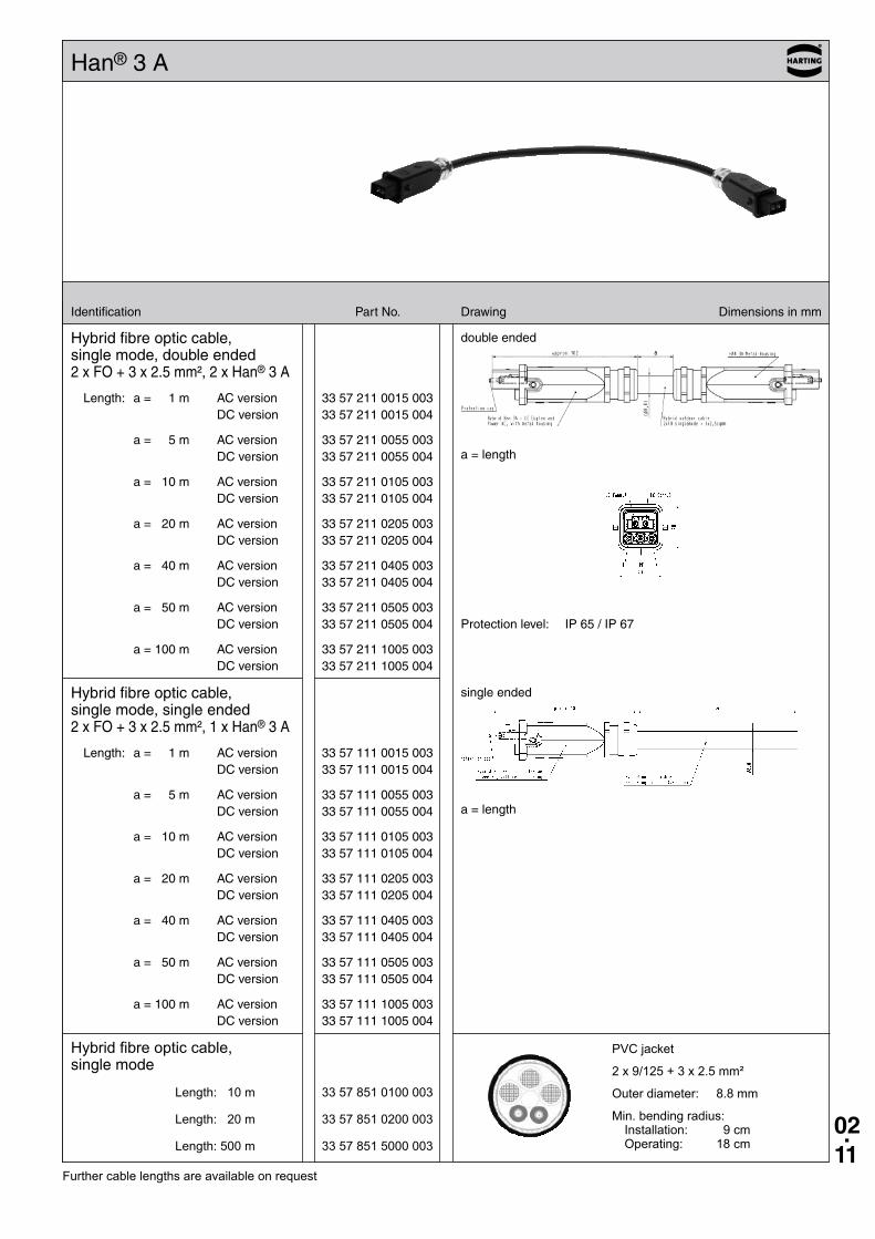
Hybrid fibre optic cable, single mode
Length: 10 m 33 57 851 0100 003
Length: 20 m 33 57 851 0200 003
Length: 500 m 33 57 851 5000 003
PVC jacket
2 x 9/125 + 3 x 2.5 mm²
Outer diameter: 8.8 mm
Min. bending radius: Installation: 9 cm Operating: 18 cm
Han® 3 A
Identification Part No . Drawing Dimensions in mm
Further cable lengths are available on request
Hybrid fibre optic cable, single mode, double ended 2 x FO + 3 x 2 .5 mm², 2 x Han® 3 A
Length: a = 1 m AC version 33 57 211 0015 003 DC version 33 57 211 0015 004
a = 5 m AC version 33 57 211 0055 003 DC version 33 57 211 0055 004
a = 10 m AC version 33 57 211 0105 003 DC version 33 57 211 0105 004
a = 20 m AC version 33 57 211 0205 003 DC version 33 57 211 0205 004
a = 40 m AC version 33 57 211 0405 003 DC version 33 57 211 0405 004
a = 50 m AC version 33 57 211 0505 003 DC version 33 57 211 0505 004
a = 100 m AC version 33 57 211 1005 003 DC version 33 57 211 1005 004
Hybrid fibre optic cable, single mode, single ended 2 x FO + 3 x 2 .5 mm², 1 x Han® 3 A
Length: a = 1 m AC version 33 57 111 0015 003 DC version 33 57 111 0015 004
a = 5 m AC version 33 57 111 0055 003 DC version 33 57 111 0055 004
a = 10 m AC version 33 57 111 0105 003 DC version 33 57 111 0105 004
a = 20 m AC version 33 57 111 0205 003 DC version 33 57 111 0205 004
a = 40 m AC version 33 57 111 0405 003 DC version 33 57 111 0405 004
a = 50 m AC version 33 57 111 0505 003 DC version 33 57 111 0505 004
a = 100 m AC version 33 57 111 1005 003 DC version 33 57 111 1005 004
Protection level: IP 65 / IP 67
double ended
single ended
a = length
a = length
02.12
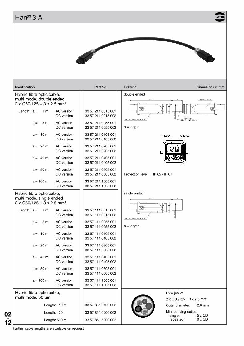
Hybrid fibre optic cable, multi mode, 50 µm
Length: 10 m 33 57 851 0100 002
Length: 20 m 33 57 851 0200 002
Length: 500 m 33 57 851 5000 002
PVC jacket
2 x G50/125 + 3 x 2.5 mm²
Outer diameter: 12.6 mm
Min. bending radius: single: 5 x OD repeated: 10 x OD
Han® 3 A
Identification Part No . Drawing Dimensions in mm
Further cable lengths are available on request
Hybrid fibre optic cable, multi mode, double ended 2 x G50/125 + 3 x 2 .5 mm²
Length: a = 1 m AC version 33 57 211 0015 001 DC version 33 57 211 0015 002
a = 5 m AC version 33 57 211 0055 001 DC version 33 57 211 0055 002
a = 10 m AC version 33 57 211 0105 001 DC version 33 57 211 0105 002
a = 20 m AC version 33 57 211 0205 001 DC version 33 57 211 0205 002
a = 40 m AC version 33 57 211 0405 001 DC version 33 57 211 0405 002
a = 50 m AC version 33 57 211 0505 001 DC version 33 57 211 0505 002
a = 100 m AC version 33 57 211 1005 001 DC version 33 57 211 1005 002
Hybrid fibre optic cable, multi mode, single ended 2 x G50/125 + 3 x 2 .5 mm²
Length: a = 1 m AC version 33 57 111 0015 001 DC version 33 57 111 0015 002
a = 5 m AC version 33 57 111 0055 001 DC version 33 57 111 0055 002
a = 10 m AC version 33 57 111 0105 001 DC version 33 57 111 0105 002
a = 20 m AC version 33 57 111 0205 001 DC version 33 57 111 0205 002
a = 40 m AC version 33 57 111 0405 001 DC version 33 57 111 0405 002
a = 50 m AC version 33 57 111 0505 001 DC version 33 57 111 0505 002
a = 100 m AC version 33 57 111 1005 001 DC version 33 57 111 1005 002
Protection level: IP 65 / IP 67
double ended
single ended
a = length
a = length
mm²
02.13
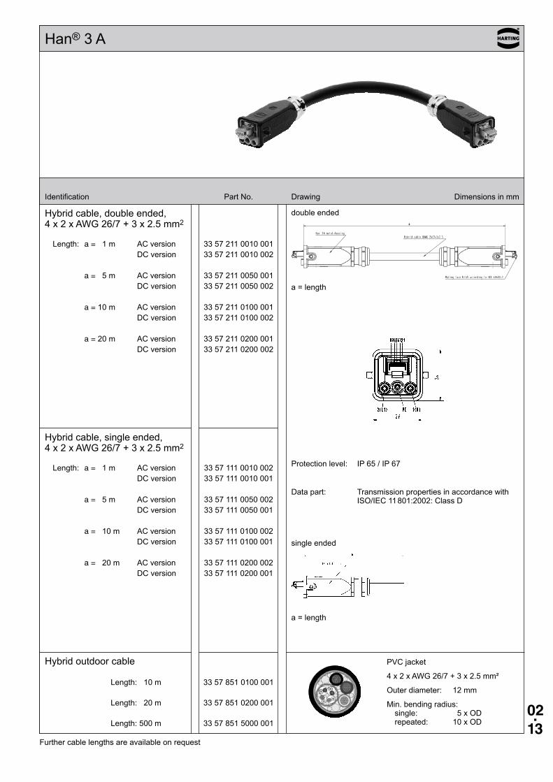
Han® 3 A
Identification Part No. Drawing Dimensions in mm
Hybrid cable, double ended, 4 x 2 x AWG 26/7 + 3 x 2.5 mm2
Length: a = 1 m AC version 33 57 211 0010 001 DC version 33 57 211 0010 002
a = 5 m AC version 33 57 211 0050 001 DC version 33 57 211 0050 002
a = 10 m AC version 33 57 211 0100 001 DC version 33 57 211 0100 002
a = 20 m AC version 33 57 211 0200 001 DC version 33 57 211 0200 002
Hybrid cable, single ended, 4 x 2 x AWG 26/7 + 3 x 2.5 mm2
Length: a = 1 m AC version 33 57 111 0010 002 DC version 33 57 111 0010 001
a = 5 m AC version 33 57 111 0050 002 DC version 33 57 111 0050 001
a = 10 m AC version 33 57 111 0100 002 DC version 33 57 111 0100 001
a = 20 m AC version 33 57 111 0200 002 DC version 33 57 111 0200 001
Hybrid outdoor cable
Length: 10 m 33 57 851 0100 001
Length: 20 m 33 57 851 0200 001
Length: 500 m 33 57 851 5000 001
PVC jacket
4 x 2 x AWG 26/7 + 3 x 2.5 mm²
Outer diameter: 12 mm
Min. bending radius: single: 5 x OD repeated: 10 x OD
Protection level: IP 65 / IP 67
Data part: Transmission properties in accordance with ISO/IEC 11 801:2002: Class D
double ended
a = length
single ended
a = length
Further cable lengths are available on request
02.14
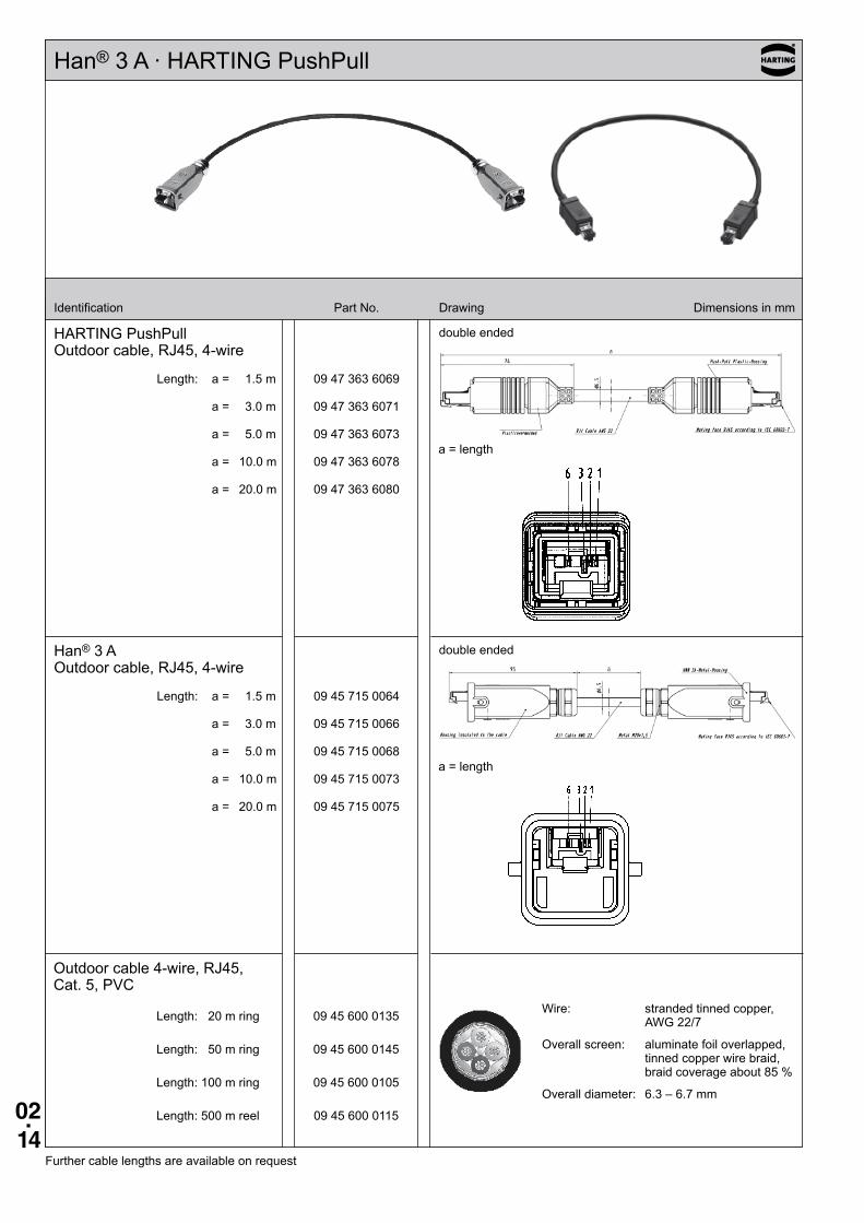
Han® 3 A · HARTING PushPull
Identification Part No. Drawing Dimensions in mm
HARTING PushPullOutdoor cable, RJ45, 4-wire
Length: a = 1.5 m 09 47 363 6069
a = 3.0 m 09 47 363 6071
a = 5.0 m 09 47 363 6073
a = 10.0 m 09 47 363 6078
a = 20.0 m 09 47 363 6080
Han® 3 AOutdoor cable, RJ45, 4-wire
Length: a = 1.5 m 09 45 715 0064
a = 3.0 m 09 45 715 0066
a = 5.0 m 09 45 715 0068
a = 10.0 m 09 45 715 0073
a = 20.0 m 09 45 715 0075
double ended
double ended
Further cable lengths are available on request
Outdoor cable 4-wire, RJ45, Cat. 5, PVC
Length: 20 m ring 09 45 600 0135
Length: 50 m ring 09 45 600 0145
Length: 100 m ring 09 45 600 0105
Length: 500 m reel 09 45 600 0115
Wire: stranded tinned copper, AWG 22/7
Overall screen: aluminate foil overlapped, tinned copper wire braid, braid coverage about 85 %
Overall diameter: 6.3 – 6.7 mm
a = length
a = length
02.15
Identification Part No. Drawing Dimensions in mm
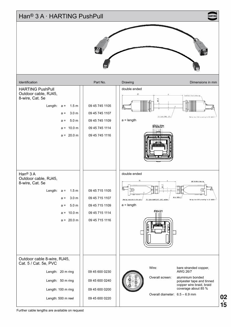
HARTING PushPullOutdoor cable, RJ45, 8-wire, Cat. 5e
Length: a = 1.5 m 09 45 745 1105
a = 3.0 m 09 45 745 1107
a = 5.0 m 09 45 745 1109
a = 10.0 m 09 45 745 1114
a = 20.0 m 09 45 745 1116
Han® 3 AOutdoor cable, RJ45, 8-wire, Cat. 5e
Length: a = 1.5 m 09 45 715 1105
a = 3.0 m 09 45 715 1107
a = 5.0 m 09 45 715 1109
a = 10.0 m 09 45 715 1114
a = 20.0 m 09 45 715 1116
double ended
double ended
Further cable lengths are available on request
Outdoor cable 8-wire, RJ45, Cat. 5 / Cat. 5e, PVC
Length: 20 m ring 09 45 600 0230
Length: 50 m ring 09 45 600 0240
Length: 100 m ring 09 45 600 0200
Length: 500 m reel 09 45 600 0220
a = length
a = length
Wire: bare stranded copper, AWG 26/7
Overall screen: aluminium bonded polyester tape and tinned copper wire braid, braid coverage about 85 %
Overall diameter: 6.5 – 6.9 mm
Han® 3 A · HARTING PushPull
02.16
Identification Part No. Drawing Dimensions in mm
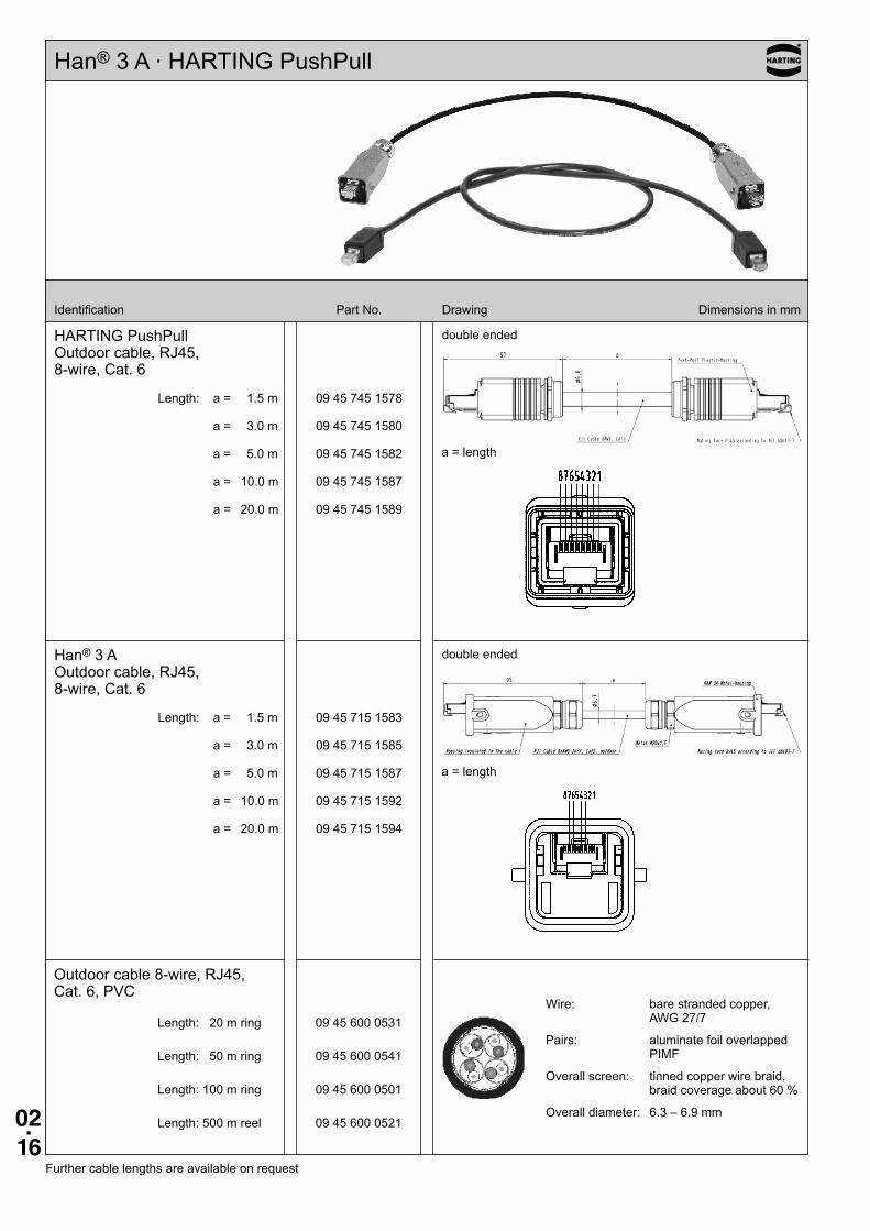
HARTING PushPullOutdoor cable, RJ45, 8-wire, Cat. 6
Length: a = 1.5 m 09 45 745 1578
a = 3.0 m 09 45 745 1580
a = 5.0 m 09 45 745 1582
a = 10.0 m 09 45 745 1587
a = 20.0 m 09 45 745 1589
Han® 3 AOutdoor cable, RJ45, 8-wire, Cat. 6
Length: a = 1.5 m 09 45 715 1583
a = 3.0 m 09 45 715 1585
a = 5.0 m 09 45 715 1587
a = 10.0 m 09 45 715 1592
a = 20.0 m 09 45 715 1594
double ended
double ended
Further cable lengths are available on request
Outdoor cable 8-wire, RJ45, Cat. 6, PVC
Length: 20 m ring 09 45 600 0531
Length: 50 m ring 09 45 600 0541
Length: 100 m ring 09 45 600 0501
Length: 500 m reel 09 45 600 0521
a = length
a = length
Wire: bare stranded copper, AWG 27/7
Pairs: aluminate foil overlapped PIMF
Overall screen: tinned copper wire braid, braid coverage about 60 %
Overall diameter: 6.3 – 6.9 mm
Han® 3 A · HARTING PushPull
02.17
Notes
Chapter 03 – Industrial Ethernet cable assemblies
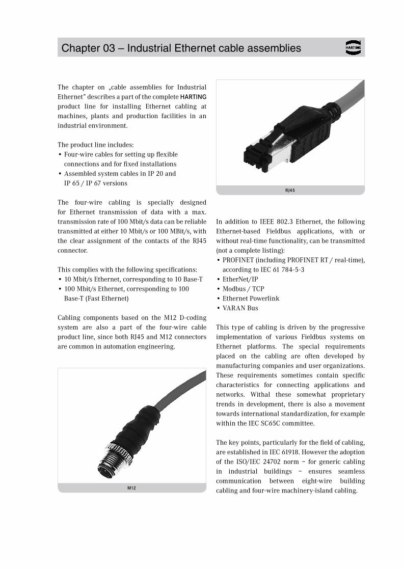
The chapter on „cable assemblies for Industrial Ethernet” describes a part of the complete HARTING product line for installing Ethernet cabling at machines, plants and production facilities in an industrial environment.
The product line includes:• Four-wire cables for setting up flexible
connections and for fixed installations• Assembled system cables in IP 20 and
IP 65 / IP 67 versions
The four-wire cabling is specially designed for Ethernet transmission of data with a max. transmission rate of 100 Mbit/s data can be reliable transmitted at either 10 Mbit/s or 100 MBit/s, with the clear assignment of the contacts of the RJ45 connector.
This complies with the following specifications:• 10 Mbit/s Ethernet, corresponding to 10 Base-T• 100 Mbit/s Ethernet, corresponding to 100
Base-T (Fast Ethernet)
Cabling components based on the M12 D-coding system are also a part of the four-wire cable product line, since both RJ45 and M12 connectors are common in automation engineering.
In addition to IEEE 802.3 Ethernet, the following Ethernet-based Fieldbus applications, with or without real-time functionality, can be transmitted (not a complete listing):• PROFINET (including PROFINET RT / real-time),
according to IEC 61 784-5-3• EtherNet/IP• Modbus / TCP• Ethernet Powerlink• VARAN Bus
This type of cabling is driven by the progressive implementation of various Fieldbus systems on Ethernet platforms. The special requirements placed on the cabling are often developed by manufacturing companies and user organizations. These requirements sometimes contain specific characteristics for connecting applications and networks. Withal these somewhat proprietary trends in development, there is also a movement towards international standardization, for example within the IEC SC65C committee.
The key points, particularly for the field of cabling, are established in IEC 61918. However the adoption of the ISO/IEC 24702 norm – for generic cabling in industrial buildings – ensures seamless communication between eight-wire building cabling and four-wire machinery-island cabling.M12
RJ45
03.01
Content Page
Chapter 03 – Industrial Ethernet cable assemblies
RJ45 . . . . . . . . . . . . . . . . . . . . . . . . . . . . . . . . . . . . . . . . . . . . . . . . . . . . . . . . . 03.02
M12 . . . . . . . . . . . . . . . . . . . . . . . . . . . . . . . . . . . . . . . . . . . . . . . . . . . . . . . . . . 03.06
03.02
RJ45
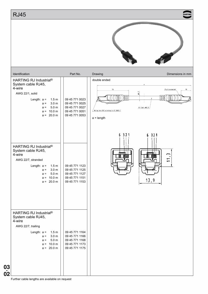
Identification Part No. Drawing Dimensions in mm
HARTING RJ Industrial® System cable RJ45, 4-wire
AWG 22/1, solid
Length: a = 1.5 m 09 45 771 0023 a = 3.0 m 09 45 771 0025 a = 5.0 m 09 45 771 0027 a = 10.0 m 09 45 771 0051 a = 20.0 m 09 45 771 0053
HARTING RJ Industrial® System cable RJ45, 4-wire
AWG 22/7, stranded
Length: a = 1.5 m 09 45 771 1123 a = 3.0 m 09 45 771 1125 a = 5.0 m 09 45 771 1127 a = 10.0 m 09 45 771 1151 a = 20.0 m 09 45 771 1153
HARTING RJ Industrial® System cable RJ45, 4-wire
AWG 22/7, trailing
Length: a = 1.5 m 09 45 771 1164 a = 3.0 m 09 45 771 1166 a = 5.0 m 09 45 771 1168 a = 10.0 m 09 45 771 1173 a = 20.0 m 09 45 771 1175
double ended
Further cable lengths are available on request
a = length
03.03
RJ45
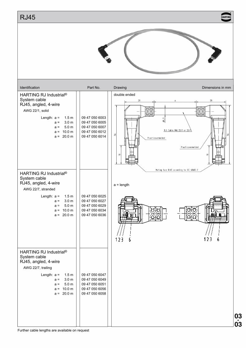
Identification Part No. Drawing Dimensions in mm
HARTING RJ Industrial® System cable RJ45, angled, 4-wire
AWG 22/1, solid
Length: a = 1.5 m 09 47 050 6003 a = 3.0 m 09 47 050 6005 a = 5.0 m 09 47 050 6007 a = 10.0 m 09 47 050 6012 a = 20.0 m 09 47 050 6014
HARTING RJ Industrial® System cable RJ45, angled, 4-wire
AWG 22/7, stranded
Length: a = 1.5 m 09 47 050 6025 a = 3.0 m 09 47 050 6027 a = 5.0 m 09 47 050 6029 a = 10.0 m 09 47 050 6034 a = 20.0 m 09 47 050 6036
HARTING RJ Industrial® System cable RJ45, angled, 4-wire
AWG 22/7, trailing
Length: a = 1.5 m 09 47 050 6047 a = 3.0 m 09 47 050 6049 a = 5.0 m 09 47 050 6051 a = 10.0 m 09 47 050 6056 a = 20.0 m 09 47 050 6058
double ended
Further cable lengths are available on request
a = length
03.04
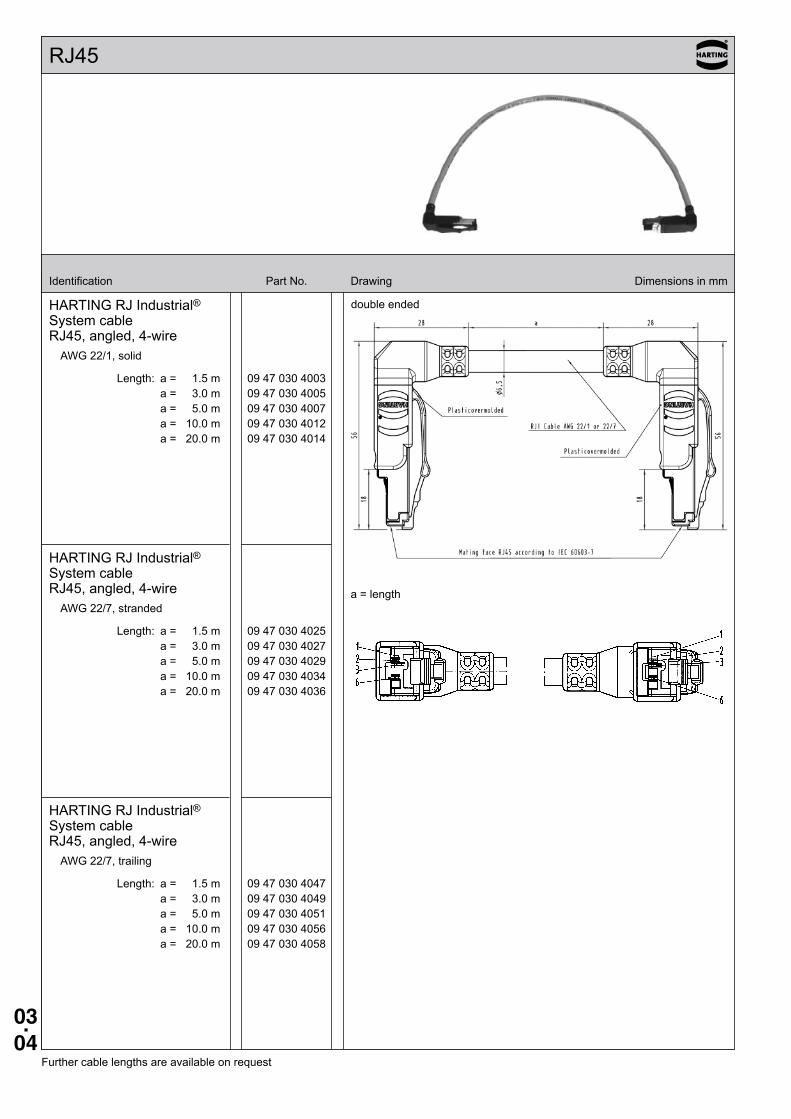
RJ45
Identification Part No. Drawing Dimensions in mm
HARTING RJ Industrial® System cable RJ45, angled, 4-wire
AWG 22/1, solid
Length: a = 1.5 m 09 47 030 4003 a = 3.0 m 09 47 030 4005 a = 5.0 m 09 47 030 4007 a = 10.0 m 09 47 030 4012 a = 20.0 m 09 47 030 4014
HARTING RJ Industrial® System cable RJ45, angled, 4-wire
AWG 22/7, stranded
Length: a = 1.5 m 09 47 030 4025 a = 3.0 m 09 47 030 4027 a = 5.0 m 09 47 030 4029 a = 10.0 m 09 47 030 4034 a = 20.0 m 09 47 030 4036
HARTING RJ Industrial® System cable RJ45, angled, 4-wire
AWG 22/7, trailing
Length: a = 1.5 m 09 47 030 4047 a = 3.0 m 09 47 030 4049 a = 5.0 m 09 47 030 4051 a = 10.0 m 09 47 030 4056 a = 20.0 m 09 47 030 4058
double ended
Further cable lengths are available on request
a = length
03.05
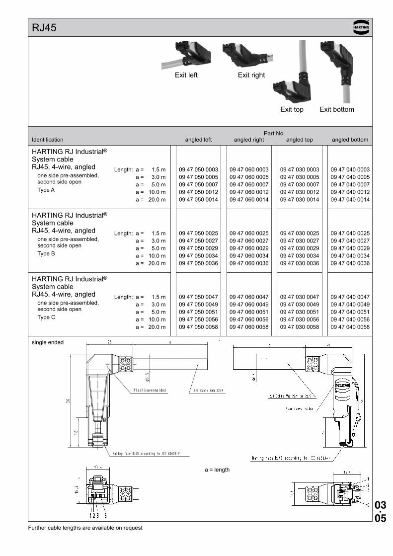
RJ45
Identification
HARTING RJ Industrial® System cable RJ45, 4-wire, angled
one side pre-assembled, second side openType A
Length: a = 1.5 m a = 3.0 m a = 5.0 m a = 10.0 m a = 20.0 m
Length: a = 1.5 m a = 3.0 m a = 5.0 m a = 10.0 m a = 20.0 m
Length: a = 1.5 m a = 3.0 m a = 5.0 m a = 10.0 m a = 20.0 m
HARTING RJ Industrial® System cable RJ45, 4-wire, angled
one side pre-assembled, second side openType B
HARTING RJ Industrial® System cable RJ45, 4-wire, angled
one side pre-assembled, second side openType C
single ended
Further cable lengths are available on request
a = length
Exit top
Exit rightExit left
Exit bottom
09 47 050 0003 09 47 060 0003 09 47 030 0003 09 47 040 0003 09 47 050 0005 09 47 060 0005 09 47 030 0005 09 47 040 0005 09 47 050 0007 09 47 060 0007 09 47 030 0007 09 47 040 0007 09 47 050 0012 09 47 060 0012 09 47 030 0012 09 47 040 0012 09 47 050 0014 09 47 060 0014 09 47 030 0014 09 47 040 0014
09 47 050 0025 09 47 060 0025 09 47 030 0025 09 47 040 0025 09 47 050 0027 09 47 060 0027 09 47 030 0027 09 47 040 0027 09 47 050 0029 09 47 060 0029 09 47 030 0029 09 47 040 0029 09 47 050 0034 09 47 060 0034 09 47 030 0034 09 47 040 0034 09 47 050 0036 09 47 060 0036 09 47 030 0036 09 47 040 0036
09 47 050 0047 09 47 060 0047 09 47 030 0047 09 47 040 0047 09 47 050 0049 09 47 060 0049 09 47 030 0049 09 47 040 0049 09 47 050 0051 09 47 060 0051 09 47 030 0051 09 47 040 0051 09 47 050 0056 09 47 060 0056 09 47 030 0056 09 47 040 0056 09 47 050 0058 09 47 060 0058 09 47 030 0058 09 47 040 0058
Part No. angled left angled right angled top angled bottom
03.06
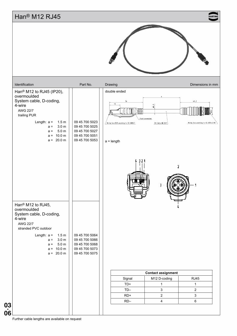
Han® M12 RJ45
Identification Part No. Drawing Dimensions in mm
Han® M12 to RJ45 (IP20), overmoulded System cable, D-coding, 4-wire
AWG 22/7 trailing PUR
Length: a = 1.5 m 09 45 700 5023 a = 3.0 m 09 45 700 5025 a = 5.0 m 09 45 700 5027 a = 10.0 m 09 45 700 5051 a = 20.0 m 09 45 700 5053
Han® M12 to RJ45, overmoulded System cable, D-coding, 4-wire
AWG 22/7 stranded PVC outdoor
Length: a = 1.5 m 09 45 700 5064 a = 3.0 m 09 45 700 5066 a = 5.0 m 09 45 700 5068 a = 10.0 m 09 45 700 5073 a = 20.0 m 09 45 700 5075
double ended
Further cable lengths are available on request
a = length
Contact assignmentSignal M12 D-coding RJ45
TD+ 1 1
TD– 3 2
RD+ 2 3
RD– 4 6
03.07
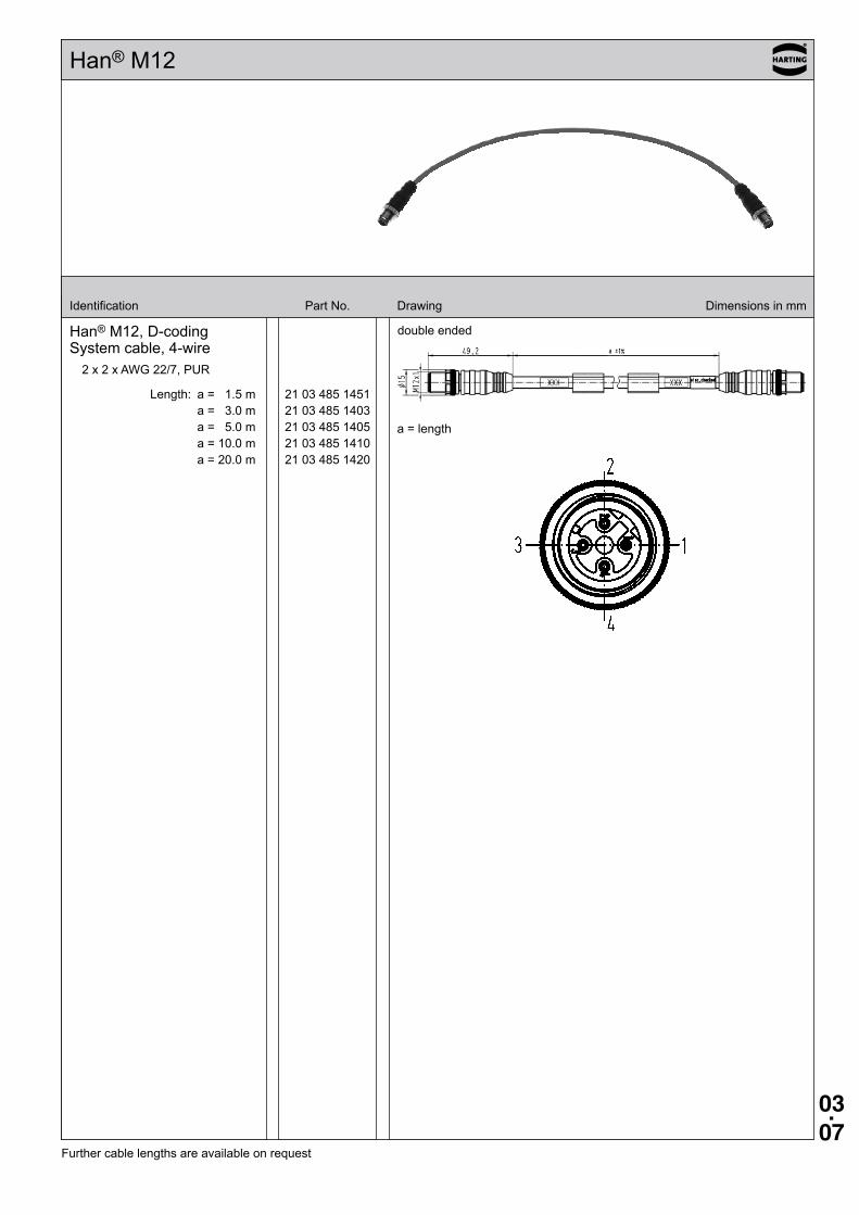
Han® M12
Identification Part No. Drawing Dimensions in mm
Han® M12, D-coding System cable, 4-wire
2 x 2 x AWG 22/7, PUR
Length: a = 1.5 m 21 03 485 1451 a = 3.0 m 21 03 485 1403 a = 5.0 m 21 03 485 1405 a = 10.0 m 21 03 485 1410 a = 20.0 m 21 03 485 1420
double ended
Further cable lengths are available on request
a = length
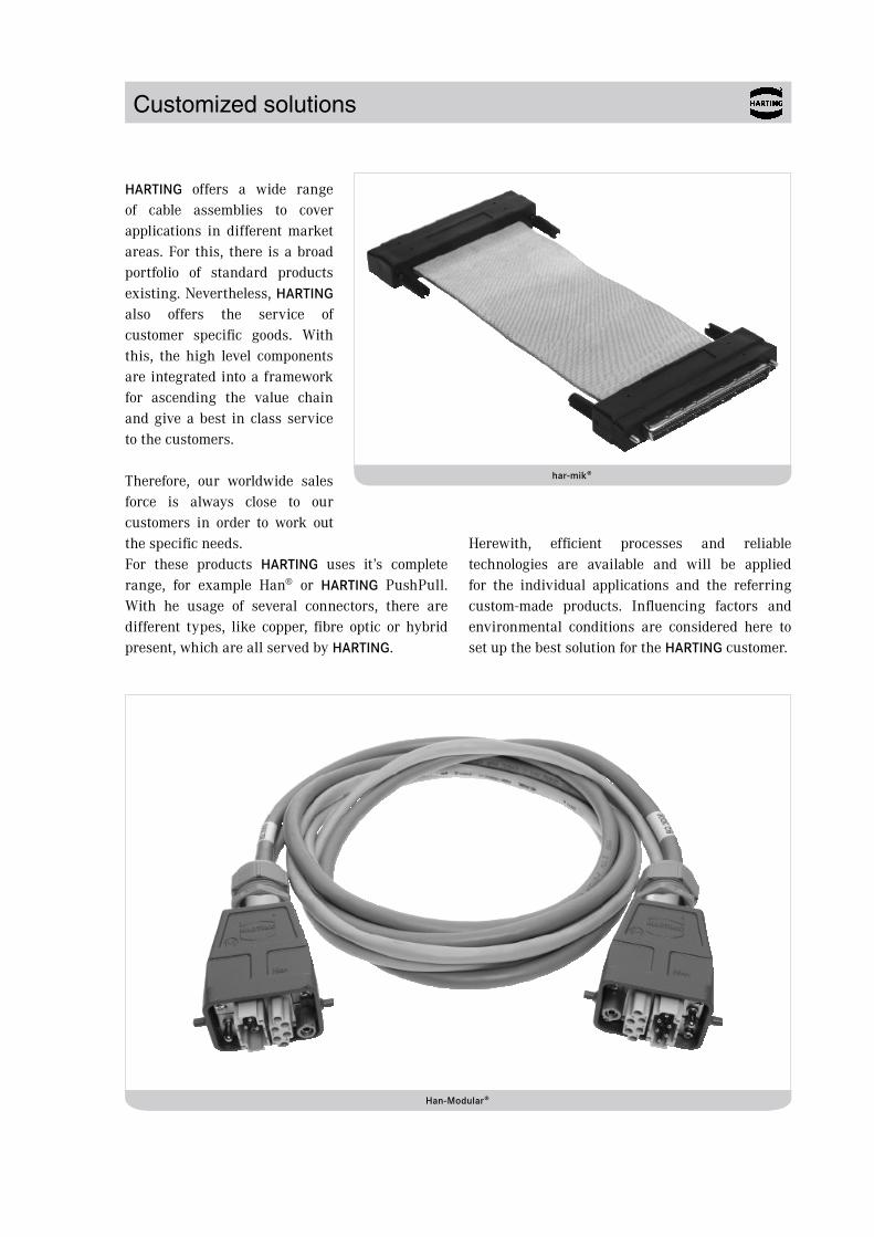
Customized solutions
HARTING offers a wide range of cable assemblies to cover applications in different market areas. For this, there is a broad portfolio of standard products existing. Nevertheless, HARTING also offers the service of customer specific goods. With this, the high level components are integrated into a framework for ascending the value chain and give a best in class service to the customers.
Therefore, our worldwide sales force is always close to our customers in order to work out the specific needs. For these products HARTING uses it’s complete range, for example Han® or HARTING PushPull. With he usage of several connectors, there are different types, like copper, fibre optic or hybrid present, which are all served by HARTING.
Herewith, efficient processes and reliable technologies are available and will be applied for the individual applications and the referring custom-made products. Influencing factors and environmental conditions are considered here to set up the best solution for the HARTING customer.
har-mik®
Han-Modular®
Customized solutions
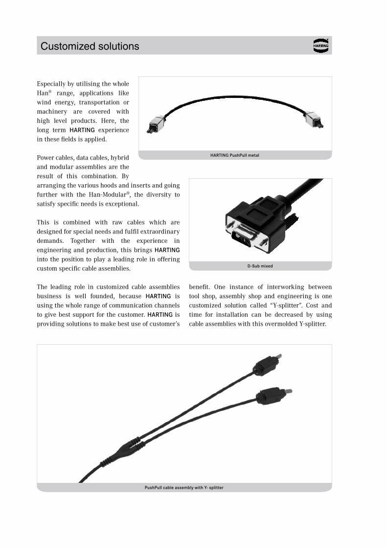
Especially by utilising the whole Han® range, applications like wind energy, transportation or machinery are covered with high level products. Here, the long term HARTING experience in these fields is applied.
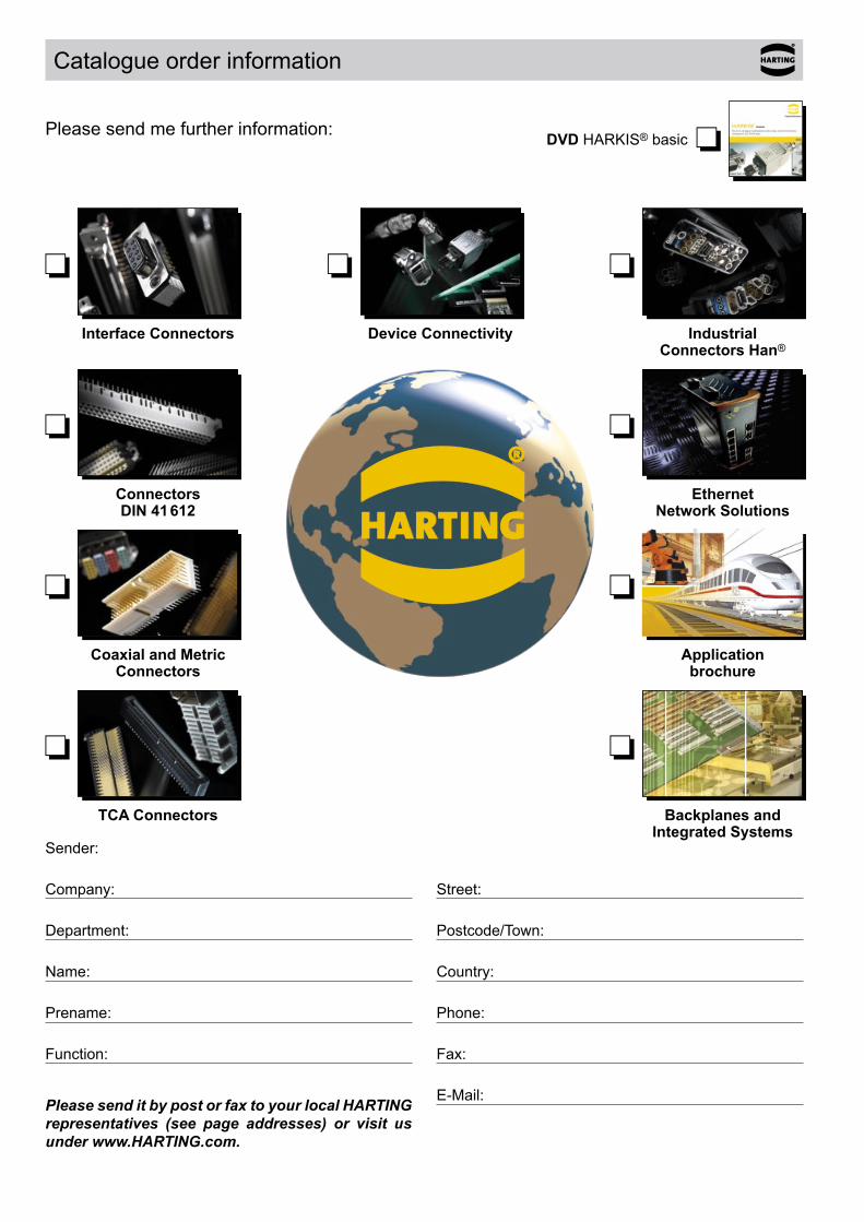
Power cables, data cables, hybrid and modular assemblies are the result of this combination. By arranging the various hoods and inserts and going further with the Han-Modular®, the diversity to satisfy specific needs is exceptional.
This is combined with raw cables which are designed for special needs and fulfil extraordinary demands. Together with the experience in engineering and production, this brings HARTING into the position to play a leading role in offering custom specific cable assemblies.
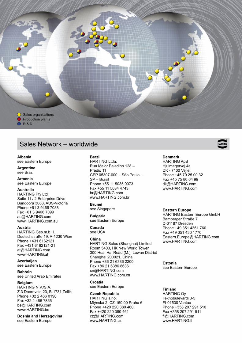
The leading role in customized cable assemblies business is well founded, because HARTING is using the whole range of communication channels to give best support for the customer. HARTING is providing solutions to make best use of customer’s
benefit. One instance of interworking between tool shop, assembly shop and engineering is one customized solution called “Y-splitter”. Cost and time for installation can be decreased by using cable assemblies with this overmolded Y-splitter.
HARTING PushPull metal
PushPull cable assembly with Y- splitter
D-Sub mixed
HARTING Interface Connectors
People | Power | Partnership
HARTING Industrial Connectors Han®
People | Power | Partnership
HARTING Coaxial and Metric Connectors
People | Power | Partnership
05 1
HARTING
Backplanes and Integrated Systems
People | Power | Partnership
HARTING Device Connectivity DeviceCon
People | Power | Partnership
HARTING
People | Power | Partnership
35 2
TCA Connectors
HARTING DIN 41 612
People | Power | Partnership
HARTING Technologies meet Markets
08_9761+9762_HA_Applikationsbros1 1 05.03.2008 12:05:45
DVD HARKIS® basic
Interface Connectors Industrial Connectors Han®
Connectors DIN 41 612
Ethernet Network Solutions
Coaxial and Metric Connectors
Application brochure
TCA Connectors Backplanes and Integrated Systems
Sender:
Company:
Department:
Name:
Prename:
Function:
Street:
Postcode/Town:
Country:
Phone:
Fax:
E-Mail:
Catalogue order information
Please send me further information:
Device Connectivity
Please send it by post or fax to your local HARTING representatives (see page addresses) or visit us under www.HARTING.com.
Sales organisationsProduction plantsR & D
Sales Network – worldwide
Albania see Eastern EuropeArgentina see BrazilArmenia see Eastern EuropeAustralia HARTING Pty Ltd Suite 11 / 2 Enterprise Drive Bundoora 3083, AUS-Victoria Phone +61 3 9466 7088 Fax +61 3 9466 7099 [email protected] www.HARTING.com.auAustria HARTING Ges.m.b.H. Deutschstraße 19, A-1230 Wien Phone +431 6162121 Fax +431 6162121-21 [email protected] www.HARTING.atAzerbaijan see Eastern EuropeBahrain see United Arab EmiratesBelgium HARTING N.V./S.A. Z.3 Doornveld 23, B-1731 Zellik Phone +32 2 466 0190 Fax +32 2 466 7855 [email protected] www.HARTING.beBosnia and Herzegovina see Eastern Europe
Brazil HARTING Ltda. Rua Major Paladino 128 – Prédio 11 CEP 05307-000 – São Paulo – SP – Brasil Phone +55 11 5035 0073 Fax +55 11 5034 4743 [email protected] www.HARTING.com.br
Brunei see Singapore
Bulgaria see Eastern Europe
Canada see USA
China HARTING Sales (Shanghai) Limited Room 5403, HK New World Tower 300 Huai Hai Road (M.), Luwan District Shanghai 200021, China Phone +86 21 6386 2200 Fax +86 21 6386 8636 [email protected] www.HARTING.com.cn
Croatia see Eastern Europe
Czech Republic HARTING s.r.o. Mlýnská 2, CZ-160 00 Praha 6 Phone +420 220 380 460 Fax +420 220 380 461 [email protected] www.HARTING.cz
Denmark HARTING ApS Hjulmagervej 4a DK - 7100 Vejle Phone +45 70 25 00 32 Fax +45 75 80 64 99 [email protected] www.HARTING.com
Eastern Europe HARTING Eastern Europe GmbH Bamberger Straße 7 D-01187 Dresden Phone +49 351 4361 760 Fax +49 351 436 1770 [email protected] www.HARTING.com
Estonia see Eastern Europe
Finland HARTING Oy Teknobulevardi 3-5 FI-01530 Vantaa Phone +358 207 291 510 Fax +358 207 291 511 [email protected] www.HARTING.fi
Sales Network – worldwide
France HARTING France 181 avenue des Nations, Paris Nord 2 BP 66058 Tremblay en France F-95972 Roissy Charles de Gaulle Cédex Phone +33 1 4938 3400 Fax +33 1 4863 2306 [email protected] www.HARTING.fr
Germany HARTING Deutschland GmbH & Co. KG P.O. Box 2451, D-32381 Minden Simeonscarré 1, D-32427 Minden Phone +49 571 8896 0 Fax +49 571 8896 282 [email protected] www.HARTING-Deutschland.de
Georgia see Eastern Europe
Great Britain HARTING Ltd., Caswell Road Brackmills Industrial Estate GB-Northampton, NN4 7PW Phone +44 1604 827 500 Fax +44 1604 706 777 [email protected] www.HARTING.co.uk
Hong Kong HARTING (HK) Limited Regional Office Asia Pacific 3512 Metroplaza Tower 1 223 Hing Fong Road Kwai Fong, N. T., Hong Kong Phone +852 2423 7338 Fax +852 2480 4378 [email protected] www.HARTING.com.hk
Hungary HARTING Magyarország Kft. Fehérvári út 89-95, H-1119 Budapest Phone +36 1 205 34 64 Fax +36 1 205 34 65 [email protected] www.HARTING.hu
India HARTING India Private Limited No. D, 4th Floor, ‚Doshi Towers‘ No. 156 Poonamallee High Road Kilpauk, Chennai 600 010 Tamil Nadu, India Phone +91 44 435604 15 / 416 Fax +91 44 435604 17 [email protected] www.HARTING.in
Indonesia see Malaysia
Israel COMTEL Israel Electronic Solutions Ltd. Bet Hapamon, 20 Hataas st. P.O.Box 66 Kefar-Saba 44425 Phone +972-9-7677240 Fax +972-9-7677243 [email protected] www.comtel.co.il
Italy HARTING SpA Via Dell' Industria 7 I-20090 Vimodrone (Milano) Phone +39 02 250801 Fax +39 02 2650 597 [email protected] www.HARTING.it
Japan HARTING K. K. Yusen Shin-Yokohama 1 Chome Bldg., 2F 1-7-9, Shin-Yokohama, Kohoku Yokohama 222-0033 Japan Phone +81 45 476 3456 Fax +81 45 476 3466 [email protected] www.HARTING.co.jp
Jordan see United Arab Emirates
Kazakhstan see Eastern Europe
Kirghizia see Eastern Europe
Korea (South) HARTING Korea Limited #308 Yatap Leaders Building 342-1, Yatap-dong, Bundang-gu Sungnam-City, Kyunggi-do 463-828, Republic of Korea Phone +82 31 781 4615 Fax +82 31 781 4616 [email protected] www.HARTING.kr
Kosovo see Eastern Europe
Kuwait see United Arab Emirates
Latvia see Eastern Europe
Lithuania see Eastern Europe
Macedonia see Eastern Europe
Malaysia (Office) HARTING Singapore Pte Ltd Malaysia Branch 11-02 Menara Amcorp Jln. Persiaran Barat 46200 PJ, Sel. D. E., Malaysia Phone +60 3 / 7955 6173 Fax +60 3 / 7955 5126 [email protected]
Montenegro see Eastern Europe
Netherlands HARTING B.V. Larenweg 44 NL-5234 KA 's-Hertogenbosch Postbus 3526 NL-5203 DM 's-Hertogenbosch Phone +31 736 410 404 Fax +31 736 440 699 [email protected] www.HARTINGbv.nl
New Zealand see Australia
Norway HARTING A/S Østensjøveien 36, N-0667 Oslo Phone +47 22 700 555 Fax +47 22 700 570 [email protected] www.HARTING.no
Pakistan see United Arab Emirates
Philippines see Malaysia
Poland HARTING Polska Sp. z o. o ul. Kamieńskiego 201-219 PL-51-126 Wrocław Phone +48 71 352 81 71 Fax +48 71 320 74 44 [email protected] www.HARTING.pl
Portugal HARTING Iberia, S. A. Avda. Josep Tarradellas 20-30 4o 6a E-08029 Barcelona Phone +351 219 673 177 Fax +351 219 678 457 [email protected] www.HARTING.es/pt
Qatar see United Arab Emirates
Republic of Moldova see Eastern Europe
Sales Network – worldwide
Romania HARTING Romania SCS Europa Unita str. 21 550018-Sibiu, Romania Phone +40 369-102 671 Fax +40 369-102 622 [email protected] www.HARTING.com
Russia HARTING ZAO Maliy Sampsoniyevsky prospect 2A 194044 Saint Petersburg, Russia Phone +7 812 327 6477 Fax +7 812 327 6478 [email protected] www.HARTING.ru
Saudi Arabia see United Arab Emirates
Serbia see Eastern Europe
Singapore HARTING Singapore Pte Ltd. 25 International Business Park #02-06 German Centre Singapore 609916 Phone +65 6225 5285 Fax +65 6225 9947 [email protected] www.HARTING.sg
Slovakia HARTING s.r.o. Sales office Slovakia J. Simora 5, SK - 940 52 Nové Zámky Phone +421 356-493 993 Fax +421 356-402 114 [email protected] www.HARTING.sk
Slovenia see Eastern Europe
South Africa Cabcon Technologies (PTY) Ltd P.O. Box 13002, Northmead, 1511 Phone +27 1184533258 Fax +27 118454077 [email protected]
Spain HARTING Iberia S.A. Avda. Josep Tarradellas 20-30 4o 6a E-08029 Barcelona Phone +34 93 363 84 75 Fax +34 93 419 95 85 [email protected] www.HARTING.es
Sweden HARTING AB Gustavslundsvägen 141 B 4tr S-167 51 Bromma Phone +46 8 445 7171 Fax +46 8 445 7170 [email protected] www.HARTING.se
Switzerland HARTING AG Industriestrasse 26 CH-8604 Volketswil Phone +41 44 908 20 60 Fax +41 44 908 20 69 [email protected] www.HARTING.ch
Taiwan HARTING Taiwan Ltd. Room 1, 5/F 495 GuangFu South Road RC-110 Taipei, Taiwan Phone +886 2 2758 6177 Fax +886 2 2758 7177 [email protected] www.HARTING.com.tw
Tajikistan see Eastern Europe
Thailand see Malaysia
Turkey HARTING TURKEI Elektronik Ltd. Şti. Barbaros Mah. Dereboyu Cad. Fesleğen Sok. Uphill Towers, A-1b Kat:8 D:45 34746 Ataşehir, İstanbul Phone +90 216 688 81 00 Fax +90 216 688 81 01 [email protected] www.HARTING.com.tr
Turkmenistan see Eastern Europe
United Arab Emirates Eurotech Fzc Office Bldg-36, Office No. G36-02 P.O. Box 49602 Hamriyah Free Zone, Sharjah Phone +971 6 5262077 Fax +971 6 5262117 [email protected] www.eurotech.ae
Ukraine see Eastern Europe
USA HARTING Inc. of North America 1370 Bowes Road USA-Elgin, Illinois 60123 Phone +1 (877) 741-1500 (toll free) Fax +1 (866) 278-0307 (Inside Sales) [email protected] www.HARTING-USA.com
Uzbekistan see Eastern Europe
Distributors – worldwide
Farnell: www.farnell.com
RS Components: www.rs-components.com
FUTURE Electronics: www.futureelectronics.com
Other countries and general contact
HARTING Electronics GmbH & Co. KG P.O. Box 1433 32328 Espelkamp - Germany Phone +49 5772/47-97200 Fax +49 5772/47-777 [email protected]
It is the customer's responsibility to check whether the components illustrated in this catalogue also comply with different regulations from those stated in special fields of applications.
We reserve the right to modify designs or substance of content in order to improve quality, keep pace with technological advancement or meet particular requirements in production.
No part of this catalogue may be reproduced in any form (print, photocopy, microfilm or any other process) or processed, duplicated or distributed by means of electronic systems without the prior written consent of HARTING Electronics GmbH & Co. KG, Espelkamp. We are bound by the English version only.
© HARTING Electronics GmbH & Co. KG, Espelkamp – All rights reserved, including those of the translation.
General information

www.HARTING.com
MO
/21
.09.
11/
2.0
98
32
005
0201