Embed Size (px)
Citation preview
Hartmut F.-W. Sadrozinski, SCIPP
Beam Test for Proton Computed Tomography PCT
Loma Linda University Medical Center
Hartmut F.-W. Sadrozinski
Santa Cruz Inst. for Particle Physics SCIPP
UCSC Santa Cruz Institute of
Particle Physics
Florence & Catania
(aka Mapping out “The Banana”)
• The pCT Project
• Most likely Path MLP
• Beam Test Set-up
• Comparison with MLP
• Localization Accuracy

Hartmut F.-W. Sadrozinski, SCIPP
Authors
Loma Linda UMCReinhartd Schulte, MDVladimir Bashkirov, PhDGeorge Coutrakon, PhDPeter Koss, MS
Santa Cruz Institute for Particle PhysicsHartmut Sadrozinski, PhDAbe Seiden, PhDDavid C Williams, PhDJason Feldt (grad. Student) Jason Heimann (undergrad student)Dominic Lucia (undergrad student)Nate Blumenkrantz (undergrad student)Eric Scott (undergrad student)
Florence U.
Mara Bruzzi, PhD
David Menichelli, PhD
Monica Scaringella (grad student)
INFN Catania
Pablo Cirrone, PhD
Giacomo Cuttone, PhD
Nunzio Randazzo, PhD
Domenico Lo Presti, Engineer
Valeria Sipali (grad student)
Hartmut F.-W. Sadrozinski, SCIPP
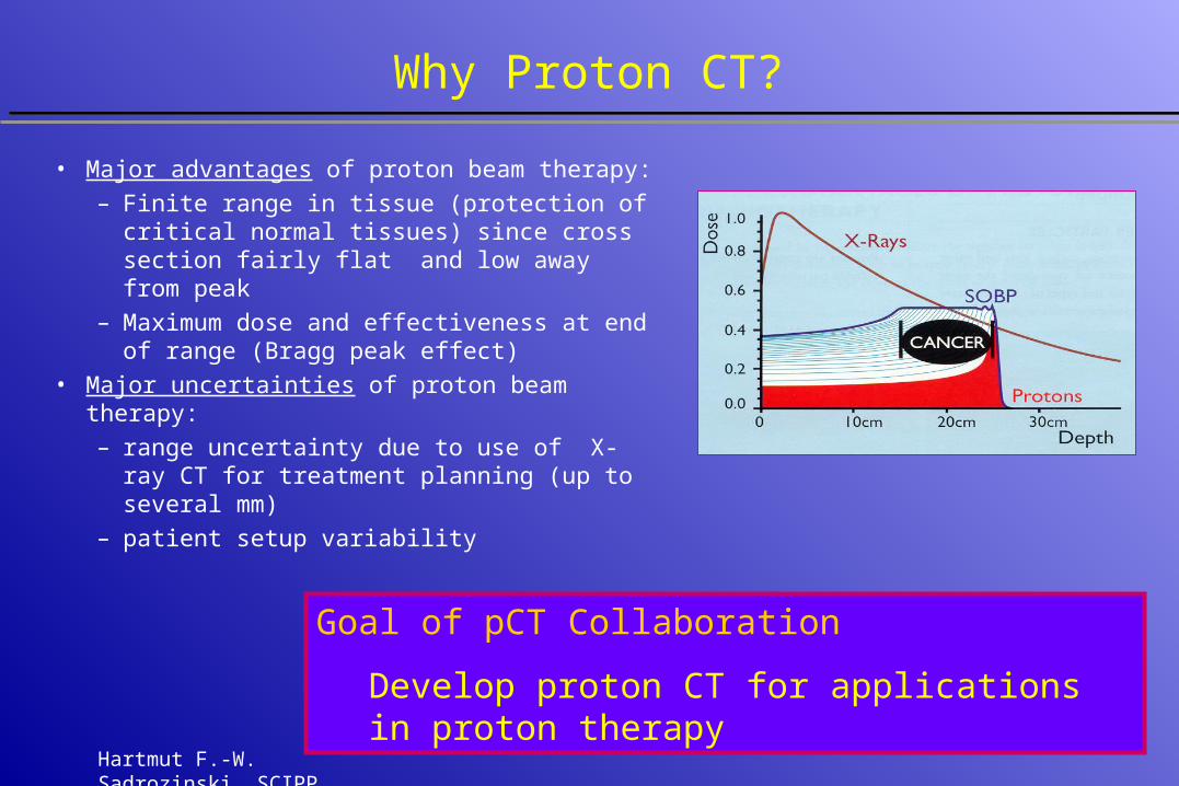
Why Proton CT?
• Major advantages of proton beam therapy:
– Finite range in tissue (protection of critical normal tissues) since cross section fairly flat and low away from peak
– Maximum dose and effectiveness at end of range (Bragg peak effect)
• Major uncertainties of proton beam therapy:
– range uncertainty due to use of X-ray CT for treatment planning (up to several mm)
– patient setup variability
Goal of pCT Collaboration
Develop proton CT for applications in proton therapy
Hartmut F.-W. Sadrozinski, SCIPP
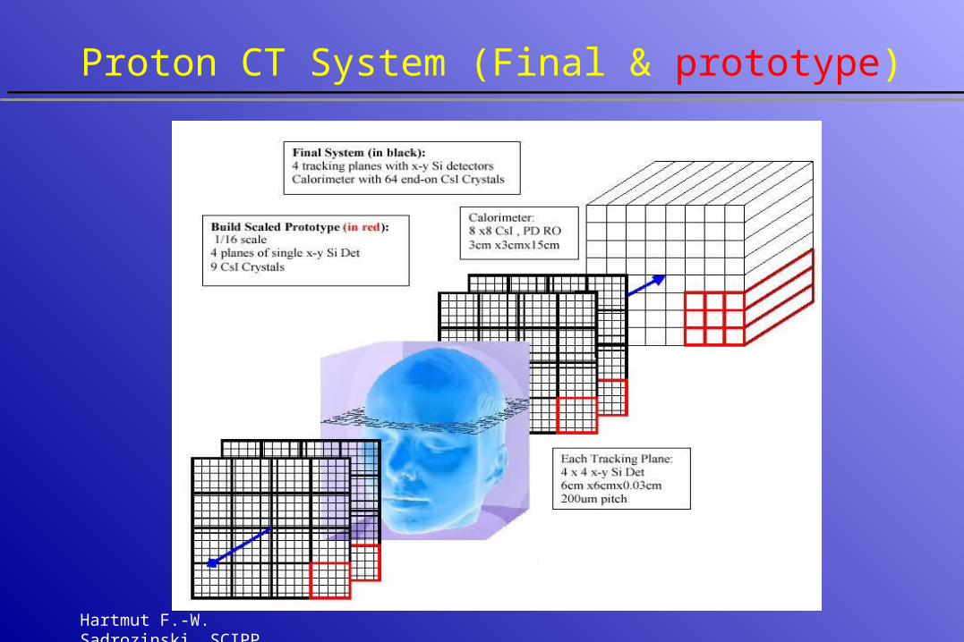
Proton CT System (Final & prototype)

Hartmut F.-W. Sadrozinski, SCIPP
Comparison pCT - X-ray CT
52
2
~ Dd
E
b
a
Hartmut F.-W. Sadrozinski, SCIPP
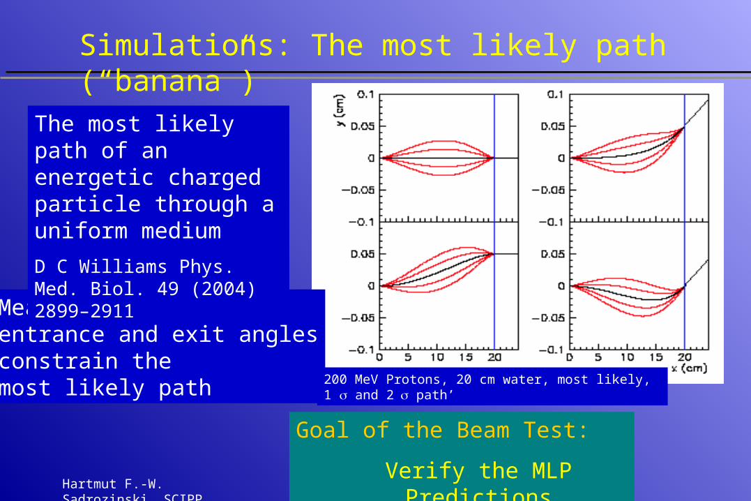
Simulations: The most likely path (“banana”)
Measurement of entrance and exit anglesconstrain the most likely path
The most likely path of an energetic charged particle through a uniform medium
D C Williams Phys. Med. Biol. 49 (2004) 2899–2911
200 MeV Protons, 20 cm water, most likely, 1 and 2 path’
Goal of the Beam Test:
Verify the MLP Predictions
Hartmut F.-W. Sadrozinski, SCIPP
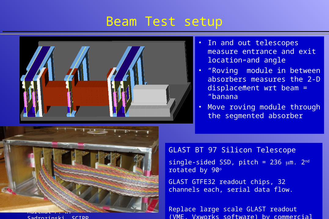
Beam Test setup
• In and out telescopes measure entrance and exit location and angle
• “Roving” module in between absorbers measures the 2-D displacement wrt beam = “banana”
• Move roving module through the segmented absorber
GLAST BT 97 Silicon Telescope
single-sided SSD, pitch = 236 m. 2nd rotated by 90o
GLAST GTFE32 readout chips, 32 channels each, serial data flow.
Replace large scale GLAST readout (VME, Vxworks software) by commercial FPGA and NI 6534 PCI card
Hartmut F.-W. Sadrozinski, SCIPP
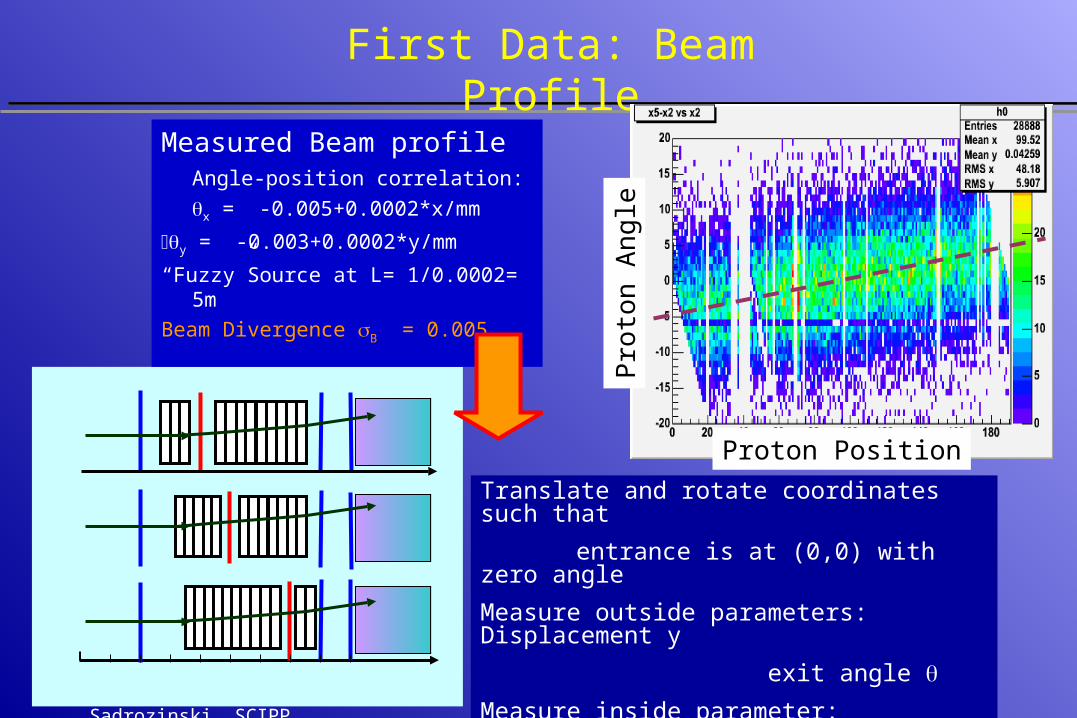
First Data: Beam Profile
Measured Beam profileAngle-position correlation:
x = -0.005+0.0002*x/mm
y = -0.003+0.0002*y/mm
“Fuzzy”Source at L= 1/0.0002= 5m
Beam Divergence B = 0.005
Translate and rotate coordinates such that
entrance is at (0,0) with zero angle
Measure outside parameters: Displacement y
exit angle
Measure inside parameter: Displacement yl
in roving module vs. absorber depth
Pro
ton
Ang
le
Proton Position
Hartmut F.-W. Sadrozinski, SCIPP
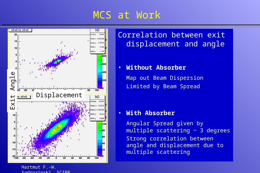
MCS at Work
Correlation between exit displacement and angle
• Without Absorber
Map out Beam Dispersion
Limited by Beam Spread
• With Absorber
Angular Spread given by multiple scattering ~ 3 degrees
Strong correlation between angle and displacement due to multiple scattering
Displacement
Exi
t Ang
le
Hartmut F.-W. Sadrozinski, SCIPP
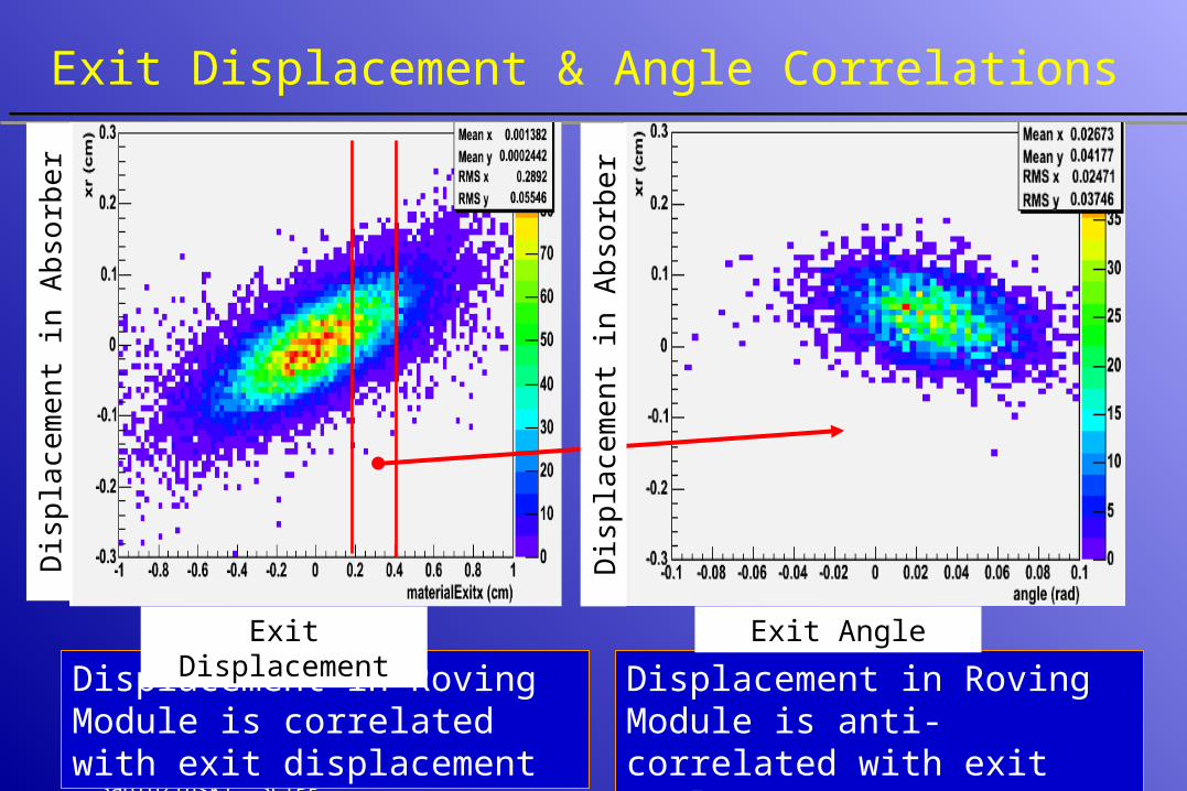
Exit Displacement & Angle Correlations
Displacement in Roving Module is correlated with exit displacement Y
Displacement in Roving Module is anti-correlated with exit angle blue:
Dis
plac
emen
t in
Abs
orbe
r
Dis
plac
emen
t in
Abs
orbe
rExit Displacement Exit Angle
Hartmut F.-W. Sadrozinski, SCIPP
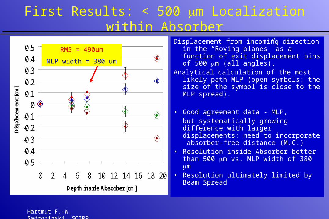
First Results: < 500 m Localization within Absorber
Displacement from incoming direction in the “Roving planes” as a function of exit displacement bins of 500 m (all angles).
Analytical calculation of the most likely path MLP (open symbols: the size of the symbol is close to the MLP spread).
• Good agreement data - MLP, but systematically growing difference with larger displacements: need to incorporate absorber-free distance (M.C.)
• Resolution inside Absorber better than 500 m vs. MLP width of 380 m
• Resolution ultimately limited by Beam Spread
-0.5-0.4-0.3-0.2-0.1
00.10.20.30.40.5
0 2 4 6 8 10 12 14 16 18 20
Depth inside Absorber [cm]
Dis
plac
emen
t [cm
]
RMS = 490um
MLP width = 380 um
Hartmut F.-W. Sadrozinski, SCIPP
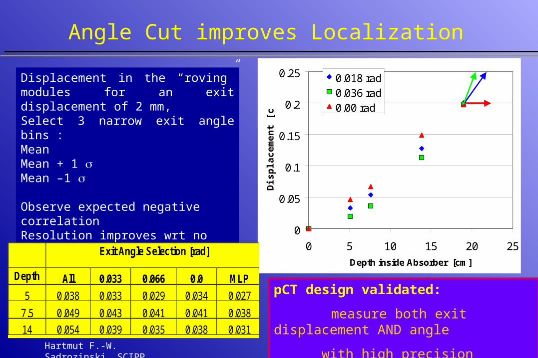
Angle Cut improves Localization
0
0.05
0.1
0.15
0.2
0.25
0 5 10 15 20 25
Depth inside Absorber [cm]D
isp
lace
men
t [c
m]
0.018 rad0.036 rad0.00 rad
Displacement in the “roving” modules for an exit displacement of 2 mm, Select 3 narrow exit angle bins :Mean Mean + 1 Mean –1
Observe expected negative correlationResolution improves wrt no angle selection
pCT design validated: measure
Exit Angle Selection [rad]
Depth All 0.033 0.066 0.0 MLP
5 0.038 0.033 0.029 0.034 0.027
7.5 0.049 0.043 0.041 0.041 0.038
14 0.054 0.039 0.035 0.038 0.031
pCT design validated:
measure both exit displacement AND angle
with high precision
Hartmut F.-W. Sadrozinski, SCIPP
pCT Beam Test Conclusions
• Si tracker affords high resolution position and angle measurement• First results show localization within phantom to better than 400 um• Simple analysis confirms prediction of MLP on the < 200 um level
(improvement expected when air gaps are included)• Data await detailed comparison with simulations using GEANT4 and
analytical “banana” (INFN, SLAC and Japanese Geant4 groups)------>Poster J03-25
• Improvements for Tracker: – Reduce absorber-less gap around “roving module”– Increased precision of input parameters (entrance angle) needed to correct for
beam divergence
• Next step: image NON-uniform density phantom using the energy loss measurement in the calorimeter