Embed Size (px)
Citation preview

HAW-ArduinoSensors and Arduino
14.10.2010 © F. Schubert HAW - Arduino 1
Content of the USB-Stick
• PDF-File of this script
• Arduino-software
• Source-codes
• Helpful links
14.10.2010 HAW - Arduino 2

Report for the Tasks
• Description
• Datasheets
• Schematics
• Calculations
• Source-codes with comments
• Documentation of the results
14.10.2010 HAW - Arduino 3

First Steps
• Introduction• Hardware and software• Installation of the environment• The first Arduino-program• Inputs and outputs• Voltmeter• Thermometer• Piezo sensor• Servo-motor
14.10.2010 HAW - Arduino 4
The Hardware
• HAW-Arduino USB-Board• Breadboard small• Breadboard big• USB cable• Piezo-buzzer• Potentiometer• Switches• LEDs• Transistor• Resistors• Photoresistor• Photodiode
• LCD-module• NTC• Operational amplifier• Comparator• Wires• Cables• Soldering equipment• Socket strips• Connectors• Experimentation board• Relay• IR-transmitter
14.10.2010 HAW - Arduino 5

What means Arduino?
Hardware Programming-software Community
14.10.2010 HAW - Arduino 6

Hardware
• Cheap, fast and open
• AVR ATmega 168 (328) Microcontroller
• C-Programming
• Programming via USB
• Power supply via USB or external
14.10.2010 HAW - Arduino 7

Arduino Characteristics
• 16 kByte EEPROM
• 1 kByte RAM
• 16 MHz Clock
• Inputs and Outputs
– 14 digital Inputs/Outputs
– 6 analog Inputs
– 6 PWM-Outputs
– I2C-Bus, serial Bus (TX/RX)
14.10.2010 HAW - Arduino 8

Arduino Duemilanove Board
14.10.2010 HAW - Arduino 9
Digital Inputs and Outputs
Analog Inputs
USB Connector
LED at Pin 13
Power LED
Microcontroller
TX / RX LEDs
External Power Supply
Reset Button
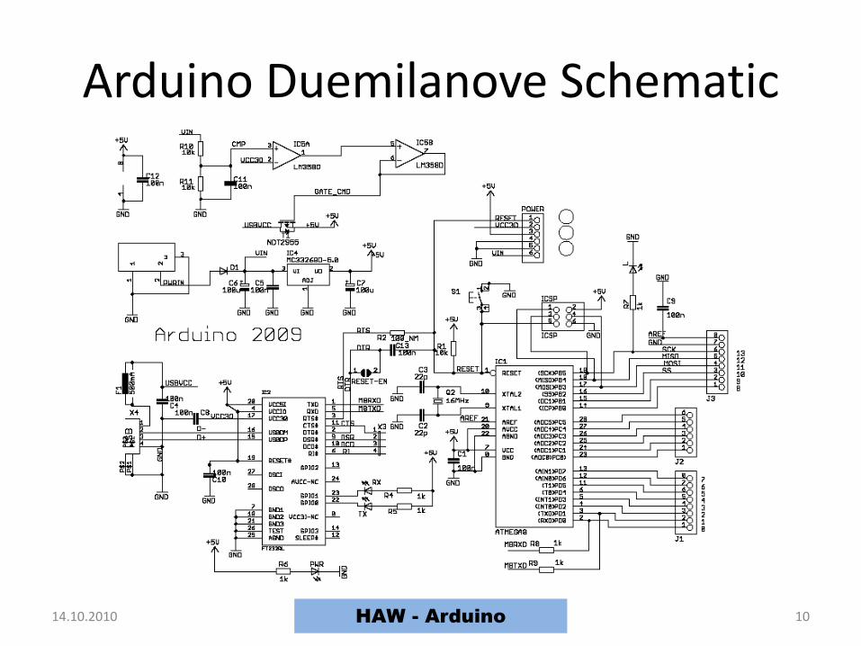
Arduino Duemilanove Schematic
14.10.2010 HAW - Arduino 10

Arduino-Software
14.10.2010 HAW - Arduino 11
Verify
(Compile)
Stop
New
Open
Save
Serial Monitor
ON
Status Field
Status Messages
Upload to
I/O Board

Installation
• Unzip of the Arduino-software
• Connection of the Arduino-board
• Installation of the drivers (administrator rightsneeded)
• Reboot the computer
• Run the Arduino-software
• Go on……..
14.10.2010 HAW - Arduino 12

Unzip the Arduino-Softwae
14.10.2010 HAW - Arduino 13

Connection of the Arduino-Board
14.10.2010 HAW - Arduino 14
Power LED is on
LED at Pin 13 blinks
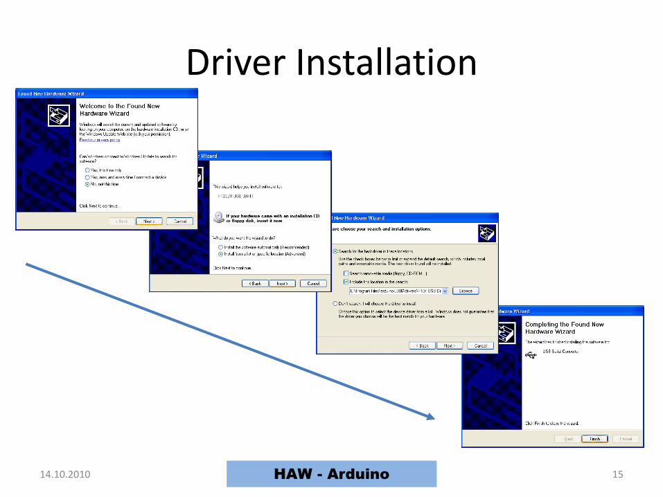
Driver Installation
14.10.2010 HAW - Arduino 15

Selecting the COM-Port
14.10.2010 HAW - Arduino 16

Selecting the Board
14.10.2010 HAW - Arduino 17

Status-Messages
14.10.2010 HAW - Arduino 18
Upload done
Wrong serial port
Wrong board

Troubleshooting
• Press the reset-button on
Arduino and try again
• Check the serial port (Connection andnumber)
• Read the red text (Debugging output) at thebottom to determine the problem
• The status area shows what is wrong
14.10.2010 HAW - Arduino 19

UPLOAD
COMPILEUPLOAD
Cycle of Development
14.10.2010 HAW - Arduino 20
EDIT
COMPILE
UPLOAD
RUN
ERROR ?
ERROR ?
ERROR ?
YES
YESYES
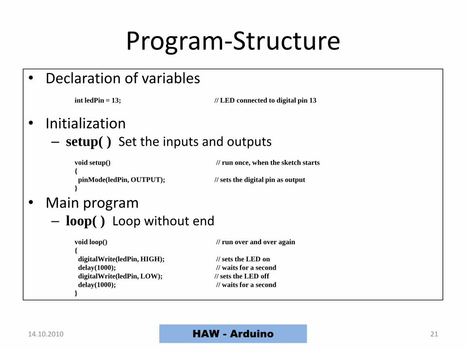
Program-Structure• Declaration of variables
int ledPin = 13; // LED connected to digital pin 13
• Initialization– setup( ) Set the inputs and outputs
void setup() // run once, when the sketch starts
pinMode(ledPin, OUTPUT); // sets the digital pin as output
• Main program– loop( ) Loop without end
void loop() // run over and over again
digitalWrite(ledPin, HIGH); // sets the LED on
delay(1000); // waits for a second
digitalWrite(ledPin, LOW); // sets the LED off
delay(1000); // waits for a second
14.10.2010 HAW - Arduino 21

The blinking LED
14.10.2010 HAW - Arduino 22

Program Examples
14.10.2010 HAW - Arduino 23

Hardware
14.10.2010 HAW - Arduino 24
HAW-Arduino Small Breadboard Big Breadboard

Solderless Breadboard
14.10.2010 HAW - Arduino 25
All connectedNot connected Group of 5 connectedAll connected
HAW - Arduino
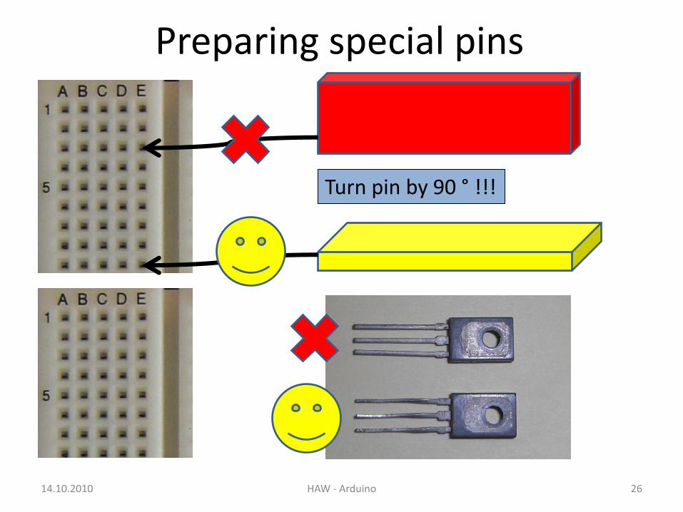
Preparing special pins
14.10.2010 HAW - Arduino 26
Turn pin by 90 ° !!!

Hardware-Box
14.10.2010 HAW - Arduino 27
LEDsIR-Transmit.IR-Receiver
SwitchesPots
RelayBD139LM311TL072
1N4001
BuzzerPiezo-Ele.
Photo-Res.NTC
Resistors
DC-MotorBattery
Battery-Clip
CablesWires

Hardware
14.10.2010 HAW - Arduino 28

Hardware
14.10.2010 HAW - Arduino 29

Power Supply• From USB (Current is limited to 500 mA)
• External power supply (Duemilanove switchesautomatically) (VIN and GND or power jack)
SMPS Battery
14.10.2010 HAW - Arduino 30HAW - Arduino
Diecimila
Jumper to EXT

Rules for the Development
• First draw the circuit
• Program the Arduino before you connect theinputs and outputs!
• If you have different power supplies connect thedifferent GNDs if necessary
• Connect and test the circuit on the solderlessboard before you connect it to the Arduino
• Connect the power supplies when the circuit iscomplete and tested
14.10.2010 HAW - Arduino 31

Digital I/O pinmode(pin, mode) - initializationdigitalWrite(pin, value) int digitalRead(pin)
Analog I/OanalogReference(type) - initializationint analogRead(pin) analogWrite(pin, value) - PWM
14.10.2010 32
Digital and Analog Input/Output
HAW - Arduino

Digital Output
• Make an external LED at pin 6 blinking
• Write a program for a traffic light with 3 LEDs
14.10.2010 33
Pin 6
Arduino Board
VCC
GND
(from USB)
220 Ω
Pin 5
Arduino Board
VCC
GND
(from USB)
Pin 4
Pin 6
HAW - Arduino

Digital Input
• A digital input floats between 0 and 5 V, if it isnot connected
• A resistor pulls an input to 5V (pull up) or toGND (pull down)
• Using a pullup-resistor the switch pushes theinput to GND
• Using a pulldown-resistor the switch pushesthe input to 5 V
14.10.2010 34HAW - Arduino
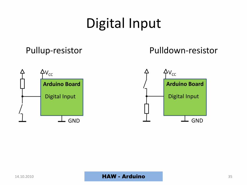
Digital Input
14.10.2010 35HAW - Arduino
Arduino Board
VCC
GND
Digital Input
Pullup-resistor Pulldown-resistor
Arduino Board
VCC
GND
Digital Input

Tasks for Digital Input
• Connect a switch to pin 2 of the Arduino
• The switch controls the function of the trafficlight:
High: Normal function
Low: Yellow light blinking
14.10.2010 36HAW - Arduino
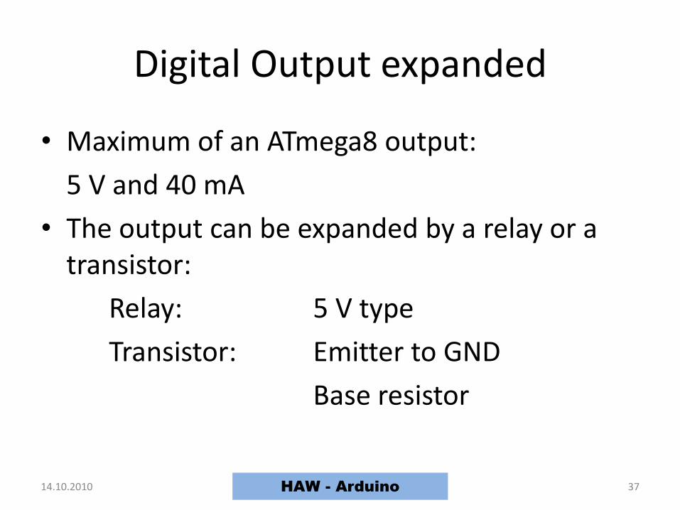
Digital Output expanded
• Maximum of an ATmega8 output:
5 V and 40 mA
• The output can be expanded by a relay or a transistor:
Relay: 5 V type
Transistor: Emitter to GND
Base resistor
14.10.2010 37HAW - Arduino

Tasks for Digital Output expanded
• Connect the 12 V motor to pin 6 of the Arduinofirst over a relay and then over a npn-transistor(BD 139).
• For the motor use an external supply voltage(don´t forget to connect the different GNDs!).
• Switch the motor on and off by a switch at pin 11 of the Arduino.
• The base resistor of the transistor is 1 kΩ.• Protect the Arduino and the transistor by a
protective diode!
14.10.2010 38HAW - Arduino
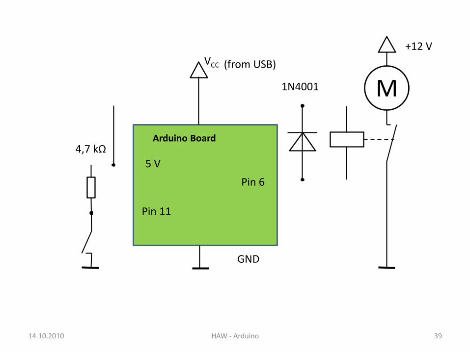
14.10.2010 HAW - Arduino 39
Pin 6
Arduino Board
VCC
GND
(from USB)
M
+12 V
Pin 11
5 V
1N4001
4,7 kΩ

14.10.2010 HAW - Arduino 40
Pin 6
Arduino Board
VCC
GND
(from USB)
1 kΩ
M
+12 V
Pin 11
5 V
1N4001
BD139
4,7 kΩ

PWM Output
• Pulse Width Modulation
• Characteristics:
Pulse width range
Pulse period
Voltage levels
• Average is like an analog voltage UAV
UAV = width/period *(HIGH – LOW) + LOW
• For PWM use the analogWrite() instruction
14.10.2010 41
width
period
level
LOW
HIGH
HAW - Arduino

Analog Input
• The ATmega 168 has 6 ADC inputs
• The maximum input range
is from 0 V to 5 V
• The resolution is 10 bit
(1024 values)
• The reference voltage is variable
14.10.2010 42HAW - Arduino

The ADC of the Arduino
14.10.2010 HAW - Arduino 43
• Determine the function: SerialOut = f(UIN, UREF)
• 0 ≤ UIN ≤ UREF
• UREF : 1.1 V, 3.3 V and 5 V
analogReference(type)DescriptionConfigures the reference voltage used for analog input. The analogRead() function will return 1023 for an input equal to the reference voltage. The options are: DEFAULT: the default analog reference of 5 volts. INTERNAL: an built-in reference, equal to 1.1 volts on the ATmega168 and 2.56 volts on the ATmega8. EXTERNAL: the voltage applied to the AREF pin is used as the reference. Parameterstype: which type of reference to use (DEFAULT, INTERNAL, or EXTERNAL).

External UREF
14.10.2010 44
4,7 KΩ
3,3 V
HAW - Arduino

Characteristics of the Voltmeter
• High-impedance input
• Input-range: -5 V to + 5 V
• UREF = 5 V
• Output on LCD :
14.10.2010 HAW - Arduino 45
+ 2 . 7 3 V V- 8 7 6 m

LCD
Blockdiagram of the Voltmeter
14.10.2010 HAW - Arduino 46
Pre-Amp ArduinoUIN
HAW - Arduino

Pre-Amplifier (Level-Shifter)
14.10.2010 HAW - Arduino 47

Calculation of the PreAmp
14.10.2010 48HAW - Arduino

Pre-Amplifier (Level-Shifter)
14.10.2010 HAW - Arduino 49

Protection Circuit
14.10.2010 HAW - Arduino 50
Arduino Board
UOUT BAT 85
5 V
1 KΩ BAT 85
470 nF
Pin 2
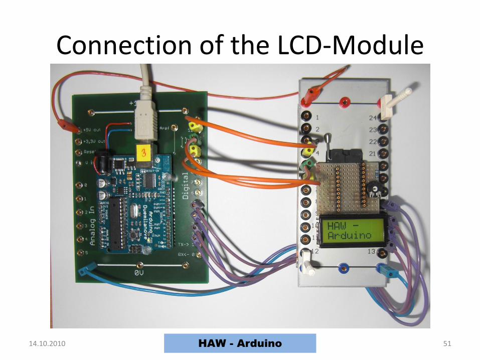
Connection of the LCD-Module
14.10.2010 HAW - Arduino 51
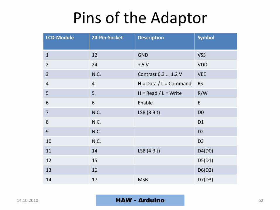
Pins of the Adaptor
14.10.2010 HAW - Arduino 52
LCD-Module 24-Pin-Socket Description Symbol
1 12 GND VSS
2 24 + 5 V VDD
3 N.C. Contrast 0,3 … 1,2 V VEE
4 4 H = Data / L = Command RS
5 5 H = Read / L = Write R/W
6 6 Enable E
7 N.C. LSB (8 Bit) D0
8 N.C. D1
9 N.C. D2
10 N.C. D3
11 14 LSB (4 Bit) D4(D0)
12 15 D5(D1)
13 16 D6(D2)
14 17 MSB D7(D3)
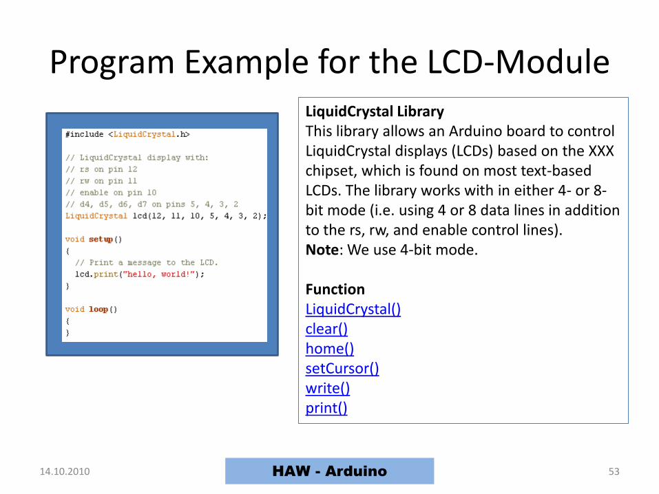
Program Example for the LCD-Module
14.10.2010 HAW - Arduino 53
LiquidCrystal LibraryThis library allows an Arduino board to control LiquidCrystal displays (LCDs) based on the XXX chipset, which is found on most text-based LCDs. The library works with in either 4- or 8-bit mode (i.e. using 4 or 8 data lines in addition to the rs, rw, and enable control lines). Note: We use 4-bit mode.
FunctionLiquidCrystal()clear()home()setCursor()write()print()

The Voltmeter
14.10.2010 HAW - Arduino 54
Protection CircuitGeneration of
the Input Voltage
Power Supply
Arduino and DisplayPre-Amplifier
Input Voltage

14.10.2010 HAW - Arduino 55

Characteristics of the Thermometer
• NTC:
• Input-range: 0 °C to 100 °C
• Buzzer alarm, if temperature encreases 90 °C
• Output on LCD :
14.10.2010 HAW - Arduino 56
4 2 C
1 0 8 ° F
°
Temperature / °C Resistor / kΩ
0 27,25
50 4,162
100 0,949

Tasks for the Thermometer
• Download the datasheet of the NTC-resistor
• Linearize the characteristic of the NTC in therange from 0 °C to 100 °C by connecting a serial resistor RL = R50 of the NTC.
• Develop the resulting characteristic
• Substitute the resulting characteristic by a straight line mT = f(Θ)
14.10.2010 57
LΘ
ΘL
RR
Rm
HAW - Arduino

14.10.2010 58HAW - Arduino

14.10.2010 HAW - Arduino 59
Arduino Board
VCC
GND
(from USB)
Pin 2
5 V
NTC
LCD-Module
RL
7

Tasks for Analog Input and PWM Output
• Dimm an LED with a potentiometer
• Check the function of the multicolour LED
• Write a program for controlling the colour of themulticolour LED with a potentiometer
• Control the rpm of the DC-motor with a potentiometer
• Sense the dark with the photoresistor
• Write a program for the piezo buzzer to play a melody
14.10.2010 60HAW - Arduino
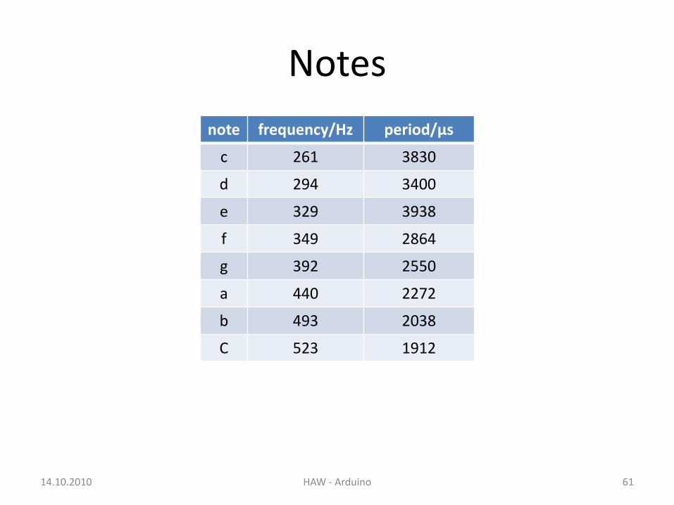
Notes
14.10.2010 HAW - Arduino 61
note frequency/Hz period/μs
c 261 3830
d 294 3400
e 329 3938
f 349 2864
g 392 2550
a 440 2272
b 493 2038
C 523 1912
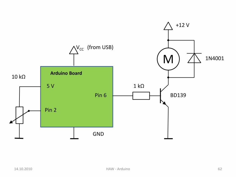
14.10.2010 HAW - Arduino 62
Pin 6
Arduino Board
VCC
GND
(from USB)
1 kΩ
M
+12 V
Pin 2
5 V
1N4001
BD139
10 kΩ

14.10.2010 HAW - Arduino 63
Arduino Board
VCC
GND
(from USB)
Pin 2
5 V
RL
220 Ω

Piezo Buzzer as Sensor
14.10.2010 HAW - Arduino 64
Tasks• Piezo-sensor: input value -> serial out • Piezo-sensor: input value -> buzzer frequency
Introduction• Piezo buzzers exhibit the reverse piezoelectric effect.• The normal piezoelectric effect is generating electricity
from squeezing a crystal.• Can get several thousand volts, makes a spark
Piezo Knock Sensor• To read a piezo you can connect it to an analog input, but: - You
need to drain off any voltage with a resistor• The protection diodes inside the AVR chip protect against the high
voltage

14.10.2010 HAW - Arduino 65
Arduino Board
VCC
GND
(from USB)
Pin 2
5 V
1 MΩ

Servo Motor
14.10.2010 HAW - Arduino 66
Servos are DC motors with built in gearing and feedback control loop circuitry.
Servo WiringAll servos have three wires:
Black or Brown is for ground. Red is for power (~4.8-6V). Yellow, Orange, or White is the signal wire (3-5V).
Tasks• Pot position 0…180° to servo position and LCD• Railroad crossing barrier• Railroad crossing sign (blinking, beep)

Library for the Servo Motor 1
14.10.2010 HAW - Arduino 67
Servo libraryThis library allows an Arduino board to control RC servo motors. Servos have integrated gears and a shaft that can precisely controlled. Standard servos allow the shaft to be positioned at various angles, usually between 0 and 180 degrees. Continuous rotation servos allow the rotation of the shaft to be set to various speeds.
As of Arduino 0017, the Servo library supports up to 12 motors on most Arduino boards and 48 on the Arduino Mega. On boards other than the Mega, use of the library disables analogWrite() (PWM) functionality on pins 9 and 10, whether or not there is a Servo on those pins. On the Mega, up to 12 servos can be used without interfering with PWM functionality; use of 12 to 23 motors will disable PWM on pins 11 and 12.
In Arduino 0016 and earlier, the Servo library uses functionality built in to the hardware, and works only on pins 9 and 10 (and does not work on the Arduino Mega). In this case, if only one servo is used, the other pin cannot be used for normal PWM output with analogWrite(). For example, in Arduino 0016 and earlier, you can't have a servo on pin 9 and PWM output on pin 10.

Library for the Servo Motor 2
14.10.2010 HAW - Arduino 68
CircuitServo motors have three wires: power, ground, and signal. The power wire is typically red, and should be connected to 5V power supply. The ground wire is typically black or brown and should be connected to a ground pin. The signal pin is typically yellow, orange or white and should be connected to a digital pin on the Arduino board. Note servos draw considerable power, so if you need to drive more than one or two, you need a separate power supply (not the +5V pin on your Arduino!).
Functionsattach()write()read()attached()detach()
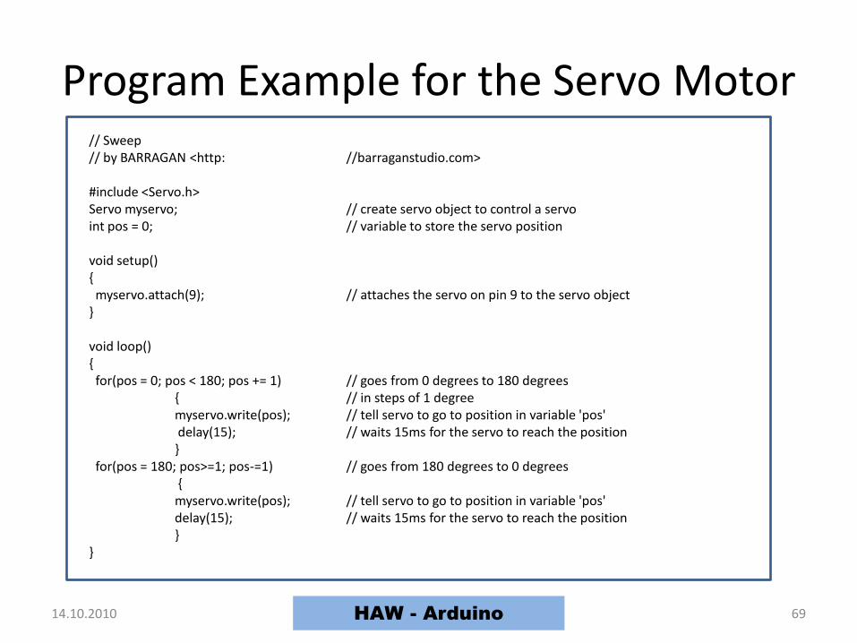
Program Example for the Servo Motor
14.10.2010 HAW - Arduino 69
// Sweep// by BARRAGAN <http: //barraganstudio.com>
#include <Servo.h> Servo myservo; // create servo object to control a servo int pos = 0; // variable to store the servo position
void setup() myservo.attach(9); // attaches the servo on pin 9 to the servo object
void loop() for(pos = 0; pos < 180; pos += 1) // goes from 0 degrees to 180 degrees
// in steps of 1 degree myservo.write(pos); // tell servo to go to position in variable 'pos' delay(15); // waits 15ms for the servo to reach the position
for(pos = 180; pos>=1; pos-=1) // goes from 180 degrees to 0 degrees myservo.write(pos); // tell servo to go to position in variable 'pos' delay(15); // waits 15ms for the servo to reach the position

14.10.2010 HAW - Arduino 70
Pin 6
Arduino Board
VCC
GND
(from USB)
M
+5 V
Pin 2
5 V
10 kΩServo
red
brown
orange

The Axis-Counter
Develop an axis-counter for the model train using:
• Infrared emitting LED TSHA 6203
• Photodiode SFH203P
• Comparator LM311
14.10.2010 71HAW - Arduino