Embed Size (px)
Citation preview
Flight & Operators Manual HFOMJ22-2-3/10 - 1 -
-Operator Manual Section 1 to 6
-Maintenance Manual Section 7
X-AIR HAWK
X-AIR HAWK JABIRU (with Jabiru 2200)
Wessex light Aeroplane Co. Ltd. 7 Fullands Ave, Taunton. Somerset. TA1 3DE UK
01823 256258 FAX 01823 256258 email [email protected]
Flight & Operators Manual HFOMJ22-2-3/10 - 2 -
G-_ _ _ _ Serial No. _ _ _ _
Approving Authority:
Popular Flying Association, Turweston Aerodrome, Brackley, Northants NN13 5YD, UK
by delegation from the United Kingdom Civil Aviation Authority
Manufacturer:
Raj Hamsa Ultralights Ltd., No 40, Goshala Road, Mahadevapura, Bangalore-560 048, India.
Importer:
Wessex Light Aeroplane Co. LTD., 7 Fullands Avenue, Taunton, Somerset TA1 3DE, UK
This manual is a legal document, approved for use with XAIR Hawk microlight aircraft issued with a
United Kingdom Homebuilt Permit to Fly.
It must remain with the aircraft, and may not be amended or altered without authority from either the
PFA or UK CAA.
All pilots should read this manual before flying as pilot in command of the aircraft to which it refers.
Approved for issue:
Francis Donaldson Paul Mulcahy Chief Technical Officer Project Test Pilot Popular Flying Association CAA
Flight & Operators Manual HFOMJ22-2-3/10 - 3 -
CONTENTS
INTRODUCTION (Pages 6 to 8) SECTION 1 : General Information (Pages 9 to 12) 1-1 Overall dimensions 1-2 Design Specifications
1-2.1 Dimensions 1-2.2 Landing gear 1-2.3 Control surface deflections 1-2.4 Fuel tank 1-2.5 Wings 1-2.6 Airframe 1-2.7 Seats 1-2.8 Controls
1-3 Rigging settings SECTION 2 : Limitations (Pages 13 to 15) 2-1 Certification type 2-2 Pilot competence 2-3 Conditions of use 2-4 Load factor 2-5 Weight and balance 2-6 Speeds limitations SECTION 3 : Powerplant (Page 16) 3-1 Jabiru 2200
3-1.1 Manufacturer 3-1.2 Technical data 3-1.3 Propeller 3-1.4 Noise pollution
SECTION 4 : Performance (Page 17) 4-1 X-AIR Hawk Jabiru
4-1.1 Service ceiling 4-1.2 Take off distance 4-1.3 Climb 4-1.4 Speeds 4-1.5 Engine off 4-1.6 Landing
Flight & Operators Manual HFOMJ22-2-3/10 - 4 -
SECTION 5 : Checks and Procedures (Pages 18 to 24) 5-1 Pre-flight inspection 5-1.1 Cockpit 5-1.2 Engine 5-1.3 Airframe 5-2 Engine start 5-2.1 Engine cold 5-2.2 Engine hot 5-3 Pre take-off checks 5-4 Take-off 5-5 Climb 5-6 Turns 5-7 Flight in turbulence 5-8 Stall 5-8.1 Engine off 5-8.2 Full throttle 5-9 Cruise 5-10 Descent, approach, landing 5-11 Crosswind 5-12 Engine stop 5-13 Parking 5-14 Performance SECTION 6 : Emergency procedures (Pages 25 to 27) 6-1 Engine failure, emergency landing 6-1.1 Before take-off
6-1.2 On take-off 6-1.3 In flight
6-2 Fire 6-2.1 Engine fire 6-2.2 Cabin fire
6-2.3 Electrical fire 6-3 Regulator failure 6-4 Landing without elevator 6-5 Emergency landing with engine 6-6 Emergency landing on water 6-7 Emergency landing on trees 6-8 Flight in heavy rain 6-9 Flight in icing conditions 6-10 Spin SECTION 7 : Maintenance (Pages 28 to 36) 7-1 Dismantling for transport 7-2 Airframe maintenance 7-3 Propeller 7-4 Powerplant maintenance 7-4.1 Jabiru 2200

Flight & Operators Manual HFOMJ22-2-3/10 5 /35
TABLE OF AMENDMENTS
Issue Date
Initial Issue July 2007
2nd Issue March 2010
Flight & Operators Manual HFOMJ22-2-3/10 6 /35
INTRODUCTION
The X-AIR Hawk is a two seat, three-axis microlight aircraft which has been certified in the
United Kingdom to the requirements of British Civil Airworthiness Requirements (BCAR) Section S issue 3 under the supervision and control of the Popular Flying Association.
This manual is not intended to teach you to build or fly the aircraft. A separate build manual is
supplied with each kit and learning to fly should be carried out under the supervision of a flying instructor experienced on microlights.
The information in this manual will enable a qualified pilot to fly the aircraft safely, although conversion training by an instructor familiar with the type is strongly advised. It also contains information on routine maintenance and minor repairs.
Note that options and accessories may be available from the manufacturer which are currently
not approved for use in the UK. Two separate logbooks should be maintained for your aircraft, one for the airframe and one
for the engine. As required by the authorities, all entries must be made in the logbook in ink and within 7 days of the event.
Any changes made to the aircraft's characteristics as recorded in its type certificate (engine,
propeller or any other part) must be recorded and approved by the PFA. It is also the pilots responsibility to check that all necessary documentation required by local
regulations is on board the aircraft before each flight. This aircraft can be flown by holders of the following licences:
* JAR PPL SEP, UK PPL (A) with SEP or Microlight ratings. * UK NPPL with microlight rating * NPPL SSEA with differences training for microlight aircraft. * Pilots with microlight rating for Flexwings should carry out difference training for 3 Axis aircraft. * Pilots with JAR or UK PPL(A) ratings are strongly advised to carry out difference training for microlight aircraft.
Never forget: You alone are responsible for the safe handling of your X-AIR Hawk.
Constant care and vigilance are essential. Happy flying!
Flight & Operators Manual HFOMJ22-2-3/10 7 /35
TO VALIDATE THE MANUFACTURERS WARRANTY:
THIS FORM MUST BE COMPLETED AND RETURNED TO
Wessex Light Aeroplane Co., 7 Fullands Avenue, Taunton, Somerset TA1 3DE, UK
WARNING
Even in the best of conditions, microlight flying may be hazardous. The user of this microlight acknowledges the existence of such hazards. Before his first flight, the user must read this manual and follow exactly the instructions given. He should be aware that the weight of any additional equipment or options fitted increases the empty weight of the aircraft and will decrease its useful load and performance accordingly, since maximum weight cannot be exceeded. The user must carry out all Mandatory Service Bulletins issued by the manufacturer. Any alterations or repair other than those specified by the manufacturer, or carried out without the manufacturer's agreement shall void the warranty. The user must hold a current and relevant pilot license. Raj Hamsa cannot be held responsible for any incidents or accidents caused by improper assembly, or reckless use of the aircraft, particularly when flying in bad weather, performing aerobatics maneuvers, or maneuvers exceeding the flight envelope. Signed.................................................................... Date ........................................................ Name and address : ........................................................................................................ .................................................................................................................................................................................................................................................................................................................. Aircraft registration: ................................................. Serial N°: ..............................................................… Engine type : ……………………………………… Engine N° : ………………………………………… Propeller type : ……………………………………. Propeller N° :……………………………………….. Options / accessories fitted : ……………………………………………………………………….
Flight & Operators Manual HFOMJ22-2-3/10 8 /35
Owner Record Sheet
Owner N°1 Name and address : ..........................................................................……….......…….................. ....................................................................................................................….....…..................... ............................................................................................................................…..................… Date Purchased..................................................... Date Sold...……............................................ Comments...........................................................................................................…...................... ............................................................................................................................…...................... Owner N°2 Name and address : ..........................................................................……….......…….................. ....................................................................................................................….....…..................... ............................................................................................................................…..................… Date Purchased..................................................... Date Sold...……............................................ Comments...........................................................................................................…...................... ............................................................................................................................…...................... Owner N°3 Name and address : ..........................................................................……….......…….................. ....................................................................................................................….....…..................... ............................................................................................................................…..................… Date Purchased..................................................... Date Sold...……............................................ Comments...........................................................................................................…...................... ............................................................................................................................…...................... Owner N°4 Name and address : ..........................................................................……….......…….................. ....................................................................................................................….....…..................... ............................................................................................................................…..................… Date Purchased..................................................... Date Sold...……............................................ Comments...........................................................................................................…...................... ............................................................................................................................…...................... Owner N°5 Name and address : ..........................................................................……….......…….................. ....................................................................................................................….....…..................... ............................................................................................................................…..................… Date Purchased..................................................... Date Sold...……............................................ Comments...........................................................................................................…...................... ............................................................................................................................…......................
Flight & Operators Manual HFOMJ22-2-3/10 9 /35
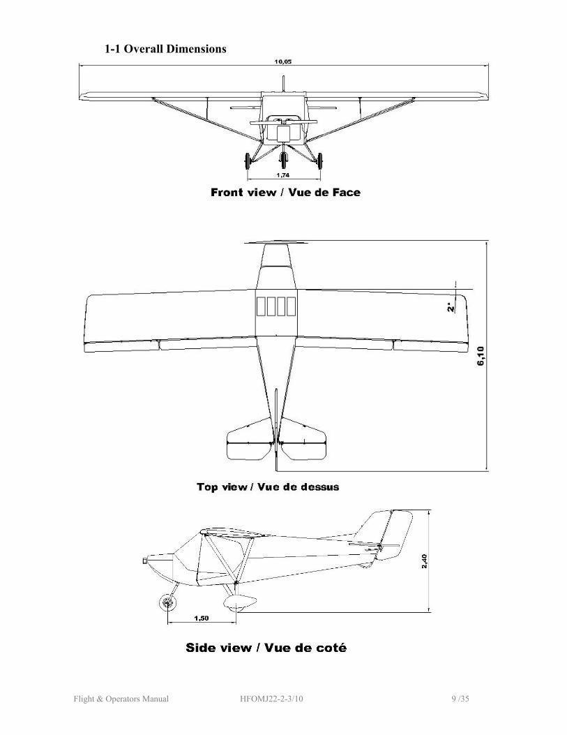
1-1 Overall Dimensions
Flight & Operators Manual HFOMJ22-2-3/10 10 /35
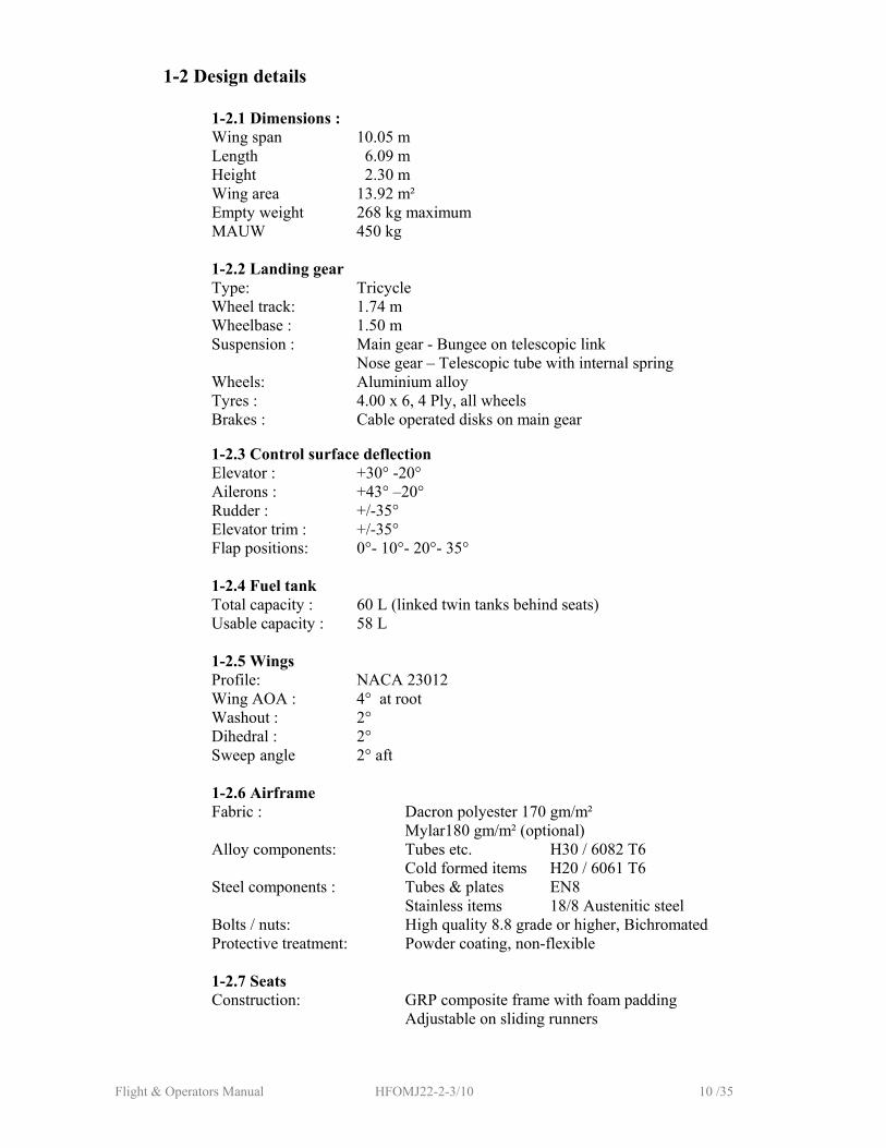
1-2 Design details
1-2.1 Dimensions : Wing span 10.05 m Length 6.09 m Height 2.30 m Wing area 13.92 m² Empty weight 268 kg maximum MAUW 450 kg
1-2.2 Landing gear Type: Tricycle Wheel track: 1.74 m Wheelbase : 1.50 m Suspension : Main gear - Bungee on telescopic link Nose gear – Telescopic tube with internal spring Wheels: Aluminium alloy Tyres : 4.00 x 6, 4 Ply, all wheels Brakes : Cable operated disks on main gear
1-2.3 Control surface deflection
Elevator : +30° -20° Ailerons : +43° –20°
Rudder : +/-35° Elevator trim : +/-35° Flap positions: 0°- 10°- 20°- 35°
1-2.4 Fuel tank Total capacity : 60 L (linked twin tanks behind seats) Usable capacity : 58 L
1-2.5 Wings Profile: NACA 23012 Wing AOA : 4° at root Washout : 2° Dihedral : 2° Sweep angle 2° aft
1-2.6 Airframe Fabric : Dacron polyester 170 gm/m² Mylar180 gm/m² (optional) Alloy components: Tubes etc. H30 / 6082 T6
Cold formed items H20 / 6061 T6 Steel components : Tubes & plates EN8
Stainless items 18/8 Austenitic steel Bolts / nuts: High quality 8.8 grade or higher, Bichromated Protective treatment: Powder coating, non-flexible
1-2.7 Seats
Construction: GRP composite frame with foam padding Adjustable on sliding runners

Flight & Operators Manual HFOMJ22-2-3/10 11 /35
1-2.8 Controls
Type : Full 3 axis Rudder : Pedals linked to rudder with cables
Nosewheel steering : Rudder pedals by solid links Control stick : Dual / between legs Throttle : Dual / left hand Elevator linkage : Push pull tube Aileron linkage : 3 mm cables + push-pull tubes Flaps linkage : Push-pull tubes Brakes : Toe operated, pilot side pedals only
Flight & Operators Manual HFOMJ22-2-3/10 12 /35
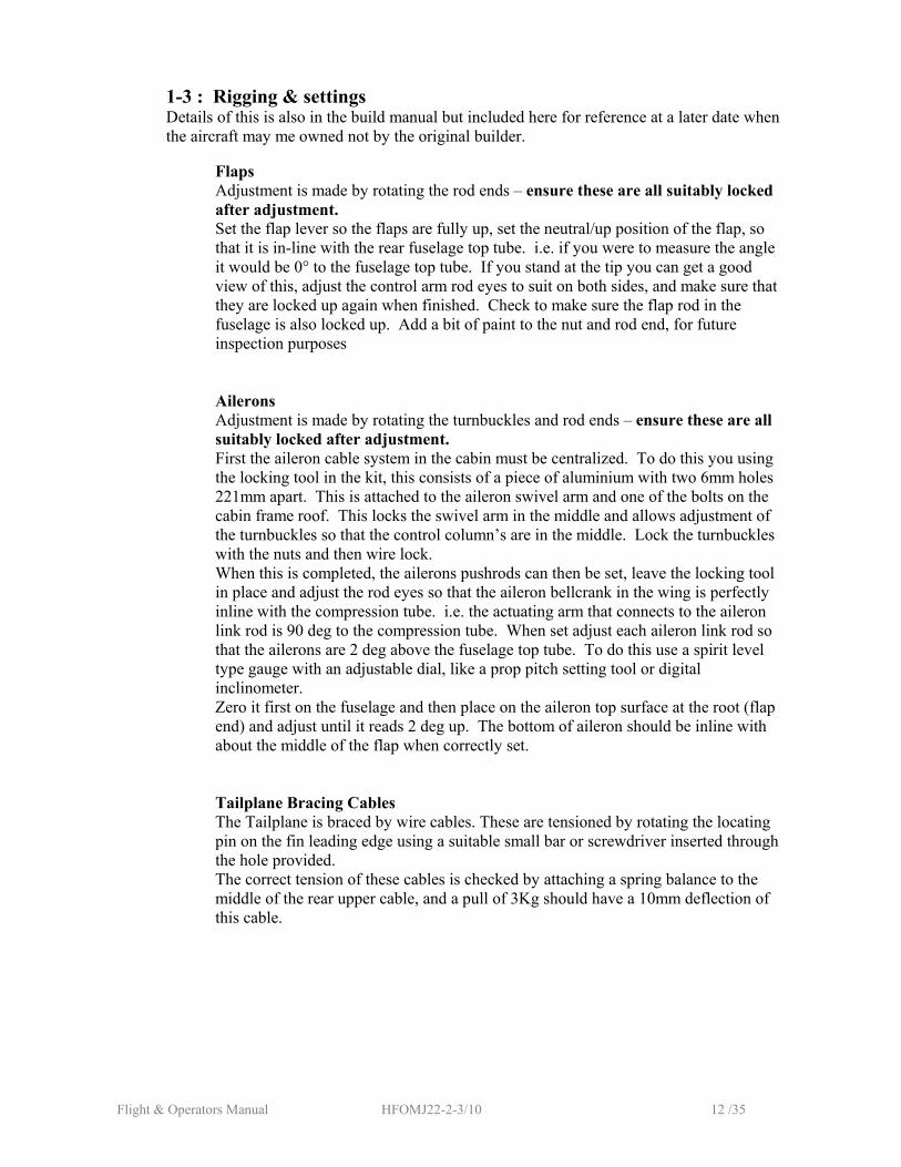
1-3 : Rigging & settings Details of this is also in the build manual but included here for reference at a later date when the aircraft may me owned not by the original builder.
Flaps Adjustment is made by rotating the rod ends – ensure these are all suitably locked after adjustment. Set the flap lever so the flaps are fully up, set the neutral/up position of the flap, so that it is in-line with the rear fuselage top tube. i.e. if you were to measure the angle it would be 0° to the fuselage top tube. If you stand at the tip you can get a good view of this, adjust the control arm rod eyes to suit on both sides, and make sure that they are locked up again when finished. Check to make sure the flap rod in the fuselage is also locked up. Add a bit of paint to the nut and rod end, for future inspection purposes
Ailerons Adjustment is made by rotating the turnbuckles and rod ends – ensure these are all suitably locked after adjustment. First the aileron cable system in the cabin must be centralized. To do this you using the locking tool in the kit, this consists of a piece of aluminium with two 6mm holes 221mm apart. This is attached to the aileron swivel arm and one of the bolts on the cabin frame roof. This locks the swivel arm in the middle and allows adjustment of the turnbuckles so that the control column’s are in the middle. Lock the turnbuckles with the nuts and then wire lock. When this is completed, the ailerons pushrods can then be set, leave the locking tool in place and adjust the rod eyes so that the aileron bellcrank in the wing is perfectly inline with the compression tube. i.e. the actuating arm that connects to the aileron link rod is 90 deg to the compression tube. When set adjust each aileron link rod so that the ailerons are 2 deg above the fuselage top tube. To do this use a spirit level type gauge with an adjustable dial, like a prop pitch setting tool or digital inclinometer. Zero it first on the fuselage and then place on the aileron top surface at the root (flap end) and adjust until it reads 2 deg up. The bottom of aileron should be inline with about the middle of the flap when correctly set. Tailplane Bracing Cables The Tailplane is braced by wire cables. These are tensioned by rotating the locating pin on the fin leading edge using a suitable small bar or screwdriver inserted through the hole provided. The correct tension of these cables is checked by attaching a spring balance to the middle of the rear upper cable, and a pull of 3Kg should have a 10mm deflection of this cable.
Flight & Operators Manual HFOMJ22-2-3/10 13 /35
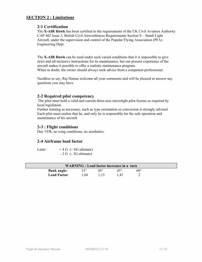
SECTION 2 : Limitations 2-1 Certification The X-AIR Hawk has been certified to the requirements of the UK Civil Aviation Authority CAP 482 Issue 3, British Civil Airworthiness Requirements Section S – Small Light Aircraft, under the supervision and control of the Popular Flying Association (PFA) Engineering Dept. The X-AIR Hawk can be used under such varied conditions that it is impossible to give strict and all-inclusive instructions for its maintenance, but our present experience of the aircraft makes it possible to offer a realistic maintenance program.
When in doubt, the owner should always seek advice from a competent professional.
Needless to say, Raj Hamsa welcome all your comments and will be pleased to answer any questions you may have.
2-2 Required pilot competency The pilot must hold a valid and current three-axis microlight pilot license as required by local legislation. Further training as necessary, such as type orientation or conversion is strongly advised. Each pilot must realize that he, and only he is responsible for the safe operation and maintenance of his aircraft.
2-3 : Flight conditions Day VFR, no icing conditions, no aerobatics.
2-4 Airframe load factor Limit : + 4 G (+ 6G ultimate) - 2 G (- 3G ultimate)
WARNING : Load factor increases in a turn Bank angle: 15° 30° 45° 60° Load Factor 1,04 1,15 1,41 2
Flight & Operators Manual HFOMJ22-2-3/10 14 /35
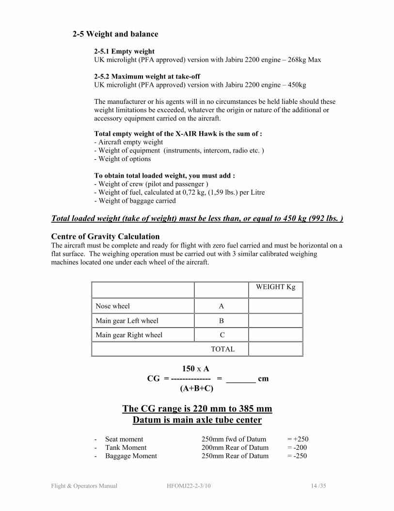
2-5 Weight and balance 2-5.1 Empty weight UK microlight (PFA approved) version with Jabiru 2200 engine – 268kg Max 2-5.2 Maximum weight at take-off UK microlight (PFA approved) version with Jabiru 2200 engine – 450kg
The manufacturer or his agents will in no circumstances be held liable should these weight limitations be exceeded, whatever the origin or nature of the additional or accessory equipment carried on the aircraft.
Total empty weight of the X-AIR Hawk is the sum of :
- Aircraft empty weight - Weight of equipment (instruments, intercom, radio etc. ) - Weight of options To obtain total loaded weight, you must add : - Weight of crew (pilot and passenger ) - Weight of fuel, calculated at 0,72 kg, (1,59 lbs.) per Litre
- Weight of baggage carried
Total loaded weight (take of weight) must be less than, or equal to 450 kg (992 lbs. )
Centre of Gravity Calculation The aircraft must be complete and ready for flight with zero fuel carried and must be horizontal on a flat surface. The weighing operation must be carried out with 3 similar calibrated weighing machines located one under each wheel of the aircraft.
WEIGHT Kg
Nose wheel A
Main gear Left wheel B
Main gear Right wheel C
TOTAL
150 x A
CG = -------------- = _______ cm (A+B+C)
The CG range is 220 mm to 385 mm Datum is main axle tube center
- Seat moment 250mm fwd of Datum = +250 - Tank Moment 200mm Rear of Datum = -200 - Baggage Moment 250mm Rear of Datum = -250
Flight & Operators Manual HFOMJ22-2-3/10 15 /35
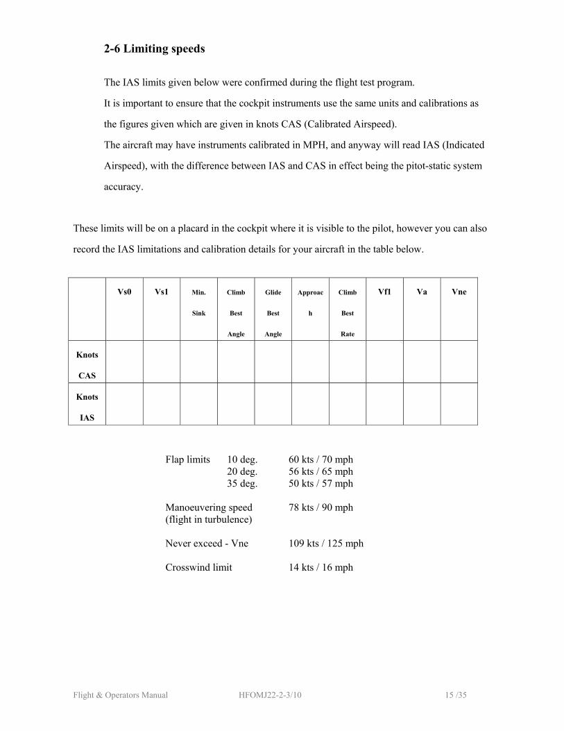
2-6 Limiting speeds The IAS limits given below were confirmed during the flight test program.
It is important to ensure that the cockpit instruments use the same units and calibrations as
the figures given which are given in knots CAS (Calibrated Airspeed).
The aircraft may have instruments calibrated in MPH, and anyway will read IAS (Indicated
Airspeed), with the difference between IAS and CAS in effect being the pitot-static system
accuracy.
These limits will be on a placard in the cockpit where it is visible to the pilot, however you can also
record the IAS limitations and calibration details for your aircraft in the table below.
Vs0 Vs1 Min.
Sink
Climb
Best
Angle
Glide
Best
Angle
Approac
h
Climb
Best
Rate
Vf1 Va Vne
Knots
CAS
Knots
IAS
Flap limits 10 deg. 60 kts / 70 mph 20 deg. 56 kts / 65 mph 35 deg. 50 kts / 57 mph Manoeuvering speed 78 kts / 90 mph (flight in turbulence) Never exceed - Vne 109 kts / 125 mph
Crosswind limit 14 kts / 16 mph

Flight & Operators Manual HFOMJ22-2-3/10 16 /35
SECTION 3 : Powerplant 3-1 Jabiru 2200
3-1.1 Manufacturer
Jabiru Aircraft Pty. Ltd. P.O. Box 5168 BUNDABERG WEST QLD 4670 AUSTRALIA
3-1.2 Technical data
Air cooled, 4 cylinder, 4 stroke Direct drive
Capacity : 2209cc Rated output : 80 hp (58KW) at 3300 rpm Max continuous rpm : 2900 Dual magneto ignition Installed weight : 63 kg
Service life : 1000 hours Fuel : Unleaded 95 octane minimum or AVGAS 100 LL Oil : follow engine manufacturer’s instructions
3-1.3 Propeller Newton two blade Diameter / Pitch: 61 x 42 Material : Wood with composite leading edge insert. 3-1.4 Noise certification
Conforms to 190M LSS.1 CAA Microlight Certificate no.2520
Flight & Operators Manual HFOMJ22-2-3/10 17 /35
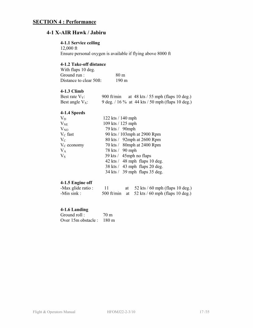
SECTION 4 : Performance
4-1 X-AIR Hawk / Jabiru
4-1.1 Service ceiling 12,000 ft Ensure personal oxygen is available if flying above 8000 ft
4-1.2 Take-off distance With flaps 10 deg.
Ground run : 80 m Distance to clear 50ft: 190 m
4-1.3 Climb Best rate VY: 900 ft/min at 48 kts / 55 mph (flaps 10 deg.) Best angle VX: 9 deg. / 16 % at 44 kts / 50 mph (flaps 10 deg.)
4-1.4 Speeds VD 122 kts / 140 mph VNE 109 kts / 125 mph VNO 79 kts / 90mph VC fast 90 kts / 103mph at 2900 Rpm VC 80 kts / 92mph at 2600 Rpm VC economy 70 kts / 80mph at 2400 Rpm VA 78 kts / 90 mph VS 39 kts / 45mph no flaps
42 kts / 48 mph flaps 10 deg. 38 kts / 43 mph flaps 20 deg. 34 kts / 39 mph flaps 35 deg.
4-1.5 Engine off -Max glide ratio : 11 at 52 kts / 60 mph (flaps 10 deg.) -Min sink : 500 ft/min at 52 kts / 60 mph (flaps 10 deg.)
4-1.6 Landing
Ground roll : 70 m Over 15m obstacle : 180 m
Flight & Operators Manual HFOMJ22-2-3/10 18 /35
SECTION 5 : Standard procedures 5-1 Pre-flight inspection This is where a safe flight begins. A full preflight inspection should be carried out before every take off.
5-1.1 Cockpit - master key off - ignition switches off - throttle closed
5-1.2 Engine
Stand facing the engine and check: - condition of propeller and propeller bolts and nuts - general engine condition, oil leaks etc. - engine mountings
- condition of ignition coils, spark plug leads and caps - condition of all fuel and oil lines - condition of cooling scoops and ducts - intake filter attachments - exhaust silencer mountings - exhaust system for apparent or incipient cracks - cowling and oil filler hatch fasteners all fully closed
5-1.3 Airframe Starting from the left, facing the aircraft, check: - undercarriage struts and bungee
- wheel bolts and the tyre pressures - wheel spat attachments
- front wing attachments - the upper and lower lift strut attachments - jury struts attachments - along the length of the lift struts
- condition of the wing leading edge - wing sail fabric
- attachment of compression tubes and drag cables inside the wing sail
Walk around to the trailing edge and check: - upper and lower rear lift strut attachments - compression tube and drag cables attachments - rear wing attachments - aileron fabric, hinges and aileron control linkages - flap fabric, hinges and flap controls linkages

Flight & Operators Manual HFOMJ22-2-3/10 19 /35
Walk back along the fuselage and check: - linkage on elevator bellcrank - fastenings and tension of tailplane bracing cables - clevises on push tubes to elevator bellcranks - elevator attach fittings - elevator and rudder hinges - condition of fabric on tail surfaces - shackles on rudder cables - fastenings of rear fuselage cover
Walk over to the right side and check: - shackles on rudder cables - condition of fabric on tail surfaces - elevator and rudder hinges - elevator attach fittings - clevises on push tubes to elevator bellcranks - fastenings and tension of tailplane bracing cables
- linkage on elevator bellcrank - fastenings of rear fuselage cover
Move forward and check:
- rudder cables are crossed - undercarriage struts and bungee - wheel bolts and the tyre pressures - wheel spat attachments Move along trailing edge and check: - rear wing attachments
- upper and lower rear strut attachments - compression tube and drag cables attachments - aileron fabric, hinges and aileron control linkages - flap fabric, hinges and flap controls linkages
- check safe and firm attachment of wing tip fairing (if fitted)
Move to the cabin along leading edge: - attachment of compression tubes and drag cables inside the wing sail - wing sail fabric - condition of the wing leading edge - along the length of the wing struts - jury struts attachments - the upper and lower wing strut attachments - front wing attachments
In the cockpit, check: - seat attachment, adjustment slide locked - harness attachment and condition
- condition and tension of control cables and linkages - fittings and condition of all cabin tubes - throttle cable at throttle lever and normal operation of throttle
- choke, fuel filter, fuel line, and electric pump - tank vents open and tank attachments - fuel quantity checked, fuel filler cap correctly closed - full and free movement of all controls
Flight & Operators Manual HFOMJ22-2-3/10 20 /35
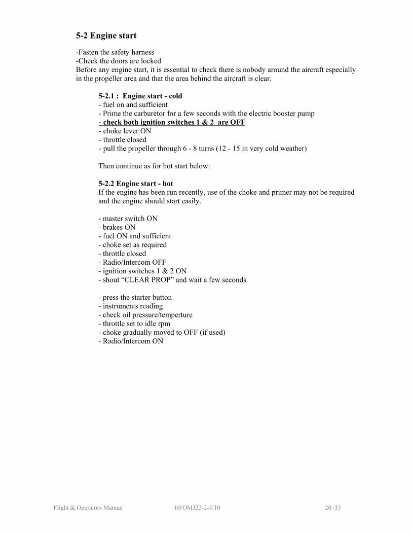
5-2 Engine start
-Fasten the safety harness -Check the doors are locked Before any engine start, it is essential to check there is nobody around the aircraft especially in the propeller area and that the area behind the aircraft is clear.
5-2.1 : Engine start - cold
- fuel on and sufficient - Prime the carburetor for a few seconds with the electric booster pump - check both ignition switches 1 & 2 are OFF - choke lever ON - throttle closed - pull the propeller through 6 - 8 turns (12 - 15 in very cold weather)
Then continue as for hot start below:
5-2.2 Engine start - hot
If the engine has been run recently, use of the choke and primer may not be required and the engine should start easily. - master switch ON - brakes ON - fuel ON and sufficient - choke set as required - throttle closed - Radio/Intercom OFF - ignition switches 1 & 2 ON - shout “CLEAR PROP” and wait a few seconds
- press the starter button - instruments reading - check oil pressure/temperture - throttle set to idle rpm - choke gradually moved to OFF (if used) - Radio/Intercom ON
Flight & Operators Manual HFOMJ22-2-3/10 21 /35
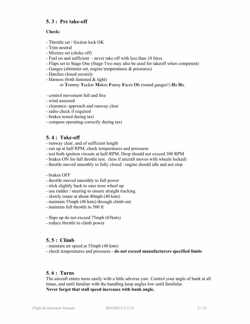
5. 3 : Pre take-off
Check: - Throttle set / friction lock OK - Trim neutral - Mixture set (choke off) - Fuel on and sufficient - never take off with less than 10 litres - Flaps set to Stage One (Stage Two may also be used for takeoff when competent) - Gauges (altimeter set, engine temperatures & pressures) - Hatches closed securely - Harness (both fastened & tight)
or Tommy Tucker Makes Funny Faces Oh (round gauges!) Ha Ha.
- control movement full and free - wind assessed - clearance: approach and runway clear - radio check if required - brakes tested during taxi - compass operating correctly during taxi
5. 4 : Take-off - runway clear, and of sufficient length - run up at half RPM, check temperatures and pressures - test both ignition circuits at half-RPM. Drop should not exceed 300 RPM - brakes ON for full throttle test. (less if aircraft moves with wheels locked)
- throttle moved smoothly to fully closed : engine should idle and not stop - brakes OFF
- throttle moved smoothly to full power - stick slightly back to ease nose wheel up - use rudder / steering to ensure straight tracking - slowly rotate at about 40mph (40 knts) - maintain 55mph (48 knts) through climb-out
- maintain full throttle to 500 ft - flaps up do not exceed 75mph (65knts) - reduce throttle to climb power
5. 5 : Climb - maintain air speed at 55mph (48 knts) - check temperatures and pressures - do not exceed manufacturers specified limits 5. 6 : Turns
The aircraft enters turns easily with a little adverse yaw. Control your angle of bank at all times, and until familiar with the handling keep angles low until familular. Never forget that stall speed increases with bank angle.
Flight & Operators Manual HFOMJ22-2-3/10 22 /35
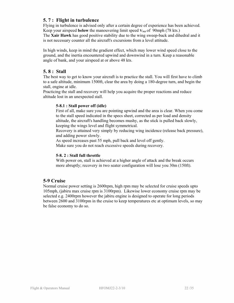
5. 7 : Flight in turbulence Flying in turbulence is advised only after a certain degree of experience has been achieved. Keep your airspeed below the manouvering limit speed VNO of 90mph (78 kts.) The Xair Hawk has good positive stability due to the wing sweep-back and dihedral and it is not necessary counter all the aircraft's excursions from a level attitude. In high winds, keep in mind the gradient effect, which may lower wind speed close to the ground, and the inertia encountered upwind and downwind in a turn. Keep a reasonable angle of bank, and your airspeed at or above 48 kts.
5. 8 : Stall
The best way to get to know your aircraft is to practice the stall. You will first have to climb to a safe altitude, minimum 1500ft, clear the area by doing a 180-degree turn, and begin the stall, engine at idle. Practicing the stall and recovery will help you acquire the proper reactions and reduce altitude lost in an unexpected stall.
5-8.1 : Stall power off (idle)
First of all, make sure you are pointing upwind and the area is clear. When you come to the stall speed indicated in the specs sheet, corrected as per load and density altitude, the aircraft's handling becomes mushy, as the stick is pulled back slowly, keeping the wings level and flight symmetrical. Recovery is attained very simply by reducing wing incidence (release back pressure), and adding power slowly. As speed increases past 55 mph, pull back and level off gently. Make sure you do not reach excessive speeds during recovery.
5-8. 2 : Stall full throttle
With power on, stall is achieved at a higher angle of attack and the break occurs more abruptly; recovery in two seater configuration will lose you 30m (150ft).
5-9 Cruise
Normal cruise power setting is 2600rpm, high rpm may be selected for cruise speeds upto 105mph, (jabiru max cruise rpm is 3100rpm). Likewise lower economy cruise rpm may be selected e.g. 2400rpm however the jabiru engine is designed to operate for long periods between 2600 and 3100rpm in the cruise to keep temperatures etc at optimum levels, so may be false economy to do so.
Flight & Operators Manual HFOMJ22-2-3/10 23 /35
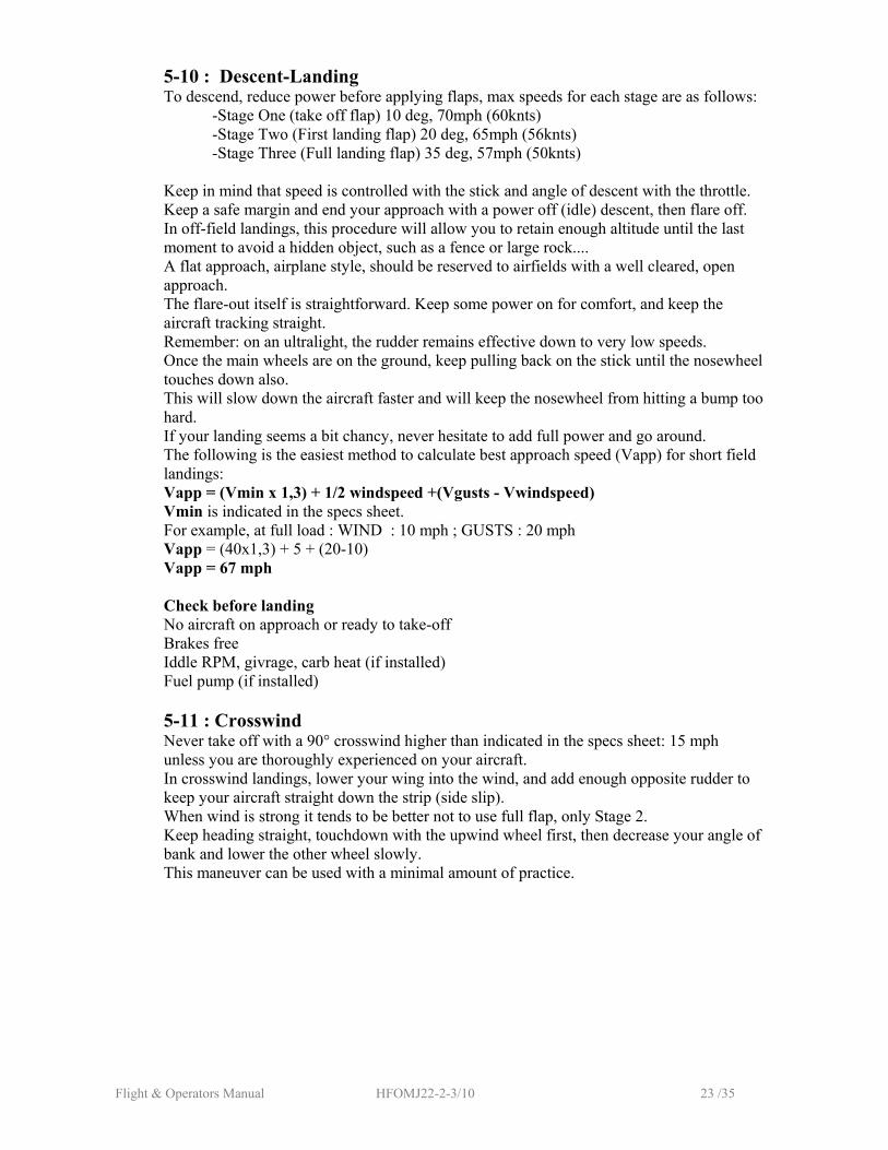
5-10 : Descent-Landing To descend, reduce power before applying flaps, max speeds for each stage are as follows: -Stage One (take off flap) 10 deg, 70mph (60knts) -Stage Two (First landing flap) 20 deg, 65mph (56knts) -Stage Three (Full landing flap) 35 deg, 57mph (50knts) Keep in mind that speed is controlled with the stick and angle of descent with the throttle. Keep a safe margin and end your approach with a power off (idle) descent, then flare off. In off-field landings, this procedure will allow you to retain enough altitude until the last moment to avoid a hidden object, such as a fence or large rock.... A flat approach, airplane style, should be reserved to airfields with a well cleared, open approach. The flare-out itself is straightforward. Keep some power on for comfort, and keep the aircraft tracking straight. Remember: on an ultralight, the rudder remains effective down to very low speeds. Once the main wheels are on the ground, keep pulling back on the stick until the nosewheel touches down also. This will slow down the aircraft faster and will keep the nosewheel from hitting a bump too hard. If your landing seems a bit chancy, never hesitate to add full power and go around. The following is the easiest method to calculate best approach speed (Vapp) for short field landings: Vapp = (Vmin x 1,3) + 1/2 windspeed +(Vgusts - Vwindspeed) Vmin is indicated in the specs sheet. For example, at full load : WIND : 10 mph ; GUSTS : 20 mph Vapp = (40x1,3) + 5 + (20-10) Vapp = 67 mph Check before landing No aircraft on approach or ready to take-off Brakes free Iddle RPM, givrage, carb heat (if installed) Fuel pump (if installed)
5-11 : Crosswind
Never take off with a 90° crosswind higher than indicated in the specs sheet: 15 mph unless you are thoroughly experienced on your aircraft. In crosswind landings, lower your wing into the wind, and add enough opposite rudder to keep your aircraft straight down the strip (side slip). When wind is strong it tends to be better not to use full flap, only Stage 2. Keep heading straight, touchdown with the upwind wheel first, then decrease your angle of bank and lower the other wheel slowly. This maneuver can be used with a minimal amount of practice.
Flight & Operators Manual HFOMJ22-2-3/10 24 /35
IMPORTANT NOTICE: Always keep in mind that any aircraft may experience unexpected engine failure. Hence, make sure you always have enough altitude to be able to pick as safe an emergency field as possible. Never overfly built up or hostile areas such as forests, swamps, etc.without an added margin of altitude to be able to reach safer terrain in case of engine failure. The same applies to your choice of maneuvering speed, especially in phases of flight which allow no room for improvisation (take off, climb out, landing). Give yourself an ample safety margin; you will never regret it.
5-12 : Stopping the engine On the ground:
Let the engine cool down for 30 seconds at half RPM before turning off the ignition. - parking brake on - radio and intercom: off - all switches: off - never close the fuel shut off (if fitted).
5- 13 : Parking and storage
(It is preferable to keep the X-AIR Hawk parked inside a hangar) If the X-AIR Hawk has to be left outside unattended:
- point the aircraft into the wind, and chock wheels - attach the stick with both safety harnesses - immobilize the rudder with a control lock or other - tie down the wings from the top of the struts to a "corkscrew "anchor in the ground - similarly, tie down the propeller shaft - in Summer, shade the instrument panel with an aluminum/Mylar film.
5-14 : Performances (m = 450 kg) The performance figures found in the following annexes represent averaged measured values. However, take into consideration that performance will vary with the power plant fitted on each aircraft. Performances at take off are greatly influenced by air density. Higher altitude and/or temperature will affect results. To clear 15m (approx.50ft) after take off, it is best to reach 50-55 mph before you come back on the stick. This will mean a longer roll, but will eventually result in a shorter distance to clear 15m (50 ft). Fuel consumption may vary with the mixture setting. Range will be estimated from the amount of fuel in the tank, the wind and a minimum safety reserve of 30minutes. Best gliding speed is lower if weight is lower. If the actual weight is 30% below maximum, the best gliding speed will be 15% lower than normally specified. Landing distance (to clear 15m) can be considerably shortened by side slipping, with stick into the wind and opposite rudder. Practice with a qualified instructor is mandatory.
Flight & Operators Manual HFOMJ22-2-3/10 25 /35
SECTION 6 : Emergency procedures
6-1 Engine failure - Emergency landing 6-1.1 : Before take-off, when taxiing
- throttle down - brake - cut off engine ignition
6-1.2 : During take-off
-set airspeed at 60 mph - land straight ahead; only minor course changes should be made, to avoid obstacles. - do not attempt to fly back to the runway: more often than not, you do not have enough height above ground to do so safely.
6-1.3:In flight Note: the ultralight flight being operate always considering this possibility, you must be close to a possible landing ground.
- check to see if the engine did not stop because of inadvertent action on: - engine ignition switch - throttle - fuel shut off
- Try the booster electric fuel pump (if fitted) - airspeed: 60 mph - look for a suitable landing field
- seatbelts tight, helmets secured - if you have enough altitude, flying down wind will allow to cover a greater distance, increasing your chances of finding a suitable field. - If the field is flat, land into the wind - if the ground is reasonably level, putting stick forward all the way will shorten your run
- if braking distance is restricted, full rudder into the wind Note: In a 10 mph wind, the energy to be absorbed by the brakes will be 2,5 higher landing downwind than upwind. - brake hard
6-2 Fire 6-2.1 : Engine fire
- close the fuel shut off (if fitted) - stop the electric pump if it is on (if fitted) - open full throttle - cabin heating: off (if fitted) - if possible, ask for help on the ground (fire brigade) - land as soon as possible
Flight & Operators Manual HFOMJ22-2-3/10 26 /35
6-2.2 : Fire in cockpit - close heating and ventilation - cut off auxiliary electric supply - if necessary, cut off engine ignition and shut off the fuel line - land as soon as possible
6-2.3 : Electric fire - close heating and ventilation
- cut off auxiliary electric supply - if necessary, cut off engine ignition and shut off the fuel line
- land as soon as possible
6-3 : Regulator failure Failure of the battery regulator may cause overheating of the battery and gas release.
- pull out the charge fuse - open the doors
- land as soon as possible
6-4 : Landing with elevator inoperative - control the aircraft with the trim tab - move the throttle very slowly while trimming with the tab - pick a fairly long landing field
- set airspeed at 50mph and 300ft/min for final approach (depending on wind and turbulence, a higher airspeed may be needed) - flare with the trim tab, keeping off the ground as long as possible, without throttling back
- immediately on touchdown, cut power
6-5 : Emergency landing with engine (due to weather conditions or imminent lack of fuel) - look for an appropriate landing site: check for possible obstacles (trees; power lines, fences); observe the slope of the field - make a full 360° turn over the field; the amount and direction of drift during the turn will indicate the speed and direction of the wind.
- overfly down low, into the wind, to make a thorough inspection of the field - seatbelts tight, helmets secured - make a normal landing - immediately on touch down, cut engine ignition - brake hard
6-6 : Emergency landing on water CAUTION : it is difficult to estimate height above water!! Get your passenger and yourself psychologically prepared for landing on water, and try to pick a landing course that will make swimming ashore easiest. Unlock the doors. Be prepared to unfasten your safety harness. (Same for your passenger) Touch down nose-up, as slowly and gently as possible. Once in the water, stay calm; leave the aircraft without taking anything with you.
Flight & Operators Manual HFOMJ22-2-3/10 27 /35
6-7 : Emergency landing on trees Prefer one or several low, bushy trees. Belts and helmets tight. Keep some speed on in final, as the air is often turbulent next to the trees. Pull up sharply to break your speed as soon as you hear contact with the branches. Good luck! 6-8 : Flight in hard rain
If the windshield fogs up, wipe with a soft cotton rag. Throttle down to limit wear on the propeller. Try to fly away from the rain.
6-9 : Flight in icing conditions
Although flying in icing conditions is prohibited; you may be caught in such conditions. Proceed as follows:
- carburetors heat: "ON" (if fitted) -turn around or change altitude for a less critical air temperature - increase power to reduce icing to minimum - plan on landing on the nearest airfield; if ice is building up fast, land off-field - ice on the leading edge increases your stall speed
- approach speed depending on thickness of ice: 50 to 55 mph; fly a shallow, "airplane" type descent, with engine at high revs.
6-10 : Unvolontary spin Use the following procedure to recover from an involuntary spin: - Close throttle.
- Centralise all controls. - Gently pull out of the ensuing dive.
IMPORTANT NOTE At very low speed, control the aircraft with rudder only.
Flight & Operators Manual HFOMJ22-2-3/10 28 /35
SECTION 7 : Maintenance
7-1 Wing removal for transport Preparing the aircraft for transport on a trailer or for off airport storage is a simple operation that can be carried out by two people in about 1/2 an hour. To avoid loosing any parts removed, replace any bolts, nuts, pins and rings back into the parts immediately after removal. If a pitot-static head is fitted on the wing strut, provision should be made to disconnect the pipes at some convenient point. It is then recommended to proceed as follows: -Disconnect ailerons control tubes in the cockpit. -Disconnect flaps control tubes from their horns. -Disconnect the wing fold safety cables. -One person supports the wing at its tip. Remove ring and pull out lower wing strut pin using supplied tool. Remove ring and pull out the front spar pin using the supplied tool. Remove ring and pullout the rear spar pin using the supplied tool. Slide the wing out and lift clear of the fuselage, lay on a soft smooth surface. The Main struts & jury struts can then be removed depending on method of storage or transport -Proceed the same way for the second wing. It may also be necessary remove the tailplanes to reduce the width if the aircraft is to be towed on a trailer. -Disconnect the elevator fork from the control horns on the elevator assembly. -Disconnect the trim cables from the trim tab -Remove the rings that secure the lower bracing cables under the fuselage. -Screw the bolt on the fin leading edge INWARDS by using a screwdriver or similar placed through the hole provided which will slacken the upper cables enough to remove them. -Pull the two stabilisers from the tapered mountings.
If the aircraft is to transported by trailer, it is very important to use foam or padding to protect all the parts and avoid damage. Items such as the rudder should be secured to prevent movement. Make a final check on the security of the load before setting off. To assemble proceed in the reverse order using new Nyloc new nuts, ensure cables are correctly routed and seated in their pulleys. A thorough pre-flight inspection is essential before flying.
Flight & Operators Manual HFOMJ22-2-3/10 29 /35
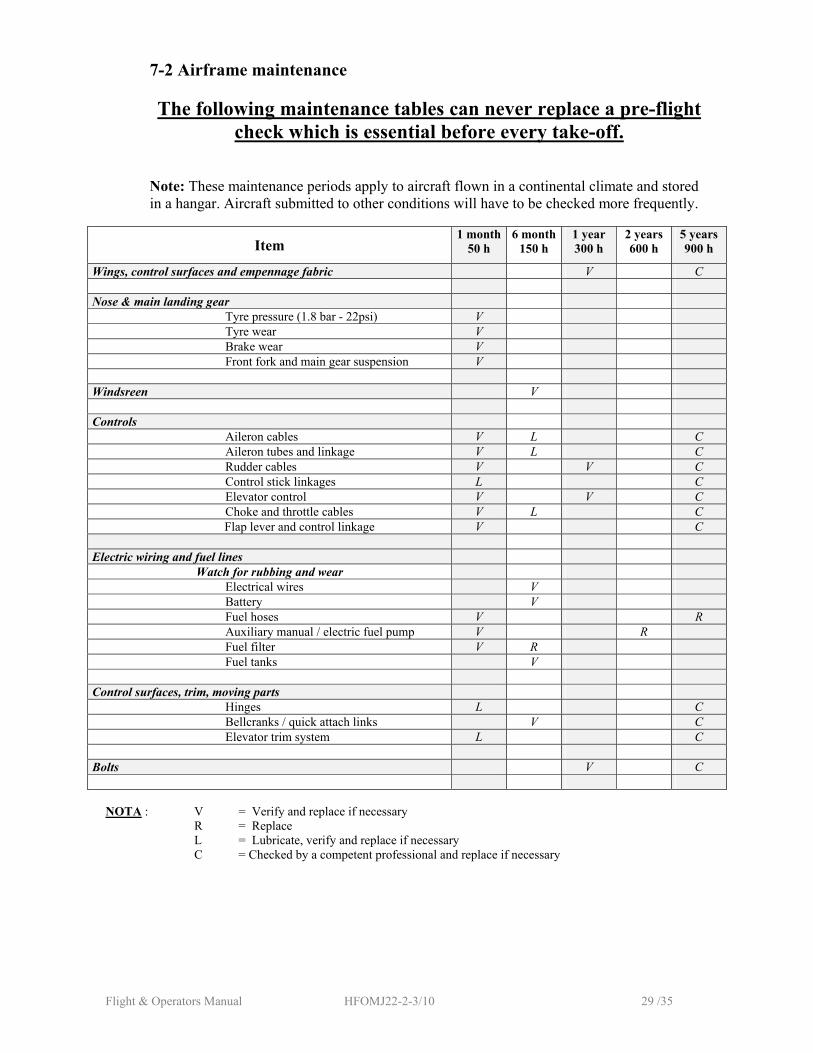
7-2 Airframe maintenance The following maintenance tables can never replace a pre-flight
check which is essential before every take-off. Note: These maintenance periods apply to aircraft flown in a continental climate and stored in a hangar. Aircraft submitted to other conditions will have to be checked more frequently.
Item 1 month
50 h 6 month
150 h 1 year 300 h
2 years 600 h
5 years 900 h
Wings, control surfaces and empennage fabric V C Nose & main landing gear
Tyre pressure (1.8 bar - 22psi) V Tyre wear V Brake wear V Front fork and main gear suspension V
Windsreen V Controls
Aileron cables V L C Aileron tubes and linkage V L C Rudder cables V V C Control stick linkages L C Elevator control V V C Choke and throttle cables V L C
Flap lever and control linkage V C Electric wiring and fuel lines
Watch for rubbing and wear Electrical wires V Battery V Fuel hoses V R Auxiliary manual / electric fuel pump V R Fuel filter V R Fuel tanks V
Control surfaces, trim, moving parts
Hinges L C Bellcranks / quick attach links V C Elevator trim system L C
Bolts V C
NOTA : V = Verify and replace if necessary R = Replace L = Lubricate, verify and replace if necessary C = Checked by a competent professional and replace if necessary
Flight & Operators Manual HFOMJ22-2-3/10 30 /35
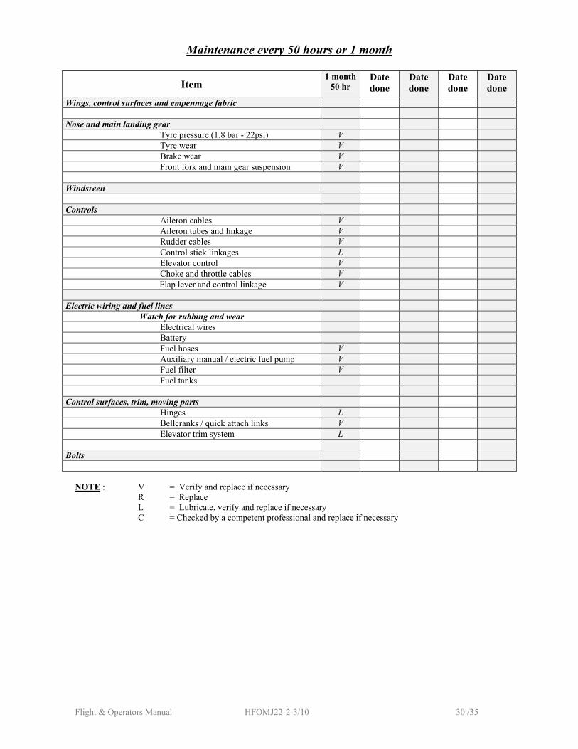
Maintenance every 50 hours or 1 month
Item 1 month
50 hr Date done
Date done
Date done
Date done
Wings, control surfaces and empennage fabric Nose and main landing gear
Tyre pressure (1.8 bar - 22psi) V Tyre wear V Brake wear V Front fork and main gear suspension V
Windsreen Controls
Aileron cables V Aileron tubes and linkage V Rudder cables V Control stick linkages L Elevator control V Choke and throttle cables V
Flap lever and control linkage V Electric wiring and fuel lines
Watch for rubbing and wear Electrical wires Battery Fuel hoses V Auxiliary manual / electric fuel pump V Fuel filter V Fuel tanks
Control surfaces, trim, moving parts
Hinges L Bellcranks / quick attach links V Elevator trim system L
Bolts
NOTE : V = Verify and replace if necessary R = Replace L = Lubricate, verify and replace if necessary C = Checked by a competent professional and replace if necessary
Flight & Operators Manual HFOMJ22-2-3/10 31 /35
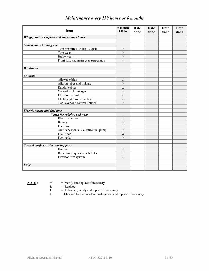
Maintenance every 150 hours or 6 months
Item 6 month150 hr
Date done
Date done
Date done
Date done
Wings, control surfaces and empennage fabric Nose & main landing gear
Tyre pressure (1.8 bar - 22psi) V Tyre wear V Brake wear V Front fork and main gear suspension V
Windsreen Controls
Aileron cables L Aileron tubes and linkage V Rudder cables L Control stick linkages V Elevator control L Choke and throttle cables L
Flap lever and control linkage V Electric wiring and fuel lines
Watch for rubbing and wear Electrical wires V Battery V Fuel hoses V Auxiliary manual / electric fuel pump V Fuel filter R Fuel tanks V
Control surfaces, trim, moving parts
Hinges L Bellcranks / quick attach links V Elevator trim system L
Bolts
NOTE : V = Verify and replace if necessary R = Replace L = Lubricate, verify and replace if necessary C = Checked by a competent professional and replace if necessary
Flight & Operators Manual HFOMJ22-2-3/10 32 /35
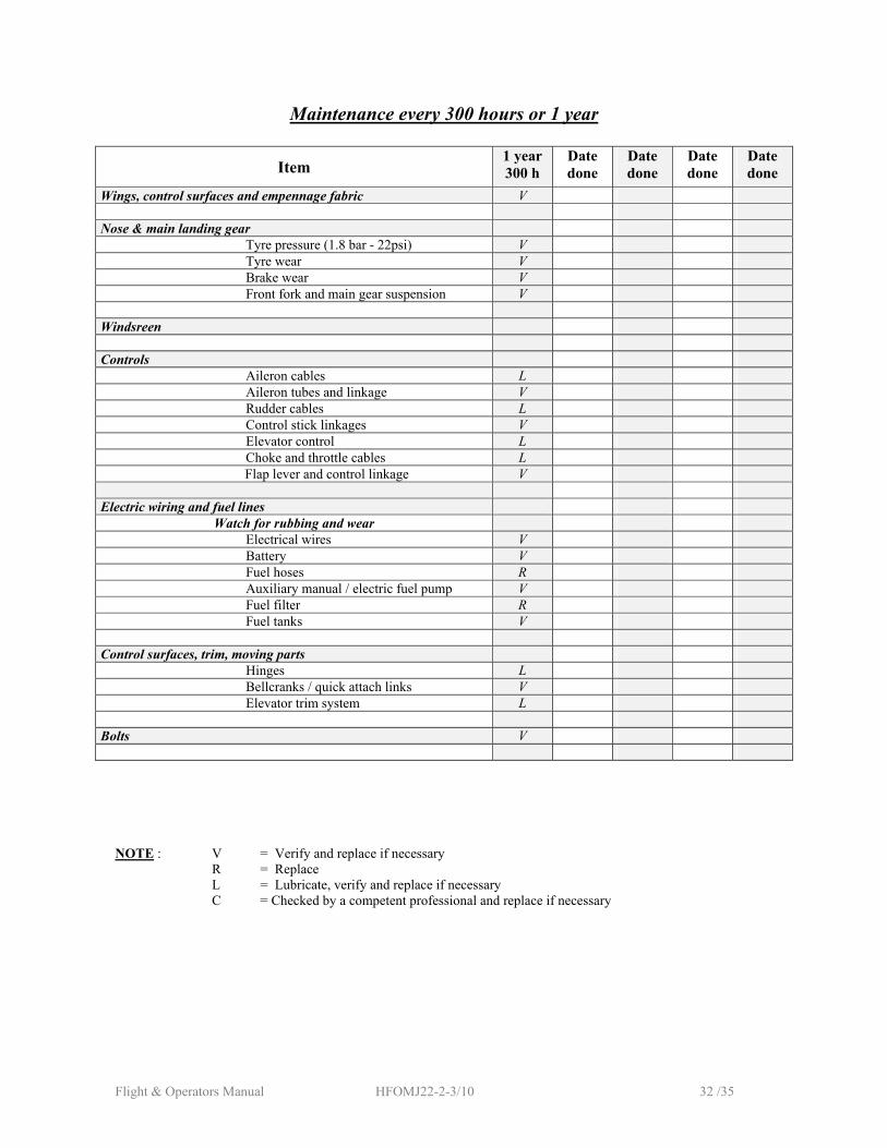
Maintenance every 300 hours or 1 year
Item 1 year 300 h
Date done
Date done
Date done
Date done
Wings, control surfaces and empennage fabric V Nose & main landing gear
Tyre pressure (1.8 bar - 22psi) V Tyre wear V Brake wear V Front fork and main gear suspension V
Windsreen Controls
Aileron cables L Aileron tubes and linkage V Rudder cables L Control stick linkages V Elevator control L Choke and throttle cables L
Flap lever and control linkage V Electric wiring and fuel lines
Watch for rubbing and wear Electrical wires V Battery V Fuel hoses R Auxiliary manual / electric fuel pump V Fuel filter R Fuel tanks V
Control surfaces, trim, moving parts
Hinges L Bellcranks / quick attach links V Elevator trim system L
Bolts V
NOTE : V = Verify and replace if necessary R = Replace L = Lubricate, verify and replace if necessary C = Checked by a competent professional and replace if necessary
Flight & Operators Manual HFOMJ22-2-3/10 33 /35
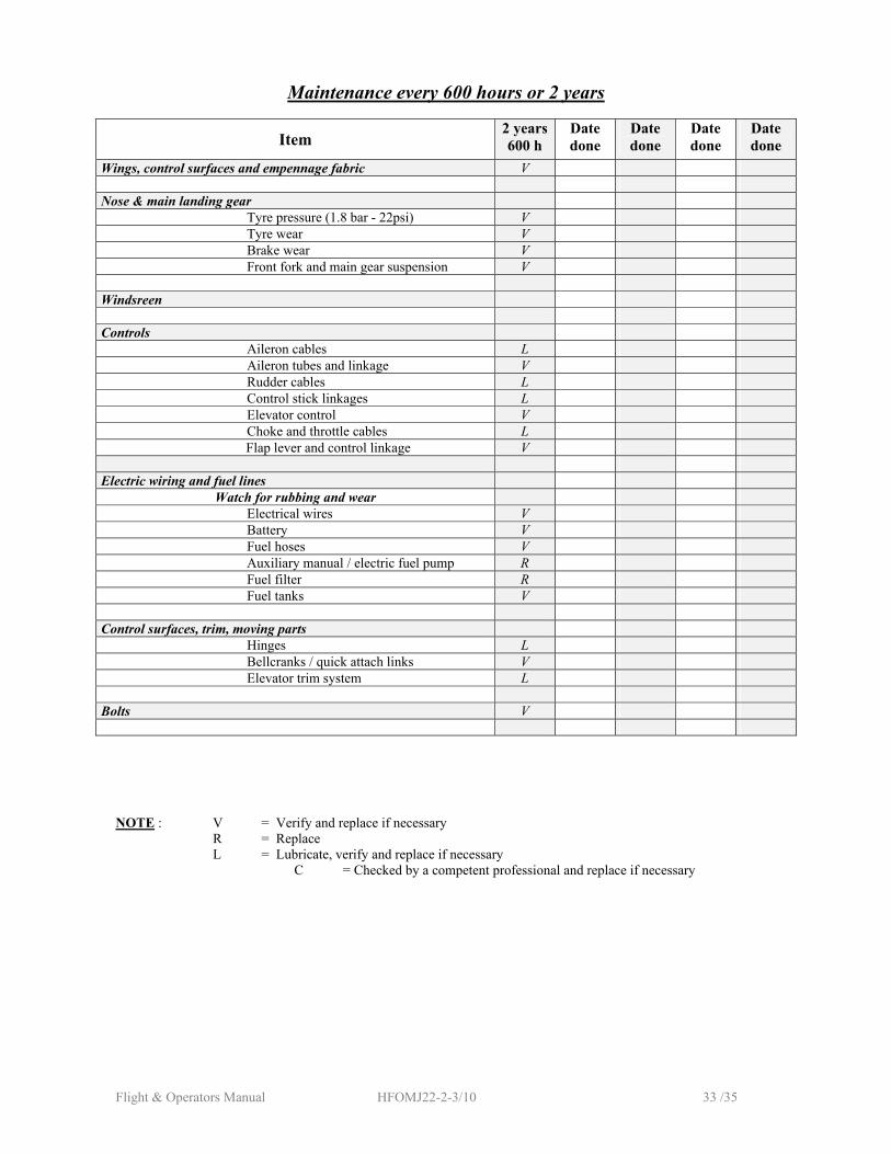
Maintenance every 600 hours or 2 years
Item 2 years600 h
Date done
Date done
Date done
Date done
Wings, control surfaces and empennage fabric V Nose & main landing gear
Tyre pressure (1.8 bar - 22psi) V Tyre wear V Brake wear V Front fork and main gear suspension V
Windsreen Controls
Aileron cables L Aileron tubes and linkage V Rudder cables L Control stick linkages L Elevator control V Choke and throttle cables L
Flap lever and control linkage V Electric wiring and fuel lines
Watch for rubbing and wear Electrical wires V Battery V Fuel hoses V Auxiliary manual / electric fuel pump R Fuel filter R Fuel tanks V
Control surfaces, trim, moving parts
Hinges L Bellcranks / quick attach links V Elevator trim system L
Bolts V
NOTE : V = Verify and replace if necessary R = Replace L = Lubricate, verify and replace if necessary
C = Checked by a competent professional and replace if necessary
Flight & Operators Manual HFOMJ22-2-3/10 34 /35
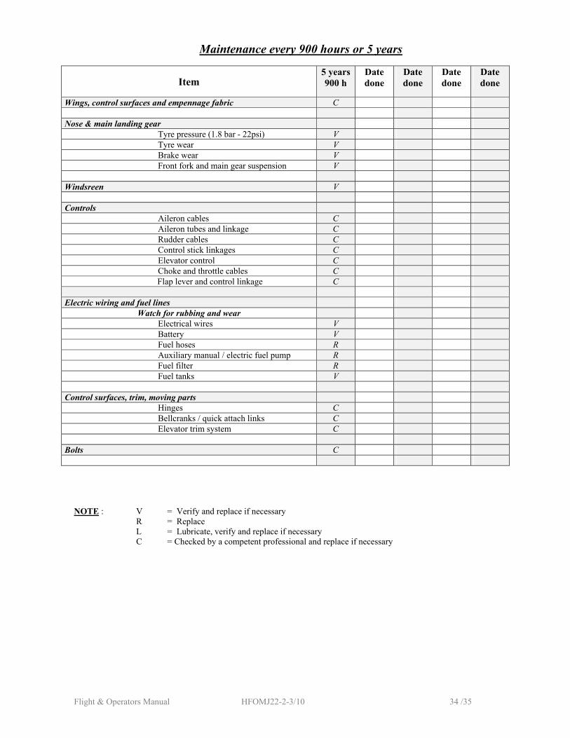
Maintenance every 900 hours or 5 years
Item 5 years900 h
Date done
Date done
Date done
Date done
Wings, control surfaces and empennage fabric C Nose & main landing gear
Tyre pressure (1.8 bar - 22psi) V Tyre wear V Brake wear V Front fork and main gear suspension V
Windsreen V Controls
Aileron cables C Aileron tubes and linkage C Rudder cables C Control stick linkages C Elevator control C Choke and throttle cables C
Flap lever and control linkage C Electric wiring and fuel lines
Watch for rubbing and wear Electrical wires V Battery V Fuel hoses R Auxiliary manual / electric fuel pump R Fuel filter R Fuel tanks V
Control surfaces, trim, moving parts
Hinges C Bellcranks / quick attach links C Elevator trim system C
Bolts C
NOTE : V = Verify and replace if necessary R = Replace L = Lubricate, verify and replace if necessary C = Checked by a competent professional and replace if necessary
Flight & Operators Manual HFOMJ22-2-3/10 35 /35
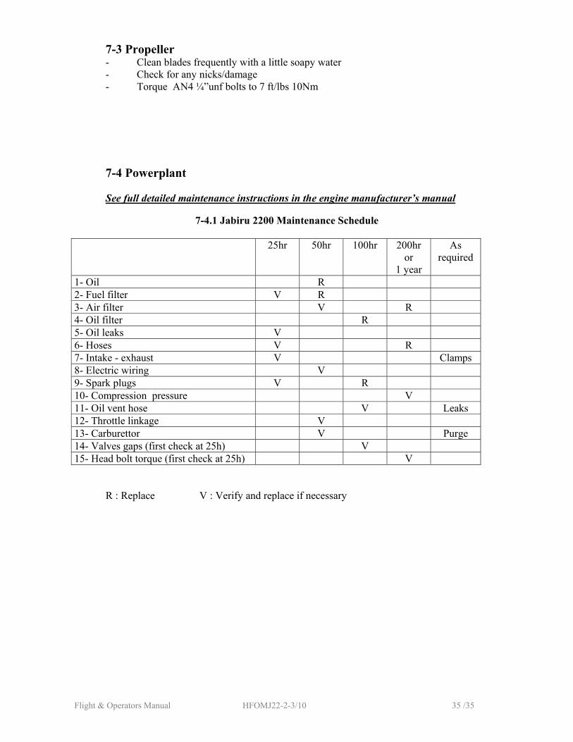
7-3 Propeller - Clean blades frequently with a little soapy water - Check for any nicks/damage - Torque AN4 ¼”unf bolts to 7 ft/lbs 10Nm
7-4 Powerplant
See full detailed maintenance instructions in the engine manufacturer’s manual
7-4.1 Jabiru 2200 Maintenance Schedule 25hr 50hr 100hr 200hr
or 1 year
As required
1- Oil R 2- Fuel filter V R 3- Air filter V R 4- Oil filter R 5- Oil leaks V 6- Hoses V R 7- Intake - exhaust V Clamps 8- Electric wiring V 9- Spark plugs V R 10- Compression pressure V 11- Oil vent hose V Leaks 12- Throttle linkage V 13- Carburettor V Purge 14- Valves gaps (first check at 25h) V 15- Head bolt torque (first check at 25h) V R : Replace V : Verify and replace if necessary