Embed Size (px)
Citation preview

HAZARD ANALYSIS PROCESS FOR AUTONOMOUS VESSELS
Osiris A. Valdez Banda, Aalto University Sirpa Kannos, Novia UAS
Serie R: Rapporter

Osiris A. Valdez Banda, Aalto University Sirpa Kannos, Novia University of Applied Sciences
Hazard Analysis Process for Autonomous Vessels
Utgivare: Yrkeshögskolan Novia, Wolffskavägen 33, 65200 Vasa, Finland © Yrkeshögskolan Novia och Sirpa Kannos, Osiris A. Valdez Banda
Novia Publikation och produktion, serie R: Rapporter 2/2019ISBN 978‐952‐7048‐47‐4 (online)
ISSN 1799‐4179

Sammanfattning:
Eng:
This report introduces a systemic process for an initial hazard analysis in the operative context of autonomous vessels. The process facilitates executing an initial analysis of safety hazards in the earliest design phase before the planning of ship design, materials, structures, components, systems and the services linked to the functioning of an autonomous vessel. The process attempts to produce information to make the systematic integration of safety controls that need to be implemented in an initial safety management strategy.
In this report, the process is applied to analyse the safety hazards in the foreseen functioning of two concepts of autonomous ferries operating in urban waterways in and near the city of Turku in Finland. The process first identifies the main type of accidents and hazards in the operational context of these ferries. It then proposes high‐level safety controls to mitigate the hazards and prevent these accidents. The controls are subsequently used as a basis for developing an initial safety management strategy for autonomous ferries and their operational system. This provides a systematic representation of safety controls in the operative context of autonomous ferries.
The full process is composed of five different steps to elaborate a systematic analysis of hazards and to define safety controls for mitigating and preventing the identified hazards. These controls are the basis of the initial safety management strategy of autonomous vessels and their operational system. This report was done as part of the ÄlyVESI – Smart City Ferries research, development and innovation project.
Smart City Ferries, the ÄlyVESI project, was a conceptualisation, product development and innovation project realised by cities, businesses and universities 1.10.2016 – 31.5.2018. The project explored, developed and tested new technologies and intelligent urban waterborne traffic solutions and services. Novia University of Applied Sciences, Turku University of Applied Sciences, Aalto University and the City of Turku carried out the project in co‐operation. The project was funded by the 6Aika‐program of the European Regional Development Fund. In addition, the project was funded by the Finnish Transport Safety Agency and the cities of Helsinki and Espoo.
Sve:
Denna rapport introducerar en systematisk process för en inledande riskanalys gällande autonoma
fartygs operation. Denna process underlättar utförandet av en inledande analys av säkerhetsrisker i det
tidiga design skedet före planeringen av fartyget, dess material, strukturer, komponenter och system
och de tjänster som är anknutna till hur ett autonomt fartyg fungerar. På basen av denna process
försöker man säkerställa ändamålsenlig information för integreringen av de systematiska
säkerhetskontroller som bör vara implementerade i en inledande säkerhetsstrategi.
I denna rapport tillämpas säkerhetsriskanalysen på två planerade koncept där autonoma färjor opererar
i urbana farvatten i och i närheten av Åbo stad i Finland. Processen identifierar först huvudtyperna av
olyckor och risker i färjornas operativa kontext. Sedan föreslås elementära säkerhetskontroller för att
minska riskerna och undvika olyckor. Kontrollerna tillämpas därefter som en bas för utvecklingen av en

inledande säkerhetsstrategi för autonoma färjor och dessas operativsystem. Detta möjliggör en
systematisk representation gällande säkerhetskontroller för operation av autonoma färjor.
Hela processen består av fem olika steg för att utveckla en systematisk analys av risker och för att
definiera säkerhetskontroller för att minska eller förhindra de identifierade riskerna. Dessa kontroller är
basen för den inledande säkerhetsstrategin för autonoma fartyg och deras operativ system. Denna
rapport är en del av ÄlyVESI‐ Smarta Stadsfärjor forsknings‐, utvecklings‐ och innovationsprojektet.
Smarta Stadsfärjor, ÄlyVESI projektet, var ett konceptifierings‐, produktutvecklings‐ och
innovationsprojekt förverkligat av städer, företag och universitet under tiden 1.10.2016 – 31.5.2018.
Projektet undersökte, utvecklande och testade nya teknologier och intelligent urban sjövägstrafik och
tjänster. Projektet utfördes som ett samarbete mellan Yrkeshögskolan Novia, Turun
Ammattikorkeakoulu, Aalto‐yliopisto och Åbo stad. Projektet finansierades av 6Aika‐programmet och
Europeiska regionala utvecklingsfonden. Därtill finansierades projektet av Trafiksäkerhetsverket och
städerna, Helsingfors och Esbo.
Sök‐ och nyckelord:
Hazards, autonomous vessels, Älyvesi, urban waterways, ferries
Riskfaktorer, autonoma fartyg, Älyvesi, urbana farvatten, färjor

HAZARD ANALYSIS PROCESS FOR
AUTONOMOUS VESSELS
AUTHORS:
Osiris A. Valdez Banda
Aalto University, Department of Applied Mechanics (Marine Technology)
Sirpa Kannos
NOVIA University of Applied Science

1
Table of Contents 1. Introduction .................................................................................................................................... 2
2. Background ..................................................................................................................................... 3
3. Proposed Process for Hazard Analysis ............................................................................................ 4
3.1 Process foundations ...................................................................................................................... 4
3.2 The hazard analysis process .......................................................................................................... 5
3.2.1 Step one: Definition of accidents and identification of hazards: ........................................... 5
3.2.2 Step two: Detailed hazard description and initial definition of mitigation actions: .............. 5
3.2.3 Step three: Definition of the safety controls: ........................................................................ 6
3.2.4 Step four: Identification of unsafe control actions (UCAs) and redefinition of the safety
controls ........................................................................................................................................... 6
3.2.5 Step five: Representation of the initial safety management strategy ................................... 6
4. Process application ......................................................................................................................... 7
4.1 Expert consultation ....................................................................................................................... 7
4.2 Process application outcome ........................................................................................................ 8
4.2.1 Accident types and identification of hazards: step one ......................................................... 8
4.2.2 Steps 2 to 4: detailed hazard description, definition of safety controls, identification of
unsafe control actions (UCAs) and redefinition of the safety controls........................................... 9
Hazard 1. Object detection sensor error ........................................................................................ 9
Hazard 2. Al software failure ........................................................................................................ 13
Hazard 3. Technical fault (e.g. mechanical failure) ....................................................................... 17
Hazard 4. Heavy weather/sea conditions ..................................................................................... 19
Hazard 5. Strong currents ............................................................................................................. 20
Hazard 7. Overloading vessels ...................................................................................................... 28
Hazard 9. Flooding ........................................................................................................................ 33
Hazard 10. Ignition of electrical equipment and wiring ............................................................... 36
Hazard 11. Passenger starting a fire ............................................................................................. 40
Hazard 12. Unintended falling overboard..................................................................................... 43
Hazard 13. Intended jumping overboard ...................................................................................... 43
Hazard 14. Persons getting injured ............................................................................................... 48
Hazard 15. Person(s) medical condition ....................................................................................... 49
4.2.3 The representation of the initial safety management strategy for ferry A and B: step five 54
5. Conclusions ................................................................................................................................... 65
Acknowledgements ............................................................................................................................... 65
References ............................................................................................................................................ 66

2
1. Introduction Autonomous vessels need to operate with the support of entire smart systems (Vermesan and Friess 2013). The industry involved in the development of autonomous vessels is aware about this and are constantly investing to create smart autonomous maritime systems (Teivainen 2017). Safety represents an essential aspect for ensuring the correct functioning of such a system. Autonomous vessels have the initial expectation that they have to be at least as safe as the most advanced manned ships (Rødseth and Burmeister, 2015; Jalonen et al. 2017). ÄlyVESI - Smart City Ferries is an R&D and innovation project between cities, technology companies and universities. The aim is to research and develop new solutions and services for intelligent transport. The project enables companies to develop new business in the marine technology and ICT sectors, at the same time keeping management and design of safety as one of the main priorities. This report introduces a systemic process for an initial hazard analysis in the operative context of autonomous vessels. The process facilitates executing an initial analysis of safety hazards in the earliest design phase before the planning of ship design, materials, structures, components, systems and the services linked to the functioning of an autonomous vessel. The process attempts to produce information to make the systematic integration of safety controls that need to be implemented in an initial safety management strategy. In this report, the process is applied to analyse the safety hazards in the foreseen functioning of two concepts of autonomous ferries operating in urban waterways in and near the city of Turku in Finland. The process first identifies the main type of accidents and hazards in the operational context of these ferries. It then proposes high-level safety controls to mitigate the hazards and prevent these accidents. The controls are subsequently used as a basis for developing an initial safety management strategy for autonomous ferries and their operational system. This provides a systematic representation of safety controls in the operative context of autonomous ferries. The full process is composed of five different steps to elaborate a systematic analysis of hazards and to define safety controls for mitigating and preventing the identified hazards. These controls are the basis of the initial safety management strategy of autonomous vessels and their operational system. This initial safety management strategy provides itemized information that is relevant for planning, designing and constructing autonomous vessels and their entire operational system. The execution of steps one to four produces itemized information that is systematically connected. Step five focuses on representing the main components emerged from the analysis: the hazards, their safety controls, the logic principle of the safety controls, and the link to the accidents that these listed components aim to prevent or respond to. The entire process is described in Section 3.2.

3
2. Background The hazard analysis presented in this study focuses on two specific concepts of autonomous ferries for urban transport. Autonomous ferry “A” This first concept has a mission to transport passengers across the Aura River in the city of Turku. The distance navigated by this ferry is about 100 meters in total. The total passenger capacity for this autonomous ferry is not yet defined but current ferries (man controlled) with similar missions in the same operational area have a maximum capacity of 75 passengers. The operational function of the ferries is described as follows:
a) Passengers board the ferry while she is docked b) The boarding process is finalized
b.1) The access gate on the pier is closed b.2) The access door on the vessel in closed
c) The ferry undocks d) The ferry begins her voyage e) The ferry reaches the other side of the river and docks f) The passengers disembark the ferry (after this is concluded operation “a” is repeated)
Autonomous ferry “B” This second concept has the mission to transport passengers from downtown Turku to the Island of Ruissalo. The ferry will navigate in the river Aura, navigate through a sheltered sea area for a short time, and reach her destination in Ruissalo. The distance navigated is around 8 km. The passenger capacity in this concept has not yet been defined neither, but the estimated passenger capacity is about 120 passengers. The operational function of the ferry is similar to that of ferry “A”.

4
3. Proposed Process for Hazard Analysis
3.1 Process foundations The process of analysis, proposed in this report, is based on a safety engineering approach linked to the System- Theoretic Process Analysis (STPA) included within the Systems-Theoretic Accident Modelling and Processes (STAMP) (Leveson, 2011). STAMP is a new approach to depict and review the function of safety from a systemic perspective. It analyses accidents by making a review of the entire socio-technical system (Chatzimichailidou and Dokas, 2015). STAMP provides a systemic way to model safety for producing a better understanding about how accidents occur and how they can be prevented (Fleming et al., 2013). STAMP promotes hazard analysis that goes beyond component failures. This is supported with the STPA, a hazard analysis technique that identifies accident scenarios that encompass the entire accident process by including design errors, component interactions, and other social, organizational, and management factors in the analysis (Leveson, 2011). Previously, both STAMP and STPA have been satisfactorily applied in the analysis of safety of autonomous systems in other transportation domains such as the automobile and aviation industries (Chen et al. 2015; Hinchman et al. 2012; Oscarsson et al. 2016). The proposed process focuses on defining accidents that can occur in a specific mission and operational context of an autonomous vessel. It identifies and analyses hazards that can lead to defined accidents. The process is extended to incorporate a description of the hazards’ causal factors, and a comprehensive definition and review of potential actions to mitigate the risk. The process includes a systematic representation of safety controls and an initial definition of the safety management strategy. The proposed process for hazard analysis is performed based on the available knowledge, which consists of judgments and assumptions. The purpose is to provide a systematic and itemized initial list of safety controls in order to establish a consistent initial safety management strategy for further development in later design stages.

5
3.2 The hazard analysis process
3.2.1 Step one: Definition of accidents and identification of hazards: Step one defines the types of accidents covered in the analysis. For this purpose, we define the concept of accident in accordance with Valdez Banda and Goerlandt (2017):
Accident represents an undesired and unplanned event that results in a loss and affectations, including loss of human life or injury, property damage, equipment damage or environmental pollution, delays in the system operations and repair costs.
The accident identification consists of specifying the accident types, which may cause the specified effects on the operational functioning of the autonomous vessel. In this initial analysis phase, the identification of accidents focuses on determining and describing the most critical accidents, which the safety controls, and the initial safety management strategy aim to prevent and/or provide a post-accidental response to. The hazard identification focuses on the definition of those hazards, which can lead to the defined accidents. The aim is to detect a certain system state or set of conditions, which in a particular set of worst-case conditions in the operational context, lead to the defined accidents (Leveson, 2011). This enables the development of the initial systematic connection between the accidents and their linked hazards.
3.2.2 Step two: Detailed hazard description and initial definition of mitigation actions: Step two elaborates detailed descriptions and effects of the hazards, providing a comprehensive argumentation about the relevancy of specific hazards, and a qualitative estimation of their potential severity and type of consequences. This step continues with the identification of potential causal factors of the hazard. This describes the hazard as a combination of system state and conditions that could influence the effect of the hazard occurrence. The second step concludes with identifying the possible hazard mitigation actions. This part is essential to represent the initial specifications of the safety controls, which are the core element of the initial safety management strategy (Leveson et al. 2009). These mitigation strategies are flexible to include diverse forms of mitigation actions including for example the implementation of technology, management procedures, reviews, and testing programs. The aim is to create an extensive and coherent list of mitigation actions. At this point, the actions have to be preliminary assessed to estimate the complexity and costs of their actual implementation. Finally, each mitigation action has to be categorized based on their intended mitigation control strategy. For this, the process includes the following four categories:
i. The defined mitigation action attempts to reduce the damage if the accident occurs ii. The defined mitigation action attempts to reduce the likelihood that the hazard results in an
accident. iii. The defined mitigation action attempts to reduce the likelihood that the hazard will occur. iv. The defined mitigation action attempts to completely eliminate the hazard

6
3.2.3 Step three: Definition of the safety controls: Step three focuses on defining safety controls based on the adopted mitigation actions. This task demands the review and prioritization of mitigations actions that will be further developed as the safety controls of the initial safety management strategy. The aim is to assess if the safety controls are objective and relevant before continuing their analysis and development into the initial safety management strategy of the autonomous vessel.
3.2.4 Step four: Identification of unsafe control actions (UCAs) and redefinition of the
safety controls The identification of UCAs and redefinition of the safety controls are executed by following the STPA analysis process. The objective is to analyse each hazard and the safety controls defined to it. The phases of the STPA process are:
a) For each defined safety control, identify unsafe control actions (UCAs) that could lead to a hazardous state in the system. Hazardous states result from inadequate controls or enforcement of the safety control. These can occur because:
- A control action for safety is not provided or followed - An unsafe control action is provided - A safety control is provided too early or too late - A safety control is stopped too soon or applied too long
b) Define why and how UCAs could occur
- Examine the elements included in the functioning of the safety control - Consider how the safety control could degrade over the time
c) The STPA process includes a redefinition of the function of the safety control. The redefinition
states how the safety control mitigates the identified UCAs. This provides a clear definition of the actual logic principle behind the functioning of the safety control.
3.2.5 Step five: Representation of the initial safety management strategy The execution of step one to step four produce itemized information that is systematically connected. Step five focuses on representing the main components emerged from the analysis: the hazards, their safety controls, the safety controls logic principle, and the link to the accidents that these listed components aim to prevent or respond to. This step provides a detailed representation of the initial safety management strategy of the autonomous vessel.

7
4. Process application
4.1 Expert consultation In order to apply the proposed process to analyse the hazards of the described Ferry A and B, experts
in different industry domains were consulted. Appendix 1 describes the background and expertise
areas for each participating expert.
Initially, two experts (experts A and B) executed steps one and two of the process, which produced
preliminary information for the following steps.
A group of experts, with specialization and knowledge in fields relevant to the initial hazard mitigation
actions recognized in steps one and two, continued the process. They executed steps three and four
in four separate workshops. In the workshops, preliminary information was validated and analysed
further.
Step five was executed by one expert (expert B). Expert B compiled the information gathered in the
process to a representation of the initial safety management strategy. Table 1 presents the tasks given
for the experts in in process application.
Table 1. Task descriptions for the experts
Process Step
Task
One Define accidents and identify the hazards that can lead to them:
• Are the defined accidents the most relevant for analysis?
• Is the list of identified hazards complete?
Two a) Execute STAMP preliminary hazard analysis for each hazard identified in step one b) Review the preliminary hazard analysis by answering the following questions:
• Is the hazard description relevant and accurate?
• Is the list of the causal factors sensible?
• Are the mitigation actions relevant?
• Is there any other mitigation action to be included?
• Do you agree with the scales given to the cost/difficulty and the categorization of the mitigation control actions?
Three Based on the mitigation actions, define which of these should be further analysed and redefined as safety controls.
Four STPA implementation a) Define potential unsafe control actions for each safety control. Consider the following aspects:
• The function of the safety control is not provided and/or enough
• The provision of the safety control’s function is wrong
• The function of the safety control is provided at the wrong time
• The function of the safety control is provided for too long or too short b) Define the potential causes of the unsafe controlled actions (UCAs) c) Redefine the safety control and specify how it mitigates the hazard and the defined UCAs
Five Representation of the initial safety management strategy

8
4.2 Process application outcome
4.2.1 Accident types and identification of hazards: step one
Accident Hazards
1. Allision with a pier H1. Object detection sensor error H2. Al software failure H3. Technical fault (e.g. mechanical failure) H4. Heavy weather/sea conditions H5. Strong currents H6. Position reference equipment failure
2. Collision with a moving object
2.1 Collision with another vessel H1. Object detection sensor error H2. Al software failure H3. Technical fault (e.g. mechanical fault)
2.2 Collision with a small moving target (e.g. canoe, SUP-board, etc.)
H1. Object detection sensor error H2. Al software failure H3. Technical failure (e.g. mechanical failure)
3. Collision with a fixed object (e.g. buoys, beacons, etc.)
H1. Object detection sensor error H2. Al software failure H3. Technical fault (e.g. mechanical failure) H4. Heavy weather/sea conditions H5. Strong currents H6. Position reference equipment failure
4. Grounding H2. AI software failure H3. Technical failure (e.g. mechanical failure) H6. Position reference equipment failure H4. Heavy weather/sea conditions H5. Strong currents
5. Bottom touch H2. AI software failure H3. Technical failure (e.g. mechanical failure) H6. Position reference equipment failure H4. Heavy weather/sea conditions H5. Strong currents
6. Capsizing/ Sinking H7. Overloading of the vessel H8. Shifting of weights H9. Flooding
7. Fire on board H10. Ignition of electrical equipment or wiring H11. Passenger starting a fire
8. Man over board H12. Unintended falling overboard H13. Intended jumping overboard
9. Medical emergency on board H14. Person(s) getting injured H15. Person(s) medical condition
10. Medical emergency on pier H14. Person(s) getting injured H15. Person(s) medical condition

9
4.2.2 Steps 2 to 4: detailed hazard description, definition of safety controls, identification
of unsafe control actions (UCAs) and redefinition of the safety controls
Hazard 1. Object detection sensor error Hazard H1. Object detection sensor error
Hazard effect/ description
Provide extra details regarding the designated severity rating In case of object detection sensor error, the information about objects around the vessel is not reliable and thus the vessel may not be able to navigate safely and avoid collisions with moving objects according to the rules of the road or collisions with fixed objects. This hazard may not affect the ship operation significantly in most cases, but in a more severe scenario, the hazard can have a negative impact on people, property, and environment. It can result in injuries, loss of human life, severe damage or loss of property (own and others property) and environmental effects such as oil spills or other damage of sensitive sea areas.
Causal factors Describe the hazard as system state. What conditions could influence the effect of the hazard occurrence? - Loss of power - Equipment malfunction - Dirt - Icing - Overheating - Equipment interference - Inappropriate maintenance - Incorrect sensor set and/or positioning of the sensors - Targets impossible to detect - Interference - Corrupted readings - Complete equipment failure
Mitigation strategy
- Sensor system redundancy and diversity - UPS (Uninterrupted Power Source) - Appropriate heating, cooling and cleaning systems - Thorough commissioning of equipment set - Appropriate and continuous maintenance program - Continuous system diagnosis and proof testing - Autonomous Integrity monitoring
Cost/Difficulty High Low
Medium Medium
Low Low Low
Priority (1-4) * 4 3 3
3/4 3 3 2
*Mitigation priority scale
Level
4
3
2
1
Description Eliminate Prevent Control Reduce
Detailed description Complete elimination of the hazard Reduction of the likelihood that the hazard will occur Reduction of the likelihood that the hazard results in an accident Reduction of the damage if the accident occurs
STPA Analysis
(1) Safety control
SC 1. Sensor system redundancy and diversity SC 2. UPS (Uninterrupted Power Source) SC 3. Appropriate heating, cooling, and cleaning systems SC 4. Thorough commissioning of equipment set SC 5. Appropriate and continuous on board maintenance program SC 6. Continuous system diagnosis and proof testing SC 7. Autonomous Integrity monitoring
(2) Detecting potentially Unsafe Controlled Actions (UCAs) and (3) redefining the safety control
SC 1 Sensor system redundancy and diversity

10
UCA 1. Sensor does not function properly and there is no other sensor available Potential causes - Lack of economic resources UCA 2. Equipment chosen to provide the redundancy are not suitable Potential causes - Lack of economic resources - Lack of knowledge of sensors characteristics when planning the equipment set needed
UCA 3. Sensor failure is not detected Potential causes - Sensor diagnosing does not cover all necessary areas
UCA 4. External or common cause failure takes several equipment down at the same time Potential causes - Inappropriate system design - Incorrect installation - Incorrect usage - Environmental conditions Redefining of the safety control Sensor system redundancy and diversity: - If one sensor fails the redundancy ensures there will be another sensor functioning - Equipment chosen to provide the redundancy have to be the correct ones in order to provide the user with the
required information at all times
SC 2 UPS (Uninterrupted Power Source) UCA 1. There is a disturbance in the vessel’s power system and the equipment is not backed up with UPS Potential causes - Lack of economic resources - Lack of understanding of the importance of the UPS
UCA 2. The UPS does not work Potential causes - UPS is not charged - UPS is not connected correctly - UPS is broken
UCA 3. The UPS takes too long to switch on Potential causes - Errors in UPS function UCA 4. The capacity of the UPS is not sufficient to provide power for the equipment as long as needed or the capacity in terms of power and/or energy of the UPS is exceeded Potential causes - The disturbance lasts longer than was expected in the planning stage - Wrong type of UPS Redefining of the safety control UPS (Uninterrupted Power Source): - If there is a disturbance in the vessel’s power system the UPS can temporarily provide power for the critical
equipment - When the UPS setup is planned, installed and maintained properly, the user can count on a reliable backup
system
SC 3 Appropriate heating, cooling and cleaning systems UCA 1. Equipment is not able to function properly in winter conditions Potential causes - Equipment does not have heating function

11
- Extremely low temperatures - Icing UCA 2. Equipment is not able to function properly due to high temperatures Potential causes - Equipment does not have cooling function - Extremely high temperatures - The systems are located close to heat sources UCA 3. Equipment lens is dirty Potential causes - Sea water spray - Bird feces UCA 4. Condensation inside equipment Potential causes - Leakage - Temperature changes - Fault on the equipment design - Humid climate - Location on-board Redefining of the safety control Appropriate heating, cooling and cleaning systems:
- By applying sensors with proper heating and/or cooling systems it can be ensured that they function properly in all operating conditions
- By applying sensors with automatic cleaning systems it can be ensured that they function properly outdoors
SC 4 Thorough commissioning of equipment set UCA 1. The equipment set has not been properly tested or not tested at all before operation Potential causes - Lack of economic resources - Test plan is not appropriate - Lack of time Redefining of the safety control Thorough commissioning of equipment set: - When the equipment set is thoroughly tested and certified (preferably by an independent body) it ensures that
the equipment function properly, are compatible and the operation can be run safely.
SC 5 Appropriate and continuous on board maintenance program UCA 1. There is no on board maintenance program Potential causes - Lack of economic resources - Lack of understanding of the importance of the maintenance program UCA 2. The maintenance program does not cover the necessary elements and the life cycle of the hardware. Potential causes - Lack of competence UCA 3. The maintenance program is not followed Potential causes - Lack of time (work overload) - Lack of economic resources - Lack of understanding of the importance of the maintenance program UCA 4. Maintenance is not done properly Potential causes

12
- Lack of commitment - Lack of competence - Human error or mistake - Lack of economic resources Redefining of the safety control Appropriate and continuous maintenance program: - By implementing an on board maintenance program it can be ensured that all critical systems remain functional
at all times - A well planned maintenance program covers all necessary areas on board and it is adjusted separately for each
vessel - Maintenance done timely and accordingly to the program by competent personnel ensures smooth operation
of the sensors
SC 6. Continuous system diagnosis and proof testing UCA 1. There is no continuous system diagnosis and proof testing Potential Causes - Lack of economic resources - Lack of planning - It cannot be performed due to the effects on operation UCA 2. The continuous system diagnosis and proof testing do not cover all necessary functions Potential causes - Lack of economic resources - Lack of planning - Tests cannot be performed due to the effects on operation UCA 3. The test is not able to recognize problems Potential causes - Wrong test design - Changes in the system Redefining of the safety control: Continuous system diagnosis and proof testing: - Continuous system diagnosis and regular proof testing ensure that the system functions as it should - Test design should be planned carefully and updated after changes in the system in order to cover all the
necessary functions and recognize potential problems - Possible effect on the operation should be taken into account in planning
SC 7. Autonomous Integrity monitoring UCA 1. There is no integrity monitoring Potential causes - Lack of economic resources - Lack of planning - Lack of understanding UCA 2. Integrity monitoring gives wrong information Potential Causes - Common cause failure - Wrong design - Changes in the system Redefining of the safety control: Autonomous Integrity monitoring: - Well designed and up to date integrity monitoring systems ensure that the data used has not been damaged or manipulated

13
Hazard 2. Al software failure Hazard H2. AI software failure
Hazard effect/ description
Provide extra details regarding the designated severity rating In case of an AI software failure a vessel may not be able to navigate safely or follow the rules of the road. AI failure may lead to collision, allision, grounding or bottom touching. The hazard can have a negative impact on people, property, and environment. It can result in injuries, loss of human life, severe damage or loss of property (own and other people’s property) and environmental effects such as oil spills or other damage of sensitive sea areas.
Causal factors Describe the hazard as system state. What conditions could influence the effect of the hazard occurrence? - Architecture design failure - Coding error in algorithm/algorithms - Error in algorithm specifications - Situation unknown to AI - Loss of power - Overheating - Inappropriate maintenance - Software update - Error in learning data - Misleading safety function requirement - Changes in the system - Computer failure
Mitigation strategy - Thorough planning, testing and commissioning of
AI software - Computer and software redundancy - UPS (Uninterrupted Power Source) - Appropriate cooling for computers - Appropriate and continuous on board
maintenance programs - Robust system design - Appropriate system (software) design and
maintenance processes
Cost/Difficulty High
Low Low Low Low
High High
Priority (1-4) * 4
3 3 3 3
4 3
*Mitigation priority scale Level
4 3 2 1
Description Eliminate Prevent Control Reduce
Detailed description Complete elimination of the hazard Reduction of the likelihood that the hazard will occur Reduction of the likelihood that the hazard results in an accident Reduction of the damage if the accident occurs
STPA Analysis:
(1) Safety control
SC 1. Thorough planning, testing and commissioning of AI software SC 2. Computer and software redundancy SC 3. UPS (Uninterrupted Power Source) SC 4. Appropriate cooling for computers SC 5. Appropriate and continuous on board maintenance programs SC 6. Robust system design SC 7. Appropriate system (software) design and maintenance processes
(2) Detecting potentially Unsafe Controlled Actions (UCAs) and (3) redefining the safety control
SC 1 Thorough planning, testing and commissioning of AI software UCA 1. Thorough planning, testing and commissioning of AI are not done Potential causes - Lack of economic resources - Lack of time

14
- Lack of competence UCA 2. Insufficient planning, testing and commissioning of AI Potential causes - Poor knowledge of operational conditions - Lack of economic resources - Lack of time - Lack of competence Redefining of the safety control Thorough planning, testing and commissioning of AI: - Thorough planning, testing and commissioning of AI software ensure that the software is robust and free of
errors - Applicable standards should be followed
SC 2 Computer and software redundancy UCA 1. Computer breaks down and there is no computer and software redundancy Potential causes - Lack of economic resources - Lack of space - Poor design of the system UCA 2. Secondary computer does not take over in case of a failure Potential causes - Signalling error - No physical connection between computers - Malfunction of the secondary computer - Primary computer does not successfully pass the information to the secondary computer to take over - No physical connection between computers Redefining of the safety control Computer and software redundancy: - Computer and software redundancy ensure availability of the AI functions at all times
SC 3 UPS (Uninterrupted Power Source) UCA 1. There is a disturbance in the vessel’s power system and the AI system is not backed up with UPS Potential causes - Lack of economic resources - Lack of understanding of the importance of the UPS
UCA 2. The UPS does not work Potential causes - UPS is not charged - UPS is not connected correctly - UPS is broken
UCA 3. The UPS takes too long to switch on Potential causes - Errors in UPS function
UCA 4. The capacity of the UPS is not sufficient to provide power for the AI system as long as needed or the capacity in terms of power and/or energy of the UPS is exceeded Potential causes - The disturbance lasts longer than expected in the planning stage - Wrong type of UPS Redefining of the safety control UPS (Uninterrupted Power Source): - If there is a disturbance in the vessel power system the UPS can temporarily provide power for the critical
equipment

15
- When the UPS-setup is planned, installed and maintained properly, the user can count on a reliable backup system
SC 4 Appropriate cooling for computers UCA 1. Computer does not function reliably due to overheating. Potential causes - The cooling is not adequate - The cooling is broken - Wrong location of the computer (limited space and inappropriate conditions) - Loss of power Redefining of the safety control Appropriate cooling for computers: - In order to function properly all computer components must be kept within permissible operating temperature
limits - Cooling systems should be selected carefully. Both the waste heat produced by the computer components and
possible external heat sources should be taken in to account.
SC 5 Appropriate and continuous on board maintenance programs UCA 1. There is no on board maintenance program Potential causes - Lack of economic resources - Lack of understanding of the importance of the maintenance program
UCA 2. The maintenance program does not cover the necessary elements and the life cycle of the hardware. Potential causes - Lack of competence
UCA 3. The maintenance program is not followed Potential causes - Lack of time (work overload) - Lack of economic resources - Lack of understanding of the importance of the maintenance program
UCA 4. Maintenance is not done properly Potential causes - Lack of commitment - Lack of competence - Human error or mistake - Lack of economic resources
UCA 5. Software updates are not done and the system is not capable to correct detected issues Potential causes - Lack of time - Lack of commitment - Lack of competence - Human error or mistake UCA 6. Software update creates an inappropriate function in the system Potential causes - Wrong settings in the software for the update - Errors in the update - Changes in the interface of the equipment or software modules UCA 7. Software and hardware do not match Potential causes - Configuration management issues - Interrupted update process Redefining of the safety control

16
Appropriate and continuous on board maintenance programs: - By implementing an on board maintenance program it can be ensured that all critical systems remain functional
at all times - A well planned maintenance program covers all necessary areas on board and it is adjusted separately for each
vessel - Maintenance done timely and accordingly to the program by competent personnel ensures smooth operation - Special attention should be paid not only to the properly timed software updates but also to the updating
process.
SC 6. Robust system design UCA 1. Without robust system design it is not possible to detect and cope with poor and/or missing data Potential causes - Lack of economic resources - Lack of commitment - Lack of competence - Failure modes are not taken into account
UCA 2. Single point failure takes the whole system down Potential causes - Lack of system understanding - Failure modes are not taken into account Redefining of the safety control Robust system design: - Robust system design should be able to isolate failures in the system and allow for the rest of the system to
continue operating.
SC 7. Appropriate system (software) design and maintenance processes UCA 1. User requirements are not known or taken into account and the final product is not the expected. Potential causes - Poor communication between customer and developer - Customer is not competent to define needs - Lack of time - Lack of interest UCA 2. System requirements are not clear for the developers and do not cover relevant issues Potential causes - Poor documentation - Poor communication between developers and sales people UCA 3. System design does not meet expectations Potential causes - Poor documentation - Poor communication - The design is not reviewed
UCA 4. System implementation does not meet expectations Potential causes - Poor documentation - Missing review of the implementation - Human coding error - Poor or missing testing
UCA 5. Software is not verified properly Potential causes - Customer and system requirements cannot be compared due to poor documentation - Lack of time - Lack of economic resources UCA 6. Change management is not working properly

17
Potential causes - Change requirements are not communicated properly - Effect analysis of changes is not performed Redefining of the safety control Appropriate system (software) design and maintenance processes: - Ensure that the system meets customer’s expectations - Requires good communication between customer, sales people and developers, but also good documentation - Special attention should be paid to reviews throughout the process and software verification at the end - Change management must not be forgotten
Hazard 3. Technical fault (e.g. mechanical failure) Hazard H3. Technical fault (e.g. mechanical failure)
Hazard effect/ description
Provide extra details regarding the designated severity rating In case of technical fault, the vessel may e.g. lose her steering or propulsion power that may lead to collision with a moving or fixed object, allision with a pier, grounding or bottom contact. The hazard can have a negative impact on people, property and environment. It can result in injuries, loss of human life, severe damage or loss of property (own and others property) and environmental effects such as oil spills or other damage of sensitive sea areas.
Causal factors Describe the hazard as system state. What conditions could influence the effect of the hazard occurrence? - Inappropriate maintenance - Manufacturing defect - Incorrect technical design - Vandalism
Mitigation strategy
- Redundancy of critical systems - Thorough planning, testing and commissioning of
all technical systems - Appropriate and continuous maintenance
programs - Distance monitoring and fault detection of the
technical systems
Cost/Difficulty
High High
Low
High
Priority (1-4) *
4 4
3
3
*Mitigation priority scale Level
4
3
2
1
Description Eliminate Prevent Control Reduce
Detailed description Complete elimination of the hazard Reduction of the likelihood that the hazard will occur Reduction of the likelihood that the hazard results in an accident Reduction of the damage if the accident occurs
STPA Analysis:
(1) Safety controls
SC 1. Redundancy of critical systems SC 2. Thorough planning, testing and commissioning of all technical systems SC 3. Planned and predictive maintenance programs SC 4. Remote monitoring and fault detection of technical systems
(2) Detecting potentially Unsafe Controlled Actions (UCAs) and (3) redefining the safety controls
SC 1. Redundancy of critical systems UCA 1. There is no redundancy for critical systems and any single failure can cause vessel operation to stop Potential causes - Lack of resources - Lack of competence - Poor planning

18
UCA 2. The critical equipment have not been identified correctly Potential causes - Lack of resources - Lack of competence - Poor planning UCA 3. Critical systems have been changed without proper analysis of the effects on the system Potential causes - Lack of change management - Lack of economic resources - Lack of time - Lack of competence - Lack of spare parts available - Poor documentation Redefining of the safety control Redundancy of critical systems: - With redundancy in the systems the effect of a single failure can be minimized - Redundancy and system integration should be taken into account already in the planning stage - Proper testing and commissioning of the systems verifies that all critical systems have been identified - Changes in the system should be managed with a proper protocol/ process
SC 2. Thorough planning, testing and commissioning of all technical systems UCA 1. Autonomous operations have not been taken into account in the whole system design Potential causes - Lack of economic resources - Lack of knowledge and experience - Lack of system integration UCA 2. The tests fail to recognize the problem or potential fault in the systems Potential causes - Lack of knowledge of operational conditions - Only subsystems have been tested UCA 3. The commissioning is not done thoroughly Potential causes - Lack of time - Lack of economic resources - Lack of supervision on client’s side - Lack of knowledge and experience - Poor documentation Redefining of the safety control Thorough planning, testing and commissioning of all technical systems: - The process should be done in good cooperation with designers, buyers, builders, suppliers and regulators. The
autonomous status of the vessel should be taken into account throughout the process - New and efficient practices for commissioning and testing of autonomous vessel systems should be developed
in cooperation with the relevant stakeholders
SC 3. Planned and predictive maintenance programs UCA 1. The system fails due to the lack of maintenance Potential causes - There is no maintenance program - The maintenance program is not followed - Lack of economic resources UCA 2. The maintenance done is not of the right type or it is done poorly Potential causes - Lack of knowledge about the system

19
- Lack of commitment UCA 3. Maintenance programs fail to take into account interaction between systems Potential causes - Poor planning - Lack of knowledge about the system connections
Redefining of the safety control Planned and predictive maintenance programs: - With proper maintenance programs the safety of the vessel can be ensured, the number of technical faults
minimized and the life cycle of technical systems maximized - Maintenance programs have to take into account the system interactions
SC 4. Distance monitoring and fault detection of technical systems UCA 1. Without distance monitoring and fault detection technical faults will not be detected Potential causes - Lack of money - Lack of trust on distance operations UCA 2. Distance monitoring and/or fault detection of technical systems do not work Potential causes - Electromagnetic noise - Poor quality of the data - Quality of the data is not monitored - Failure in the data link on-board and/or ashore Redefining of the safety control Distance monitoring and fault detection of technical systems: - The safe and effective operation of an autonomous vessel requires distance monitoring and fault detection.
Remote monitoring increases the reliability of the operation and reduces off hire time - Without proper monitoring of the data quality, distant monitoring and fault detection systems cannot produce
reliable information
Hazard 4. Heavy weather/sea conditions Hazard H4. Heavy weather/sea conditions
Hazard effect/ description
Provide extra details regarding the designated severity rating If the weather or sea conditions caused by wind, gusts, waves, swell, thunder or weather fronts are too heavy for the vessel she may come to the limits of her ability to manoeuvre and steer in a controlled way. This may lead to collision with a fixed object, allision with a pier, grounding or bottom contact. The hazard can have a negative impact on people, property and environment. It can result in injuries, severe damage or loss of property (own and others property) and environmental effects such as oil spills or other damage of sensitive sea areas.
Causal factors Describe the hazard as system state. What conditions could influence the effect of the hazard occurrence? - Unexpected change of conditions - Lack of operational limits or incorrect operational limits - Weather and sea conditions have not been monitored properly - Local conditions differ from the surrounding areas - Inaccurate weather forecasts - Ice conditions
Mitigation strategy
- Correctly set and followed operational limits - Weather routing and constant weather and sea
state monitoring - Vessels equipped with adequate environmental
sensors for detecting local conditions
Cost/Difficulty
Low
Medium
Priority (1-4) *
4
3

20
- Keeping vessels steady against the wind and waves or heading to an emergency harbour or anchorage
- Constant monitoring and predictions of vessels’ capability
Medium
Low
Medium
3
2
2 *Mitigation priority scale Level
4
3
2
1
Description Eliminate Prevent Control Reduce
Detailed description Complete elimination of the hazard Reduction of the likelihood that the hazard will occur Reduction of the likelihood that the hazard results in an accident Reduction of the damage if the accident occurs
Hazard 5. Strong currents Hazard H5. Strong currents
Hazard effect/ description
Provide extra details regarding the designated severity rating Strong currents affect vessels’ steering, especially when manoeuvring with slow speed. This may lead to allision with a pier or collision with a fixed object. In some cases it may also lead to grounding or bottom contact. The hazard can have negative impact on people, property and environment. It can result in injuries, severe damage or loss of property (own and others property) and environmental effects such as oil spills or other damage of sensitive sea areas.
Causal factors Describe the hazard as system state. What conditions could influence the effect of the hazard occurrence? - Lack of knowledge of local currents in rivers and archipelagos - Lack of monitoring the current effecting the vessel and taking it into account
Mitigation strategy - Knowledge of local currents - Constant monitoring of the current and adjusting
the steering accordingly - Constant monitoring and predictions of vessels’
capability
Cost/Difficulty
Low
Medium
Medium
Priority (1-4) *
2
2
2
*Mitigation priority scale Level
4
3
2
1
Description Eliminate Prevent Control Reduce
Detailed description Complete elimination of the hazard Reduction of the likelihood that the hazard will occur Reduction of the likelihood that the hazard results in an accident Reduction of the damage if the accident occurs
STPA Analysis (combines hazards 4 and 5):
(1) Safety controls
SC 1. Correctly set and followed operational limits SC 2. Weather routing and constant weather and sea state monitoring SC 3. Vessel equipped with adequate environmental sensors for detecting local conditions SC 4. Keeping the vessel steady against the wind and waves or heading to an emergency harbour or anchorage SC 5. Knowledge of local currents and other local environmental conditions SC 6. Constant monitoring of the currents and adjusting the steering accordingly SC 7. Constant monitoring and predictions of vessels capability
(2) Detecting potentially Unsafe Controlled Actions (UCAs) and (3) redefining the safety controls
SC 1. Correctly set and followed operational limits UCA 1. Shipping company has not set operational limits for the vessel Potential causes

21
- Lack of competence- Lack of understanding the importance of setting the operational limits- Lack of control measures for ensuring that the limits are programmed to the system
UCA 2. Operational limits set by the shipping company are too high for the safe operation of the vessel Potential causes - Lack of competence- Lack of information about vessel’s features- Pressure from outside the shipping company- Lack of external verification- Company takes intended risk
UCA 3. Operational limits set for the vessel are not followed Potential causes - Error in detecting the conditions affecting vessel- Error in algorithms- Pressure from outside the shipping company- Lack of monitoring from the remote monitoring centre
Redefining of the safety control Correctly set and followed operational limits: - Permanent operational limits set by the shipping company and acknowledged by all the parties involved, ensure
that the operations are stopped before the safety of a vessel is compromised- Correct operational limits can be determined by considering vessels’ features, capability to manoeuvre and
operating areas- If limits and automatic procedures - for cases when limits are crossed - are programmed in the vessel systems,
the limits are followed without the need to make decisions case by case. Thus decision making is not exposedto human error
- Sending an alarm to the remote monitoring centre - when limits are crossed – acts as a double check, ensuringthat the vessel has time to cease her operations safely
SC 2. Weather routing and constant weather and sea state monitoring
UCA 1. Environmental conditions are not taken into account when planning vessels’ routes - Lack of competence- Lack of information about the conditions affecting vessels en route
UCA 2. Weather and sea state are not constantly monitored when the vessel is in operation - Lack of economic resources- Lack of understanding of the importance of the environmental information- Lack of equipment- Information is not received from local environmental sensors or the information is not correct
UCA 3. Vessel’s route is not changed accordingly when environmental conditions require doing so - Error in detecting the conditions affecting the vessel- Error in algorithms- Lack of monitoring- Used weather forecasts used are not reliable
Redefining of the safety control Weather routing and constant weather and sea state monitoring: - Checking the weather forecasts should always be part of the route planning. Checking the forecast automatically
against the plan (also in the permanent routes between two points) every time before departure ensures vesselsafety
- Constant automatic monitoring of the weather forecasts as well as the local real-time weather data during thetrip ensure the safety along the whole way. Receiving weather forecast from more than one source givesredundancy and allows comparison
- With pre-planned alternative routes programmed to the system, vessels can automatically be safely re-routedif necessary. Re-routing functions should always be properly tested in the commissioning stage.
SC 3. Vessels equipped with adequate environmental sensors for detecting local conditions

22
UCA 1. Vessels are not equipped with adequate and appropriate sensors for monitoring the conditions around them - Lack of economic resources - Lack of knowledge of sensor characteristics or of understanding the needs when planning the sensor set for
vessels - The sensors chosen are not planned to be used in cold climates - Lack of guidance (regulations)
UCA 2. There is not enough redundancy in environmental sensors - Lack of economic resources - Lack of competence Redefining of the safety control Vessels equipped with adequate environmental sensors for detecting local conditions: - With proper equipment on board (or along the route), vessels are able to react also to sudden local changes in
the conditions - In winter conditions proper and reliable operation can be guaranteed if local needs and equipment
characteristics as well as redundancy needs, are considered carefully already when planning the vessel.
SC 4. Keeping the vessel steady against the wind and waves, heading to an emergency harbour or anchoring UCA 1. In case the weather/sea conditions change suddenly over the operational limits, the vessel continues on her route normally instead of choosing a safer option for the situation Potential causes - There are no emergency harbours programmed in the system - Lack of monitoring the environmental conditions - Lack of monitoring from the remote monitoring centre - It is safer to continue Redefining of the safety control Keeping the vessel steady against the wind and waves, heading to an emergency harbour or anchoring : - If an unexpected weather change makes continuing on the route unsafe, automatic route specific contingency
actions (such as driving with minimum manoeuvring speed against the wind etc. or re-routing the vessel to a suitable emergency harbour) programmed to the system are necessary precautions
SC 5. Knowledge of local currents and other local environmental conditions UCA 1. Information about local currents and local environmental conditions in rivers and archipelagos have not been gathered Potential causes - Lack of competence - Lack of existing information or up to date information - Lack of commitment
UCA 2. Information about local currents and local environmental conditions have not been taken into account when planning vessel routes Potential causes - Lack of competence - Lack of commitment Redefining of the safety control Knowledge of local currents and other local environmental conditions: - Available information about the local currents and frequent weather conditions is a valuable tool when planning
the vessel and her routes. Especially in archipelagos, lakes and rivers there can be strong local currents, places where fog regularly forms or where the wave height rises above the normal level
SC 6. Constant monitoring of the current and adjusting the steering accordingly UCA 1. There is no equipment available to monitor the current in real time Potential causes - Lack of economic resources - Lack of suitable equipment in the market - There is no actual need to measure the current

23
UCA 2. Current monitoring system does not function correctly Potential causes - Lack of maintenance - Error in equipment UCA 3.Current monitoring information is not connected to the AI and steering equipment Potential causes - Lack of economic resources UCA 4. The reaction time to drifting is too long Potential causes - Error in programming - Lack of competence Redefining of the safety control Constant monitoring of the current and adjusting the steering accordingly: - Vessels reliably equipped to monitor real time currents and to automatically adjust the steering accordingly,
without delays, are able to manoeuvre and dock safely and smoothly
SC 7. Constant monitoring and predictions of vessel capability UCA 1. Vessel capability is not monitored Potential causes - Lack of economic resources - Lack of competence - Lack of commitment UCA 2. Information of the vessel capability is not used to adjust the operational limits or the operation Potential causes - Lack of economic resources - Lack of competence - Lack of commitment Redefining of the safety control Constant monitoring and predictions of vessel capability: - With constant monitoring and predictions of vessel capability, vessels are able to adjust operational limits and
operation in general when necessary. There might be external or internal factors that require lowering the operational limits temporarily
Hazard 6. Position reference equipment failure
Hazard H6. Position reference equipment failure
Hazard effect/ description
Provide extra details regarding the designated severity rating If the position reference equipment fail or give incorrect information, vessels cannot navigate safely. This may lead to allision with pier or collision with a fixed object, grounding or bottom touching. The hazard can have a negative impact on people, property, and environment. It can result in injuries, severe damage or loss of property (own and others property) and environmental effects such as oil spills or other damage of sensitive sea areas.
Causal factors Describe the hazard as system state. What conditions could influence the effect of the hazard occurrence? - Loss of power - Intentional satellite position system jamming - Unintentional satellite positioning jamming - Satellite position system spoofing - Poor satellite availability - Effect of rain etc. on local position reference systems - Dirt (on local position system sensor)

24
- Equipment malfunction - Inappropriate maintenance
Mitigation strategy - Equipment (sensor) redundancy - Combination of local and satellite position
reference systems - Satellite positioning equipment with jamming
detection and/or anti-jamming function - UPS (Uninterrupted Power Source) - Appropriate heating, cooling and cleaning for
local position reference systems - Thorough installation and commissioning of
equipment set - Appropriate and continuous on board
maintenance programs - Continuous system diagnosis and proof testing - Autonomous integrity monitoring
Cost/Difficulty High High
Low
Low
Medium
Medium
Low
Low Low
Priority (1-4) * 4 2
3
3 3
3/4
3
3 2
*Mitigation priority scale
Level
4
3
2
1
Description Eliminate Prevent Control Reduce
Detailed description Complete elimination of the hazard Reduction of the likelihood that the hazard will occur Reduction of the likelihood that the hazard results in an accident Reduction of the damage if the accident occurs
STPA Analysis:
(3) Safety control
SC 1. Equipment (sensor) redundancy SC 2. Combination of local and satellite position reference systems SC 3. Satellite positioning equipment with jamming detection and/or anti-jamming function SC 4. UPS (Uninterrupted Power Source) SC 5. Appropriate heating, cooling and cleaning for local position reference systems SC 6. Thorough installation and commissioning of equipment set SC 7. Appropriate and continuous on board maintenance program SC 8. Continuous system diagnosis and proof testing SC 9. Autonomous Integrity monitoring
(4) Detecting potentially Unsafe Controlled Actions (UCAs) and (3) redefining the safety control
SC 1 Equipment (sensor) redundancy UCA 1. Sensor does not function properly and there is no redundancy in the system
Potential causes
- Lack of economic resources
- Poor planning
UCA 2. Sensor failure is not detected due to the lack of information from other equipment to be compared with Potential causes
- Lack of economic resources
- Poor planning
UCA 3. External or common cause failures take several equipment down at the same time
Potential causes
- Inappropriate system design
- Incorrect installation
- Incorrect usage
- Environmental conditions
Redefining of the safety control

25
Equipment (sensor) redundancy - If one sensor fails the redundancy ensures there is another sensor functioning - System design must have adequate diagnosis function in order to recognize sensor failures and perform the
switch over procedure when necessary - Equipment used to provide redundancy should be completely independent from one another to reduce the risk
of a common cause failure taking them down at the same time
SC 2 Combination of local and satellite position reference systems UCA 1. Positioning is based on satellite positioning only and vessels e.g. lose position because of satellite system failures or poor satellite availability Potential causes - Lack of economic resources - Inappropriate system design UCA 2. Satellite positioning reference equipment give incorrect information and there is no local positioning information to compare it with Potential causes - Lack of economic resources - Inappropriate system design UCA 3. Positioning is based on local position reference systems only and vessels e.g. lose position due to poor weather conditions - Lack of economic resources - Inappropriate system design Redefining of the safety control Combining different types of local and satellite position reference systems: - Using a combination of local and satellite position reference systems provides reliable position information in
different conditions and locations - Helps to detect possible errors in the information
SC 3. Satellite positioning equipment with jamming detection and/or anti-jamming function UCA 1. Vessel loses her position due to jamming Potential causes - Lack of economic resources - Lack of certified equipment in the market UCA 2. Vessel receives wrong or inaccurate position information due to jamming Potential causes - Lack of economic resources - Lack of certified equipment in the market Redefining of the safety control Satellite positioning equipment with jamming detection and/or anti-jamming function - Jamming detection ensures that the jamming is noticed and users can switch to local position reference systems - An anti-jamming function reduces the risk of losing position or receiving wrong/inaccurate position information
due to GPS jamming
SC 4 UPS (Uninterrupted Power Source) UCA 1. There is a disturbance in a vessel’s power system and the equipment is not backed up with UPS Potential causes - Lack of economic resources - Lack of understanding of the importance of the UPS
UCA 2. The UPS does not work Potential causes - UPS is not charged - UPS is not connected correctly - UPS is broken

26
UCA 3. It takes too long for the UPS to switch on and the GPS equipment needs to reacquire the position fix Potential causes - Errors in UPS function - Poor planning - Lack of economic resources UCA 4. The capacity of the UPS is not sufficient to provide power for the equipment as long as needed or the capacity in terms of power and/or energy of the UPS is exceeded Potential causes - The disturbance lasts longer than expected in the planning stage - Wrong type of UPS Redefining of the safety control UPS (Uninterrupted Power Source): - If there is a disturbance in the vessel power system, the UPS can temporarily provide power for critical
equipment - When the UPS setup is planned, installed and maintained properly, the user can count on a reliable backup
system - For the GPS system a UPS with a quick switch-on function is critical. In case of power loss, the GPS equipment
needs to reacquire the position fix, something which can take several minutes at worst.
SC 5 Appropriate heating, cooling and cleaning for local position reference systems
UCA 1. Equipment is not able to function properly in winter conditions
Potential causes
- Equipment does not have heating function - Extremely low temperatures - Icing UCA 2. Equipment does not function properly due to high temperatures
Potential causes
- Equipment does not have cooling function - Extremely high temperatures - The systems are located close to heat sources
UCA 3. Equipment lens is dirty
Potential causes
- Sea water sprays - Bird feces
UCA 4. Condensation inside equipment
Potential causes
- Leaking - Temperature changes - Fault on the equipment design - Humid climate - Location on-board Redefining of the safety control
Appropriate heating, cooling and cleaning systems:
- By applying sensors with proper heating and/or cooling systems it is ensured that they function properly in all
operating conditions
- By applying sensors with automatic cleaning systems it is ensured that they function properly outdoors
SC 6 Thorough installation and commissioning of equipment set UCA 1. Position of the GPS antenna has a limited sky view Potential causes - Limited space - Poor planning

27
UCA 2. GPS antenna is placed too close to radio equipment causing interference Potential causes - Limited space - Poor planning UCA 3. GPS antenna cable length and amplification are not optimized Potential causes - Poor planning UCA 4. Local position reference system’s sensor head or antenna view is blocked by obstacles Potential causes - Limited space - Poor planning - Poor change management UCA 5. The equipment set has not been properly tested, or not tested at all, before operation Potential causes - Lack of economic resources - Test plan is not appropriate - Lack of time Redefining of the safety control Thorough installation and commissioning of equipment set: - Placing of the GPS antenna has to be optimal with regards to the sky view and distance to transmitting radio
equipment - Installation of the GPS antenna and cabling have to be thoroughly planned and performed by a certified supplier - An unobstructed sensor head and antenna view is essential when using local position reference systems - When the equipment set is thoroughly tested and certified (preferably by an independent body) it ensures that
the equipment function properly, are compatible and the operation can be run safely.
SC 7 Appropriate and continuous on board maintenance program UCA 1. There is no on board maintenance program Potential causes - Lack of economic resources - Lack of understanding the importance of maintenance programs UCA 2. The maintenance program does not cover the necessary elements and the life cycle of the hardware. Potential causes - Lack of competence UCA 3. The maintenance program is not followed Potential causes - Lack of time (work overload) - Lack of economic resources - Lack of understanding of the importance of the maintenance program UCA 4. Maintenance is not done properly Potential causes - Lack of commitment - Lack of competence - Human error or mistake - Lack of economic resources Redefining of the safety control Appropriate and continuous maintenance program: - By implementing an on board maintenance program it can be ensured that all critical systems remain functional
at all times - A well planned maintenance program covers all necessary areas on board and it is adjusted separately for each
vessel

28
- Maintenance done timely and accordingly to the program by competent personnel ensures the smooth operation of the sensors
SC 8. Continuous system diagnosis and proof testing UCA 1. There is no continuous system diagnosis and proof testing Potential Causes - Lack of economic resources - Lack of planning - It cannot be performed due to the effects on operation UCA 2. The continuous system diagnosis and proof testing do not cover all necessary functions Potential causes - Lack of economic resources - Lack of planning - Tests cannot be performed due to the effects on operation UCA 3. The test is not able to recognize problems Potential causes - Wrong test design - Changes in the system Redefining of the safety control: Continuous system diagnosis and proof testing: - Continuous system diagnosis and regular proof testing ensures that the system functions as it should - Test design should be planned carefully and updated after changes in the system in order to cover all the
necessary functions and recognize potential problems - Possible effect on the operation should be taken into account in the planning
SC 9. Autonomous Integrity monitoring UCA 1. There is no integrity monitoring Potential causes - Lack of economic resources
- Lack of planning
- Lack of understanding
UCA 2. Integrity monitoring gives wrong information Potential Causes - Common cause failure
- Wrong design
- Changes in the system
UCA 3. Integrity monitoring is not able to recognize spoofing signals
Potential Causes - Lack of competence
- Poor planning
- Lack of certified equipment in the market Redefining of the safety control: Autonomous Integrity monitoring: - Well designed and up to date integrity monitoring systems ensure that the data has not been damaged or manipulated
Hazard 7. Overloading vessels Hazard H7. Overloading vessels
Hazard effect/ description
Provide extra details regarding the designated severity rating Overloading a vessel causes stability problems and affects her manoeuvring characteristics. It may lead to capsizing or sinking of the vessel.

29
The hazard can have negative impact on people, property and environment. It can result in injuries, loss of human life, severe damage or loss of property and environmental effects such as oil spills or other damage of sensitive sea areas.
Causal factors Describe the hazard as system state. What conditions could influence the effect of the hazard occurrence? - Too many passengers - Too much cargo - Added permanent weights like equipment etc.
Mitigation strategy - Automated door type passenger gates which do
not allow more than maximum number of passengers on board
- Clear rules, weighing and monitoring of the cargo taken on board
- In case of adding permanent weights on board stability calculations and tests to be redone
- Automatic continuous monitoring of vessel stability (draft, trim, list and GM), vessels programmed not to leave pier if over the limits.
Cost/Difficulty
High
Low
Low
Medium
Priority (1-4) *
4
4
4
4
*Mitigation priority scale Level
4
3
2
1
Description Eliminate Prevent Control Reduce
Detailed description Complete elimination of the hazard Reduction of the likelihood that the hazard will occur Reduction of the likelihood that the hazard results in an accident Reduction of the damage if the accident occurs
STPA Analysis:
(1)Safety controls
SC 1. Automated door type passenger gates which do not allow more than maximum number of passengers on board SC 2. Clear rules, weighing and monitoring of the cargo taken on board SC 3. In case of adding permanent weights on board stability calculations and tests to be redone SC 4. Automatic continuous monitoring of the vessel’s stability (draft, trim, list and GM), vessel programmed not to leave pier if over the limits.
(2) Detecting potentially Unsafe Controlled Actions (UCAs) and (3) redefining the safety controls
SC 1. Automated passenger gates which do not allow more than maximum number of passengers on board UCA 1. There is no system to count the number of the passengers on board Potential causes - Lack of economic resources - Lack of technology - Lack of planning UCA 2. There is a system but it is not reliable Potential causes - Passengers stay on-board for a second trip - Unaccounted persons (people without ticket, wheelchair users, family with children, bikes, baby strollers) who
come on board via another route - Lack of economic resources - Lack of technology - Lack of planning - Lack of maintenance - Function error UCA 3. The passenger gate separates family members (parents and children) Potential cause - The vessel is full Redefining of the safety control

30
Automated passenger gates which do not allow more than maximum number of passengers on board: - With reliable passenger count, the overloading of the vessel and the exceeding of maximum number of
passengers can be avoided - Systems have to take into account people staying on-board, people without ticket, wheelchairs, families with
children, bikes, baby strollers etc. that do not board the vessel through the gates. The gate should not separate parents and children
- The possible solutions for counting reliably could be e.g. automatic software and camera systems that compare the amount of passengers going in and out, defining a boarding process and boarding areas in pier, or emptying the vessel completely before reloading
SC 2. Clear rules, weighing and monitoring of the cargo taken on board UCA 1. Vessels are overloaded because there is no knowledge of weight of cargo on board Potential causes - There is no system in place to monitor weights - Lack of economic resources - Lack of commitment
UCA 2. There is a system for weighing the cargo but it is not reliable Potential causes - Calibration is not done - Lack of maintenance - Error in the system Redefining of the safety control Clear rules, weighing and monitoring of the cargo taken on board: - By monitoring the vessel trim, list and draft, weight of the vessel can be calculated - The possible means that can be used are e.g. pressure sensors, echo sounder or visual reading of drafts
SC 3. In case of adding permanent weights on board stability calculations and tests to be redone UCA 1. The added weights are not recorded Potential causes - Lack of oversight - Lack of economic resources - Lack of time UCA 2. The recorded weights are inaccurate Potential causes - Lack of information - Lack of knowledge - Lack of commitment - Lack of oversight UCA 3. The stability tests/calculations are not updated Potential causes - Lack of information - Lack of knowledge - Lack of commitment - Lack of oversight - Lack economic resources Redefining of the safety control In case of adding permanent weights on board stability calculations and tests to be redone - If stability calculations are not up to date, the vessel operation may not be safe and according to regulations
SC 4. Automatic continuous monitoring of vessel stability (draft, trim, list and GM), vessel programmed not to leave pier if over the limits UCA 1. There is no system to continuously monitor vessel stability Potential causes - Poor planning

31
- Lack of economic resources - Lack of oversight UCA 2. Vessel does not leave pier even though the vessel is loaded correctly or leaves the pier overloaded Potential causes - Equipment malfunction (inaccuracy) - Lack of redundancy UCA 3. There is only one monitoring system with no redundancy Potential causes - Lack of economic resources - Poor planning Redefining of the safety control Automatic continuous monitoring of the vessel’s stability (draft, trim, list and GM), vessel programmed not to leave the pier if over the limits - There should always be real-time information available of the vessel’s stability in order to operate safely. By
programming the safety limits allowed to the system, leaving pier can be prevented in unsafe stability situations - With redundant monitoring systems, unnecessary stops in operation or unsafe situations caused by an
equipment malfunction can be minimized
Hazard 8. Shifting of weights
Hazard H8. Shifting of weights
Hazard effect/ description
Provide extra details regarding the designated severity rating Shifting of weights on board affect vessel stability dramatically, especially if the weights are shifted to upper levels of the vessel or the shifting weights create free surfaces. This hazard may lead to capsizing or sinking of vessels. The hazard can have a negative impact on people, property and environment. It can result in injuries, loss of human life, severe damage or loss of property and environmental effects such as oil spills or other damage of sensitive sea areas.
Causal factors Describe the hazard as system state. What conditions could influence the effect of the hazard occurrence? - All passengers moving to one side - Cargo starts moving - Water from fire fighting create free surfaces - Poor planning
Mitigation strategy - Passenger instructions on quay and on board - Vessel design - Firefighting systems that use very little water or
no water at all - Anti-heeling system - Remote monitoring centre monitors vessels
stability and instructs people by voice if necessary
Cost/Difficulty
Low Medium
High
High
High
Priority (1-4) *
3 4 4
4
2
*Mitigation priority scale Level
4
3
2
1
Description Eliminate Prevent Control Reduce
Detailed description Complete elimination of the hazard Reduction of the likelihood that the hazard will occur Reduction of the likelihood that the hazard results in an accident Reduction of the damage if the accident occurs

32
STPA Analysis:
(1) Safety controls
SC 1. Passenger instructions on quay and on board SC 2. Vessel design SC 3. Firefighting systems that use very little water or no water at all SC 4. Anti-heeling system SC 5. Remote monitoring centres monitor vessel stability and instructs people by voice if necessary
(2) Detecting potentially Unsafe Controlled Actions (UCAs) and (3) redefining the safety controls
SC 1. Passenger instructions on quay and on board UCA 1. Passenger instructions regarding weight distribution are poor or not easy enough to understand Potential causes - Poor planning UCA 2. Passengers do not familiarize themselves with the instructions Potential causes - Positioning of the instructions - Visual look of the instructions - Language barrier - Time constraint - Wrong means for providing instructions Redefining of the safety control Passenger instructions on quay and on board: - Good passenger information is clear, simple and does not leave place for misunderstandings
- If the information is visually interesting and the means for giving it are correct, people are more likely to read, listen or watch it
SC 2. Vessel design UCA 1. The design does not prevent the people from crowding or falling to one side of the vessel Potential causes - Poor interior design - Lack of seating - Lack of natural dividers UCA 2. The vessel lists considerably in case of the crowding of people to one side Potential causes - Poor initial stability UCA 3. Cargo and storage spaces do not have any compartments that would prevent items from moving to one side of the vessel Potential causes - Poor design Redefining of the safety control Vessel design: - With good vessel design, passenger and cargo movements and stability can be controlled. E.g. seating
arrangements can be used as natural dividers and the vessel can be designed with very high initial stability.
SC 3. Firefighting systems that use very little water or no water at all UCA 1. The use of large amount of firefighting water creates free surfaces and may endanger the vessel stability Potential causes - Poor design - Lack of economic resources - Wrong type of firefighting system Redefining of the safety control Firefighting systems that use very little water or no water at all:

33
- When selecting the firefighting system to be installed on board, the stability and the free surface effects caused by the firefighting water should be taken into account
SC 4. Anti-heeling system UCA 1. Vessels have no anti-heeling system, listing can not be corrected and causes danger or discomfort for passengers Potential causes - Lack of economic resources - Poor initial ship design UCA 2. Malfunctioning of anti-heeling systems may endanger vessel safety Potential causes - Poor safety planning Redefining of the safety control - If the vessel is designed with anti-healing system that compensates for small heels, it increases the comfort and
safety of the passengers. However, a possible malfunction of the system must not be able to endanger the safety of the vessel
SC 5. Remote monitoring centres monitor vessel stability and instruct people by voice if necessary UCA 1. People on board panic, don’t know what to do or act irrationally, because the system for instructing people by voice does not exist Potential causes - Poor planning of vessel’s safety features - Lack of economic resources UCA 2. Connection between the vessels and the monitoring centres does not work Potential causes - Technical problem - Lack of redundancy UCA 3. The way of giving instructions is not suitable and they are not followed onboard Potential causes - Poor planning - Psychological factors have not been considered deep enough in planning the messages - Person in charge of the situation has not been properly trained Redefining of the safety control Remote monitoring centres monitor vessel stability and instruct people by voice if necessary: - Calming the passengers is necessary in order to keep them functional and prevent irrational actions that make
the situation worse. With detailed instructions, untrained people are able to perform operations they would not be able to do on their own
- Persons giving instructions have to be well trained in basic ship stability as well as crowd and crisis management - There has to be redundancy in the connection between vessels and shore and it has to be reliable
Hazard 9. Flooding Hazard H9. Flooding
Hazard effect/ description
Provide extra details regarding the designated severity rating Vessels taking in water may lose stability and capsize or sink very quickly. The hazard can have negative impact on people, property and environment. It can result in injuries, loss of human life, severe damage or loss of property and environmental effects such as oil spills or other damage of sensitive sea areas.
Causal factors Describe the hazard as system state. What conditions could influence the effect of the hazard occurrence? - Penetration of the hull - Fire fighting with large amounts of water - Large amounts of rain

34
- Heavy listing that allows water to flood the main deck from the openings
Mitigation strategy - Double hull and compartments - Well planned and built piping systems - Automatic monitoring system for tanks, pipes,
and cofferdams - Fire extinguishing systems that use very little
water or no water at all - Good drainage system on the deck - Effective bilge pumps
Cost/Difficulty
High medium
High
High
Low Medium
Priority (1-4) *
4 4 2
3
3 2
*Mitigation priority scale Level
4
3
2
1
Description Eliminate Prevent Control Reduce
Detailed description Complete elimination of the hazard Reduction of the likelihood that the hazard will occur Reduction of the likelihood that the hazard results in an accident Reduction of the damage if the accident occurs
STPA Analysis:
(1) Safety controls
SC 1. Double hull and compartments SC 2. Well planned and built piping systems SC 3. Automatic monitoring systems for tanks, pipes and cofferdams SC 4. Fire extinguishing systems that use very little water or no water at all SC 5. Good drainage system on the deck SC 6. Effective bilge pumps
(2) Detecting potentially Unsafe Controlled Actions (UCAs) and (3) redefining the safety controls
SC 1. Double hull and compartments UCA 1. Single hull allows large amounts of water to flood spaces under the waterline very quickly if penetrated Potential causes - Lack of economic resources - Poor planning - Lack of space - Weight of vessels
UCA 2. Vessels lose stability due to water moving freely inside the hull Potential causes - Lack of economic resources - Poor planning - Lack of space - Weight of the vessel Redefining of the safety control Double hull and compartments: - A double hull and compartmented structure help vessels maintain stability in case of an accident
SC 2. Well planned and built piping systems UCA 1. Bursting of a single wall pipe allows water (or other liquids) to leak to the spaces inside the hull Potential causes - Lack of economic resources - Weight of the vessel - Lack of space UCA 2. Rigid metal piping breaks due to vibrations or pressure shocks Potential causes - Lack of economic resources - Metal piping is easy to plan

35
UCA 3. Complex piping systems with many connection points are more likely to break and leak Potential causes - Poor planning - Poor installation - Lack of knowledge from client’s side UCA 4. There are only system drawings and no production drawings and the construction worker has to make decisions about details Potential causes - Lack of economic resources - Lack of time - Lack of knowledge from client’s side Redefining of the safety control Well planned and built piping system: - Using double wall pipes, correct materials for pipes and connection points depending on the needs, makes the
piping system resistant and less likely to break - Good planning, building, testing, and oversight of the whole process make the piping system reliable, easy to use
and maintain
SC 3. Automatic monitoring systems for tanks, pipes, bilges, and cofferdams UCA 1. If autonomous vessels without automatic monitoring systems for tanks, bilges and cofferdams suffer accidents, vessel stability problems and possible leaks cannot be detected Potential causes - Lack of economic resources - Poor planning UCA 2. A burst pipe in the engine room is not noticed Potential causes - Lack of economic resources - Poor planning Redefining of the safety control Automatic monitoring system for tanks, pipes, bilges, and cofferdams: - Leaks and bursts in hull and piping can be detected quickly by an automatic monitoring system - In case of an accident, vessels stability can be evaluated and possible actions planned accordingly - The function of the monitoring system needs to be also monitored
SC 4. Fire extinguishing systems that use very little water or no water at all UCA 1. Vessel loses her stability due to the large amount of water used in firefighting. Potential causes - Poor planning - Wrong type of fire extinguishing system - Fire extinguishing system is used for too long - Lack of competence - Wrong firefighting tactics UCA 2. Firefighting water damages vessel equipment. Potential causes - Wrong type of firefighting system Redefining of the safety control Fire extinguishing systems that use very little water or no water at all: - Reduce the possibility that a firewater causes stability problems to the vessel and therefore allows the system
to be used as long as necessary - May damage the vessel’s equipment less compared to a situation when large amounts of water is used in
firefighting - A good solution could be to use aerosol system (potassium based) for fire extinguishing and water mist system
for cooling

36
SC 5. Good drainage system on deck UCA 1. Rainwater and sea spray flood the deck and weaken vessel stability due to lack of efficient drainage system Potential causes - Poor planning - Poor installation UCA 2. Drainage system is blocked by ice in winter conditions Potential causes - Extremely cold temperatures - No heating system UCA 3. Drainage systems are blocked by dirt or debris. Potential causes - Poor maintenance - Vandalism by passengers Redefining of the safety control Good drainage systems on deck: - Removes water from the deck efficiently and reduces possible stability problems - Winter conditions and possibility of passengers sticking litter etc. into the drainage have to be taken into
account when planning the drainage system
SC 6. Effective bilge pumps UCA 1. Bilge pumps are not effective enough to pump out the water coming in from a penetration in the hull. Potential causes - Lack of economic resources - Poor planning UCA 2. Bilge pumps break and there is no redundancy Potential causes - Lack of economic resources - Poor planning UCA 3. The bilge pumps are not connected to the emergency power system Potential causes - Lack of economic resources - Poor planning Redefining of the safety control Effective bilge pumps: - Keep the vessel afloat if there is water in the engine room and give time for the evacuation of the passengers - Protect vessel equipment and systems in case of flooding - Pump redundancy and emergency power systems have to be taken into account
Hazard 10. Ignition of electrical equipment and wiring Hazard H10. Ignition of electrical equipment and wiring
Hazard effect/ description
Provide extra details regarding the designated severity rating Electrical equipment and wiring are potential ignition places for fires on board autonomous vessels. The hazard can have a negative impact on people, property and environment. It can result in injuries, loss of human life, severe damage or loss of property (own and others property) and environmental effects such as oil spills or other damage of sensitive sea areas.
Causal factors Describe the hazard as system state. What conditions could influence the effect of the hazard occurrence? - Inappropriate selection of electrical equipment and wiring - Wear and tear of wiring

37
- Loose connections - Overloads - Short circuits - Power surges - Overheating - Maintenance problems
Mitigation strategy - Thorough planning and commissioning of
electrical equipment and wiring - Appropriate cooling and heating for electrical
systems - Preventive maintenance programs - Circuit breakers and fault current protection - Automatic fire extinguishing systems inside
electrical cabinets - Automatic fire detection, alarm and extinguishing
systems in engine spaces
Cost/Difficulty
Low
Medium
Low Low
Medium
Medium
Priority (1-4) *
3
3
3 4 1
1
*Mitigation priority scale Level
4
3
2
1
Description Eliminate Prevent Control Reduce
Detailed description Complete elimination of the hazard Reduction of the likelihood that the hazard will occur Reduction of the likelihood that the hazard results in an accident Reduction of the damage if the accident occurs
STPA Analysis:
(1) Safety controls
SC 1. Thorough planning and commissioning of electrical equipment and wiring SC 2. Appropriate cooling and heating for electrical systems SC 3. Preventive maintenance programs SC 4. Circuit breakers and fault current protection SC 5. Automatic fire extinguishing systems inside electrical cabinets SC 6. Automatic fire detection, alarm and extinguishing systems in engine spaces
(2) Detecting potentially Unsafe Controlled Actions (UCAs) and (3) redefining the safety control
SC 1. Thorough planning and commissioning of electrical equipment and wiring UCA 1. Wrong equipment and wiring or their installations cause fires or cause fires to spread more rapidly than necessary Potential causes - Lack of knowledge - Lack of oversight UCA 2. Information used in the planning does not correlate with the use of the system Potential causes - Lack of information - Project schedule - Change of an operational profile UCA 3. Testing is poorly planned and done Potential causes - Lack of economic resources - Lack of time - Lack of knowledge - Lack of oversight - Lack of information Redefining of the safety control Thorough planning and commissioning of electrical equipment and wiring:

38
- Ensure that components, wiring and equipment chosen are correct for the actual use of the vessel and the installation and penetrations are done properly
- The testing of the electrical equipment and wiring detects the possible faults in the system
SC 2. Appropriate cooling and heating for electrical systems UCA 1. Overheating of the equipment break the equipment or causes a fire Potential causes - No cooling system installed - Cooling of the surrounding space is not adequate - Change of environmental conditions - Fault in component or equipment UCA 2. Condensation causes a short circuit in electrical equipment Potential causes - No heating system installed - Change of environmental conditions - Outdoor equipment with no thermal insulation Redefining of the safety control Appropriate cooling and heating for electrical systems - By providing appropriate cooling and heating for electrical systems, problems caused by overheating and
humidity can be prevented
SC 3. Preventive maintenance programs UCA 1. Dust in the equipment may result in overheating and ignition Potential causes - Lack of maintenance UCA 2. Loose connections may result in overheating and ignition Potential causes - Lack of maintenance - Vibrations - Poor installation - Wrong component type UCA 3. Malfunction of the circuit breakers or other protection components e.g. arc protection systems Potential causes - Lack of maintenance - Component failure Redefining of the safety control Preventive maintenance programs: - By checking the cleanliness, connections and proper function of electrical equipment and wiring as well as
protection equipment regularly, the risk of ignition of electrical equipment and wiring can be reduced.
SC 4. Circuit breakers and fault current protection UCA 1. Circuit breaker does not open or cut off the power Potential causes - Malfunction of the circuit breaker - Protection relay does not give the opening order to the circuit breaker - Component failure Redefining of the safety control Circuit breakers and fault current protection: - Circuit breakers and fault current protection protect equipment and prevent ignition of electrical equipment
and wiring
SC 5. Automatic fire extinguishing systems inside electrical cabinets UCA 1. Without extinguishing systems inside the cabinets, fire can spread to the surrounding spaces

39
Potential causes - Poor planning - Lack of economic resources - Weight and space issues UCA 2. The capacity of the extinguishing system is too small to extinguish the fire Potential causes - Poor planning - Lack of knowledge UCA 3. Too high capacity of the aerosol or gas extinguishing systems build up pressure and increase the fire instead of extinguishing it Potential causes - Poor planning - Lack of knowledge Redefining of the safety control Automatic fire extinguishing systems inside electrical cabinets: - Prevent spreading of the fire to the surrounding spaces and reduce damage to the equipment - Special attention should be paid to defining the capacity of the extinguishing system
SC 6. Automatic fire detection, alarm and extinguishing systems in engine spaces UCA 1. Fire in the engine spaces cannot be detected Potential causes - Wrong type of detectors - Wrong location of detectors - Not enough detectors - Equipment malfunction - Poor maintenance UCA 2. Alarm systems are not connected directly to the remote monitoring centre; the information about the situation is not forwarded Potential causes - Poor planning of vessels’ safety features - Lack of economic resources UCA 3. Fire fighters may not be able to enter or extinguish the fire in the engine room Potential causes - Heat and fire gases - Difficulties in entering the engine spaces UCA 4. Extinguishing systems are not capable to extinguish the fire Potential causes - Lack of power - Malfunction - Lack of maintenance - Poor planning - Capacity is too small or too large - Wrong timing Redefining of the safety control Automatic fire detection, alarm and extinguishing systems in engine spaces: - Automatic and effective fire detection and alarm systems provide the ship systems and remote operation centre
information about the situation without delay. Detector locations, types and number of detectors should be planned carefully
- Automatic extinguishing systems are the quickest and safest way to extinguish engine room fires in autonomous vessels. Firefighters may not be able to enter the engine spaces physically at all
- Attention should be paid to choosing the right type of extinguishing systems and defining the right capacity for spaces

40
Hazard 11. Passenger starting a fire Hazard H11. Passenger starting a fire
Hazard effect/ description
Provide extra details regarding the designated severity rating Passengers may start fires in passenger spaces by careless forbidden acts. The hazard can have a negative impact on people, property, and environment. It can result in injuries, loss of human life, severe damage or loss of property (own and others property) and environmental effects such as oil spills or other damage of sensitive sea areas.
Causal factors Describe the hazard as system state. What conditions could influence the effect of the hazard occurrence? - Smoking or putting cigarette ash or stubs in trash bins - “Horseplay” i.e. playing with a lighter - Deliberate act, arson
Mitigation strategy - Smoke detectors and automatic fire
extinguishing systems in passenger spaces - No smoking signs - Video surveillance system - Both automatic and manual fire alarm systems in
passenger spaces with direct contact to remote monitoring centres
- Use of inflammable and fire resistant materials in passenger spaces
- Possibility for the passengers to extinguish a fire
Cost/Difficulty
Medium
Low High Low
Low
Low
Priority (1-4) *
2
3 2/3 2
3
2
*Mitigation priority scale
Level
4
3
2
1
Description Eliminate Prevent Control Reduce
Detailed description Complete elimination of the hazard Reduction of the likelihood that the hazard will occur Reduction of the likelihood that the hazard results in an accident Reduction of the damage if the accident occurs
STPA Analysis:
(1) Safety controls
SC 1. Smoke detectors and automatic fire extinguishing systems in passenger spaces SC 2. No smoking signs SC 3. Video surveillance systems SC 4. Both automatic and manual fire alarm systems in the passenger spaces with direct access to remote monitoring centres SC 5. Use of inflammable and fire resistant materials in passenger spaces SC 6. Possibility for the passengers to extinguish fires
(2) Detecting potentially Unsafe Controlled Actions (UCAs) and (3) redefining the safety control
SC 1. Smoke detectors and automatic fire extinguishing systems in passenger spaces UCA 1. Fire in passenger spaces is not detected Potential causes - Wrong type of detectors - Wrong location of the detectors - Not enough detectors - Equipment malfunction - Poor maintenance UCA 2. Extinguishing systems are not capable to extinguish the fire Potential causes - Lack of power - Malfunction - Lack of maintenance

41
- Poor planning - Capacity is too small or too large - Wrong timing Redefining of the safety control Smoke detectors and automatic fire extinguishing systems in passenger spaces: - Smoke detectors are the most suitable device to detect fire in passenger spaces. Use of additional flame
detectors could however also be considered. It is essential to get the information about the fire immediately. Delays in this information endangers the whole rescue operation
- When choosing extinguishing systems for passenger spaces the safety of the passengers should be priority number one. E.g. low-pressure water mist systems with concealed nozzles would be a safe and reliable option in unmanned vessels.
SC 2. No smoking signs UCA 1. Passenger smokes on board and starts a fire Potential causes - Lack of respect to the law - Intoxication Redefining of the safety control No smoking signs: - Smoking is one of the most likely reasons for having fire in passenger spaces. No smoking signs inform
passengers that smoking on board is not allowed
SC 3. Video surveillance system UCA 1. Without active video surveillance the preventive factor cannot be achieved Potential causes - Lack of economic resources UCA 2. Video is not streamed ashore from the vessel in real time. Potential causes - Technical problem - Lack of redundancy - Lack of economic resources UCA 3. There is no reaction to a situation captured in the video surveillance system Potential causes - Lack of commitment - Work overload - Lack of training and/or instructions - Human machine interface limitations UCA 4. Video surveillance does not perform properly Potential causes - Bad planning - Problems in data transfer - Technical problems with the camera - Lack of redundancy - Lack of economic resources - Power source malfunction - Quality of the picture affected by weather conditions - Different lighting conditions have not been taken into consideration Redefining of the safety control Video surveillance system: - Awareness of the video surveillance system can prevent erratic passenger behaviour. With active monitoring,
dangerous situations can be identified and intervened in real-time - Reliable real-time data transfer ashore is an essential part of the system if monitored manually ashore - Appropriate technical specifications of the system should be planned and implemented efficiently - The video surveillance system itself has to be efficiently monitored

42
SC 4. Both automatic and manual fire alarm systems on the passenger spaces with direct access to remote monitoring centres UCA 1. Passengers on board have no easy and quick way to send alarm about fire in passenger spaces Potential causes - Poor planning of vessels’ safety features - Lack of economic resources UCA 2. Smoke detectors are activated but no alarm is given to the passengers Potential causes - Poor planning - Malfunction UCA 3. Alarm systems are not connected directly to the remote monitoring centres and information about the situation is not forwarded. Potential causes - Poor planning of vessels’ safety features - Lack of economic resources Redefining of the safety control Both automatic and manual fire alarm systems in the passenger spaces with direct contact to remote monitoring centres: - It is essential to get information about fires immediately to remote monitoring centres. Delays in this
information endanger the whole rescue operation. In some cases, passengers may notice the fire earlier than the automatic system and need to be able to send the alarm manually
- Passengers need to be informed about the activated alarm
SC 5. Use of inflammable and fire resistant materials in passenger spaces UCA 1. Flammable and non-fire resistant materials allow the fire to spread quickly Potential causes - Lack of economic resources - Lack of knowledge - Priority of passenger comfort Redefining of the safety control Use of inflammable and fire resistant materials in passenger spaces: - The material used in passenger spaces has significant effect in passenger safety in case of fire - The amount of plastic should be kept low
SC 6. Possibility for the passengers to extinguish a fire UCA 1. Available firefighting equipment is too complicated to be used by untrained people Potential causes - Poor planning of vessel’s safety features UCA 2. Firefighting equipment are not properly placed, missing or not ready for use. Potential causes - Vandalism - Poor planning - Poor maintenance Redefining of the safety control Possibility for passengers to extinguish fires: - Firefighting equipment on board should be easily available, simple, safe and easy to use for untrained persons - Equipment should be placed so that they cannot be easily tampered, e.g. inside a cabinet with an alarm if
opened

43
Hazard 12. Unintended falling overboard Hazard H12. Unintended falling overboard
Hazard effect/ description
Provide extra details regarding the designated severity rating Unintended falling overboard from a vessel leads to man over board situations and salvage operations, which can be difficult in case of unmanned vessels and often require outside assistance. The hazard can have negative impact on people. It can result in injuries or loss of human life.
Causal factors Describe the hazard as system state. What conditions could influence the effect of the hazard occurrence? - Children falling overboard under or between bars in open reeling structures - Passengers sitting on the reeling - Passengers reaching over the reeling - Open embarkation/disembarkation doors or no doors at all - Winter conditions (darkness, weather and ice conditions)
Mitigation strategy - Vessel design with closed and “unclimbable”
reeling e.g. transparent inward curved plastic - Vessel design with automated sliding door type
passenger gates which don’t open unless the vessel is firmly moored
- Manual alarm systems in passenger spaces and piers with direct contact to remote monitoring centres
- Video surveillance systems - Passenger instructions on quay and on board for
mob situations - Remote monitoring centres to calm down and
instruct people by voice after alarms - Lifebuoys available - Vessel to stop automatically in case of a man over
board alarm - Well planned and rehearsed procedures, suitable
equipment and clear roles between authorities for recovering a person from the water
- Possibility for other passengers to assist or recover a person from the water
- Automatic warning message to be sent to the surrounding vessels
Cost/Difficulty Low
High
Medium
Medium
Low
Medium/High
Low Low
Medium
Medium
Low
Priority (1-4) 4
4
1
3 3
1-3
1 1
1
1
1
*Mitigation priority scale Level
4
3
2
1
Description Eliminate Prevent Control Reduce
Detailed description Complete elimination of the hazard Reduction of the likelihood that the hazard will occur Reduction of the likelihood that the hazard results in an accident Reduction of the damage if the accident occurs
Hazard 13. Intended jumping overboard Hazard H13. Intended jumping overboard
Hazard effect/ description
Provide extra details regarding the designated severity rating Intended jumping overboard from a vessel leads to man over board situations and salvage operations. These can be difficult in the case of unmanned vessels and often requires outside assistance. The hazard can have negative impact on people. It can result in injuries or loss of human life.
Causal factors Describe the hazard as system state. What conditions could influence the effect of the hazard occurrence? - Vessel design with open reeling structure, too low reeling or a reeling enabling climbing. - Jumping in case of emergency - People jumping for diverse reasons
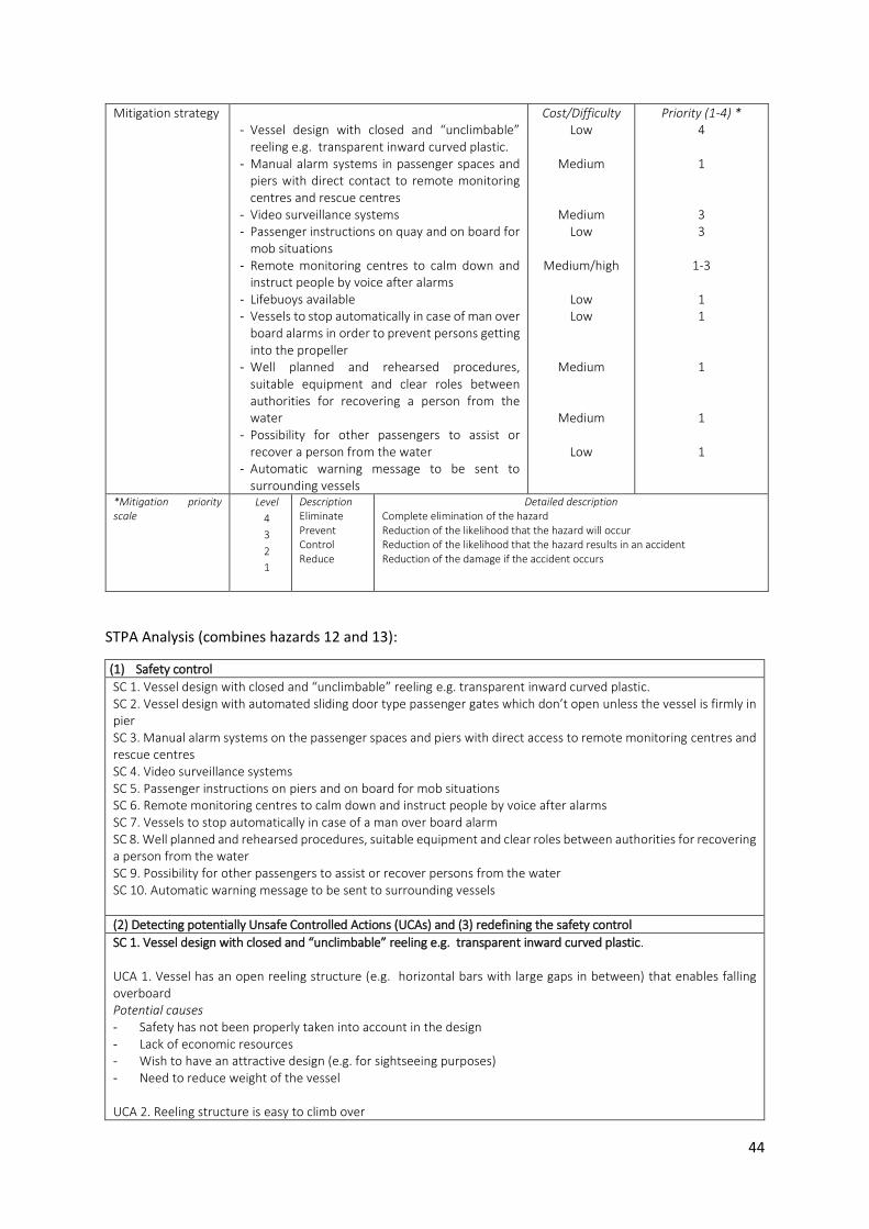
44
Mitigation strategy - Vessel design with closed and “unclimbable”
reeling e.g. transparent inward curved plastic. - Manual alarm systems in passenger spaces and
piers with direct contact to remote monitoring centres and rescue centres
- Video surveillance systems - Passenger instructions on quay and on board for
mob situations - Remote monitoring centres to calm down and
instruct people by voice after alarms - Lifebuoys available - Vessels to stop automatically in case of man over
board alarms in order to prevent persons getting into the propeller
- Well planned and rehearsed procedures, suitable equipment and clear roles between authorities for recovering a person from the water
- Possibility for other passengers to assist or recover a person from the water
- Automatic warning message to be sent to surrounding vessels
Cost/Difficulty Low
Medium
Medium Low
Medium/high
Low Low
Medium
Medium
Low
Priority (1-4) * 4
1
3 3
1-3
1 1
1
1
1
*Mitigation priority scale
Level
4
3
2
1
Description Eliminate Prevent Control Reduce
Detailed description Complete elimination of the hazard Reduction of the likelihood that the hazard will occur Reduction of the likelihood that the hazard results in an accident Reduction of the damage if the accident occurs
STPA Analysis (combines hazards 12 and 13):
(1) Safety control
SC 1. Vessel design with closed and “unclimbable” reeling e.g. transparent inward curved plastic. SC 2. Vessel design with automated sliding door type passenger gates which don’t open unless the vessel is firmly in pier SC 3. Manual alarm systems on the passenger spaces and piers with direct access to remote monitoring centres and rescue centres SC 4. Video surveillance systems SC 5. Passenger instructions on piers and on board for mob situations SC 6. Remote monitoring centres to calm down and instruct people by voice after alarms SC 7. Vessels to stop automatically in case of a man over board alarm SC 8. Well planned and rehearsed procedures, suitable equipment and clear roles between authorities for recovering a person from the water SC 9. Possibility for other passengers to assist or recover persons from the water SC 10. Automatic warning message to be sent to surrounding vessels
(2) Detecting potentially Unsafe Controlled Actions (UCAs) and (3) redefining the safety control
SC 1. Vessel design with closed and “unclimbable” reeling e.g. transparent inward curved plastic. UCA 1. Vessel has an open reeling structure (e.g. horizontal bars with large gaps in between) that enables falling overboard Potential causes - Safety has not been properly taken into account in the design - Lack of economic resources - Wish to have an attractive design (e.g. for sightseeing purposes) - Need to reduce weight of the vessel UCA 2. Reeling structure is easy to climb over

45
Potential causes - Safety has not been properly taken into account in the design - Lack of economic resources - Easy way to get on board or off board in case of emergency Redefining of the safety control Vessel design with closed and “unclimbable” reeling e.g. transparent inward curved plastic: - The best way to prevent man over board situations is to design vessels impossible or at least very difficult to
jump or fall overboard from - Emergencies have to be taken into account already in the initial design phase
SC 2. Vessel design with automated sliding door type passenger gates which don’t open unless the vessel is firmly moored UCA 1. Vessel design with open ends like in cable ferries enables passengers to fall or jump overboard. Potential causes - Safety has not been properly taken into account in design - Lack of economic resources - Easy way to get on-board or off-board in case of emergency UCA 2. If doors open at the wrong time, passengers may fall or jump over board Potential causes - Sensor malfunction - Intentional damaging of the door Redefining of the safety control Vessel design with automated sliding door type passenger gates which don’t open unless the vessel is firmly in pier: - Well-designed door structure with pressure sensors etc. is an effective way to control the movement of
passengers and prevent man over board situations - Passenger safety in case of door malfunction has to be taken into account
SC 3. Manual alarm systems in the passenger spaces and piers with direct contact to remote monitoring centres UCA 1. Passengers on board have no easy and quick way to send alarm about man over board situation Potential causes - Poor planning of vessels’ safety features - Lack of economic resources UCA 2. Alarm systems are not connected directly to remote monitoring centres; information about the situation is not forwarded Potential causes - Poor planning of vessels’ safety features - Lack of economic resources Redefining of the safety control Manual alarm systems in the passenger spaces and piers with direct access to remote monitoring centres and rescue centres: - It is essential to get the information about mob situations immediately to the rescuers when someone falls or
jumps into the water. Delays in this information endangers the whole rescue operation
SC 4. Video surveillance systems UCA 1. Man over board situations are not noticed, because there are no video surveillance systems for monitoring passenger safety on board Potential causes - Poor planning of vessels’ safety features - Lack of economic resources UCA 2. Video material from vessels is not monitored continuously, automatically or manually Potential causes - Lack of economic resources - Lack of commitment

46
UCA 3. Video material is not streamed ashore from vessels in real time Potential causes - Technical problem - Lack of redundancy - Lack of economic resources UCA 4. There is no reaction to situations captured in the video surveillance system Potential causes - Lack of commitment - Work overload - Lack of training and/or instructions - Human machine interface limitations UCA 5. Without active video surveillance the preventive factor cannot be achieved Potential causes - Lack of economic resources UCA 6. Video surveillance does not perform properly Potential causes - Bad planning - Problems in data transfer - Technical problems with the camera - Lack of redundancy - Lack of economic resources - Power source malfunction - Quality of the picture affected by weather conditions - Different lighting conditions have not been taken into consideration Redefining of the safety control Video surveillance system: - If a person travels alone or falls over board without other passengers noticing, the situation can only be detected
by technical means - Reliable real-time data transfer ashore is an essential part of the system if a human does the monitoring - Existence of video surveillance can prevent erratic behaviour. With active monitoring, persons can also interfere
with the situations - Technical specifications of the system should be planned and implemented efficiently - The video surveillance system itself has to be monitored continuously
SC 5. Passenger instructions on quay and on board for man over board situation UCA 1. Passenger instructions are poor or not easy enough to understand Potential causes - Poor planning UCA 2. Passengers do not familiarize themselves with the instructions Potential causes - Positioning of the instructions - Visual look of the instructions - Language barrier - Time constraint - Wrong means for providing instructions Redefining of the safety control Passenger instructions on piers and on board for man over board situations: - Other passengers on board are the best available resource in an emergency, if they know what to do
- Good passenger information is clear, simple and does not leave place for misunderstandings
- If the information is visually interesting and the means for giving it are correct, people are more likely to read,
listen or watch it.
SC 6. Remote monitoring centres to calm down and instruct people by voice after alarms

47
UCA 1. People on board panic, don’t know what to do or act irrationally, because the system for instructing people by voice does not exist Potential causes - Poor planning of vessels’ safety features - Lack of economic resources UCA 2. Connection between vessels and the monitoring centres does not work Potential causes - Technical problems - Lack of redundancy UCA 3. The way of giving the instructions is not suitable and they are not followed on board Potential causes - Poor planning - Psychological factors have not been considered deeply enough when planning the messages - Persons in charge of the situation have not been properly trained Redefining of the safety control Remote monitoring centres to calm down and instruct people by voice after alarms: - Calming of the passengers is necessary in order to keep them functional and prevent irrational actions that
make the situation worse. With detailed instructions, untrained people are able to perform operations they would not be able to do on their own
- Persons giving instructions have to be well trained in the LSA functions as well as in crowd and crisis management
- Connections between vessel and shore have to be reliable and there have to be redundancies
SC 7. Vessel to stop automatically in case of man over board alarm UCA 1. The vessel is not programmed to stop in case of a mob alarm and person in the water gets into the moving vessel’s propeller Potential causes - Poor planning of vessels’ safety features UCA 2. Persons cannot be found again and/or the passengers are not able to assist because the vessel has continued on her route Potential causes - Poor planning of vessels’ safety features Redefining of the safety control Vessels to stop automatically in case of man over board alarms: - Stopping the vessel without delay after an alarm protects the person in the water and ensures that he/she can
get all available help
- The propeller of the vessel should be properly covered if the engines are running at the man over board scene
SC 8. Well planned and rehearsed procedures, suitable equipment and clear roles between authorities for recovering a person from the water UCA 1. Assistance for recovering a person from the water takes too long to arrive Potential causes - Information about the situation has not been received or is not correct - Boats or personnel are not available close enough - It is unclear who should respond to the situation Redefining of the safety control Well planned and rehearsed procedures, suitable equipment and clear roles between authorities for recovering a person from the water: - In man over board situations there is no time for planning, only for well-rehearsed action
- Man over board situations may happen in areas where there is no help available close by. Co-operation between
authorities increases the amount of available resources and speed up rescuing
SC 9. Possibility for other passengers or the vessel to assist or recover a person from the water

48
UCA 1. Vessel’s hull and structure is designed so “safe” that the passengers on board cannot assist or recover anyone from the water Potential causes - High reeling without any “emergency exits”
UCA 2. The LSA equipment available are too complicated to be used by untrained people Potential causes - Lack of suitable equipment in the market- Poor planning of vessels’ safety features- Lack of economic resources
UCA 3. Without automatic LSA equipment operated by the vessel, the person in the water may not get help Potential causes - Lack of suitable equipment in the market- Poor planning of vessels’ safety features- Lack of economic resources
Redefining of the safety control Possibility for other passengers or the vessel to assist or recover a person from the water: - Autonomous vessels should be designed to protect people and keep them inside. However, there must be
emergency exits and devices that can be used to pull a person on board from the water
- All LSA-equipment on board should be easily available, simple, safe and easy to use for untrained persons- Automatic LSA equipment such as lifebuoys, ladders, slides, ramps, or emergency lighting should be
automatically activated by the vessel
SC 10. Automatic warning message to be sent to surrounding vessels
UCA 1. An autonomous vessel does not inform the surrounding vessels about the mob situation and therefore they cannot assist. Potential causes - Poor planning of vessels’ safety features- Lack of suitable means to inform other vessels
UCA 2. Autonomous vessel does not inform the surrounding vessels about the mob situation and another vessel runs over the person in the water Potential causes - Poor planning of vessel’s safety features- Lack of suitable means to inform other vessels
Redefining of the safety control An automatic warning message to be sent to surrounding vessels: - Other vessels in the area are most likely the fastest available assistance, but only if they know the situation- Without information about the mob situation, they are an imminent danger to the person in the water
Hazard 14. Persons getting injured Hazard H14. Persons getting injured
Hazard effect/ description
Provide extra details regarding the designated severity rating Persons being injured may lead to medical emergencies on board or on piers. The hazard can have negative impact on people. It can result in injuries or loss of human life.
Causal factors Describe the hazard as system state. What conditions could influence the effect of the hazard occurrence? - Slipping, tripping or falling- Violence by other passengers- Automatic doors with malfunction in the sensors
Mitigation strategy - Good lighting and air conditioning
Cost/Difficulty Low
Priority (1-4) * 3

49
- Unobstructed access and non-slippery floor materials in piers and the vessel
- Manual alarm systems in the passenger spaces and on piers with direct contact to remote monitoring centres
- Vessels re-route to the closest medical evacuation pier and transmit their position to the authorities.
- Video surveillance systems - Passenger instructions on piers and on board for
medical emergencies - Remote monitoring centres to calm down and
instruct people by voice after alarms - Well planned and rehearsed procedures for
medical evacuation - Possibility for other passengers to give first aid to
injured persons
Low
Medium
Medium
Medium Low
Medium
Low
Low
4
1
1
3 1
1
1
1
*Mitigation priority scale Level
4
3
2
1
Description Eliminate Prevent Control Reduce
Detailed description Complete elimination of the hazard Reduction of the likelihood that the hazard will occur Reduction of the likelihood that the hazard results in an accident Reduction of the damage if the accident occurs
Hazard 15. Person(s) medical condition Hazard H15. Person(s) medical condition
Hazard effect/ description
Provide extra details regarding the designated severity rating If a passenger gets sick or has a seizure it may lead to a medical emergency on board or on a pier. The hazard can have negative impact on people. It can result in injuries or loss of human life.
Causal factors Describe the hazard as system state. What conditions could influence the effect of the hazard occurrence? - Movement of the vessel - Heat - Allergic reactions - Passengers not having necessary personal medication with them
Mitigation strategy - Good lighting and air conditioning - Unobstructed access and non-slippery floor
materials in piers and vessels - Manual alarm systems in passenger spaces and
piers with direct contact to remote monitoring centres
- Vessels re-route to the closest medical evacuation pier and transmit their position to the authorities
- Video surveillance systems - Passenger instructions on piers and on board for
medical emergencies - Remote monitoring centre to calm down and
instruct people by voice after the alarm - Well planned and rehearsed procedure for
medical evacuation - Possibility for other passengers to give first aid to
an injured person
Cost/Difficulty Low Low
Medium
Medium
Medium
Low
Medium
Low
Low
Priority (1-4) * 3 4
1
1
3 1
1
1
1

50
*Mitigation priority scale Level
4
3
2
1
Description Eliminate Prevent Control Reduce
Detailed description Complete elimination of the hazard Reduction of the likelihood that the hazard will occur Reduction of the likelihood that the hazard results in an accident Reduction of the damage if the accident occurs
STPA Analysis (combines hazards 14 and 15):
(1) Safety control
SC 1. Good lighting and air conditioning SC 2. Unobstructed access and non-slippery floor materials in piers and the vessel SC 3. Manual alarm systems in the passenger spaces and on piers with direct contact to remote monitoring centre and rescue centre SC 4. Vessels re-route to the closest medical evacuation pier and transmit their position to the authorities SC 5. Video surveillance systems SC 6. Passenger instructions on piers and on board for medical emergencies SC 7. Remote monitoring centres to calm down and instruct people by voice after the alarm SC 8. Well planned and rehearsed procedures for medical evacuation SC 9. Possibility for other passengers to give first aid to injured persons
(2) Detecting potentially Unsafe Controlled Actions (UCAs) and (3) redefining the safety control
SC 1 Good lighting and air conditioning UCA 1. Person cannot see obstructions and accidentally falls Potential causes - Poor planning of light source locations and luminosity - Obstructions create shadows - Blackout UCA 2. High temperatures can trigger seizures or medical conditions Potential causes - Vessel design - Blackout - Inadequate AC system - Power saving Redefining of the safety control Good lighting and air conditioning: - Good lighting ensures that passengers can move safely - With proper temperature on board, passengers remain calm and alert, and it reduces the risk of seizures and
medical conditions
SC 2 Unobstructed access and non-slippery floor materials in piers and vessels UCA 1. The entrance to vessels is not level Potential causes - Pier and vessel entrances are not on the same level - Steps UCA 1. Vessel or pier floors are covered with slippery coating and a passenger falls Potential causes - poor planning - Water, snow or ice on the floor - Spill or litter Redefining of the safety control Unobstructed access and non-slippery floor materials in piers and vessels - Unobstructed access and non-slippery floor material in piers and vessels ensure that passengers can move safely
in all weather conditions
SC 3 Manual alarm systems in passenger spaces and piers with direct contact to remote monitoring centres

51
UCA 1. Passengers on board have no easy and quick way to send alarms in case of medical emergencies Potential causes - Poor planning of vessels’ safety features - Lack of economic resources - UCA 2. Alarm systems are not connected directly to the remote monitoring centres the information about the situation is not forwarded Potential causes - Poor planning of vessels’ safety features - Lack of economic resources Redefining of the safety control Manual alarm systems on the passenger spaces and piers with direct access to remote monitoring centre: - It is essential to get the information about the medical emergency immediately to the authorities. Delay in this
information endangers the safety of the patient
SC 4 Vessels re-route to the closest medical evacuation pier and transmit their position to the authorities UCA 1. If vessels continue to the next planned pier there might arise a delay for patients to get the medical attention needed Potential causes - Poor planning and testing - There is no alarm or information about the situation - Software error UCA 2. The information about the emergency pier does not reach the authorities or it is incorrect Potential causes - Poor planning and testing - Conflicting information from different sources Redefining of the safety control Vessels re-route to the closest medical evacuation pier and transmit their position to the authorities: - The patient safety has to be prioritized and medical attention reached as soon as possible - Special attention should be payed to the information flow and the planning of emergency harbours
SC 5. Video surveillance systems UCA 1. A medical emergency is not noticed, because there is no video surveillance system to monitor passenger safety on board Potential causes - Poor planning of vessel’s safety features - Lack of economic resources
UCA 2. Video material from the vessel is not monitored continuously, automatically or manually Potential causes - Lack of economic resources - Lack of commitment - UCA 3. Video material is not transferred ashore from the vessel in real time. Potential causes - Technical problem - Lack of redundancy - Lack of economic resources UCA 4. There is no reaction to situations captured in the video surveillance systems Potential causes - Lack of commitment - Work overload - Lack of training and/or instructions - Human machine interface limitations

52
UCA 5. Video surveillance does not perform properly Potential causes - Bad planning - Problems in data transfer - Technical problems with the camera - Lack of redundancy - Lack of economic resources - Power source malfunction - Quality of the picture affected by weather conditions - Different lighting conditions are not taken into consideration Redefining of the safety control Video surveillance system: - If a person travels alone, situations can only be detected by technical means - Reliable real-time data transfer ashore is an essential part of the system if a human does monitoring - Technical specifications of the system should be planned and implemented efficiently
- The video surveillance system itself has to be monitored continuously
SC 6. Passenger instructions for medical emergencies on piers and on board UCA 1. Passenger instructions are poor or not easy enough to understand Potential causes - Poor planning UCA 2. Passengers do not familiarize themselves with the instructions Potential causes - Positioning of the instructions - Visual look of the instructions - Language barrier - Time constraint - Wrong means for providing instructions Redefining of the safety control Passenger instructions on piers and on board for medical emergencies: - Other passengers on board are the best available resource in an emergency, if they know what to do
- Good passenger information is clear, simple and does not leave place for misunderstandings
- If the information is visually interesting and the means for giving it is suitable, people are more likely to read,
listen or watch it.
SC 7 Remote monitoring centres to calm down and instruct people by voice after alarms UCA 1. People on board panic, don’t know what to do or act irrationally, because the system for instructing people by voice does not exist Potential causes - Poor planning of vessels’ safety features - Lack of economic resources UCA 2. Connection between vessels and the monitoring centres does not work Potential causes - Technical problem - Lack of redundancy UCA 3. The way of giving instructions is not suitable and they are not followed on board Potential causes - Poor planning - Psychological factors have not been considered deeply enough in planning the messages - Persons in charge of the situation has not been properly trained Redefining of the safety control Remote monitoring centres to calm down and instruct people by voice after alarms:

53
- Calming of passengers if necessary in order to keep them functional and prevent irrational actions that make the situation worse. With detailed instructions, untrained people are able to perform operations they would not be able to do on their own
- Persons giving instructions have to be well trained in the medical first aid as well as in crowd and crisis management
- Connections between vessels and shore have to be reliable and include redundancies
SC 8 Well planned and rehearsed procedures for medical evacuation UCA 1. Medical assistance takes too long to arrive Potential causes - Information about situations is not received or is not correct - Boats or personnel are not available close enough - It is unclear who should respond to the situation Redefining of the safety control Well planned and rehearsed procedures for medical evacuation: - In medical emergencies, there is no time for planning, only for well-rehearsed action
- Medical emergencies may happen in areas where there is no help available close by. Co-operation between
authorities increases the amount of available resources and speed up the process
SC 9 Possibility for other passengers to give first aid to injured persons UCA 1. There is no first aid equipment Potential causes - Poor planning - Lack of economic resources - They have been stolen - They have not been replaced after having been used UCA 2. First aid equipment available are too complicated to be used by untrained people Potential causes - Poor planning - Lack of economic resources - Instructions are missing or bad Redefining of the safety control Possibility for other passengers to give first aid to injured persons: - First aid equipment on board should be easily available, simple, safe and easy to use for untrained persons - First aid equipment should be placed so that they cannot be easily tampered, e.g. inside cabinets with alarms if
opened.

54
4.2.3 The representation of the initial safety management strategy for ferry A and B: step
five
The initial safety management strategy for ferries A and B consists of 73 safety controls, which have
different approaches for mitigating the 15 defined hazards and for preventing and responding to the
10 defined accidents.
Table 2 below presents the safety controls, their control logic principles and the risk they aim to
mitigate. The safety controls are grouped by the hazard. The safety control types are categorized with
colours: orange (controls that attempt to eliminate the hazard), yellow (controls for reducing the
likelihood that the hazard will occur), green (controls for reducing the likelihood that the hazard results
in an accident), and blue (controls for reducing the damage if the accident occurs).
Table 2. Safety controls, control logic principles and the risks mitigated, grouped by the hazards
Hazard 1. Object detection sensor error
Safety Control (SC) Control logic principle Risks mitigated 1. Sensor system redundancy and diversity
If one sensor fails the redundancy ensures there is another sensor functioning. The equipment chosen to provide the redundancy has to be correct in order to provide the user with the required information at all times
> Lack of information due to error in a single sensor > Undetected sensor failure > External or common cause failure affecting all equipment simultaneously
1. UPS (Uninterrupted Power Source)
If there is a disturbance in the vessel power system the UPS can temporarily provide power for the critical equipment. When the UPS setup is planned, installed and maintained properly, the user can count on a reliable backup system
> Disturbances in vessels’ power systems affect vessels’ object detection sensors’ operation > The UPS does not work or takes too long to switch on > The capacity of the UPS is not sufficient to provide power for the equipment
2. Appropriate heating, cooling and cleaning systems
By applying sensors with proper heating and/or cooling systems it can be ensured that they function properly in all operating conditions. Proper automatic cleaning systems ensure the appropriate function of the sensors outdoors
> Equipment is not able to function properly in winter conditions > Equipment is not able to function properly due to high temperatures > Equipment lens is dirty > Condensation inside equipment
3.Thorough commissioning of equipment set
When the equipment set is thoroughly tested and certified (preferably by an independent body) it ensures that the equipment function properly, are compatible and the operation can be run safely.
> The equipment set has not been properly tested or not tested at all before operation
4. Appropriate and continuous on board maintenance programs
By implementing an on board maintenance program it can be ensured that all critical systems remain functional at all times. A well planned maintenance program covers all necessary areas on board and it is adjusted separately for each vessel. Maintenance done timely and according to the program by competent personnel ensures the smooth operation of the sensors.
> There is no on board maintenance program > The maintenance program does not cover the necessary elements and the life cycle of the hardware > The maintenance program is not followed or the maintenance is not done properly
5. Continuous system diagnosis and proof testing
Ensures that the system functions as it should. Test design should be planned carefully and updated after changes in the system in order to cover all the necessary functions and recognize problems. Possible effect on the operation should be taken into account in the planning.
> There is no continuous system diagnosis and proof testing > The continuous system diagnosis and proof testing do not cover all necessary functions > The test is not able to recognize problems
1. Autonomous integrity monitoring
A Well designed and up to date integrity monitoring system ensures that the data has not been damaged or manipulated
> There is no integrity monitoring > Integrity monitoring gives wrong information
Hazard 2. Artificial Intelligence (AI) failure
Safety Control (SC) Control logic principle Risks mitigated

55
2. Thorough planning, testing and commissioning of AI Software
Thorough planning, testing and commissioning of AI software ensure that the software is robust and free of errors. Applicable standards should be followed.
> Thorough planning, testing and commissioning of AI are not done > Insufficient planning, testing and commissioning of AI
6. Computer and software redundancy
Computer and software redundancy ensure the availability of the AI functions at all times
> Computer breaks down and there is not computer and software redundancy > Secondary computer does not take over in case of a failure
1. UPS (Uninterrupted Power Source)
If there is a disturbance in the vessel power system, the UPS can temporarily provide power for the critical equipment. When the UPS setup is planned, installed and maintained properly, the user can count on a reliable backup system
> Disturbances in vessels’ power systems affect vessels’ AI systems’ operation > The UPS does not work or takes too long to switch on > The capacity of the UPS is not sufficient to provide power for the AI system as long as needed or the capacity in terms of power and/or energy of the UPS is exceeded
7. Appropriate cooling for computers
In order to function properly all computer components must be kept within permissible operating temperature limits. Cooling systems should be selected carefully. Both the waste heat produced by the computer components and possible external heat sources should be taken in to account.
> Computer does not function reliably due to overheating.
4. Appropriate and continuous on board maintenance programs
By implementing a maintenance program it can be ensured that all critical systems remain functional at all times. A well-planned maintenance program covers all necessary areas on board and it is adjusted separately for each vessel. Maintenance done timely and according to the program by competent personnel ensures smooth operation. Special attention should be paid not only to properly timed software updates but also to the updating process.
> There is no on board maintenance program > The maintenance program does not cover the necessary elements and the life cycle of the hardware > The maintenance program is not followed or the maintenance is not done properly > Software updates are not done and the system is not capable to correct detected issues > Software updates create inappropriate functions in the system > Software and hardware do not match
3. Robust system design Robust system design should be able to isolate failures in the system and to let the rest of the system operate.
> Poor and/or missing data are not detected and coped with > Single point failures takes the whole system down
8. Appropriate system (software) design and maintenance processes
Ensure that the system meets customer expectations. Requires good communication between customers, sales people and developers, but also good documentation. Special attention should be paid to reviews throughout the process and software verification at the end. Change management must not be forgotten.
> User requirements are not known or taken into account and the final product is not the expected > System requirements are not clear for the developers and do not cover relevant issues > System design and system implementation do not meet expectations > Software is not verified properly > Change management is not working properly
3. Technical fault (e.g. mechanical failure)
Safety Control (SC) Control logic principle Risks mitigated 4. Redundancy of critical systems
With redundancy in the systems the effect of the single failure can be minimized. Redundancy and system integration should be taken into account already in the planning stage. Proper testing and commissioning of the system verifies that all critical systems have been identified. Changes in the system should be managed with a proper protocol/ process.
> Single failures can cause vessel operation to stop > Critical equipment has not been identified correctly > Critical systems have been changed without proper analysis of the effects on the system
5. Thorough planning, testing and commissioning of all technical systems
The process should be done in good cooperation between the designer, buyer, builder, suppliers and regulators. The autonomous status of the vessel should be taken into account through the process. New and efficient practices for commissioning and testing autonomous vessel systems should be developed in cooperation with the relevant stakeholders.
> Autonomous operations have not been taken into account in the whole system design > Tests fail to recognize problems or potential faults in the systems > The commissioning is not done thoroughly
9. Planned and predictive maintenance programs
With proper maintenance programs the safety of
the vessel can be ensured, the number of
technical faults minimized and the life cycle of technical systems maximized. Maintenance programs have to take into account system interactions.
> The system fails due to the lack of maintenance > The maintenance done is not of the right type or it is done poorly > Maintenance programs fail to take into account interaction between systems

56
10. Distance monitoring and fault detection of technical systems
Safe and effective operation of autonomous vessels require distance monitoring and failure detection. Remote monitoring increases the reliability of the operation and minimizes off-hire periods. Without proper monitoring of the data quality, distance monitoring and fault detection systems cannot produce reliable information.
> Vessel faults are not detected > Distance monitoring and fault detection of technical systems do not work
4. Heavy weather/sea conditions + 5. Strong currents
Safety Control (SC) Control logic principle Risks mitigated 6. Correctly set and followed operational limits
Permanent operational limits set by shipping companies and agreed between all the parties involved, ensure that operations are stopped before the safety of the vessel is compromised. Vessels’ features, capability to manoeuvre and operating areas should be considered when setting the operational limits. When the limits and automatic procedures for situations when the limits are crossed are programmed in vessel systems, they are followed without the need to make decision case by case. Thus they are not exposed to human error. Sending an alarm to remote monitoring centres, when limits are crossed, acts as a double check in order to ensure that the vessel is able to cease her operations safely.
> Shipping companies have not set operational limits for the vessel. > Operational limits set by shipping companies are too high for safe operation of vessels > Operational limits set for vessels are not followed.
11. Weather routing and constant weather and sea state monitoring
Checking weather forecasts should always be part of route planning. Checking forecasts automatically against the plan (also in the permanent routes between two points) every time before departure ensures vessel safety. Constant automatic monitoring of weather forecasts as well as local real-time weather data during the trip, ensure the safety along the whole way. Receiving weather forecasts from more than one source gives redundancy and allows comparison. With pre-planned alternative routes programmed to the system, vessels can automatically be re-routed safely when necessary. Re-routing functions should always be properly tested in the commission stage.
> Environmental conditions are not taken into account when planning vessel routes > Weather and sea state are not constantly monitored when vessels are in operation > Vessel’s route is not changed accordingly when environmental conditions require doing so.
12. Vessels equipped with adequate environmental sensors for local conditions
With proper equipment on board (or along the route), vessels are able to react also to sudden local changes in the conditions. Already when planning vessels, winter conditions and other local needs, equipment characteristics required in the area as well as redundancy needs should be considered carefully.
> Vessels are not equipped with adequate and appropriate sensors in order to monitor local conditions > There is not enough redundancy in environmental sensors
2. Keeping vessels steady against the wind and waves, heading to an emergency harbour or anchoring
If an unexpected weather change makes continuing on the route unsafe, automatic route specific contingency actions (such as driving with minimum manoeuvring speed against the wind etc. or re-routing vessels to a suitable emergency harbour) programmed to the system are necessary precautions.
> In case that the weather/sea conditions change suddenly over the operational limits, vessels continue on their routes normally instead of choosing a safer option for the situation.
3. Knowledge of local currents and other local environmental conditions
Available information about local currents and frequent weather conditions is a valuable tool when planning vessels and their routes. Especially in archipelagos, lakes and rivers there can be strong local currents, places where fog regularly forms or where the wave height rises above normal..
> Information about local currents and local environmental conditions in rivers and archipelagos has not been gathered > Information about local currents and local environmental conditions has not been taken into account when planning vessel routes
4. Constant monitoring of currents and adjusting the steering accordingly
Vessels reliably equipped to monitor affecting real time currents, automatically adjusting steering accordingly, without delay, are able to manoeuvre and dock safely and smoothly.
> There is no equipment available to monitor the current in real time > Current monitoring systems do not function correctly > Current monitoring information is not connected to the AI and steering equipment > Too long delays in the steering system to react to drifting.

57
5. Constant monitoring and predictions of vessels’ capability
With constant monitoring and prediction of vessels’ capability, vessels are able to adjust operational limits and operation in general when necessary. There might be external or internal factors that require lowering the operational limits temporarily.
> Vessel capability is not monitored > Information of vessel capability is not used to adjust the operational limits or operation.
6. Position reference equipment failure
Safety Control (SC) Control logic principle Risks mitigated 7. Equipment (sensor) redundancy
If one sensor fails, redundancy ensures there is another sensor functioning. System design must include adequate diagnosing functions in order to recognize sensor failures and perform the switch over procedure when necessary. Equipment used to provide redundancy should be completely independent from one another to reduce the risk of a common cause failure taking it down at the same time
> Lack of information due to error in a single sensor > Sensor failures are not detected due to lack of information from other equipment to be compared with > External or common cause failures take several equipment down at the same time
6. Combinations of different types of local and satellite position reference systems
Combination of local and satellite position reference systems provide reliable position information in different conditions and locations, and help to detect possible errors in the information
> Positioning is based on satellite positioning only and vessel e.g. loses her position in case of a satellite system failure or poor satellite availability > Satellite positioning reference equipment gives incorrect information and there is no local positioning information to compare it with > Positioning is based on local position reference systems only and vessels e.g. lose position due to poor weather conditions
13. Satellite positioning equipment with jamming detection and/or anti-jamming function
Jamming detection ensures that jamming is noticed and users can switch to local position reference systems. An anti-jamming function reduces the risk of losing position or receiving wrong/inaccurate position information due to GPS jamming.
> Vessels lose position due to jamming > Vessels receive wrong or inaccurate position information due to jamming
1. UPS (Uninterrupted Power Source)
If there is a disturbance in the vessel power system, UPSs can temporarily provide power for critical equipment. When UPS setup is planned, installed and maintained properly, the user can count on reliable backup systems. For GPS systems a UPS with a quick switch on function is critical. In case of power loss GPS equipment need to reacquire the position fix which may take several minutes at worst case
> Disturbances in vessels’ power systems affect operation of vessels’ position reference equipment > The UPS does not work > The UPS takes too long to switch on and the GPS equipment needs to reacquire the position fix > The capacity of the UPS is not sufficient to provide power for the equipment as long as needed or the capacity in terms of power and/or energy of the UPS is exceeded
14. Appropriate heating, cooling and cleaning systems
By applying sensors with proper heating and/or cooling systems it can be ensured that they function properly in all operating conditions. Applying sensors with automatic cleaning systems ensure that they function properly outdoors
> Equipment is not able to function properly in winter conditions > Equipment is not able to function properly due to high temperature s > Equipment lenses are dirty > Condensation inside equipment
15. Thorough installation and commissioning of equipment set
Placing of GPS antennas has to be optimal with regards to sky view and distance to transmitting radio equipment. Installations of the GPS antennas and cabling have to be thoroughly planned and performed by certified suppliers. An unobstructed sensor head and antenna view is essential when using local position reference systems. When the equipment set is thoroughly tested and certified (preferably by an independent body) it ensures that the equipment functions properly, are compatible and the operation can be run safely.
> GPS antennas have limited sky view > GPS antennas are placed too close to radio equipment causing interference > GPS antennas’ cable length and amplification are not optimized > Local position reference systems’ sensor head or antenna view is blocked by obstacles > The equipment set has not been properly tested or not tested at all before operation.
16. Appropriate and continuous on board maintenance programs
By implementing on board maintenance programs it can be ensured that all critical systems remain functional at all times. A well-planned maintenance program covers all necessary areas on board and it is adjusted separately for each vessel. Maintenance done timely and accordingly to the program by competent personnel ensures smooth operation of the sensors
> There is no on board maintenance program > The maintenance program does not cover the necessary elements and the life cycle of the hardware > The maintenance program is not followed or the maintenance is not done properly.

58
17. Continuous system diagnosis and proof testing
Continuous system diagnosis and regular proof testing ensure that the system functions, as it should. Test design should be planned carefully and updated after changes in the system in order to cover all necessary functions and recognize potential problems. Possible effects on the operation caused by the tests should be taken into account in the planning
> There is no continuous system diagnosis and proof testing > The continuous system diagnosis and proof testing do not cover all necessary functions > The test is not able to recognize problems
1. Autonomous Integrity monitoring
Well designed and up to date integrity monitoring systems ensure that the data has not been damaged or manipulated
> There is no integrity monitoring > Integrity monitoring gives wrong information > Integrity monitoring is not able to recognize spoofing signals
7. Overloading of vessels
Safety Control (SC) Control logic principle Risks mitigated 8. Automated passenger gates which do not allow more than maximum number of passengers on board
With reliable passenger count, overloading of vessels and exceeding of maximum number of passengers can be avoided. The systems have to take into account that people stay on-board, people travel without tickets, wheelchairs, and families with children, bikes, baby strollers etc. who can not board vessels though passenger gates. Gates should not separate parents and children. Possible solutions for counting reliably could be e.g. automatic software and camera systems that compare passengers going in and out, defining a boarding processes and boarding areas on the pier, or emptying the vessel completely before reloading.
> There is no system to count the number of passengers on-board > Passenger count system is not reliable > The passenger gates separate family members (parents and children)
9. Clear rules, weighing and monitoring of the cargo taken on board
By monitoring the vessel’s trim, list and draft the weight of the vessel can be calculated. Possible solutions for calculating the weight are e.g. pressure sensors, echo sounders and visual readings of draft.
> Vessels are overloaded because there is no knowledge of weight of cargo on-board > Cargo weighing systems are not reliable
10. In case of adding permanent weights on board, stability calculations and tests to be redone.
If stability calculations are not up to date the vessel operation may not be safe and according to regulations.
>The added weights are not recorded >The recorded weights are inaccurate > The stability tests/calculations are not updated
11. Automatic continuous monitoring of vessels’ stability (draft, trim, list and GM), and the vessel is programmed not to leave the pier if over the limits.
There should always be real-time information available about vessel stability in order to operate safely. By programming the safety limits allowed into the system, leaving a pier can be prevented in unsafe stability situations. With redundant monitoring systems, unnecessary stops in operation or unsafe situations caused by an equipment malfunction can be minimized
> There is no system to monitor vessel stability > Vessel does not leave pier even though the vessel is loaded correctly > The vessel leaves the pier overloaded > There is only one monitoring system with no redundancy
8. Shifting of weights
Safety Control (SC) Control logic principle Risks mitigated 18. Passenger instructions on quay and on board
Good passenger information is clear, simple and doesn’t leave place for misunderstandings. If the information is visually interesting and the means for providing it are correct, people are more likely to read, listen to or watch it.
> Passenger instructions regarding weight distribution are poor or not easy enough to understand > Passengers do not familiarize themselves with the instructions
19. Design of vessel With good ship design, passenger and cargo movements and stability can be controlled. For example seating arrangements can be used as natural dividers and the vessel can be designed with a very high initial stability.
>The design does not prevent people from crowding or falling to one side of vessels > Vessels lists considerably in case of crowding of people on one side > Cargo and storage spaces do not have any compartments that would prevent items from shifting to one side of the vessel
12. Firefighting systems that use very little water or no water at all
When selecting firefighting systems to be installed on-board, stability and free surface effect caused by the firefighting water should be taken into account.
> The use of large amounts of firefighting water creates free surfaces and may endanger vessel stability.
13. Anti-heeling system Anti-healing systems compensate for small heels and increases the comfort and safety of the passengers. However, a possible malfunction of
> Listing of vessels cannot be corrected and it causes danger or discomfort for the passengers. > Malfunctioning of the anti-heeling system may endanger the safety of the vessel

59
the system must not be able to endanger the safety of the vessel.
7. Remote monitoring centres monitor vessel stability and instruct people by voice if necessary
Calming of passengers is necessary in order to keep them functional and prevent irrational actions that make situations worse. With detailed instructions, untrained people are able to perform operations they would not be able to do on their own. Persons giving instructions have to be well trained in basic ship stability as well as crowd and crisis management. Connections between vessel and shore have to be reliable and there have to be redundancies.
> People on board panic, don’t know what to do or act irrationally, because there is no system for instructing people > Connections between vessel and monitoring centres do not work > The way of giving instructions is not suitable and they are not followed onboard
9. Flooding
Safety Control (SC) Control logic principle Risks mitigated 14. Double hull and compartments
A double hull and a compartmented structure help autonomous vessels to maintain stability in case of accidents.
> Single hull allows large amounts of water to flood the spaces under the waterline very quickly if penetrated. > Vessels lose stability due to the water moving freely inside the hull
15. Well planned and built piping system
Using double wall pipes and correct materials for pipes and connection points, depending on the systems, make the piping systems resistant and less likely to break. Good planning, building, testing, and oversight of the whole process make piping systems reliable, easy to use and maintain.
> Bursting of a single wall pipe allows the water (or other liquids) to leak to the spaces inside the hull. > Rigid metal piping breaks easier due to vibrations or pressure shocks than other types of piping. > Complex piping systems with many connection points are more likely to break and leak > There are only system drawings and no production drawings and construction workers have to make decisions about the details
8. Automatic monitoring systems for tanks, pipes, bilges, and cofferdams
Leaks and bursts in hull and piping can be detected quickly by automatic monitoring systems. In case of accidents, vessel stability can also be evaluated and possible actions planned accordingly. However, the function of the monitoring systems needs to be monitored itself.
> If an autonomous vessel, without an automatic monitoring system for tanks, bilges and cofferdams has an accident, vessel stability problems and possible leaks cannot be detected. > A burst pipe in the engine room is not noticed
20. Firefighting systems that use very little water or no water at all
Reduce the possibility that firefighting water causes stability problems to vessels and therefore allows systems to be used as long as necessary. May damage vessel equipment less compared to a situation when large amounts of water are used in firefighting. One good option could be to use aerosol systems (potassium based) for fire extinguishing and water mist systems for cooling
> Vessels lose stability due to large amounts of water used in firefighting > Firefighting water damages vessel equipment
21. Good drainage systems on deck
Remove water from the deck efficiently and reduce possible stability problems. Winter conditions have to be taken into account when planning drainage systems.
> Rainwater and sea spray flood the deck and weaken vessel stability due to the lack of efficient drainage systems > The drainage system is blocked by dirt or debris, or by ice in winter conditions
9. Effective bilge pumps Keep the vessel afloat if there is water in the engine room and gives time for evacuating passengers. They protect vessel equipment and systems in case of flooding. Pump redundancy and emergency power systems have to be taken into account
> Bilge pumps are not effective enough to pump out the water coming in from a penetration in the hull > Bilge pumps break and there is no redundancy > Bilge pumps are not connected to the emergency power system
10. Ignition of electrical equipment and wiring
Safety Control (SC) Control logic principle Risks mitigated 22. Thorough planning and commissioning of electrical equipment and wiring
Thorough planning and commissioning of electrical equipment and wiring ensure that the components, wiring and equipment chosen are the correct ones for the actual use of the vessel and the installation and penetrations are done properly. The testing of the electrical equipment and wiring, detects the possible faults in the system
> Wrong equipment and wiring or their installation cause fires or cause fires to spread more rapidly than normally > Information used in the planning stage does not correlate with the use of the system > Testing is poorly planned and done
23. Appropriate cooling and heating for electrical systems
By providing appropriate cooling and heating for electrical systems, the overheating and problems caused by humidity can be prevented
> Overheating of the equipment breaks the equipment or causes a fire > Condensation causes a short circuit in electrical equipment

60
24. Preventive maintenance programs
Preventive maintenance programs are the best way to prevent ignition of electrical equipment and wiring. By checking the cleanliness, connections and proper function of the protection equipment regularly, the risk of ignition of electrical equipment and wiring can be reduced
> Dust in the equipment may result in overheating and ignition > Loose connections may result in overheating and ignition > Malfunction of the circuit breakers or other protection components e.g. arc protection system
16. Circuit breakers and fault current protection
Circuit breakers and fault current protection protect equipment and prevent the risk of ignition of the electrical equipment and wiring
> Circuit breakers do not open or cut off the power
1. Automatic fire extinguishing systems inside electrical cabinets
Automatic fire extinguishing systems inside electrical cabinets prevent spreading of fire to the surrounding spaces and reduce damage to equipment. Attention should be paid to defining the capacity of the extinguishing system.
> Without extinguishing systems inside cabinets, fires can spread to surrounding spaces > Capacity of the extinguishing system is too small to extinguish the fire > Too large capacity of the aerosol or gas extinguishing system builds up pressure and increases the fire instead of extinguishing it.
2. Automatic fire detection, alarm and extinguishing systems in engine spaces
Automatic and effective fire detection and alarm systems provide ship systems and remote operation centres information about the situation without delay. Detector locations, types and number of detectors should be planned carefully. Automatic extinguishing systems are the quickest and safest way to extinguish engine room fires in autonomous vessels. Firefighters may not be able to enter the engine spaces physically at all. Attention should be paid to choosing the right type of extinguishing systems and defining the right capacity for the space.
> Fire in engine spaces cannot be detected > Alarm systems are not connected directly to the remote monitoring centres; the information about the situation is not forwarded > Fire fighters may not be able to enter or extinguish the fire in the engine room > Extinguishing systems are not capable to extinguish the fire
11. Passengers starting a fire
Safety Control (SC) Control logic principle Risks mitigated 10. Smoke detectors and automatic fire extinguishing systems in passenger spaces
Smoke detectors are the most suitable devices to detect fires in passenger spaces. However, the use of flame detectors additionally could also be considered. It is essential to get the information about fires immediately. Delays in this information endanger the whole rescue operation. When choosing extinguishing systems for passenger spaces the safety of the passenger should be priority number one. For example, low pressure water mist systems with concealed nozzles is a safe and reliable option in an unmanned vessel
> Fire in passenger spaces is not detected > Extinguishing systems are not capable to extinguish the fire
25. No smoking signs on piers and vessels
No smoking signs inform the passengers that smoking on board is not allowed. Smoking is one of the most likely reasons for having fires in passenger spaces
> Passengers smoke on-board and starts a fire
11. Video surveillance systems
Existence of video surveillance can prevent erratic behaviour. With active monitoring dangerous situations can also be identified in real-time and intervened. Reliable real-time data transfer ashore is an essential part of the system, if a human does the monitoring. Appropriate technical specifications of systems should be planned and implemented efficiently. Video surveillance systems have to be efficiently monitored.
> Without active video surveillance the preventive factor cannot be achieved > Video material is not transferred ashore from the vessel in real time. > There is no reaction to situations captured by the video surveillance system > Video surveillance does not perform properly
12. Both automatic and manual fire alarm systems in passenger spaces with direct access to remote monitoring centres
It is essential to get information about fires immediately to remote monitoring centres. Delays in this information endanger the whole rescue operation. In some cases, passengers may notice fires earlier than automatic systems and need to be able to send alarms manually. Passengers need to be informed about activated alarms
> Passengers on board have no easy and quick way to send an alarm about fires in passenger spaces > Smoke detectors are activated but there is no alarm for passengers > Alarm systems are not connected directly to the remote monitoring centres, the information about the situation is not forwarded

61
26. Use of inflammable and fire resistant materials in passenger spaces
The material used in passenger spaces has significant effect on passenger safety in case of fires. The amount of plastic should be kept low
> Flammable and non-fire resistant materials allow the fire to spread quickly
3. Possibility for the passengers to extinguish fires
Firefighting equipment on board should be easily available, simple, safe and easy to use for untrained persons. The equipment should be placed so that it cannot be easily tampered with, e.g. inside a cabinet with an alarm if opened
> Firefighting equipment available are too complicated to be used for untrained people > Firefighting equipment are not properly located, missing or not ready for use.
12. Unintended falling over board + 13. Intended jumping over board
Safety Control (SC) Control logic principle Risks mitigated 17. Vessel design with closed and “unclimbable” reeling e.g. transparent inward curved plastic.
The best way to prevent mob situations is to design vessels from the beginning so that it is impossible or at least very difficult to jump or fall overboard from them. Emergency situations have to be taken into account already in the initial design phase.
> Vessels have an open reeling structure (e.g. horizontal bars with large gaps in between) that allow for falling overboard.> The reeling structure is easy to climb over
18. Vessel design with automated sliding door type passenger gates which don’t open unless the vessel is firmly ,moored
Well-designed door structures with pressure sensors etc. is an effective way to control the movement of passengers and prevent man over board situations. Passenger safety in case of door malfunction has to be taken into account.
> Vessel design with open ends like in cable ferries allows for passengers to fall/jump overboard> If the doors open at the wrong time, passengers mayfall or jump over board
4. Manual alarm systems in passenger spaces and piers with direct contact to remote monitoring centres
It is essential to get the information about man over board situations immediately to the rescuers when someone falls or jumps into the water. Delays in this information endanger the whole rescue operation.
> Passengers on board have no easy and quick way to send alarms about man over board situations > Alarm systems are not connected directly to the remote monitoring centres, the information about the situation is not forwarded
27. Video surveillance systems
If a person travels alone or falls over board without other passengers noticing, the situation can only be detected by technical means. Reliable real-time data transfer ashore is an essential part of the system if monitoring is done by a human. Existence of video surveillance can prevent erratic behaviour. With active monitoring a person can also interfere with situations. Appropriate technical specifications of the systems should be planned and implemented efficiently. The video surveillance systems have to be monitored continuously
> Man over board situations are not noticed, because there is no video surveillance system to monitor passenger safety onboard > Video material from vessels is not monitored continuously automatically or manually > Video material is not transferred ashore from vessels in real time > There is no reaction to situations captured by video surveillance systems> Without active video surveillance the preventive factor cannot be achieved > Video surveillance does not perform properly
28. Passenger instructions on piers and on board for man over board situation
Other passengers on board are the best available resource in emergency situations, if they know what to do. Good passenger information is clear, simple and doesn’t leave place for misunderstandings. If the information is visually interesting and the means for providing it are correct, people are more likely to read, listen to or watch it.
> Passenger instructions are poor or not easy enough to understand> Passengers do not familiarize themselves with the instructions
5. Remote monitoring centre to calm down and instruct people by voice after the alarm
Calming passengers if necessary in order to keep them functional and prevent irrational actions that make the situation worse. With detailed instructions, untrained people are able to perform operations they would not be able to do on their own. Persons giving instructions have to be well trained in LSA functions as well as in crowd and crisis management. Connections between vessels and shore have to be reliable and there have to be redundancies.
> People on board panic, don’t know what to do or act irrationally, because there is no system for instructing people by voice > Connections between vessels and monitoring centresdo not work > The way of giving instructions is not suitable and theyare not followed onboard
6. Vessels to stop automatically in case of man over board alarms
Stopping vessels without delay after an alarm protects persons in the water and ensures that they can get all available help. The propeller of the vessels should be properly covered if the engines are running at the man over board scene
> Vessels are not programmed to stop in case of mob alarms and persons in the water get into the moving vessel’s propeller > Persons cannot be found in the water and/or passengers are not able to assist because the vessel has continued on her route.

62
7. Well planned and rehearsed procedures, suitable equipment and clear roles between authorities for recovering persons from the water
In man over board situations there is no time for planning, only for well-rehearsed action. Man over board situations may happen in areas where help is not close by. Co-operation between authorities increases the amount of available resources and speeds up the rescuing.
> Assistance for recovering persons from the water takes too long to arrive.
8. Possibility for other passengers or the vessel to assist or recover a person in the water
Even if vessels are designed to protect people and keep them inside, there must be emergency exits and devices that can be used to pull a person on board from the water. All LSA-equipment on board should be easily available, simple, safe and easy to use for an untrained person. Automatic LSA equipment such as lifebuoys, ladders, slides, ramps, or emergency lighting should be automatically activated.
> Vessels’ hull and structure are designed so “safe” that the passengers on board cannot assist or rescue anyone from the water > LSA equipment available are too complicated to be used by untrained people > Without automatic LSA equipment operated by the vessel, persons in the water may not get help
9. Automatic warning messages to be sent to surrounding vessels
Other vessels in the area are most likely the fastest available assistance, but only if they know the situation. Without information about the situation, they are an imminent danger to persons in the water.
> Autonomous vessels do not inform surrounding vessels about man over board situations and therefore other vessels cannot assist. > Autonomous vessels do not inform surrounding vessels about the man over board situation and another vessel runs over the person in the water
14. Persons getting injured + 15. Medical conditions
Safety Control (SC) Control logic principle Risks mitigated 29. Good lighting and air conditioning
Good lighting ensures that passengers can move safely. With proper temperature on board, passengers remain calm and alert, and it reduces the risk of seizures and medical conditions
> Persons cannot see an obstruction and fall accidentally > High temperatures can trigger seizures or medical conditions
19. Unobstructed access and non-slippery floor materials in piers and vessels
Unobstructed access and non-slippery floor materials in piers and vessels ensure that passengers can move safely in all weather conditions
> Entrance to vessels is not level > Vessel or pier floors are made with slippery coating and passengers fall
4. Manual alarm systems in the passenger spaces and piers with direct contact to remote monitoring centres
It is essential to get the information about medical emergencies immediately to the authorities. Delays in this information endanger the safety of the patient
> Passengers on board have no easy and quick way to send alarms about medical emergencies > Alarm systems are not connected directly to remote monitoring centres, information about the situation is not forwarded
10. Vessels re-route to closest medical evacuation pier and transmits position to the authorities
Patient safety has to be prioritized and medical attention reached as soon as possible. Special attention should be paid to the information flow and the planning of the emergency harbours.
> Vessels continue to next planned pier and there is a delay for the patient to get the medical attention needed. > The information about the emergency does not reach the authorities or it is incorrect
27. Video surveillance systems
If persons travel alone, situations can only be detected by technical means. Reliable real-time data transfer ashore is an essential part of the system if a human does the monitoring. Technical specifications of systems should be planned and implemented efficiently. Video surveillance systems have to be monitored continuously.
> Medical emergencies are not noticed, because there is no video surveillance system to monitor passenger safety on board > Video material from vessels is not monitored continuously automatically or manually > Video material is not transferred ashore from vessels in real time > There is no reaction to situations captured by video surveillance systems > Video surveillance does not perform properly
11. Passenger instructions on quay and on board for medical emergencies
Other passengers on board are the best available resource in emergencies, if they know what to do. Good passenger information is clear, simple and does not leave place for misunderstandings. If the information is visually interesting and the means for providing it are correct, people are more likely to read, listen to or watch it.
> Passenger instructions are poor or not easy enough to understand > Passengers do not familiarize themselves with the instructions
5. Remote monitoring centres to calm down and instruct people by voice after alarms
Calming of passengers if necessary in order to keep them functional and prevent irrational actions that make situations worse. With detailed instructions, untrained people are able to perform operations they would not be able to do on their own. Persons giving instructions have to be well trained in medical first aid as well as in crowd and crisis management. Connections between vessel and shore have to be reliable and there have to be redundancies.
> People on board panic, don’t know what to do or act irrationally, because the system for instructing people by voice does not exist > Connections between vessels and monitoring centres do not work > The way of giving instructions is not suitable and the instructions are not followed on board

63
12. Well planned and rehearsed procedure for medical evacuation
In medical emergencies, there is no time for planning, only for well-rehearsed action. Medical emergencies may happen in areas where help is not close by. Co-operation between authorities increases the amount of available resources and speed up the process.
> Medical assistance takes too long to arrive
13. Possibility for other passengers to give first aid to injured persons
First aid equipment on board should be easily available, simple, safe and easy to use for untrained persons. First aid equipment should be placed so that it cannot be easily tampered with, e.g. inside cabinets with alarms if opened
> There is no first aid equipment available > First aid equipment available is too complicated to be used for untrained people.
Figure 1 below presents the types of safety controls utilized for the prevention and response to the
defined accidents shown on the top of the table. The types of safety controls are marked with the
same color codes as in Table 2. Each coded square represents a single safety control and the codes
H1-H14 show which hazard these controls are connected to in each accident. By connecting the hazard
number and the safety control number on the left-hand side column, details of the safety control in
question can be found in Table 2.
Figure 1. Safety control types utilized for prevention and response to defined accidents
Distribution of the safety control types based on the mitigation approach in the initial safety
management strategy for ferry A and B is presented in table 3. 27 % of the controls focus on
implementing actions, which attempt to eliminate the hazard. 18 % of the safety controls focus on
implementing actions to reduce the likelihood that the hazard will result in an accident. 18 % of the
controls focus on implementing actions to reduce the damage if the accident occurs.
Safety Control(SC)
1 H1 H1 H1 H1 H1 H1 H1 H1 H1 H1 H1 H1 H1 H1 H102 H2 H1 H4 H2 H1 H2 H1 H2 H1 H4 H2 H4 H2 H4 H103 H2 H1 H4 H2 H1 H2 H1 H2 H1 H4 H2 H4 H2 H4 H114 H3 H1 H4 H3 H1 H3 H1 H3 H1 H4 H3 H4 H3 H4 H12 H12 H125 H3 H1 H4 H3 H1 H3 H1 H3 H1 H4 H3 H4 H3 H4 H12 H12 H126 H4 H2 H4 H2 H2 H4 H2 H4 H4 H2 H4 H4 H2 H4 H127 H6 H2 H2 H2 H6 H2 H4 H2 H4 H2 H8 H128 H2 H2 H2 H2 H2 H2 H7 H9 H129 H3 H3 H3 H3 H3 H3 H7 H9 H1210 H3 H3 H3 H3 H3 H3 H7 H11 H14 H1411 H4 H4 H4 H4 H7 H11 H14 H1412 H4 H4 H4 H4 H8 H11 H14 H1413 H6 H6 H6 H6 H8 H14 H1414 H6 H6 H6 H6 H915 H6 H6 H6 H6 H916 H6 H6 H6 H6 H1017 H6 H6 H6 H6 H1218 H8 H1219 H8 H14 H1420 H921 H922 H1023 H1024 H1025 H1126 H1127 H12 H14 H1428 H12
29 H12 H14 H14
Total SC 24 15 12 10 9 930 16 16 30 24
Accident9 101 2,1 2,2 3 4 5 6 7 8
SC control strategy:
Attempt to eliminate the hazardReduce the likelihood that the hazard will occurReduce the likelihood that the hazard results in an accidentReduce the damage if the accident occur

64
Table 3. Distribution of the safety control types used
Safety control mitigation approach Safety controls defined
Attempt to completely eliminate the hazard 19
Attempt to reduce the likelihood that the hazard will occur 29
Attempt to reduce the likelihood that the hazard results in an accident
12
Attempt to reduce the damage if the accident occurs 13

65
5. Conclusions
This report presents a systematic hazard analysis prior to the concept design phase of an autonomous
vessel. The process consists of five different steps to elaborate a systematic analysis of hazards and to
define safety controls for mitigating and preventing the identified hazards. These safety controls are
the basis of the initial safety management strategy of autonomous vessels and their operational
system.
The process is suitable for analysing hazards and proposing safety controls with a systematic approach
that covers the operational context of autonomous vessels. The process was applied to analyse two
concepts of autonomous ferries operating in urban waterways in Finland. As an outcome of the
process, ten accidents were defined and fifteen hazards identified. The result of the analysis is an
initial safety management strategy composed of 73 safety controls. The controls provide itemized
information that is relevant for planning, designing and constructing autonomous vessels and their
entire operational system.
The process application promotes an anticipated involvement of different key stakeholders for
planning the management of safety for autonomous vessels and their operational system. The
implementation of the process produces initial itemized information, which can guide the initial design
process of autonomous vessels and their entire operational system. The aim is to initiate the design
of safety in the earliest conceptual design phase for engineering more efficient and safer autonomous
ferries and systems.
Acknowledgements
This report is part of the research project “Smart City Ferries” (ÄLYVESI). The project was funded by the European Regional Development Fund (ERDF). Additional financiers were the Finnish Transport Safety Agency and the cities of Helsinki and Espoo. Cooperators in the project are Novia University of Applied Sciences, Turku University of Applied Sciences, Aalto University and City of Turku. More information about the project can be found in http://www.aboamare.fi/About-ÄlyVESI. This paper and analysis are part of the project task 2.2. The Safety of an Unmanned and Automated Ferry. The authors want to thank all the experts who participated in the workshops and shared their knowledge in the analysis carried out in this study.

66
References
Chatzimichailidou, M., and Dokas, I. 2015. “The Risk Situation Awareness Provision Capability and Its
Degradation in the Überlingen Accident over Time.” Procedia Engineering 128 (January):44–53.
Chen, J., Zhang, S., Lu, Y. and Tang P. 2015. “STPA-Based Hazard Analysis of a Complex UAV System in
Take-Off.” In 2015 International Conference on Transportation Information and Safety (ICTIS), 774–
79.
Fleming, C., Spencer M., Thomas, J., Leveson, N. and Wilkinson, C. 2013. “Safety Assurance in NextGen
and Complex Transportation Systems.” Safety Science 55 (June):173–87
Hinchman, J., Clark, M., Hoffman, J., Hullbert, B., Snyder, C. 2012. Towards safety assurance of trusted
autonomy in air force flight critical systems. In Computer Security Applications Conference, Layered
Assurance Workshop
Jalonen, R., Tuominen, R. and Wahlström, M. 2017. Safety of Unmanned Ships - Safe Shipping with
Autonomous and Remote Controlled Ships. Aalto University.
https://aaltodoc.aalto.fi:443/handle/123456789/28061.
Leveson, N. 2011. Engineering a Safer World: Systems Thinking Applied to Safety. MIT Press.
Leveson, N., Dulac, N., Marais, K. and Carroll, J. 2009. “Moving Beyond Normal Accidents and High
Reliability Organizations: A Systems Approach to Safety in Complex Systems.” Organization Studies 30
(2–3):227–49
Oscarsson, J., Stolz-Sundnes, M., Mohan, N. and Izosimov, V. 2016. “Applying Systems-Theoretic
Process Analysis in the Context of Cooperative Driving.” In 2016 11th IEEE Symposium on Industrial
Embedded Systems (SIES), 1–5
Rødseth, O.J., and Burmeister, H.C. 2015. “Risk Assessment for an Unmanned Merchant Ship.”
TransNav, International Journal on Marine Navigation and Safety Od Sea Transportation 9
(3).http://www.transnav.eu/Article_Risk_Assessment_for_an_Unmanned_Rødseth,35,593.html
Teivainen A. 2017. Rolls-Royce to set up R&D centre in Turku, Finland. Helsinki Times. March 2017
Valdez Banda, O.A and Goerlandt, F. 2017. A STAMP-based approach for designing maritime safety
management systems. Submitted to Safety Science. December 2016
Vermesan, O. and Friess, P. 2013. Internet of Things: Converging Technologies for Smart Environments
and Integrated Ecosystems. River Publish

67
Appendix 1
The background and expertise areas for each participating expert
A: Master mariner and master of marine technology with over 14 years of seagoing experience as
marine officer, and about 5 years of experience from maritime administration as senior inspector and
marine safety investigator.
B: Senior researcher with about 4 years of practical experience in quality and safety management of
maritime traffic and port logistics, and over 5 years of experience in the research of safety and risk
management practices implemented in the maritime industry.
C: Shipbuilding engineer with over 14 years of experience in ship design and technical management
in the maritime industry and about six years of experience from classification societies.
D: Design and production engineer with over six years of experience as project manager and director
in smart mobility and transport automation projects.
E: Sea captain with ten years of seagoing experience as marine officer and shipmaster, and 20 years
of experience in the maritime simulator training and simulator environment development in a
maritime college.
F: Doctor of technology, specialized in control engineering, automation and system identification. The
expert has over six years of experience in the marine electric and automation industry and is currently
a manager of intelligent shipping in one of the leading technology companies in the field.
G: Doctor of philosophy specialized in positioning technologies. The expert has over ten years of
experience in the development of GNNS products and over four years of experience in researching
geodesy, geoinformatics, navigation, remote sensing and spatial data infrastructure.
H: Software engineer with over ten years of experience as designer of software and algorithms for
automation and energy domains. Specialized in critical and high-reliability systems.
I: Naval architect with 14 years of experience in ship design and construction, and works currently as
managing director of a shipyard. The expert also has over 9 years of technical ship management
experience from a shipping company.
J: Coast guard officer with a total of 28 years of experience of maritime search and rescue work, of
which seven years as a search and rescue mission coordinator.
K: Fire engineer with about ten years of rescue service experience specialized in fire inspections and
contingency planning in chemical sites and ports. Currently the expert works as leading fire inspector
in charge of developing control activities for the South West Finland rescue area.
L: Ship owner with over 20 years of experience in ship management and practical ship operations, and
12 years of experience as ferry captain in the Finnish archipelago. The expert also acts as safety
manager (DPA) of a shipping company.
M: City risk manager with a master’s degree in engineering. This expert is in charge of the safety and
security strategies and their implementation in one the largest cities of Finland.
68
N: Master mariner with five years of seagoing experience as marine officer and 11 years of experience
as survival instructor in a maritime safety training centre. The expert also has experience in
development and evaluation of marine lifesaving equipment.
O: Master mariner with three years of seagoing experience as marine officer and 10 years of
experience as simulator instructor and training manager in a maritime college.
P: Master mariner with five years of experience in developing maritime on-board solutions. The expert
currently works as CEO of a company focusing on maritime IT/ICT/IoT/telematics and safety systems.
Q: Naval architect with over five years of experience in the implementation of maritime safety
regulations for ship design and construction. The expert also has over 3 years of experience in
researching the interaction between sea ice and ship structures.
R: Chief engineer with 18 years of seagoing experience as marine engineer. The expert is also the
safety manager (DPA) in a shipping company specialized in operating public transportation routes in a
city area.

Yrkeshögskolan Novia har ca 3500 studerande och personalstyrkan uppgår till ca 390 personer. Novia är den största svenskspråkiga yrkeshögskolan i Finland som har
examensinriktad ungdoms‐ och vuxenutbildning, utbildning som leder till högre yrkeshögskoleexamen samt fortbildning och
specialiseringsutbildning. Novia har utbildningsverksamhet i Vasa, Jakobstad, Raseborg och Åbo.
Yrkeshögskolan Novia är en internationell yrkeshögskola, via samarbetsavtal utomlands och internationalisering på hemmaplan. Novias styrka ligger i närvaron och nätverket i hela Svenskfinland.
Novia representerar med sitt breda utbildningsutbud de flesta samhällssektorer. Det är få organisationer som kan uppvisa en
sådan kompetensmässig och geografisk täckning. Högklassiga och moderna utbildningsprogram ger studerande en bra plattform för
sina framtida yrkeskarriärer.
Yrkeshögskolan Novia Wolffskavägen 33, 65100 Vasa, Finland
Tfn +358 (0)6 328 5000 (växel), www.novia.fi
Ansökningsbyrån PB 6, 65201 Vasa, Finland Tfn +358 (0)6 328 5555
Yrkeshögskolan Novia upprätthåller en publikations‐ och produktionsserie för att sprida information och kunskap om verksamheten såväl regionalt, nationellt som internationellt.
Publikations‐ och produktionsserien är indelad i fem kategorier:
R ‐ Rapporter • P ‐ Produktioner • A ‐ Artiklar • L ‐ Läromedel • S ‐ Studerandes arbete
Läs våra senaste publikationer på www.novia.fi/FoU/publikation‐och‐produktion
ISSN 1799‐4179ISBN 978‐952‐7048‐47‐4 (online)


![Experimental analysis of submerged flapping foils ... · principles of flapping foil wave propulsion [1,2,3,4]. MOST (Autonomous Vessels) Ltd have developed a long range endurance](https://img.pdfslide.net/doc/110x75/5f061c6a7e708231d4165844/experimental-analysis-of-submerged-iapping-foils-principles-of-iapping-foil.jpg)