Embed Size (px)
Citation preview


RAPID RISK ANALYSIS STUDY OF
PROPOSED RESIDUE UPGRADATION
PROJECT AT MATHURA, UTTAR PRADESH
Doc No.: A257-000-04-41-RRA-1001
Rev. No: 0
Page 2 of 45
Template No. 5-0000-0001-T2 Rev. 1 Copyrights EIL ¬ All rights reserved
PREFACE
Engineers India Limited (EIL), New Delhi, has been entrusted by M/s IOCL to carry out the EIA and
Rapid Risk Analysis of the facilities (New and Revamp) coming under Residue Up-Gradation and
Distillate yield Improvement Project with 11 MMTPA Crude Processing at Mathura Refinery. As a part
of the project RRA is being carried out for the subject job.
Rapid Risk Analysis study identifies the hazards associated with the project, analyses the
consequences, of all likely incidents, draws suitable conclusions and provides necessary
recommendations to mitigate the hazard/ risk.
This Rapid Risk Analysis study is based on the information made available at the time of this study and
EIL’s own data source for similar plants. EIL has exercised all reasonable skill, care and diligence in
carrying out the study. However, this report is not deemed to be any undertaking, warrantee or
certificate.

RAPID RISK ANALYSIS STUDY OF
PROPOSED RESIDUE UPGRADATION
PROJECT AT MATHURA, UTTAR PRADESH
Doc No.: A257-000-04-41-RRA-1001
Rev. No: 0
Page 3 of 45
Template No. 5-0000-0001-T2 Rev. 1 Copyrights EIL ¬ All rights reserved
TABLE OF CONTENTS
SECTION-1 ................................................................................................................................................................. 6
EXECUTIVE SUMMARY .......................................................................................................................................... 6
1.1 PROJECT DESCRIPTION ....................................................................................................... 6
1.2 CONCLUSIONS AND RECOMMENDATION .......................................................................... 6
SECTION-2 ............................................................................................................................................................... 12
INTRODUCTION ..................................................................................................................................................... 12
2.1 STUDY AIMS AND OBJECTIVE ........................................................................................... 12
2.2 SCOPE OF WORK ................................................................................................................ 12
2.3 PROCESS DESCRIPTION .................................................................................................... 13
2.3.1 RESID HYDROCRACKER UNIT (REHU) .............................................................................. 13
2.3.2 OTHERS UNIT ....................................................................................................................... 14
SECTION-3 ............................................................................................................................................................... 15
SITE CONDITION ................................................................................................................................................... 15
3.1 GENERAL ............................................................................................................................. 15
3.2 SITE, LOCATION AND VICINITY .......................................................................................... 15
METEOROLOGICAL CONDITIONS ...................................................................................... 15
SECTION-4 ............................................................................................................................................................... 18
HAZARDS ASSOCIATED WITH THE PROJECT ............................................................................................... 18
4.1 GENERAL ............................................................................................................................. 18
4.2 HAZARDS ASSOCIATED WITH FLAMAMBLE MATERIALS .............................................. 18
4.2.1 HYDROGEN .......................................................................................................................... 18
4.2.2 NAPHTHA AND OTHER HEAVIER HYDROCARBONS ....................................................... 18
4.3 HAZARDS ASSOCIATED WITH TOXIC/CARCINOGENIC MATERIALS ............................. 19
4.3.1 HYDROGEN SULPHIDE ....................................................................................................... 19
4.3.2 CHLORINE ............................................................................................................................ 19
SECTION-5 ............................................................................................................................................................... 21
HAZARD IDENTIFICATION ................................................................................................................................. 21
5.1 GENERAL ............................................................................................................................. 21

RAPID RISK ANALYSIS STUDY OF
PROPOSED RESIDUE UPGRADATION
PROJECT AT MATHURA, UTTAR PRADESH
Doc No.: A257-000-04-41-RRA-1001
Rev. No: 0
Page 4 of 45
Template No. 5-0000-0001-T2 Rev. 1 Copyrights EIL ¬ All rights reserved
5.2 MODES OF FAILURE ........................................................................................................... 21
5.3 SELECTED FAILURE CASES .............................................................................................. 22
SECTION-6 ............................................................................................................................................................... 24
CONSEQUENCE ANALYSIS ................................................................................................................................. 24
6.1 GENERAL ............................................................................................................................. 24
6.2 CONSEQUENCE ANALYSIS MODELLING .......................................................................... 24
6.2.1 DISCHARGE RATE ............................................................................................................... 24
6.2.2 DISPERSION ......................................................................................................................... 24
6.2.3 FLASH FIRE .......................................................................................................................... 24
6.2.4 JET FIRE ............................................................................................................................... 25
6.2.5 POOL FIRE ........................................................................................................................... 25
6.2.6 VAPOR CLOUD EXPLOSION ............................................................................................... 25
6.2.7 TOXIC RELEASE .................................................................................................................. 25
6.3 SIZE AND DURATION OF RELEASE ................................................................................... 25
6.4 DAMAGE CRITERIA ............................................................................................................. 26
6.4.1 LFL OR FLASH FIRE ............................................................................................................ 26
6.4.2 THERMAL HAZARD DUE TO POOL FIRE, JET FIRE AND FIRE BALL .............................. 26
6.4.3 VAPOR CLOUD EXPLOSION ............................................................................................... 26
6.4.4 TOXIC HAZARD .................................................................................................................... 27
6.5 CONSEQUENCE ANALYSIS OF THE SELECTED FAILURE CASES ................................. 27
6.5.1 NEW PROPOSED UNITS ...................................................................................................... 27
6.5.1.1 NAPHTHA SPLITTER UNIT (NSU) ....................................................................................... 27
6.5.1.2 VACUUM DISTILLATION UNIT (VDU) .................................................................................. 28
6.5.1.3 HYDROGEN GENERATION UNIT (HGU) ............................................................................. 28
6.5.1.4 SULPHUR RECOVERY UNIT (SRU) ..................................................................................... 29
6.5.1.5 ONCE THROUGH HYDROCRACKER (OHCU) .................................................................... 29
6.5.1.6 RESID HYDROCRACKING UNIT .......................................................................................... 30
6.5.1.7 OFFSITES ............................................................................................................................. 31
6.5.1.8 COOLING TOWER (CT) ........................................................................................................ 31
RAPID RISK ANALYSIS STUDY OF
PROPOSED RESIDUE UPGRADATION
PROJECT AT MATHURA, UTTAR PRADESH
Doc No.: A257-000-04-41-RRA-1001
Rev. No: 0
Page 5 of 45
Template No. 5-0000-0001-T2 Rev. 1 Copyrights EIL ¬ All rights reserved
6.5.2 REVAMPED UNITS ............................................................................................................... 31
6.5.2.1 CRUDE DISTILLATION UNIT (CDU) .................................................................................... 31
6.5.2.2 DIESEL HYDROTREATING UNIT (DHDT) ............................................................................ 32
SECTION-7 ............................................................................................................................................................... 34
7.1 LIST OF LAST MAJOR REFINERY INCIDENTS GLOBALLY IN LAST 10 YEARS ............. 34
7.1.1 FIRE AND EXPLOSION AT CHEVRON RICHMOND REFINERY, USA ............................... 34
7.1.2 FIRE AND EXPLOSION AT AMUAY REFINERY, VENEZUELA........................................... 34
7.1.3 TERMINAL FIRE AND EXPLOSION AT JAIPUR (INDIA) .................................................... 34
7.1.4 BUNCEFIELD TANK FARM FIRE AND EXPLOSION, UK .................................................... 34
7.1.5 EXPLOSION AND FIRE AT FORMOSA PLASTICS, ILLINOIS, USA ................................... 35
7.1.6 EXPLOSION AND FIRE AT BP TEXAS REFINERY, USA .................................................... 35
SECTION-8 ............................................................................................................................................................... 36
CONCLUSIONS AND RECOMMENDATIONS .................................................................................................... 36
GLOSSARY ............................................................................................................................................................... 43
REFERENCES ......................................................................................................................................................... 45
ANNEXURE-I: CONSEQUENCE ANALYSIS HAZARD DISTANCES
ANNEXURE-II: FIGURES FOR CONSEQUENCE ANALYSIS
ANNEXURE-III: OVER ALL PLOT PLAN

RAPID RISK ANALYSIS STUDY OF
PROPOSED RESIDUE UPGRADATION
PROJECT AT MATHURA, UTTAR PRADESH
Doc No.: A257-000-04-41-RRA-1001
Rev. No: 0
Page 6 of 45
Template No. 5-0000-0001-T2 Rev. 1 Copyrights EIL ¬ All rights reserved
SECTION-1
EXECUTIVE SUMMARY
1.1 PROJECT DESCRIPTION
Engineers India Limited (EIL), New Delhi, has been entrusted by M/s IOCL to carry out the EIA and
Rapid Risk Analysis of the facilities (New and Revamp) coming under Residue Up-gradation and
Distillate Yield Improvement Project with 11.0 MMTPA Crude Processing at Mathura Refinery. As a part
of the project RRA is being carried out for the subject job.
This report contains observations, results and recommendations of Rapid Risk analysis study of New
and Revamp Units considered under proposed residue Upgradation project. The study evaluates
consequences from the different potential accident scenarios considered for the units and associated
off-site facilities. Subsequently, analyses the extent of damage due to such incidents and draws suitable
mitigating measures.
1.2 CONCLUSIONS AND RECOMMENDATION
The major conclusions and recommendations arising out of the Rapid Risk analysis study for the IOCL
Mathura Refinery are summarized below. This is based on the detail analysis given in Sections – 6.
NEW PROPOSED UNITS
NSU: Large Hole in Bottom line of Naphtha Splitter Ovhd. Separator: It can be observed from
consequence analysis of this failure scenario that LFL shall approach to the Refinery Compound wall on
south side and also extends into New HGU & OHCU. The Jet Fire Radiation Intensity of 37.5 & 12.5
Kw/m2 shall be affecting equipments in NSU as well as in OHCU. The 5 & 3 psi blast wave shall spread
throughout OHCU and covering majority of equipments in New HGU, moreover it shall also be crossing
Refinery Compound wall on southern side and engulfing the total truck parking & even extending
beyond it. The 12.5 & 4 Kw/m2 Radiation intensity on account of Pool Fire shall be limited to vicinity of
the unit.
As LFL shall be reaching up to the South Side Compound wall of the Refinery and 5 & 3 psi blast wave
shall be affecting Truck parking area, it is recommended to consider relocation of the Truck Parking
Area.
VDU: Vacuum Diesel Product/IR Pump Instrument Tapping Failure: From the Consequence
analysis of this failure scenario it can be observed that the LFL shall be crossing the unit’s B/L on
western side. The 37.5 & 12.5 Kw/m2 Radiation intensity on account of Jet Fire shall be extended
beyond the unit but will not be affecting any nearby unit or tankages. The 5 & 3 psi blast wave shall be
spreading throughout the unit damaging all the equipments and extending up to Tank No.: 951, 952,
953 and 954.
The affected tankage should be provided with suitable fire fighting measures. In order to prevent
secondary incident arising from this failure, it is recommended that fire monitors and hydrant provided

RAPID RISK ANALYSIS STUDY OF
PROPOSED RESIDUE UPGRADATION
PROJECT AT MATHURA, UTTAR PRADESH
Doc No.: A257-000-04-41-RRA-1001
Rev. No: 0
Page 7 of 45
Template No. 5-0000-0001-T2 Rev. 1 Copyrights EIL ¬ All rights reserved
around the tanks to be regularly checked to ensure that they are functional. Less hazardous equipments
(typically RCO pumps, hot oil system etc.) to be located on western side block of CDU.
SRU: Instrument Tapping Failure in Acid Gas K.O Drum-(TOXIC): From the consequence graph of
this failure scenario it can be observed that H2S IDLH concentration shall be extended upto existing
MSQ Unit, SRU Unit, New ETP Unit and MSQ-CR & its Substation, LPG Sphere area Operator cabin,
affecting personnel’s present in these buildings. Moreover the H2S IDLH concentration may cross the
Refinery Compound wall on western side and affecting the population beyond compound wall, if
present.
As H2S IDLH concentration shall be extended up to existing MSQ Unit, SRU Unit, any Temporary
Operator Cabin present in these units is to be removed / relocated. As MSQ-CR & its Substation are
positively pressurized, hence personnel in these building shall not be affected by H2S IDLH
concentration. Either relocation or positive pressurization of LPG Sphere area Operator cabin near LPG
MCC room is recommended. Moreover, H2S detectors are to be installed at strategic locations. DMP &
ERP should include instructions for Human evacuations from above specified areas on priority, in any
case of leakage of H2S from SRU.
OHCU: Stripper Ovhd Pump Instrument Tapping Failure: From the outcomes of consequence
analysis of this failure scenario it can be observed that LFL shall be extended up to New HGU Unit. The
37.5 & 12.5 Kw/m2 Radiation intensity on account of Jet Fire may damage the equipments in vicinity of
leakage in OHCU and also extends up to nearby New HGU. The 5 & 3 psi blast wave shall be affecting
most of equipments in OHCU, New HGU and NSU. The H2S IDLH concentration shall be affecting
DHDT/DHDS control room, proposed new control room and substation, process cooling water control
room, substation-151/11, offsite utility substation, office building, drinking & fresh water control room,
eco office and may even crosses the Boundary wall on Southern side of the Refinery affecting
individuals present.
DHDT/DHDS control room and proposed ‘new control room & substation’ are positively pressurized;
hence personnel in these building shall not be affected by H2S IDLH concentration.
It is recommended to install H2S detectors with sirens at strategic location in the plant in the event of any
such leakage to alert personnel present in the existing building viz. process cooling water control room,
drinking and fresh water control room, office building and Eco office and evacuation procedures should
be in place to evacuate personnel.
Since H2S IDLH concentration crosses boundary wall on southern side, it is also recommended to install
H2S detectors with sirens on south side of the unit and DMP should address emergency evacuation
procedures in case of any such leakage. Since the truck parking area is located in the south side
outside plant boundary hence it is recommended to consider the relocation of Truck Parking Area.

RAPID RISK ANALYSIS STUDY OF
PROPOSED RESIDUE UPGRADATION
PROJECT AT MATHURA, UTTAR PRADESH
Doc No.: A257-000-04-41-RRA-1001
Rev. No: 0
Page 8 of 45
Template No. 5-0000-0001-T2 Rev. 1 Copyrights EIL ¬ All rights reserved
OHCU: Product Fractionator Receiver Catastrophic Rupture: From the consequence graphs of this
failure scenario, it can be observed that LFL shall spreading within the unit. The 5 psi blast wave shall
be affecting all the equipments of New OHCU, NSU & HGU and even crosses the Refinery Compound
wall on southern side affecting Truck parking area. The 3 psi blast wave may further propagate and
affects equipments in H2 Plant & HGU Unit.
Though LFL shall be restricted to B/L’s of the Unit, relocation of Truck Parking Area to be looked upon
as it is getting affected by 5 and 3 psi blast wave.
OHCU: Debutanizer Receiver Catastrophic Rupture: From the incident outcome analysis of this
failure scenario, it can be observed that the Flash Fire affect zone shall be limited to vicinity of B/L’s of
unit itself. The 5 & 3 psi blast wave spreads in OHCU unit and also extends into New HGU unit. The H2S
IDLH concentration may extend beyond the unit’s B/L up to New HGU, Sub Officers Residence,
relocated Ware House & Store Shed, New CT’s, Proposed New CR for Slurry Hydrocracker & SHCU
and Existing DHDT Unit, DHDS Unit & their CR, Substation, Existing H2 Bullets, OHCU, H2 Plant, HGU,
Off Building, CT’s, Chemical House. The H2S IDLH concentration may also extends beyond the
Compound wall of Refinery on Southern side and affects population present there.
It is recommended to install H2S detectors with sirens on East & South side B/L of the unit and DMP
should address emergency evacuation procedures in case of any such scenario. The manned building
within the affect zone of H2S IDLH should be evacuated on priority.
RESID HYDROCRACKING UNIT: Fractionator Ovhd. Accumulator Catastrophic Rupture: From
the consequence analysis of this failure scenario it can be observed that LFL shall be spreading beyond
the B/L’s of the unit, extending up to New ETP, New SRU Block, New Control Room, LPG Spheres,
PRU Sphere, Mounded Bullets and may even cross the Compound wall on South side up to Marketing
Division & Truck Parking Area. The 5 & 3 psi blast wave shall be damaging all equipments in the unit &
may even spreads beyond the B/L’s of the unit covering New ETP, New Control Room, New SRU Block,
LPG Spheres, PRU Spheres, Mounded bullets, Fire Water Tank (186-T-01A/B/C), Existing HGU Unit,
Truck parking area, Marketing Division area. The 12.5 Kw/m2 Radiation intensity on account of Pool Fire
affect zone shall be limited to unit itself.
As LFL shall be reaching up to Truck Parking Area and it is also getting affected by 5 & 3 psi blast
wave, it is recommended to consider relocation / removal of Truck Parking Area.
RESID HYDROCRACKING UNIT: Naphtha Product Pump Instrument Tapping Failure: From the
incident outcome analysis of this failure scenario it can be observed that the LFL shall be spreading
throughout the unit and may approach to the New Control room. The 37.5 & 12.5 Kw/m2 Radiation
intensity on account of Jet Fire shall be limited to vicinity of units, mostly producing localized damages.
The 5 & 3 psi blast wave shall be spreading throughout the unit damaging all the equipments in the unit
and affects New Control Room, substation and marketing building.

RAPID RISK ANALYSIS STUDY OF
PROPOSED RESIDUE UPGRADATION
PROJECT AT MATHURA, UTTAR PRADESH
Doc No.: A257-000-04-41-RRA-1001
Rev. No: 0
Page 9 of 45
Template No. 5-0000-0001-T2 Rev. 1 Copyrights EIL ¬ All rights reserved
As Proposed New Control Room shall be getting affected by 5 & 3 psi blast wave, it is recommended to
be made Blast Proof with Positive Pressurization.
CT: Chlorine Toner Leakage: From the graphs of consequence analysis of this failure scenario, it can
be observed that any leakage from Chlorine Toner shall be going to affect the total area under Mathura
Refinery and even beyond the Compound walls of Refinery.
As Chlorine IDLH is affecting all the individuals inside Mathura Refinery and even beyond its Compound
wall, it is suggested to substitute / replace Chlorine with some other safer alternative viz. ClO2. In
absence of replacement it is recommended to install Cl2 detectors with sirens at strategic locations and
train people for emergency evacuation in case of Cl2 leakage. IOCL should also involve State level
authorities / District Administration in trainings/Mock drills, as Cl2 IDLH affect zone is extended beyond
the Compound Wall of Refinery, population in vicinity of the Refinery are to be informed about ill-effects
of Cl2.
REVAMPED UNITS
CDU: Large Hole in Bottom Line of Atmospheric Column Reflux Drum: From Incident Outcome
Analysis of this failure scenario, it can be observed that Flash Fire affect zone is getting extended
beyond the Unit and extending up to VBU, CRU, Portion of FCC. The 37.5 & 12.5 Kw/m2 Radiation
intensity on account of Jet Fire is spreading up to VBU, producing localized damage. The 5 psi blast
wave is damaging all of the equipments in CDU and affect zone is extended up to VBU, CRU, FCC,
Portion of MSQ, Main CR, CRU Substation, Substation-8, CT’s & Tank nos.: 951, 952, 953, 954, 955,
956. The 3 psi blast wave further propagates & affects Tank nos.: 957, 958, 404, 002 and Fire Water
Tank: 186-T-01A. The 12.5 Kw/m2 Radiation intensity on account of Pool Fire is limited to leakage
source only, mostly producing localized damage.
5 psi blast wave is affecting Main CR which is already of Blast proof construction. The affected tankage
should be provided with suitable fire fighting measures. In order to prevent secondary incident arising
from this failure, it is recommended that fire monitor and hydrant provided around the tanks to be
regularly checked to ensure that they are functional. Proper routine check to be ensured in the area to
prevent presence of any potential ignition source in the vicinity.
CDU: Naphtha Stabilizer Reflux Drum Catastrophic Rupture: From the outcomes of Consequence
Analysis of this failure scenario, it can be observed that LFL is restricted to B/L’s of the Unit. The 5 & 3
psi blast waves are spreading throughout the unit and even beyond B/L’s of the unit majorly affecting
VBU, CRU Main Control Room, CRU Substation, Substation-8 and Tanks No.: 951, 953 and 954.
Ensure the blast proof construction of CRU Main Control Room & its Substation, Substation-8.
The affected tankage should be provided with suitable fire fighting measures. In order to prevent
secondary incident arising from this failure, it is fire monitor and hydrant provided around the tanks to be
regularly checked to ensure that they are functional.

RAPID RISK ANALYSIS STUDY OF
PROPOSED RESIDUE UPGRADATION
PROJECT AT MATHURA, UTTAR PRADESH
Doc No.: A257-000-04-41-RRA-1001
Rev. No: 0
Page 10 of 45
Template No. 5-0000-0001-T2 Rev. 1 Copyrights EIL ¬ All rights reserved
DHDT: Large Hole in the HP Cold Separator Bottom: From Consequence graphs of this failure
scenario, it can be observed that LFL is spreading beyond the unit and covering all of the operating
units of the refinery. It also crosses the Refinery compound wall on eastern side. The 37.5 & 12.5 Kw/m2
Radiation intensity on account of Jet Fire is damaging all the equipments within the unit & crossing the
unit’s B/L but is not reaching up to any Unit/ Storage/ Building. The 5 & 3 psi blast wave is affecting all
the Refinery units and affecting storages also. It also crosses the Refinery compound wall on Eastern &
Southern side affecting individuals present over there. H2S IDLH concentration spreads beyond the
B/L’s of the unit and extends up to CRU, FCC, Laboratory, Fire Station, Admin Building , Project
Building, Warehouse, Workshop, Training Hall, Community Hall, New proposed Store Shed, proposed
warehouse, proposed store, proposed CT, proposed New HGU, proposed New OHCU, existing OHCU,
H2 Unit, New HGU, CT’s , Fire water tanks.
Though the Failure Frequency of such an incident is remote, H2S detectors at suitable locations within
the unit shall be ensured. The virtue of extent of damages by this case can be utilized for making an
efficient DMP. The probability of such an incident can be further reduced by efficient monitoring of
vessel internals during shut-down.
GENERAL RECOMMENDATIONS
It is recommended to interchange the locations of new proposed OHCU and HGU in order to
further reduce the hazard beyond the southern side of the compound wall of the refinery.
It is recommended that the HP section and toxic section are to be located towards the north east
side of the unit in equipment layout of Resid Hydrocracking unit on account of close proximity of
LPG and propylene sphere.
In the event of any leakage from existing LPG P/H which may affect adjacent new unit (Resid
Hydrocracking Unit) in case if the release gas finds any ignition source in its path. It is therefore
recommended to restrict the traffic movement on all the roads around the existing sphere area to
avoid the presence of ignition source.
Hydrocarbon detector with alarm shall be provided at strategic location on west side of the
sphere in the event of any leakage from existing LPG P/H which may get ignited because of
ignition source from moving rail wagon. Hence therefore it is recommended to stop the rail
wagon movement immediately on actuation of hydrocarbon detector alarm.
Proper barricading during construction phase of new units of proposed residue Upgradation
project from the existing units to be done.
Proper checking of contract people for Smoking or Inflammable materials to be ensured at entry
gates to avoid presence of any unidentified source of ignition.
The vehicles entering the Refinery complex should be fitted with spark arrestors as a mandatory
item.

RAPID RISK ANALYSIS STUDY OF
PROPOSED RESIDUE UPGRADATION
PROJECT AT MATHURA, UTTAR PRADESH
Doc No.: A257-000-04-41-RRA-1001
Rev. No: 0
Page 11 of 45
Template No. 5-0000-0001-T2 Rev. 1 Copyrights EIL ¬ All rights reserved
In order to prevent secondary incident arising from any failure scenario, it is recommended that
sprinklers and other protective devices provided on the tanks to be regularly checked to ensure
that they are functional.
Emergency security / evacuation drills to be organized at organization level to ensure
preparation of the personnel’s working in IOCL-MR for handling any extreme situation.
MITIGATING MEASURES
Mitigating measures are those measures in place to minimize the loss of containment event and,
hazards arising out of Loss of containment. These include:
Rapid detection of an uncommon event (HC leak, Toxic gas leak, Flame etc) and alarm
arrangements and development of subsequent quick isolation mechanism for major inventory.
Measures for controlling / minimization of Ignition sources inside the Refinery complex.
Active And Passive Fire Protection for critical equipments and major structures
Effective Emergency Response plans to be in place
Detection and isolation
IGNITION CONTROL
Ignition control will reduce the likelihood of fire events. This is the key for reducing the risk within
facilities that process flammable materials. As part of mitigation measure it strongly
recommended to consider minimization of Smoking booths in the Refinery
ESCAPE ROUTES
Ensure windsocks throughout the site to ensure visibility from all locations. This will enable
people to escape upwind or crosswind from flammable / toxic releases. Sufficient escape routes
from the site should be provided to allow redundancy in escape from all areas.
Ensure sign boards marking emergency/safe roads to be taken during any exigencies.
PREVENTIVE MAINTENANCE FOR CRITICAL EQUIPMENTS
In order to further reduce the probability of catastrophes efficient monitoring of vessel internals
during shut-down to be carried out for Surge Drums & Reflux drums and critical vessels whose
rupture would lead to massive consequences.
OTHERS
Closed sampling system to be considered for pressurized services like Propylene etc.
Whenever a person visits for sampling and maintenance etc. in H2S prone area, it is to be
ensured to carry portable H2S detector.
Ensure breathing apparatus at strategic locations inside Refinery.

RAPID RISK ANALYSIS STUDY OF
PROPOSED RESIDUE UPGRADATION
PROJECT AT MATHURA, UTTAR PRADESH
Doc No.: A257-000-04-41-RRA-1001
Rev. No: 0
Page 12 of 45
Template No. 5-0000-0001-T2 Rev. 1 Copyrights EIL ¬ All rights reserved
SECTION-2
INTRODUCTION
2.1 STUDY AIMS AND OBJECTIVE
The objectives of the Rapid Risk Analysis study are to identify and quantify all potential failure modes
that may lead to hazardous consequences and to evaluate their extent. Typical hazardous
consequences include Fire, Explosion and Toxic releases.
The Rapid Risk Analysis includes the following steps:
a) Identification of failure cases within the process and off-site facilities
b) Evaluate process hazards emanating from the identified potential accident scenarios.
c) Analyze the damage effects to surroundings due to such incidents.
d) Suggest mitigating measures to reduce the hazard / risk.
The results are useful in developing a meaningful emergency plan and also serve as a powerful training
tool.
The Risk assessment study has been carried out using the risk assessment software program ‘PHAST’
ver. 6.6 developed by DNV Technica.
2.2 SCOPE OF WORK
The study addresses the hazards that can be realized due to operations associated with the facilities
under M-11 Project of IOCL Mathura Refinery. It covers the following facilities of the IOCL-Mathura:
Table 2.2-1: Process Facilities under proposed Residue Upgradation Project of IOCL Mathura Refinery
Complex
SL. NO. UNITS CAPACITY
Crude Capacity (from 8 MMTPA to) 11 MMTPA
1 Resid Hydrocracking Unit 2.3 MMTPA
2 New Hydrocracker unit 2.0 MMTPA
3 Hydrogen Unit 110 TMTPA
4 Sulphur Recovery Unit (SRU) with TGTU 3 x 300 TPD
5 Additional VDU 2.5 MMTPA
6 DHDT revamp 2.4 MMTPA
7 Sour Water Stripper (SWS) 50 TPH
8 Amine Regeneration Unit 600TPH
9 Nitrogen unit 1200 NM3/hr

RAPID RISK ANALYSIS STUDY OF
PROPOSED RESIDUE UPGRADATION
PROJECT AT MATHURA, UTTAR PRADESH
Doc No.: A257-000-04-41-RRA-1001
Rev. No: 0
Page 13 of 45
Template No. 5-0000-0001-T2 Rev. 1 Copyrights EIL ¬ All rights reserved
Offsite facilities:
HSD Tank
HVGO Tank
DHDT Feed Tank
Mounded bullet
Utilities
Following additional facilities are envisaged in the offsite to cater to the project requirement
S.No. Facility Capacity
1 Gas Turbo Generator (GTG) / Steam Turbine Generator
2x30 MWhr 1x20 MWhr
2 Cooling Tower for Process cooling water 5X2500 m3/hr
3 Air compressor and Drier 2x5000 NM3/hr
4 RO Plant for DM water 1x200 m3/hr
5 RO Plant for ETP effluent 1x250 m3/hr
6 Storage tanks 3x30 TKL 2 X25 TKL
NOTE: For consequence modeling of new proposed units, Compositions, Operating Temperature &
Pressures, Location has been inherited from similar units of IOCL-Panipat Refinery. For revamped units
actual data from the IOCL-Mathura has been used.
2.3 PROCESS DESCRIPTION
Description of the process units mentioned above is furnished below:
2.3.1 RESID HYDROCRACKER UNIT (REHU)
The unit will be designed for processing of vacuum residue. The capacity of the unit will be 2.1 MMTPA.
The Resid Hydrocracking process is a commercially proven technology for conversion and upgrading of
vacuum residue. The process uses the catalytic ebullated-bed reactor. It is most applicable for
exothermic reactions and feedstocks that are difficult to process in a fixed-bed or plug flow reactor. It is a
fluidized-bed three-phase system with back mixing of both the reactor liquid composition and the
catalyst particles. The inherent advantages of a good back-mixed bed are excellent reactor temperature
control and low and constant pressure drop over several years of continuous operation because bed
plugging and channeling are eliminated. The exothermic heat of reaction is efficiently utilized to heat the
reactor feed, increasing heat efficiency and decreasing fuel consumption. The catalyst used in the
ebullated-bed reactor is held in a fluidized state through the upward lift of liquid reactants (feed oil plus
recycle) and gas (hydrogen feed and recycle) which enter the reactor plenum and are distributed across
the bed through a distributor and grid plate. The height of the ebullated catalyst bed is controlled by the
rate of recycle liquid. This liquid recycle rate is adjusted by varying the speed of the ebullating pump
(i.e., a canned centrifugal pump) which varies the flow of ebullating liquid obtained from the internal
RAPID RISK ANALYSIS STUDY OF
PROPOSED RESIDUE UPGRADATION
PROJECT AT MATHURA, UTTAR PRADESH
Doc No.: A257-000-04-41-RRA-1001
Rev. No: 0
Page 14 of 45
Template No. 5-0000-0001-T2 Rev. 1 Copyrights EIL ¬ All rights reserved
vapor/liquid separator inside the reactor. Operation in this ebullated state results in low reactor pressure
drop and a back-mixed, nearly isothermal bed. Very importantly, fresh catalyst can be added and spent
catalyst withdrawn to control the level of catalyst activity (i.e., desulphurization) in the reactor.
Reactor section is followed by typical fractionation section which is typically similar to a hydrocracker or
hydro-treatment unit. The make and Recycle gas compressor philosophy is also more or less similar.
2.3.2 OTHERS UNIT
Hydrocracker unit shall be designed for 65-70% conversion for treating the VGO generated due to
additional crude processing as well as from the resid hydrocracking unit. Modifications in the existing
Crude distillations will also be required for processing of 11 MMTPA. A new VDU shall be required for
processing additional RCO from additional crude processing. Revamp of existing DHDT is envisaged to
treat the additional diesel generated due to additional crude processing and Resid hydrocracking unit.
Hydrogen unit is required for supplying hydrogen to the RHU, new hydrocracker and additional
requirement due to DHDT revamp. As a part of environmental measures, SRU, SWS, ARU are required
for recovering sulphur.

RAPID RISK ANALYSIS STUDY OF
PROPOSED RESIDUE UPGRADATION
PROJECT AT MATHURA, UTTAR PRADESH
Doc No.: A257-000-04-41-RRA-1001
Rev. No: 0
Page 15 of 45
Template No. 5-0000-0001-T2 Rev. 1 Copyrights EIL ¬ All rights reserved
SECTION-3
SITE CONDITION
3.1 GENERAL
This chapter depicts the location of IOCL Mathura Refinery complex. It also indicates the meteorological
data, which will be used for the Rapid Risk Analysis study.
3.2 SITE, LOCATION AND VICINITY
The Refinery Complex is situated around 12 KM south of Mathura city. The geographical location of
Mathura is 410 40’ East and 270 23’ North. National Highway No.2 and a broad gauge railway line
connecting Delhi and Agra runs along the north-east perimeter of the Refinery. On the western
perimeter, there is a meter gauge railway line to Agra fort. Mathura Distributary and Farah Distributary
run on the eastern and western side of the complex. Agra is situated 40 kilometer south east of the
complex.
3.3 METEOROLOGICAL CONDITIONS
The consequences of released toxic or flammable material are largely dependent on the prevailing
weather conditions. For the assessment of major scenarios involving release of toxic or flammable
materials, the most important meteorological parameters are those that affect the atmospheric
dispersion of the escaping material. The crucial variables are wind direction, wind speed, atmospheric
stability and temperature. Rainfall does not have any direct bearing on the results of the risk analysis;
however, it can have beneficial effects by absorption / washout of released materials. Actual behavior of
any release would largely depend on prevailing weather condition at the time of release.
For the present Risk Analysis study, Meteorological data of Agra station (nearest observatory) have
been taken from the Climatological Tables of Observatories in India (1961-1990) published by Indian
Meteorological Department.
ATMOSPHERIC PARAMETERS
The Climatological data that has been used for the Risk Analysis study is summarized below:
Table 3.3-1: Atmospheric Parameters
Sl. No Parameter Average value considered for study
1. Ambient Temperature (OC) 28
2. Atmospheric Pressure (mm Hg) 760
3. Relative Humidity (%) 56
4. Solar Radiation flux (kW/m2) 0.7

RAPID RISK ANALYSIS STUDY OF
PROPOSED RESIDUE UPGRADATION
PROJECT AT MATHURA, UTTAR PRADESH
Doc No.: A257-000-04-41-RRA-1001
Rev. No: 0
Page 16 of 45
Template No. 5-0000-0001-T2 Rev. 1 Copyrights EIL ¬ All rights reserved
WIND SPEED AND DIRECTION
Based on the Meteorological data provided at the IMD table, it is observed that calm weather can be
experience for 16% of the time in a year. Average wind speed of magnitude of 1 m/s blows for around
74% of the time, in a year. Wind speed of magnitude of 2 m/s blows 26% of the time in a year. Hence
predominant wind speed for Refinery complex at Mathura is 1 m/s.
Table 3.3-2: Average mean wind speed (m/s)
Jan Feb Mar April May June July Aug Sep Oct Nov Dec
0.59 0.83 0.94 1.027 1.16 1.41 1.3 1.05 0.94 0.52 0.41 0.44
WEATHER CATEGORY
One of the most important characteristics of atmosphere is its stability. Stability of atmosphere is its
tendency to resist vertical motion or to suppress existing turbulence. This tendency directly influences
the ability of atmosphere to disperse pollutants emitted into it from the facilities. In most dispersion
scenarios, the relevant atmospheric layer is that nearest to the ground, varying in thickness from a few
meters to a few thousand meters. Turbulence induced by buoyancy forces in the atmosphere is closely
related to the vertical temperature gradient.
Temperature normally decreases with increasing height in the atmosphere. The rate at which the
temperature of air decreases with height is called Environmental Lapse Rate (ELR). It will vary from time
to time and from place to place. The atmosphere is said to be stable, neutral or unstable according to
ELR is less than, equal to or greater than Dry Adiabatic Lapse Rate (DALR), which is a constant value of
0.98°C/100 meters.
Pasquill stability parameter, based on Pasquill – Gifford categorization, is such a meteorological
parameter, which describes the stability of atmosphere, i.e., the degree of convective turbulence.
Pasquill has defined six stability classes ranging from `A' (extremely unstable) to `F' (stable). Wind
speeds, intensity of solar radiation (daytime insulation) and nighttime sky cover have been identified as
prime factors defining these stability categories. Table 3.4-3 indicates the various Pasquill stability
classes.
Table 3.3-3: Pasquill Stability Classes
Surface Wind Speed
(meter/s)
Day time solar radiation Night time cloud cover
Strong Medium Slight Thin < 3/8 Medium 3/8 Overcast >4/5
< 2 A A – B B - - D

RAPID RISK ANALYSIS STUDY OF
PROPOSED RESIDUE UPGRADATION
PROJECT AT MATHURA, UTTAR PRADESH
Doc No.: A257-000-04-41-RRA-1001
Rev. No: 0
Page 17 of 45
Template No. 5-0000-0001-T2 Rev. 1 Copyrights EIL ¬ All rights reserved
Surface Wind Speed
(meter/s)
Day time solar radiation Night time cloud cover
Strong Medium Slight Thin < 3/8 Medium 3/8 Overcast >4/5
2 – 3 A – B B C E F D
3 – 5 B B – C C D E D
5 – 6 C C – D D D D D
> 6 C D D D D D
Legend: A = Very unstable, B = Unstable, C = Moderately unstable, D = Neutral, E = Moderately stable,
F = stable
When the atmosphere is unstable and wind speeds are moderate or high or gusty, rapid dispersion of
pollutants will occur. Under these conditions, pollutant concentrations in air will be moderate or low and
the material will be dispersed rapidly. When the atmosphere is stable and wind speed is low, dispersion
of material will be limited and pollutant concentration in air will be high.
Stability category for the present study is identified based on the cloud amount and wind speed.
For risk analysis the representative average annual weather conditions are assessed based on the
following:
Average wind speed of magnitude of 1 m/s blows for around 74% of the time. In order to realize the
worst hazardous distances, weather stability of “F” was selected with wind speed 1 m/s for consequence
analysis. Wind speed of 1-2 m/s can be realized in the month of Apr to Aug. As a conservative approach
Neutral condition, “D” has been selected with wind speed 2 m/s for risk analysis. Average wind speed of
greater than 2 m/s cannot be realized at this weather station.
Discussions, conclusions and recommendations pertaining to consequence analysis are based on the
worst weather condition. The consequence results are reported in tabular form for all the weather
conditions and are represented graphically for worst weather condition.
Table 3.3-4: Weather conditions
Wind Speed Pasquill Stability
1 F
2 D

RAPID RISK ANALYSIS STUDY OF
PROPOSED RESIDUE UPGRADATION
PROJECT AT MATHURA, UTTAR PRADESH
Doc No.: A257-000-04-41-RRA-1001
Rev. No: 0
Page 18 of 45
Template No. 5-0000-0001-T2 Rev. 1 Copyrights EIL ¬ All rights reserved
SECTION-4
HAZARDS ASSOCIATED WITH THE PROJECT
4.1 GENERAL
Refinery complex handles a number of hazardous materials like LPG, Hydrogen, Naphtha, Benzene,
Toluene and other hydrocarbons which have a potential to cause fire and explosion hazards. The toxic
chemicals like Benzene, Chlorine and Hydrogen sulfide are also being handled in the Refinery. This
chapter describes in brief the hazards associated with these materials.
4.2 HAZARDS ASSOCIATED WITH FLAMAMBLE MATERIALS
4.2.1 HYDROGEN
Hydrogen (H2) is a gas lighter than air at normal temperature and pressure. It is highly flammable and
explosive. It has the widest range of flammable concentrations in air among all common gaseous fuels.
This flammable range of Hydrogen varies from 4% by volume (lower flammable limit) to 75% by volume
(upper flammable limit). Hydrogen flame (or fire) is nearly invisible even though the flame temperature is
higher than that of hydrocarbon fires and hence poses greater hazards to persons in the vicinity.
Constant exposure of certain types of ferritic steels to hydrogen results in the embrittlement of the
metals. Leakage can be caused by such embrittlement in pipes, welds, and metal gaskets.
In terms of toxicity, hydrogen is a simple asphyxiant. Exposure to high concentrations may exclude an
adequate supply of oxygen to the lungs. No significant effect to human through dermal absorption and
ingestion is reported. Refer to Table for properties of hydrogen.
Table-4.2-1: Hazardous Properties of Hydrogen
S. NO. PROPERTIES VALUES
1. LFL (%v/v) 4.12
2. UFL (%v/v) 74.2
3. Auto ignition temperature (°C) 500
4. Heat of combustion (Kcal/Kg) 28700
5. Normal Boiling point (°C) -252
6. Flash point (°C) N.A.
4.2.2 NAPHTHA AND OTHER HEAVIER HYDROCARBONS
The major hazards from these types of hydrocarbons are fire and radiation. Any spillage or loss of
containment of heavier hydrocarbons may create a highly flammable pool of liquid around the source of
release.
If it is released at temperatures higher than the normal boiling point it can flash significantly and would
lead to high entrainment of gas phase in the liquid phase. High entrainment of gas phase in the liquid

RAPID RISK ANALYSIS STUDY OF
PROPOSED RESIDUE UPGRADATION
PROJECT AT MATHURA, UTTAR PRADESH
Doc No.: A257-000-04-41-RRA-1001
Rev. No: 0
Page 19 of 45
Template No. 5-0000-0001-T2 Rev. 1 Copyrights EIL ¬ All rights reserved
phase can lead to jet fires. On the other hand negligible flashing i.e. release at temperatures near boiling
points would lead to formation of pools and then pool fire.
Spillage of comparatively lighter hydrocarbons like Naphtha may result in formation of vapor cloud. Flash
fire/ explosion can occur in case of ignition. Refer to Table for properties of Naphtha.
Table-4.2-2: Hazardous properties of Naphtha
S. NO. PROPERTIES VALUES
1. LFL (%v/v) 0.8
2. UFL (%v/v) 5.0
3. Auto ignition temperature (°C) 228
4. Heat of combustion (Kcal//Kg) 10,100
5. Normal Boiling point (°C) 130 -155
6. Flash point (°C) 38 - 42
4.3 HAZARDS ASSOCIATED WITH TOXIC/CARCINOGENIC MATERIALS
4.3.1 HYDROGEN SULPHIDE
Hydrogen sulfide is a known toxic gas and has harmful physiological effects. Accidental release of
hydrocarbons containing hydrogen sulfide poses toxic hazards to exposed population. Refer Table for
hazardous properties of Hydrogen Sulphide.
Table 4.3-1: Toxic effects of Hydrogen Sulfide
S.NO. THRESHOLD LIMITS CONCENTRATION (PPM)
1. Odor threshold 0.0047
2. Threshold Limit Value(TLV) 10
3. Short Term Exposure Limit (STEL) (15 Minutes) 15
4. Immediately Dangerous to Life and Health (IDLH) level (for 30 min
exposure) 100
4.3.2 CHLORINE
Chlorine is required in a refinery complex for water treatment. Chlorine tonner is therefore located near
the Cooling water system. Chlorine gas is not flammable but highly poisonous in nature. Its routes of
entry into the human body are through inhalation, ingestion, skin and eyes. An exposure to chlorine can
cause eye irritation, sneezing, restlessness. Exposure to high concentration of chlorine can cause
respiratory distress and violent coughing. Lethal effects of inhalation depend not only on the
concentration of the gas to which people are exposed, but also on the duration of exposure. The toxic
effects of chlorine are listed in table.
Table 4.3-2: Toxic effects of Chlorine

RAPID RISK ANALYSIS STUDY OF
PROPOSED RESIDUE UPGRADATION
PROJECT AT MATHURA, UTTAR PRADESH
Doc No.: A257-000-04-41-RRA-1001
Rev. No: 0
Page 20 of 45
Template No. 5-0000-0001-T2 Rev. 1 Copyrights EIL ¬ All rights reserved
S.NO. THRESHOLD LIMITS CONCENTRATION (PPM)
1. Short Term Exposure Limit (STEL) (15 Minutes) 2
2. Immediately Dangerous to Life and Health (IDLH) level (for
30 min exposure) 10

RAPID RISK ANALYSIS STUDY OF
PROPOSED RESIDUE UPGRADATION
PROJECT AT MATHURA, UTTAR PRADESH
Doc No.: A257-000-04-41-RRA-1001
Rev. No: 0
Page 21 of 45
Template No. 5-0000-0001-T2 Rev. 1 Copyrights EIL ¬ All rights reserved
SECTION-5
HAZARD IDENTIFICATION
5.1 GENERAL
A classical definition of hazard states that hazard is in fact the characteristic of system/plant/process that
presents potential for an accident. Hence all the components of a system/plant/process need to be
thoroughly examined in order to assess their potential for initiating or propagating an unplanned
event/sequence of events, which can be termed as an accident.
In Risk Analysis terminology a hazard is something with the potential to cause harm. Hence the Hazard
Identification step is an exercise that seeks to identify what can go wrong at the major hazard installation
or process in such a way that people may be harmed. The output of this step is a list of events that need
to be passed on to later steps for further analysis. The potential hazards posed by the facility were
identified based on the past accidents, lessons learnt and a checklist. This list includes the following
elements.
Catastrophic rupture of pressure vessel.
“Guillotine-Breakage” of pipe-work.
Small hole, cracks or instrument tapping failure in piping and vessels.
Flange leaks.
Leaks from pump glands and similar seals.
5.2 MODES OF FAILURE
There are various potential sources of large leakage, which may release hazardous chemicals and
hydrocarbon materials into the atmosphere. These could be in form of gasket failure in flanged joints,
bleeder valve left open inadvertently, an instrument tubing giving way, pump seal failure, guillotine
failure of equipment/ pipeline or any other source of leakage. Operating experience can identify lots of
these sources and their modes of failure. A list of general equipment and pipeline failure mechanisms is
as follows:
Material/Construction Defects
Incorrect selection or supply of materials of construction
Incorrect use of design codes
Weld failures
Failure of inadequate pipeline supports
Pre-Operational Failures
Failure induced during delivery at site
Failure induced during installation

RAPID RISK ANALYSIS STUDY OF
PROPOSED RESIDUE UPGRADATION
PROJECT AT MATHURA, UTTAR PRADESH
Doc No.: A257-000-04-41-RRA-1001
Rev. No: 0
Page 22 of 45
Template No. 5-0000-0001-T2 Rev. 1 Copyrights EIL ¬ All rights reserved
Pressure and temperature effects
Overpressure
Temperature expansion/contraction (improper stress analysis and support design)
Low temperature brittle fracture (if metallurgy is incorrect)
Fatigue loading (cycling and mechanical vibration)
Corrosion Failures
Internal corrosion (e.g. ingress of moisture)
External corrosion
Cladding/insulation failure (e.g. ingress of moisture)
Cathodic protection failure, if provided
Failures due to Operational Errors
Human error
Failure to inspect regularly and identify any defects
External Impact Induced Failures
Dropped objects
Impact from transport such as construction traffic
Vandalism
Subsidence
Strong winds
Failure due to Fire
External fire impinging on pipeline or equipment
Rapid vaporization of cold liquid in contact with hot surfaces
5.3 SELECTED FAILURE CASES
A list of selected failure cases was prepared based on process knowledge, engineering judgment,
experience, past incidents associated with such facilities and considering the general mechanisms for
loss of containment. Failure cases have been identified for the consequence analysis study based on
the following:
Cases with high chance of occurrence but having low consequence: Example of such failure
cases includes two-bolt gasket leak for flanges, seal failure for pumps, sample connection failure,
instrument tapping failure, drains, vents, etc. The consequence results will provide enough data
for planning routine safety exercises. This will emphasize the area where operator's vigilance is
essential.

RAPID RISK ANALYSIS STUDY OF
PROPOSED RESIDUE UPGRADATION
PROJECT AT MATHURA, UTTAR PRADESH
Doc No.: A257-000-04-41-RRA-1001
Rev. No: 0
Page 23 of 45
Template No. 5-0000-0001-T2 Rev. 1 Copyrights EIL ¬ All rights reserved
Cases with low chance of occurrence but having high consequence: (The example includes
catastrophic failure of lines, process pressure vessels, etc.)
This approach ensures at least one representative case of all possible types of accidental failure events,
is considered for the consequence analysis. Moreover, the list below includes at least one accidental
case comprising of release of different sorts of highly hazardous materials handled in the refinery.
Although the list does not give complete failure incidents considering all equipments, units, but the
consequence of a similar incident considered in the list below could be used to foresee the consequence
of that particular accident.
NOTE: Refer Annexure-1 for selected failure cases for facilities of IOCL Mathura Refinery and its
consequence hazard distances.

RAPID RISK ANALYSIS STUDY OF
PROPOSED RESIDUE UPGRADATION
PROJECT AT MATHURA, UTTAR PRADESH
Doc No.: A257-000-04-41-RRA-1001
Rev. No: 0
Page 24 of 45
Template No. 5-0000-0001-T2 Rev. 1 Copyrights EIL ¬ All rights reserved
SECTION-6
CONSEQUENCE ANALYSIS
6.1 GENERAL
Consequence analysis involves the application of the mathematical, analytical and computer models for
calculation of the effects and damages subsequent to a hydrocarbon / toxic release accident.
Computer models are used to predict the physical behavior of hazardous incidents. The model uses
below mentioned techniques to assess the consequences of identified scenarios:
Modeling of discharge rates when holes develop in process equipment/pipe work
Modeling of the size & shape of the flammable/toxic gas clouds from releases in the atmosphere
Modeling of the flame and radiation field of the releases that are ignited and burn as jet fire, pool
fire and flash fire
Modeling of the explosion fields of releases which are ignited away from the point of release
The different consequences (Flash fire, pool fire, jet fire and Explosion effects) of loss of containment
accidents depend on the sequence of events & properties of material released leading to the either toxic
vapor dispersion, fire or explosion or both.
6.2 CONSEQUENCE ANALYSIS MODELLING
6.2.1 DISCHARGE RATE
The initial rate of release through a leak depends mainly on the pressure inside the equipment, size of
the hole and phase of the release (liquid, gas or two-phase). The release rate decreases with time as
the equipment depressurizes. This reduction depends mainly on the inventory and the action taken to
isolate the leak and blow-down the equipment.
6.2.2 DISPERSION
Releases of gas into the open air form clouds whose dispersion is governed by the wind, by turbulence
around the site, the density of the gas and initial momentum of the release. In case of flammable
materials the sizes of these gas clouds above their Lower Flammable Limit (LFL) are important in
determining whether the release will ignite. In this study, the results of dispersion modeling for
flammable materials are presented LFL quantity.
6.2.3 FLASH FIRE
A flash fire occurs when a cloud of vapors/gas burns without generating any significant overpressure.
The cloud is typically ignited on its edge, remote from- the leak source. The combustion zone moves
through the cloud away from the ignition point. The duration of the flash fire is relatively short but it may
stabilize as a continuous jet fire from the leak source. For flash fires, an approximate estimate for the
extent of the total effect zone is the area over which the cloud is above the LFL.

RAPID RISK ANALYSIS STUDY OF
PROPOSED RESIDUE UPGRADATION
PROJECT AT MATHURA, UTTAR PRADESH
Doc No.: A257-000-04-41-RRA-1001
Rev. No: 0
Page 25 of 45
Template No. 5-0000-0001-T2 Rev. 1 Copyrights EIL ¬ All rights reserved
6.2.4 JET FIRE
Jet fires are burning jets of gas or atomized liquid whose shape is dominated by the momentum of the
release. The jet flame stabilizes on or close to the point of release and continues until the release is
stopped. Jet fire can be realized, if the leakage is immediately ignited. The effect of jet flame
impingement is severe as it may cut through equipment, pipeline or structure. The damage effect of
thermal radiation is depended on both the level of thermal radiation and duration of exposure.
6.2.5 POOL FIRE
A cylindrical shape of the pool fire is presumed. Pool-fire calculations are then carried out as part of an
accidental scenario, e.g. in case a hydrocarbon liquid leak from a vessel leads to the formation of an
ignitable liquid pool. First no ignition is assumed, and pool evaporation and dispersion calculations are
being carried out. Subsequently late pool fires (ignition following spreading of liquid pool) are
considered. If the release is bunded, the diameter is given by the size of the bund. If there is no bund,
then the diameter is that which corresponds with a minimum pool thickness, set by the type of surface
on which the pool is spreading.
6.2.6 VAPOR CLOUD EXPLOSION
A vapor cloud explosion (VCE) occurs if a cloud of flammable gas burns sufficiently quickly to generate
high overpressures (i.e. pressures in excess of ambient). The overpressure resulting from an explosion
of hydrocarbon gases is estimated considering the explosive mass available to be the mass of
hydrocarbon vapor between its lower and upper explosive limits.
6.2.7 TOXIC RELEASE
The aim of the toxic risk study is to determine whether the operators in the plant, people occupied
buildings and the public are likely to be affected by toxic substances. Toxic gas cloud e.g. H2S, chlorine,
Benzene etc was undertaken to the Immediately Dangerous to Life and Health concentration (IDLH) limit
to determine the extent of the toxic hazard created as the result of loss of containment of a toxic
substance.
6.3 SIZE AND DURATION OF RELEASE
Leak size considered for selected failure cases are listed below
Table 6.3: Leak Size for selected failure scenario
FAILURE DESCRIPTION LEAK SIZE
Pump Seal Failure 6 mm hole size
Flange Gasket Failure 10 mm hole size
Instrument Tapping Failure 20 mm hole size
Large Hole 50 mm, complete rupture of 2” drain line
Catastrophic Failure Complete rupture of pressure vessels
RAPID RISK ANALYSIS STUDY OF
PROPOSED RESIDUE UPGRADATION
PROJECT AT MATHURA, UTTAR PRADESH
Doc No.: A257-000-04-41-RRA-1001
Rev. No: 0
Page 26 of 45
Template No. 5-0000-0001-T2 Rev. 1 Copyrights EIL ¬ All rights reserved
The discharge duration is taken as 10 minutes for continuous release scenarios as it is considered that it
would take plant personnel about 10 minutes to detect and isolate the leak.
Ref [5] AICHE, CCPS, Chemical process Quantitative Risk Analysis
6.4 DAMAGE CRITERIA
In order to appreciate the damage effect produced by various scenarios, physiological/physical effects of
the blast wave, thermal radiation or toxic vapor exposition are discussed.
6.4.1 LFL OR FLASH FIRE
Hydrocarbon vapor released accidentally will spread out in the direction of wind. If a source of ignition
finds an ignition source before being dispersed below lower flammability limit (LFL), a flash fire is likely
to occur and the flame will travel back to the source of leak. Any person caught in the flash fire is likely
to suffer fatal burn injury. Therefore, in consequence analysis, the distance of LFL value is usually taken
to indicate the area, which may be affected by the flash fire.
Flash fire (LFL) events are considered to cause direct harm to the population present within the
flammability range of the cloud. Fire escalation from flash fire such that process or storage equipment or
building may be affected is considered unlikely.
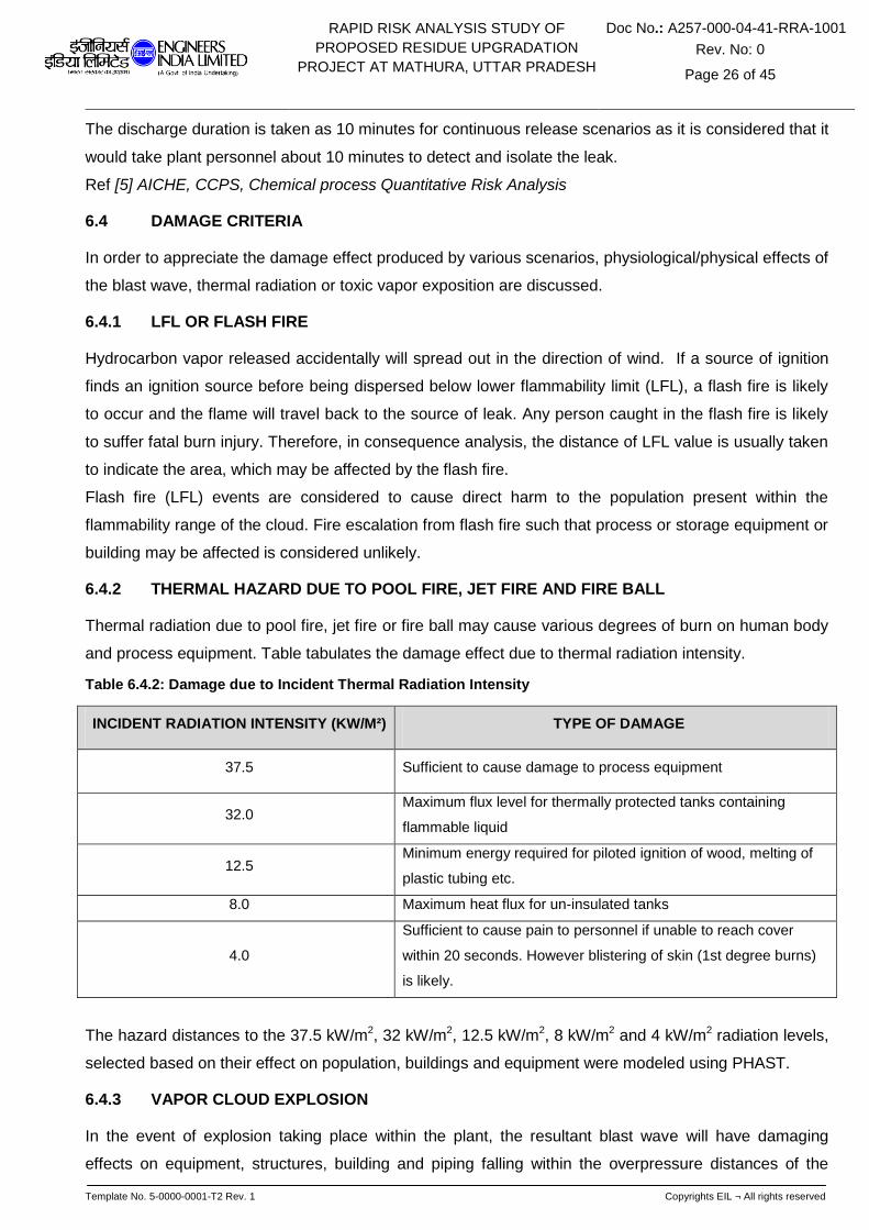
6.4.2 THERMAL HAZARD DUE TO POOL FIRE, JET FIRE AND FIRE BALL
Thermal radiation due to pool fire, jet fire or fire ball may cause various degrees of burn on human body
and process equipment. Table tabulates the damage effect due to thermal radiation intensity.
Table 6.4.2: Damage due to Incident Thermal Radiation Intensity
INCIDENT RADIATION INTENSITY (KW/M²) TYPE OF DAMAGE
37.5 Sufficient to cause damage to process equipment
32.0 Maximum flux level for thermally protected tanks containing
flammable liquid
12.5 Minimum energy required for piloted ignition of wood, melting of
plastic tubing etc.
8.0 Maximum heat flux for un-insulated tanks
4.0
Sufficient to cause pain to personnel if unable to reach cover
within 20 seconds. However blistering of skin (1st degree burns)
is likely.
The hazard distances to the 37.5 kW/m2, 32 kW/m2, 12.5 kW/m2, 8 kW/m2 and 4 kW/m2 radiation levels,
selected based on their effect on population, buildings and equipment were modeled using PHAST.
6.4.3 VAPOR CLOUD EXPLOSION
In the event of explosion taking place within the plant, the resultant blast wave will have damaging
effects on equipment, structures, building and piping falling within the overpressure distances of the

RAPID RISK ANALYSIS STUDY OF
PROPOSED RESIDUE UPGRADATION
PROJECT AT MATHURA, UTTAR PRADESH
Doc No.: A257-000-04-41-RRA-1001
Rev. No: 0
Page 27 of 45
Template No. 5-0000-0001-T2 Rev. 1 Copyrights EIL ¬ All rights reserved
blast. Tanks, buildings, structures etc. can only tolerate low level of overpressure. Human body, by
comparison, can withstand higher overpressure. But injury or fatality can be inflicted by collapse of
building of structures. Table illustrates the damage effect of blast overpressure.
Table 6.4.3: Damage Effects of Blast Overpressure
BLAST OVERPRESSURE (PSI) DAMAGE LEVEL
5.0 Major structure damage
3.0 Oil storage tank failure
2.5 Eardrum rupture
2.0 Repairable damage, pressure vessels remain intact, light
structures collapse
1.0 Window pane breakage possible, causing some injuries
The hazard distances to the 5 psi, 3 psi and 2 psi overpressure levels, selected based on their effects on
population, buildings and equipment were modeled using PHAST.
6.4.4 TOXIC HAZARD
The inhalation of toxic gases can give rise to effects, which range in severity from mild irritation of the
respiratory tract to death. Lethal effects of inhalation depend on the concentration of the gas to which
people are exposed and on the duration of exposure. Mostly this dependence is nonlinear and as the
concentration increases, the time required to produce a specific injury decreases rapidly.
The hazard distances to Immediately Dangerous to Life and Health concentration (IDLH) limit is selected
to determine the extent of the toxic hazard created as the result of loss of containment of a toxic
substance.
6.5 CONSEQUENCE ANALYSIS OF THE SELECTED FAILURE CASES
This section discusses the consequences of selected failure scenario as listed in the previous section.
The consequence analysis hazard distances are reported in tabular form for all weather conditions as
an Annexure-I and are represented graphically in Annexure-II for all selected failure cases in a unit for
worst scenario. Please refer Annexure-I for hazardous distances and Annexure-II for graphical
representation.
6.5.1 NEW PROPOSED UNITS
6.5.1.1 NAPHTHA SPLITTER UNIT (NSU)
Large Hole in Bottom line of Naphtha Splitter Ovhd. Separator: It can be observed from the
consequence analysis (SL. No.1 & figure 6.5.1.1.1 A-D) of this failure scenario that LFL shall approach
to the Refinery Compound wall on south side and also extends into New HGU & OHCU. The Jet Fire

RAPID RISK ANALYSIS STUDY OF
PROPOSED RESIDUE UPGRADATION
PROJECT AT MATHURA, UTTAR PRADESH
Doc No.: A257-000-04-41-RRA-1001
Rev. No: 0
Page 28 of 45
Template No. 5-0000-0001-T2 Rev. 1 Copyrights EIL ¬ All rights reserved
Radiation Intensity of 37.5 & 12.5 Kw/m2 shall be affecting equipments in NSU as well as in OHCU. The
5 & 3 psi blast wave shall spread throughout OHCU and covering majority of equipments in New HGU,
moreover it shall also be crossing Refinery Compound wall on southern side and engulfing the total
truck parking & even extending beyond it. The 12.5 & 4 Kw/m2 Radiation intensity on account of Pool
Fire shall be limited to vicinity of the unit.
Naphtha Splitter Bottom Pump Instrument Tapping Failure: From outcomes of consequence modeling
(SL. No.2 & figure 6.5.1.1.2 A-D); it can be observed that LFL shall be crossing the Unit’s B/L and may
affect to new OHCU. The 37.5 & 12.5 Kw/m2 Radiation intensity on account of Jet & Pool Fire shall be
restricted with the unit and warranting no cause for concern. The 5 & 3 psi blast wave intensity shall be
affecting the equipments in New OHCU and adjacent new HGU unit.
6.5.1.2 VACUUM DISTILLATION UNIT (VDU)
Vacuum Diesel Product/IR Pump Instrument Tapping Failure: From the Consequence analysis (SL.
No.3 & figure 6.5.1.2.1 A-D) of this failure scenario it can be observed that the LFL shall be crossing the
unit’s B/L on western side. The 37.5 & 12.5 Kw/m2 Radiation intensity on account of Jet Fire shall be
extended beyond the unit but will not be affecting any nearby unit or tankages. The 5 & 3 psi blast wave
shall be spreading throughout the unit damaging all the equipments and extending up to Tank No.: 951,
952, 953 and 954.
In Addition the above case following additional case; Seal Failure of LVGO Product / IR Pump (SL. No.4
& figure 6.5.1.2.2 A-D) was modeled and it was observed that the outcome of consequence analysis
for this failure scenarios shall be limited to vicinity of leakage, mostly producing localized damage and
does not affects any nearby Storage / Unit.
6.5.1.3 HYDROGEN GENERATION UNIT (HGU)
Raw Naphtha Surge Drum Catastrophic Rupture: From the Incident Outcome Analysis (SL. No.5 &
figure 6.5.1.3.1 A-D) of this failure scenario, it can be observed that LFL shall be covering whole of New
HGU & OHCU and will be reaching upto Existing HGU, H2 Unit, H2 Storage Bullets. The 37.5 & 12.5
Kw/m2 Radiation intensity on account of Pool Fire shall be affecting some of the equipments in New
HGU, 12.5 Kw/m2 Radiation intensity may further extends and affects equipments in existing H2 Plant,
part of OHCU. The 5 & 3 psi blast waves shall be encompassing whole of New HGU & OHCU and
Existing H2 Bullets, H2 Plant, OHCU, HGU, CT’s & portion of DHDS Unit. However, H2S IDLH
Concentration shall be limited to vicinity of leakage.
In Addition the above case following more cases; Naphtha Feed Pump Seal Failure (SL. No.6 & figure
6.5.1.3.2 A-D) & Instrument Tapping Failure on top outlet line of Stripper Ovhd. Separator (SL. No.7 &
figure 6.5.1.3.2 A-D) were modeled and it was observed that the outcome of consequence analysis for
these failure scenarios shall be limited to vicinity of leakage and their affect zone is limited to B/L’s of the
Unit.
RAPID RISK ANALYSIS STUDY OF
PROPOSED RESIDUE UPGRADATION
PROJECT AT MATHURA, UTTAR PRADESH
Doc No.: A257-000-04-41-RRA-1001
Rev. No: 0
Page 29 of 45
Template No. 5-0000-0001-T2 Rev. 1 Copyrights EIL ¬ All rights reserved
In normal operation natural gas will be used as a feed and naphtha surge drum will not be in operation.
Naphtha as a feed shall be used occasionally. Hence the above failure scenarios have no major
concern.
6.5.1.4 SULPHUR RECOVERY UNIT (SRU)
Instrument Tapping Failure in Acid Gas K.O Drum-(TOXIC): From the consequence analysis (SL. No.8
& figure 6.5.1.4.1 A) of this failure scenario it can be observed that H2S IDLH concentration shall be
extended upto existing MSQ Unit, SRU Unit, New ETP Unit and MSQ-CR & its Substation, LPG Sphere
area Operator cabin, affecting personnel’s present in these buildings. Moreover the H2S IDLH
concentration may cross the Refinery Compound wall on western side and affecting the population
beyond compound wall, if present.
6.5.1.5 ONCE THROUGH HYDROCRACKER (OHCU)
Charge Pump Instrument Tapping Failure: From Consequence analysis (SL. No.9 & figure 6.5.1.5.1 A-
D) of this failure scenario, it can be inferred that the Flash Fire and 5 & 3 psi blast waves shall be
damaging equipments in OHCU & may extends upto New HGU Unit. The 37.5 & 12.5 Kw/m2 Radiation
intensity on account of Jet Fire shall be limited to immediate vicinity of the leak. However 12.5 Kw/m2
Radiation experienced on account of Pool Fire shall be crossing the unit’s B/L and may get spread up to
Compound wall on southern side and small portion of H2 Plant.
Stripper Ovhd Pump Instrument Tapping Failure: From the outcomes of consequence analysis (SL.
No.11 & figure 6.5.1.5.3 A-D) of this failure scenario it can be observed that LFL shall be extended up to
New HGU Unit. The 37.5 & 12.5 Kw/m2 Radiation intensity on account of Jet Fire may damage the
equipments in vicinity of leakage in OHCU and also extends up to nearby New HGU. The 5 & 3 psi blast
wave shall be affecting most of equipments in OHCU, New HGU and NSU. The H2S IDLH concentration
shall be covering almost all of the Process Units and associated CR’s & Substations and may even
crosses the Boundary wall on Southern & Eastern side of the Refinery affecting individuals present.
Product Fractionator Receiver Catastrophic Rupture: From the consequence graphs (SL. No.12 & figure
6.5.1.5.4 A-B) of this failure scenario, it can be observed that LFL shall spreading within the unit. The 5
psi blast wave shall be affecting all the equipments of New OHCU, NSU & HGU and even crosses the
Refinery Compound wall on southern side affecting Truck parking area. The 3 psi blast wave may
further propagate and affects equipments in H2 Plant & HGU Unit.
Kerosene Stripper Bottom Pump Instrument Tapping Failure: From the outcomes of consequence
analysis (SL. No.13 & figure 6.5.1.5.5 A-C) of this failure scenario it can be observed that LFL shall be
extended up to New HGU Unit. The 37.5 & 12.5 Kw/m2 Radiation intensity on account of Jet Fire affect
zone shall be limited to unit’s B/L itself. The 5 & 3 psi blast wave may damage most of the equipments
in OHCU and extends upto New HGU and may crosses unit’s B/L on western side also.

RAPID RISK ANALYSIS STUDY OF
PROPOSED RESIDUE UPGRADATION
PROJECT AT MATHURA, UTTAR PRADESH
Doc No.: A257-000-04-41-RRA-1001
Rev. No: 0
Page 30 of 45
Template No. 5-0000-0001-T2 Rev. 1 Copyrights EIL ¬ All rights reserved
Debutanizer Receiver Catastrophic Rupture: From the incident outcome analysis (SL. No.15 & figure
6.5.1.5.7 A-C) of this failure scenario, it can be observed that the Flash Fire affect zone shall be limited
to vicinity of B/L’s of unit itself. The 5 & 3 psi blast wave spreads in OHCU unit and also extends into
New HGU unit. The H2S IDLH concentration may extend beyond the unit’s B/L up to New HGU, Sub
Officers Residence, relocated Ware House & Store Shed, New CT’s, Proposed New CR for Slurry
Hydrocracker & SHCU and Existing DHDT Unit, DHDS Unit & their CR, Substation, Existing H2 Bullets,
OHCU, H2 Plant, HGU, Off Building, CT’s, Chemical House. The H2S IDLH concentration may also
extends beyond the Compound wall of Refinery on Southern side and affects population present there.
In Addition the above case following more cases; Recycle Gas Compressor Instrument Tapping Failure
(SL. No.10 & figure 6.5.1.5.2 A-C), Diesel Product Pump Seal Failure (SL. No.14 & figure 6.5.1.5.6 A-B)
were modeled and it was observed that the outcome of consequence analysis for these failure
scenarios shall be limited to vicinity of leakage and their affect zone is limited to B/L’s of the Unit.
6.5.1.6 RESID HYDROCRACKING UNIT
Recycle Gas Compressor Instrument Tapping Failure: From Incident Outcome Analysis (SL. No.16 &
figure 6.5.1.6.1 A-C) of this failure scenario, it can be observed that Flash Fire affect zone shall be
restricted within the unit. The 37.5 & 12.5 Kw/m2 Radiation intensity on account of Jet Fire shall also be
restricted with the unit. The 5 & 3 psi blast wave affect zone shall mostly be restricted with the unit and
may to the road no.XI near the unit in west side. H2S IDLH concentration shall also be restricted with the
unit warranting no cause for concern.
Fractionator Ovhd. Accumulator Catastrophic Rupture: From the consequence analysis (SL. No.17 &
figure 6.5.1.6.2 A-C) of this failure scenario it can be observed that LFL shall be spreading beyond the
B/L’s of the unit, extending up to New ETP, New SRU Block, New Control Room, LPG Spheres, PRU
Sphere, Mounded Bullets and may even cross the Compound wall on South side up to Marketing
Division & Truck Parking Area. The 5 & 3 psi blast wave shall be damaging all equipments in the unit &
may even spreads beyond the B/L’s of the unit covering New ETP, New Control Room, New SRU Block,
LPG Spheres, PRU Spheres, Mounded bullets, Fire Water Tank (186-T-01A/B/C), Existing HGU Unit,
Truck parking area, Marketing Division area. The 12.5 Kw/m2 Radiation intensity on account of Pool Fire
affect zone shall be limited to unit itself.
Naphtha Product Pump Instrument Tapping Failure: From the incident outcome analysis (SL. No.19 &
figure 6.5.1.6.4 A-C) of this failure scenario it can be observed that the LFL shall be spreading
throughout the unit and may approach to the New Control room. The 37.5 & 12.5 Kw/m2 Radiation
intensity on account of Jet Fire shall be limited to vicinity of units, mostly producing localized damages.
The 5 & 3 psi blast wave shall be spreading throughout the unit damaging all the equipments in the unit
and affects New Control Room, substation and marketing building.
In addition the above case following more cases; VGO Product Pump Instrument Tapping Failure (SL.
No.18 & figure 6.5.1.6.3 A-C) and Diesel Product Pump Seal Failure (SL. No.20 & figure 6.5.1.6.5 A-C)

RAPID RISK ANALYSIS STUDY OF
PROPOSED RESIDUE UPGRADATION
PROJECT AT MATHURA, UTTAR PRADESH
Doc No.: A257-000-04-41-RRA-1001
Rev. No: 0
Page 31 of 45
Template No. 5-0000-0001-T2 Rev. 1 Copyrights EIL ¬ All rights reserved
were modeled and it was observed that the outcome of consequence analysis for these failure
scenarios shall be limited to vicinity of leakage and their affect zone is limited to B/L’s of the Unit.
6.5.1.7 OFFSITES
Diesel Tank on Fire: From the consequence graph (SL. No. 35 & figure 6.5.1.7.1 A) of this failure
scenario it can be observed that 32 Kw/m2 Radiation intensity shall not be realized. The 8 Kw/m2
Radiation intensity shall be limited to tankage surrounding itself, not affecting other nearby tankages
present.
HVGO Tank On Fire: From the consequence analysis ((SL. No. 36 & figure 6.5.1.7.2 A) of this failure
scenario it can be observed that 32 Kw/m2 Radiation intensity shall not be realized. The 8 Kw/m2
Radiation intensity shall be limited to tankage vicinity, not affecting other surrounding tankages.
LPG pump instrument tapping failure (LPG pump house): It will be evident from the results ((SL. No. 34
& figure 6.5.1.7.3 A-C) obtained that the consequences of flash fire, jet fire, & overpressure due to
instrument tapping failure on discharge line will be realized. The flash fire would cover the PH, LPG
sphere (070-V-01) and may approach to the new SRU and Resid Hydrocracking unit. Blast
overpressure of 5, 3 would affect the new SRU and Resid Hydrocracking unit partially. The thermal
radiation due to jet fire and pool fire of radiation intensity of 37.5kw/m2 and 12.5 kw/m2 would affect the
pump house and LPG sphere (070-V-01).
6.5.1.8 COOLING TOWER (CT)
Chlorine Toner Leakage: From the of consequence analysis (SL. No. 37 & figure 6.5.1.8.1 A) of this
failure scenario, it can be observed that any leakage from Chlorine Toner shall be going to affect the
total area under Mathura Refinery and even beyond the Compound walls of Refinery.
6.5.2 REVAMPED UNITS
6.5.2.1 CRUDE DISTILLATION UNIT (CDU)
Crude Charge Pump Instrument Tapping Failure: From Consequence Analysis (SL. No. 21 & figure
6.5.2.1.1 A-C) of this failure scenario, it can be observed that LFL is spreading beyond the B/L’s of the
Unit but not reaching up to any Unit/ Storage/ Facility. The 37.5 & 12.5 Kw/m2 Radiation intensity on
account of Jet Fire is also limited to B/L’s of the Unit, mostly producing localized damages. The 5 & 3 psi
blast wave is spreading within the Unit and crossing the Unit’s B/L on Northern & Western side affecting
Substation-8
Large Hole in Bottom Line of Atmospheric Column Reflux Drum: From Incident Outcome Analysis of
this failure scenario (SL. No. 22 & figure 6.5.2.1.3 A-D), it can be observed that Flash Fire affect zone is
getting extended beyond the Unit and extending up to VBU, CRU, Portion of FCC. The 37.5 & 12.5
Kw/m2 Radiation intensity on account of Jet Fire is spreading up to VBU, producing localized damage.
The 5 psi blast wave is damaging all of the equipments in CDU and affect zone is extended up to VBU,
RAPID RISK ANALYSIS STUDY OF
PROPOSED RESIDUE UPGRADATION
PROJECT AT MATHURA, UTTAR PRADESH
Doc No.: A257-000-04-41-RRA-1001
Rev. No: 0
Page 32 of 45
Template No. 5-0000-0001-T2 Rev. 1 Copyrights EIL ¬ All rights reserved
CRU, FCC, Portion of MSQ, Main CR, CRU Substation, Substation-8, CT’s & Tank nos.: 951, 952, 953,
954, 955, 956. The 3 psi blast wave further propagates & affects Tank nos.: 957, 958, 404, 002 and Fire
Water Tank: 186-T-01A. The 12.5 Kw/m2 Radiation intensity on account of Pool Fire is limited to leakage
source only, mostly producing localized damage.
Naphtha Stabilizer Reflux Drum Catastrophic Rupture: From the outcomes of Consequence Analysis
(SL. No. 26 & figure 6.5.2.1.6 A-B) of this failure scenario, it can be observed that LFL is restricted to
B/L’s of the Unit. The 5 & 3 psi blast waves are spreading throughout the unit and even beyond B/L’s of
the unit majorly affecting VBU, CRU Main Control Room, CRU Substation, Substation-8 and Tanks No.:
951, 953, 954.
Stabilizer Reflux Pump Instrument Tapping Failure: From the consequence graphs (SL. No. 27 & figure
6.5.2.1.7 A-C) of this failure scenario, it can be observed that LFL is spreading within the unit. The 37.5
& 12.5 Kw/m2 Radiation intensity on account of Jet Fire is limited to vicinity of leak, mostly producing
localized damage. The 5 & 3 psi blast wave is mostly spreading within the Unit and affecting small
portion of VBU of Eastern side.
In Addition the above case following more cases; Crude Booster Pump Seal Failure ((SL. No. 22 &
figure 6.5.2.1.2 A-C), Kero Product Pump Seal Failure (SL. No. 24 & figure 6.5.2.1.4 A-C), LGO Product
Pump Instrument Tapping Failure (SL. No. 25 & figure 6.5.2.1.5 A-C) were modeled and it was
observed that the outcome of consequence analysis for these failure scenarios are limited to vicinity of
leakage and their affect zone is limited to B/L’s of the Unit.
6.5.2.2 DIESEL HYDROTREATING UNIT (DHDT)
Feed Surge Drum Catastrophic Rupture: From Consequence Analysis (figure 6.5.2.2.1 A-C) of this
failure scenario, it can be observed that LFL is partially spreading beyond the unit. The 37.5 Kw/m2
Radiation intensity due to Pool Fire is affecting DHDT CR, its substation, all equipments in DHDT &
majority in DHDS and crossing the Compound Wall of Refinery on Eastern Side. The 12.5 Kw/m2
Radiations intensity due to Pool Fire further extends up to Ware House, Existing OHCU, H2 Bullets and
New proposed CT’s. The 5 & 3 psi blast wave is crossing the Unit’s B/L but are not reaching up to any
Unit/ Storage/ Building.
Charge Pump Instrument Tapping Failure: From the Incident Outcome Analysis (SL. No. 28 & figure
6.5.2.2.2 A-C) of this Failure Scenario, it can be observed that LFL is crossing the Unit’s B/L and
reaching up to DHDT CR & DHDS.
The 37.5 & 12.5 Kw/m2 Radiation intensity on account of Jet Fire is crossing the unit’s B/L but are not
reaching up to any Unit/ Storage/ Building. The 5 & 3 psi blast wave is spreading throughout the unit
affecting all the equipments and even beyond the B/L’s of the Unit affecting DHDS and DHDT CR &
Substation. The 37.5 & 12.5 Kw/m2 Radiation intensity on account of Pool Fire is crossing the unit’s B/L
affecting DHDS, DHDT CR, its Substation, New Proposed CT’s, H2 Storage, some portions of Existing
OHCU and crossing the Refinery Compound Wall on Eastern Side, affecting population present.

RAPID RISK ANALYSIS STUDY OF
PROPOSED RESIDUE UPGRADATION
PROJECT AT MATHURA, UTTAR PRADESH
Doc No.: A257-000-04-41-RRA-1001
Rev. No: 0
Page 33 of 45
Template No. 5-0000-0001-T2 Rev. 1 Copyrights EIL ¬ All rights reserved
Large Hole in the HP Cold Separator Bottom: From Consequence graphs (SL. No. 30 & figure 6.5.2.2.3
A-C) of this failure scenario, it can be observed that LFL is spreading beyond the unit and covering all of
the operating units of the refinery. It also crosses the Refinery compound wall on eastern side. The 37.5
& 12.5 Kw/m2 Radiation intensity on account of Jet Fire is damaging all the equipments within the unit &
crossing the unit’s B/L but is not reaching up to any Unit/ Storage/ Building. The 5 & 3 psi blast wave is
affecting all the Refinery units and affecting storages also. It also crosses the Refinery compound wall
on Eastern & Southern side affecting individuals present over there. H2S IDLH concentration spreads
beyond the B/L’s of the unit and extends up to CRU, FCC, Laboratory, Fire Station, Admin Building ,
Project Building, Warehouse, Workshop, Training Hall, Community Hall, New proposed Store Shed,
proposed warehouse, proposed store, proposed CT, proposed New HGU, proposed New OHCU,
existing OHCU, H2 Unit, New HGU, CT’s , Fire water tanks.
Recycle Gas Compressor Instrument Tapping Failure: From the outcomes of Consequence Analysis
(SL. No. 31 & figure 6.5.2.2.4 A-D) of this failure scenario, it can be observed that LFL is crossing the
unit’s B/L but not reaching upto any other Unit/Storage. The 37.5 & 12.5 Kw/m2 Radiation intensity on
account of Jet Fire is crossing the unit’s B/L but not reaching up to any other facility mostly producing
localized damage. The 5 & 3 psi blast wave is spreading throughout the unit affecting majorly all
equipments and even beyond the B/L’s of the Unit affecting nearby DHDS Unit. The H2S IDLH
concentration affect zone is limited to immediate vicinity of leakage, mostly producing localized damage.
In Addition the above case following more case; Stripper Reflux Pump Seal Failure (SL. No. 32 & figure
6.5.2.2.5 A-C) and Instrument Tapping Failure on Ovhd. line of HP Amine Absorber KOD (figure SL. No.
33 & 6.5.2.2.6 A-C) were modeled and it was observed that the outcome of consequence analysis for
this failure scenario is limited to vicinity of leakage and its affect zone is limited to B/L’s of the Unit.

RAPID RISK ANALYSIS STUDY OF
PROPOSED RESIDUE UPGRADATION
PROJECT AT MATHURA, UTTAR PRADESH
Doc No.: A257-000-04-41-RRA-1001
Rev. No: 0
Page 34 of 45
Template No. 5-0000-0001-T2 Rev. 1 Copyrights EIL ¬ All rights reserved
SECTION-7
7.1 LIST OF LAST MAJOR REFINERY INCIDENTS GLOBALLY IN LAST 10 YEARS
Today the refining industry finds itself the subject of a range of major accidents (explosions, fires,
emissions of dangerous materials, casualties) that have occurred over the last decade from which
important lessons can be learnt. The purpose of this list is to illustrate what the industry should learn
from recent major accidents and in such a way create opportunities for the future to prevent new major
accidents.
7.1.1 FIRE AND EXPLOSION AT CHEVRON RICHMOND REFINERY, USA
On August 6, 2012, the Chevron U.S.A. Inc. Refinery in Richmond, California, experienced a
catastrophic pipe failure in the #4 Crude Unit. The pipe ruptured, releasing flammable, hydrocarbon
process fluid which partially vaporized into a large vapor cloud that engulfed nineteen Chevron
employees. All of the employees escaped, narrowly avoiding serious injury. The flammable portion of
the vapor cloud ignited just over two minutes after the pipe ruptured. The ignition and subsequent
continued burning of the hydrocarbon process fluid resulted in a large plume of unknown and
unquantified particulates and vapor traveling across the Richmond, California, area. In the weeks
following the incident, approximately 15,000 people from the surrounding area sought medical treatment
due to the release. Testing commissioned by the U.S. Chemical Safety and Hazard Investigation Board
(CSB) and the California Division of Occupational Safety and Health (Cal/OSHA) determined that the
pipe failed due to thinning caused by sulfidation corrosion, a common damage mechanism in refineries.
As a result of the incident, the Chevron Richmond Refinery crude unit remains out of commission over
eight months later.
7.1.2 FIRE AND EXPLOSION AT AMUAY REFINERY, VENEZUELA
August 2012 - An explosion followed by fire tears through Venezuela's biggest refinery, killing 39
people, wounding dozens more and halting operations at the Amuay Refinery in Venezuela in the worst
accident to hit the OPEC nation's oil industry
7.1.3 TERMINAL FIRE AND EXPLOSION AT JAIPUR (INDIA)
A devastating fire/explosion accident occurred on 29 September, 2009 at about 7.30 pm in the POL
installation of M/S Indian Oil Corporation at Sitapura (Sanganer), Jaipur, and Rajasthan killing 11
persons and injuring 45. The product loss of around 60,000 KL has been reported. In this accident the
entire installation was totally destroyed and buildings in the immediate neighborhood were also heavily
damaged.
7.1.4 BUNCEFIELD TANK FARM FIRE AND EXPLOSION, UK
On 11 December, 2005 at approximately midnight, the terminal was closed to tankers and a stock check
of products was carried out. When this was completed at around 01.30, no abnormalities were reported.
From approximately 03.00, the level gauge for Tank 912 recorded an unchanged reading. However,

RAPID RISK ANALYSIS STUDY OF
PROPOSED RESIDUE UPGRADATION
PROJECT AT MATHURA, UTTAR PRADESH
Doc No.: A257-000-04-41-RRA-1001
Rev. No: 0
Page 35 of 45
Template No. 5-0000-0001-T2 Rev. 1 Copyrights EIL ¬ All rights reserved
filling of Tank 912 continued at a rate of around 550 m3/hour. Calculations show that at around 05.20,
Tank 912 would have been completely full and starting to overflow. Evidence suggests that the
protection system which should have automatically closed valves to prevent any more filling did not
operate. From 05.20 onwards, continued pumping caused fuel to cascade down the side of the tank and
through the air, leading to the rapid formation of a rich fuel/air mixture that collected in bund A. At 05.38,
CCTV footage shows vapour from escaped fuel start to flow out of the north-west corner of bund A
towards the west. The vapour cloud was about 1 m deep. At 05.46, the vapour cloud had thickened to
about 2 m deep and was flowing out of bund A in all directions. Between 05.50 and 06.00, the pumping
rate down the T/K South pipeline to Tank 912 gradually rose to around 890 m3/hour. By 05.50, the
vapour cloud had started flowing off site near the junction of Cherry Tree Lane and Buncefield Lane,
following the ground topography. It spread west into Northgate House and Fuji car parks and towards
Catherine House. At 06.01, the first explosion occurred, followed by further explosions and a large fire
that engulfed over 20 large storage tanks. The main explosion event was centered on the car parks
between the HOSL West site and the Fuji and Northgate buildings. The exact ignition points are not
certain, but are likely to have been a generator house in the Northgate car park and the pump house on
the HOSL West site. At the time of ignition, the vapour cloud extended to the west almost as far as
Boundary Way in the gaps between the 3-Com, Northgate and Fuji buildings; to the north west it
extended as far as the nearest corner of Catherine House. It may have extended to the north of the
HOSL site as far as British Pipelines Agency (BPA) Tank 12 and may have extended south across part
of the HOSL site, but not as far as the tanker filling gantry. To the east it reached the BPA site.
7.1.5 EXPLOSION AND FIRE AT FORMOSA PLASTICS, ILLINOIS, USA
On April 23, 2004, five workers were fatally injured and two others were seriously injured when an
explosion occurred in a polyvinyl chloride (PVC) production unit at Formosa Plastics in Illiopolis, Illinois,
east of Springfield. The explosion followed a release of highly flammable vinyl chloride, which ignited.
The explosion forced a community evacuation and lighted fires that burned for several days at the plant.
7.1.6 EXPLOSION AND FIRE AT BP TEXAS REFINERY, USA
On March 23, 2005, fifteen people were killed and 180 injured following an explosion at this 460,000
bbl/d refinery. The explosion occurred in the isomerisation unit which had been shut down for its annual
maintenance. This unit was gradually being brought back on stream when the incident occurred. Further
investigations concentrated on a raffinate splitter as evidence pointed to a release of a flammable liquid
and vapor in that area of the plant. The distillation equipment was also being restarted following
maintenance work on the reactor. Many of the dead had been attending a meeting in a pair of trailers
near the area at the time of the explosion. The exact ignition source remains unknown but evidence
points to sources on the ground. Witnesses reported that there was a large hydrocarbon liquid and
vapor release from a 30 meter high vent stack moments before the ignition.

RAPID RISK ANALYSIS STUDY OF
PROPOSED RESIDUE UPGRADATION
PROJECT AT MATHURA, UTTAR PRADESH
Doc No.: A257-000-04-41-RRA-1001
Rev. No: 0
Page 36 of 45
Template No. 5-0000-0001-T2 Rev. 1 Copyrights EIL ¬ All rights reserved
SECTION-8
CONCLUSIONS AND RECOMMENDATIONS
The major conclusions and recommendations arising out of the Rapid Risk analysis study for the IOCL
Mathura Refinery are summarized below. This is based on the detail analysis given in Sections – 6.
NEW PROPOSED UNITS
NSU: Large Hole in Bottom line of Naphtha Splitter Ovhd. Separator: It can be observed from
consequence analysis of this failure scenario that LFL shall approach to the Refinery Compound wall on
south side and also extends into New HGU & OHCU. The Jet Fire Radiation Intensity of 37.5 & 12.5
Kw/m2 shall be affecting equipments in NSU as well as in OHCU. The 5 & 3 psi blast wave shall spread
throughout OHCU and covering majority of equipments in New HGU, moreover it shall also be crossing
Refinery Compound wall on southern side and engulfing the total truck parking & even extending
beyond it. The 12.5 & 4 Kw/m2 Radiation intensity on account of Pool Fire shall be limited to vicinity of
the unit.
As LFL shall be reaching up to the South Side Compound wall of the Refinery and 5 & 3 psi blast wave
shall be affecting Truck parking area, it is recommended to consider relocation of the Truck Parking
Area.
VDU: Vacuum Diesel Product/IR Pump Instrument Tapping Failure: From the Consequence
analysis of this failure scenario it can be observed that the LFL shall be crossing the unit’s B/L on
western side. The 37.5 & 12.5 Kw/m2 Radiation intensity on account of Jet Fire shall be extended
beyond the unit but will not be affecting any nearby unit or tankages. The 5 & 3 psi blast wave shall be
spreading throughout the unit damaging all the equipments and extending up to Tank No.: 951, 952,
953 and 954.
The affected tankage should be provided with suitable fire fighting measures. In order to prevent
secondary incident arising from this failure, it is recommended that fire monitors and hydrant provided
around the tanks to be regularly checked to ensure that they are functional. Less hazardous equipments
(typically RCO pumps, hot oil system etc.) to be located on western side block of CDU.
SRU: Instrument Tapping Failure in Acid Gas K.O Drum-(TOXIC): From the consequence graph of
this failure scenario it can be observed that H2S IDLH concentration shall be extended upto existing
MSQ Unit, SRU Unit, New ETP Unit and MSQ-CR & its Substation, LPG Sphere area Operator cabin,
affecting personnel’s present in these buildings. Moreover the H2S IDLH concentration may cross the
Refinery Compound wall on western side and affecting the population beyond compound wall, if
present.
As H2S IDLH concentration shall be extended up to existing MSQ Unit, SRU Unit, any Temporary
Operator Cabin present in these units is to be removed / relocated. As MSQ-CR & its Substation are
positively pressurized, hence personnel in these building shall not be affected by H2S IDLH
concentration. Either relocation or positive pressurization of LPG Sphere area Operator cabin near LPG

RAPID RISK ANALYSIS STUDY OF
PROPOSED RESIDUE UPGRADATION
PROJECT AT MATHURA, UTTAR PRADESH
Doc No.: A257-000-04-41-RRA-1001
Rev. No: 0
Page 37 of 45
Template No. 5-0000-0001-T2 Rev. 1 Copyrights EIL ¬ All rights reserved
MCC room is recommended. Moreover, H2S detectors are to be installed at strategic locations. DMP &
ERP should include instructions for Human evacuations from above specified areas on priority, in any
case of leakage of H2S from SRU.
OHCU: Stripper Ovhd Pump Instrument Tapping Failure: From the outcomes of consequence
analysis of this failure scenario it can be observed that LFL shall be extended up to New HGU Unit. The
37.5 & 12.5 Kw/m2 Radiation intensity on account of Jet Fire may damage the equipments in vicinity of
leakage in OHCU and also extends up to nearby New HGU. The 5 & 3 psi blast wave shall be affecting
most of equipments in OHCU, New HGU and NSU. The H2S IDLH concentration shall be affecting
DHDT/DHDS control room, proposed new control room and substation, process cooling water control
room, substation-151/11, offsite utility substation, office building, drinking & fresh water control room,
eco office and may even crosses the Boundary wall on Southern side of the Refinery affecting
individuals present.
DHDT/DHDS control room and proposed ‘new control room & substation’ are positively pressurized;
hence personnel in these building shall not be affected by H2S IDLH concentration.
It is recommended to install H2S detectors with sirens at strategic location in the plant in the event of any
such leakage to alert personnel present in the existing building viz. process cooling water control room,
drinking and fresh water control room, office building and Eco office and evacuation procedures should
be in place to evacuate personnel.
Since H2S IDLH concentration crosses boundary wall on southern side, it is also recommended to install
H2S detectors with sirens on south side of the unit and DMP should address emergency evacuation
procedures in case of any such leakage. Since the truck parking area is located in the south side
outside plant boundary hence it is recommended to consider the relocation of Truck Parking Area.

RAPID RISK ANALYSIS STUDY OF
PROPOSED RESIDUE UPGRADATION
PROJECT AT MATHURA, UTTAR PRADESH
Doc No.: A257-000-04-41-RRA-1001
Rev. No: 0
Page 38 of 45
Template No. 5-0000-0001-T2 Rev. 1 Copyrights EIL ¬ All rights reserved
OHCU: Product Fractionator Receiver Catastrophic Rupture: From the consequence graphs of this
failure scenario, it can be observed that LFL shall spreading within the unit. The 5 psi blast wave shall
be affecting all the equipments of New OHCU, NSU & HGU and even crosses the Refinery Compound
wall on southern side affecting Truck parking area. The 3 psi blast wave may further propagate and
affects equipments in H2 Plant & HGU Unit.
Though LFL shall be restricted to B/L’s of the Unit, relocation of Truck Parking Area to be looked upon
as it is getting affected by 5 and 3 psi blast wave.
OHCU: Debutanizer Receiver Catastrophic Rupture: From the incident outcome analysis of this
failure scenario, it can be observed that the Flash Fire affect zone shall be limited to vicinity of B/L’s of
unit itself. The 5 & 3 psi blast wave spreads in OHCU unit and also extends into New HGU unit. The H2S
IDLH concentration may extend beyond the unit’s B/L up to New HGU, Sub Officers Residence,
relocated Ware House & Store Shed, New CT’s, Proposed New CR for Slurry Hydrocracker & SHCU
and Existing DHDT Unit, DHDS Unit & their CR, Substation, Existing H2 Bullets, OHCU, H2 Plant, HGU,
Off Building, CT’s, Chemical House. The H2S IDLH concentration may also extends beyond the
Compound wall of Refinery on Southern side and affects population present there.
It is recommended to install H2S detectors with sirens on East & South side B/L of the unit and DMP
should address emergency evacuation procedures in case of any such scenario. The manned building
within the affect zone of H2S IDLH should be evacuated on priority.
RESID HYDROCRACKING UNIT: Fractionator Ovhd. Accumulator Catastrophic Rupture: From
the consequence analysis of this failure scenario it can be observed that LFL shall be spreading beyond
the B/L’s of the unit, extending up to New ETP, New SRU Block, New Control Room, LPG Spheres,
PRU Sphere, Mounded Bullets and may even cross the Compound wall on South side up to Marketing
Division & Truck Parking Area. The 5 & 3 psi blast wave shall be damaging all equipments in the unit &
may even spreads beyond the B/L’s of the unit covering New ETP, New Control Room, New SRU Block,
LPG Spheres, PRU Spheres, Mounded bullets, Fire Water Tank (186-T-01A/B/C), Existing HGU Unit,
Truck parking area, Marketing Division area. The 12.5 Kw/m2 Radiation intensity on account of Pool Fire
affect zone shall be limited to unit itself.
As LFL shall be reaching up to Truck Parking Area and it is also getting affected by 5 & 3 psi blast
wave, it is recommended to consider relocation / removal of Truck Parking Area.
RESID HYDROCRACKING UNIT: Naphtha Product Pump Instrument Tapping Failure: From the
incident outcome analysis of this failure scenario it can be observed that the LFL shall be spreading
throughout the unit and may approach to the New Control room. The 37.5 & 12.5 Kw/m2 Radiation
intensity on account of Jet Fire shall be limited to vicinity of units, mostly producing localized damages.
The 5 & 3 psi blast wave shall be spreading throughout the unit damaging all the equipments in the unit
and affects New Control Room, substation and marketing building.

RAPID RISK ANALYSIS STUDY OF
PROPOSED RESIDUE UPGRADATION
PROJECT AT MATHURA, UTTAR PRADESH
Doc No.: A257-000-04-41-RRA-1001
Rev. No: 0
Page 39 of 45
Template No. 5-0000-0001-T2 Rev. 1 Copyrights EIL ¬ All rights reserved
As Proposed New Control Room shall be getting affected by 5 & 3 psi blast wave, it is recommended to
be made Blast Proof with Positive Pressurization.
CT: Chlorine Toner Leakage: From the graphs of consequence analysis of this failure scenario, it can
be observed that any leakage from Chlorine Toner shall be going to affect the total area under Mathura
Refinery and even beyond the Compound walls of Refinery.
As Chlorine IDLH is affecting all the individuals inside Mathura Refinery and even beyond its Compound
wall, it is suggested to substitute / replace Chlorine with some other safer alternative viz. ClO2. In
absence of replacement it is recommended to install Cl2 detectors with sirens at strategic locations and
train people for emergency evacuation in case of Cl2 leakage. IOCL should also involve State level
authorities / District Administration in trainings/Mock drills, as Cl2 IDLH affect zone is extended beyond
the Compound Wall of Refinery, population in vicinity of the Refinery are to be informed about ill-effects
of Cl2.
REVAMPED UNITS
CDU: Large Hole in Bottom Line of Atmospheric Column Reflux Drum: From Incident Outcome
Analysis of this failure scenario, it can be observed that Flash Fire affect zone is getting extended
beyond the Unit and extending up to VBU, CRU, Portion of FCC. The 37.5 & 12.5 Kw/m2 Radiation
intensity on account of Jet Fire is spreading up to VBU, producing localized damage. The 5 psi blast
wave is damaging all of the equipments in CDU and affect zone is extended up to VBU, CRU, FCC,
Portion of MSQ, Main CR, CRU Substation, Substation-8, CT’s & Tank nos.: 951, 952, 953, 954, 955,
956. The 3 psi blast wave further propagates & affects Tank nos.: 957, 958, 404, 002 and Fire Water
Tank: 186-T-01A. The 12.5 Kw/m2 Radiation intensity on account of Pool Fire is limited to leakage
source only, mostly producing localized damage.
5 psi blast wave is affecting Main CR which is already of Blast proof construction. The affected tankage
should be provided with suitable fire fighting measures. In order to prevent secondary incident arising
from this failure, it is recommended that fire monitor and hydrant provided around the tanks to be
regularly checked to ensure that they are functional. Proper routine check to be ensured in the area to
prevent presence of any potential ignition source in the vicinity.
CDU: Naphtha Stabilizer Reflux Drum Catastrophic Rupture: From the outcomes of Consequence
Analysis of this failure scenario, it can be observed that LFL is restricted to B/L’s of the Unit. The 5 & 3
psi blast waves are spreading throughout the unit and even beyond B/L’s of the unit majorly affecting
VBU, CRU Main Control Room, CRU Substation, Substation-8 and Tanks No.: 951, 953 and 954.
Ensure the blast proof construction of CRU Main Control Room & its Substation, Substation-8.
The affected tankage should be provided with suitable fire fighting measures. In order to prevent
secondary incident arising from this failure, it is fire monitor and hydrant provided around the tanks to be
regularly checked to ensure that they are functional.

RAPID RISK ANALYSIS STUDY OF
PROPOSED RESIDUE UPGRADATION
PROJECT AT MATHURA, UTTAR PRADESH
Doc No.: A257-000-04-41-RRA-1001
Rev. No: 0
Page 40 of 45
Template No. 5-0000-0001-T2 Rev. 1 Copyrights EIL ¬ All rights reserved
DHDT: Large Hole in the HP Cold Separator Bottom: From Consequence graphs of this failure
scenario, it can be observed that LFL is spreading beyond the unit and covering all of the operating
units of the refinery. It also crosses the Refinery compound wall on eastern side. The 37.5 & 12.5 Kw/m2
Radiation intensity on account of Jet Fire is damaging all the equipments within the unit & crossing the
unit’s B/L but is not reaching up to any Unit/ Storage/ Building. The 5 & 3 psi blast wave is affecting all
the Refinery units and affecting storages also. It also crosses the Refinery compound wall on Eastern &
Southern side affecting individuals present over there. H2S IDLH concentration spreads beyond the
B/L’s of the unit and extends up to CRU, FCC, Laboratory, Fire Station, Admin Building , Project
Building, Warehouse, Workshop, Training Hall, Community Hall, New proposed Store Shed, proposed
warehouse, proposed store, proposed CT, proposed New HGU, proposed New OHCU, existing OHCU,
H2 Unit, New HGU, CT’s , Fire water tanks.
Though the Failure Frequency of such an incident is remote, H2S detectors at suitable locations within
the unit shall be ensured. The virtue of extent of damages by this case can be utilized for making an
efficient DMP. The probability of such an incident can be further reduced by efficient monitoring of
vessel internals during shut-down.
GENERAL RECOMMENDATIONS
It is recommended to interchange the locations of new proposed OHCU and HGU in order to
further reduce the hazard beyond the southern side of the compound wall of the refinery.
It is recommended that the HP section and toxic section are to be located towards the north east
side of the unit in equipment layout of Resid Hydrocracking unit on account of close proximity of
LPG and propylene sphere.
In the event of any leakage from existing LPG P/H which may affect adjacent new unit (Resid
Hydrocracking Unit) in case if the release gas finds any ignition source in its path. It is therefore
recommended to restrict the traffic movement on all the roads around the existing sphere area to
avoid the presence of ignition source.
Hydrocarbon detector with alarm shall be provided at strategic location on west side of the
sphere in the event of any leakage from existing LPG P/H which may get ignited because of
ignition source from moving rail wagon. Hence therefore it is recommended to stop the rail
wagon movement immediately on actuation of hydrocarbon detector alarm.
Proper barricading during construction phase of new units of proposed residue Upgradation
project from the existing units to be done.
Proper checking of contract people for Smoking or Inflammable materials to be ensured at entry
gates to avoid presence of any unidentified source of ignition.
The vehicles entering the Refinery complex should be fitted with spark arrestors as a mandatory
item.

RAPID RISK ANALYSIS STUDY OF
PROPOSED RESIDUE UPGRADATION
PROJECT AT MATHURA, UTTAR PRADESH
Doc No.: A257-000-04-41-RRA-1001
Rev. No: 0
Page 41 of 45
Template No. 5-0000-0001-T2 Rev. 1 Copyrights EIL ¬ All rights reserved
In order to prevent secondary incident arising from any failure scenario, it is recommended that
sprinklers and other protective devices provided on the tanks to be regularly checked to ensure
that they are functional.
Emergency security / evacuation drills to be organized at organization level to ensure
preparation of the personnel’s working in IOCL-MR for handling any extreme situation.
MITIGATING MEASURES
Mitigating measures are those measures in place to minimize the loss of containment event and,
hazards arising out of Loss of containment. These include:
Rapid detection of an uncommon event (HC leak, Toxic gas leak, Flame etc) and alarm
arrangements and development of subsequent quick isolation mechanism for major inventory.
Measures for controlling / minimization of Ignition sources inside the Refinery complex.
Active And Passive Fire Protection for critical equipments and major structures
Effective Emergency Response plans to be in place
Detection and isolation
IGNITION CONTROL
Ignition control will reduce the likelihood of fire events. This is the key for reducing the risk within
facilities that process flammable materials. As part of mitigation measure it strongly
recommended to consider minimization of Smoking booths in the Refinery
ESCAPE ROUTES
Ensure windsocks throughout the site to ensure visibility from all locations. This will enable
people to escape upwind or crosswind from flammable / toxic releases. Sufficient escape routes
from the site should be provided to allow redundancy in escape from all areas.
Ensure sign boards marking emergency/safe roads to be taken during any exigencies.
PREVENTIVE MAINTENANCE FOR CRITICAL EQUIPMENTS
In order to further reduce the probability of catastrophes efficient monitoring of vessel internals
during shut-down to be carried out for Surge Drums & Reflux drums and critical vessels whose
rupture would lead to massive consequences.
OTHERS
Closed sampling system to be considered for pressurized services like Propylene etc.
Whenever a person visits for sampling and maintenance etc. in H2S prone area, it is to be
ensured to carry portable H2S detector.
Ensure breathing apparatus at strategic locations inside Refinery.

RAPID RISK ANALYSIS STUDY OF
PROPOSED RESIDUE UPGRADATION
PROJECT AT MATHURA, UTTAR PRADESH
Doc No.: A257-000-04-41-RRA-1001
Rev. No: 0
Page 42 of 45
Template No. 5-0000-0001-T2 Rev. 1 Copyrights EIL ¬ All rights reserved
MITIGATING MEASURES
Mitigating measures are those measures in place to minimize the loss of containment event and,
hazards arising out of Loss of containment. These include:
Rapid detection of an uncommon event (HC leak, Toxic gas leak, Flame etc) and alarm
arrangements and development of subsequent quick isolation mechanism for major inventory.
Measures for controlling / minimization of Ignition sources inside the Refinery complex.
Active And Passive Fire Protection for critical equipments and major structures
Effective Emergency Response plans to be in place
Detection and isolation
IGNITION CONTROL
Ignition control will reduce the likelihood of fire events. This is the key for reducing the risk within
facilities that process flammable materials. As part of mitigation measure it strongly
recommended to consider minimization of Smoking booths in the Refinery
ESCAPE ROUTES
Ensure windsocks throughout the site to ensure visibility from all locations. This will enable
people to escape upwind or crosswind from flammable / toxic releases. Sufficient escape routes
from the site should be provided to allow redundancy in escape from all areas.
Ensure sign boards marking emergency/safe roads to be taken during any exigencies.
PREVENTIVE MAINTENANCE FOR CRITICAL EQUIPMENTS
In order to further reduce the probability of catastrophes efficient monitoring of vessel internals
during shut-down to be carried out for Surge Drums & Reflux drums and critical vessels whose
rupture would lead to massive consequences.
OTHERS
Closed sampling system to be considered for pressurized services like Propylene etc.
Whenever a person visits for sampling and maintenance etc. in H2S prone area, it is to be
ensured to carry portable H2S detector.
Ensure breathing apparatus at strategic locations inside Refinery

RAPID RISK ANALYSIS STUDY OF
PROPOSED RESIDUE UPGRADATION
PROJECT AT MATHURA, UTTAR PRADESH
Doc No.: A257-000-04-41-RRA-1001
Rev. No: 0
Page 43 of 45
Template No. 5-0000-0001-T2 Rev. 1 Copyrights EIL ¬ All rights reserved
GLOSSARY
CASUALTY Someone who suffers serious injury or worse i.e. including fatal injuries. As
a rough guide fatalities are likely to be half the total casualties. But this may
vary depending on the nature of the event.
HAZARD A chemical or physical condition with the potential of causing damage.
FLAMMABILITY LIMITS In fuel-air systems, a range of compositions exists inside which a (UFL –
LFL) flame will propagate substantial distance from an ignition source. The
limiting fuel concentrations are termed as Upper flammability or explosives
limit (Fuel concentrations exceeding this are too rich) and Lower
flammability or explosives limit (Fuel concentrations below this are too lean).
FLASH FIRE The burning of a vapor cloud at very low flame propagation speed.
Combustion products are generated at a rate low enough for expansion to
take place easily without significant overpressure ahead or behind the flame
front. The hazard is therefore only due to thermal effects.
OVERPRESSURE Maximum pressure above atmosphere pressure experiences during the
passage of a blast wave from an explosion expressed in this report as
pounds per square inch (psi).
EXPLOSION A rapid release of energy, which causes a pressure discontinuity or shock
wave moving away from the source. An explosion can be produced by
detonation of a high explosive or by the rapid burning of a flammable gas
cloud. The resulting overpressure is sufficient to cause damage inside and
outside the cloud as the shock wave propagation into the atmosphere
beyond the cloud. Some authors use the term deflagration for this type of
explosion
DOMINO EFFECT The effect that loss of containment of one installation leads to loss of
containment of other installations

RAPID RISK ANALYSIS STUDY OF
PROPOSED RESIDUE UPGRADATION
PROJECT AT MATHURA, UTTAR PRADESH
Doc No.: A257-000-04-41-RRA-1001
Rev. No: 0
Page 44 of 45
Template No. 5-0000-0001-T2 Rev. 1 Copyrights EIL ¬ All rights reserved
EVENT TREE A logic diagram of success and failure combinations of events used to
identify accident sequences leading to all possible consequences of a given
initiating event.
TLV “Threshold limit value” is defined as the concentration of the substance in air
that can be breathed for five consecutive 8 hours work day (40 hours work
week) by most people without side effect.
STEL “Short Term Exposure Limit” is the maximum permissible average exposure
for the time period specified (15 minutes).
IDLH “Immediate Dangerous to Life and Health” is the maximum concentration
level from which one could escape within 30 minutes without any escape
impairing symptoms.
PASQUILL CLASS Classification to qualify the stability of the atmosphere, indicated by a letter
ranging from A, for very unstable, to F, for stable.
FREQUENCY The number of times an outcome is expected to occur in a given period of
time.

RAPID RISK ANALYSIS STUDY OF
PROPOSED RESIDUE UPGRADATION
PROJECT AT MATHURA, UTTAR PRADESH
Doc No.: A257-000-04-41-RRA-1001
Rev. No: 0
Page 45 of 45
Template No. 5-0000-0001-T2 Rev. 1 Copyrights EIL ¬ All rights reserved
REFERENCES
1. Classification of hazardous locations, A. W. Cox, F. P. Lees and M. L. Ang, Published by the
Institute of Chemical engineers, U. K.
2. The reference manual, Volume-II, Cremer & Warner Ltd. U. K. (Presently Entec).
3. Risk analysis of six potentially hazardous industrial objects in the Rijnmond area; A pilot study. A
report to the Rijnmond Public Authority. D. Riedel publishing company, U. K.
4. Loss prevention in the process industries, Hazard identification, Assessment and Control, Frank.
P. Lees (Vol. I, II & III), Published by Butterworth-Heinemann, U. K.
5. AICHE, CCPS, Chemical process Quantitative Risk Analysis
6. Guideline for Quantitative Risk assessment, ‘Purple book’.
7. Plot plan A260-000-1647-0001, Rev H.

ANNEXURE-I
CONSEQUENCE ANALYSIS HAZARD DISTANCES

ANNEXURE-II
FIGURES FOR CONSEQUENCE ANALYSIS

ANNEXURE-III
OVER ALL PLOT PLAN


![Resid Vectors[1]](https://img.pdfslide.net/doc/110x75/577d2aac1a28ab4e1ea9c7c5/resid-vectors1.jpg)