Embed Size (px)
Citation preview
8/3/2019 HBii2007 D01 OCT Overview
http://slidepdf.com/reader/full/hbii2007-d01-oct-overview 1/6
O v e r v i e w
D1
Baltimore Aircoil Company
Open cooling towers provide evaporative cooling for many types of systems. The specific application will
largely determine which BAC Cooling Tower is best suited for a project. The table on pages D5 and D6 is
intended as a general guide. Specific application assistance is available through your local BAC Representative.
Principle of Operation
Open cooling towers reject heat from water-cooled systems to the atmosphere. Hot water from the system
enters the cooling tower and is distributed over the fill (heat transfer surface). Air is induced or forced through
the fill, causing a small portion of the water to evaporate. This evaporation removes heat from the remaining
water, which is collected in the cold water basin and returned to the system to absorb more heat.
Each open cooling tower line, although operating under the same basic principle of operation, is arranged a
little differently. See the schematics on pages D5 and D6 for product specific details.
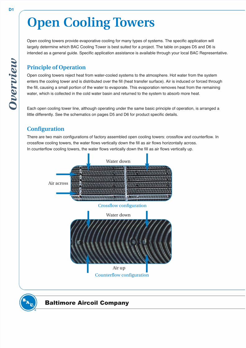
Configuration
There are two main configurations of factory assembled open cooling towers: crossflow and counterflow. In
crossflow cooling towers, the water flows vertically down the fill as air flows horizontally across.
In counterflow cooling towers, the water flows vertically down the fill as air flows vertically up.
Open Cooling Towers
Crossflow configuration
Water down
Air across
Counterflow configuration
Water down
Air up
8/3/2019 HBii2007 D01 OCT Overview
http://slidepdf.com/reader/full/hbii2007-d01-oct-overview 2/6
g
...because temperature matters™
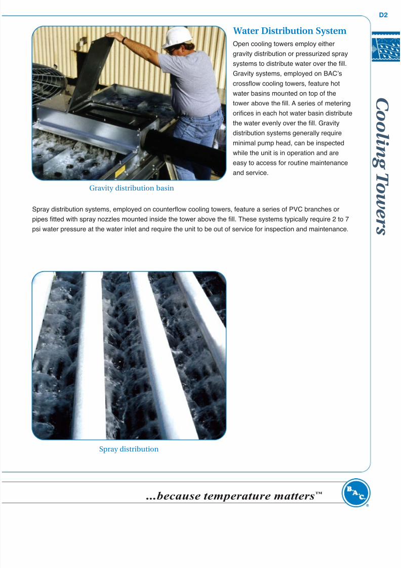
Water Distribution System
Open cooling towers employ either
gravity distribution or pressurized spray
systems to distribute water over the fill.
Gravity systems, employed on BAC’s
crossflow cooling towers, feature hot
water basins mounted on top of the
tower above the fill. A series of metering
orifices in each hot water basin distribute
the water evenly over the fill. Gravity
distribution systems generally require
minimal pump head, can be inspected
while the unit is in operation and are
easy to access for routine maintenance
and service.
Spray distribution systems, employed on counterflow cooling towers, feature a series of PVC branches or
pipes fitted with spray nozzles mounted inside the tower above the fill. These systems typically require 2 to 7
psi water pressure at the water inlet and require the unit to be out of service for inspection and maintenance.
Gravity distribution basin
Spray distribution
8/3/2019 HBii2007 D01 OCT Overview
http://slidepdf.com/reader/full/hbii2007-d01-oct-overview 3/6
O v e r v i e w
D3
Baltimore Aircoil Company
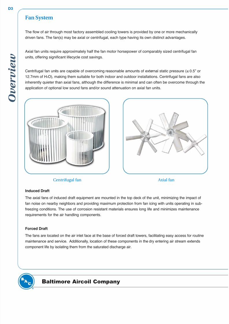
Fan System
The flow of air through most factory assembled cooling towers is provided by one or more mechanically
driven fans. The fan(s) may be axial or centrifugal, each type having its own distinct advantages.
Axial fan units require approximately half the fan motor horsepower of comparably sized centrifugal fan
units, offering significant lifecycle cost savings.
Centrifugal fan units are capable of overcoming reasonable amounts of external static pressure (≤ 0.5” or
12.7mm of H2O), making them suitable for both indoor and outdoor installations. Centrifugal fans are also
inherently quieter than axial fans, although the difference is minimal and can often be overcome through the
application of optional low sound fans and/or sound attenuation on axial fan units.
Induced Draft
The axial fans of induced draft equipment are mounted in the top deck of the unit, minimizing the impact of
fan noise on nearby neighbors and providing maximum protection from fan icing with units operating in sub-
freezing conditions. The use of corrosion resistant materials ensures long life and minimizes maintenance
requirements for the air handling components.
Forced Draft
The fans are located on the air inlet face at the base of forced draft towers, facilitating easy access for routine
maintenance and service. Additionally, location of these components in the dry entering air stream extends
component life by isolating them from the saturated discharge air.
Centrifugal fan Axial fan
8/3/2019 HBii2007 D01 OCT Overview
http://slidepdf.com/reader/full/hbii2007-d01-oct-overview 4/6
g
...because temperature matters™
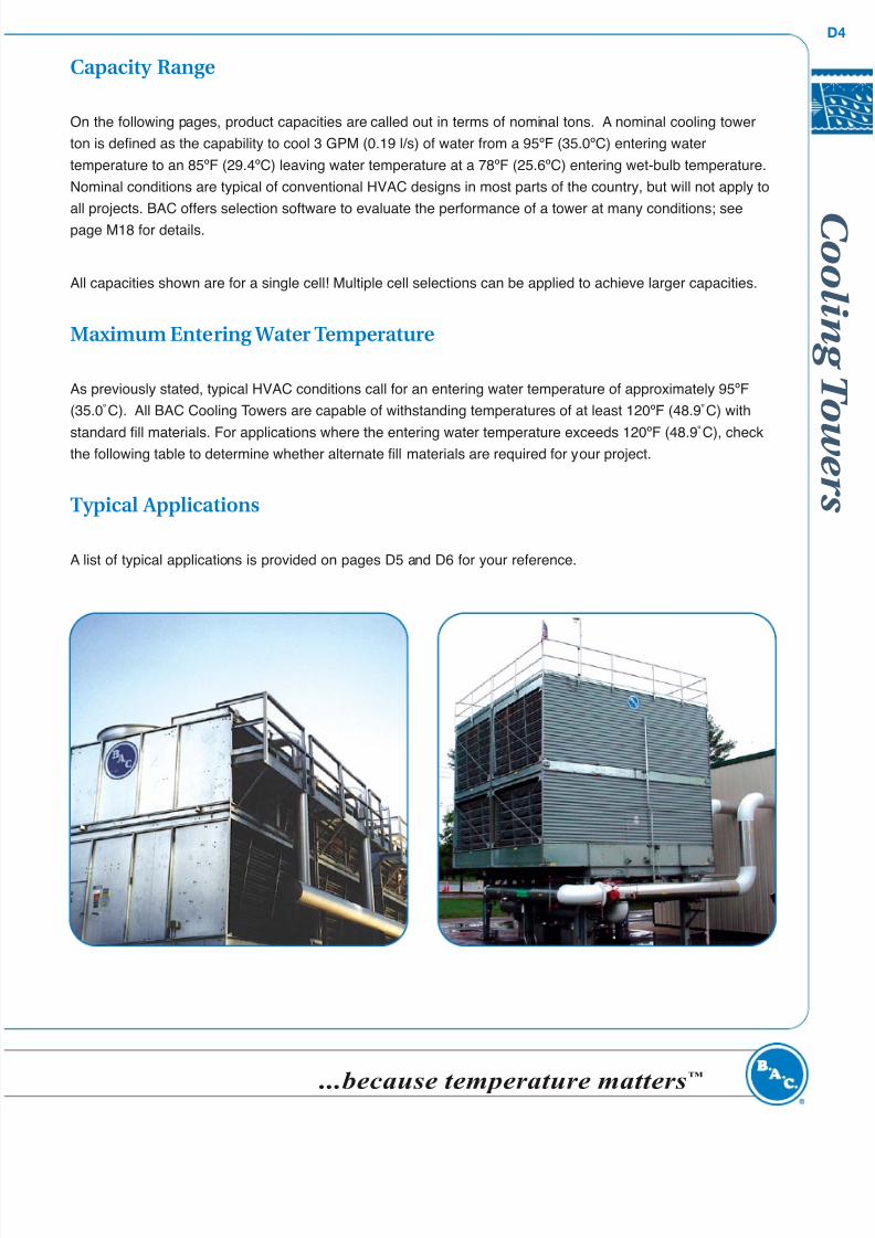
Capacity Range
On the following pages, product capacities are called out in terms of nominal tons. A nominal cooling tower
ton is defined as the capability to cool 3 GPM (0.19 l/s) of water from a 95ºF (35.0ºC) entering water
temperature to an 85ºF (29.4ºC) leaving water temperature at a 78ºF (25.6ºC) entering wet-bulb temperature.
Nominal conditions are typical of conventional HVAC designs in most parts of the country, but will not apply to
all projects. BAC offers selection software to evaluate the performance of a tower at many conditions; see
page M18 for details.
All capacities shown are for a single cell! Multiple cell selections can be applied to achieve larger capacities.
Maximum Entering Water Temperature
As previously stated, typical HVAC conditions call for an entering water temperature of approximately 95ºF
(35.0˚C). All BAC Cooling Towers are capable of withstanding temperatures of at least 120ºF (48.9˚C) with
standard fill materials. For applications where the entering water temperature exceeds 120ºF (48.9˚C), checkthe following table to determine whether alternate fill materials are required for your project.
Typical Applications
A list of typical applications is provided on pages D5 and D6 for your reference.
8/3/2019 HBii2007 D01 OCT Overview
http://slidepdf.com/reader/full/hbii2007-d01-oct-overview 5/6
O v e r v i e w
D5
Baltimore Aircoil Company
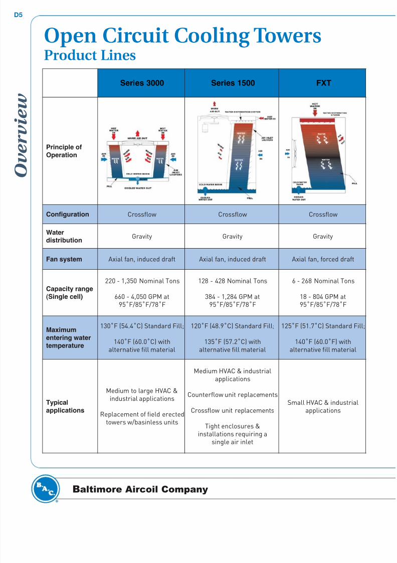
Open Circuit Cooling TowersProduct Lines
Series 3000 Series 1500 FXT
Principle of
Operation
Configuration Crossflow Crossflow Crossflow
Waterdistribution
Gravity Gravity Gravity
Fan system Axial fan, induced draft Axial fan, induced draft Axial fan, forced draft
Capacity range
(Single cell)
220 - 1,350 Nominal Tons
660 - 4,050 GPM at95˚F/85˚F/78˚F
128 - 428 Nominal Tons
384 - 1,284 GPM at95˚F/85˚F/78˚F
6 - 268 Nominal Tons
18 - 804 GPM at95˚F/85˚F/78˚F
Maximum
entering water
temperature
130˚F (54.4˚C) Standard Fill;
140˚F (60.0˚C) withalternative fill material
120˚F (48.9˚C) Standard Fill;
135˚F (57.2˚C) withalternative fill material
125˚F (51.7˚C) Standard Fill;
140˚F (60.0˚F) withalternative fill material
Typical
applications
Medium to large HVAC &industrial applications
Replacement of field erectedtowers w/basinless units
Medium HVAC & industrialapplications
Counterflow unit replacements
Crossflow unit replacements
Tight enclosures &installations requiring a
single air inlet
Small HVAC & industrialapplications
8/3/2019 HBii2007 D01 OCT Overview
http://slidepdf.com/reader/full/hbii2007-d01-oct-overview 6/6
g
...because temperature matters™
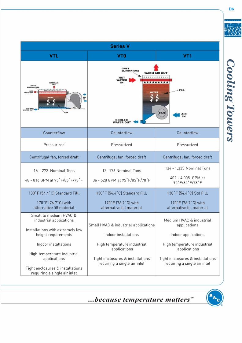
Series V
VTL VT0 VT1
Counterflow Counterflow Counterflow
Pressurized Pressurized Pressurized
Centrifugal fan, forced draft Centrifugal fan, forced draft Centrifugal fan, forced draft
16 - 272 Nominal Tons
48 - 816 GPM at 95˚F/85˚F/78˚F
12 -176 Nominal Tons
36 - 528 GPM at 95˚F/85˚F/78˚F
134 - 1,335 Nominal Tons
402 - 4,005 GPM at95˚F/85˚F/78˚F
130˚F (54.4˚C) Standard Fill;
170˚F (76.7˚C) withalternative fill material
130˚F (54.4˚C) Standard Fill;
170˚F (76.7˚C) withalternative fill material
130˚F (54.4˚C) Std Fill;
170˚F (76.7˚C) withalternative fill material
Small to medium HVAC &industrial applications
Installations with extremely lowheight requirements
Indoor installations
High temperature industrialapplications
Tight enclosures & installationsrequiring a single air inlet
Small HVAC & industrial applications
Indoor installations
High temperature industrialapplications
Tight enclosures & installationsrequiring a single air inlet
Medium HVAC & industrialapplications
Indoor applications
High temperature industrialapplications
Tight enclosures & installationsrequiring a single air inlet