Embed Size (px)
Citation preview

© Copyright 2012 Crescent Design, Inc.
Page 1
HBLT Pressure Manager
For
Win2000/XP
Operations Manual
Version 1.66
September 27, 2012
Revision: September 27, 2012
Crescent Design, Inc.
9932 Mesa Rim Road, Suite B
San Diego, California 92121-3930
(858) 452-3240
www.crescentdesign.com
© Copyright 2012 Crescent Design, Inc.
Page 2
TABLE OF CONTENTS
INTRODUCTION .............................................................................................................................. 6
INSTALLATION ................................................................................................................................ 6
OPERATION..................................................................................................................................... 7
PRESSURE PROFILE PANEL ................................................................................................................. 7 Panel Controls ............................................................................................................................... 7 Panel Indicators ............................................................................................................................ 7 Panel Buttons ................................................................................................................................ 8 Panel Menu ................................................................................................................................... 9
GRAPH SETTINGS PANEL .................................................................................................................. 10 Panel Controls ............................................................................................................................. 11 Panel Entry Controls ................................................................................................................... 11 Panel Buttons .............................................................................................................................. 12
LOGGING OPTIONS PANEL ................................................................................................................. 12 Panel Controls ............................................................................................................................. 13 Panel Entry Controls ................................................................................................................... 13 Panel Buttons .............................................................................................................................. 13
MICROMETER PANEL 1 ...................................................................................................................... 13 Panel Controls ............................................................................................................................. 14 Panel Entry Controls ................................................................................................................... 14 Panel Buttons .............................................................................................................................. 14
MICROMETER PANEL 2 ...................................................................................................................... 14 Panel Controls ............................................................................................................................. 15 Panel Entry Controls ................................................................................................................... 15 Panel Buttons .............................................................................................................................. 15
MICROMETER PANEL 3 ...................................................................................................................... 15 Panel Controls ............................................................................................................................. 15 Panel Buttons .............................................................................................................................. 15
TEST PARAMETERS PANEL ................................................................................................................ 15 Panel Controls ............................................................................................................................. 16 Panel Entry .................................................................................................................................. 16 Panel Indicators .......................................................................................................................... 16 Panel Buttons .............................................................................................................................. 19 Panel Indicators – Smart Manifold .............................................................................................. 20 Panel Menu ................................................................................................................................. 22
PASSWORD PANEL............................................................................................................................ 24 Panel Controls ............................................................................................................................. 24 Text Control ................................................................................................................................. 24 Panel Buttons .............................................................................................................................. 24
RENAME TEST PANEL ....................................................................................................................... 24 Panel Controls ............................................................................................................................. 25 Text Control ................................................................................................................................. 25 Panel Buttons .............................................................................................................................. 25
SCRIPT EDITOR PANEL ...................................................................................................................... 25 Panel Controls ............................................................................................................................. 26 Panel Entry Controls ................................................................................................................... 26 Script Commands ........................................................................................................................ 26 Panel Menu ................................................................................................................................. 32
NEW SCRIPT POPUP PANEL .............................................................................................................. 33 Panel Controls ............................................................................................................................. 33 Panel Buttons .............................................................................................................................. 33 Panel Entry .................................................................................................................................. 33
© Copyright 2012 Crescent Design, Inc.
Page 3
SCRIPT SELECT PANEL ..................................................................................................................... 33 Panel Controls ............................................................................................................................. 34 Panel Buttons .............................................................................................................................. 34 Panel Menu ................................................................................................................................. 35 Panel Indicator Controls .............................................................................................................. 35
LOG PANEL ....................................................................................................................................... 36 Panel Controls ............................................................................................................................. 36 Log Text Box ............................................................................................................................... 37 Panel Menu ................................................................................................................................. 37
REPORT PANEL ................................................................................................................................ 38 Panel Controls ............................................................................................................................. 39 Report Text Box .......................................................................................................................... 39 Panel Menu ................................................................................................................................. 39
MICROMETER PANEL ........................................................................................................................ 40 Panel Controls ............................................................................................................................. 40 Panel Menu ................................................................................................................................. 41
NEW TEST WIZARD PANEL – TEST GENERAL INFORMATION ............................................................... 41 Panel Controls ............................................................................................................................. 41 Panel Buttons .............................................................................................................................. 42 Panel Entry .................................................................................................................................. 42
NEW TEST WIZARD PANEL – PARAMETERS COMMON TO ALL TESTS ................................................... 42 Panel Controls ............................................................................................................................. 43 Panel Buttons .............................................................................................................................. 43 Panel Entry .................................................................................................................................. 43
NEW TEST WIZARD PANEL – LINEAR RAMP TEST PARAMETERS ......................................................... 44 Panel Controls ............................................................................................................................. 44 Panel Buttons .............................................................................................................................. 44 Panel Entry .................................................................................................................................. 44
NEW TEST WIZARD PANEL – STAIRCASE TEST PARAMETERS ............................................................. 45 Panel Controls ............................................................................................................................. 45 Panel Buttons .............................................................................................................................. 45 Panel Entry .................................................................................................................................. 45
NEW TEST WIZARD PANEL – FATIGUE TEST PARAMETERS ................................................................. 46 Panel Controls ............................................................................................................................. 46 Panel Buttons .............................................................................................................................. 46 Panel Entry .................................................................................................................................. 46
NEW TEST WIZARD PANEL – INCREMENT TEST PARAMETERS ............................................................ 47 Panel Controls ............................................................................................................................. 47 Panel Buttons .............................................................................................................................. 47 Panel Entry .................................................................................................................................. 47
NEW TEST WIZARD PANEL – CUSTOM TEST PARAMETERS ................................................................. 48 Panel Controls ............................................................................................................................. 48 Panel Buttons .............................................................................................................................. 48 Panel Entry .................................................................................................................................. 48
NEW TEST WIZARD PANEL – SMART MANIFOLD PARAMETERS ............................................................ 49 Panel Controls ............................................................................................................................. 49 Panel Buttons .............................................................................................................................. 49 Panel Entry .................................................................................................................................. 50
DELETE HBLT TESTS PANEL ............................................................................................................ 51 Panel Controls ............................................................................................................................. 51 Panel Buttons .............................................................................................................................. 52 Panel Indicator Control ................................................................................................................ 52
TEST RESULTS PANEL ...................................................................................................................... 52 Panel Controls ............................................................................................................................. 52 Panel Indicator Control ................................................................................................................ 52 Panel Menu ................................................................................................................................. 53
© Copyright 2012 Crescent Design, Inc.
Page 4
SUMMARY PANEL .............................................................................................................................. 54 Panel Controls ............................................................................................................................. 54 Panel Buttons .............................................................................................................................. 54 Panel Indicator Control ................................................................................................................ 54 Panel Menu ................................................................................................................................. 56
HBLT SETUP AND CABLING ....................................................................................................... 59
APPLICATIONS ............................................................................................................................. 61
CREATING A NEW TEST USING THE NEW BUTTON .............................................................................. 61 CREATING A NEW TEST USING THE NEW TEST WIZARD ..................................................................... 62 EDITING A TEST ................................................................................................................................ 63 DELETING A SINGLE TEST ................................................................................................................. 64 DELETING MULTIPLE TESTS .............................................................................................................. 64 SELECTING A TEST ........................................................................................................................... 64 CREATING A NEW SCRIPT ................................................................................................................. 65 EDITING A SCRIPT ............................................................................................................................. 66 SELECTING A SCRIPT ........................................................................................................................ 66 RUNNING THE SELECTED TEST OR SCRIPT ......................................................................................... 67 VIEWING AND PRINTING A REPORT .................................................................................................... 67 VIEWING AND PRINTING A REPORT – SMART MANIFOLD ...................................................................... 68 VIEWING AND PRINTING A LOG .......................................................................................................... 68 CAPTURING MICROMETER READINGS ................................................................................................ 68 VIEWING AND PRINTING A MICROMETER TABLE .................................................................................. 68
MESSAGES .................................................................................................................................... 70
LOG MACHINE STATE MESSAGES ...................................................................................................... 70 LOG INPUT LINE MESSAGE ................................................................................................................ 70 TEST DATA MESSAGE ....................................................................................................................... 71 TEST RESULTS MESSAGES ............................................................................................................... 71 LOG STATUS MESSAGES ................................................................................................................... 72 LOG ERROR MESSAGES .................................................................................................................... 74 LOW LEVEL ERROR MESSAGES ....................................................................................................... 113 POPUP WINDOW MESSAGES ........................................................................................................... 114
About Pressure Manager .......................................................................................................... 114 Delete Popup............................................................................................................................. 115 Delete Confirmation Popup ....................................................................................................... 115 Delete HBLT Tests Popup ........................................................................................................ 115 Delete Script Popup .................................................................................................................. 115 Safety Door Opened ................................................................................................................. 116 Print Error Popup ...................................................................................................................... 116 Replace Tests? Popup .............................................................................................................. 116 Replace Tests? Confirmation Popup ........................................................................................ 117 Save As Error Popup ................................................................................................................ 117 Save As Error Popup ................................................................................................................ 117 Save Data Popup ...................................................................................................................... 117 Save Error Popup ...................................................................................................................... 118 Save Log Popup ........................................................................................................................ 118 Save Report Popup ................................................................................................................... 118 Save Script Popup .................................................................................................................... 118 Script Save As Popup ............................................................................................................... 119 Security Popup 1 ....................................................................................................................... 119 Security Popup 2 ....................................................................................................................... 119 Security Popup 3 ....................................................................................................................... 120 Security Popup 4 ....................................................................................................................... 120 Smart Manifold .......................................................................................................................... 120
© Copyright 2012 Crescent Design, Inc.
Page 5
Warning – Duplicate Test Name Popup .................................................................................... 121 Warning – Existing File Popup .................................................................................................. 121 Warning – No HBLT found Popup ............................................................................................. 122 Warning – Maximum Tests Popup ............................................................................................ 123 Warning – No Test Name Popup .............................................................................................. 123 Warning – Run Test/Script First Popup..................................................................................... 124 Warning Test Popup ................................................................................................................. 124 Warning Micrometer Popup ...................................................................................................... 124 Warning Micrometer Popup ...................................................................................................... 124
APPENDIX A – HBLT PARAMETER MINIMUMS, MAXIMUMS, AND DEFAULTS ................... 125
25 PSI HBLT MODEL ..................................................................................................................... 126 100 PSI HBLT MODEL ................................................................................................................... 127 250 PSI HBLT MODEL ................................................................................................................... 128 500 PSI HBLT MODEL ................................................................................................................... 129 1000 PSI HBLT MODEL ................................................................................................................. 130 2000 PSI HBLT MODEL ................................................................................................................. 131 3000 PSI HBLT MODEL ................................................................................................................. 132 5000 PSI HBLT MODEL ................................................................................................................. 133
APPENDIX B – PRESSURE DATA FILE STRUCTURE ............................................................. 134
APPENDIX C – MICROMETER DATA FILE STRUCTURE ........................................................ 136
© Copyright 2012 Crescent Design, Inc.
Page 6
Introduction
HBLT Pressure Manager is a Windows based program that provides remote operation and data collection from a Hydraulic Burst Leak Tester (HBLT). Pressure Manager can execute either HBLT native tests or Pressure Manager scripts. Pressure Manager collects and displays current pressure, peak pressure and one of two volumetric data points at up to 1/100 second intervals. The operator may save the collected data as a comma delimited file for later display using Pressure Manager or for input to other data analysis programs.
Pressure Manager supports a HBLT with a Smart Manifold attached. Pressure Manager provides a Smart Manifold summary screen that displays summary information by channel during the test. There are test setup values and script commands to set the manifold options. When finished with a test or script, the operator may view, save, or print the data as a whole or by channel.
Installation
Crescent Design delivers the HBLT Pressure Manager software on a CD-ROM. The installation script checks for installed components and tailors the installation to the computer’s configuration. The script first installs the security drivers. The script then checks for and installs the laser micrometer components required for execution. Finally, the script installs the Pressure Manager program along with the necessary Lab Windows/CVI and NI-VISA components.
Follow these instructions to install the software:
1. If the security key is USB, unplug it from the system.
2. Insert the CR-ROM into the CD_ROM drive.
3. If your computer has autostart enabled, wait until the install script starts. If your computer does not have autostart enabled, navigate to the CD-ROM and double click on the PM_INSTALL program. This is the install script.
4. The script asks if you want to install the software. Answer Yes.
5. If you are not installing from a CD-ROM, the script may ask for the path to the installation directory. Enter the path and click OK.
6. When the Pressure Manager install script runs, keep clicking the next button until the script finishes. Use all the default settings.
7. When the Pressure Manager script finishes, there may be window requesting a system restart. Select the restart system button.
8. Your HBLT must be at least version 2.51 to operate correctly with Pressure Manager version 1.65. Connect the serial cable to the HBLT and the PC. Then double click the GO.BAT file located in this directory. On the HBLT, select the Download New Program function under the Engineering menu. Wait until the download completes. Or, use the DLDF2 to download the HBLT software. See the DLDF2 documentation for instructions.
9. Store the CD-ROM in secure place.
10. Finally, install the Rainbow Sentinel-Pro software key on the PC printer port. The key is transparent to the printer. If the security key is a USB key, plug it into a USB port.
© Copyright 2012 Crescent Design, Inc.
Page 7
Operation
This manual describes the operation of Pressure Manager by describing the elements of each program panel. After a general panel function description, the manual lists and describes each control, indicator and menu item the operator may use.
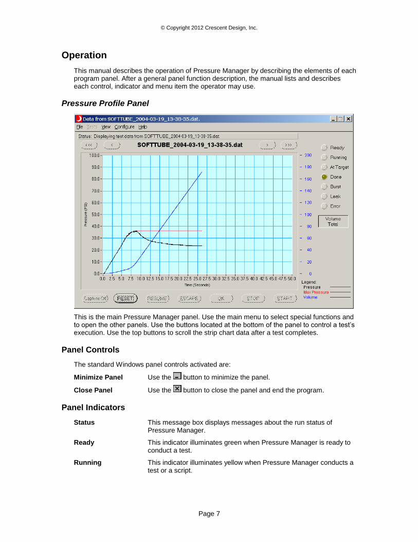
Pressure Profile Panel
This is the main Pressure Manager panel. Use the main menu to select special functions and to open the other panels. Use the buttons located at the bottom of the panel to control a test’s execution. Use the top buttons to scroll the strip chart data after a test completes.
Panel Controls
The standard Windows panel controls activated are:
Minimize Panel Use the button to minimize the panel.
Close Panel Use the button to close the panel and end the program.
Panel Indicators
Status This message box displays messages about the run status of Pressure Manager.
Ready This indicator illuminates green when Pressure Manager is ready to conduct a test.
Running This indicator illuminates yellow when Pressure Manager conducts a test or a script.
© Copyright 2012 Crescent Design, Inc.
Page 8
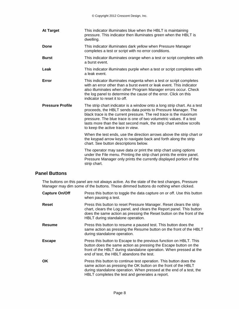
At Target This indicator illuminates blue when the HBLT is maintaining pressure. This indicator then illuminates green when the HBLT is dwelling.
Done This indicator illuminates dark yellow when Pressure Manager completes a test or script with no error conditions.
Burst This indicator illuminates orange when a test or script completes with a burst event.
Leak This indicator illuminates purple when a test or script completes with a leak event.
Error This indicator illuminates magenta when a test or script completes with an error other than a burst event or leak event. This indicator also illuminates when other Program Manager errors occur. Check the log panel to determine the cause of the error. Click on this indicator to reset it to off.
Pressure Profile The strip chart indicator is a window onto a long strip chart. As a test proceeds, the HBLT sends data points to Pressure Manager. The black trace is the current pressure. The red trace is the maximum pressure. The blue trace is one of two volumetric values. If a test lasts more than the last second mark, the strip chart window scrolls to keep the active trace in view.
When the test ends, use the direction arrows above the strip chart or the keypad arrow keys to navigate back and forth along the strip chart. See button descriptions below.
The operator may save data or print the strip chart using options under the File menu. Printing the strip chart prints the entire panel. Pressure Manager only prints the currently displayed portion of the strip chart.
Panel Buttons
The buttons on this panel are not always active. As the state of the test changes, Pressure Manager may dim some of the buttons. These dimmed buttons do nothing when clicked.
Capture On/Off Press this button to toggle the data capture on or off. Use this button when pausing a test.
Reset Press this button to reset Pressure Manager. Reset clears the strip chart, clears the Log panel, and clears the Report panel. This button does the same action as pressing the Reset button on the front of the HBLT during standalone operation.
Resume Press this button to resume a paused test. This button does the same action as pressing the Resume button on the front of the HBLT during standalone operation.
Escape Press this button to Escape to the previous function on HBLT. This button does the same action as pressing the Escape button on the front of the HBLT during standalone operation. When pressed at the end of test, the HBLT abandons the test.
OK Press this button to continue test operation. This button does the same action as pressing the OK button on the front of the HBLT during standalone operation. When pressed at the end of a test, the HBLT completes the test and generates a report.
© Copyright 2012 Crescent Design, Inc.
Page 9
Stop Press this button to stop test operation. This button does the same action as pressing the Stop button on the front of the HBLT during standalone operation.
Start Press this button to start test operation. This button does the same action as pressing the Start button on the front of the HBLT during standalone operation.
<< This button shifts the strip chart window to the left one full screen or to the beginning of the strip chart. The down arrow key performs the same function as this button.
< This button shifts the strip chart window to the left one increment. The left arrow key performs the same function as this button.
>> This button shifts the strip chart window to the right one full screen or to the end of the strip chart. The up arrow key performs the same function as this button.
> This button shifts the strip chart window to the right one increment. The right arrow key performs the same function as this button.
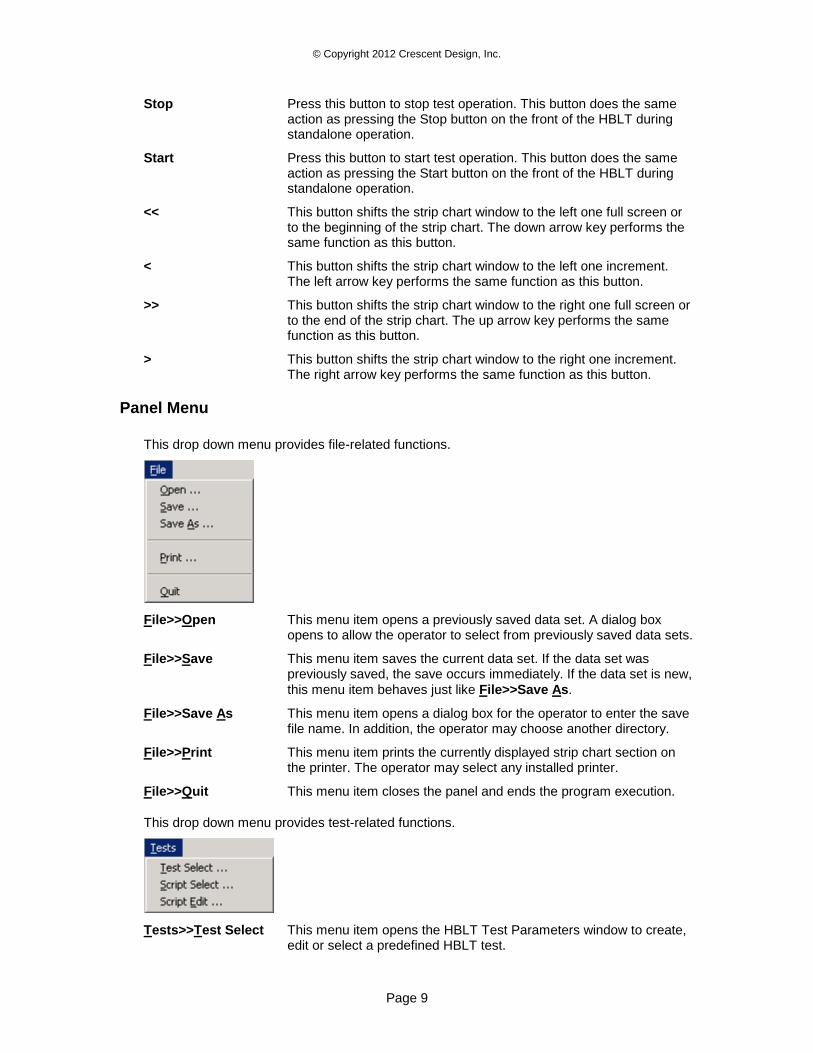
Panel Menu
This drop down menu provides file-related functions.
File>>Open This menu item opens a previously saved data set. A dialog box opens to allow the operator to select from previously saved data sets.
File>>Save This menu item saves the current data set. If the data set was previously saved, the save occurs immediately. If the data set is new,
this menu item behaves just like File>>Save As.
File>>Save As This menu item opens a dialog box for the operator to enter the save file name. In addition, the operator may choose another directory.
File>>Print This menu item prints the currently displayed strip chart section on the printer. The operator may select any installed printer.
File>>Quit This menu item closes the panel and ends the program execution.
This drop down menu provides test-related functions.
Tests>>Test Select This menu item opens the HBLT Test Parameters window to create, edit or select a predefined HBLT test.
© Copyright 2012 Crescent Design, Inc.
Page 10
Tests>>Script Select This menu item opens the Pressure Manager Script Select panel to select a predefined script.
Tests>>Script Edit This menu item opens the Pressure Manager Script Edit panel to create a new script or edit an exiting script.
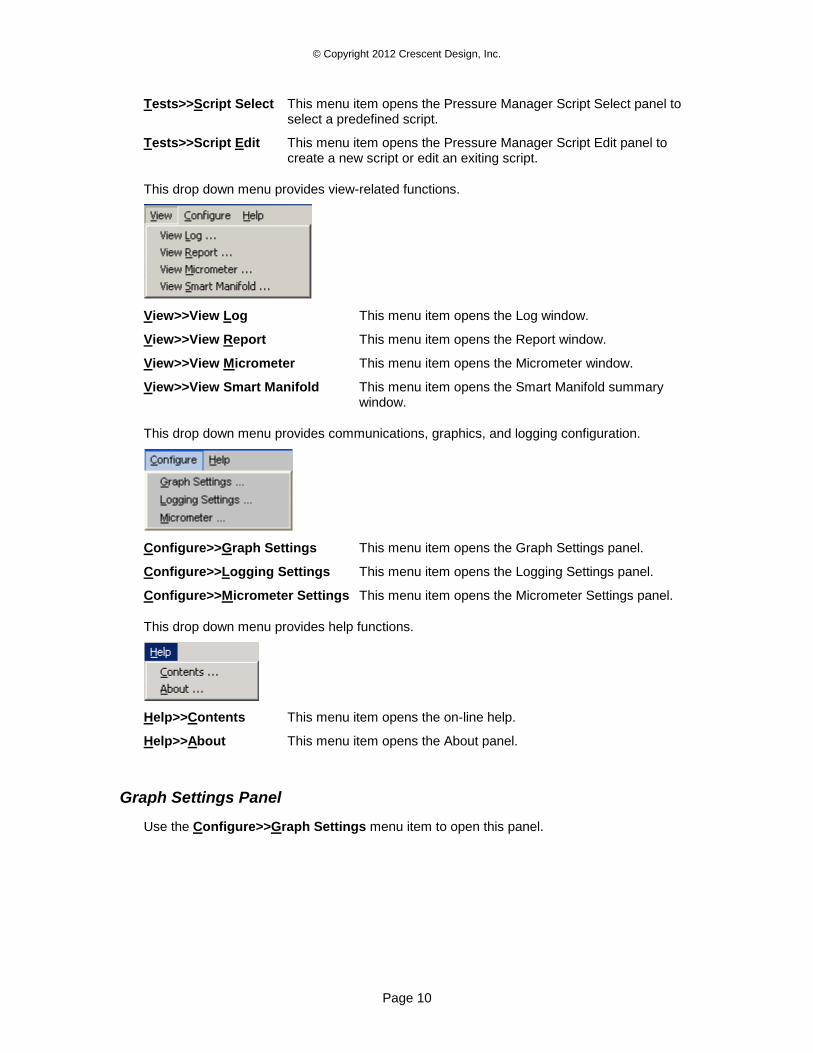
This drop down menu provides view-related functions.
View>>View Log This menu item opens the Log window.
View>>View Report This menu item opens the Report window.
View>>View Micrometer This menu item opens the Micrometer window.
View>>View Smart Manifold This menu item opens the Smart Manifold summary window.
This drop down menu provides communications, graphics, and logging configuration.
Configure>>Graph Settings This menu item opens the Graph Settings panel.
Configure>>Logging Settings This menu item opens the Logging Settings panel.
Configure>>Micrometer Settings This menu item opens the Micrometer Settings panel.
This drop down menu provides help functions.
Help>>Contents This menu item opens the on-line help.
Help>>About This menu item opens the About panel.
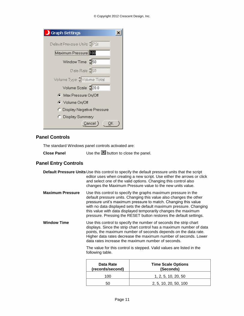
Graph Settings Panel
Use the Configure>>Graph Settings menu item to open this panel.
© Copyright 2012 Crescent Design, Inc.
Page 11
Panel Controls
The standard Windows panel controls activated are:
Close Panel Use the button to close the panel.
Panel Entry Controls
Default Pressure Units Use this control to specify the default pressure units that the script editor uses when creating a new script. Use either the arrows or click and select one of the valid options. Changing this control also changes the Maximum Pressure value to the new units value.
Maximum Pressure Use this control to specify the graphs maximum pressure in the default pressure units. Changing this value also changes the other pressure unit’s maximum pressure to match. Changing this value with no data displayed sets the default maximum pressure. Changing this value with data displayed temporarily changes the maximum pressure. Pressing the RESET button restores the default settings.
Window Time Use this control to specify the number of seconds the strip chart displays. Since the strip chart control has a maximum number of data points, the maximum number of seconds depends on the data rate. Higher data rates decrease the maximum number of seconds. Lower data rates increase the maximum number of seconds.
The value for this control is stepped. Valid values are listed in the following table.
Data Rate
(records/second)
Time Scale Options
(Seconds)
100 1, 2, 5, 10, 20, 50
50 2, 5, 10, 20, 50, 100
© Copyright 2012 Crescent Design, Inc.
Page 12
20 5, 10, 20, 50, 100, 200
10 10, 20, 50, 100, 200, 500
5 20, 50, 100, 200, 500
2 50, 100, 200, 500
1 100, 200, 500
Data Rate Use this control to specify the data rate sent from the HBLT. This is not the serial baud rate. It is the rate the HBLT uses to send pressure information packets. Use either the arrows or click and select one of the valid options. Choices are 1, 2, 5, 10, 20, 50 or 100 pressure packets per second.
Volume Type Use this control to specify the volume type the HBLT sends with a pressure packet. Use either the arrows or click and select one of the valid options.
The valid options are: Volume Total Volume Increment No Volume
Volume Scale (%) Use this control to specify the number of cc's per graph unit. The possible choices are: 0.1, 0.2, 0.5, 1.0, 2.0, 5.0, 10.0, 20.0, 50.0, 100.0.
Max Pressure On/Off Use this control to enable or disable the display of the maximum pressure trace (red line) on the strip chart.
Volume On/Off Use this control to enable or disable the display of the volume data trace (blue line) on the strip chart.
Display Negative Pressure Use this control to select between displaying the graph allowing for negative pressure and not allowing for negative pressure.
Display Summary Use this control to enable or disable displaying the summary panel. The summary panel displays the event pressure, peak pressure and time into last state. Also, the summary panel displays the messages for this test.
Panel Buttons
Cancel Use this button to close the Graph Settings panel without any changes.
OK Use this button to close the Graph Settings panel with all changes.
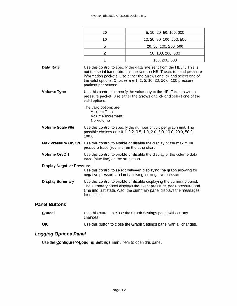
Logging Options Panel
Use the Configure>>Logging Settings menu item to open this panel.
© Copyright 2012 Crescent Design, Inc.
Page 13
Panel Controls
The standard Windows panel controls activated are:
Close Panel Use the button to close the panel.
Panel Entry Controls
Default Logging Directory Use this control to set the default directory for logging all five-log items. To select a directory, double click on the control. This opens the select directory dialog box. This dialog box allows the operator to select an existing directory or select a new directory.
Data Logging Mode Use this control to set the mode for graph data logging. Select Always, Never, or Ask.
Report Logging Mode Use this control to set the mode for graph report logging. Select Always, Never, or Ask.
Log Logging Mode Use this control to set the mode for graph log logging. Select Always, Never, or Ask.
Micrometer Logging Mode Use this control to set the mode for micrometer report logging. Select Always, Never, or Ask.
Summary Logging Mode Use this control to set the mode for summary report logging. The summary may be the normal results panel or the Smart Manifold results panel. Select Always, Never, or Ask.
Panel Buttons
Browse Use this button to open the Select New Directory panel and select a new logging directory.
Cancel Use this button to close the Logging Options panel without any changes.
OK Use this button to close the Logging Options panel with all changes.
Micrometer Panel 1
Use the Configure>>Configure Micrometer menu item to open this panel from the main panel.
© Copyright 2012 Crescent Design, Inc.
Page 14
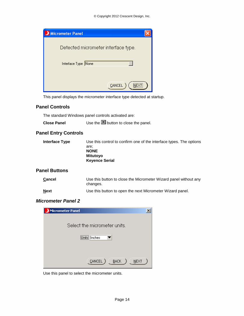
This panel displays the micrometer interface type detected at startup.
Panel Controls
The standard Windows panel controls activated are:
Close Panel Use the button to close the panel.
Panel Entry Controls
Interface Type Use this control to confirm one of the interface types. The options are;
NONE
Mitutoyo
Keyence Serial
Panel Buttons
Cancel Use this button to close the Micrometer Wizard panel without any changes.
Next Use this button to open the next Micrometer Wizard panel.
Micrometer Panel 2
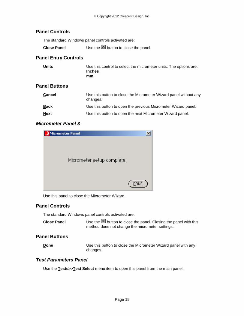
Use this panel to select the micrometer units.
© Copyright 2012 Crescent Design, Inc.
Page 15
Panel Controls
The standard Windows panel controls activated are:
Close Panel Use the button to close the panel.
Panel Entry Controls
Units Use this control to select the micrometer units. The options are:
Inches
mm.
Panel Buttons
Cancel Use this button to close the Micrometer Wizard panel without any changes.
Back Use this button to open the previous Micrometer Wizard panel.
Next Use this button to open the next Micrometer Wizard panel.
Micrometer Panel 3
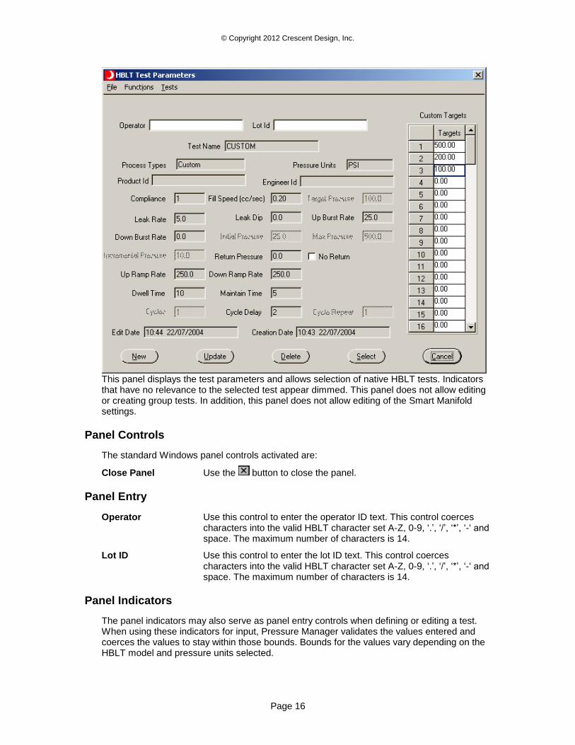
Use this panel to close the Micrometer Wizard.
Panel Controls
The standard Windows panel controls activated are:
Close Panel Use the button to close the panel. Closing the panel with this method does not change the micrometer settings.
Panel Buttons
Done Use this button to close the Micrometer Wizard panel with any changes.
Test Parameters Panel
Use the Tests>>Test Select menu item to open this panel from the main panel.
© Copyright 2012 Crescent Design, Inc.
Page 16
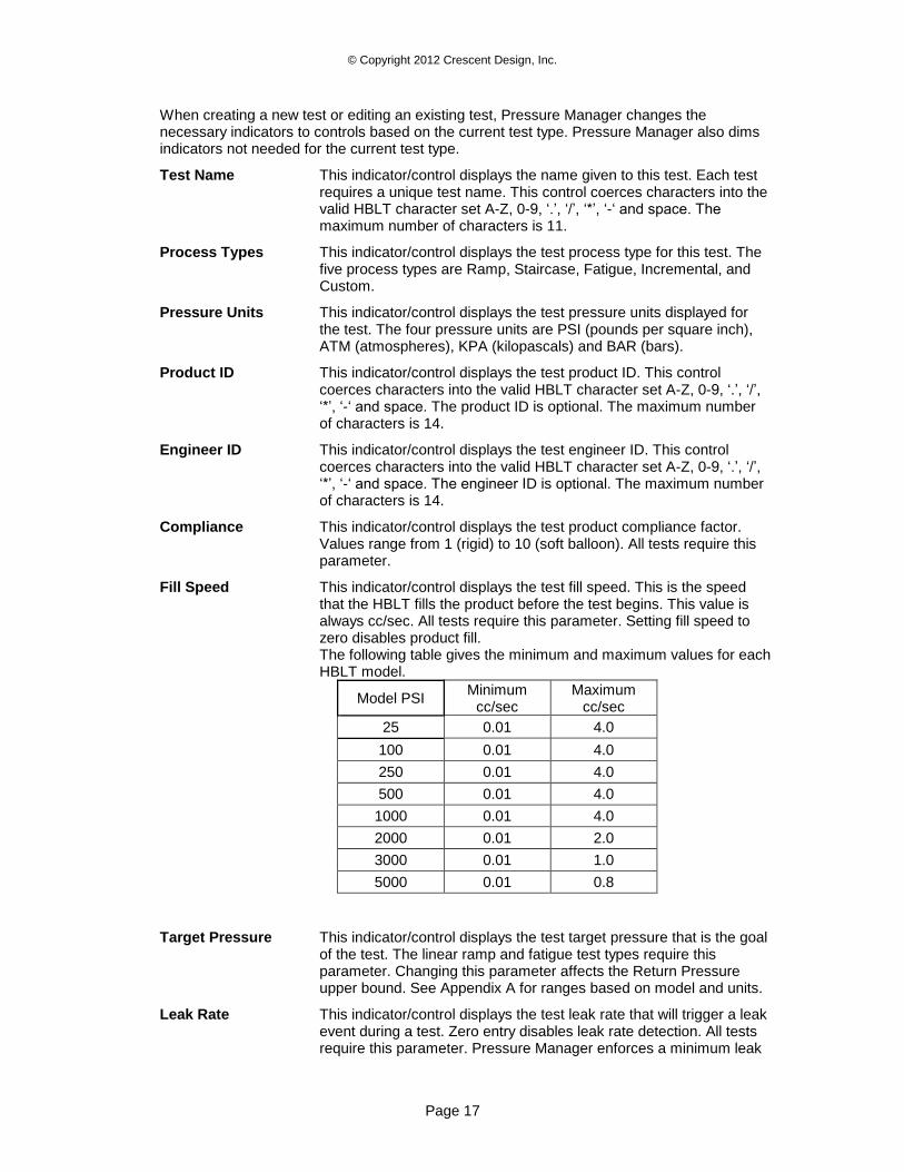
This panel displays the test parameters and allows selection of native HBLT tests. Indicators that have no relevance to the selected test appear dimmed. This panel does not allow editing or creating group tests. In addition, this panel does not allow editing of the Smart Manifold settings.
Panel Controls
The standard Windows panel controls activated are:
Close Panel Use the button to close the panel.
Panel Entry
Operator Use this control to enter the operator ID text. This control coerces characters into the valid HBLT character set A-Z, 0-9, ‘.’, ‘/’, ‘*’, ‘-‘ and space. The maximum number of characters is 14.
Lot ID Use this control to enter the lot ID text. This control coerces characters into the valid HBLT character set A-Z, 0-9, ‘.’, ‘/’, ‘*’, ‘-‘ and space. The maximum number of characters is 14.
Panel Indicators
The panel indicators may also serve as panel entry controls when defining or editing a test. When using these indicators for input, Pressure Manager validates the values entered and coerces the values to stay within those bounds. Bounds for the values vary depending on the HBLT model and pressure units selected.
© Copyright 2012 Crescent Design, Inc.
Page 17
When creating a new test or editing an existing test, Pressure Manager changes the necessary indicators to controls based on the current test type. Pressure Manager also dims indicators not needed for the current test type.
Test Name This indicator/control displays the name given to this test. Each test requires a unique test name. This control coerces characters into the valid HBLT character set A-Z, 0-9, ‘.’, ‘/’, ‘*’, ‘-‘ and space. The maximum number of characters is 11.
Process Types This indicator/control displays the test process type for this test. The five process types are Ramp, Staircase, Fatigue, Incremental, and Custom.
Pressure Units This indicator/control displays the test pressure units displayed for the test. The four pressure units are PSI (pounds per square inch), ATM (atmospheres), KPA (kilopascals) and BAR (bars).
Product ID This indicator/control displays the test product ID. This control coerces characters into the valid HBLT character set A-Z, 0-9, ‘.’, ‘/’, ‘*’, ‘-‘ and space. The product ID is optional. The maximum number of characters is 14.
Engineer ID This indicator/control displays the test engineer ID. This control coerces characters into the valid HBLT character set A-Z, 0-9, ‘.’, ‘/’, ‘*’, ‘-‘ and space. The engineer ID is optional. The maximum number of characters is 14.
Compliance This indicator/control displays the test product compliance factor. Values range from 1 (rigid) to 10 (soft balloon). All tests require this parameter.
Fill Speed This indicator/control displays the test fill speed. This is the speed that the HBLT fills the product before the test begins. This value is always cc/sec. All tests require this parameter. Setting fill speed to zero disables product fill. The following table gives the minimum and maximum values for each HBLT model.
Model PSI Minimum
cc/sec Maximum
cc/sec
25 0.01 4.0
100 0.01 4.0
250 0.01 4.0
500 0.01 4.0
1000 0.01 4.0
2000 0.01 2.0
3000 0.01 1.0
5000 0.01 0.8
Target Pressure This indicator/control displays the test target pressure that is the goal of the test. The linear ramp and fatigue test types require this parameter. Changing this parameter affects the Return Pressure upper bound. See Appendix A for ranges based on model and units.
Leak Rate This indicator/control displays the test leak rate that will trigger a leak event during a test. Zero entry disables leak rate detection. All tests require this parameter. Pressure Manager enforces a minimum leak
© Copyright 2012 Crescent Design, Inc.
Page 18
span of 15 PSI between the Up Burst Rate value and the Leak rate value. See Appendix A for ranges based on model and units.
Leak Dip This indicator/control displays the test leak dip that will trigger a leak dip event during a test. Zero entry disables leak dip detection. All tests require this parameter. See Appendix A for ranges based on model and units.
Up Burst Rate This indicator/control displays the test drop pressure rate that will trigger an up burst event during a test while ramping up. All tests require this parameter. Pressure Manager enforces a minimum leak span of 15 PSI between the Up Burst Rate value and the Leak rate value. See Appendix A for ranges based on model and units.
Down Burst Rate This indicator/control displays the test drop pressure rate that will trigger a down burst event during a test while ramping down. A zero entry disables down burst detection. To prevent false burst reporting, insure that the down burst rate exceeds the down ramp rate. Pressure Manager enforces a minimum leak span of 15 PSI between the Up Burst Rate value and the Leak rate value. All tests require this parameter. See Appendix A for ranges based on model and units.
Initial Pressure This indicator/control displays the test initial pressure to begin the test. The staircase and incremental test types require this parameter. Changing this parameter affects the Return Pressure upper bound. The Max Pressure caps the Initial Pressure. See Appendix A for ranges based on model and units.
Max Pressure This indicator/control displays the test maximum pressure that the test achieves. The staircase and incremental test types require this parameter. Max Pressure caps the Initial Pressure. Changing the Max Pressure below the Initial Pressure coerces the Initial Pressure below the Max Pressure. See Appendix A for ranges based on model and units.
Incremental Pressure This indicator/control displays the test pressure increment. The staircase and incremental test types require this parameter. See Appendix A for ranges based on model and units.
Return Pressure This indicator/control displays the test return pressure used during fatigue, incremental, and custom tests. The fatigue, incremental and custom test types require this parameter. For Fatigue tests, the upper bound is the Target Pressure-1. For Incremental tests, the upper bound is the Initial Pressure-1. For Custom tests, the upper bound is the Maximum Pressure-1. Pressure Manager grays this control if the No Return control is checked. See Appendix A for ranges based on model and units.
Up Ramp Rate This indicator/control displays the test up ramp rate. All tests require this parameter. See Appendix A for ranges based on model and units.
Down Ramp Rate This indicator/control displays the test down ramp rate. To prevent false burst reporting, insure the down ramp rate is less than the down burst rate. All tests require this parameter. See Appendix A for ranges based on model and units.
Dwell Time This indicator/control displays the test dwell time. All tests require this parameter. This parameter ranges from 1 to 999.
© Copyright 2012 Crescent Design, Inc.
Page 19
Maintain Time This indicator/control displays the test maintain time. All tests require this parameter. This parameter ranges from 1 to 999. However, it must always be less than or equal to the Dwell Time parameter.
Cycles This indicator/control displays the test cycle count. The fatigue test type requires this parameter. This parameter ranges from 1 to 9999.
Cycle Delay This indicator/control displays the test cycle delay. The incremental, fatigue, and custom test types require this parameter. This parameter ranges from 1 to 99. Pressure Manager grays this control if the No Return control is checked.
Cycle Repeat This indicator/control displays the test cycle repeat count. The incremental test type requires this parameter. This parameter ranges from 1 to 999.
Custom Targets This indicator/control displays the list of custom pressure targets. There are 100 possible targets. Double click on a cell to edit the cell content when the test is custom. If the No Return control is not checked, the values range from the minimum to maximum pressure targets. If the No Return control is checked, the minimum pressure is the same as the minimum return pressure. See Appendix A for ranges based on model and units.
No Return Check this control to disable the return pressure on custom tests. Clicking the control grays the Return Pressure and Cycle Delay controls. Also, the Custom Targets minimum value changes. When checked or unchecked, Pressure Manager forces the Custom Targets within the correct minimum.
Edit Date This indicator displays the test last-edit date.
Creation Date This indicator displays the test creation date.
Panel Buttons
Pressure Manager dims these buttons when they have no valid function.
New Press this button to define a new test. If the HBLT is password protected, select the Password menu item and enter the same password before using this function.
When pressed, the title of this button changes to NEXT. Successive clicks on this button walk the user through the test creation steps. This guarantees that the user enters the test parameters in the correct order. Most test parameters require the test type and test units be set first to control parameter entry.
After updating or canceling the test creation, Pressure Manager resets the title of this button to New.
Use the Cancel button to abandon a new test.
Select Press this button to select a test for execution and close this panel.
Update Press this button to edit and save a test. If the HBLT is password protected, select the Password menu item and enter the same password before using this function.
When pressed, the title of this button changes to SAVE. After editing the desired parameters, click this button again to send the changes to the HBLT.
© Copyright 2012 Crescent Design, Inc.
Page 20
Use the Cancel button to abandon an update test.
Delete Press this button to delete a test from the HBLT. If the HBLT is password protected, select the Password menu item and enter the same password before using this function.
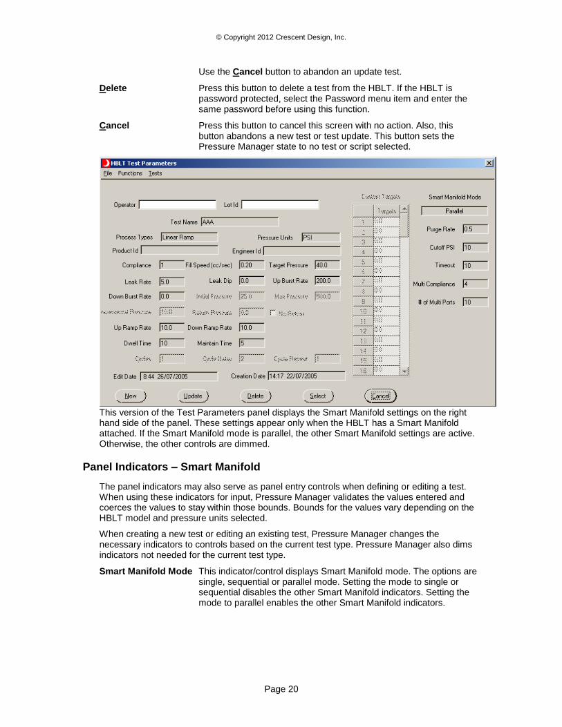
Cancel Press this button to cancel this screen with no action. Also, this button abandons a new test or test update. This button sets the Pressure Manager state to no test or script selected.
This version of the Test Parameters panel displays the Smart Manifold settings on the right hand side of the panel. These settings appear only when the HBLT has a Smart Manifold attached. If the Smart Manifold mode is parallel, the other Smart Manifold settings are active. Otherwise, the other controls are dimmed.
Panel Indicators – Smart Manifold
The panel indicators may also serve as panel entry controls when defining or editing a test. When using these indicators for input, Pressure Manager validates the values entered and coerces the values to stay within those bounds. Bounds for the values vary depending on the HBLT model and pressure units selected.
When creating a new test or editing an existing test, Pressure Manager changes the necessary indicators to controls based on the current test type. Pressure Manager also dims indicators not needed for the current test type.
Smart Manifold Mode This indicator/control displays Smart Manifold mode. The options are single, sequential or parallel mode. Setting the mode to single or sequential disables the other Smart Manifold indicators. Setting the mode to parallel enables the other Smart Manifold indicators.
© Copyright 2012 Crescent Design, Inc.
Page 21
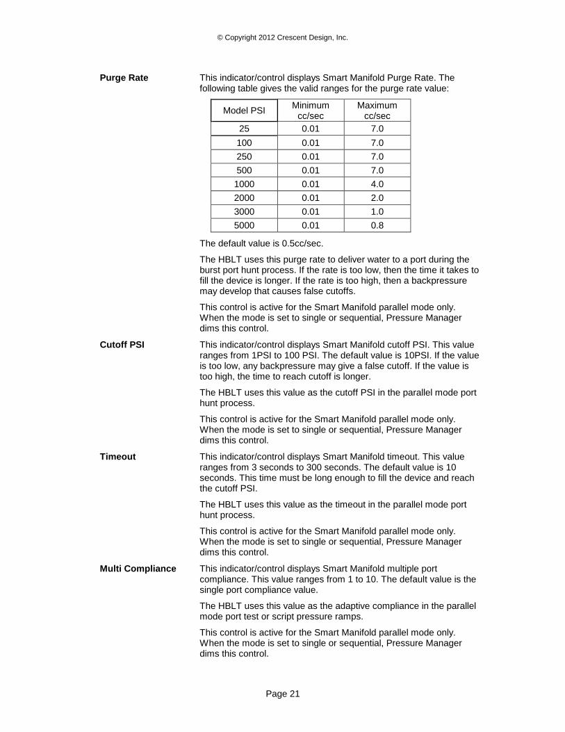
Purge Rate This indicator/control displays Smart Manifold Purge Rate. The following table gives the valid ranges for the purge rate value:
Model PSI Minimum
cc/sec Maximum
cc/sec
25 0.01 7.0
100 0.01 7.0
250 0.01 7.0
500 0.01 7.0
1000 0.01 4.0
2000 0.01 2.0
3000 0.01 1.0
5000 0.01 0.8
The default value is 0.5cc/sec.
The HBLT uses this purge rate to deliver water to a port during the burst port hunt process. If the rate is too low, then the time it takes to fill the device is longer. If the rate is too high, then a backpressure may develop that causes false cutoffs.
This control is active for the Smart Manifold parallel mode only. When the mode is set to single or sequential, Pressure Manager dims this control.
Cutoff PSI This indicator/control displays Smart Manifold cutoff PSI. This value ranges from 1PSI to 100 PSI. The default value is 10PSI. If the value is too low, any backpressure may give a false cutoff. If the value is too high, the time to reach cutoff is longer.
The HBLT uses this value as the cutoff PSI in the parallel mode port hunt process.
This control is active for the Smart Manifold parallel mode only. When the mode is set to single or sequential, Pressure Manager dims this control.
Timeout This indicator/control displays Smart Manifold timeout. This value ranges from 3 seconds to 300 seconds. The default value is 10 seconds. This time must be long enough to fill the device and reach the cutoff PSI.
The HBLT uses this value as the timeout in the parallel mode port hunt process.
This control is active for the Smart Manifold parallel mode only. When the mode is set to single or sequential, Pressure Manager dims this control.
Multi Compliance This indicator/control displays Smart Manifold multiple port compliance. This value ranges from 1 to 10. The default value is the single port compliance value.
The HBLT uses this value as the adaptive compliance in the parallel mode port test or script pressure ramps.
This control is active for the Smart Manifold parallel mode only. When the mode is set to single or sequential, Pressure Manager dims this control.
© Copyright 2012 Crescent Design, Inc.
Page 22
# of Multi Ports This indicator/control displays Smart Manifold multiple port count. This value ranges from 1 to 10. The default value is one.
The HBLT uses this value as the adaptive compliance port count in the parallel mode port test or script pressure ramps.
This control is active for the Smart Manifold parallel mode only. When the mode is set to single or sequential, Pressure Manager dims this control.
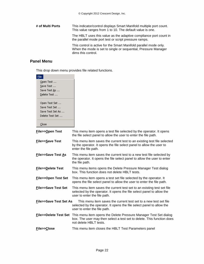
Panel Menu
This drop down menu provides file related functions.
File>>Open Test This menu item opens a test file selected by the operator. It opens the file select panel to allow the user to enter the file path.
File>>Save Test This menu item saves the current test to an existing test file selected by the operator. It opens the file select panel to allow the user to enter the file path.
File>>Save Test As This menu item saves the current test to a new test file selected by the operator. It opens the file select panel to allow the user to enter the file path.
File>>Delete Test This menu items opens the Delete Pressure Manager Test dialog box. This function does not delete HBLT tests.
File>>Open Test Set This menu item opens a test set file selected by the operator. It opens the file select panel to allow the user to enter the file path.
File>>Save Test Set This menu item saves the current test set to an existing test set file selected by the operator. It opens the file select panel to allow the user to enter the file path.
File>>Save Test Set As This menu item saves the current test set to a new test set file selected by the operator. It opens the file select panel to allow the user to enter the file path.
File>>Delete Test Set This menu item opens the Delete Pressure Manager Test Set dialog box. The user may then select a test set to delete. This function does not delete HBLT tests.
File>>Close This menu item closes the HBLT Test Parameters panel
© Copyright 2012 Crescent Design, Inc.
Page 23
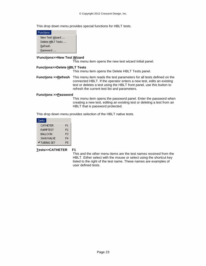
This drop down menu provides special functions for HBLT tests.
\Functions>>New Test Wizard This menu item opens the new test wizard initial panel.
Functions>>Delete HBLT Tests This menu item opens the Delete HBLT Tests panel.
Functions >>Refresh This menu item reads the test parameters for all tests defined on the connected HBLT. If the operator enters a new test, edits an existing test or deletes a test using the HBLT front panel, use this button to refresh the current test list and parameters.
Functions >>Password This menu item opens the password panel. Enter the password when creating a new test, editing an existing test or deleting a test from an HBLT that is password protected.
This drop down menu provides selection of the HBLT native tests.
Tests>>CATHETER F1 This and the other menu items are the test names received from the HBLT. Either select with the mouse or select using the shortcut key listed to the right of the test name. These names are examples of user defined tests.
© Copyright 2012 Crescent Design, Inc.
Page 24
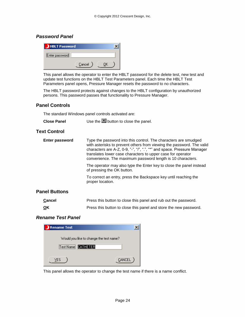
Password Panel
This panel allows the operator to enter the HBLT password for the delete test, new test and update test functions on the HBLT Test Parameters panel. Each time the HBLT Test Parameters panel opens, Pressure Manager resets the password to no characters.
The HBLT password protects against changes to the HBLT configuration by unauthorized persons. This password passes that functionality to Pressure Manager.
Panel Controls
The standard Windows panel controls activated are:
Close Panel Use the button to close the panel.
Text Control
Enter password Type the password into this control. The characters are smudged with asterisks to prevent others from viewing the password. The valid characters are A-Z, 0-9, ”-”, “/”, “.”, “*” and space. Pressure Manager translates lower case characters to upper case for operator convenience. The maximum password length is 10 characters.
The operator may also type the Enter key to close the panel instead of pressing the OK button.
To correct an entry, press the Backspace key until reaching the proper location.
Panel Buttons
Cancel Press this button to close this panel and rub out the password.
OK Press this button to close this panel and store the new password.
Rename Test Panel
This panel allows the operator to change the test name if there is a name conflict.
© Copyright 2012 Crescent Design, Inc.
Page 25
Panel Controls
The standard Windows panel controls activated are:
Close Panel Use the button to close the panel.
Text Control
Test Name This indicator/control displays the name given to this test. Each test requires a unique test name. This control coerces characters into the valid HBLT character set A-Z, 0-9, ‘.’, ‘/’, ‘*’, ‘-‘ and space. The maximum number of characters is 11.
Panel Buttons
Cancel Press this button to close this panel and cancels the function that caused the name conflict.
YES Press this button to close this panel and resubmit the function that caused the name conflict.
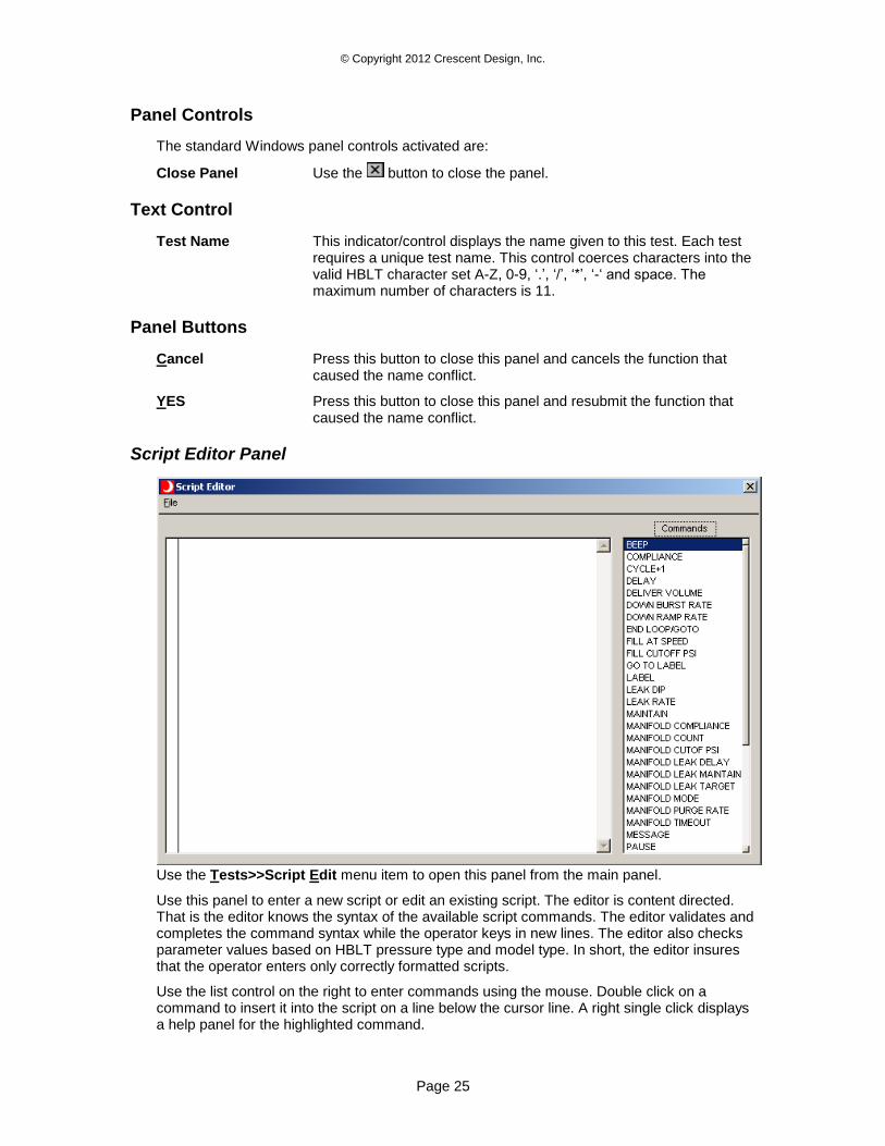
Script Editor Panel
Use the Tests>>Script Edit menu item to open this panel from the main panel.
Use this panel to enter a new script or edit an existing script. The editor is content directed. That is the editor knows the syntax of the available script commands. The editor validates and completes the command syntax while the operator keys in new lines. The editor also checks parameter values based on HBLT pressure type and model type. In short, the editor insures that the operator enters only correctly formatted scripts.
Use the list control on the right to enter commands using the mouse. Double click on a command to insert it into the script on a line below the cursor line. A right single click displays a help panel for the highlighted command.
© Copyright 2012 Crescent Design, Inc.
Page 26
Use the mouse to select the current line in the Script panel. The lines displayed in cyan are not editable.
Panel Controls
The standard Windows panel controls activated are:
Close Panel Use the button to close the panel.
Panel Entry Controls
Script This text box contains the script text. This control responds to the following keys:
Delete This key deletes the line highlighted by the cursor. However, this does not include the lines displayed with a cyan background.
Enter This key opens the next line for insertion. After completing the command, type enter to close the line and open a new line. When finished entering commands, type the Enter key to close the insertion line.
Up Arrow This key moves the cursor line up one line.
Down Arrow This key moves the cursor line down one line.
Insert This key opens the previous line for insertion.
Home This key moves the cursor line to the first line of the script.
End This key moves the cursor line to the last line of the script.
Page Up This key moves the cursor line up one full page.
Page Down This key moves the cursor line down one full page.
Commands This control lists the valid commands to construct scripts. Double clicking on a list item inserts that item into the script on a new line following the current cursor line. If the command requires a parameter value, the user must type in the value and press the Enter key. The cursor advances to the new line.
Script Commands
Script commands are directives sent to the HBLT to either set a parameter or initiate an action. The general form of organization is to set the parameters first followed by a list of commands. The script may contain parameter changes interspersed with commands. However, the script designer is responsible for organizing the script in a meaningful way. For instance, the following sequence is correct: RUN TO PRESSURE 100 MAINTAIN 4 DELAY 2
However, the following sequence is not correct: RUN TO PRESSURE 100 DELAY 2 MAINTAIN 4
The previous sequence does not work because the DELAY command turns the motor off immediately. The MAINTAIN command, which leaves the motor on, delays 4 seconds but does not truly maintain.
© Copyright 2012 Crescent Design, Inc.
Page 27
The following lists the valid script commands in alphabetical order:
BEEP This command beeps the buzzer on PC.
COMPLIANCE This command sets the compliance parameter on the HBLT. This parameter ranges from 1 to 10.
CYCLE+1 This command increments the cycle count by one each time it executes. This allows the script author to decide when to increment the cycle count. The default cycle count increments on every run to target, deliver volume, and remove volume commands.
DELAY This command initiates a delay of specified seconds. Pressure Manager commands the HBLT to stop the motor and wait the specified number of seconds. This parameter ranges from 1 to 32765 seconds.
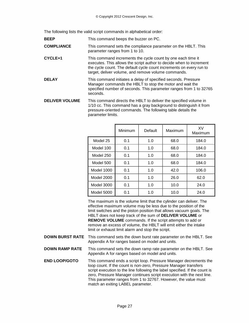
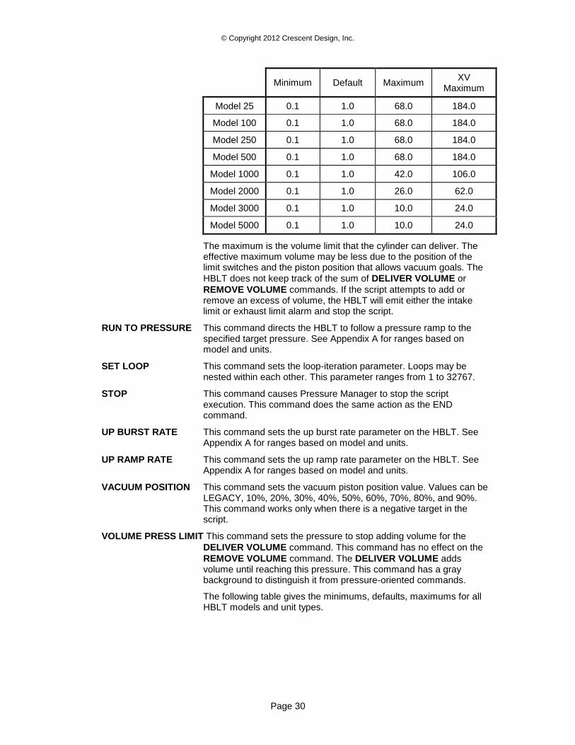
DELIVER VOLUME This command directs the HBLT to deliver the specified volume in 1/10 cc. This command has a gray background to distinguish it from pressure-oriented commands. The following table details the parameter limits.
Minimum Default Maximum XV
Maximum
Model 25 0.1 1.0 68.0 184.0
Model 100 0.1 1.0 68.0 184.0
Model 250 0.1 1.0 68.0 184.0
Model 500 0.1 1.0 68.0 184.0
Model 1000 0.1 1.0 42.0 106.0
Model 2000 0.1 1.0 26.0 62.0
Model 3000 0.1 1.0 10.0 24.0
Model 5000 0.1 1.0 10.0 24.0
The maximum is the volume limit that the cylinder can deliver. The effective maximum volume may be less due to the position of the limit switches and the piston position that allows vacuum goals. The
HBLT does not keep track of the sum of DELIVER VOLUME or
REMOVE VOLUME commands. If the script attempts to add or remove an excess of volume, the HBLT will emit either the intake limit or exhaust limit alarm and stop the script.
DOWN BURST RATE This command sets the down burst rate parameter on the HBLT. See Appendix A for ranges based on model and units.
DOWN RAMP RATE This command sets the down ramp rate parameter on the HBLT. See Appendix A for ranges based on model and units.
END LOOP/GOTO This command ends a script loop. Pressure Manager decrements the loop count. If the count is non-zero, Pressure Manager transfers script execution to the line following the label specified. If the count is zero, Pressure Manager continues script execution with the next line. This parameter ranges from 1 to 32767. However, the value must match an exiting LABEL parameter.
© Copyright 2012 Crescent Design, Inc.
Page 28
FILL CUTOFF PSI This command sets the cutoff PSI parameter on the HBLT. This parameter triggers the end of the product fill phase. This parameter ranges from 1 to 200 PSI.
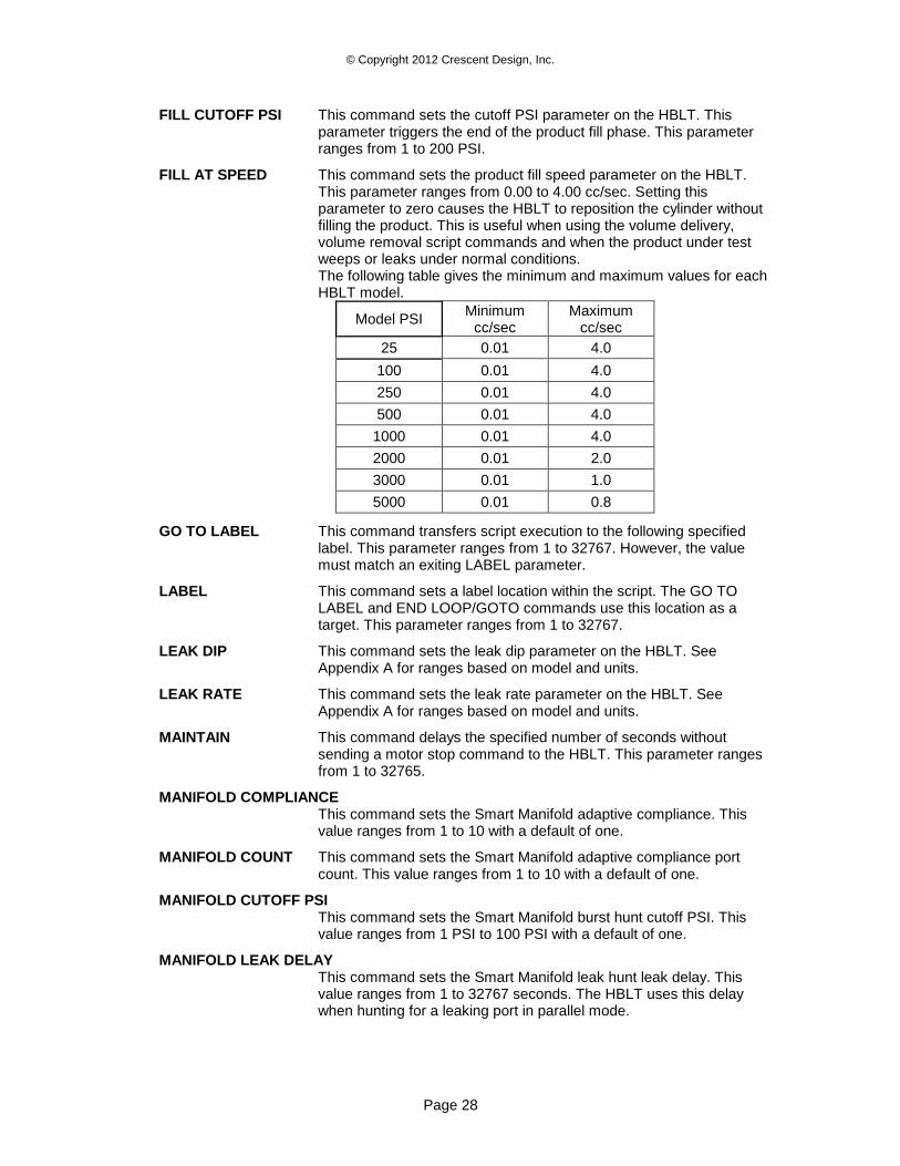
FILL AT SPEED This command sets the product fill speed parameter on the HBLT. This parameter ranges from 0.00 to 4.00 cc/sec. Setting this parameter to zero causes the HBLT to reposition the cylinder without filling the product. This is useful when using the volume delivery, volume removal script commands and when the product under test weeps or leaks under normal conditions. The following table gives the minimum and maximum values for each HBLT model.
Model PSI Minimum
cc/sec Maximum
cc/sec
25 0.01 4.0
100 0.01 4.0
250 0.01 4.0
500 0.01 4.0
1000 0.01 4.0
2000 0.01 2.0
3000 0.01 1.0
5000 0.01 0.8
GO TO LABEL This command transfers script execution to the following specified label. This parameter ranges from 1 to 32767. However, the value must match an exiting LABEL parameter.
LABEL This command sets a label location within the script. The GO TO LABEL and END LOOP/GOTO commands use this location as a target. This parameter ranges from 1 to 32767.
LEAK DIP This command sets the leak dip parameter on the HBLT. See Appendix A for ranges based on model and units.
LEAK RATE This command sets the leak rate parameter on the HBLT. See Appendix A for ranges based on model and units.
MAINTAIN This command delays the specified number of seconds without sending a motor stop command to the HBLT. This parameter ranges from 1 to 32765.
MANIFOLD COMPLIANCE This command sets the Smart Manifold adaptive compliance. This value ranges from 1 to 10 with a default of one.
MANIFOLD COUNT This command sets the Smart Manifold adaptive compliance port count. This value ranges from 1 to 10 with a default of one.
MANIFOLD CUTOFF PSI This command sets the Smart Manifold burst hunt cutoff PSI. This value ranges from 1 PSI to 100 PSI with a default of one.
MANIFOLD LEAK DELAY This command sets the Smart Manifold leak hunt leak delay. This value ranges from 1 to 32767 seconds. The HBLT uses this delay when hunting for a leaking port in parallel mode.
© Copyright 2012 Crescent Design, Inc.
Page 29
MANIFOLD LEAK MAINTAIN This command sets the Smart Manifold leak hunt maintain delay. This value ranges from 1 to 32767 seconds. The HBLT uses this delay when hunting for a leaking port in parallel mode.
MANIFOLD LEAK TARGET This command sets the Smart Manifold leak hunt target pressure. See Appendix A for ranges based on model and units.
MANIFOLD MODE This command sets the Smart Manifold testing mode. The mode can be single, sequential, or parallel.
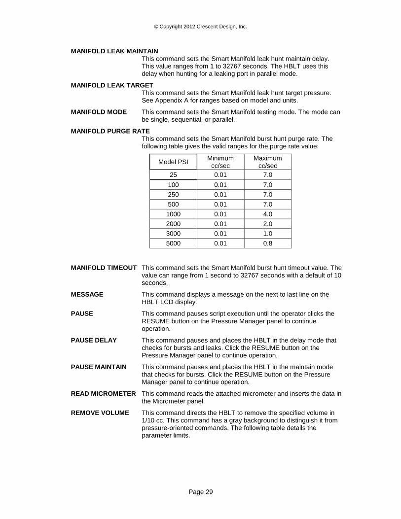
MANIFOLD PURGE RATE This command sets the Smart Manifold burst hunt purge rate. The following table gives the valid ranges for the purge rate value:
Model PSI Minimum
cc/sec Maximum
cc/sec
25 0.01 7.0
100 0.01 7.0
250 0.01 7.0
500 0.01 7.0
1000 0.01 4.0
2000 0.01 2.0
3000 0.01 1.0
5000 0.01 0.8
MANIFOLD TIMEOUT This command sets the Smart Manifold burst hunt timeout value. The value can range from 1 second to 32767 seconds with a default of 10 seconds.
MESSAGE This command displays a message on the next to last line on the HBLT LCD display.
PAUSE This command pauses script execution until the operator clicks the RESUME button on the Pressure Manager panel to continue operation.
PAUSE DELAY This command pauses and places the HBLT in the delay mode that checks for bursts and leaks. Click the RESUME button on the Pressure Manager panel to continue operation.
PAUSE MAINTAIN This command pauses and places the HBLT in the maintain mode that checks for bursts. Click the RESUME button on the Pressure Manager panel to continue operation.
READ MICROMETER This command reads the attached micrometer and inserts the data in the Micrometer panel.
REMOVE VOLUME This command directs the HBLT to remove the specified volume in 1/10 cc. This command has a gray background to distinguish it from pressure-oriented commands. The following table details the parameter limits.
© Copyright 2012 Crescent Design, Inc.
Page 30
Minimum Default Maximum XV
Maximum
Model 25 0.1 1.0 68.0 184.0
Model 100 0.1 1.0 68.0 184.0
Model 250 0.1 1.0 68.0 184.0
Model 500 0.1 1.0 68.0 184.0
Model 1000 0.1 1.0 42.0 106.0
Model 2000 0.1 1.0 26.0 62.0
Model 3000 0.1 1.0 10.0 24.0
Model 5000 0.1 1.0 10.0 24.0
The maximum is the volume limit that the cylinder can deliver. The effective maximum volume may be less due to the position of the limit switches and the piston position that allows vacuum goals. The
HBLT does not keep track of the sum of DELIVER VOLUME or
REMOVE VOLUME commands. If the script attempts to add or remove an excess of volume, the HBLT will emit either the intake limit or exhaust limit alarm and stop the script.
RUN TO PRESSURE This command directs the HBLT to follow a pressure ramp to the specified target pressure. See Appendix A for ranges based on model and units.
SET LOOP This command sets the loop-iteration parameter. Loops may be nested within each other. This parameter ranges from 1 to 32767.
STOP This command causes Pressure Manager to stop the script execution. This command does the same action as the END command.
UP BURST RATE This command sets the up burst rate parameter on the HBLT. See Appendix A for ranges based on model and units.
UP RAMP RATE This command sets the up ramp rate parameter on the HBLT. See Appendix A for ranges based on model and units.
VACUUM POSITION This command sets the vacuum piston position value. Values can be LEGACY, 10%, 20%, 30%, 40%, 50%, 60%, 70%, 80%, and 90%. This command works only when there is a negative target in the script.
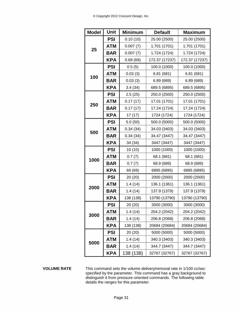
VOLUME PRESS LIMIT This command sets the pressure to stop adding volume for the
DELIVER VOLUME command. This command has no effect on the
REMOVE VOLUME command. The DELIVER VOLUME adds volume until reaching this pressure. This command has a gray background to distinguish it from pressure-oriented commands.
The following table gives the minimums, defaults, maximums for all HBLT models and unit types.
© Copyright 2012 Crescent Design, Inc.
Page 31
Model Unit
s Minimum Default Maximum
25
PSI 0.10 (10) 25.00 (2500) 25.00 (2500)
ATM 0.007 (7) 1.701 (1701) 1.701 (1701)
BAR 0.007 (7) 1.724 (1724) 1.724 (1724)
KPA 0.69 (69) 172.37 (17237) 172.37 (17237)
100
PSI 0.5 (5) 100.0 (1000) 100.0 (1000)
ATM 0.03 (3) 6.81 (681) 6.81 (681)
BAR 0.03 (3) 6.89 (689) 6.89 (689)
KPA 3.4 (34) 689.5 (6895) 689.5 (6895)
250
PSI 2.5 (25) 250.0 (2500) 250.0 (2500)
ATM 0.17 (17) 17.01 (1701) 17.01 (1701)
BAR 0.17 (17) 17.24 (1724) 17.24 (1724)
KPA 17 (17) 1724 (1724) 1724 (1724)
500
PSI 5.0 (50) 500.0 (5000) 500.0 (5000)
ATM 0.34 (34) 34.03 (3403) 34.03 (3403)
BAR 0.34 (34) 34.47 (3447) 34.47 (3447)
KPA 34 (34) 3447 (3447) 3447 (3447)
1000
PSI 10 (10) 1000 (1000) 1000 (1000)
ATM 0.7 (7) 68.1 (681) 68.1 (681)
BAR 0.7 (7) 68.9 (689) 68.9 (689)
KPA 69 (69) 6895 (6895) 6895 (6895)
2000
PSI 20 (20) 2000 (2000) 2000 (2000)
ATM 1.4 (14) 136.1 (1361) 136.1 (1361)
BAR 1.4 (14) 137.9 (1379) 137.9 (1379)
KPA 138 (138) 13790 (13790) 13790 (13790)
3000
PSI 20 (20) 3000 (3000) 3000 (3000)
ATM 1.4 (14) 204.2 (2042) 204.2 (2042)
BAR 1.4 (14) 206.8 (2068) 206.8 (2068)
KPA 138 (138) 20684 (20684) 20684 (20684)
5000
PSI 20 (20) 5000 (5000) 5000 (5000)
ATM 1.4 (14) 340.3 (3403) 340.3 (3403)
BAR 1.4 (14) 344.7 (3447) 344.7 (3447)
KPA 138 (138) 32767 (32767) 32767 (32767)
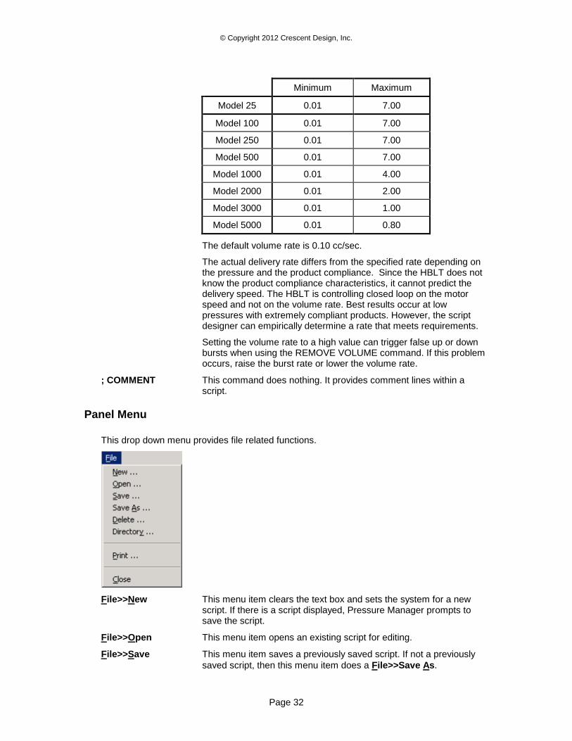
VOLUME RATE This command sets the volume delivery/removal rate in 1/100 cc/sec specified by the parameter. This command has a gray background to distinguish it from pressure-oriented commands. The following table details the ranges for this parameter.
© Copyright 2012 Crescent Design, Inc.
Page 32
Minimum Maximum
Model 25 0.01 7.00
Model 100 0.01 7.00
Model 250 0.01 7.00
Model 500 0.01 7.00
Model 1000 0.01 4.00
Model 2000 0.01 2.00
Model 3000 0.01 1.00
Model 5000 0.01 0.80
The default volume rate is 0.10 cc/sec.
The actual delivery rate differs from the specified rate depending on the pressure and the product compliance. Since the HBLT does not know the product compliance characteristics, it cannot predict the delivery speed. The HBLT is controlling closed loop on the motor speed and not on the volume rate. Best results occur at low pressures with extremely compliant products. However, the script designer can empirically determine a rate that meets requirements.
Setting the volume rate to a high value can trigger false up or down bursts when using the REMOVE VOLUME command. If this problem occurs, raise the burst rate or lower the volume rate.
; COMMENT This command does nothing. It provides comment lines within a script.
Panel Menu
This drop down menu provides file related functions.
File>>New This menu item clears the text box and sets the system for a new script. If there is a script displayed, Pressure Manager prompts to save the script.
File>>Open This menu item opens an existing script for editing.
File>>Save This menu item saves a previously saved script. If not a previously
saved script, then this menu item does a File>>Save As.
© Copyright 2012 Crescent Design, Inc.
Page 33
File>>Save As This menu item saves a script with a new name.
File>>Delete This menu item deletes the currently open script.
File>>Directory This menu item sets the default directory for opening and saving scripts.
File>>Print This menu item prints the currently open script on the default system printer with a header and line numbers.
File>>Close This menu item closes the panel. If a script is open, Pressure Manager prompts for a save.
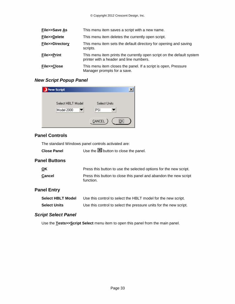
New Script Popup Panel
Panel Controls
The standard Windows panel controls activated are:
Close Panel Use the button to close the panel.
Panel Buttons
OK Press this button to use the selected options for the new script.
Cancel Press this button to close this panel and abandon the new script function.
Panel Entry
Select HBLT Model Use this control to select the HBLT model for the new script.
Select Units Use this control to select the pressure units for the new script.
Script Select Panel
Use the Tests>>Script Select menu item to open this panel from the main panel.
© Copyright 2012 Crescent Design, Inc.
Page 34
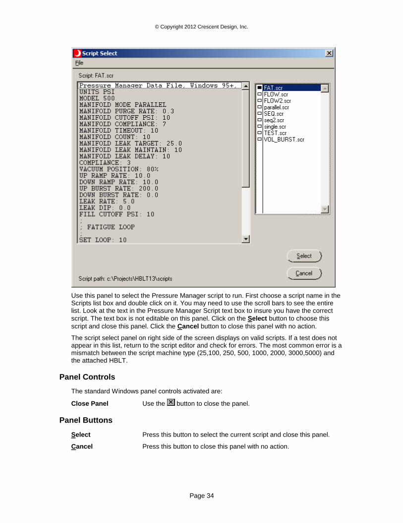
Use this panel to select the Pressure Manager script to run. First choose a script name in the Scripts list box and double click on it. You may need to use the scroll bars to see the entire list. Look at the text in the Pressure Manager Script text box to insure you have the correct
script. The text box is not editable on this panel. Click on the Select button to choose this
script and close this panel. Click the Cancel button to close this panel with no action.
The script select panel on right side of the screen displays on valid scripts. If a test does not appear in this list, return to the script editor and check for errors. The most common error is a mismatch between the script machine type (25,100, 250, 500, 1000, 2000, 3000,5000) and the attached HBLT.
Panel Controls
The standard Windows panel controls activated are:
Close Panel Use the button to close the panel.
Panel Buttons
Select Press this button to select the current script and close this panel.
Cancel Press this button to close this panel with no action.
© Copyright 2012 Crescent Design, Inc.
Page 35
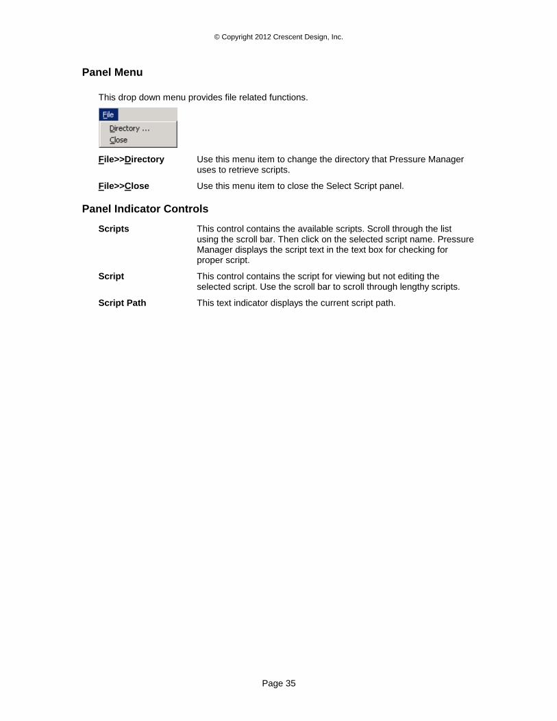
Panel Menu
This drop down menu provides file related functions.
File>>Directory Use this menu item to change the directory that Pressure Manager uses to retrieve scripts.
File>>Close Use this menu item to close the Select Script panel.
Panel Indicator Controls
Scripts This control contains the available scripts. Scroll through the list using the scroll bar. Then click on the selected script name. Pressure Manager displays the script text in the text box for checking for proper script.
Script This control contains the script for viewing but not editing the selected script. Use the scroll bar to scroll through lengthy scripts.
Script Path This text indicator displays the current script path.
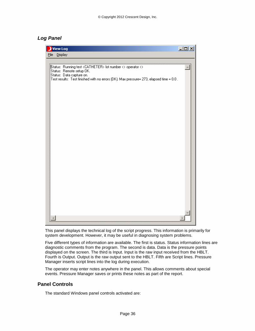
© Copyright 2012 Crescent Design, Inc.
Page 36
Log Panel
This panel displays the technical log of the script progress. This information is primarily for system development. However, it may be useful in diagnosing system problems.
Five different types of information are available. The first is status. Status information lines are diagnostic comments from the program. The second is data. Data is the pressure points displayed on the screen. The third is Input. Input is the raw input received from the HBLT. Fourth is Output. Output is the raw output sent to the HBLT. Fifth are Script lines. Pressure Manager inserts script lines into the log during execution.
The operator may enter notes anywhere in the panel. This allows comments about special events. Pressure Manager saves or prints these notes as part of the report.
Panel Controls
The standard Windows panel controls activated are:
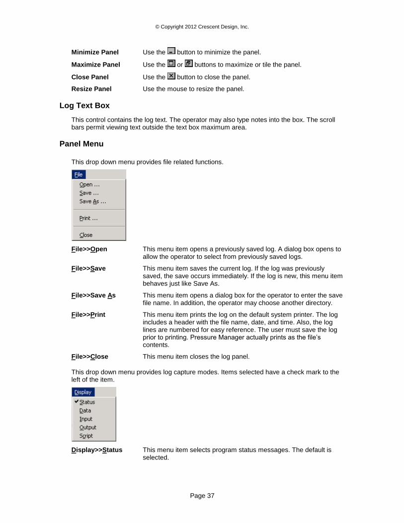
© Copyright 2012 Crescent Design, Inc.
Page 37
Minimize Panel Use the button to minimize the panel.
Maximize Panel Use the or buttons to maximize or tile the panel.
Close Panel Use the button to close the panel.
Resize Panel Use the mouse to resize the panel.
Log Text Box
This control contains the log text. The operator may also type notes into the box. The scroll bars permit viewing text outside the text box maximum area.
Panel Menu
This drop down menu provides file related functions.
File>>Open This menu item opens a previously saved log. A dialog box opens to allow the operator to select from previously saved logs.
File>>Save This menu item saves the current log. If the log was previously saved, the save occurs immediately. If the log is new, this menu item behaves just like Save As.
File>>Save As This menu item opens a dialog box for the operator to enter the save file name. In addition, the operator may choose another directory.
File>>Print This menu item prints the log on the default system printer. The log includes a header with the file name, date, and time. Also, the log lines are numbered for easy reference. The user must save the log prior to printing. Pressure Manager actually prints as the file’s contents.
File>>Close This menu item closes the log panel.
This drop down menu provides log capture modes. Items selected have a check mark to the left of the item.
Display>>Status This menu item selects program status messages. The default is selected.
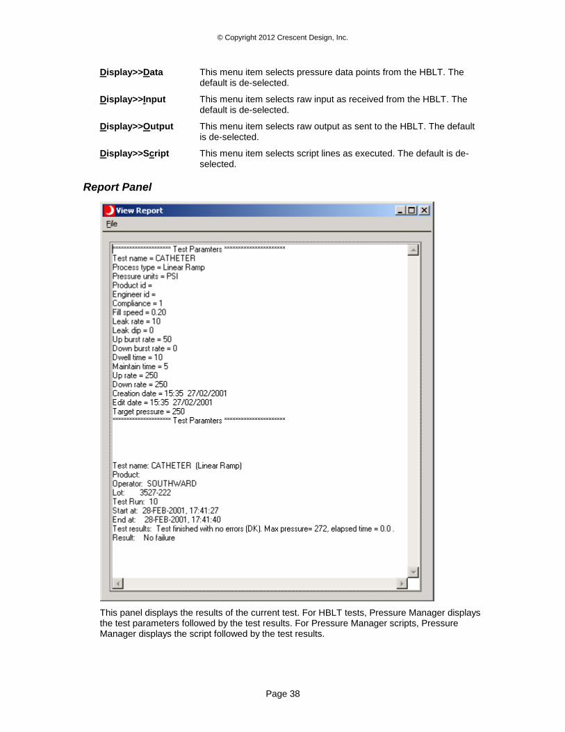
© Copyright 2012 Crescent Design, Inc.
Page 38
Display>>Data This menu item selects pressure data points from the HBLT. The default is de-selected.
Display>>Input This menu item selects raw input as received from the HBLT. The default is de-selected.
Display>>Output This menu item selects raw output as sent to the HBLT. The default is de-selected.
Display>>Script This menu item selects script lines as executed. The default is de-selected.
Report Panel
This panel displays the results of the current test. For HBLT tests, Pressure Manager displays the test parameters followed by the test results. For Pressure Manager scripts, Pressure Manager displays the script followed by the test results.
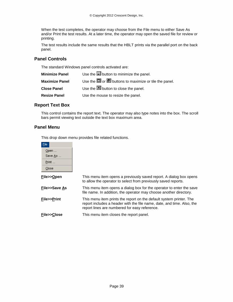
© Copyright 2012 Crescent Design, Inc.
Page 39
When the test completes, the operator may choose from the File menu to either Save As and/or Print the test results. At a later time, the operator may open the saved file for review or printing.
The test results include the same results that the HBLT prints via the parallel port on the back panel.
Panel Controls
The standard Windows panel controls activated are:
Minimize Panel Use the button to minimize the panel.
Maximize Panel Use the or buttons to maximize or tile the panel.
Close Panel Use the button to close the panel.
Resize Panel Use the mouse to resize the panel.
Report Text Box
This control contains the report text. The operator may also type notes into the box. The scroll bars permit viewing text outside the text box maximum area.
Panel Menu
This drop down menu provides file related functions.
File>>Open This menu item opens a previously saved report. A dialog box opens to allow the operator to select from previously saved reports.
File>>Save As This menu item opens a dialog box for the operator to enter the save file name. In addition, the operator may choose another directory.
File>>Print This menu item prints the report on the default system printer. The report includes a header with the file name, date, and time. Also, the report lines are numbered for easy reference.
File>>Close This menu item closes the report panel.
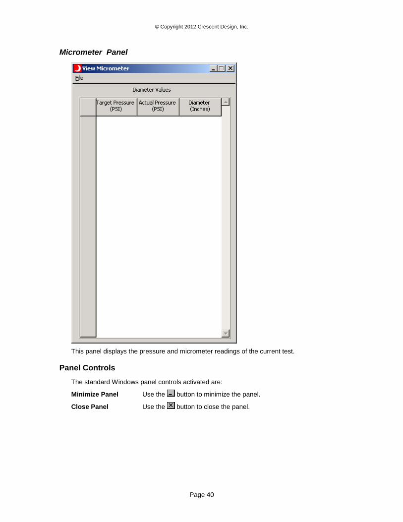
© Copyright 2012 Crescent Design, Inc.
Page 40
Micrometer Panel
This panel displays the pressure and micrometer readings of the current test.
Panel Controls
The standard Windows panel controls activated are:
Minimize Panel Use the button to minimize the panel.
Close Panel Use the button to close the panel.
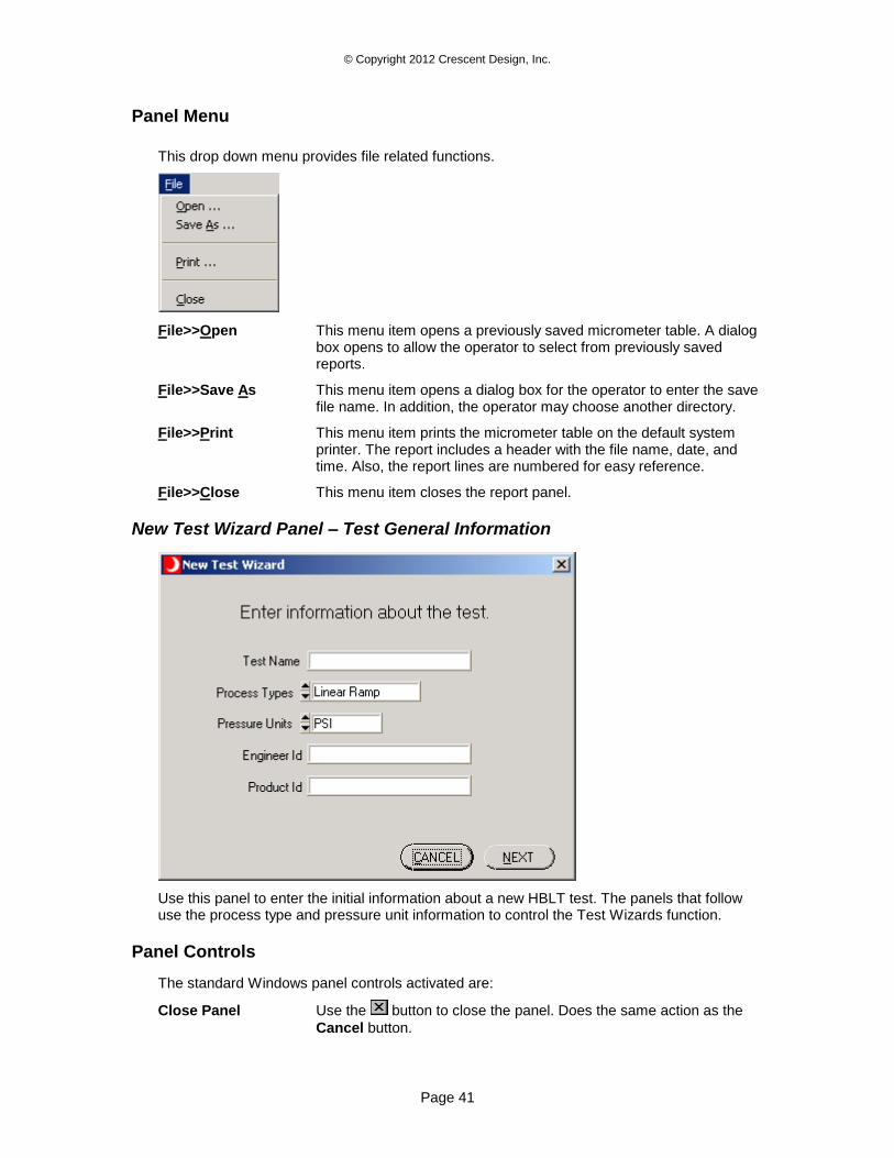
© Copyright 2012 Crescent Design, Inc.
Page 41
Panel Menu
This drop down menu provides file related functions.
File>>Open This menu item opens a previously saved micrometer table. A dialog box opens to allow the operator to select from previously saved reports.
File>>Save As This menu item opens a dialog box for the operator to enter the save file name. In addition, the operator may choose another directory.
File>>Print This menu item prints the micrometer table on the default system printer. The report includes a header with the file name, date, and time. Also, the report lines are numbered for easy reference.
File>>Close This menu item closes the report panel.
New Test Wizard Panel – Test General Information
Use this panel to enter the initial information about a new HBLT test. The panels that follow use the process type and pressure unit information to control the Test Wizards function.
Panel Controls
The standard Windows panel controls activated are:
Close Panel Use the button to close the panel. Does the same action as the
Cancel button.
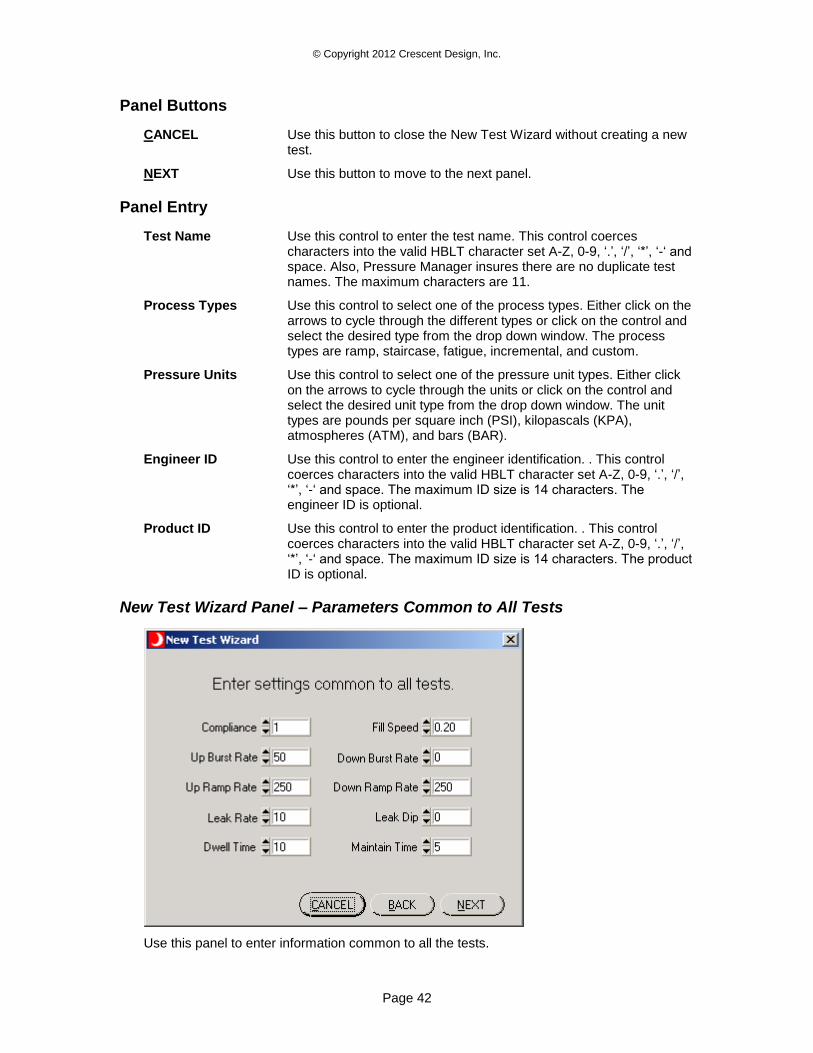
© Copyright 2012 Crescent Design, Inc.
Page 42
Panel Buttons
CANCEL Use this button to close the New Test Wizard without creating a new test.
NEXT Use this button to move to the next panel.
Panel Entry
Test Name Use this control to enter the test name. This control coerces characters into the valid HBLT character set A-Z, 0-9, ‘.’, ‘/’, ‘*’, ‘-‘ and space. Also, Pressure Manager insures there are no duplicate test names. The maximum characters are 11.
Process Types Use this control to select one of the process types. Either click on the arrows to cycle through the different types or click on the control and select the desired type from the drop down window. The process types are ramp, staircase, fatigue, incremental, and custom.
Pressure Units Use this control to select one of the pressure unit types. Either click on the arrows to cycle through the units or click on the control and select the desired unit type from the drop down window. The unit types are pounds per square inch (PSI), kilopascals (KPA), atmospheres (ATM), and bars (BAR).
Engineer ID Use this control to enter the engineer identification. . This control coerces characters into the valid HBLT character set A-Z, 0-9, ‘.’, ‘/’, ‘*’, ‘-‘ and space. The maximum ID size is 14 characters. The engineer ID is optional.
Product ID Use this control to enter the product identification. . This control coerces characters into the valid HBLT character set A-Z, 0-9, ‘.’, ‘/’, ‘*’, ‘-‘ and space. The maximum ID size is 14 characters. The product ID is optional.
New Test Wizard Panel – Parameters Common to All Tests
Use this panel to enter information common to all the tests.
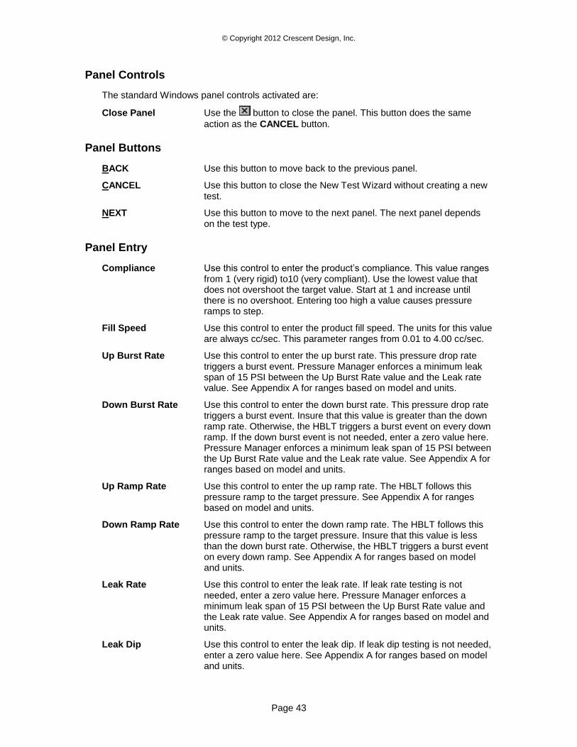
© Copyright 2012 Crescent Design, Inc.
Page 43
Panel Controls
The standard Windows panel controls activated are:
Close Panel Use the button to close the panel. This button does the same
action as the CANCEL button.
Panel Buttons
BACK Use this button to move back to the previous panel.
CANCEL Use this button to close the New Test Wizard without creating a new test.
NEXT Use this button to move to the next panel. The next panel depends on the test type.
Panel Entry
Compliance Use this control to enter the product’s compliance. This value ranges from 1 (very rigid) to10 (very compliant). Use the lowest value that does not overshoot the target value. Start at 1 and increase until there is no overshoot. Entering too high a value causes pressure ramps to step.
Fill Speed Use this control to enter the product fill speed. The units for this value are always cc/sec. This parameter ranges from 0.01 to 4.00 cc/sec.
Up Burst Rate Use this control to enter the up burst rate. This pressure drop rate triggers a burst event. Pressure Manager enforces a minimum leak span of 15 PSI between the Up Burst Rate value and the Leak rate value. See Appendix A for ranges based on model and units.
Down Burst Rate Use this control to enter the down burst rate. This pressure drop rate triggers a burst event. Insure that this value is greater than the down ramp rate. Otherwise, the HBLT triggers a burst event on every down ramp. If the down burst event is not needed, enter a zero value here. Pressure Manager enforces a minimum leak span of 15 PSI between the Up Burst Rate value and the Leak rate value. See Appendix A for ranges based on model and units.
Up Ramp Rate Use this control to enter the up ramp rate. The HBLT follows this pressure ramp to the target pressure. See Appendix A for ranges based on model and units.
Down Ramp Rate Use this control to enter the down ramp rate. The HBLT follows this pressure ramp to the target pressure. Insure that this value is less than the down burst rate. Otherwise, the HBLT triggers a burst event on every down ramp. See Appendix A for ranges based on model and units.
Leak Rate Use this control to enter the leak rate. If leak rate testing is not needed, enter a zero value here. Pressure Manager enforces a minimum leak span of 15 PSI between the Up Burst Rate value and the Leak rate value. See Appendix A for ranges based on model and units.
Leak Dip Use this control to enter the leak dip. If leak dip testing is not needed, enter a zero value here. See Appendix A for ranges based on model and units.
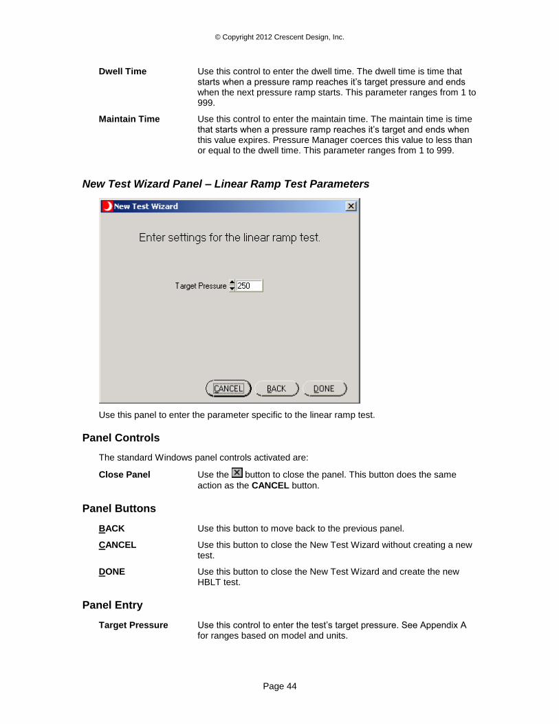
© Copyright 2012 Crescent Design, Inc.
Page 44
Dwell Time Use this control to enter the dwell time. The dwell time is time that starts when a pressure ramp reaches it’s target pressure and ends when the next pressure ramp starts. This parameter ranges from 1 to 999.
Maintain Time Use this control to enter the maintain time. The maintain time is time that starts when a pressure ramp reaches it’s target and ends when this value expires. Pressure Manager coerces this value to less than or equal to the dwell time. This parameter ranges from 1 to 999.
New Test Wizard Panel – Linear Ramp Test Parameters
Use this panel to enter the parameter specific to the linear ramp test.
Panel Controls
The standard Windows panel controls activated are:
Close Panel Use the button to close the panel. This button does the same
action as the CANCEL button.
Panel Buttons
BACK Use this button to move back to the previous panel.
CANCEL Use this button to close the New Test Wizard without creating a new test.
DONE Use this button to close the New Test Wizard and create the new HBLT test.
Panel Entry
Target Pressure Use this control to enter the test’s target pressure. See Appendix A for ranges based on model and units.
© Copyright 2012 Crescent Design, Inc.
Page 45
New Test Wizard Panel – Staircase Test Parameters
Use this panel to enter the parameters specific to the staircase test.
Panel Controls
The standard Windows panel controls activated are:
Close Panel Use the button to close the panel. This button does the same
action as the CANCEL button.
Panel Buttons
BACK Use this button to move back to the previous panel.
CANCEL Use this button to close the New Test Wizard without creating a new test.
DONE Use this button to close the New Test Wizard and create the new HBLT test.
Panel Entry
Max Pressure Use this control to enter the maximum pressure for the staircase test. Max Pressure caps the Initial Pressure. Changing the Max Pressure below the Initial Pressure coerces the Initial Pressure below the Max Pressure. See Appendix A for ranges based on model and units.
Incremental Pressure Use this control to enter the incremental pressure for the staircase test. See Appendix A for ranges based on model and units.
Initial Pressure Use this control to enter the initial pressure for the staircase test. Max Pressure caps the Initial Pressure. See Appendix A for ranges based on model and units.
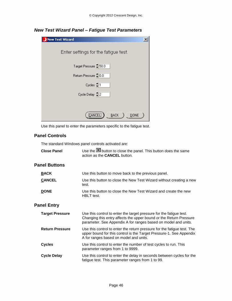
© Copyright 2012 Crescent Design, Inc.
Page 46
New Test Wizard Panel – Fatigue Test Parameters
Use this panel to enter the parameters specific to the fatigue test.
Panel Controls
The standard Windows panel controls activated are:
Close Panel Use the button to close the panel. This button does the same
action as the CANCEL button.
Panel Buttons
BACK Use this button to move back to the previous panel.
CANCEL Use this button to close the New Test Wizard without creating a new test.
DONE Use this button to close the New Test Wizard and create the new HBLT test.
Panel Entry
Target Pressure Use this control to enter the target pressure for the fatigue test. Changing this entry affects the upper bound or the Return Pressure parameter. See Appendix A for ranges based on model and units.
Return Pressure Use this control to enter the return pressure for the fatigue test. The upper bound for this control is the Target Pressure-1. See Appendix A for ranges based on model and units.
Cycles Use this control to enter the number of test cycles to run. This parameter ranges from 1 to 9999.
Cycle Delay Use this control to enter the delay in seconds between cycles for the fatigue test. This parameter ranges from 1 to 99.
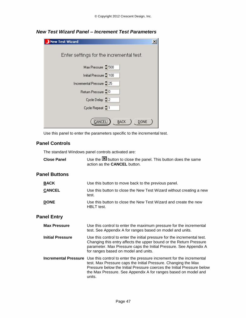
© Copyright 2012 Crescent Design, Inc.
Page 47
New Test Wizard Panel – Increment Test Parameters
Use this panel to enter the parameters specific to the incremental test.
Panel Controls
The standard Windows panel controls activated are:
Close Panel Use the button to close the panel. This button does the same
action as the CANCEL button.
Panel Buttons
BACK Use this button to move back to the previous panel.
CANCEL Use this button to close the New Test Wizard without creating a new test.
DONE Use this button to close the New Test Wizard and create the new HBLT test.
Panel Entry
Max Pressure Use this control to enter the maximum pressure for the incremental test. See Appendix A for ranges based on model and units.
Initial Pressure Use this control to enter the initial pressure for the incremental test. Changing this entry affects the upper bound or the Return Pressure parameter. Max Pressure caps the Initial Pressure. See Appendix A for ranges based on model and units.
Incremental Pressure Use this control to enter the pressure increment for the incremental test. Max Pressure caps the Initial Pressure. Changing the Max Pressure below the Initial Pressure coerces the Initial Pressure below the Max Pressure. See Appendix A for ranges based on model and units.
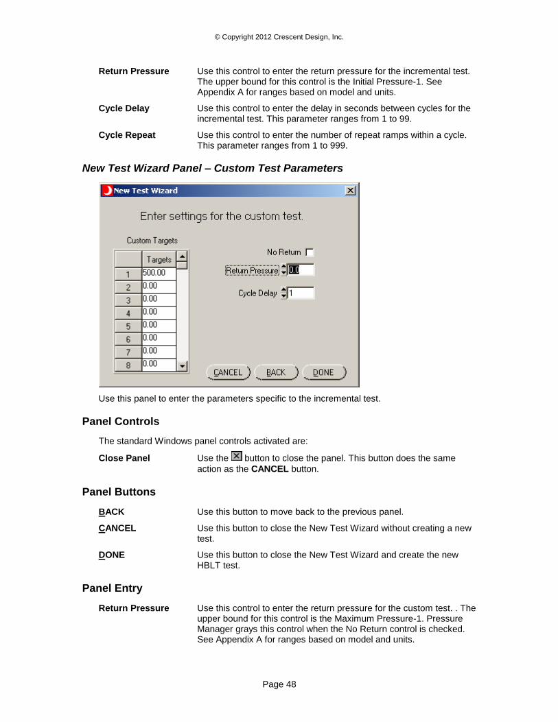
© Copyright 2012 Crescent Design, Inc.
Page 48
Return Pressure Use this control to enter the return pressure for the incremental test. The upper bound for this control is the Initial Pressure-1. See Appendix A for ranges based on model and units.
Cycle Delay Use this control to enter the delay in seconds between cycles for the incremental test. This parameter ranges from 1 to 99.
Cycle Repeat Use this control to enter the number of repeat ramps within a cycle. This parameter ranges from 1 to 999.
New Test Wizard Panel – Custom Test Parameters
Use this panel to enter the parameters specific to the incremental test.
Panel Controls
The standard Windows panel controls activated are:
Close Panel Use the button to close the panel. This button does the same
action as the CANCEL button.
Panel Buttons
BACK Use this button to move back to the previous panel.
CANCEL Use this button to close the New Test Wizard without creating a new test.
DONE Use this button to close the New Test Wizard and create the new HBLT test.
Panel Entry
Return Pressure Use this control to enter the return pressure for the custom test. . The upper bound for this control is the Maximum Pressure-1. Pressure Manager grays this control when the No Return control is checked. See Appendix A for ranges based on model and units.
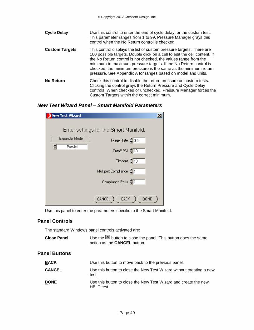
© Copyright 2012 Crescent Design, Inc.
Page 49
Cycle Delay Use this control to enter the end of cycle delay for the custom test. This parameter ranges from 1 to 99. Pressure Manager grays this control when the No Return control is checked.
Custom Targets This control displays the list of custom pressure targets. There are 100 possible targets. Double click on a cell to edit the cell content. If the No Return control is not checked, the values range from the minimum to maximum pressure targets. If the No Return control is checked, the minimum pressure is the same as the minimum return pressure. See Appendix A for ranges based on model and units.
No Return Check this control to disable the return pressure on custom tests. Clicking the control grays the Return Pressure and Cycle Delay controls. When checked or unchecked, Pressure Manager forces the Custom Targets within the correct minimum.
New Test Wizard Panel – Smart Manifold Parameters
Use this panel to enter the parameters specific to the Smart Manifold.
Panel Controls
The standard Windows panel controls activated are:
Close Panel Use the button to close the panel. This button does the same
action as the CANCEL button.
Panel Buttons
BACK Use this button to move back to the previous panel.
CANCEL Use this button to close the New Test Wizard without creating a new test.
DONE Use this button to close the New Test Wizard and create the new HBLT test.
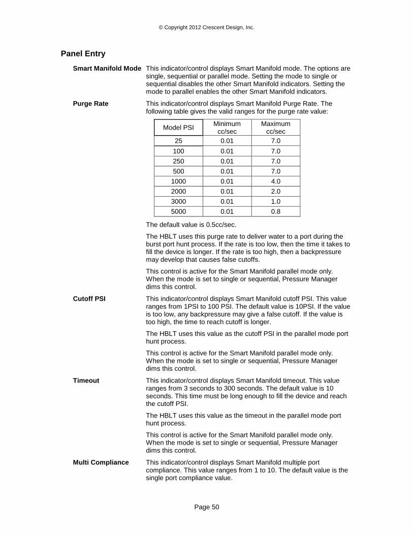
© Copyright 2012 Crescent Design, Inc.
Page 50
Panel Entry
Smart Manifold Mode This indicator/control displays Smart Manifold mode. The options are single, sequential or parallel mode. Setting the mode to single or sequential disables the other Smart Manifold indicators. Setting the mode to parallel enables the other Smart Manifold indicators.
Purge Rate This indicator/control displays Smart Manifold Purge Rate. The following table gives the valid ranges for the purge rate value:
Model PSI Minimum
cc/sec Maximum
cc/sec
25 0.01 7.0
100 0.01 7.0
250 0.01 7.0
500 0.01 7.0
1000 0.01 4.0
2000 0.01 2.0
3000 0.01 1.0
5000 0.01 0.8
The default value is 0.5cc/sec.
The HBLT uses this purge rate to deliver water to a port during the burst port hunt process. If the rate is too low, then the time it takes to fill the device is longer. If the rate is too high, then a backpressure may develop that causes false cutoffs.
This control is active for the Smart Manifold parallel mode only. When the mode is set to single or sequential, Pressure Manager dims this control.
Cutoff PSI This indicator/control displays Smart Manifold cutoff PSI. This value ranges from 1PSI to 100 PSI. The default value is 10PSI. If the value is too low, any backpressure may give a false cutoff. If the value is too high, the time to reach cutoff is longer.
The HBLT uses this value as the cutoff PSI in the parallel mode port hunt process.
This control is active for the Smart Manifold parallel mode only. When the mode is set to single or sequential, Pressure Manager dims this control.
Timeout This indicator/control displays Smart Manifold timeout. This value ranges from 3 seconds to 300 seconds. The default value is 10 seconds. This time must be long enough to fill the device and reach the cutoff PSI.
The HBLT uses this value as the timeout in the parallel mode port hunt process.
This control is active for the Smart Manifold parallel mode only. When the mode is set to single or sequential, Pressure Manager dims this control.
Multi Compliance This indicator/control displays Smart Manifold multiple port compliance. This value ranges from 1 to 10. The default value is the single port compliance value.
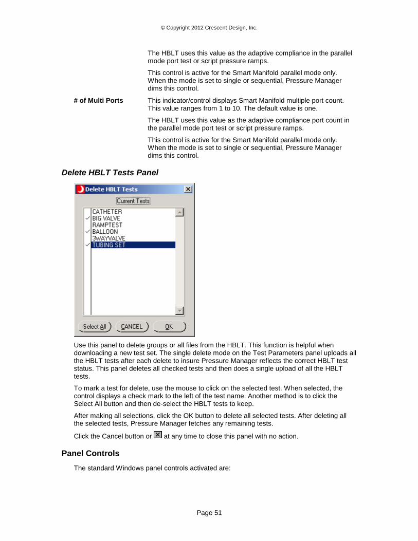
© Copyright 2012 Crescent Design, Inc.
Page 51
The HBLT uses this value as the adaptive compliance in the parallel mode port test or script pressure ramps.
This control is active for the Smart Manifold parallel mode only. When the mode is set to single or sequential, Pressure Manager dims this control.
# of Multi Ports This indicator/control displays Smart Manifold multiple port count. This value ranges from 1 to 10. The default value is one.
The HBLT uses this value as the adaptive compliance port count in the parallel mode port test or script pressure ramps.
This control is active for the Smart Manifold parallel mode only. When the mode is set to single or sequential, Pressure Manager dims this control.
Delete HBLT Tests Panel
Use this panel to delete groups or all files from the HBLT. This function is helpful when downloading a new test set. The single delete mode on the Test Parameters panel uploads all the HBLT tests after each delete to insure Pressure Manager reflects the correct HBLT test status. This panel deletes all checked tests and then does a single upload of all the HBLT tests.
To mark a test for delete, use the mouse to click on the selected test. When selected, the control displays a check mark to the left of the test name. Another method is to click the Select All button and then de-select the HBLT tests to keep.
After making all selections, click the OK button to delete all selected tests. After deleting all the selected tests, Pressure Manager fetches any remaining tests.
Click the Cancel button or at any time to close this panel with no action.
Panel Controls
The standard Windows panel controls activated are:
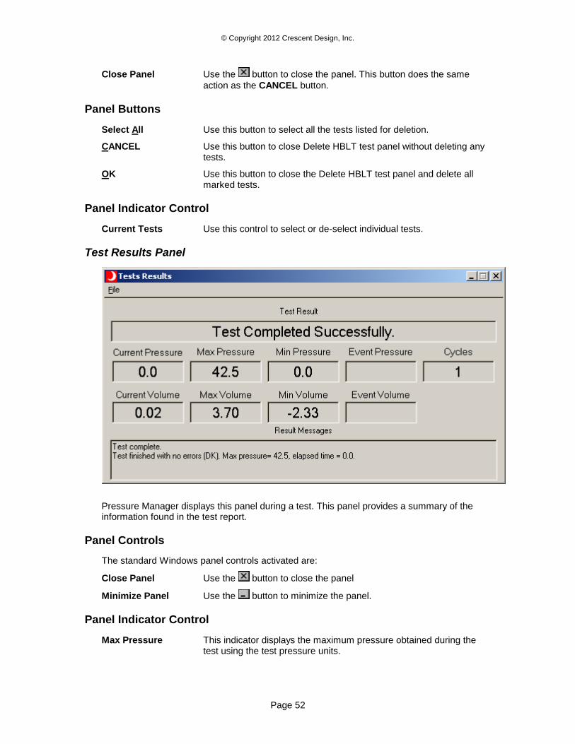
© Copyright 2012 Crescent Design, Inc.
Page 52
Close Panel Use the button to close the panel. This button does the same
action as the CANCEL button.
Panel Buttons
Select All Use this button to select all the tests listed for deletion.
CANCEL Use this button to close Delete HBLT test panel without deleting any tests.
OK Use this button to close the Delete HBLT test panel and delete all marked tests.
Panel Indicator Control
Current Tests Use this control to select or de-select individual tests.
Test Results Panel
Pressure Manager displays this panel during a test. This panel provides a summary of the information found in the test report.
Panel Controls
The standard Windows panel controls activated are:
Close Panel Use the button to close the panel
Minimize Panel Use the button to minimize the panel.
Panel Indicator Control
Max Pressure This indicator displays the maximum pressure obtained during the test using the test pressure units.
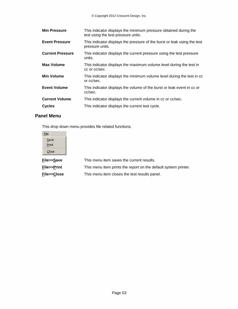
© Copyright 2012 Crescent Design, Inc.
Page 53
Min Pressure This indicator displays the minimum pressure obtained during the test using the test pressure units.
Event Pressure This indicator displays the pressure of the burst or leak using the test pressure units.
Current Pressure This indicator displays the current pressure using the test pressure units.
Max Volume This indicator displays the maximum volume level during the test in cc or cc/sec.
Min Volume This indicator displays the minimum volume level during the test in cc or cc/sec.
Event Volume This indicator displays the volume of the burst or leak event in cc or cc/sec.
Current Volume This indicator displays the current volume in cc or cc/sec.
Cycles This indicator displays the current test cycle.
Panel Menu
This drop down menu provides file related functions.
File>>Save This menu item saves the current results.
File>>Print This menu item prints the report on the default system printer.
File>>Close This menu item closes the test results panel.
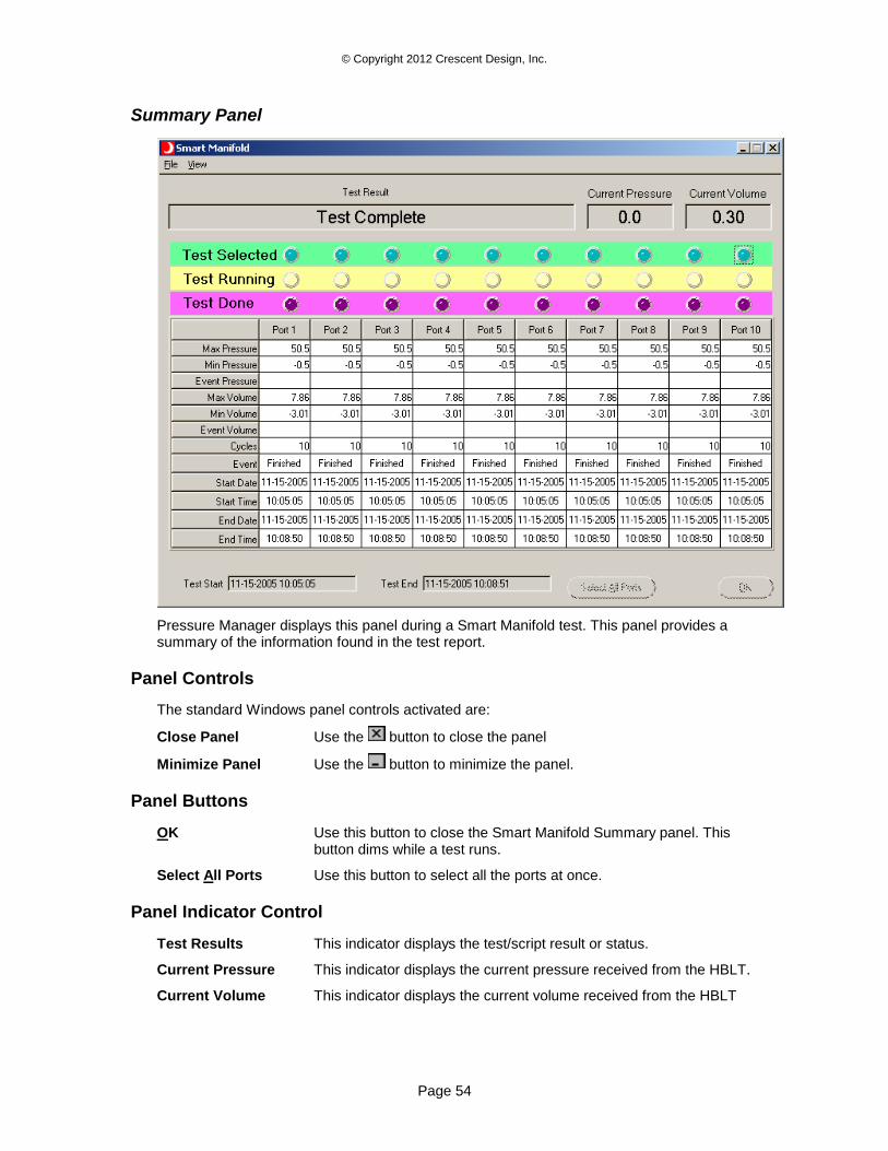
© Copyright 2012 Crescent Design, Inc.
Page 54
Summary Panel
Pressure Manager displays this panel during a Smart Manifold test. This panel provides a summary of the information found in the test report.
Panel Controls
The standard Windows panel controls activated are:
Close Panel Use the button to close the panel
Minimize Panel Use the button to minimize the panel.
Panel Buttons
OK Use this button to close the Smart Manifold Summary panel. This button dims while a test runs.
Select All Ports Use this button to select all the ports at once.
Panel Indicator Control
Test Results This indicator displays the test/script result or status.
Current Pressure This indicator displays the current pressure received from the HBLT.
Current Volume This indicator displays the current volume received from the HBLT

© Copyright 2012 Crescent Design, Inc.
Page 55
Test Selected These indicators display the selected status of each port. Click these controls to toggle on/off the corresponding port on the Smart Manifold.
Test Running These Indicators display the current run status of each Smart Manifold port. When the LED is on, the port is under test. When the LED flashes, the Smart Manifold is doing a hunt test on that port only.
Test Done These indicator display the final port status. When the LED is on, the test completed successfully for that port. When the LED flashes, the test completed with a burst or leak event.
Max Pressure This indicator displays the maximum pressure obtained during the test using the test pressure units for each port.
Min Pressure This indicator displays the minimum pressure obtained during the test using the test pressure units for each port.
Event Pressure This indicator displays the pressure of the burst or leak using the test pressure units for each port.
Max Volume This indicator displays the maximum volume level during the test in cc or cc/sec for each port.
Min Volume This indicator displays the minimum volume level during the test in cc or cc/sec for each port.
Event Volume This indicator displays the volume of the burst or leak event in cc or cc/sec for each port.
Cycles This indicator displays the current test cycle for each port.
Event This indicator displays the test end event for each port.
Start Date This indicator displays the starting date for each port.
Start Time This indicator displays the starting time for each port.
End Date This indicator displays the ending date for each port.
End Time This indicator displays the ending time for each port.
Test Start This indicator displays the starting date and time for the entire test.
Test End This indicator displays the ending date and time for the entire test.
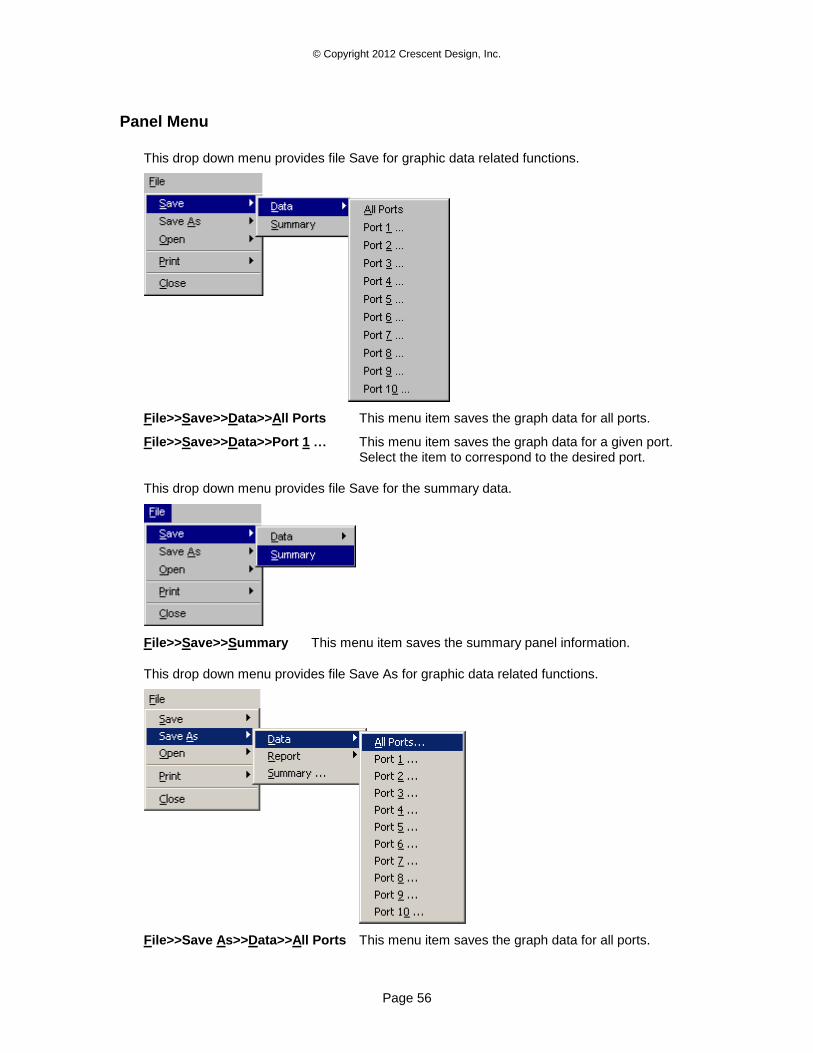
© Copyright 2012 Crescent Design, Inc.
Page 56
Panel Menu
This drop down menu provides file Save for graphic data related functions.
File>>Save>>Data>>All Ports This menu item saves the graph data for all ports.
File>>Save>>Data>>Port 1 … This menu item saves the graph data for a given port. Select the item to correspond to the desired port.
This drop down menu provides file Save for the summary data.
File>>Save>>Summary This menu item saves the summary panel information.
This drop down menu provides file Save As for graphic data related functions.
File>>Save As>>Data>>All Ports This menu item saves the graph data for all ports.
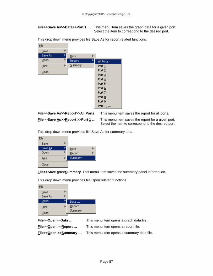
© Copyright 2012 Crescent Design, Inc.
Page 57
File>>Save As>>Data>>Port 1 … This menu item saves the graph data for a given port. Select the item to correspond to the desired port.
This drop down menu provides file Save As for report related functions.
File>>Save As>>Report>>All Ports This menu item saves the report for all ports.
File>>Save As>>Report >>Port 1 … This menu item saves the report for a given port. Select the item to correspond to the desired port.
This drop down menu provides file Save As for summary data.
File>>Save As>>Summary This menu item saves the summary panel information.
This drop down menu provides file Open related functions.
File>>Open>>Data … This menu item opens a graph data file.
File>>Open >>Report … This menu item opens a report file.
File>>Open >>Summary … This menu item opens a summary data file.
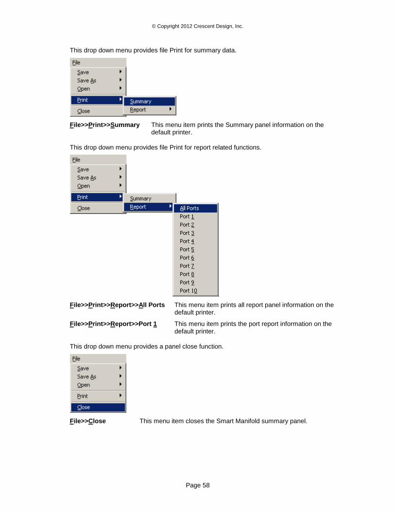
© Copyright 2012 Crescent Design, Inc.
Page 58
This drop down menu provides file Print for summary data.
File>>Print>>Summary This menu item prints the Summary panel information on the default printer.
This drop down menu provides file Print for report related functions.
File>>Print>>Report>>All Ports This menu item prints all report panel information on the default printer.
File>>Print>>Report>>Port 1 This menu item prints the port report information on the default printer.
This drop down menu provides a panel close function.
File>>Close This menu item closes the Smart Manifold summary panel.
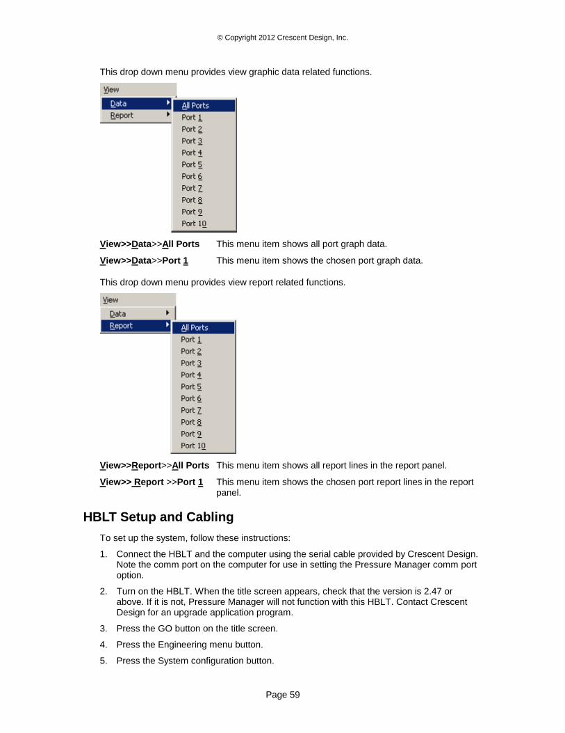
© Copyright 2012 Crescent Design, Inc.
Page 59
This drop down menu provides view graphic data related functions.
View>>Data>>All Ports This menu item shows all port graph data.
View>>Data>>Port 1 This menu item shows the chosen port graph data.
This drop down menu provides view report related functions.
View>>Report>>All Ports This menu item shows all report lines in the report panel.
View>> Report >>Port 1 This menu item shows the chosen port report lines in the report panel.
HBLT Setup and Cabling
To set up the system, follow these instructions:
1. Connect the HBLT and the computer using the serial cable provided by Crescent Design. Note the comm port on the computer for use in setting the Pressure Manager comm port option.
2. Turn on the HBLT. When the title screen appears, check that the version is 2.47 or above. If it is not, Pressure Manager will not function with this HBLT. Contact Crescent Design for an upgrade application program.
3. Press the GO button on the title screen.
4. Press the Engineering menu button.
5. Press the System configuration button.
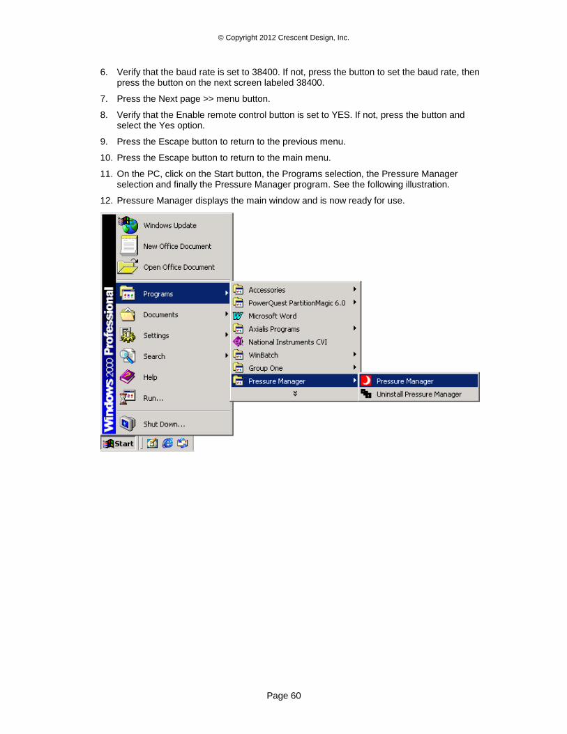
© Copyright 2012 Crescent Design, Inc.
Page 60
6. Verify that the baud rate is set to 38400. If not, press the button to set the baud rate, then press the button on the next screen labeled 38400.
7. Press the Next page >> menu button.
8. Verify that the Enable remote control button is set to YES. If not, press the button and select the Yes option.
9. Press the Escape button to return to the previous menu.
10. Press the Escape button to return to the main menu.
11. On the PC, click on the Start button, the Programs selection, the Pressure Manager selection and finally the Pressure Manager program. See the following illustration.
12. Pressure Manager displays the main window and is now ready for use.
© Copyright 2012 Crescent Design, Inc.
Page 61
Applications
This section describes several common procedures using a step by step approach. Instructions using both mouse and keyboard provide alternate methods to suit an individuals style.
In the following sections, these terms have the following meanings:
1. Click means press and release the left mouse button on the item mentioned.
2. Click and hold means press and hold down the left mouse button on the mentioned item.
3. Drag means move the mouse cursor while holding down the left mouse button.
4. Release means releasing the left mouse button.
5. Type means to press the mentioned keys on the keyboard.
6. ALT-A means to press and hold down the ALT key then pressing the A key. Release both keys together.
Creating a New Test Using the New Button
Starting from the Pressure Profile panel, do the following steps:
1. Click menu Tests>>Test Select or type Alt-T T to open the Test Parameters panel.
2. Click the New button or type ALT-N to start a new HBLT test.
3. Type new test name in the highlighted Test Name control followed by the Enter key. Pressure Manager translates lower case characters to upper case characters and removes any invalid characters. The maximum name length is 11 characters. Pressure Manager also verifies that test name is unique. If the name is already in use, Pressure Manager prompts for a new name.
4. Click the Next button or type ALT-N to select the process type.
5. There are three ways to select the Process type. Click on the control’s arrow buttons to scroll through the test types. Use the Up Arrow key or Down Arrow key to scroll through the test types. Click and hold on the control to open a drop down list. Then, drag the cursor down to the desired process type and release the mouse button.
6. Click the Next button or type ALT-N to select the pressure units.
7. There are three ways to select the Pressure units. Click on the control’s arrow buttons to scroll through the test types. Use the Up Arrow key or Down Arrow key to scroll through the test types. Click and hold on the control to open a drop down list. Then, drag the cursor down to the desired process type and release the mouse button.
8. Click the Next button or type ALT-N to enter the test’s parameters.
9. Pressure Manager highlights all parameters that the selected process type uses and dims the remaining controls. Each control now contains the default parameter settings. Click on each test parameter control to enter a new value by typing the value or clicking the control’s arrow buttons. Pressure Manager coerces each entry to a valid value based on the connected HBLT model type and the selected pressure units.
The Product ID and Engineer ID are option fields. Each field has a maximum of 14 characters. Pressure Manager coerces lower case characters to upper case characters and removes invalid characters.
If this is a Custom process type, use the Custom Value control to enter values into the Custom Targets list box. First, click on desired line until a check mark appears to the left
© Copyright 2012 Crescent Design, Inc.
Page 62
of the value. Then, type the new value into the Custom Value control followed by the Enter key. If the item selected was the first zero entry, continue entering values in the Custom Value control. Pressure Manager automatically increments the list check mark. A zero value sets all remaining values to zero.
If there is a Smart Manifold attached, Pressure Manager displays the Smart Manifold specific values. First, select the Smart Manifold mode. If the mode is single or sequential, Pressure Manager dims the following controls. If the mode is single, Pressure Manager activates the following controls.
10. Click the SAVE button or type ALT-S to close the new test. Pressure Manager sends the test to the connected HBLT. If the HBLT requires a password and it is not entered, Pressure Manager prompts for the password. Pressure Manager then retrieves all the HBLT tests.
11. Choose another function to perform, and then click the Select button or type ALT-S.
Pressing the CANCEL button at any time during this process terminates the creation of the new test and returns the Test Parameters panel to its original state.
Creating a New Test Using the New Test Wizard
Starting from the Pressure Profile panel, do the following steps:
1. Click menu Tests>>Test Select or type Alt-T T to open the Test Parameters panel.
2. Click menu Functions>>New test Wizard or type ALT-F W to open the first wizard panel.
3. Type new test name in the highlighted Test Name control followed by the Enter key. Pressure Manager translates lower case characters to upper case characters and removes any invalid characters. The maximum name length is 11 characters. Pressure Manager also verifies that test name is unique. If the name is already in use, Pressure Manager prompts for a new name.
4. There are three ways to select the Process type. Click on the control’s arrow buttons to scroll through the test types. Use the Up Arrow key or Down Arrow key to scroll through the test types. Click and hold on the control to open a drop down list. Then, drag the cursor down to the desired process type and release the mouse button.
5. There are three ways to select the Pressure units. Click on the control’s arrow buttons to scroll through the test types. Use the Up Arrow key or Down Arrow key to scroll through the test types. Click and hold on the control to open a drop down list. Then, drag the cursor down to the desired process type and release the mouse button.
6. The Product ID and Engineer ID are optional fields. Each field has a maximum of 14 characters. Pressure Manager coerces lower case characters to upper case characters and removes invalid characters.
7. Click the Next button or type ALT-N to move to the next panel.
8. This panel contains the parameters common to all process types. Each control contains the default parameter settings. Click on each test parameter control to enter a new value by typing the value or clicking the control’s arrow buttons. Pressure Manager coerces each entry to a valid value based on the connected HBLT model type and the selected pressure units.
9. Click the Next button or type ALT-N to move to the next panel.
10. This panel is one of five different panels selected by process type. Each panel contains parameters needed by the process type selected on the first panel. Click on each test parameter control to enter a new value by typing the value or clicking the control’s arrow
© Copyright 2012 Crescent Design, Inc.
Page 63
buttons. Pressure Manager coerces each entry to a valid value based on the connected HBLT model type and the selected pressure units.
If this is a Custom process type, use the Custom Value control to enter values into the Custom Targets list box. First, click on desired line until a check mark appears to the left of the value. Then, type the new value into the Custom Value control followed by the Enter key. If the item selected was the first zero entry, continue entering values in the Custom Value control. Pressure Manager automatically increments the list check mark. A zero value sets all remaining values to zero.
11. If there is a Smart Manifold attached, click the Next button or ALT-N to enter the Smart Manifold settings. First, select the Smart Manifold mode. If the mode is single or sequential, Pressure Manager dims the following controls. If the mode is single, Pressure Manager activates the following controls.
12. Click the DONE button or type ALT-D to complete the create test function. Pressure Manager sends the test to the connected HBLT. If the HBLT requires a password and it is not entered, Pressure Manager prompts for the password. Pressure Manager then retrieves all the HBLT tests.
13. Choose another function to perform, and then click the Select button or type ALT-S.
Pressing the CANCEL button at any time during this process terminates the creation of the new test and returns the Test Parameters panel to its original state.
Use the BACK button or type ALT_B to navigate back to previous wizard panels. Change the process type on the first panel. This action changes the selection of the last panel that contains the test parameters special to a process type.
Editing a Test
Starting from the Pressure Profile panel, do the following steps:
1. Click menu Tests>>Test Select or type Alt-T T to open the Test Parameters panel.
2. Click menu Tests or type ALT-T to open the Tests drop down menu.
3. Click on the desired test name listed on the drop down menu. Alternately, type the function key listed to the right of the test name.
4. Click the UPDATE button or type ALT-U to update the current test parameters.
5. Pressure Manager highlights all parameters that this process type uses and dims the remaining controls. Click on each test parameter control to enter a new value by typing the value or clicking the control’s arrow buttons. Pressure Manager coerces each entry to a valid value based on the connected HBLT model type and the selected pressure units.
If this is a Custom process type, use the Custom Value control to enter values into the Custom Targets list box. First, click on desired line until a check mark appears to the left of the value. Then, type the new value into the Custom Value control followed by the Enter key. If the item selected was the first zero entry, continue entering values in the Custom Value control. Pressure Manager automatically increments the list check mark. A zero value sets all remaining values to zero.
6. Click the UPDATE button or type ALT-U to close the edited test. Pressure Manager sends the test to the connected HBLT. If the HBLT requires a password and it is not entered, Pressure Manager prompts for the password. Pressure Manager then retrieves all the HBLT tests.
7. Choose another function to perform, click the Select button or type ALT-S.
Pressing the CANCEL button at any time during this process terminates the creation of the new test and returns the Test Parameters panel to it’s original state.
© Copyright 2012 Crescent Design, Inc.
Page 64
Deleting a Single Test
Starting from the Pressure Profile panel, do the following steps:
1. Click menu Tests>>Test Select or type Alt-T T to open the Test Parameters panel.
2. Click menu Tests or type ALT-T to open the Tests drop down menu.
3. Click on the desired test name listed on the bottom of the drop down menu. Alternately, type the function key listed to the right of the test name.
4. Click the DELETE button or type ALT-D to delete the current test parameters.
5. Pressure Manager displays a confirmation popup window. Choose YES to confirm the
delete or type NO to cancel the delete.
6. If the choice is YES, Pressure Manager deletes the test from the HBLT and retrieves the
remaining tests. If the choice is NO, Pressure Manager does nothing. If the HBLT requires a password and it is not entered, Pressure Manager prompts for the password.
7. Choose another function to perform, click the Select button or type ALT-S.
Deleting many tests using this process is time consuming. Use Tests>>Delete HBLT tests to delete many tests quickly.
Deleting Multiple Tests
Starting from the Pressure Profile panel, do the following steps:
1. Click menu Tests>>Test Select or type Alt-T T to open the Test Parameters panel.
2. Click menu Functions>>Delete HBLT tests or type ALT-T H to open the Delete HBLT tests panel.
3. Pressure Manager displays the current HBLT test names in the list box. There are two ways to select tests to delete. First, click each test name to delete. A check mark appears
to the left of a selected test. Second, click the Select All button or type ALT-A to select all tests. Then click individual names to de-select.
4. When finished selecting tests to delete, click the OK button or type ALT-O to initiate the deletes. If the HBLT requires a password and it is not entered, Pressure Manager prompts for the password.
5. Pressure Manager displays a confirmation popup window. Choose YES to confirm the
deletes or type NO to cancel the deletes.
6. If the choice is YES, Pressure Manager deletes the tests from the HBLT and retrieves any
remaining tests. If the choice is NO, Pressure Manager closes the panel without deleting any tests.
7. Choose another function to perform, click the Select button, or type ALT-S.
Click the CANCEL button or type ALT-C at any time to cancel the delete function without deleting any tests.
Selecting a Test
Starting from the Pressure Profile panel, do the following steps:
1. Click menu Tests>>Test Select or type Alt-T T to open the Test Parameters panel.
2. Click menu Tests or type ALT-T to open the Tests drop down menu.

© Copyright 2012 Crescent Design, Inc.
Page 65
3. Click on the desired test name listed on the drop down menu. Alternately, type the function key listed to the right of the test name.
4. Click the Select button or type ALT-S to select the current test. Pressure Manager closes
the HBLT Test Parameters panel and activates the Start button on the Pressure Profile panel.
Creating a New Script
Starting from the Pressure Profile panel, do the following steps:
1. Click menu Tests>>Script Edit or type Alt-T E to open the Script Editor panel.
2. Click menu File>>New or type ALT-F N to open a new script. Pressure Manager clears any existing script and inserts the following lines: Pressure Manager Data File, Windows 95+, V1:00
UNITS PSI
MODEL 1000
COMPLIANCE: 1
UP RAMP RATE: 250
DOWN RAMP RATE: 250
UP BURST RATE: 50
DOWN BURST RATE: 0
LEAK RATE: 10
LEAK DIP: 0
CUTOFF: 10
FILL AT SPEED: 0.20
END
The units may differ depending upon the default chosen in the configuration panel. Also, the model type changes conditional on the attached HBLT model.
3. IF there is a Smart Manifold attached, Pressure Manager inserts these lines for a new script: Pressure Manager Data File, Windows 95+, V1:00
UNITS PSI
MODEL 500
MANIFOLD MODE PARALLEL
MANIFOLD PURGE RATE: 0.5
MANIFOLD CUTOFF PSI: 10
MANIFOLD TIMEOUT: 10
MANIFOLD COMPLIANCE: 1
MANIFOLD COUNT: 1
COMPLIANCE: 1
UP RAMP RATE: 100.0
DOWN RAMP RATE: 100.0
UP BURST RATE: 200.0
DOWN BURST RATE: 0.0
LEAK RATE: 5.0
LEAK DIP: 0.0
FILL CUTOFF PSI: 10
FILL AT SPEED: 0.20
END
4. There are two methods to enter commands. For both methods, first move the cursor, the line with the yellow background, to the line above the desired insertion point. The first and easiest method is to double click the desired command in the Commands list box. Pressure Manager inserts the command on the line following the cursor line. If
© Copyright 2012 Crescent Design, Inc.
Page 66
the command requires a parameter, type it in and then type the enter key. The second method is to type the Enter key. This opens a new blank script line. Then type in the new command. Pressure Manager completes the command after receiving sufficient characters to identify the command. If the command requires a parameter, type it in and then type the Enter key. Pressure Manager closes the new line and inserts a new blank line. Continue entering commands in this manner. When finished, type the Enter key to close the insert line.
5. After entering and editing the script, click menu File>>Save As or type ALT-F A to open the Save As file selection dialog box. Use the dialog box to select the file path to store the file. The file path consists of the directory and file name.
6. Click the OK button to save the script. Click Cancel to abort the Save As function.
7. Click menu File>>Close or type ALT-F C to close the Script Edit panel and return to the Pressure Profile panel.
Editing a Script
Starting from the Pressure Profile panel, do the following steps:
1. Click menu Tests>>Script Edit or type Alt-T E to open the Script Editor panel.
2. Click menu File>>Open or type ALT-F O to open an existing script. Pressure Manager clears any existing script and opens the Script Open file selection window.
3. Use the file selection window to select the desired script file path.
4. Click the OK button to open the script. Click Cancel to abort the open function.
5. Now edit the script commands. To change a command, first delete the old command and then replace it with a new command. There are two methods to enter commands. For both methods, first move the cursor to the line above the desired insertion point. The first and easiest method is to double click the desired command in the Commands list box. Pressure Manager inserts the command on the line following the cursor line. If the command requires a parameter, type it in and then type the enter key. The second method is to type the Enter key. This opens a new blank script line. Then type in the new command. Pressure Manager completes the command after receiving sufficient characters to identify the command. If the command requires a parameter, type it in and then type the Enter key. Pressure Manager closes the new line and inserts a new blank line. Continue entering commands in this manner. When finished, type the Enter key to close the insert line. To delete a command, move the cursor to the line to delete using the up and down arrow keys or by clicking on the line with the mouse. Then press the Delete key.
6. After entering and editing the script, click menu File>>Save or type ALT-F S to save the
file using it’s original file path. Alternately, click menu File>>Save As or type ALT-F A to open the Save As file selection dialog box. Use the dialog box to select the file path to store the file. The file path consists of the directory and file name.
7. Click menu File>>Close or type ALT-F C to close the Script Edit panel and return to the Pressure Profile panel.
Selecting a Script
Starting from the Pressure Profile panel, do the following steps:
© Copyright 2012 Crescent Design, Inc.
Page 67
1. Click menu Tests>>Script Select or type Alt-T S to open the Test Parameters panel.
2. Click on the desired file name in the list box on the right side of the Script Select panel. Use the scroll bar to navigate up and down the list. Pressure Manager checks the selected script and displays the script text in the script control. If necessary, use the scroll bar to view the entire script.
Pressure Manager displays only valid scripts that the attached HBLT can execute. If there is a flaw in the script or the script model does not match the attached mode, there is no displayed name. Use the Script Edit window to determine and correct the error.
3. After selecting the desired script, click the Select button or type ALT-S to select the script and close the Script Select panel.
4. Click the Start button or type ALT-S to run the script.
Click the Cancel button or type ALT-C any time to close the Script Select panel with no action.
Running the Selected Test or Script
Starting from the Pressure Profile panel, do the following steps:
1. Click the Start button or type ALT-S to start a test or script.
2. When the test completes, Pressure Command activates the Reset button. At this time, the user has the following options:
Save the test data.
Scroll and inspect the strip chart.
Change the strip chart configuration.
Print the test strip chart panel.
View and print the test report.
View and print the test log.
3. When finished with the test, click the Reset button or type ALT-E to reset Pressure
Manager. If not already saved and logging is set to ASK, Pressure Manager prompts for saving the data, report and log information.
4. Go to step 1 to start another test.
To abort a test or script, Press the Stop button or type ALT-S. Pressure Manager activates the
Resume, Escape and OK buttons. For a test, these buttons have the same behavior as their
counterparts on the HBLT LCD screen. Clicking OK ends the test with normal reporting. Escape
escapes from the test with no further action. Resume resumes the test until it ends. Use the same buttons if there is a burst or leak event.
Viewing and Printing a Report
Starting from the Pressure Profile panel, do the following steps:
1. Click menu View>>View Report or type ALT-V R to open the View Report panel.
2. Click menu File>>Save As or type ALT-F A to open the Report Save As file selection window.
3. Enter a file path and click OK. Alternatively, click Cancel to abort.
4. Click menu File>>Print or type ALT-F P to print the report file.
© Copyright 2012 Crescent Design, Inc.
Page 68
5. Click menu File>>Close or type ALT-F C to close the View Report panel.
Viewing and Printing a Report – Smart Manifold
Starting from the Pressure Profile panel, do the following steps:
1. Click menu View>>View Smart Manifold or type ALT-V S to open the Smart Manifold panel.
2. Click menu View>>Report>>All or type ALT-V R A to view the Report for all ports..
3. Click menu View>>Report>>Port 1 or type ALT-V R 1 to view all the Report for port one only. Use the same format to view the report for other ports.
4. Click menu File>>Print>>All or type ALT-F P A to print the Report for all ports..
5. Click menu File>>Print>>Port 1 or type ALT-F P 1 to print all the Report for port one only. Use the same format to print the report for other ports.
6. Click menu File>>Close or type ALT-F C to close the Smart Manifold panel.
Viewing and Printing a Log
Starting from the Pressure Profile panel, do the following steps:
1. Click menu View>>View Log or type ALT-V L to open the View Log panel.
2. Click menu File>>Save As or type ALT-F A to open the Log Save As file selection window.
3. Enter a file path and click OK. Alternatively, click Cancel to abort.
4. Click menu File>>Print or type ALT-F P to print the log file.
5. Click menu File>>Close or type ALT-F C to close the View Log panel.
Capturing Micrometer Readings
Before capturing micrometer data, use the micrometer configuration wizard to configure Pressure Manager for the attached micrometer. The wizard collects all the information for each micrometer type.
Pressure Manager reads the micrometer in two ways. For HBLT native tests, Pressure Manager reads the micrometer when the dwell maintain period ends. For scripts, Pressure Manager reads the micrometer when executing a READ MICROMETER command.
Since there is slight delay in reading the micrometer and interpreting the serial data from the HBLT, you should provide at least a 2 second maintain period. This gives Pressure Manager time to receive and process valid pressure data. To minimize any serial data backlog, use the graph configuration panel to set the data rate to 50 to 20 samples per second. This reduces the amount of serial data processed by Pressure Manager.
The micrometer data is saved using comma-delimited format. Many data analysis programs use this format to import data. Specify that a comma is the delimiting character for programs such as Microsoft Excel. The first line is the column headings text. To ignore headings, specify that the import start on the second line. The headings specify both data type and units.
Viewing and Printing a Micrometer Table
Starting from the Pressure Profile panel, do the following steps:
6. Click menu View>>View Micrometer or type ALT-V M to open the View Micrometer panel.

© Copyright 2012 Crescent Design, Inc.
Page 69
7. Click menu File>>Save As or type ALT-F A to open the Micrometer Save As file selection window.
8. Enter a file path and click OK. Alternatively, click Cancel to abort.
9. Click menu File>>Print or type ALT-F P to print the Micrometer file.
10. Click menu File>>Close or type ALT-F C to close the View Micrometer panel.
© Copyright 2012 Crescent Design, Inc.
Page 70
Messages
This section covers messages emitted by Pressure Manager only. This section does not cover HBLT error messages. See the HBLT manual for messages emitted by the HBLT.
Log Machine State Messages
These messages appear in the log panel. The user has the option of enabling or disabling the display of this message type. The default is to disable this message type.
For these messages, the cause is that the state changed on the data tuple.
Because these messages are for diagnosis only, there is no corrective action.
State: Burst during dwell.
State: Burst during down ramp.
State: Burst during last down ramp.
State: Burst during last down wait.
State: Burst during up ramp.
State: Dwell.
State: Dwell paused.
State: Dwelling.
State: Dwelling paused.
State: Filling product.
State: Last down ramp.
State: Last down ramp paused.
State: Leak dip during dwell.
State: Leak rate during dwell.
State: Ramping down.
State: Ramping down paused.
State: Ramping up.
State: Ramping up paused.
State: Refilling cylinder.
State: Return wait.
State: Return wait paused.
State: Test complete.
Log Input Line Message
This message type appears in the log panel. The user has the option of enabling or disabling the display of this message type. The default is to disable this message.
© Copyright 2012 Crescent Design, Inc.
Page 71
Input: This is text as received from the serial port.
Test Data Message
This message type appears in the log panel. The user has the option of enabling or disabling the display of this message type. The default is to disable this message.
Data: 9999,9999,9999
Location: HBLTMAIN.C -> ProcessTuples().
The numbers represent the translated tuple values. All values are integers. The first number is the current pressure. The second number is the maximum pressure. The third number is the volume data.
This message is primarily a programming development or maintenance tool. But it may be useful in detecting communications problems.
The log panel displays only the selected message types during the test. Pressure Manager discards disabled messages. Therefore, select the message types before running either a test or a script.
Test Results Messages
This message type appears in the report panel. The pressures represented by 99.9 may change format depending on the model and pressure units selected. The elapsed times are the tenth of seconds from the beginning of the current HBLT operation. For instance, a 1.1 value reported during an up ramp operation would be from the time up ramp started. The time is not from the beginning of the test.
Test results: Operator abort (DA) alarm. Max pressure = 99.9, elapsed
time = 0.0.
Cause: HBLT user abort event.
Correction: No action required.
Test results: Operator abort (DA) alarm. Max pressure = 99.9, elapsed
time = 0.0, port=1.
Cause: HBLT user abort event.
Correction: No action required.
Test results: Up burst (DB) alarm. Max pressure = 99.9, Pressure =
99.9, elapsed time = 0.0, event volume 1.11.
Cause: HBLT up burst event.
Correction: No action required.
Test results: Up burst (DB) alarm. Max pressure = 99.9, Pressure =
99.9, elapsed time = 0.0, event volume 1.11, port=1.
Cause: HBLT up burst event.
Correction: No action required.
Test results: Down burst (DC) alarm. Max pressure = 99.9, Pressure =
99.9, elapsed time = 0.0, event volume 1.11.
Cause: HBLT down burst event.
Correction: No action required.
© Copyright 2012 Crescent Design, Inc.
Page 72
Test results: Down burst (DC) alarm. Max pressure = 99.9, Pressure =
99.9, elapsed time = 0.0, event volume 1.11, port=1.
Cause: HBLT down burst event.
Correction: No action required.
Test results: Leak dip (DD) alarm. Max pressure = 99.9, Pressure =
99.9, elapsed time = 0.0, event volume 1.11.
Cause: HBLT leak dip event.
Correction: No action required.
Test results: Leak dip (DD) alarm. Max pressure = 99.9, Pressure =
99.9, elapsed time = 0.0, event volume 1.11, port=1.
Cause: HBLT leak dip event.
Correction: No action required.
Test results: Test finished with no errors (DK) alarm. Max pressure =
99.9, elapsed time = 0.0.
Cause: HBLT test finished without error.
Correction: No action required.
Test results: Test finished with no errors (DK) alarm. Max pressure =
99.9, elapsed time = 0.0, port=1.
Cause: HBLT test finished without error.
Correction: No action required.
Test results: Leak rate (DL) alarm. Max pressure = 99.9, Pressure =
99.9, elapsed time = 0.0, event volume 1.11.
Cause: HBLT leak rate event.
Correction: No action required.
99.9, elapsed time = 0.0, event volume 1.11, port=1.
Cause: HBLT leak rate event.
Correction: No action required.
Test results: Test aborted due to bad calibration (DZ).
Cause: HBLT not calibrated event.
Correction: Calibrate the HBLT prior to running a test or script.
Test results: Script completed.
Cause: The script completed.
Correction: No action required.
Log Status Messages
This message type appears in the log panel. Pressure Manager always displays this message type.
Status: Data capture off.
Cause: This message announces that the data capture is off.
Correction: No action required.
© Copyright 2012 Crescent Design, Inc.
Page 73
Status: Data capture on.
Cause: This message announces that the data capture is on.
Correction: No action required.
Status: Displaying test data from <file name>.
Cause: This message announces that Pressure Manager is displaying previously saved data.
Correction: No action required.
Status: Idle.
Cause: This message announces that Pressure Manager is idle.
Correction: No action required.
Status: No script or test selected.
Cause: This message announces that there is no test or script selected.
Correction: No action required.
Status: Operator Escaped process.
Cause: This message announces that the operator pressed the ESCAPE button.
Correction: No action required.
Status: Operator pressed OK.
Cause: This message announces that the operator pressed the OK button.
Correction: No action required.
Status: Operator stopped process.
Cause: This message announces that the operator stopped the current process.
Correction: No action required.
Status: Ready for operation.
Cause: This message announces that Pressure Manager is ready for operation.
Correction: No action required.
Status: Ready to run HBLT test <test name>.
Cause: This message announces that Pressure Manager is ready to run a HBLT test.
Correction: No action required.
Status: Ready to run script <script name>.
Cause: This message announces that Pressure Manager is ready to run a script.
Correction: No action required.
Status: Remote delete OK.
Cause: This message announces that the remote delete test command completed successfully. That is the HBLT deleted a test specified by Pressure Manager with no errors.
Correction: No action required.
© Copyright 2012 Crescent Design, Inc.
Page 74
Status: Remote import OK.
Cause: This message announces that the remote test import command completed successfully. That is the HBLT received a test from Pressure Manager with no errors.
Correction: No action required.
Status: Remote retrieve OK.
Cause: This message announces that the remote test retrieve command completed successfully. That is Pressure Manager received a test from the HBLT with no errors.
Correction: No action required.
Status: Remote setup OK.
Cause: This message announces that the remote setup command completed successfully.
Correction: No action required.
Status: Resuming operation.
Cause: This message announces that Pressure Manager is resuming operation.
Correction: No action required.
Status: Running test <name> lot number <lot ID> operator <oper ID>.
Cause: This message announces that Pressure Manager is starting a test.
Correction: No action required.
Status: Script setup OK.
Cause: This message announces that Script setup is OK.
Correction: No action required.
Status: Working offline.
Cause: This message announces that Pressure Manager is working in offline mode.
Correction: No action required.
Log Error Messages
This message type appears in the log panel. Pressure Manager always displays this message type.
Error: ? command failed with a Acknowledge Format error.
Cause: The HBLT NAK format was wrong.
Action: Check the serial cable to insure the connections are tight. If the problem persists, contact Crescent Design, Inc. and report the error.
Error: ? command failed with a Command error.
Cause: The HBLT NAKed the command “?”. The HBLT was not on the proper screen.
Action: Check the serial cable to insure the connections are tight. If the problem persists, contact Crescent Design, Inc. and report the error.
© Copyright 2012 Crescent Design, Inc.
Page 75
Error: ? command failed with a Non-numeric error.
Cause: The HBLT NAKed the command “?” because there was a non-numeric character in the parameter.
Action: Check the serial cable to insure the connections are tight. If the problem persists, contact Crescent Design, Inc. and report the error.
Error: ? command failed with a Maximum Exceeded error.
Cause: The HBLT NAKed the command “?” because the parameter value exceeds the maximum for this command given the model type and pressure units.
Action: Check the serial cable to insure the connections are tight. If the problem persists, contact Crescent Design, Inc. and report the error.
Error: ? command failed with a Minimum Exceeded error.
Cause: The HBLT NAKed the command “?” because the parameter value exceeds the minimum for this command given the model type and pressure units.
Action: Check the serial cable to insure the connections are tight. If the problem persists, contact Crescent Design, Inc. and report the error.
Error: ? command failed with a Timeout error.
Cause: The HBLT NAKed the command “?” because the full text of the command was not received within the allotted time.
Action: Check the serial cable to insure the connections are tight. If the problem persists, contact Crescent Design, Inc. and report the error.
Error: Abort command failed with a Invalid error.
Cause: There was a serial transmission error, the HBLT screen is incorrect, or there is a programmer error.
Correction: Check the serial cable to insure the connections are tight. Insure the HBLT is on the correct screen. If the problem persists, contact Crescent Design, Inc. and report the error.
Error: Abort script timeout error.
Cause: There was a serial transmission error, the HBLT is off or on the wrong screen, or there is a programmer error
Correction: Check the serial cable to insure the connections are tight. Check the HBLT to make sure it is on the proper screen. If the problem persists, contact Crescent Design, Inc. and report the error.
Error: ACK error.
Cause: There was a serial transmission error or there is a programmer error.
Correction: Check the serial cable to insure the connections are tight. If the problem persists, contact Crescent Design, Inc. and report the error.
Error: ATM timeout error.
Cause: There was a serial transmission error, the HBLT is off or on the wrong screen, or there is a programmer error
Correction: Check the serial cable to insure the connections are tight. Check the HBLT to make sure it is on the proper screen. If the problem persists, contact Crescent Design, Inc. and report the error.
© Copyright 2012 Crescent Design, Inc.
Page 76
Error: BAR timeout error.
Cause: There was a serial transmission error, the HBLT is off or on the wrong screen, or there is a programmer error
Correction: Check the serial cable to insure the connections are tight. Check the HBLT to make sure it is on the proper screen. If the problem persists, contact Crescent Design, Inc. and report the error.
Error: Configuration – Failed to write default PERSDATA.CFG file.
Cause: The system failed to open a file to write the PERSDATA.CFG file. This file contains the persistent setting that must survive between program executions.
Correction: The only known cause for this error is a full disk. Check the disk to insure that it is not full.
Error: Configuration – Failed to write PERSDATA.CFG file.
Cause: The system failed to open a file to write the PERSDATA.CFG file. This file contains the persistent setting that must survive between program executions.
Correction: The only known cause for this error is a full disk. Check the disk to insure that it is not full.
Error: Configuration – Invalid ATM Max Record.
Cause: The ATM_MAX= record in PERSDATA.CFG is damaged.
Correction: Most likely someone edited the file. Pressure Manager creates and updates this file to hold the persistent settings the operator selects. To fix the problem,
select the Configure>>Graph Settings menu item. When the panel
appears, click the OK button. This forces Pressure Manager to overwrite the damaged PERSDATA.CFG with a new PERSDATA.CFG file.
Error: Configuration – Invalid BAR Max Record.
Cause: The BAR_MAX= record in PERSDATA.CFG is damaged.
Correction: Most likely someone edited the file. Pressure Manager creates and updates this file to hold the persistent settings the operator selects. To fix the problem,
select the Configure>>Graph Settings menu item. When the panel
appears, click the OK button. This forces Pressure Manager to overwrite the damaged PERSDATA.CFG with a new PERSDATA.CFG file.
Error: Configuration – Invalid Config Record.
Cause: One of the records in PERSDATA.CFG is damaged.
Correction: Most likely someone edited the file. Pressure Manager creates and updates this file to hold the persistent settings the operator selects. To fix the problem,
select the Configure>>Graph Settings menu item. When the panel
appears, click the OK button. This forces Pressure Manager to overwrite the damaged PERSDATA.CFG with a new PERSDATA.CFG file.
Error: Configuration – Invalid Data Rate Record.
Cause: The DATA_RATE= record in PERSDATA.CFG is damaged.
Correction: Most likely someone edited the file. Pressure Manager creates and updates this file to hold the persistent settings the operator selects. To fix the problem,
select the Configure>>Graph Settings menu item. When the panel
appears, click the OK button. This forces Pressure Manager to overwrite the damaged PERSDATA.CFG with a new PERSDATA.CFG file.
© Copyright 2012 Crescent Design, Inc.
Page 77
Error: Configuration – Invalid Default Pressure Units Record.
Cause: The DEFAULT_PRESSURE_UNITS= record in PERSDATA.CFG is damaged.
Correction: Most likely someone edited the file. Pressure Manager creates and updates this file to hold the persistent settings the operator selects. To fix the problem,
select the Configure>>Graph Settings menu item. When the panel
appears, click the OK button. This forces Pressure Manager to overwrite the damaged PERSDATA.CFG with a new PERSDATA.CFG file.
Error: Configuration – Invalid DISPLAY_NEG_PRESS Record.
Cause: The DISPLAY_NEG_PRESS = record in PERSDATA.CFG is damaged.
Correction: Most likely someone edited the file. Pressure Manager creates and updates this file to hold the persistent settings the operator selects. To fix the problem,
select the Configure>>Graph Settings menu item. When the panel
appears, click the OK button. This forces Pressure Manager to overwrite the damaged PERSDATA.CFG with a new PERSDATA.CFG file.
Error: Configuration – Invalid DISPLAY_SUMMARY Record.
Cause: The DISPLAY_SUMMARY = record in PERSDATA.CFG is damaged.
Correction: Most likely someone edited the file. Pressure Manager creates and updates this file to hold the persistent settings the operator selects. To fix the problem,
select the Configure>>Graph Settings menu item. When the panel
appears, click the OK button. This forces Pressure Manager to overwrite the damaged PERSDATA.CFG with a new PERSDATA.CFG file.
Error: Configuration – Invalid KPA Max Record.
Cause: The KPA_MAX= record in PERSDATA.CFG is damaged.
Correction: Most likely someone edited the file. Pressure Manager creates and updates this file to hold the persistent settings the operator selects. To fix the problem,
select the Configure>>Graph Settings menu item. When the panel
appears, click the OK button. This forces Pressure Manager to overwrite the damaged PERSDATA.CFG with a new PERSDATA.CFG file.
Error: Configuration – Invalid MAX_PRESS_TRACE Record.
Cause: The MAX_PRESS_TRACE= record in PERSDATA.CFG is damaged.
Correction: Most likely someone edited the file. Pressure Manager creates and updates this file to hold the persistent settings the operator selects. To fix the problem,
select the Configure>>Graph Settings menu item. When the panel
appears, click the OK button. This forces Pressure Manager to overwrite the damaged PERSDATA.CFG with a new PERSDATA.CFG file.
Error: Configuration – Invalid PSI Max Record.
Cause: The PSI_MAX= record in PERSDATA.CFG is damaged.
Correction: Most likely someone edited the file. Pressure Manager creates and updates this file to hold the persistent settings the operator selects. To fix the problem,
select the Configure>>Graph Settings menu item. When the panel
appears, click the OK button. This forces Pressure Manager to overwrite the damaged PERSDATA.CFG with a new PERSDATA.CFG file.
© Copyright 2012 Crescent Design, Inc.
Page 78
Error: Configuration – Invalid VOL SCALE Record.
Cause: The VOL_SCALE= record in PERSDATA.CFG is damaged.
Correction: Most likely someone edited the file. Pressure Manager creates and updates this file to hold the persistent settings the operator selects. To fix the problem,
select the Configure>>Graph Settings menu item. When the panel
appears, click the OK button. This forces Pressure Manager to overwrite the damaged PERSDATA.CFG with a new PERSDATA.CFG file.
Error: Configuration – Invalid VOLUME_TRACE Record.
Cause: The VOLUME_TRACE= record in PERSDATA.CFG is damaged.
Correction: Most likely someone edited the file. Pressure Manager creates and updates this file to hold the persistent settings the operator selects. To fix the problem,
select the Configure>>Graph Settings menu item. When the panel
appears, click the OK button. This forces Pressure Manager to overwrite the damaged PERSDATA.CFG with a new PERSDATA.CFG file.
Error: Configuration – Invalid Volume Type Record.
Cause: The VOLUME_TYPE= record in PERSDATA.CFG is damaged.
Correction: Most likely someone edited the file. Pressure Manager creates and updates this file to hold the persistent settings the operator selects. To fix the problem,
select the Configure>>Graph Settings menu item. When the panel
appears, click the OK button. This forces Pressure Manager to overwrite the damaged PERSDATA.CFG with a new PERSDATA.CFG file.
Error: Configuration – Invalid Window Time Record.
Cause: The WINDOW_TIME= record in PERSDATA.CFG is damaged.
Correction: Most likely someone edited the file. Pressure Manager creates and updates this file to hold the persistent settings the operator selects. To fix the problem,
select the Configure>>Graph Settings menu item. When the panel
appears, click the OK button. This forces Pressure Manager to overwrite the damaged PERSDATA.CFG with a new PERSDATA.CFG file.
Error: compliance timeout error.
Cause: There was a serial transmission error, the HBLT is off or on the wrong screen, or there is a programmer error
Correction: Check the serial cable to insure the connections are tight. Check the HBLT to make sure it is on the proper screen. If the problem persists, contact Crescent Design, Inc. and report the error.
Error: Cstate machine state flag error.
Cause: There was a serial transmission error or there is a programmer error.
Correction: Check the serial cable to insure the connections are tight. If the problem persists, contact Crescent Design, Inc. and report the error.,
Error: cutoff timeout error.
Cause: There a serial transmission error, the HBLT is off or on the wrong screen, or there is a programmer error
Correction: Check the serial cable to insure the connections are tight. Check the HBLT to make sure it is on the proper screen. If the problem persists, contact Crescent Design, Inc. and report the error.
© Copyright 2012 Crescent Design, Inc.
Page 79
Error: Cycle+1 timeout error.
Cause: There was a serial transmission error, the HBLT screen is incorrect, or there is a programmer error.
Correction: Check the serial cable to insure the connections are tight. Insure the HBLT is on the correct screen. If the problem persists, contact Crescent Design, Inc. and report the error.
Error: Data stream error.
Cause: There was a serial transmission error or there is a programmer error.
Correction: Check the serial cable to insure the connections are tight. If the problem persists, contact Crescent Design, Inc. and report the error.,
Error: delay timeout error.
Cause: A script delay command failed to complete. There was a serial transmission error or there is a programmer error.
Correction: Check the serial cable to insure the connections are tight. If the problem persists, contact Crescent Design, Inc. and report the error.,
Error: Deliver Volume timeout error.
Cause: There was a serial transmission error, the HBLT is off or on the wrong screen, or there is a programmer error.
Correction: Check the serial cable to insure the connections are tight. Check the HBLT to make sure it is on the proper screen. If the problem persists, contact Crescent Design, Inc. and report the error.
Error: down burst rate timeout error.
Cause: There was a serial transmission error, the HBLT is off or on the wrong screen, or there is a programmer error
Correction: Check the serial cable to insure the connections are tight. Check the HBLT to make sure it is on the proper screen. If the problem persists, contact Crescent Design, Inc. and report the error.
Error: down ramp rate timeout error.
Cause: There was a serial transmission error, the HBLT is off or on the wrong screen, or there is a programmer error.
Correction: Check the serial cable to insure the connections are tight. Check the HBLT to make sure it is on the proper screen. If the problem persists, contact Crescent Design, Inc. and report the error.
Error: Download failed to allocate buffer space.
Cause: Pressure Manager failed to allocate memory.
Correction: This is a system error. If the problem persists, contact Crescent Design, Inc. and report the error.
Error: Download failed to open a disk file.
Cause: Pressure Manager failed to open a test stored on the disk file.
Correction: The most likely cause is that the file is on removable media and the operator removed the media. Otherwise, this is a programmer error. If the problem persists, contact Crescent Design, Inc. and report the error.
© Copyright 2012 Crescent Design, Inc.
Page 80
Error: Download test canceled.
Cause: The operator choose to cancel the password request panel when downloading a test.
Correction: Enter the HBLT password when prompted during a test download.
Error: Download test timed out.
Cause: There was a serial transmission error, the HBLT is off or on the wrong screen, or there is a programmer error.
Correction: Check the serial cable to insure the connections are tight. Check the HBLT to make sure it is on the proper screen. If the problem persists, contact Crescent Design, Inc. and report the error.
Error: Error in summary line at: <text>.
Cause: The Smart Manifold summary data is corrupt or the file selected is not a summary data file.
Correction: Check the summary file for damage.
Error: end script timeout error.
Cause: There was a serial transmission error, the HBLT screen is incorrect, or there is a programmer error.
Correction: Check the serial cable to insure the connections are tight. Insure the HBLT is on the correct screen. If the problem persists, contact Crescent Design, Inc. and report the error.
Error: Error parsing a DA alarm. Max pressure = 99.9, elapsed time =
0.0.
Cause: There was a serial transmission error or there is a programmer error.
Correction: Check the serial cable to insure the connections are tight. If the problem persists, contact Crescent Design, Inc. and report the error.,
Error: Error parsing a DB alarm. Max pressure = 99.9, Pressure =
99.9, elapsed time = 0.0, event volume 1.11.
Cause: There was a serial transmission error or there is a programmer error.
Correction: Check the serial cable to insure the connections are tight. If the problem persists, contact Crescent Design, Inc. and report the error.
Error: Error parsing a DC alarm. Max pressure = 99.9, Pressure =
99.9, elapsed time = 0.0, event volume 1.11.
Cause: There was a serial transmission error or there is a programmer error.
Correction: Check the serial cable to insure the connections are tight. If the problem persists, contact Crescent Design, Inc. and report the error.
Error: Error parsing a DD alarm. Max pressure = 99.9, Pressure =
99.9, elapsed time = 0.0, event volume 1.11.
Cause: There was a serial transmission error or there is a programmer error.
Correction: Check the serial cable to insure the connections are tight. If the problem persists, contact Crescent Design, Inc. and report the error.
© Copyright 2012 Crescent Design, Inc.
Page 81
Error: Error parsing a DK alarm. Max pressure = 99.9, elapsed time =
0.0.
Cause: There was a serial transmission error or there is a programmer error.
Correction: Check the serial cable to insure the connections are tight. If the problem persists, contact Crescent Design, Inc. and report the error.,
Error: Error parsing a DL alarm. Max pressure = 99.9, elapsed time =
0.0, event volume 1.11.
Cause: There was a serial transmission error or there is a programmer error.
Correction: Check the serial cable to insure the connections are tight. If the problem persists, contact Crescent Design, Inc. and report the error.,
Error: Faild to allocate memory for script line.
Cause: This is a programmer error.
Correction: Contact Crescent Design, Inc. and report the error.
Error: Failed to download test.
Cause: There was a serial transmission error, the HBLT is off or on the wrong screen, or there is a programmer error. The HBLT may have detected one or more of the following errors: no test name, bad parse, bad scrutenize, no pressure units line, no process type line, save failed, timeout, HBLT error, input buffer overrun, or invalid password.
Correction: Check the serial cable to insure the connections are tight. Check the HBLT to make sure it is on the proper screen. If the problem persists, contact Crescent Design, Inc. and report the error.
Error: Fill At Speed command failed with a Invalid error.
Cause: There was a serial transmission error, the HBLT screen is incorrect, or there is a programmer error.
Correction: Check the serial cable to insure the connections are tight. Insure the HBLT is on the correct screen. If the problem persists, contact Crescent Design, Inc. and report the error.
Error: Fill At Speed command failed with a Maximum Exceeded error.
Cause: There was a serial transmission error or there is a programmer error.
Correction: Check the serial cable to insure the connections are tight. If the problem persists, contact Crescent Design, Inc. and report the error.
Error: Fill At Speed command failed with a Minimum Exceeded error.
Cause: There was a serial transmission error or there is a programmer error.
Correction: Check the serial cable to insure the connections are tight. If the problem persists, contact Crescent Design, Inc. and report the error.
Error: Fill At Speed command failed with a Non-numeric error.
Cause: There was a serial transmission error or there is a programmer error.
Correction: Check the serial cable to insure the connections are tight. If the problem persists, contact Crescent Design, Inc. and report the error.
© Copyright 2012 Crescent Design, Inc.
Page 82
Error: Fill At Speed command failed with a Timeout error.
Cause: There was a serial transmission error, the HBLT is not on the correct screen, or there is a programmer error.
Correction: Check the serial cable to insure the connections are tight. Insure that the HBLT is on the correct screen. If the problem persists, contact Crescent Design, Inc. and report the error.
Error: fill at speed timeout error.
Cause: There was a serial transmission error, the HBLT is off or on the wrong screen, or there is a programmer error.
Correction: Check the serial cable to insure the connections are tight. Check the HBLT to make sure it is on the proper screen. If the problem persists, contact Crescent Design, Inc. and report the error.
Error: Get Smart Manifold Input timeout error.
Cause: There was a serial transmission error, the HBLT is off or on the wrong screen, or there is a programmer error.
Correction: Check the serial cable to insure the connections are tight. Check the HBLT to make sure it is on the proper screen. If the problem persists, contact Crescent Design, Inc. and report the error.
Error: Get Smart Manifold status parse error.
Cause: There was a serial transmission error, the HBLT is off or on the wrong screen, or there is a programmer error.
Correction: Check the serial cable to insure the connections are tight. Check the HBLT to make sure it is on the proper screen. If the problem persists, contact Crescent Design, Inc. and report the error.
Error: Get Smart Manifold status timed out.
Cause: There was a serial transmission error, the HBLT is off or on the wrong screen, or there is a programmer error.
Correction: Check the serial cable to insure the connections are tight. Check the HBLT to make sure it is on the proper screen. If the problem persists, contact Crescent Design, Inc. and report the error.
Error: Get Smart Manifold test results parse error.
Cause: There was a serial transmission error, the HBLT is off or on the wrong screen, or there is a programmer error.
Correction: Check the serial cable to insure the connections are tight. Check the HBLT to make sure it is on the proper screen. If the problem persists, contact Crescent Design, Inc. and report the error.
Error: Group test failed to find a test.
Cause: Someone deleted a test referenced in a group test.
Correction: Edit the group test to remove the offending test. Alternatively, create a new test replacing the missing test.
© Copyright 2012 Crescent Design, Inc.
Page 83
Error: Group test found a nested group test.
Cause: Someone created a group test with the same name as a test referenced in this group test.
Correction: Edit the group test to remove the offending test. Alternatively, create a new test replacing the missing test.
Error: Group test found a pressure units conflict.
Cause: Someone changed the pressure units on a test referenced by a group test. All tests within a group test must use the same pressure units.
Correction: Find the offending test and change the pressure units to match the pressure units in all the other group test.
Error: Group test found a Smart Manifold mode conflict.
Cause: Someone changed the Smart Manifold mode on a test referenced by a group test. All tests within a group test must use the same Smart Manifold mode.
Correction: Find the offending test and change the Smart Manifold mode to match the Smart Manifold mode in all the other group test.
Error: Group test has no tests listed.
Cause: The HBLT found that a group test has no tests listed. This is a software error.
Correction: Create a new group test to replace the damaged group test. Contact Crescent Design, Inc. and report this error.
Error: HBLT ran out of water.
Cause: There are several causes for this error. This error means the HBLT piston activated the exhaust limit switch. See the corrections for causes and fixes.
Correction: Check the HBLT for correct purging. A large air bubble requires compression that uses some of the piston stroke. Check to see if the product or fixture is leaking. If the HBLT cannot reach the target pressure because of a leak, the HBLT continues to run until consuming all the water. If using a Smart Manifold with vacuum targets, make sure that a script does a fill after a negative target. Do this even if the new target pressure is zero PSI.
Error: HBLT test adaptive compliance count error.
Cause: There was a serial transmission error or there is a programmer error.
Correction: Check the serial cable to insure the connections are tight. If the problem persists, contact Crescent Design, Inc. and report the error.,
Error: HBLT test adaptive compliance error.
Cause: There was a serial transmission error or there is a programmer error.
Correction: Check the serial cable to insure the connections are tight. If the problem persists, contact Crescent Design, Inc. and report the error.,
Error: HBLT test compliance parse error.
Cause: There was a serial transmission error or there is a programmer error.
Correction: Check the serial cable to insure the connections are tight. If the problem persists, contact Crescent Design, Inc. and report the error.,
© Copyright 2012 Crescent Design, Inc.
Page 84
Error: HBLT test creation date parse error.
Cause: There was a serial transmission error or there is a programmer error.
Correction: Check the serial cable to insure the connections are tight. If the problem persists, contact Crescent Design, Inc. and report the error.,
Error: HBLT test cycle delay parse error.
Cause: There was a serial transmission error or there is a programmer error.
Correction: Check the serial cable to insure the connections are tight. If the problem persists, contact Crescent Design, Inc. and report the error.,
Error: HBLT test cycles parse error.
Cause: There was a serial transmission error or there is a programmer error.
Correction: Check the serial cable to insure the connections are tight. If the problem persists, contact Crescent Design, Inc. and report the error.,
Error: HBLT test down burst rate parse error.
Cause: There was a serial transmission error or there is a programmer error.
Correction: Check the serial cable to insure the connections are tight. If the problem persists, contact Crescent Design, Inc. and report the error.,
Error: HBLT test down rate parse error.
Cause: There was a serial transmission error or there is a programmer error.
Correction: Check the serial cable to insure the connections are tight. If the problem persists, contact Crescent Design, Inc. and report the error.,
Error: HBLT test dwell time parse error.
Cause: There was a serial transmission error or there is a programmer error.
Correction: Check the serial cable to insure the connections are tight. If the problem persists, contact Crescent Design, Inc. and report the error.,
Error: HBLT test edit date parse error.
Cause: There was a serial transmission error or there is a programmer error.
Correction: Check the serial cable to insure the connections are tight. If the problem persists, contact Crescent Design, Inc. and report the error.,
Error: HBLT test engineer ID parse error.
Cause: There was a serial transmission error or there is a programmer error.
Correction: Check the serial cable to insure the connections are tight. If the problem persists, contact Crescent Design, Inc. and report the error.,
Error: HBLT test Smart Manifold mode parse error.
Cause: There was a serial transmission error or there is a programmer error.
Correction: Check the serial cable to insure the connections are tight. If the problem persists, contact Crescent Design, Inc. and report the error.,
Error: HBLT test fill speed parse error.
Cause: There was a serial transmission error or there is a programmer error.
Correction: Check the serial cable to insure the connections are tight. If the problem persists, contact Crescent Design, Inc. and report the error.,
© Copyright 2012 Crescent Design, Inc.
Page 85
Error: HBLT test find port cutoff psi parse error.
Cause: There was a serial transmission error or there is a programmer error.
Correction: Check the serial cable to insure the connections are tight. If the problem persists, contact Crescent Design, Inc. and report the error.,
Error: HBLT test find port rate parse error.
Cause: There was a serial transmission error or there is a programmer error.
Correction: Check the serial cable to insure the connections are tight. If the problem persists, contact Crescent Design, Inc. and report the error.,
Error: HBLT test find port timeout parse error.
Cause: There was a serial transmission error or there is a programmer error.
Correction: Check the serial cable to insure the connections are tight. If the problem persists, contact Crescent Design, Inc. and report the error.,
Error: HBLT test group test name parse error.
Cause: There was a serial transmission error or there is a programmer error.
Correction: Check the serial cable to insure the connections are tight. If the problem persists, contact Crescent Design, Inc. and report the error.,
Error: HBLT test incremental pressure parse error.
Cause: There was a serial transmission error or there is a programmer error.
Correction: Check the serial cable to insure the connections are tight. If the problem persists, contact Crescent Design, Inc. and report the error.,
Error: HBLT test initial pressure parse error.
Cause: There was a serial transmission error or there is a programmer error.
Correction: Check the serial cable to insure the connections are tight. If the problem persists, contact Crescent Design, Inc. and report the error.,
Error: HBLT test leak dip parse error.
Cause: There was a serial transmission error or there is a programmer error.
Correction: Check the serial cable to insure the connections are tight. If the problem persists, contact Crescent Design, Inc. and report the error.,
Error: HBLT test leak rate parse error.
Cause: There was a serial transmission error or there is a programmer error.
Correction: Check the serial cable to insure the connections are tight. If the problem persists, contact Crescent Design, Inc. and report the error.,
Error: HBLT test maintain time parse error.
Cause: There was a serial transmission error or there is a programmer error.
Correction: Check the serial cable to insure the connections are tight. If the problem persists, contact Crescent Design, Inc. and report the error.,
Error: HBLT test max pressure parse error.
Cause: There was a serial transmission error or there is a programmer error.
Correction: Check the serial cable to insure the connections are tight. If the problem persists, contact Crescent Design, Inc. and report the error.,
© Copyright 2012 Crescent Design, Inc.
Page 86
Error: HBLT test name parse error.
Cause: There was a serial transmission error or there is a programmer error.
Correction: Check the serial cable to insure the connections are tight. If the problem persists, contact Crescent Design, Inc. and report the error.,
Error: HBLT test pressure units parse error.
Cause: There was a serial transmission error or there is a programmer error.
Correction: Check the serial cable to insure the connections are tight. If the problem persists, contact Crescent Design, Inc. and report the error.,
Error: HBLT test process type parse error.
Cause: There was a serial transmission error or there is a programmer error.
Correction: Check the serial cable to insure the connections are tight. If the problem persists, contact Crescent Design, Inc. and report the error.,
Error: HBLT test product id parse error.
Cause: There was a serial transmission error or there is a programmer error.
Correction: Check the serial cable to insure the connections are tight. If the problem persists, contact Crescent Design, Inc. and report the error.,
Error: HBLT test repeat cycles parse error.
Cause: There was a serial transmission error or there is a programmer error.
Correction: Check the serial cable to insure the connections are tight. If the problem persists, contact Crescent Design, Inc. and report the error.,
Error: HBLT test return pressure parse error.
Cause: There was a serial transmission error or there is a programmer error.
Correction: Check the serial cable to insure the connections are tight. If the problem persists, contact Crescent Design, Inc. and report the error.,
Error: HBLT test target number parse error.
Cause: There was a serial transmission error or there is a programmer error.
Correction: Check the serial cable to insure the connections are tight. If the problem persists, contact Crescent Design, Inc. and report the error.,
Error: HBLT test target pressure parse error.
Cause: There was a serial transmission error or there is a programmer error.
Correction: Check the serial cable to insure the connections are tight. If the problem persists, contact Crescent Design, Inc. and report the error.,
Error: HBLT test up burst rate parse error.
Cause: There was a serial transmission error or there is a programmer error.
Correction: Check the serial cable to insure the connections are tight. If the problem persists, contact Crescent Design, Inc. and report the error.,
Error: HBLT test up rate parse error.
Cause: There was a serial transmission error or there is a programmer error.
Correction: Check the serial cable to insure the connections are tight. If the problem persists, contact Crescent Design, Inc. and report the error.,
© Copyright 2012 Crescent Design, Inc.
Page 87
Error: HBLT type too long error.
Cause: There was a serial transmission error or there is a programmer error.
Correction: Check the serial cable to insure the connections are tight. If the problem persists, contact Crescent Design, Inc. and report the error.
Error: Header label error.
Cause: There was a serial transmission error or there is a programmer error.
Correction: Check the serial cable to insure the connections are tight. If the problem persists, contact Crescent Design, Inc. and report the error.,
Error: intake limit switch alarm.
Cause: The HBLT piston activated the intake limit switch.
Correction: Make sure the HBLT is properly purged and calibrated. Check the position of the intake limit switch.
Error: Invalid alarm error.
Cause: There was a serial transmission error or there is a programmer error.
Correction: Check the serial cable to insure the connections are tight. If the problem persists, contact Crescent Design, Inc. and report the error.
Error: Invalid data header.
Cause: The most likely cause is that someone edited the data file. This file may not be a Pressure Manager data file.
Correction: Compare the data file header with a known good data header and correct the error.
Error: Invalid process name alarm.
Cause: Pressure Manager directed the HBLT to execute a test that did not exist. There was a serial transmission error, a person deleted the test after Pressure Manager fetched the tests, or there is a programmer error.
Correction: First, check to verify that the test exists on the HBLT. Check the serial cable to insure the connections are tight. If the problem persists, contact Crescent Design, Inc. and report the error.
Error: KPA timeout error.
Cause: There was a serial transmission error, the HBLT is off or on the wrong screen, or there is a programmer error
Correction: Check the serial cable to insure the connections are tight. Check the HBLT to make sure it is on the proper screen. If the problem persists, contact Crescent Design, Inc. and report the error.
Error: leak dip timeout error.
Cause: There was a serial transmission error, the HBLT is off or on the wrong screen, or there is a programmer error
Correction: Check the serial cable to insure the connections are tight. Check the HBLT to make sure it is on the proper screen. If the problem persists, contact Crescent Design, Inc. and report the error.
© Copyright 2012 Crescent Design, Inc.
Page 88
Error: leak rate timeout error.
Cause: There was a serial transmission error, the HBLT is off or on the wrong screen, or there is a programmer error
Correction: Check the serial cable to insure the connections are tight. Check the HBLT to make sure it is on the proper screen. If the problem persists, contact Crescent Design, Inc. and report the error.
Error: Machine type parse error.
Cause: There was a serial transmission error or there is a programmer error.
Correction: Check the serial cable to insure the connections are tight. If the problem persists, contact Crescent Design, Inc. and report the error.,
Error: maintain timeout error.
Cause: A script maintain command failed to complete. There was a serial transmission error or there is a programmer error.
Correction: Check the serial cable to insure the connections are tight. If the problem persists, contact Crescent Design, Inc. and report the error.,
Error: message timeout error.
Cause: There was a serial transmission error, the HBLT is off or on the wrong screen, or there is a programmer error
Correction: Check the serial cable to insure the connections are tight. Check the HBLT to make sure it is on the proper screen. If the problem persists, contact Crescent Design, Inc. and report the error.
Error: Motor drive electronics overtemp alarm.
Cause: The HBLT drive electronics are too hot.
Correction: Check the HBLT circuit board fan for proper operation.
Error: Motor encoder fault alarm.
Cause: The HBLT encoder faulted.
Correction: Check the HBLT for proper operation.
Error: Motor stall alarm.
Cause: The HBLT motor stalled. An alternate cause may be a fault encoder.
Correction: Check the HBLT encoder for proper operation. The HBLT detects a stall by sensing that the encoder is not turning while current is applied to the motor for a period 4 seconds.
Error: NAK error.
Cause: There was a serial transmission error or there is a programmer error.
Correction: Check the serial cable to insure the connections are tight. If the problem persists, contact Crescent Design, Inc. and report the error.
Error: Over pressure alarm.
Cause: The HBLT exceeded its maximum pressure.
Correction: Check the HBLT for proper operation.
© Copyright 2012 Crescent Design, Inc.
Page 89
Error: Over temperature alarm.
Cause: The HBLT exceeded its maximum temperature.
Correction: Check the HBLT for proper operation.
Error: Parse buffer overflow alarm.
Cause: The HBLT exceeded an internal buffer limit while in the product fill mode.
Correction: This is a programmer error. Contact Crescent Design, Inc. to report the error.
Error: prepare for no vacuum timeout error.
Cause: There was a serial transmission error, the HBLT is off or on the wrong screen, or there is a programmer error
Correction: Check the serial cable to insure the connections are tight. Check the HBLT to make sure it is on the proper screen. If the problem persists, contact Crescent Design, Inc. and report the error.
Error: prepare for vacuum timeout error.
Cause: There was a serial transmission error, the HBLT is off or on the wrong screen, or there is a programmer error
Correction: Check the serial cable to insure the connections are tight. Check the HBLT to make sure it is on the proper screen. If the problem persists, contact Crescent Design, Inc. and report the error.
Error: Pressure Manager error.
Cause: There was a serial transmission error or there is a programmer error.
Correction: Check the serial cable to insure the connections are tight. If the problem persists, contact Crescent Design, Inc. and report the error.
Error: Process name too long error.
Cause: There was a serial transmission error or there is a programmer error.
Correction: Check the serial cable to insure the connections are tight. If the problem persists, contact Crescent Design, Inc. and report the error.
Error: PSI timeout error.
Cause: There was a serial transmission error, the HBLT is off or on the wrong screen, or there is a programmer error
Correction: Check the serial cable to insure the connections are tight. Check the HBLT to make sure it is on the proper screen. If the problem persists, contact Crescent Design, Inc. and report the error.
Error: Query command failed with a Invalid error.
Cause: There was a serial transmission error, the HBLT screen is incorrect, or there is a programmer error.
Correction: Check the serial cable to insure the connections are tight. Insure the HBLT is on the correct screen. If the problem persists, contact Crescent Design, Inc. and report the error.
© Copyright 2012 Crescent Design, Inc.
Page 90
Error: query timeout error.
Cause: There was a serial transmission error, the HBLT is off or on the wrong screen, or there is a programmer error
Correction: Check the serial cable to insure the connections are tight. Check the HBLT to make sure it is on the proper screen. If the problem persists, contact Crescent Design, Inc. and report the error.
Error: Quit command failed with a Invalid error.
Cause: There was a serial transmission error, the HBLT screen is incorrect, or there is a programmer error.
Correction: Check the serial cable to insure the connections are tight. Insure the HBLT is on the correct screen. If the problem persists, contact Crescent Design, Inc. and report the error.
Error: Quit script timeout error.
Cause: Script quit command timed out without responding. There was a serial transmission error or there is a programmer error.
Correction: Check the serial cable to insure the connections are tight. If the problem persists, contact Crescent Design, Inc. and report the error.
Error: redirect off timeout error.
Cause: There was a serial transmission error, the HBLT is off or on the wrong screen, or there is a programmer error
Correction: Check the serial cable to insure the connections are tight. Check the HBLT to make sure it is on the proper screen. If the problem persists, contact Crescent Design, Inc. and report the error.
Error: redirect on timeout error.
Cause: There was a serial transmission error, the HBLT is off or on the wrong screen, or there is a programmer error
Correction: Check the serial cable to insure the connections are tight. Check the HBLT to make sure it is on the proper screen. If the problem persists, contact Crescent Design, Inc. and report the error.
Error: Redirect report output off error.
Cause: There was a serial transmission error or there is a programmer error.
Correction: Check the serial cable to insure the connections are tight. If the problem persists, contact Crescent Design, Inc. and report the error.
Error: Redirect report output on error.
Cause: There was a serial transmission error or there is a programmer error.
Correction: Check the serial cable to insure the connections are tight. If the problem persists, contact Crescent Design, Inc. and report the error.
Error: Remote delete failed to complete within 2 seconds.
Cause: There was a serial transmission error or there is a programmer error
Correction: Check the serial cable to insure the connections are tight. If the problem persists, contact Crescent Design, Inc. and report the error.
© Copyright 2012 Crescent Design, Inc.
Page 91
Error: Remote delete failed to complete within 4 seconds.
Cause: The remote delete failed to respond within 4 seconds.
Correction: Check the communications with the HBLT.
Error: Remote delete invalid name character.
Cause: The HBLT detected an invalid character in the name record. There was a serial transmission error or there is a programmer error.
Correction: Check the serial cable to insure the connections are tight. If the problem persists, contact Crescent Design, Inc. and report the error.
Error: Remote delete name buffer overrun.
Cause: The HBLT received too many characters in the name record.
Correction: Check the serial cable to insure the connections are tight. If the problem persists, contact Crescent Design, Inc. and report the error.
Error: Remote delete response parse error.
Cause: There was a serial transmission error or there is a programmer error.
Correction: Check the serial cable to insure the connections are tight. If the problem persists, contact Crescent Design, Inc. and report the error.
Error: Remote delete system error.
Cause: The HBLT detected a system error while receiving the delete command.
Correction: Check the HBLT for proper operation.
Error: Remote delete test name not found.
Cause: The HBLT could not find the test name to delete. This may occur because the operator deleted the test from the front panel.
Correction: Check the HBLT to see if the test still exists. If the test does exist, contact Crescent Design, Inc. to report a programmer error.
Error: Remote delete timeout.
Cause: The HBLT failed to receive a correct delete command within the timeout period.
Correction: Check the serial cable to insure the connections are tight. If the problem persists, contact Crescent Design, Inc. and report the error.
Error: Remote DT target parse error.
Cause: The HBLT failed to receive a correct DT command within the timeout period.
Correction: Check the serial cable to insure the connections are tight. If the problem persists, contact Crescent Design, Inc. and report the error.
Error: Remote DY target parse error.
Cause: The HBLT failed to receive a correct DY command within the timeout period.
Correction: Check the serial cable to insure the connections are tight. If the problem persists, contact Crescent Design, Inc. and report the error.
Error: Remote escaped alarm.
Cause: Pressure Manager escaped script execution.
Correction: Check the HBLT for proper operation.
© Copyright 2012 Crescent Design, Inc.
Page 92
Error: Remote get Smart Manifold test results timed out.
Cause: There was a serial transmission error, the HBLT is off or on the wrong screen, or there is a programmer error.
Correction: Check the serial cable to insure the connections are tight. Check the HBLT to make sure it is on the proper screen. If the problem persists, contact Crescent Design, Inc. and report the error.
Error: Remote get machine type failed.
Cause: The basic cause is a failure to communicate with the HBLT. The 5 common errors that cause this problem are: 1. The HBLT is turned off. 2. Serial cable not connected or wrong cable. 3. HBLT not set for remote operation. 4. Wrong serial BAUD rate set in HBLT. 5. The HBLT is not at the MAIN MENU screen.
This error coincides with a popup window that displays the above list of possible errors. Click the OK button to check for correct operation. The user must resolve this problem before Pressure Manager will operate.
Correction: To correct this problem, check all the items listed above. Then attempt to run Pressure Manager again.
Error: Remote get machine type failed to complete within 2 seconds.
Cause: The basic cause is a failure to communicate with the HBLT within 5 seconds. The 5 common errors that cause this problem are: 1. The HBLT is turned off. 2. Serial cable not connected or wrong cable. 3. HBLT not set for remote operation. 4. Wrong serial BAUD rate set in HBLT. 5. The HBLT is not at the MAIN MENU screen.
This error coincides with a popup window that displays the above list of possible errors. Click the OK button to check for correct operation. The user must resolve this problem before Pressure Manager will operate.
Correction: To correct this problem, check all the items listed above. Then attempt to run Pressure Manager again.
Error: Remote get machine type timed out.
Cause: There was a serial transmission error, the HBLT is off or on the wrong screen, or there is a programmer error.
Correction: Check the serial cable to insure the connections are tight. Check the HBLT to make sure it is on the proper screen. If the problem persists, contact Crescent Design, Inc. and report the error.
Error: Remote get tests timed out.
Cause: There was a serial transmission error, the HBLT is off or on the wrong screen, or there is a programmer error.
Correction: Check the serial cable to insure the connections are tight. Check the HBLT to make sure it is on the proper screen. If the problem persists, contact Crescent Design, Inc. and report the error.
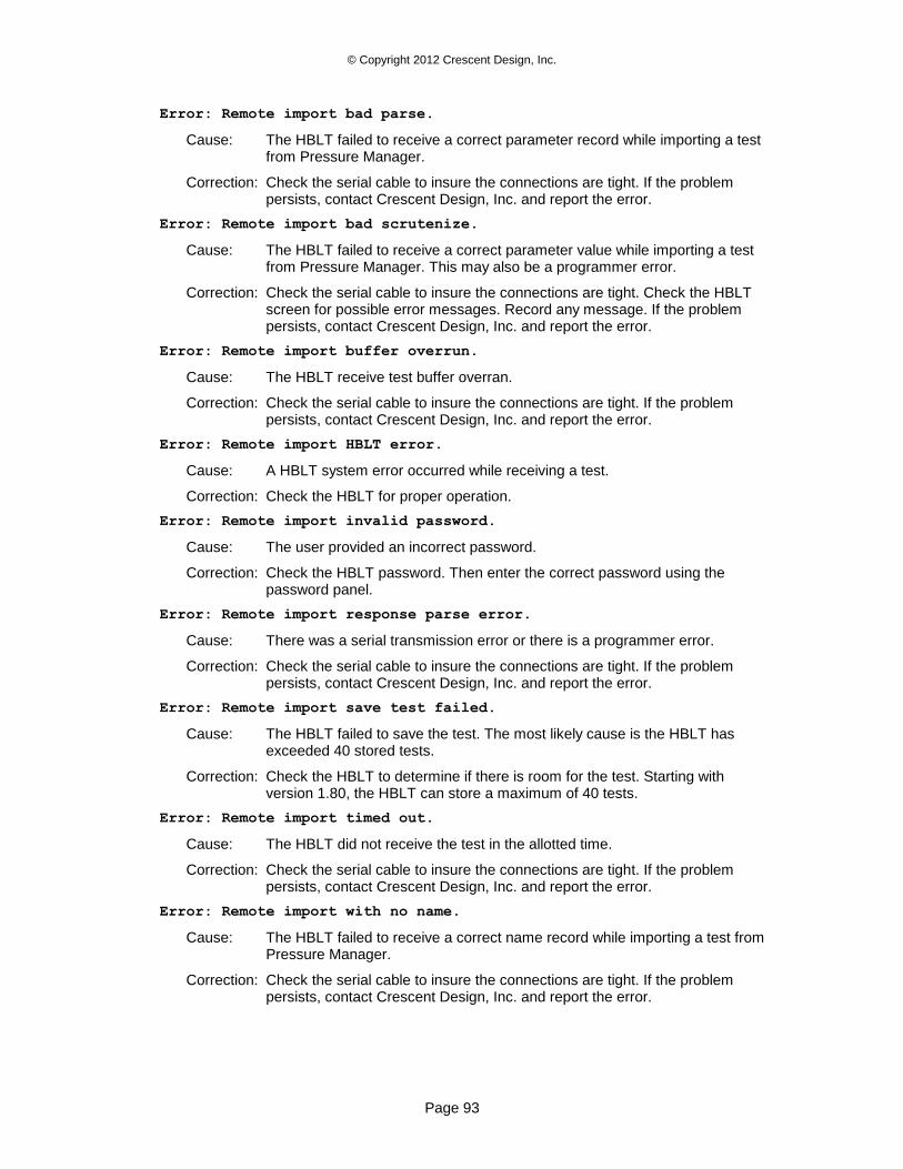
© Copyright 2012 Crescent Design, Inc.
Page 93
Error: Remote import bad parse.
Cause: The HBLT failed to receive a correct parameter record while importing a test from Pressure Manager.
Correction: Check the serial cable to insure the connections are tight. If the problem persists, contact Crescent Design, Inc. and report the error.
Error: Remote import bad scrutenize.
Cause: The HBLT failed to receive a correct parameter value while importing a test from Pressure Manager. This may also be a programmer error.
Correction: Check the serial cable to insure the connections are tight. Check the HBLT screen for possible error messages. Record any message. If the problem persists, contact Crescent Design, Inc. and report the error.
Error: Remote import buffer overrun.
Cause: The HBLT receive test buffer overran.
Correction: Check the serial cable to insure the connections are tight. If the problem persists, contact Crescent Design, Inc. and report the error.
Error: Remote import HBLT error.
Cause: A HBLT system error occurred while receiving a test.
Correction: Check the HBLT for proper operation.
Error: Remote import invalid password.
Cause: The user provided an incorrect password.
Correction: Check the HBLT password. Then enter the correct password using the password panel.
Error: Remote import response parse error.
Cause: There was a serial transmission error or there is a programmer error.
Correction: Check the serial cable to insure the connections are tight. If the problem persists, contact Crescent Design, Inc. and report the error.
Error: Remote import save test failed.
Cause: The HBLT failed to save the test. The most likely cause is the HBLT has exceeded 40 stored tests.
Correction: Check the HBLT to determine if there is room for the test. Starting with version 1.80, the HBLT can store a maximum of 40 tests.
Error: Remote import timed out.
Cause: The HBLT did not receive the test in the allotted time.
Correction: Check the serial cable to insure the connections are tight. If the problem persists, contact Crescent Design, Inc. and report the error.
Error: Remote import with no name.
Cause: The HBLT failed to receive a correct name record while importing a test from Pressure Manager.
Correction: Check the serial cable to insure the connections are tight. If the problem persists, contact Crescent Design, Inc. and report the error.
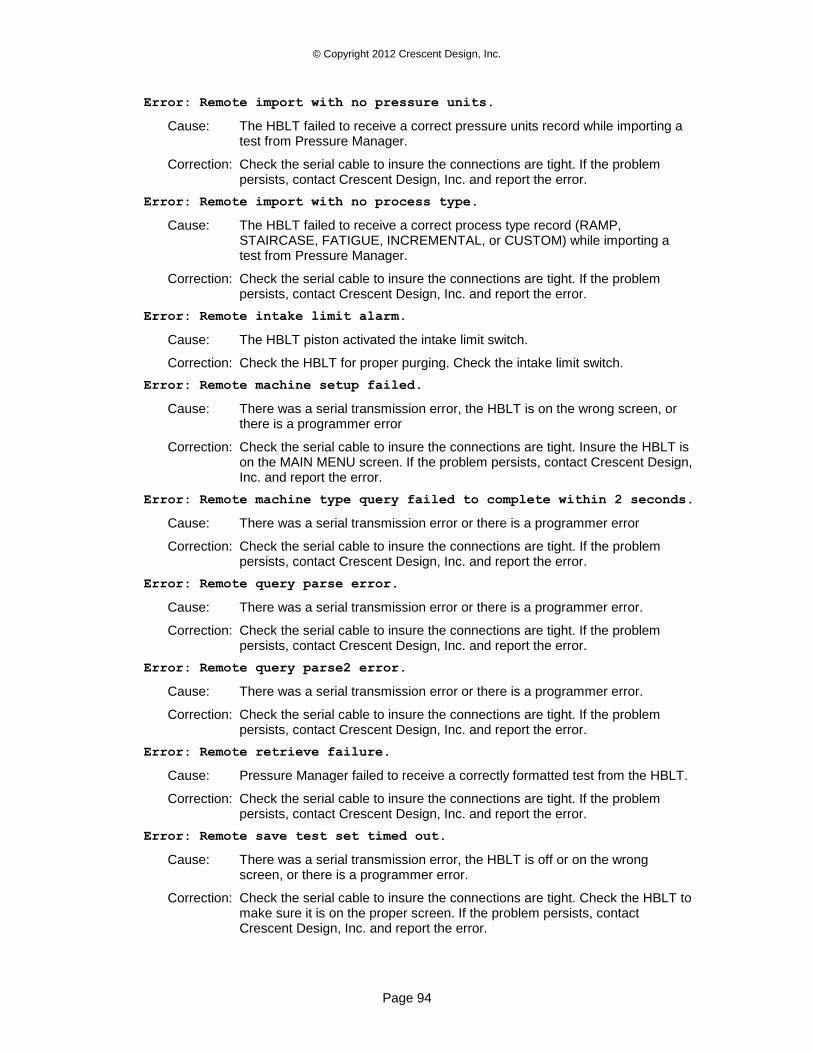
© Copyright 2012 Crescent Design, Inc.
Page 94
Error: Remote import with no pressure units.
Cause: The HBLT failed to receive a correct pressure units record while importing a test from Pressure Manager.
Correction: Check the serial cable to insure the connections are tight. If the problem persists, contact Crescent Design, Inc. and report the error.
Error: Remote import with no process type.
Cause: The HBLT failed to receive a correct process type record (RAMP, STAIRCASE, FATIGUE, INCREMENTAL, or CUSTOM) while importing a test from Pressure Manager.
Correction: Check the serial cable to insure the connections are tight. If the problem persists, contact Crescent Design, Inc. and report the error.
Error: Remote intake limit alarm.
Cause: The HBLT piston activated the intake limit switch.
Correction: Check the HBLT for proper purging. Check the intake limit switch.
Error: Remote machine setup failed.
Cause: There was a serial transmission error, the HBLT is on the wrong screen, or there is a programmer error
Correction: Check the serial cable to insure the connections are tight. Insure the HBLT is on the MAIN MENU screen. If the problem persists, contact Crescent Design, Inc. and report the error.
Error: Remote machine type query failed to complete within 2 seconds.
Cause: There was a serial transmission error or there is a programmer error
Correction: Check the serial cable to insure the connections are tight. If the problem persists, contact Crescent Design, Inc. and report the error.
Error: Remote query parse error.
Cause: There was a serial transmission error or there is a programmer error.
Correction: Check the serial cable to insure the connections are tight. If the problem persists, contact Crescent Design, Inc. and report the error.
Error: Remote query parse2 error.
Cause: There was a serial transmission error or there is a programmer error.
Correction: Check the serial cable to insure the connections are tight. If the problem persists, contact Crescent Design, Inc. and report the error.
Error: Remote retrieve failure.
Cause: Pressure Manager failed to receive a correctly formatted test from the HBLT.
Correction: Check the serial cable to insure the connections are tight. If the problem persists, contact Crescent Design, Inc. and report the error.
Error: Remote save test set timed out.
Cause: There was a serial transmission error, the HBLT is off or on the wrong screen, or there is a programmer error.
Correction: Check the serial cable to insure the connections are tight. Check the HBLT to make sure it is on the proper screen. If the problem persists, contact Crescent Design, Inc. and report the error.
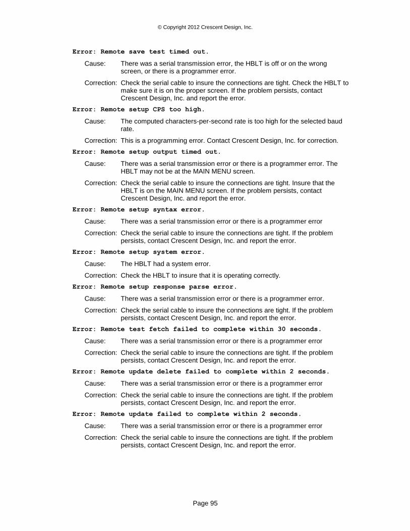
© Copyright 2012 Crescent Design, Inc.
Page 95
Error: Remote save test timed out.
Cause: There was a serial transmission error, the HBLT is off or on the wrong screen, or there is a programmer error.
Correction: Check the serial cable to insure the connections are tight. Check the HBLT to make sure it is on the proper screen. If the problem persists, contact Crescent Design, Inc. and report the error.
Error: Remote setup CPS too high.
Cause: The computed characters-per-second rate is too high for the selected baud rate.
Correction: This is a programming error. Contact Crescent Design, Inc. for correction.
Error: Remote setup output timed out.
Cause: There was a serial transmission error or there is a programmer error. The HBLT may not be at the MAIN MENU screen.
Correction: Check the serial cable to insure the connections are tight. Insure that the HBLT is on the MAIN MENU screen. If the problem persists, contact Crescent Design, Inc. and report the error.
Error: Remote setup syntax error.
Cause: There was a serial transmission error or there is a programmer error
Correction: Check the serial cable to insure the connections are tight. If the problem persists, contact Crescent Design, Inc. and report the error.
Error: Remote setup system error.
Cause: The HBLT had a system error.
Correction: Check the HBLT to insure that it is operating correctly.
Error: Remote setup response parse error.
Cause: There was a serial transmission error or there is a programmer error.
Correction: Check the serial cable to insure the connections are tight. If the problem persists, contact Crescent Design, Inc. and report the error.
Error: Remote test fetch failed to complete within 30 seconds.
Cause: There was a serial transmission error or there is a programmer error
Correction: Check the serial cable to insure the connections are tight. If the problem persists, contact Crescent Design, Inc. and report the error.
Error: Remote update delete failed to complete within 2 seconds.
Cause: There was a serial transmission error or there is a programmer error
Correction: Check the serial cable to insure the connections are tight. If the problem persists, contact Crescent Design, Inc. and report the error.
Error: Remote update failed to complete within 2 seconds.
Cause: There was a serial transmission error or there is a programmer error
Correction: Check the serial cable to insure the connections are tight. If the problem persists, contact Crescent Design, Inc. and report the error.
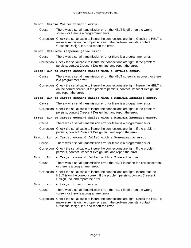
© Copyright 2012 Crescent Design, Inc.
Page 96
Error: Remove Volume timeout error.
Cause: There was a serial transmission error, the HBLT is off or on the wrong screen, or there is a programmer error.
Correction: Check the serial cable to insure the connections are tight. Check the HBLT to make sure it is on the proper screen. If the problem persists, contact Crescent Design, Inc. and report the error.
Error: Retrieve response parse error.
Cause: There was a serial transmission error or there is a programmer error.
Correction: Check the serial cable to insure the connections are tight. If the problem persists, contact Crescent Design, Inc. and report the error.
Error: Run to Target command failed with a Invalid error.
Cause: There was a serial transmission error, the HBLT screen is incorrect, or there is a programmer error.
Correction: Check the serial cable to insure the connections are tight. Insure the HBLT is on the correct screen. If the problem persists, contact Crescent Design, Inc. and report the error.
Error: Run to Target command failed with a Maximum Exceeded error.
Cause: There was a serial transmission error or there is a programmer error.
Correction: Check the serial cable to insure the connections are tight. If the problem persists, contact Crescent Design, Inc. and report the error.
Error: Run to Target command failed with a Minimum Exceeded error.
Cause: There was a serial transmission error or there is a programmer error.
Correction: Check the serial cable to insure the connections are tight. If the problem persists, contact Crescent Design, Inc. and report the error.
Error: Run to Target command failed with a Non-numeric error.
Cause: There was a serial transmission error or there is a programmer error.
Correction: Check the serial cable to insure the connections are tight. If the problem persists, contact Crescent Design, Inc. and report the error.
Error: Run to Target command failed with a Timeout error.
Cause: There was a serial transmission error, the HBLT is not on the correct screen, or there is a programmer error.
Correction: Check the serial cable to insure the connections are tight. Insure that the HBLT is on the correct screen. If the problem persists, contact Crescent Design, Inc. and report the error.
Error: run to target timeout error.
Cause: There was a serial transmission error, the HBLT is off or on the wrong screen, or there is a programmer error
Correction: Check the serial cable to insure the connections are tight. Check the HBLT to make sure it is on the proper screen. If the problem persists, contact Crescent Design, Inc. and report the error.
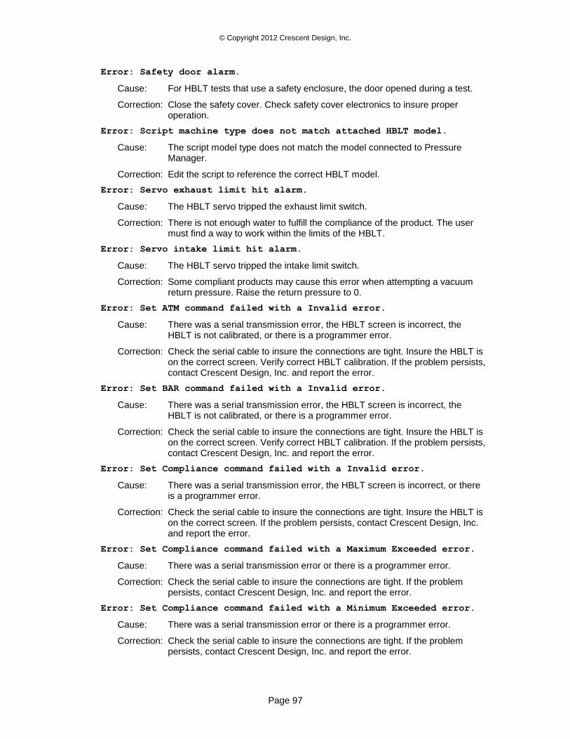
© Copyright 2012 Crescent Design, Inc.
Page 97
Error: Safety door alarm.
Cause: For HBLT tests that use a safety enclosure, the door opened during a test.
Correction: Close the safety cover. Check safety cover electronics to insure proper operation.
Error: Script machine type does not match attached HBLT model.
Cause: The script model type does not match the model connected to Pressure Manager.
Correction: Edit the script to reference the correct HBLT model.
Error: Servo exhaust limit hit alarm.
Cause: The HBLT servo tripped the exhaust limit switch.
Correction: There is not enough water to fulfill the compliance of the product. The user must find a way to work within the limits of the HBLT.
Error: Servo intake limit hit alarm.
Cause: The HBLT servo tripped the intake limit switch.
Correction: Some compliant products may cause this error when attempting a vacuum return pressure. Raise the return pressure to 0.
Error: Set ATM command failed with a Invalid error.
Cause: There was a serial transmission error, the HBLT screen is incorrect, the HBLT is not calibrated, or there is a programmer error.
Correction: Check the serial cable to insure the connections are tight. Insure the HBLT is on the correct screen. Verify correct HBLT calibration. If the problem persists, contact Crescent Design, Inc. and report the error.
Error: Set BAR command failed with a Invalid error.
Cause: There was a serial transmission error, the HBLT screen is incorrect, the HBLT is not calibrated, or there is a programmer error.
Correction: Check the serial cable to insure the connections are tight. Insure the HBLT is on the correct screen. Verify correct HBLT calibration. If the problem persists, contact Crescent Design, Inc. and report the error.
Error: Set Compliance command failed with a Invalid error.
Cause: There was a serial transmission error, the HBLT screen is incorrect, or there is a programmer error.
Correction: Check the serial cable to insure the connections are tight. Insure the HBLT is on the correct screen. If the problem persists, contact Crescent Design, Inc. and report the error.
Error: Set Compliance command failed with a Maximum Exceeded error.
Cause: There was a serial transmission error or there is a programmer error.
Correction: Check the serial cable to insure the connections are tight. If the problem persists, contact Crescent Design, Inc. and report the error.
Error: Set Compliance command failed with a Minimum Exceeded error.
Cause: There was a serial transmission error or there is a programmer error.
Correction: Check the serial cable to insure the connections are tight. If the problem persists, contact Crescent Design, Inc. and report the error.
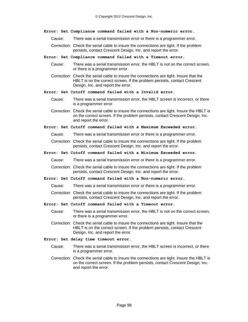
© Copyright 2012 Crescent Design, Inc.
Page 98
Error: Set Compliance command failed with a Non-numeric error.
Cause: There was a serial transmission error or there is a programmer error.
Correction: Check the serial cable to insure the connections are tight. If the problem persists, contact Crescent Design, Inc. and report the error.
Error: Set Compliance command failed with a Timeout error.
Cause: There was a serial transmission error, the HBLT is not on the correct screen, or there is a programmer error.
Correction: Check the serial cable to insure the connections are tight. Insure that the HBLT is on the correct screen. If the problem persists, contact Crescent Design, Inc. and report the error.
Error: Set Cutoff command failed with a Invalid error.
Cause: There was a serial transmission error, the HBLT screen is incorrect, or there is a programmer error.
Correction: Check the serial cable to insure the connections are tight. Insure the HBLT is on the correct screen. If the problem persists, contact Crescent Design, Inc. and report the error.
Error: Set Cutoff command failed with a Maximum Exceeded error.
Cause: There was a serial transmission error or there is a programmer error.
Correction: Check the serial cable to insure the connections are tight. If the problem persists, contact Crescent Design, Inc. and report the error.
Error: Set Cutoff command failed with a Minimum Exceeded error.
Cause: There was a serial transmission error or there is a programmer error.
Correction: Check the serial cable to insure the connections are tight. If the problem persists, contact Crescent Design, Inc. and report the error.
Error: Set Cutoff command failed with a Non-numeric error.
Cause: There was a serial transmission error or there is a programmer error.
Correction: Check the serial cable to insure the connections are tight. If the problem persists, contact Crescent Design, Inc. and report the error.
Error: Set Cutoff command failed with a Timeout error.
Cause: There was a serial transmission error, the HBLT is not on the correct screen, or there is a programmer error.
Correction: Check the serial cable to insure the connections are tight. Insure that the HBLT is on the correct screen. If the problem persists, contact Crescent Design, Inc. and report the error.
Error: Set delay time timeout error.
Cause: There was a serial transmission error, the HBLT screen is incorrect, or there is a programmer error.
Correction: Check the serial cable to insure the connections are tight. Insure the HBLT is on the correct screen. If the problem persists, contact Crescent Design, Inc. and report the error.
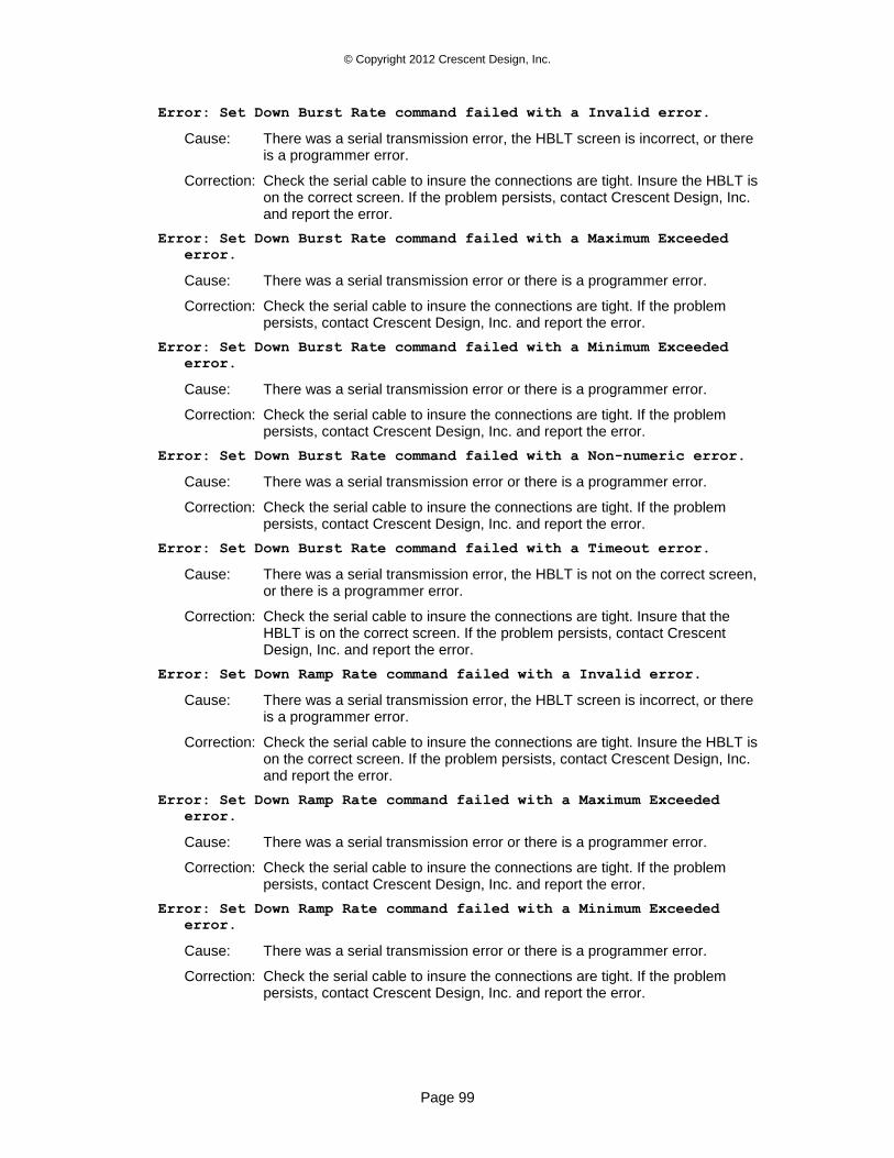
© Copyright 2012 Crescent Design, Inc.
Page 99
Error: Set Down Burst Rate command failed with a Invalid error.
Cause: There was a serial transmission error, the HBLT screen is incorrect, or there is a programmer error.
Correction: Check the serial cable to insure the connections are tight. Insure the HBLT is on the correct screen. If the problem persists, contact Crescent Design, Inc. and report the error.
Error: Set Down Burst Rate command failed with a Maximum Exceeded
error.
Cause: There was a serial transmission error or there is a programmer error.
Correction: Check the serial cable to insure the connections are tight. If the problem persists, contact Crescent Design, Inc. and report the error.
Error: Set Down Burst Rate command failed with a Minimum Exceeded
error.
Cause: There was a serial transmission error or there is a programmer error.
Correction: Check the serial cable to insure the connections are tight. If the problem persists, contact Crescent Design, Inc. and report the error.
Error: Set Down Burst Rate command failed with a Non-numeric error.
Cause: There was a serial transmission error or there is a programmer error.
Correction: Check the serial cable to insure the connections are tight. If the problem persists, contact Crescent Design, Inc. and report the error.
Error: Set Down Burst Rate command failed with a Timeout error.
Cause: There was a serial transmission error, the HBLT is not on the correct screen, or there is a programmer error.
Correction: Check the serial cable to insure the connections are tight. Insure that the HBLT is on the correct screen. If the problem persists, contact Crescent Design, Inc. and report the error.
Error: Set Down Ramp Rate command failed with a Invalid error.
Cause: There was a serial transmission error, the HBLT screen is incorrect, or there is a programmer error.
Correction: Check the serial cable to insure the connections are tight. Insure the HBLT is on the correct screen. If the problem persists, contact Crescent Design, Inc. and report the error.
Error: Set Down Ramp Rate command failed with a Maximum Exceeded
error.
Cause: There was a serial transmission error or there is a programmer error.
Correction: Check the serial cable to insure the connections are tight. If the problem persists, contact Crescent Design, Inc. and report the error.
Error: Set Down Ramp Rate command failed with a Minimum Exceeded
error.
Cause: There was a serial transmission error or there is a programmer error.
Correction: Check the serial cable to insure the connections are tight. If the problem persists, contact Crescent Design, Inc. and report the error.
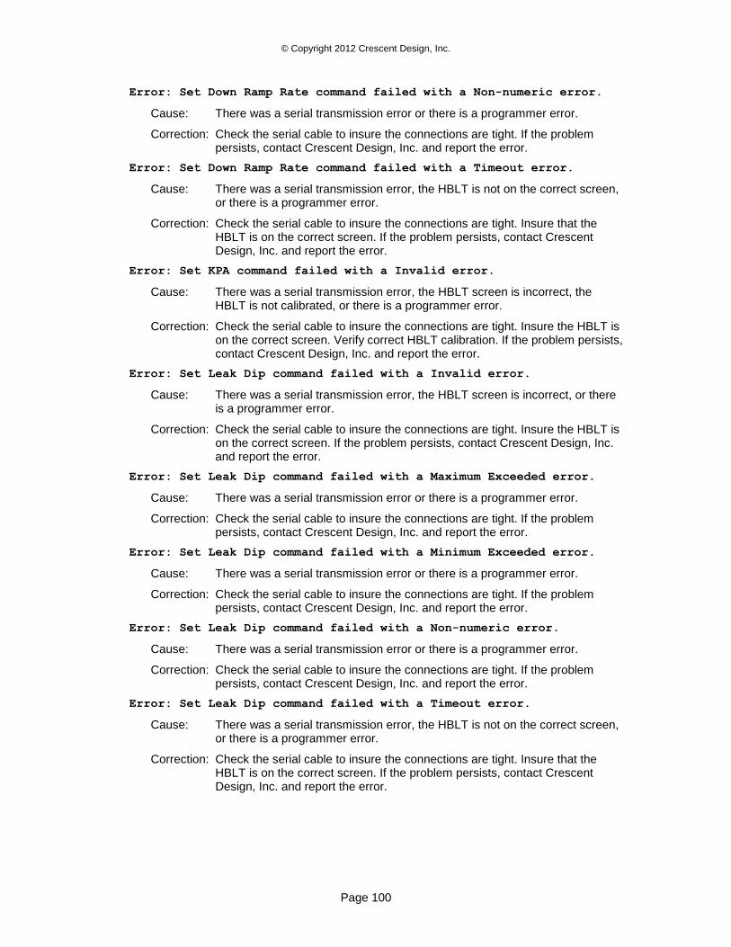
© Copyright 2012 Crescent Design, Inc.
Page 100
Error: Set Down Ramp Rate command failed with a Non-numeric error.
Cause: There was a serial transmission error or there is a programmer error.
Correction: Check the serial cable to insure the connections are tight. If the problem persists, contact Crescent Design, Inc. and report the error.
Error: Set Down Ramp Rate command failed with a Timeout error.
Cause: There was a serial transmission error, the HBLT is not on the correct screen, or there is a programmer error.
Correction: Check the serial cable to insure the connections are tight. Insure that the HBLT is on the correct screen. If the problem persists, contact Crescent Design, Inc. and report the error.
Error: Set KPA command failed with a Invalid error.
Cause: There was a serial transmission error, the HBLT screen is incorrect, the HBLT is not calibrated, or there is a programmer error.
Correction: Check the serial cable to insure the connections are tight. Insure the HBLT is on the correct screen. Verify correct HBLT calibration. If the problem persists, contact Crescent Design, Inc. and report the error.
Error: Set Leak Dip command failed with a Invalid error.
Cause: There was a serial transmission error, the HBLT screen is incorrect, or there is a programmer error.
Correction: Check the serial cable to insure the connections are tight. Insure the HBLT is on the correct screen. If the problem persists, contact Crescent Design, Inc. and report the error.
Error: Set Leak Dip command failed with a Maximum Exceeded error.
Cause: There was a serial transmission error or there is a programmer error.
Correction: Check the serial cable to insure the connections are tight. If the problem persists, contact Crescent Design, Inc. and report the error.
Error: Set Leak Dip command failed with a Minimum Exceeded error.
Cause: There was a serial transmission error or there is a programmer error.
Correction: Check the serial cable to insure the connections are tight. If the problem persists, contact Crescent Design, Inc. and report the error.
Error: Set Leak Dip command failed with a Non-numeric error.
Cause: There was a serial transmission error or there is a programmer error.
Correction: Check the serial cable to insure the connections are tight. If the problem persists, contact Crescent Design, Inc. and report the error.
Error: Set Leak Dip command failed with a Timeout error.
Cause: There was a serial transmission error, the HBLT is not on the correct screen, or there is a programmer error.
Correction: Check the serial cable to insure the connections are tight. Insure that the HBLT is on the correct screen. If the problem persists, contact Crescent Design, Inc. and report the error.
© Copyright 2012 Crescent Design, Inc.
Page 101
Error: Set Leak Rate command failed with a Invalid error.
Cause: There was a serial transmission error, the HBLT screen is incorrect, or there is a programmer error.
Correction: Check the serial cable to insure the connections are tight. Insure the HBLT is on the correct screen. If the problem persists, contact Crescent Design, Inc. and report the error.
Error: Set Leak Rate command failed with a Maximum Exceeded error.
Cause: There was a serial transmission error or there is a programmer error.
Correction: Check the serial cable to insure the connections are tight. If the problem persists, contact Crescent Design, Inc. and report the error.
Error: Set Leak Rate command failed with a Minimum Exceeded error.
Cause: There was a serial transmission error or there is a programmer error.
Correction: Check the serial cable to insure the connections are tight. If the problem persists, contact Crescent Design, Inc. and report the error.
Error: Set Leak Rate command failed with a Non-numeric error.
Cause: There was a serial transmission error or there is a programmer error.
Correction: Check the serial cable to insure the connections are tight. If the problem persists, contact Crescent Design, Inc. and report the error.
Error: Set Leak Rate command failed with a Timeout error.
Cause: There was a serial transmission error, the HBLT is not on the correct screen, or there is a programmer error.
Correction: Check the serial cable to insure the connections are tight. Insure that the HBLT is on the correct screen. If the problem persists, contact Crescent Design, Inc. and report the error.
Error: Set maintain time timeout error.
Cause: There was a serial transmission error, the HBLT screen is incorrect, or there is a programmer error.
Correction: Check the serial cable to insure the connections are tight. Insure the HBLT is on the correct screen. If the problem persists, contact Crescent Design, Inc. and report the error.
Error: Set Message command failed with a Invalid error.
Cause: There was a serial transmission error, the HBLT screen is incorrect, or there is a programmer error.
Correction: Check the serial cable to insure the connections are tight. Insure the HBLT is on the correct screen. If the problem persists, contact Crescent Design, Inc. and report the error.
Error: Set Message command failed with a Timeout error.
Cause: There was a serial transmission error, the HBLT is not on the correct screen, or there is a programmer error.
Correction: Check the serial cable to insure the connections are tight. Insure that the HBLT is on the correct screen. If the problem persists, contact Crescent Design, Inc. and report the error.
© Copyright 2012 Crescent Design, Inc.
Page 102
Error: Set Prepare For Vacuum command failed with a Invalid error.
Cause: There was a serial transmission error, the HBLT screen is incorrect, or there is a programmer error.
Correction: Check the serial cable to insure the connections are tight. Insure the HBLT is on the correct screen. If the problem persists, contact Crescent Design, Inc. and report the error.
Error: Set Prepare For No Vacuum command failed with a Invalid error.
Cause: There was a serial transmission error, the HBLT screen is incorrect, or there is a programmer error.
Correction: Check the serial cable to insure the connections are tight. Insure the HBLT is on the correct screen. If the problem persists, contact Crescent Design, Inc. and report the error.
Error: Set PSI command failed with a Invalid error.
Cause: There was a serial transmission error, the HBLT screen is incorrect, the HBLT is not calibrated, or there is a programmer error.
Correction: Check the serial cable to insure the connections are tight. Insure the HBLT is on the correct screen. Verify correct HBLT calibration. If the problem persists, contact Crescent Design, Inc. and report the error.
Error: Set Redirect Off command failed with a Invalid error.
Cause: There was a serial transmission error, the HBLT screen is incorrect, or there is a programmer error.
Correction: Check the serial cable to insure the connections are tight. Insure the HBLT is on the correct screen. If the problem persists, contact Crescent Design, Inc. and report the error.
Error: Set Redirect On command failed with a Invalid error.
Cause: There was a serial transmission error, the HBLT screen is incorrect, or there is a programmer error.
Correction: Check the serial cable to insure the connections are tight. Insure the HBLT is on the correct screen. If the problem persists, contact Crescent Design, Inc. and report the error.
Error: Set Stream Enable command failed with a Invalid error.
Cause: There was a serial transmission error, the HBLT screen is incorrect, or there is a programmer error.
Correction: Check the serial cable to insure the connections are tight. Insure the HBLT is on the correct screen. If the problem persists, contact Crescent Design, Inc. and report the error.
Error: Set Stream Disable command failed with a Invalid error.
Cause: There was a serial transmission error, the HBLT screen is incorrect, or there is a programmer error.
Correction: Check the serial cable to insure the connections are tight. Insure the HBLT is on the correct screen. If the problem persists, contact Crescent Design, Inc. and report the error.
© Copyright 2012 Crescent Design, Inc.
Page 103
Error: Set Up Burst Rate command failed with a Invalid error.
Cause: There was a serial transmission error, the HBLT screen is incorrect, or there is a programmer error.
Correction: Check the serial cable to insure the connections are tight. Insure the HBLT is on the correct screen. If the problem persists, contact Crescent Design, Inc. and report the error.
Error: Set Up Burst Rate command failed with a Maximum Exceeded
error.
Cause: There was a serial transmission error or there is a programmer error.
Correction: Check the serial cable to insure the connections are tight. If the problem persists, contact Crescent Design, Inc. and report the error.
Error: Set Up Burst Rate command failed with a Minimum Exceeded
error.
Cause: There was a serial transmission error or there is a programmer error.
Correction: Check the serial cable to insure the connections are tight. If the problem persists, contact Crescent Design, Inc. and report the error.
Error: Set Up Burst Rate command failed with a Non-numeric error.
Cause: There was a serial transmission error or there is a programmer error.
Correction: Check the serial cable to insure the connections are tight. If the problem persists, contact Crescent Design, Inc. and report the error.
Error: Set Up Burst Rate command failed with a Timeout error.
Cause: There was a serial transmission error, the HBLT is not on the correct screen, or there is a programmer error.
Correction: Check the serial cable to insure the connections are tight. Insure that the HBLT is on the correct screen. If the problem persists, contact Crescent Design, Inc. and report the error.
Error: Set Up Ramp Rate command failed with a Invalid error.
Cause: There was a serial transmission error, the HBLT screen is incorrect, or there is a programmer error.
Correction: Check the serial cable to insure the connections are tight. Insure the HBLT is on the correct screen. If the problem persists, contact Crescent Design, Inc. and report the error.
Error: Set Up Ramp Rate command failed with a Maximum Exceeded error.
Cause: There was a serial transmission error or there is a programmer error.
Correction: Check the serial cable to insure the connections are tight. If the problem persists, contact Crescent Design, Inc. and report the error.
Error: Set Up Ramp Rate command failed with a Minimum Exceeded error.
Cause: There was a serial transmission error or there is a programmer error.
Correction: Check the serial cable to insure the connections are tight. If the problem persists, contact Crescent Design, Inc. and report the error.
© Copyright 2012 Crescent Design, Inc.
Page 104
Error: Set Up Ramp Rate command failed with a Non-numeric error.
Cause: There was a serial transmission error or there is a programmer error.
Correction: Check the serial cable to insure the connections are tight. If the problem persists, contact Crescent Design, Inc. and report the error.
Error: Set Up Ramp Rate command failed with a Timeout error.
Cause: There was a serial transmission error, the HBLT is not on the correct screen, or there is a programmer error.
Correction: Check the serial cable to insure the connections are tight. Insure that the HBLT is on the correct screen. If the problem persists, contact Crescent Design, Inc. and report the error.
Error: Set Volume Press Limit timeout error.
Cause: There was a serial transmission error, the HBLT is off or on the wrong screen, or there is a programmer error.
Correction: Check the serial cable to insure the connections are tight. Check the HBLT to make sure it is on the proper screen. If the problem persists, contact Crescent Design, Inc. and report the error.
Error: Set Volume Rate timeout error.
Cause: There was a serial transmission error, the HBLT is off or on the wrong screen, or there is a programmer error.
Correction: Check the serial cable to insure the connections are tight. Check the HBLT to make sure it is on the proper screen. If the problem persists, contact Crescent Design, Inc. and report the error.
Error: Setup HBLT CPS to high error.
Cause: There was a serial transmission error or there is a programmer error.
Correction: Check the serial cable to insure the connections are tight. If the problem persists, contact Crescent Design, Inc. and report the error.
Error: Setup HBLT parse error.
Cause: There was a serial transmission error or there is a programmer error.
Correction: Check the serial cable to insure the connections are tight. If the problem persists, contact Crescent Design, Inc. and report the error.
Error: Setup HBLT syntax error.
Cause: There was a serial transmission error or there is a programmer error.
Correction: Check the serial cable to insure the connections are tight. If the problem persists, contact Crescent Design, Inc. and report the error.
Error: Setup HBLT system error.
Cause: There was a serial transmission error or there is a programmer error.
Correction: Check the serial cable to insure the connections are tight. If the problem persists, contact Crescent Design, Inc. and report the error.
Error: Setup HBLT timeout error.
Cause: There was a serial transmission error or there is a programmer error.
Correction: Check the serial cable to insure the connections are tight. If the problem persists, contact Crescent Design, Inc. and report the error.
© Copyright 2012 Crescent Design, Inc.
Page 105
Error: Setup output timeout error.
Cause: There was a serial transmission error, the HBLT is off or on the wrong screen, or there is a programmer error
Correction: Check the serial cable to insure the connections are tight. Check the HBLT to make sure it is on the proper screen. If the problem persists, contact Crescent Design, Inc. and report the error.
Error: Sequence error in data file.
Cause: The most likely cause is that someone edited the data file. Or, the file is not a Pressure Manager data file.
Correction: Make sure the file read is a Pressure Manager file. Correct any editing errors.
Error: Stop Motor command failed with a Invalid error.
Cause: There was a serial transmission error, the HBLT screen is incorrect, or there is a programmer error.
Correction: Check the serial cable to insure the connections are tight. Insure the HBLT is on the correct screen. If the problem persists, contact Crescent Design, Inc. and report the error.
Error: stop motor timeout error.
Cause: There was a serial transmission error, the HBLT is off or on the wrong screen, or there is a programmer error
Correction: Check the serial cable to insure the connections are tight. Check the HBLT to make sure it is on the proper screen. If the problem persists, contact Crescent Design, Inc. and report the error.
Error: Stream data error.
Cause: There was a serial transmission error or there is a programmer error.
Correction: Check the serial cable to insure the connections are tight. If the problem persists, contact Crescent Design, Inc. and report the error.
Error: stream disable timeout error.
Cause: There was a serial transmission error, the HBLT is off or on the wrong screen, or there is a programmer error
Correction: Check the serial cable to insure the connections are tight. Check the HBLT to make sure it is on the proper screen. If the problem persists, contact Crescent Design, Inc. and report the error.
Error: stream enable timeout error.
Cause: There was a serial transmission error, the HBLT is off or on the wrong screen, or there is a programmer error
Correction: Check the serial cable to insure the connections are tight. Check the HBLT to make sure it is on the proper screen. If the problem persists, contact Crescent Design, Inc. and report the error.
Error: Smart Manifold channel deselect command – parameter non-
numeric character.
Cause: There was a serial transmission error, the HBLT is off or on the wrong screen, or there is a programmer error.
Correction: Check the serial cable to insure the connections are tight. Check the HBLT to make sure it is on the proper screen. If the problem persists, contact Crescent Design, Inc. and report the error.
© Copyright 2012 Crescent Design, Inc.
Page 106
Error: Smart Manifold channel deselect command – parameter out of
range.
Cause: There was a serial transmission error, the HBLT is off or on the wrong screen, or there is a programmer error.
Correction: Check the serial cable to insure the connections are tight. Check the HBLT to make sure it is on the proper screen. If the problem persists, contact Crescent Design, Inc. and report the error.
Error: Smart Manifold channel Deselect command – Smart Manifold not
attached to HBLT.
Cause: There was a serial transmission error, the HBLT is off or on the wrong screen, or there is a programmer error.
Correction: Check the serial cable to insure the connections are tight. Check the HBLT to make sure it is on the proper screen. If the problem persists, contact Crescent Design, Inc. and report the error.
Error: Smart Manifold channel deselect parse error.
Cause: There was a serial transmission error, the HBLT is off or on the wrong screen, or there is a programmer error.
Correction: Check the serial cable to insure the connections are tight. Check the HBLT to make sure it is on the proper screen. If the problem persists, contact Crescent Design, Inc. and report the error.
Error: Smart Manifold channel deselect timed out.
Cause: There was a serial transmission error, the HBLT is off or on the wrong screen, or there is a programmer error.
Correction: Check the serial cable to insure the connections are tight. Check the HBLT to make sure it is on the proper screen. If the problem persists, contact Crescent Design, Inc. and report the error.
Error: Smart Manifold channel deselect timeout error.
Cause: There was a serial transmission error, the HBLT is off or on the wrong screen, or there is a programmer error.
Correction: Check the serial cable to insure the connections are tight. Check the HBLT to make sure it is on the proper screen. If the problem persists, contact Crescent Design, Inc. and report the error.
Error: Smart Manifold channel select command – parameter non-numeric
character.
Cause: There was a serial transmission error, the HBLT is off or on the wrong screen, or there is a programmer error.
Correction: Check the serial cable to insure the connections are tight. Check the HBLT to make sure it is on the proper screen. If the problem persists, contact Crescent Design, Inc. and report the error.
Error: Smart Manifold channel select command – parameter out of
range.
Cause: There was a serial transmission error, the HBLT is off or on the wrong screen, or there is a programmer error.
Correction: Check the serial cable to insure the connections are tight. Check the HBLT to make sure it is on the proper screen. If the problem persists, contact Crescent Design, Inc. and report the error.
© Copyright 2012 Crescent Design, Inc.
Page 107
Error: Smart Manifold channel select command – Smart Manifold not
attached to HBLT.
Cause: There was a serial transmission error, the HBLT is off or on the wrong screen, or there is a programmer error.
Correction: Check the serial cable to insure the connections are tight. Check the HBLT to make sure it is on the proper screen. If the problem persists, contact Crescent Design, Inc. and report the error.
Error: Smart Manifold channel select parse error.
Cause: There was a serial transmission error, the HBLT is off or on the wrong screen, or there is a programmer error.
Correction: Check the serial cable to insure the connections are tight. Check the HBLT to make sure it is on the proper screen. If the problem persists, contact Crescent Design, Inc. and report the error.
Error: Smart Manifold channel select timed out.
Cause: There was a serial transmission error, the HBLT is off or on the wrong screen, or there is a programmer error.
Correction: Check the serial cable to insure the connections are tight. Check the HBLT to make sure it is on the proper screen. If the problem persists, contact Crescent Design, Inc. and report the error.
Error: Smart Manifold channel Select timeout error.
Cause: There was a serial transmission error, the HBLT is off or on the wrong screen, or there is a programmer error.
Correction: Check the serial cable to insure the connections are tight. Check the HBLT to make sure it is on the proper screen. If the problem persists, contact Crescent Design, Inc. and report the error.
Error: Smart Manifold get input command – input is on.
Cause: There was a serial transmission error, the HBLT is off or on the wrong screen, or there is a programmer error.
Correction: Check the serial cable to insure the connections are tight. Check the HBLT to make sure it is on the proper screen. If the problem persists, contact Crescent Design, Inc. and report the error.
Error: Smart Manifold get input command – parameter out of range.
Cause: There was a serial transmission error, the HBLT is off or on the wrong screen, or there is a programmer error.
Correction: Check the serial cable to insure the connections are tight. Check the HBLT to make sure it is on the proper screen. If the problem persists, contact Crescent Design, Inc. and report the error.
Error: Smart Manifold get input command – Smart Manifold not attached
to HBLT.
Cause: There was a serial transmission error, the HBLT is off or on the wrong screen, or there is a programmer error.
Correction: Check the serial cable to insure the connections are tight. Check the HBLT to make sure it is on the proper screen. If the problem persists, contact Crescent Design, Inc. and report the error.
© Copyright 2012 Crescent Design, Inc.
Page 108
Error: Smart Manifold get input parse error.
Cause: There was a serial transmission error, the HBLT is off or on the wrong screen, or there is a programmer error.
Correction: Check the serial cable to insure the connections are tight. Check the HBLT to make sure it is on the proper screen. If the problem persists, contact Crescent Design, Inc. and report the error.
Error: Smart Manifold get input timed out.
Cause: There was a serial transmission error, the HBLT is off or on the wrong screen, or there is a programmer error.
Correction: Check the serial cable to insure the connections are tight. Check the HBLT to make sure it is on the proper screen. If the problem persists, contact Crescent Design, Inc. and report the error.
Error: Smart Manifold get status command – Smart Manifold not
attached to HBLT.
Cause: There was a serial transmission error, the HBLT is off or on the wrong screen, or there is a programmer error.
Correction: Check the serial cable to insure the connections are tight. Check the HBLT to make sure it is on the proper screen. If the problem persists, contact Crescent Design, Inc. and report the error.
Error: Smart Manifold Get Status timeout error.
Cause: There was a serial transmission error, the HBLT is off or on the wrong screen, or there is a programmer error.
Correction: Check the serial cable to insure the connections are tight. Check the HBLT to make sure it is on the proper screen. If the problem persists, contact Crescent Design, Inc. and report the error.
Error: Smart Manifold get test results command – reports no test
results.
Cause: The HBLT reports that there are no test results.
Correction: The test results are available after a test or script completes and before resetting the HBLT.
Error: Smart Manifold get test results command – Smart Manifold not
attached to HBLT.
Cause: There was a serial transmission error, the HBLT is off or on the wrong screen, or there is a programmer error.
Correction: Check the serial cable to insure the connections are tight. Check the HBLT to make sure it is on the proper screen. If the problem persists, contact Crescent Design, Inc. and report the error.
Error: Smart Manifold Get test results timeout error.
Cause: There was a serial transmission error, the HBLT is off or on the wrong screen, or there is a programmer error.
Correction: Check the serial cable to insure the connections are tight. Check the HBLT to make sure it is on the proper screen. If the problem persists, contact Crescent Design, Inc. and report the error.
© Copyright 2012 Crescent Design, Inc.
Page 109
Error: Smart Manifold output off command – parameter out of range.
Cause: There was a serial transmission error, the HBLT is off or on the wrong screen, or there is a programmer error.
Correction: Check the serial cable to insure the connections are tight. Check the HBLT to make sure it is on the proper screen. If the problem persists, contact Crescent Design, Inc. and report the error.
Error: Smart Manifold output off command – Smart Manifold not
attached to HBLT.
Cause: There was a serial transmission error, the HBLT is off or on the wrong screen, or there is a programmer error.
Correction: Check the serial cable to insure the connections are tight. Check the HBLT to make sure it is on the proper screen. If the problem persists, contact Crescent Design, Inc. and report the error.
Error: Smart Manifold output off parse error.
Cause: There was a serial transmission error, the HBLT is off or on the wrong screen, or there is a programmer error.
Correction: Check the serial cable to insure the connections are tight. Check the HBLT to make sure it is on the proper screen. If the problem persists, contact Crescent Design, Inc. and report the error.
Error: Smart Manifold output off timed out.
Cause: There was a serial transmission error, the HBLT is off or on the wrong screen, or there is a programmer error.
Correction: Check the serial cable to insure the connections are tight. Check the HBLT to make sure it is on the proper screen. If the problem persists, contact Crescent Design, Inc. and report the error.
Error: Smart Manifold Output off timeout error.
Cause: There was a serial transmission error, the HBLT is off or on the wrong screen, or there is a programmer error.
Correction: Check the serial cable to insure the connections are tight. Check the HBLT to make sure it is on the proper screen. If the problem persists, contact Crescent Design, Inc. and report the error.
Error: Smart Manifold output on command – parameter out of range.
Cause: There was a serial transmission error, the HBLT is off or on the wrong screen, or there is a programmer error.
Correction: Check the serial cable to insure the connections are tight. Check the HBLT to make sure it is on the proper screen. If the problem persists, contact Crescent Design, Inc. and report the error.
Error: Smart Manifold output on command – Smart Manifold not attached
to HBLT.
Cause: There was a serial transmission error, the HBLT is off or on the wrong screen, or there is a programmer error.
Correction: Check the serial cable to insure the connections are tight. Check the HBLT to make sure it is on the proper screen. If the problem persists, contact Crescent Design, Inc. and report the error.
© Copyright 2012 Crescent Design, Inc.
Page 110
Error: Smart Manifold output on parse error.
Cause: There was a serial transmission error, the HBLT is off or on the wrong screen, or there is a programmer error.
Correction: Check the serial cable to insure the connections are tight. Check the HBLT to make sure it is on the proper screen. If the problem persists, contact Crescent Design, Inc. and report the error.
Error: Smart Manifold output on timed out.
Cause: There was a serial transmission error, the HBLT is off or on the wrong screen, or there is a programmer error.
Correction: Check the serial cable to insure the connections are tight. Check the HBLT to make sure it is on the proper screen. If the problem persists, contact Crescent Design, Inc. and report the error.
Error: Smart Manifold Output on timeout error.
Cause: There was a serial transmission error, the HBLT is off or on the wrong screen, or there is a programmer error.
Correction: Check the serial cable to insure the connections are tight. Check the HBLT to make sure it is on the proper screen. If the problem persists, contact Crescent Design, Inc. and report the error.
Error: Smart Manifold Parallel Mode timeout error.
Cause: There was a serial transmission error, the HBLT is off or on the wrong screen, or there is a programmer error.
Correction: Check the serial cable to insure the connections are tight. Check the HBLT to make sure it is on the proper screen. If the problem persists, contact Crescent Design, Inc. and report the error.
Error: Smart Manifold Sequential Mode timeout error.
Cause: There was a serial transmission error, the HBLT is off or on the wrong screen, or there is a programmer error.
Correction: Check the serial cable to insure the connections are tight. Check the HBLT to make sure it is on the proper screen. If the problem persists, contact Crescent Design, Inc. and report the error.
Error: Smart Manifold set find burst port cutoff psi timeout error.
Cause: There was a serial transmission error, the HBLT is off or on the wrong screen, or there is a programmer error.
Correction: Check the serial cable to insure the connections are tight. Check the HBLT to make sure it is on the proper screen. If the problem persists, contact Crescent Design, Inc. and report the error.
Error: Smart Manifold set find burst port purge rate timeout error.
Cause: There was a serial transmission error, the HBLT is off or on the wrong screen, or there is a programmer error.
Correction: Check the serial cable to insure the connections are tight. Check the HBLT to make sure it is on the proper screen. If the problem persists, contact Crescent Design, Inc. and report the error.
© Copyright 2012 Crescent Design, Inc.
Page 111
Error: Smart Manifold set find burst port timeout timeout error.
Cause: There was a serial transmission error, the HBLT is off or on the wrong screen, or there is a programmer error.
Correction: Check the serial cable to insure the connections are tight. Check the HBLT to make sure it is on the proper screen. If the problem persists, contact Crescent Design, Inc. and report the error.
Error: Smart Manifold set leak delay timeout error.
Cause: There was a serial transmission error, the HBLT is off or on the wrong screen, or there is a programmer error.
Correction: Check the serial cable to insure the connections are tight. Check the HBLT to make sure it is on the proper screen. If the problem persists, contact Crescent Design, Inc. and report the error.
Error: Smart Manifold set leak maintain timeout error.
Cause: There was a serial transmission error, the HBLT is off or on the wrong screen, or there is a programmer error.
Correction: Check the serial cable to insure the connections are tight. Check the HBLT to make sure it is on the proper screen. If the problem persists, contact Crescent Design, Inc. and report the error.
Error: Smart Manifold set manifold leak target timeout error.
Cause: There was a serial transmission error, the HBLT is off or on the wrong screen, or there is a programmer error.
Correction: Check the serial cable to insure the connections are tight. Check the HBLT to make sure it is on the proper screen. If the problem persists, contact Crescent Design, Inc. and report the error.
Error: Smart Manifold set multport compliance timeout error.
Cause: There was a serial transmission error, the HBLT is off or on the wrong screen, or there is a programmer error.
Correction: Check the serial cable to insure the connections are tight. Check the HBLT to make sure it is on the proper screen. If the problem persists, contact Crescent Design, Inc. and report the error.
Error: Smart Manifold set multport compliance count timeout error.
Cause: There was a serial transmission error, the HBLT is off or on the wrong screen, or there is a programmer error.
Correction: Check the serial cable to insure the connections are tight. Check the HBLT to make sure it is on the proper screen. If the problem persists, contact Crescent Design, Inc. and report the error.
Error: Smart Manifold Single Mode timeout error.
Cause: There was a serial transmission error, the HBLT is off or on the wrong screen, or there is a programmer error.
Correction: Check the serial cable to insure the connections are tight. Check the HBLT to make sure it is on the proper screen. If the problem persists, contact Crescent Design, Inc. and report the error.
© Copyright 2012 Crescent Design, Inc.
Page 112
Error: Smart Manifold: invalid number of ports selected.
Cause: There are no ports selected, or if the Smart Manifold mode is single, there are more than one ports selected.
Correction: Select the correct number of ports.
Error: Syntax error found in data file.
Cause: The most likely cause is that someone edited the data file. Or, the file is not a Pressure Manager data file.
Correction: Make sure the file read is a Pressure Manager file. Correct any editing errors.
Error: Turn stream data off error.
Cause: There was a serial transmission error or there is a programmer error.
Correction: Check the serial cable to insure the connections are tight. If the problem persists, contact Crescent Design, Inc. and report the error.
Error: Turn stream data on error.
Cause: There was a serial transmission error or there is a programmer error.
Correction: Check the serial cable to insure the connections are tight. If the problem persists, contact Crescent Design, Inc. and report the error.
Error: up burst rate timeout error.
Cause: There was a serial transmission error, the HBLT is off or on the wrong screen, or there is a programmer error
Correction: Check the serial cable to insure the connections are tight. Check the HBLT to make sure it is on the proper screen. If the problem persists, contact Crescent Design, Inc. and report the error.
Error: up ramp rate timeout error.
Cause: There was a serial transmission error, the HBLT is off or on the wrong screen, or there is a programmer error
Correction: Check the serial cable to insure the connections are tight. Check the HBLT to make sure it is on the proper screen. If the problem persists, contact Crescent Design, Inc. and report the error.
Error: Vacuum position timeout error.
Cause: There was a serial transmission error, the HBLT is off or on the wrong screen, or there is a programmer error.
Correction: Check the serial cable to insure the connections are tight. Check the HBLT to make sure it is on the proper screen. If the problem persists, contact Crescent Design, Inc. and report the error.
Password: Remote delete invalid password.
Cause: The HBLT received an invalid password for the delete operation.
Correction: Check the HBLT password. Use the password window to enter the correct password for the delete.
Password: Remote delete invalid password character.
Cause: The HBLT detected an invalid character in the password record. There was a serial transmission error or there is a programmer error.
Correction: Check the serial cable to insure the connections are tight. If the problem persists, contact Crescent Design, Inc. and report the error.
© Copyright 2012 Crescent Design, Inc.
Page 113
Password: Remote delete password buffer overrun.
Cause: The HBLT received too many characters in the password record.
Correction: Check the serial cable to insure the connections are tight. If the problem persists, contact Crescent Design, Inc. and report the error.
Warning: Failed to find or create DEFAULT.CAL.
Cause: Failed to open a new default calibration file.
Correction: Check for a full disk or a write protected disk.
Warning: Failed to open micrometer serial port.
Cause: Failed to open the serial port for the micrometer.
Correction: Check the micrometer serial port assignment to insure that the selected port exists and is functional.
Low Level Error Messages
This class of error messages are mainly software traps to catch programming errors. These error messages occur in two places. The first is the log panel. The second is the ERRORS.LOG file found in the Pressure Manager directory.
These error messages assist the programmer in detecting and locating software flaws. If one of these messages appears in the log panel, please record the exact text of the message. Then send it to Crescent Design, Inc. as soon as possible.

© Copyright 2012 Crescent Design, Inc.
Page 114
These messages have the following forms:
**** Event occurred on Jan 1, 2000 at 12:00
Function=HBLT01 called_function_name, Step=3, Error text here.
Called from function calling_function_name
**** Event occurred on Jan 1, 2000 at 12:00
Function=HBLT01 called_function_name, Step=3, ERROR: text here.
Called from function calling_function_name
**** Event occurred on Jan 1, 2000 at 12:00
Function=HBLT01 called_function_name, Step=3, WARNING: text here.
Called from function calling_function_name
**** Event occurred on Jan 1, 2000 at 12:00
Function=HBLT01 called_function_name, Step=3, Unknown Error 0x99999999.
Called from function calling_function_name
Popup Window Messages
About Pressure Manager
Cause: User selected the About menu item.
Correction: This is an informative message only. This message requires no action.
© Copyright 2012 Crescent Design, Inc.
Page 115
Delete Popup
Cause: There are no tests currently defined on the HBLT.
Correction: This is an informative message only. This message requires no action.
Delete Confirmation Popup
Cause: Pressure Manager asks the user for confirmation to delete a file.
Correction: Click the Yes button to confirm the delete. Click the No button to cancel the delete.
Delete HBLT Tests Popup
Cause: This message confirms the delete action.
Correction: This message requires no action.
Delete Script Popup
Cause: This message confirms the delete action.
Correction: This message requires no action.
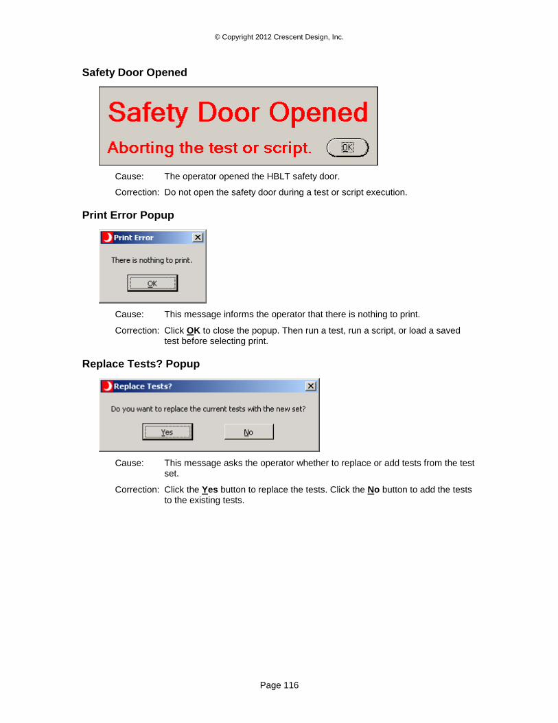
© Copyright 2012 Crescent Design, Inc.
Page 116
Safety Door Opened
Cause: The operator opened the HBLT safety door.
Correction: Do not open the safety door during a test or script execution.
Print Error Popup
Cause: This message informs the operator that there is nothing to print.
Correction: Click OK to close the popup. Then run a test, run a script, or load a saved test before selecting print.
Replace Tests? Popup
Cause: This message asks the operator whether to replace or add tests from the test set.
Correction: Click the Yes button to replace the tests. Click the No button to add the tests to the existing tests.
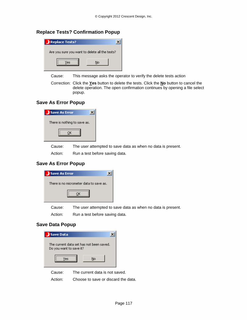
© Copyright 2012 Crescent Design, Inc.
Page 117
Replace Tests? Confirmation Popup
Cause: This message asks the operator to verify the delete tests action
Correction: Click the Yes button to delete the tests. Click the No button to cancel the delete operation. The open confirmation continues by opening a file select popup.
Save As Error Popup
Cause: The user attempted to save data as when no data is present.
Action: Run a test before saving data.
Save As Error Popup
Cause: The user attempted to save data as when no data is present.
Action: Run a test before saving data.
Save Data Popup
Cause: The current data is not saved.
Action: Choose to save or discard the data.
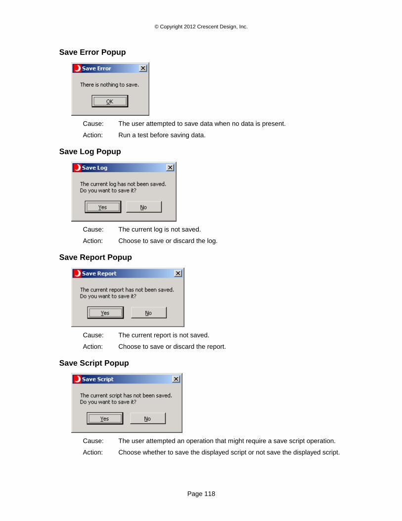
© Copyright 2012 Crescent Design, Inc.
Page 118
Save Error Popup
Cause: The user attempted to save data when no data is present.
Action: Run a test before saving data.
Save Log Popup
Cause: The current log is not saved.
Action: Choose to save or discard the log.
Save Report Popup
Cause: The current report is not saved.
Action: Choose to save or discard the report.
Save Script Popup
Cause: The user attempted an operation that might require a save script operation.
Action: Choose whether to save the displayed script or not save the displayed script.
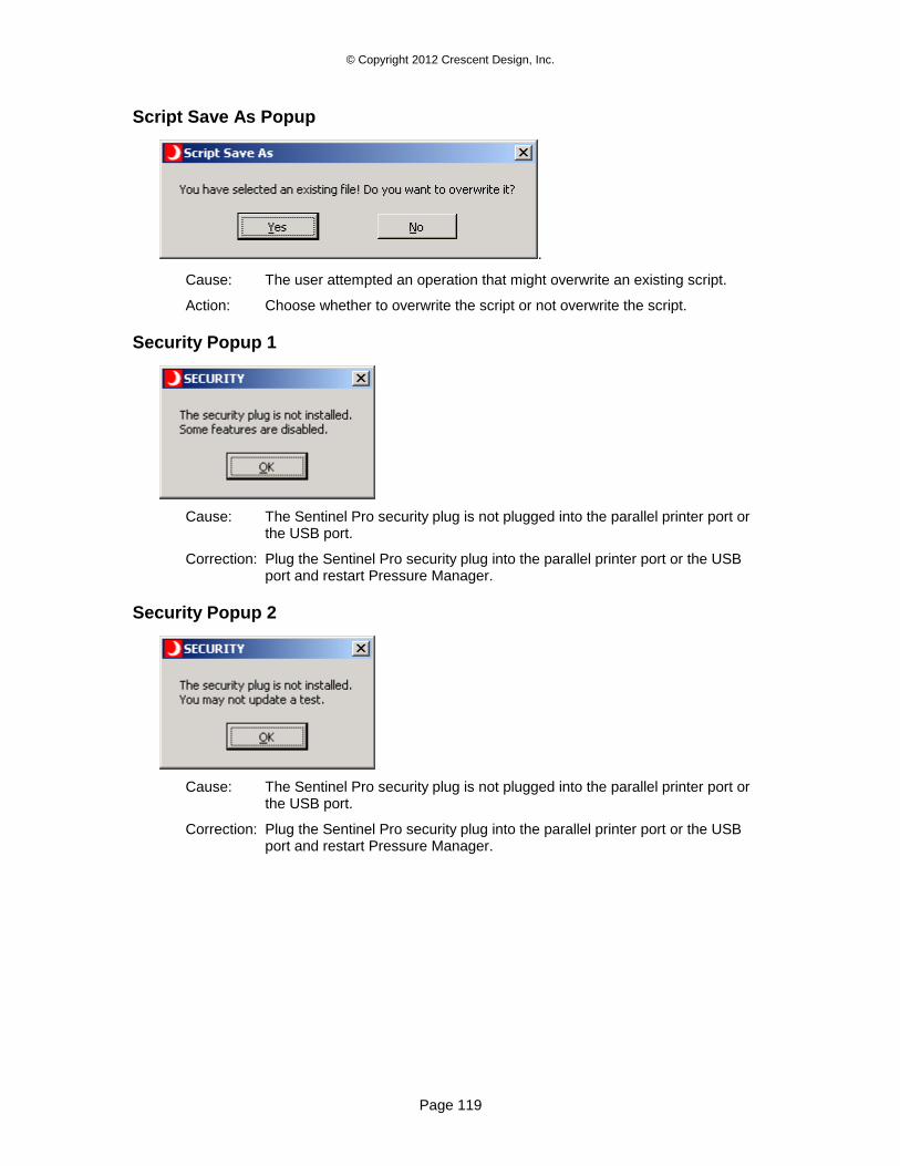
© Copyright 2012 Crescent Design, Inc.
Page 119
Script Save As Popup
.
Cause: The user attempted an operation that might overwrite an existing script.
Action: Choose whether to overwrite the script or not overwrite the script.
Security Popup 1
Cause: The Sentinel Pro security plug is not plugged into the parallel printer port or the USB port.
Correction: Plug the Sentinel Pro security plug into the parallel printer port or the USB port and restart Pressure Manager.
Security Popup 2
Cause: The Sentinel Pro security plug is not plugged into the parallel printer port or the USB port.
Correction: Plug the Sentinel Pro security plug into the parallel printer port or the USB port and restart Pressure Manager.
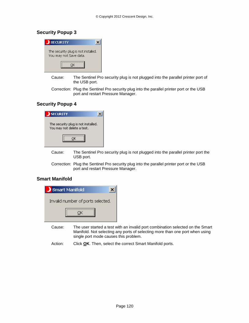
© Copyright 2012 Crescent Design, Inc.
Page 120
Security Popup 3
Cause: The Sentinel Pro security plug is not plugged into the parallel printer port of the USB port.
Correction: Plug the Sentinel Pro security plug into the parallel printer port or the USB port and restart Pressure Manager.
Security Popup 4
Cause: The Sentinel Pro security plug is not plugged into the parallel printer port the USB port.
Correction: Plug the Sentinel Pro security plug into the parallel printer port or the USB port and restart Pressure Manager.
Smart Manifold
Cause: The user started a test with an invalid port combination selected on the Smart Manifold. Not selecting any ports of selecting more than one port when using single port mode causes this problem.
Action: Click OK. Then, select the correct Smart Manifold ports.
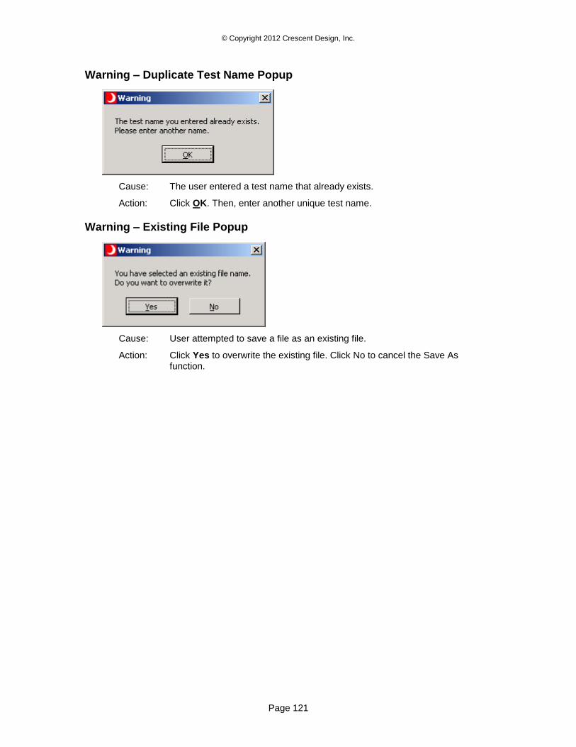
© Copyright 2012 Crescent Design, Inc.
Page 121
Warning – Duplicate Test Name Popup
Cause: The user entered a test name that already exists.
Action: Click OK. Then, enter another unique test name.
Warning – Existing File Popup
Cause: User attempted to save a file as an existing file.
Action: Click Yes to overwrite the existing file. Click No to cancel the Save As function.
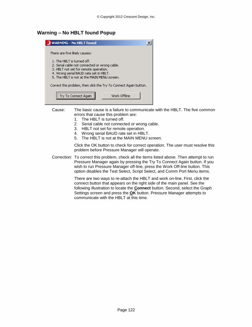
© Copyright 2012 Crescent Design, Inc.
Page 122
Warning – No HBLT found Popup
Cause: The basic cause is a failure to communicate with the HBLT. The five common errors that cause this problem are: 1. The HBLT is turned off. 2. Serial cable not connected or wrong cable. 3. HBLT not set for remote operation. 4. Wrong serial BAUD rate set in HBLT. 5. The HBLT is not at the MAIN MENU screen.
Click the OK button to check for correct operation. The user must resolve this problem before Pressure Manager will operate.
Correction: To correct this problem, check all the items listed above. Then attempt to run Pressure Manager again by pressing the Try To Connect Again button. If you wish to run Pressure Manager off-line, press the Work Off-line button. This option disables the Test Select, Script Select, and Comm Port Menu items.
There are two ways to re-attach the HBLT and work on-line. First, click the connect button that appears on the right side of the main panel. See the
following illustration to locate the Connect button. Second, select the Graph
Settings screen and press the OK button. Pressure Manager attempts to communicate with the HBLT at this time.
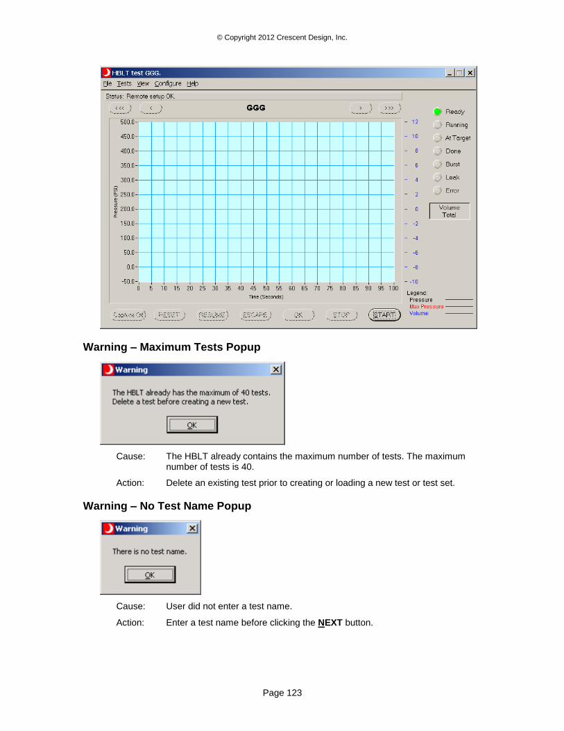
© Copyright 2012 Crescent Design, Inc.
Page 123
Warning – Maximum Tests Popup
Cause: The HBLT already contains the maximum number of tests. The maximum number of tests is 40.
Action: Delete an existing test prior to creating or loading a new test or test set.
Warning – No Test Name Popup
Cause: User did not enter a test name.
Action: Enter a test name before clicking the NEXT button.
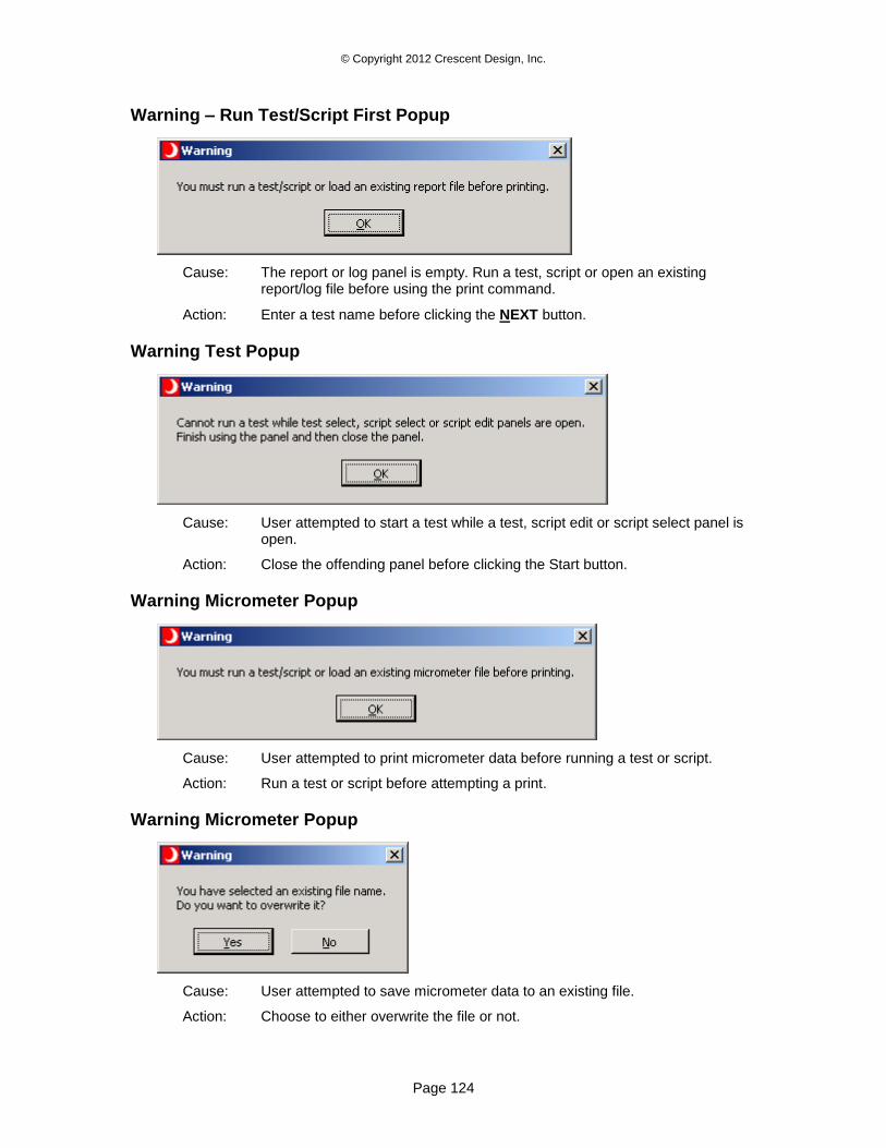
© Copyright 2012 Crescent Design, Inc.
Page 124
Warning – Run Test/Script First Popup
Cause: The report or log panel is empty. Run a test, script or open an existing report/log file before using the print command.
Action: Enter a test name before clicking the NEXT button.
Warning Test Popup
Cause: User attempted to start a test while a test, script edit or script select panel is open.
Action: Close the offending panel before clicking the Start button.
Warning Micrometer Popup
Cause: User attempted to print micrometer data before running a test or script.
Action: Run a test or script before attempting a print.
Warning Micrometer Popup
Cause: User attempted to save micrometer data to an existing file.
Action: Choose to either overwrite the file or not.
© Copyright 2012 Crescent Design, Inc.
Page 125
Appendix A – HBLT Parameter Minimums, Maximums, and
Defaults
The following tables contain the minimums, maximums and defaults for all the pressure parameters. This includes both HBLT native tests and scripts. Each table represents a particular HBLT model. Find the proper table, and then look up the parameter. Finally, find the value in the units column.
Please note that there are relationships between some parameters. Pressure Manager may coerce some parameters into values other than the ones shown here.
With HBLT version 2.47, this version of Pressure Manager uses protocol version 1.45.
In the following tables, a gray field represents a capped parameter. Its value is not the true maximum the machine is capable of producing.
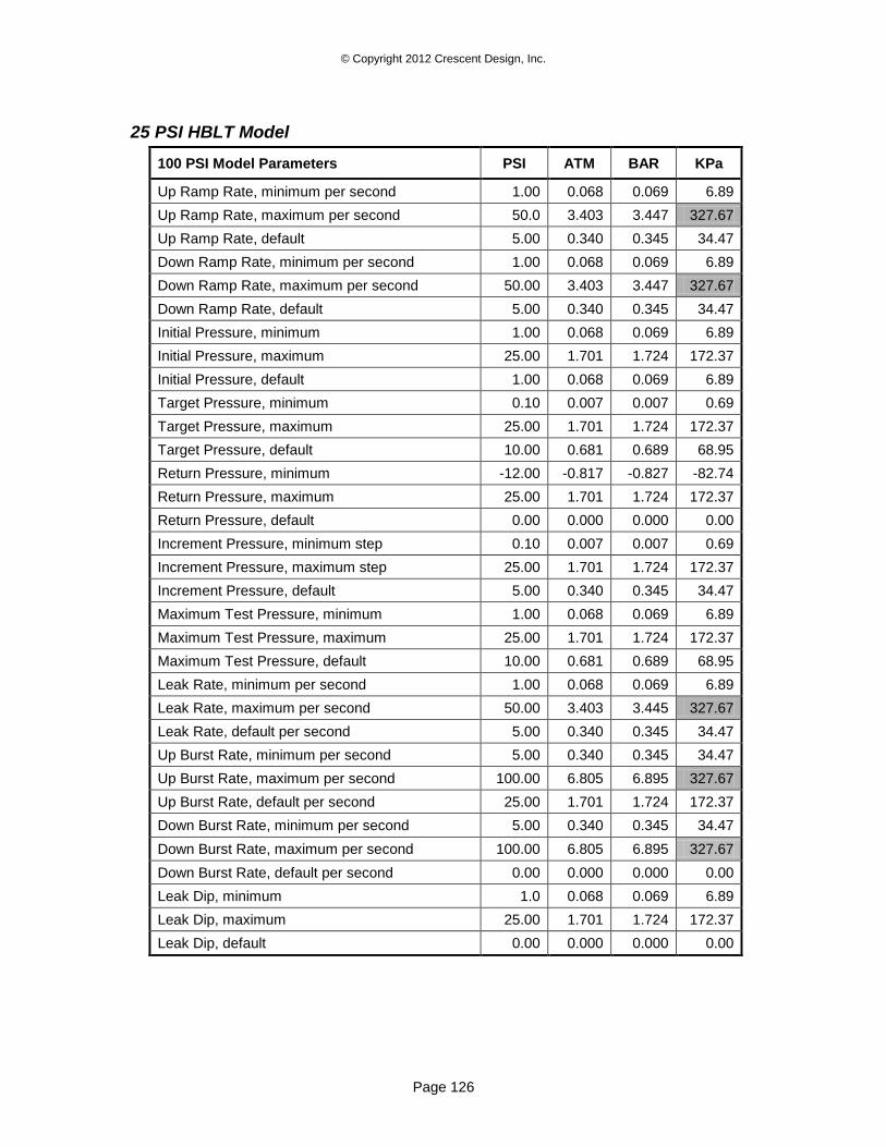
© Copyright 2012 Crescent Design, Inc.
Page 126
25 PSI HBLT Model
100 PSI Model Parameters PSI ATM BAR KPa
Up Ramp Rate, minimum per second 1.00 0.068 0.069 6.89
Up Ramp Rate, maximum per second 50.0 3.403 3.447 327.67
Up Ramp Rate, default 5.00 0.340 0.345 34.47
Down Ramp Rate, minimum per second 1.00 0.068 0.069 6.89
Down Ramp Rate, maximum per second 50.00 3.403 3.447 327.67
Down Ramp Rate, default 5.00 0.340 0.345 34.47
Initial Pressure, minimum 1.00 0.068 0.069 6.89
Initial Pressure, maximum 25.00 1.701 1.724 172.37
Initial Pressure, default 1.00 0.068 0.069 6.89
Target Pressure, minimum 0.10 0.007 0.007 0.69
Target Pressure, maximum 25.00 1.701 1.724 172.37
Target Pressure, default 10.00 0.681 0.689 68.95
Return Pressure, minimum -12.00 -0.817 -0.827 -82.74
Return Pressure, maximum 25.00 1.701 1.724 172.37
Return Pressure, default 0.00 0.000 0.000 0.00
Increment Pressure, minimum step 0.10 0.007 0.007 0.69
Increment Pressure, maximum step 25.00 1.701 1.724 172.37
Increment Pressure, default 5.00 0.340 0.345 34.47
Maximum Test Pressure, minimum 1.00 0.068 0.069 6.89
Maximum Test Pressure, maximum 25.00 1.701 1.724 172.37
Maximum Test Pressure, default 10.00 0.681 0.689 68.95
Leak Rate, minimum per second 1.00 0.068 0.069 6.89
Leak Rate, maximum per second 50.00 3.403 3.445 327.67
Leak Rate, default per second 5.00 0.340 0.345 34.47
Up Burst Rate, minimum per second 5.00 0.340 0.345 34.47
Up Burst Rate, maximum per second 100.00 6.805 6.895 327.67
Up Burst Rate, default per second 25.00 1.701 1.724 172.37
Down Burst Rate, minimum per second 5.00 0.340 0.345 34.47
Down Burst Rate, maximum per second 100.00 6.805 6.895 327.67
Down Burst Rate, default per second 0.00 0.000 0.000 0.00
Leak Dip, minimum 1.0 0.068 0.069 6.89
Leak Dip, maximum 25.00 1.701 1.724 172.37
Leak Dip, default 0.00 0.000 0.000 0.00
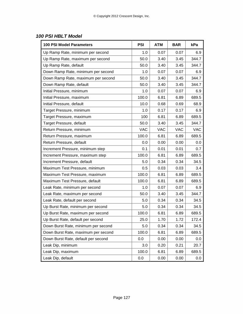
© Copyright 2012 Crescent Design, Inc.
Page 127
100 PSI HBLT Model
100 PSI Model Parameters PSI ATM BAR kPa
Up Ramp Rate, minimum per second 1.0 0.07 0.07 6.9
Up Ramp Rate, maximum per second 50.0 3.40 3.45 344.7
Up Ramp Rate, default 50.0 3.40 3.45 344.7
Down Ramp Rate, minimum per second 1.0 0.07 0.07 6.9
Down Ramp Rate, maximum per second 50.0 3.40 3.45 344.7
Down Ramp Rate, default 50.0 3.40 3.45 344.7
Initial Pressure, minimum 1.0 0.07 0.07 6.9
Initial Pressure, maximum 100.0 6.81 6.89 689.5
Initial Pressure, default 10.0 0.68 0.69 68.9
Target Pressure, minimum 1.0 0.17 0.17 6.9
Target Pressure, maximum 100 6.81 6.89 689.5
Target Pressure, default 50.0 3.40 3.45 344.7
Return Pressure, minimum VAC VAC VAC VAC
Return Pressure, maximum 100.0 6.81 6.89 689.5
Return Pressure, default 0.0 0.00 0.00 0.0
Increment Pressure, minimum step 0.1 0.01 0.01 0.7
Increment Pressure, maximum step 100.0 6.81 6.89 689.5
Increment Pressure, default 5.0 0.34 0.34 34.5
Maximum Test Pressure, minimum 0.5 0.03 0.03 3.4
Maximum Test Pressure, maximum 100.0 6.81 6.89 689.5
Maximum Test Pressure, default 100.0 6.81 6.89 689.5
Leak Rate, minimum per second 1.0 0.07 0.07 6.9
Leak Rate, maximum per second 50.0 3.40 3.45 344.7
Leak Rate, default per second 5.0 0.34 0.34 34.5
Up Burst Rate, minimum per second 5.0 0.34 0.34 34.5
Up Burst Rate, maximum per second 100.0 6.81 6.89 689.5
Up Burst Rate, default per second 25.0 1.70 1.72 172.4
Down Burst Rate, minimum per second 5.0 0.34 0.34 34.5
Down Burst Rate, maximum per second 100.0 6.81 6.89 689.5
Down Burst Rate, default per second 0.0 0.00 0.00 0.0
Leak Dip, minimum 3.0 0.20 0.21 20.7
Leak Dip, maximum 100.0 6.81 6.89 689.5
Leak Dip, default 0.0 0.00 0.00 0.0

© Copyright 2012 Crescent Design, Inc.
Page 128
250 PSI HBLT Model
250 PSI Model Parameters PSI ATM BAR KPa
Up Ramp Rate, minimum per second 1.0 0.07 0.07 7
Up Ramp Rate, maximum per second 125.0 8.51 8.62 862
Up Ramp Rate, default 125.0 8.51 8.62 862
Down Ramp Rate, minimum per second 1.0 0.07 0.07 7
Down Ramp Rate, maximum per second 125.0 8.51 8.62 862
Down Ramp Rate, default 125.0 8.51 8.62 862
Initial Pressure, minimum 1.0 0.07 0.07 7
Initial Pressure, maximum 250.0 17.01 17.24 1724
Initial Pressure, default 25.0 1.70 1.72 172
Target Pressure, minimum 2.5 0.17 0.17 17
Target Pressure, maximum 250.0 17.01 17.24 1724
Target Pressure, default 100.0 6.81 6.89 689
Return Pressure, minimum VAC VAC VAC VAC
Return Pressure, maximum 250.0 17.01 17.24 1724
Return Pressure, default 0.0 0.00 0.00 0
Increment Pressure, minimum step 0.1 0.01 0.01 1
Increment Pressure, maximum step 250.0 17.01 17.24 1724
Increment Pressure, default 10.0 0.68 0.69 69
Maximum Test Pressure, minimum 0.5 0.03 0.03 3
Maximum Test Pressure, maximum 250.0 17.01 17.24 1724
Maximum Test Pressure, default 250.0 17.01 17.24 1724
Leak Rate, minimum per second 1.0 0.07 0.07 7
Leak Rate, maximum per second 50.0 3.40 3.45 345
Leak Rate, default per second 5.0 0.34 0.34 34
Up Burst Rate, minimum per second 5.0 0.34 0.34 34
Up Burst Rate, maximum per second 250.0 17.01 17.24 1724
Up Burst Rate, default per second 25.0 1.70 1.72 172
Down Burst Rate, minimum per second 5.0 0.34 0.34 34
Down Burst Rate, maximum per second 250.0 17.01 17.24 1724
Down Burst Rate, default per second 0.0 0.00 0.00 0
Leak Dip, minimum 3.0 0.20 .021 21
Leak Dip, maximum 250.0 17.01 17.24 1724
Leak Dip, default 0.0 0.00 0.00 0
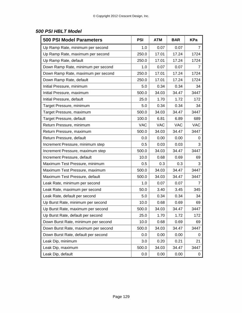
© Copyright 2012 Crescent Design, Inc.
Page 129
500 PSI HBLT Model
500 PSI Model Parameters PSI ATM BAR KPa
Up Ramp Rate, minimum per second 1.0 0.07 0.07 7
Up Ramp Rate, maximum per second 250.0 17.01 17.24 1724
Up Ramp Rate, default 250.0 17.01 17.24 1724
Down Ramp Rate, minimum per second 1.0 0.07 0.07 7
Down Ramp Rate, maximum per second 250.0 17.01 17.24 1724
Down Ramp Rate, default 250.0 17.01 17.24 1724
Initial Pressure, minimum 5.0 0.34 0.34 34
Initial Pressure, maximum 500.0 34.03 34.47 3447
Initial Pressure, default 25.0 1.70 1.72 172
Target Pressure, minimum 5.0 0.34 0.34 34
Target Pressure, maximum 500.0 34.03 34.47 3447
Target Pressure, default 100.0 6.81 6.89 689
Return Pressure, minimum VAC VAC VAC VAC
Return Pressure, maximum 500.0 34.03 34.47 3447
Return Pressure, default 0.0 0.00 0.00 0
Increment Pressure, minimum step 0.5 0.03 0.03 3
Increment Pressure, maximum step 500.0 34.03 34.47 3447
Increment Pressure, default 10.0 0.68 0.69 69
Maximum Test Pressure, minimum 0.5 0.3 0.3 3
Maximum Test Pressure, maximum 500.0 34.03 34.47 3447
Maximum Test Pressure, default 500.0 34.03 34.47 3447
Leak Rate, minimum per second 1.0 0.07 0.07 7
Leak Rate, maximum per second 50.0 3.40 3.45 345
Leak Rate, default per second 5.0 0.34 0.34 34
Up Burst Rate, minimum per second 10.0 0.68 0.69 69
Up Burst Rate, maximum per second 500.0 34.03 34.47 3447
Up Burst Rate, default per second 25.0 1.70 1.72 172
Down Burst Rate, minimum per second 10.0 0.68 0.69 69
Down Burst Rate, maximum per second 500.0 34.03 34.47 3447
Down Burst Rate, default per second 0.0 0.00 0.00 0
Leak Dip, minimum 3.0 0.20 0.21 21
Leak Dip, maximum 500.0 34.03 34.47 3447
Leak Dip, default 0.0 0.00 0.00 0
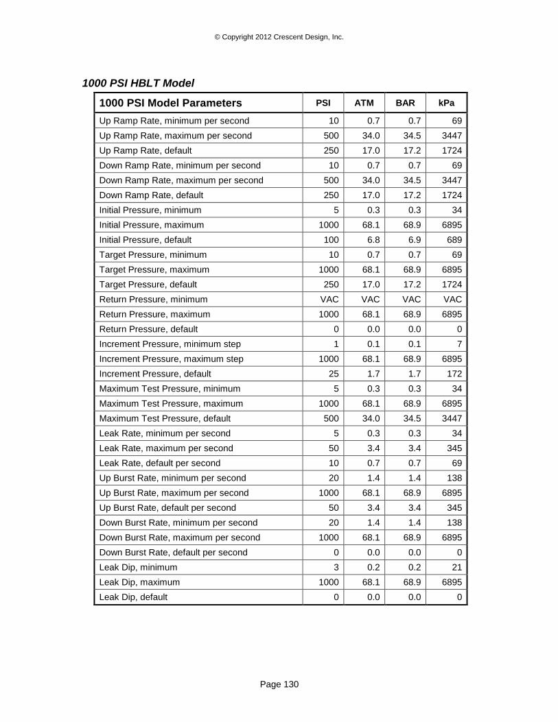
© Copyright 2012 Crescent Design, Inc.
Page 130
1000 PSI HBLT Model
1000 PSI Model Parameters PSI ATM BAR kPa
Up Ramp Rate, minimum per second 10 0.7 0.7 69
Up Ramp Rate, maximum per second 500 34.0 34.5 3447
Up Ramp Rate, default 250 17.0 17.2 1724
Down Ramp Rate, minimum per second 10 0.7 0.7 69
Down Ramp Rate, maximum per second 500 34.0 34.5 3447
Down Ramp Rate, default 250 17.0 17.2 1724
Initial Pressure, minimum 5 0.3 0.3 34
Initial Pressure, maximum 1000 68.1 68.9 6895
Initial Pressure, default 100 6.8 6.9 689
Target Pressure, minimum 10 0.7 0.7 69
Target Pressure, maximum 1000 68.1 68.9 6895
Target Pressure, default 250 17.0 17.2 1724
Return Pressure, minimum VAC VAC VAC VAC
Return Pressure, maximum 1000 68.1 68.9 6895
Return Pressure, default 0 0.0 0.0 0
Increment Pressure, minimum step 1 0.1 0.1 7
Increment Pressure, maximum step 1000 68.1 68.9 6895
Increment Pressure, default 25 1.7 1.7 172
Maximum Test Pressure, minimum 5 0.3 0.3 34
Maximum Test Pressure, maximum 1000 68.1 68.9 6895
Maximum Test Pressure, default 500 34.0 34.5 3447
Leak Rate, minimum per second 5 0.3 0.3 34
Leak Rate, maximum per second 50 3.4 3.4 345
Leak Rate, default per second 10 0.7 0.7 69
Up Burst Rate, minimum per second 20 1.4 1.4 138
Up Burst Rate, maximum per second 1000 68.1 68.9 6895
Up Burst Rate, default per second 50 3.4 3.4 345
Down Burst Rate, minimum per second 20 1.4 1.4 138
Down Burst Rate, maximum per second 1000 68.1 68.9 6895
Down Burst Rate, default per second 0 0.0 0.0 0
Leak Dip, minimum 3 0.2 0.2 21
Leak Dip, maximum 1000 68.1 68.9 6895
Leak Dip, default 0 0.0 0.0 0
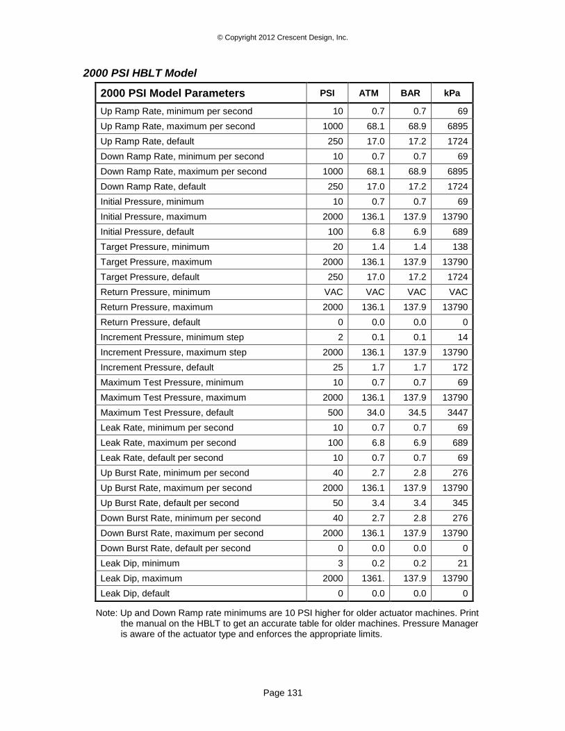
© Copyright 2012 Crescent Design, Inc.
Page 131
2000 PSI HBLT Model
2000 PSI Model Parameters PSI ATM BAR kPa
Up Ramp Rate, minimum per second 10 0.7 0.7 69
Up Ramp Rate, maximum per second 1000 68.1 68.9 6895
Up Ramp Rate, default 250 17.0 17.2 1724
Down Ramp Rate, minimum per second 10 0.7 0.7 69
Down Ramp Rate, maximum per second 1000 68.1 68.9 6895
Down Ramp Rate, default 250 17.0 17.2 1724
Initial Pressure, minimum 10 0.7 0.7 69
Initial Pressure, maximum 2000 136.1 137.9 13790
Initial Pressure, default 100 6.8 6.9 689
Target Pressure, minimum 20 1.4 1.4 138
Target Pressure, maximum 2000 136.1 137.9 13790
Target Pressure, default 250 17.0 17.2 1724
Return Pressure, minimum VAC VAC VAC VAC
Return Pressure, maximum 2000 136.1 137.9 13790
Return Pressure, default 0 0.0 0.0 0
Increment Pressure, minimum step 2 0.1 0.1 14
Increment Pressure, maximum step 2000 136.1 137.9 13790
Increment Pressure, default 25 1.7 1.7 172
Maximum Test Pressure, minimum 10 0.7 0.7 69
Maximum Test Pressure, maximum 2000 136.1 137.9 13790
Maximum Test Pressure, default 500 34.0 34.5 3447
Leak Rate, minimum per second 10 0.7 0.7 69
Leak Rate, maximum per second 100 6.8 6.9 689
Leak Rate, default per second 10 0.7 0.7 69
Up Burst Rate, minimum per second 40 2.7 2.8 276
Up Burst Rate, maximum per second 2000 136.1 137.9 13790
Up Burst Rate, default per second 50 3.4 3.4 345
Down Burst Rate, minimum per second 40 2.7 2.8 276
Down Burst Rate, maximum per second 2000 136.1 137.9 13790
Down Burst Rate, default per second 0 0.0 0.0 0
Leak Dip, minimum 3 0.2 0.2 21
Leak Dip, maximum 2000 1361. 137.9 13790
Leak Dip, default 0 0.0 0.0 0
Note: Up and Down Ramp rate minimums are 10 PSI higher for older actuator machines. Print the manual on the HBLT to get an accurate table for older machines. Pressure Manager is aware of the actuator type and enforces the appropriate limits.
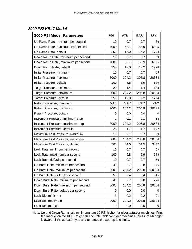
© Copyright 2012 Crescent Design, Inc.
Page 132
3000 PSI HBLT Model
3000 PSI Model Parameters PSI ATM BAR kPa
Up Ramp Rate, minimum per second 10 0.7 0.7 69
Up Ramp Rate, maximum per second 1000 68.1 68.9 6895
Up Ramp Rate, default 250 17.0 17.2 1724
Down Ramp Rate, minimum per second 10 0.7 0.7 69
Down Ramp Rate, maximum per second 1000 68.1 68.9 6895
Down Ramp Rate, default 250 17.0 17.2 1724
Initial Pressure, minimum 10 0.7 0.7 69
Initial Pressure, maximum 3000 204.2 206.8 20684
Initial Pressure, default 100 6.8 6.9 689
Target Pressure, minimum 20 1.4 1.4 138
Target Pressure, maximum 3000 204.2 206.8 20684
Target Pressure, default 250 17.0 17.2 1724
Return Pressure, minimum VAC VAC VAC VAC
Return Pressure, maximum 3000 204.2 206.8 20684
Return Pressure, default 0 0.0 0.0 0
Increment Pressure, minimum step 2 0.1 0.1 14
Increment Pressure, maximum step 3000 204.2 206.8 20684
Increment Pressure, default 25 1.7 1.7 172
Maximum Test Pressure, minimum 10 0.7 0.7 69
Maximum Test Pressure, maximum 3000 204.2 206.8 20684
Maximum Test Pressure, default 500 34.0 34.5 3447
Leak Rate, minimum per second 10 0.7 0.7 69
Leak Rate, maximum per second 100 6.8 6.9 689
Leak Rate, default per second 10 0.7 0.7 69
Up Burst Rate, minimum per second 40 2.7 2.8 276
Up Burst Rate, maximum per second 3000 204.2 206.8 20684
Up Burst Rate, default per second 50 3.4 3.4 345
Down Burst Rate, minimum per second 40 2.7 2.8 276
Down Burst Rate, maximum per second 3000 204.2 206.8 20684
Down Burst Rate, default per second 0 0.0 0.0 0
Leak Dip, minimum 3 0.2 0.2 21
Leak Dip, maximum 3000 204.2 206.8 20684
Leak Dip, default 0 0.0 0.0 0
Note: Up and Down Ramp rate minimums are 10 PSI higher for older actuator machines. Print the manual on the HBLT to get an accurate table for older machines. Pressure Manager is aware of the actuator type and enforces the appropriate limits.
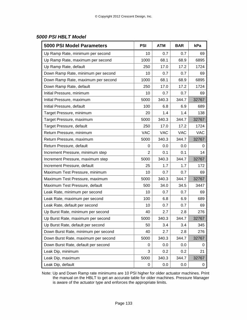
© Copyright 2012 Crescent Design, Inc.
Page 133
5000 PSI HBLT Model
5000 PSI Model Parameters PSI ATM BAR kPa
Up Ramp Rate, minimum per second 10 0.7 0.7 69
Up Ramp Rate, maximum per second 1000 68.1 68.9 6895
Up Ramp Rate, default 250 17.0 17.2 1724
Down Ramp Rate, minimum per second 10 0.7 0.7 69
Down Ramp Rate, maximum per second 1000 68.1 68.9 6895
Down Ramp Rate, default 250 17.0 17.2 1724
Initial Pressure, minimum 10 0.7 0.7 69
Initial Pressure, maximum 5000 340.3 344.7 32767
Initial Pressure, default 100 6.8 6.9 689
Target Pressure, minimum 20 1.4 1.4 138
Target Pressure, maximum 5000 340.3 344.7 32767
Target Pressure, default 250 17.0 17.2 1724
Return Pressure, minimum VAC VAC VAC VAC
Return Pressure, maximum 5000 340.3 344.7 32767
Return Pressure, default 0 0.0 0.0 0
Increment Pressure, minimum step 2 0.1 0.1 14
Increment Pressure, maximum step 5000 340.3 344.7 32767
Increment Pressure, default 25 1.7 1.7 172
Maximum Test Pressure, minimum 10 0.7 0.7 69
Maximum Test Pressure, maximum 5000 340.3 344.7 32767
Maximum Test Pressure, default 500 34.0 34.5 3447
Leak Rate, minimum per second 10 0.7 0.7 69
Leak Rate, maximum per second 100 6.8 6.9 689
Leak Rate, default per second 10 0.7 0.7 69
Up Burst Rate, minimum per second 40 2.7 2.8 276
Up Burst Rate, maximum per second 5000 340.3 344.7 32767
Up Burst Rate, default per second 50 3.4 3.4 345
Down Burst Rate, minimum per second 40 2.7 2.8 276
Down Burst Rate, maximum per second 5000 340.3 344.7 32767
Down Burst Rate, default per second 0 0.0 0.0 0
Leak Dip, minimum 3 0.2 0.2 21
Leak Dip, maximum 5000 340.3 344.7 32767
Leak Dip, default 0 0.0 0.0 0
Note: Up and Down Ramp rate minimums are 10 PSI higher for older actuator machines. Print the manual on the HBLT to get an accurate table for older machines. Pressure Manager is aware of the actuator type and enforces the appropriate limits.
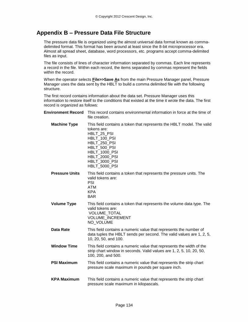
© Copyright 2012 Crescent Design, Inc.
Page 134
Appendix B – Pressure Data File Structure
The pressure data file is organized using the almost universal data format known as comma-delimited format. This format has been around at least since the 8-bit microprocessor era. Almost all spread sheet, database, word processors, etc. programs accept comma-delimited files as input.
The file consists of lines of character information separated by commas. Each line represents a record in the file. Within each record, the items separated by commas represent the fields within the record.
When the operator selects File>>Save As from the main Pressure Manager panel, Pressure Manager uses the data sent by the HBLT to build a comma delimited file with the following structure.
The first record contains information about the data set. Pressure Manager uses this information to restore itself to the conditions that existed at the time it wrote the data. The first record is organized as follows:
Environment Record This record contains environmental information in force at the time of file creation.
Machine Type This field contains a token that represents the HBLT model. The valid tokens are: HBLT_25_PSI HBLT_100_PSI HBLT_250_PSI HBLT_500_PSI HBLT_1000_PSI HBLT_2000_PSI HBLT_3000_PSI HBLT_5000_PSI
Pressure Units This field contains a token that represents the pressure units. The valid tokens are: PSI ATM KPA BAR
Volume Type This field contains a token that represents the volume data type. The valid tokens are: VOLUME_TOTAL VOLUME_INCREMENT NO_VOLUME
Data Rate This field contains a numeric value that represents the number of data tuples the HBLT sends per second. The valid values are 1, 2, 5, 10, 20, 50, and 100.
Window Time This field contains a numeric value that represents the width of the strip chart window in seconds. Valid values are 1, 2, 5, 10, 20, 50, 100, 200, and 500.
PSI Maximum This field contains a numeric value that represents the strip chart pressure scale maximum in pounds per square inch.
KPA Maximum This field contains a numeric value that represents the strip chart pressure scale maximum in kilopascals.
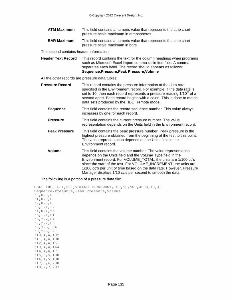
© Copyright 2012 Crescent Design, Inc.
Page 135
ATM Maximum This field contains a numeric value that represents the strip chart pressure scale maximum in atmospheres.
BAR Maximum This field contains a numeric value that represents the strip chart pressure scale maximum in bars.
The second contains header information.
Header Text Record This record contains the text for the column headings when programs such as Microsoft Excel import comma-delimited files. A comma separates each label. The record should appears as follows:
Sequence,Pressure,Peak Pressure,Volume
All the other records are pressure data tuples.
Pressure Record This record contains the pressure information at the data rate specified in the Environment record. For example, if the data rate is set to 10, then each record represents a pressure reading 1/10
th of a
second apart. Each record begins with a colon. This is done to match data sets produced by the HBLT remote mode.
Sequence This field contains the record sequence number. This value always increases by one for each record.
Pressure This field contains the current pressure number. The value representation depends on the Units field in the Environment record.
Peak Pressure This field contains the peak pressure number. Peak pressure is the highest pressure obtained from the beginning of the test to this point. The value representation depends on the Units field in the Environment record.
Volume This field contains the volume number. The value representation depends on the Units field and the Volume Type field in the Environment record. For VOLUME_TOTAL, the units are 1/100 cc's since the start of the test. For VOLUME_INCREMENT, the units are 1/100 cc's per unit of time based on the data rate. However, Pressure Manager displays 1/10 cc's per second to smooth the data.
The following is a portion of a pressure data file:
HBLT_1000_PSI,PSI,VOLUME_INCREMENT,100,50,500,4000,40,40
Sequence,Pressure,Peak Pressure,Volume
:0,0,0,0
:1,0,0,0
:2,0,0,0
:3,1,1,17
:4,0,1,55
:5,1,1,81
:6,2,2,84
:7,2,2,89
:8,3,3,104
:9,2,3,121
:10,4,4,132
:11,4,4,138
:12,4,4,151
:13,4,4,164
:14,4,4,171
:15,5,5,180
:16,4,5,190
:17,6,6,200
:18,7,7,207
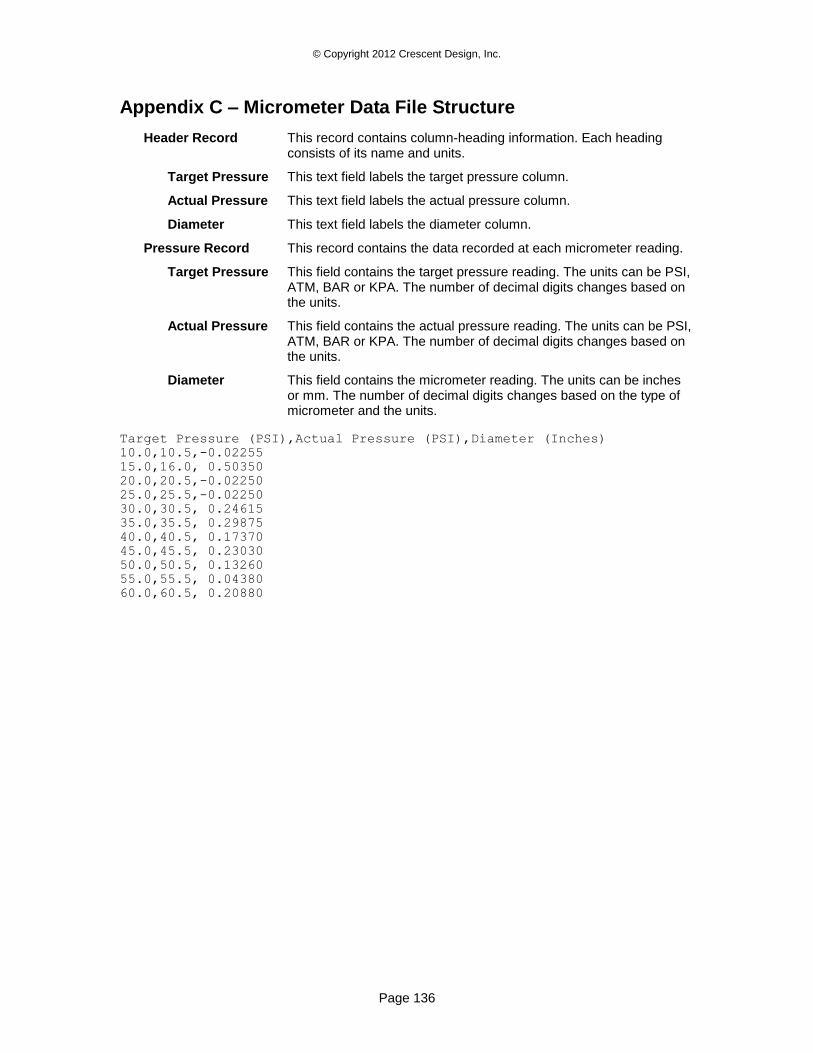
© Copyright 2012 Crescent Design, Inc.
Page 136
Appendix C – Micrometer Data File Structure
Header Record This record contains column-heading information. Each heading consists of its name and units.
Target Pressure This text field labels the target pressure column.
Actual Pressure This text field labels the actual pressure column.
Diameter This text field labels the diameter column.
Pressure Record This record contains the data recorded at each micrometer reading.
Target Pressure This field contains the target pressure reading. The units can be PSI, ATM, BAR or KPA. The number of decimal digits changes based on the units.
Actual Pressure This field contains the actual pressure reading. The units can be PSI, ATM, BAR or KPA. The number of decimal digits changes based on the units.
Diameter This field contains the micrometer reading. The units can be inches or mm. The number of decimal digits changes based on the type of micrometer and the units.
Target Pressure (PSI),Actual Pressure (PSI),Diameter (Inches)
10.0,10.5,-0.02255
15.0,16.0, 0.50350
20.0,20.5,-0.02250
25.0,25.5,-0.02250
30.0,30.5, 0.24615
35.0,35.5, 0.29875
40.0,40.5, 0.17370
45.0,45.5, 0.23030
50.0,50.5, 0.13260
55.0,55.5, 0.04380
60.0,60.5, 0.20880