Embed Size (px)
Citation preview

HC7800DHC7800DW
DLP™ PROJECTORMODEL
HC7800DHC7800DWUser Manual
This User Manual is important to you.Please read it before using your projector.
EN-2
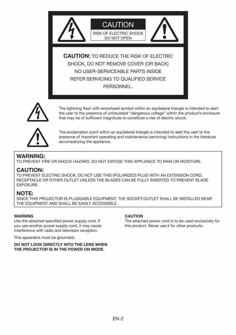
The exclamation point within an equilateral triangle is intended to alert the user to the presence of important operating and maintenance (servicing) instructions in the literature accompanying the appliance.
CAUTIONRISK OF ELECTRIC SHOCK
DO NOT OPEN
CAUTION: TO REDUCE THE RISK OF ELECTRIC
SHOCK, DO NOT REMOVE COVER (OR BACK)
NO USER-SERVICEABLE PARTS INSIDE
REFER SERVICING TO QUALIFIED SERVICE
PERSONNEL.
The lightning flash with arrowhead symbol within an equilateral triangle is intended to alert the user to the presence of uninsulated “dangerous voltage” within the product’s enclosure that may be of sufficient magnitude to constitute a risk of electric shock.
WARNING:TO PREVENT FIRE OR SHOCK HAZARD, DO NOT EXPOSE THIS APPLIANCE TO RAIN OR MOISTURE.
CAUTION:TO PREVENT ELECTRIC SHOCK, DO NOT USE THIS (POLARIZED) PLUG WITH AN EXTENSION CORD, RECEPTACLE OR OTHER OUTLET UNLESS THE BLADES CAN BE FULLY INSERTED TO PREVENT BLADE EXPOSURE.
NOTE:SINCE THIS PROJECTOR IS PLUGGABLE EQUIPMENT, THE SOCKET-OUTLET SHALL BE INSTALLED NEAR THE EQUIPMENT AND SHALL BE EASILY ACCESSIBLE.
WARNING
Use the attached specified power supply cord. If you use another power supply cord, it may cause interference with radio and television reception.
This apparatus must be grounded.
DO NOT LOOK DIRECTLY INTO THE LENS WHEN
THE PROJECTOR IS IN THE POWER ON MODE.
CAUTION
The attached power cord is to be used exclusively for this product. Never use it for other products.
EN-3
Trademark, Registered trademark
Licensing LLC.
Contents
Important safeguards ........................................................................................................................4Preparing your projector ....................................................................................................................6Using the remote control ...................................................................................................................9Setting up your projector .................................................................................................................10Viewing video images ......................................................................................................................14Viewing computer images ...............................................................................................................22Viewing 3D images ..........................................................................................................................25Menu operation ...............................................................................................................................28Adjusting projected images .............................................................................................................36Advanced features ..........................................................................................................................41Initial network settings .....................................................................................................................44Replacing the lamp .........................................................................................................................48Maintenance ....................................................................................................................................51Troubleshooting ...............................................................................................................................52Indicators .........................................................................................................................................57Specifications ..................................................................................................................................58
EN-4
Important safeguards
Please read all these instructions regarding your projector and retain them for future reference. Follow all warnings and instructions marked on the projector.
1. Read instructions All the safety and operating instructions should be
read before the appliance is operated.
2. Retain instructions The safety and operating instructions should be
retained for future reference.
3. Warnings All warnings on the appliance and in the operating
instructions should be adhered to.
4. Instructions All operating instructions must be followed.
5. Cleaning Unplug this projector from the wall outlet before
cleaning it. Do not use liquid aerosol cleaners. Use a damp soft cloth for cleaning.
6. Attachments and equipment Never add any attachments and/or equipment
without the approval of the manufacturer as such additions may result in the risk of fire, electric shock or other personal injury.
7. Water and moisture Do not use this projector near water or in contact
with water.
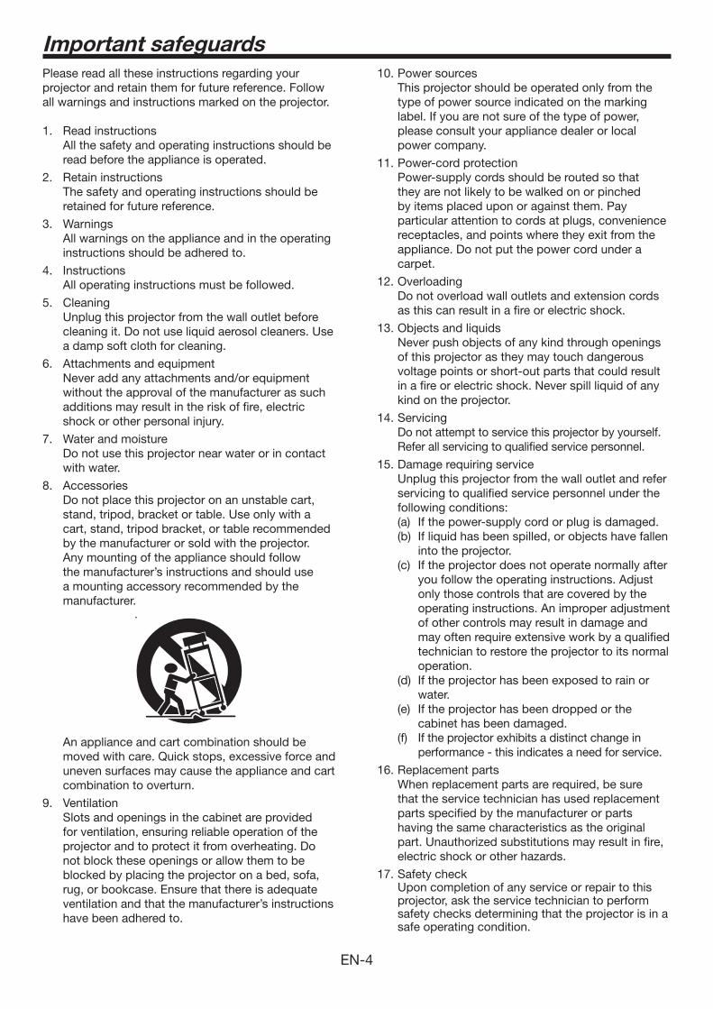
8. Accessories Do not place this projector on an unstable cart,
stand, tripod, bracket or table. Use only with a cart, stand, tripod bracket, or table recommended by the manufacturer or sold with the projector. Any mounting of the appliance should follow the manufacturer’s instructions and should use a mounting accessory recommended by the manufacturer.
An appliance and cart combination should be moved with care. Quick stops, excessive force and uneven surfaces may cause the appliance and cart combination to overturn.
9. Ventilation Slots and openings in the cabinet are provided
for ventilation, ensuring reliable operation of the projector and to protect it from overheating. Do not block these openings or allow them to be blocked by placing the projector on a bed, sofa, rug, or bookcase. Ensure that there is adequate ventilation and that the manufacturer’s instructions have been adhered to.
10. Power sources This projector should be operated only from the
type of power source indicated on the marking label. If you are not sure of the type of power, please consult your appliance dealer or local power company.
11. Power-cord protection Power-supply cords should be routed so that
they are not likely to be walked on or pinched by items placed upon or against them. Pay particular attention to cords at plugs, convenience receptacles, and points where they exit from the appliance. Do not put the power cord under a carpet.
12. Overloading Do not overload wall outlets and extension cords
as this can result in a fire or electric shock.
13. Objects and liquids Never push objects of any kind through openings
of this projector as they may touch dangerous voltage points or short-out parts that could result in a fire or electric shock. Never spill liquid of any kind on the projector.
14. Servicing Do not attempt to service this projector by yourself.
Refer all servicing to qualified service personnel.
15. Damage requiring service Unplug this projector from the wall outlet and refer
servicing to qualified service personnel under the following conditions:(a) If the power-supply cord or plug is damaged.(b) If liquid has been spilled, or objects have fallen
into the projector.(c) If the projector does not operate normally after
you follow the operating instructions. Adjust only those controls that are covered by the operating instructions. An improper adjustment of other controls may result in damage and may often require extensive work by a qualified technician to restore the projector to its normal operation.
(d) If the projector has been exposed to rain or water.
(e) If the projector has been dropped or the cabinet has been damaged.
(f) If the projector exhibits a distinct change in performance - this indicates a need for service.
16. Replacement parts When replacement parts are required, be sure
that the service technician has used replacement parts specified by the manufacturer or parts having the same characteristics as the original part. Unauthorized substitutions may result in fire, electric shock or other hazards.
17. Safety check Upon completion of any service or repair to this
projector, ask the service technician to perform safety checks determining that the projector is in a safe operating condition.

EN-5
WARNING:
Unplug immediately if there is something wrong with your projector.Do not operate if smoke, strange noise or odor comes out of your projector. It might cause fire or electric shock. In this case, unplug immediately and contact your dealer.Never remove the cabinet.This projector contains high voltage circuitry. An inadvertent contact may result in an electric shock. Except as specifically explained in the User Manual do not attempt to service this product by yourself. Please contact your dealer when you want to fix, adjust or inspect the projector.Do not modify this equipment.It can lead to fire or electric shock.Do not keep using the damaged projector.If the projector is dropped and the cabinet is damaged, unplug the projector and contact your dealer for inspection. It may lead to fire if you keep using the damaged projector.Be sure to unplug the power cord from the wall outlet if the projector is fractured or deformed.Otherwise, it may result in fire or electric shock. Ask your dealer for repair.Do not face the projector lens to the sun.It can lead to fire.Use correct voltage.If you use incorrect voltage, it can lead to fire.Do not place the projector on uneven surface.Place the projection on a leveled and stable surface only. Please do not place equipment on unstable surfaces.Do not look into the lens when it is operating.It may hurt your eyes. Never let children look into the lens when it is on.Do not unplug the power cord during operation.It can lead to lamp breakage, fire, electric shock or other trouble. It is best to wait for the fan to turn off before turning the main power off.Do not touch the air outlet grille and bottom plate, which become hot.Do not touch them or put other equipment in front of the air outlet grille. The air outlet grille and bottom plate, when heated, may cause injury or damage to other equipment. Also, do not set the projector on the desk which is easily affected by heat.Do not look into the air outlet grille when projector is operating.Heat, dust, etc. may blow out of it and hurt your eyes.Do not block the air inlet and outlet grilles.If they are blocked, heat may be generated inside the projector, causing deterioration in the projector quality and fire.Do not use flammable solvents (benzene, thinner, etc.) and flammable aerosols near the projector.Flammable substances may ignite causing fire or breakdown because the temperature inside the projector rises very high while the lamp is illuminating.
Do not use the projector with condensation on it. It can lead to breakdown or other failure. Place of installationFor safety’s sake, refrain from setting the projector at any place subjected to high temperature and high humidity. Please maintain an operating temperature, humidity, and altitude as specified below.
projector so that the projector does not overheat.
or subjected to vibration.
produces a strong magnetic field. Also refrain from installing near the projector any cable carrying a large current.
otherwise it may fall, causing serious injury to a child or adult, and serious damage to the product.
injury and damage to the projector.
the lamp.
heater, or humidifier to avoid hot or moist air to the exhaust and ventilation hole of the projector.
Otherwise, a short circuit, heat generation, or melting of the power cord coating may occur, causing fire, electric shock, product failure, or deformation.
generated (i.e. hot spring)
the coastDo not place a container containing water or other liquid on the projector.If water spills on or enters the projector, it may result in fire or electric shock.Do not put any object that is heavy or larger than the outer frame on the projector.Otherwise, the object may fall losing its balance and cause injury.Do not subject the projector to strong shocks or vibrations. Do not handle the projector roughly.The projector may be damaged, resulting in fire or electric shock.
Important safeguards (continued)
EN-6
What’s included in the box
AC power cord* for US J2552-0063-03 for EU J2552-0247-00 for UK J2552-0065-02 for Australia J2552-0053-00 for South Korea J2552-0247-00Computer cable J2552-0072-05Mini DIN 5-pin cable J2552-0376-00
Remote controlUser Manual/Quick Start up (English only)Safety Manual/Quick Start upCD-ROM (with User Manual)Battery (2)Lens capLamp replacement attachment3D emitterNon-slip sheet3D emitter securing screw (2)
* One of power cords for the U.S., Europe, U.K., Australia, and South Korea is provided appropriately.
Important:
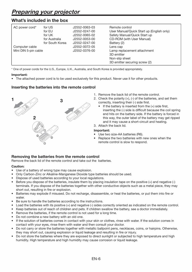
Inserting the batteries into the remote control
1. Remove the back lid of the remote control.
correctly, inserting their (-) side first.
inserting the (-) side is difficult because the coil spring end hits on the battery side. If the battery is forced in this way, the outer label of the battery may get ripped and it may cause a short-circuit and heating.
3. Attach the back lid.
Important:
remote control is slow to respond.
Removing the batteries from the remote controlRemove the back lid of the remote control and take out the batteries.
Caution:
terminals. If you dispose of the batteries together with other conductive objects such as a metal piece, they may short out, resulting in fire or explosion.
water.
contact with your eyes, rinse them with water and then consult your doctor.
they may short out, causing explosion or liquid leakage and resulting in fire or injury.
humidity. High temperature and high humidity may cause corrosion or liquid leakage.
Preparing your projector
2
31
EN-7
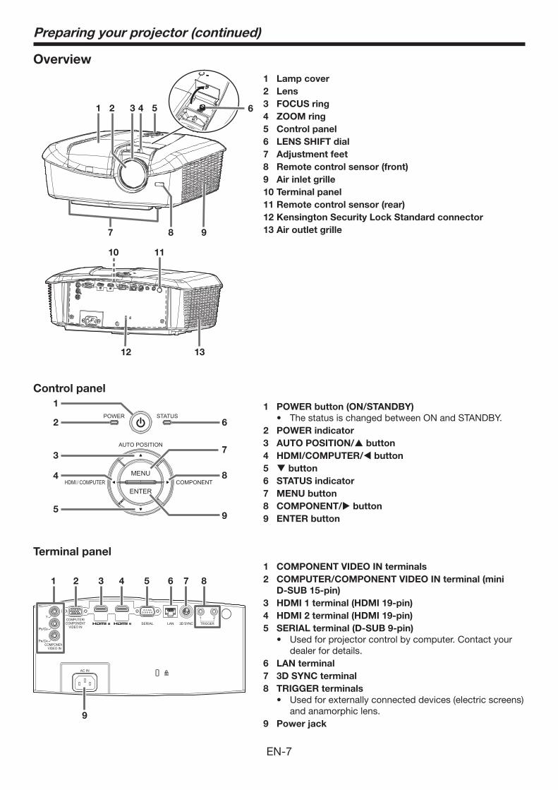
Overview
1 COMPONENT VIDEO IN terminals
2 COMPUTER/COMPONENT VIDEO IN terminal (mini
D-SUB 15-pin)
3 HDMI 1 terminal (HDMI 19-pin)
4 HDMI 2 terminal (HDMI 19-pin)
5 SERIAL terminal (D-SUB 9-pin)
dealer for details.6 LAN terminal
7 3D SYNC terminal
8 TRIGGER terminals
and anamorphic lens.9 Power jack
1 POWER button (ON/STANDBY)
2 POWER indicator
3 AUTO POSITION/ button
4 HDMI/COMPUTER/ button
5 button
6 STATUS indicator
7 MENU button
8 COMPONENT/ button
9 ENTER button
1 Lamp cover
2 Lens
3 FOCUS ring
4 ZOOM ring
5 Control panel
6 LENS SHIFT dial
7 Adjustment feet
8 Remote control sensor (front)
9 Air inlet grille
10 Terminal panel
11 Remote control sensor (rear)
12 Kensington Security Lock Standard connector
13 Air outlet grille
Terminal panel
Control panel
Preparing your projector (continued)
1 5 6
9
432
10 11
87
12 13
1
2 6
8
9
3
4
5
7
1 2 3 4 6 8
9
5 7
EN-8
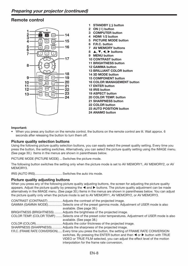
Remote control1 STANDBY ( ) button
2 ON ( I ) button
3 COMPUTER button
4 HDMI 1/2 button
5 PICTURE MODE button
6 F.R.C. button
7 AV MEMORY buttons
8 , , , buttons
9 MENU button
10 CONTRAST button
11 BRIGHTNESS button
12 GAMMA button
13 BRILLIANT COLOR button
14 3D MODE button
15 COMPONENT button
16 COLOR MANAGEMENT button
17 ENTER button
18 IRIS button
19 ASPECT button
20 COLOR TEMP. button
21 SHARPNESS button
22 COLOR button
23 AUTO POSITION button
24 ANAMO button
Preparing your projector (continued)
19
2021222324
17
14
18
16
15
1234
567
8
9
101112
13
Important:
seconds after releasing the button to turn them off.
Picture quality selection buttonsUsing the following picture quality selection buttons, you can easily select the preset quality setting. Every time you press the button, the setting switches. Alternatively, you can select the picture quality setting using the IMAGE menu. (See page 30.) Items in the menus are shown in parentheses below.
PICTURE MODE (PICTURE MODE) ... Switches the picture mode.
The following button switches the setting only when the picture mode is set to AV MEMORY1, AV MEMORY2, or AV MEMORY3.
IRIS (AUTO IRIS) ............................... Switches the auto iris mode.
Picture quality adjusting buttonsWhen you press any of the following picture quality adjusting buttons, the screen for adjusting the picture quality appears. Adjust the picture quality by pressing the and buttons. The picture quality adjustment can be made alternatively in the IMAGE menu. (See page 30.) Items in the menus are shown in parentheses below. You can adjust the picture quality only when the picture mode is set to AV MEMORY1, AV MEMORY2, or AV MEMORY3.
CONTRAST (CONTRAST) ................ Adjusts the contrast of the projected image.GAMMA (GAMMA MODE) ................ Selects one of the preset gamma mode. Adjustment of USER mode is also
available. (See page 39.)BRIGHTNESS (BRIGHTNESS) ......... Adjusts the brightness of the projected image.COLOR TEMP. (COLOR TEMP.) ....... Selects one of the preset color temperatures. Adjustment of USER mode is also
available. (See page 38.)COLOR (COLOR) .............................. Adjusts the color thickness of the projected image.SHARPNESS (SHARPNESS) ............ Adjusts the sharpness of the projected image.F.R.C. (FRAME RATE CONVERSION) ..... Every time you press the button, the setting of FRAME RATE CONVERSION
switches. By pressing the ENTER button and then or button with TRUE VIDEO or TRUE FILM selected, you can adjust the effect level of the motion interpolation for the frame rate conversion.
EN-9
30303030
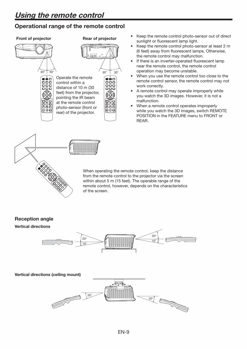
Operational range of the remote control
Vertical directions (ceiling mount)
Reception angle
Vertical directions
When operating the remote control, keep the distance from the remote control to the projector via the screen within about 5 m (15 feet). The operable range of the remote control, however, depends on the characteristics of the screen.
Operate the remote control within a distance of 10 m (30 feet) from the projector, pointing the IR beam at the remote control photo-sensor (front or rear) of the projector.
sunlight or fluorescent lamp light.
(6 feet) away from fluorescent lamps. Otherwise, the remote control may malfunction.
near the remote control, the remote control operation may become unstable.
remote control sensor, the remote control may not work correctly.
you watch the 3D images. However, it is not a malfunction.
while you watch the 3D images, switch REMOTE POSITION in the FEATURE menu to FRONT or REAR.
Front of projector Rear of projector
Using the remote control
20°
10°
20°
10˚
20
EN-10
Setting up your projector
Setting up the screenInstall the screen perpendicularly to the projector. If the screen can not be installed in such a way, adjust the projection angle of the projector. (See page 12.)
the screen center.
makes the projected images washed-out and hard to view.
SCREEN SIZEYou can keep the image display area within the screen by setting SCREEN SIZE in the ADVANCED MENU of IMAGE menu according to the aspect ratio of the actual screen. Select 16:9 when the aspect ratio of the screen is 16:9 or 4:3, and select CINEMA SCOPE (2.35:1) when the aspect ratio is 2.35:1 (CinemaScope).When setting SCREEN SIZE to CINEMA SCOPE (2.35:1):
horizontally.
for displaying subtitles is not projected. To display subtitles, reset SCREEN SIZE to 16:9 and adjust the image position using VERTICAL LOCATION in the ADVANCED MENU of the IMAGE menu. (To display the menu on the screen, adjust SHUTTER(U) in the SIGNAL - USER menu to position the menu.)
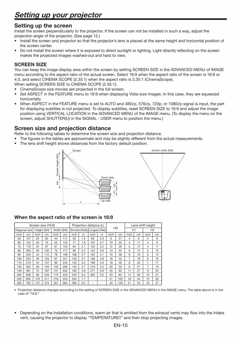
Screen size and projection distanceRefer to the following tables to determine the screen size and projection distance.
Screen width (SW)
Down side
Up side
Screen
Scr
een
heig
ht (S
H)
Hd
H2
H1
L
When the aspect ratio of the screen is 16:9
Screen size (16:9) Projection distance (L)Hd
Lens shift heightDiagonal size Height (SH) Width (SW) Shortest (Wide) Longest (Tele) H1 H2
inch cm inch cm inch cm inch m inch m inch cm inch cm inch cm50 127 25 62 44 111 59 1.5 89 2.3 8 21 4 9 3 8 60 152 29 75 52 133 71 1.8 107 2.7 10 25 4 11 4 9 70 178 34 87 61 155 84 2.1 125 3.2 12 29 5 12 4 11 80 203 39 100 70 177 96 2.4 144 3.6 13 34 6 14 5 12 90 229 44 112 78 199 108 2.7 162 4.1 15 38 6 16 6 14 100 254 49 125 87 221 120 3.1 180 4.6 16 42 7 18 6 16 110 279 54 137 96 244 133 3.4 198 5.0 18 46 8 20 7 17 120 305 59 149 105 266 145 3.7 216 5.5 20 50 8 21 7 19 150 381 74 187 131 332 182 4.6 271 6.9 25 63 11 27 9 23 200 508 98 249 174 443 243 6.2 362 9.2 33 84 14 36 12 31 250 635 123 311 218 553 304 7.7 - - 41 105 18 45 15 39 300 762 147 374 261 664 365 9.3 - - 49 126 21 54 18 47
case of “16:9.”
vent, causing the projector to display “TEMPERATURE!!” and then stop projecting images.
EN-11
Setting up your projector (continued)
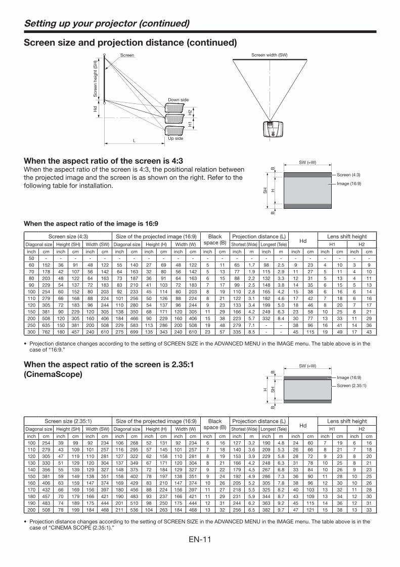
Screen size and projection distance (continued)
Screen width (SW)
Down side
Up side
Screen
Scr
een
heig
ht (S
H)
Hd
H2
H1
L
When the aspect ratio of the screen is 4:3When the aspect ratio of the screen is 4:3, the positional relation between the projected image and the screen is as shown on the right. Refer to the following table for installation.
Screen (4:3)
Image (16:9)
BB
HSH
SW (=W)
When the aspect ratio of the image is 16:9
Screen size (4:3) Size of the projected image (16:9) Black space (B)
Projection distance (L)Hd
Lens shift heightDiagonal size Height (SH) Width (SW) Diagonal size Height (H) Width (W) Shortest (Wide) Longest (Tele) H1 H2
inch cm inch cm inch cm inch cm inch cm inch cm inch cm inch m inch m inch cm inch cm inch cm50 - - - - - - - - - - - - - - - - - - - - - - -60 152 36 91 48 122 55 140 27 69 48 122 5 11 65 1.7 98 2.5 9 23 4 10 3 9 70 178 42 107 56 142 64 163 32 80 56 142 5 13 77 1.9 115 2.9 11 27 5 11 4 10 80 203 48 122 64 163 73 187 36 91 64 163 6 15 88 2.2 132 3.3 12 31 5 13 4 11 90 229 54 137 72 183 83 210 41 103 72 183 7 17 99 2.5 148 3.8 14 35 6 15 5 13 100 254 60 152 80 203 92 233 45 114 80 203 8 19 110 2.8 165 4.2 15 38 6 16 6 14 110 279 66 168 88 224 101 256 50 126 88 224 8 21 122 3.1 182 4.6 17 42 7 18 6 16 120 305 72 183 96 244 110 280 54 137 96 244 9 23 133 3.4 199 5.0 18 46 8 20 7 17 150 381 90 229 120 305 138 350 68 171 120 305 11 29 166 4.2 249 6.3 23 58 10 25 8 21 200 508 120 305 160 406 184 466 90 229 160 406 15 38 223 5.7 332 8.4 30 77 13 33 11 29 250 635 150 381 200 508 229 583 113 286 200 508 19 48 279 7.1 - - 38 96 16 41 14 36 300 762 180 457 240 610 275 699 135 343 240 610 23 57 335 8.5 - - 45 115 19 49 17 43
case of “16:9.”
When the aspect ratio of the screen is 2.35:1
(CinemaScope)
Screen (2.35:1)
Image (16:9)
BB
SHH
SW (=W)
Screen size (2.35:1) Size of the projected image (16:9) Black space (B)
Projection distance (L)Hd
Lens shift heightDiagonal size Height (SH) Width (SW) Diagonal size Height (H) Width (W) Shortest (Wide) Longest (Tele) H1 H2
inch cm inch cm inch cm inch cm inch cm inch cm inch cm inch m inch m inch cm inch cm inch cm100 254 39 99 92 234 106 268 52 131 92 234 6 16 127 3.2 190 4.8 24 60 7 19 6 16 110 279 43 109 101 257 116 295 57 145 101 257 7 18 140 3.6 209 5.3 26 66 8 21 7 18 120 305 47 119 110 281 127 322 62 158 110 281 8 19 153 3.9 229 5.8 28 72 9 23 8 20 130 330 51 129 120 304 137 349 67 171 120 304 8 21 166 4.2 248 6.3 31 78 10 25 8 21 140 356 55 139 129 327 148 375 72 184 129 327 9 22 179 4.5 267 6.8 33 84 10 26 9 23 150 381 59 149 138 351 158 402 78 197 138 351 9 24 192 4.9 286 7.3 36 90 11 28 10 25 160 406 63 159 147 374 169 429 83 210 147 374 10 26 205 5.2 305 7.8 38 96 12 30 10 26 170 432 66 169 156 397 180 456 88 224 156 397 11 27 218 5.5 325 8.2 40 103 13 32 11 28 180 457 70 179 166 421 190 483 93 237 166 421 11 29 231 5.9 344 8.7 43 109 13 34 12 30 190 483 74 189 175 444 201 510 98 250 175 444 12 31 244 6.2 363 9.2 45 115 14 36 12 31 200 508 78 199 184 468 211 536 104 263 184 468 13 32 256 6.5 382 9.7 47 121 15 38 13 33
case of “CINEMA SCOPE (2.35:1).”
EN-12
Adjusting the position of the projected imageTo adjust the position of the projected image on the screen, use the LENS SHIFT dial.
1. Rotate the LENS SHIFT dial inside the top cover of the projector to adjust the image position.
positioned close to the top (or bottom in the case of a ceiling-mount projector).
Correcting skewed or distorted imageFor the best projection, project images on a flat screen installed at 90 degrees to the floor. If necessary, tilt the projector using the two adjustment feet on the bottom of the projector.
1. Tilt up the projector to the appropriate angle.
2. Rotate the adjustment feet for fine adjustment.
Important:
adjustment feet may be damaged.
When fine streaks are seen on projected imagesThis is due to interference with the screen surface and is not a malfunction. Replace the screen or displace the focus a little. (See page 18 or 23 for focus adjustment.)
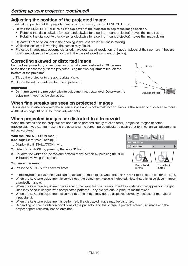
When projected images are distorted to a trapezoidWhen the screen and the projector are not placed perpendicularly to each other, projected images become trapezoidal. If you cannot make the projector and the screen perpendicular to each other by mechanical adjustments, adjust keystone.
With the INSTALLATION menu:
(See page 29 for menu setting.)
1. Display the INSTALLATION menu.
2. Select KEYSTONE by pressing the or button.
3. Equalize the widths at the top and bottom of the screen by pressing the or button, viewing the screen.
To cancel the menu:
4. Press the MENU button several times.
a projection angle.
lines may bend in images with complicated patterns. They are not due to product malfunctions.
input signal.
Depending on the installation conditions of the projector and the screen, a perfect rectangular image and the proper aspect ratio may not be obtained.
Setting up your projector (continued)
INSTALLATION
KEYSTONE 0
opt.
Press the button.
Press the button.
Adjustment feet
Screen
EN-13
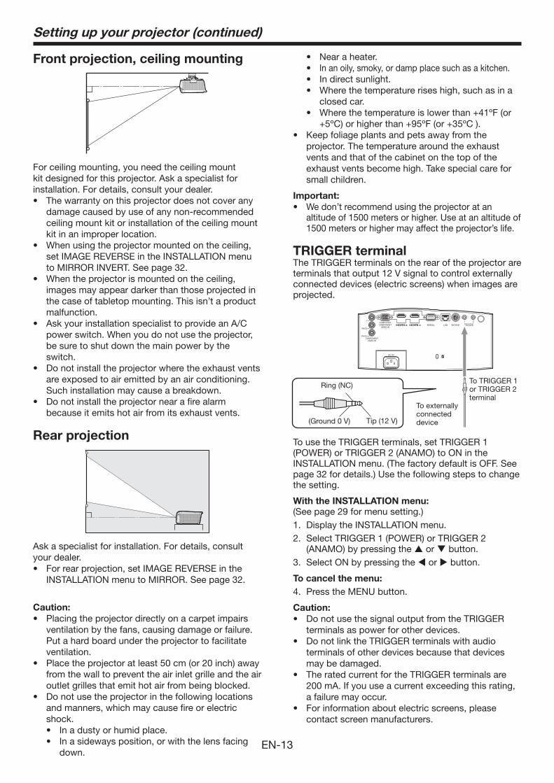
Front projection, ceiling mounting
For ceiling mounting, you need the ceiling mount kit designed for this projector. Ask a specialist for installation. For details, consult your dealer.
damage caused by use of any non-recommended ceiling mount kit or installation of the ceiling mount kit in an improper location.
set IMAGE REVERSE in the INSTALLATION menu to MIRROR INVERT. See page 32.
images may appear darker than those projected in the case of tabletop mounting. This isn’t a product malfunction.
power switch. When you do not use the projector, be sure to shut down the main power by the switch.
are exposed to air emitted by an air conditioning. Such installation may cause a breakdown.
because it emits hot air from its exhaust vents.
Rear projection
Ask a specialist for installation. For details, consult your dealer.
INSTALLATION menu to MIRROR. See page 32.
Caution:
ventilation by the fans, causing damage or failure. Put a hard board under the projector to facilitate ventilation.
from the wall to prevent the air inlet grille and the air outlet grilles that emit hot air from being blocked.
and manners, which may cause fire or electric shock.
down.
Setting up your projector (continued)
In an oily, smoky, or damp place such as a kitchen.
closed car.
projector. The temperature around the exhaust vents and that of the cabinet on the top of the exhaust vents become high. Take special care for small children.
Important:
We don’t recommend using the projector at an altitude of 1500 meters or higher. Use at an altitude of 1500 meters or higher may affect the projector’s life.
TRIGGER terminalThe TRIGGER terminals on the rear of the projector are terminals that output 12 V signal to control externally connected devices (electric screens) when images are projected.
Ring (NC)
To externally connected device Tip (12 V)(Ground 0 V)
To TRIGGER 1 or TRIGGER 2 terminal
To use the TRIGGER terminals, set TRIGGER 1 (POWER) or TRIGGER 2 (ANAMO) to ON in the INSTALLATION menu. (The factory default is OFF. See page 32 for details.) Use the following steps to change the setting.
With the INSTALLATION menu:
(See page 29 for menu setting.)1. Display the INSTALLATION menu.2. Select TRIGGER 1 (POWER) or TRIGGER 2
(ANAMO) by pressing the or button.3. Select ON by pressing the or button.
To cancel the menu:
4. Press the MENU button.
Caution:
terminals as power for other devices.
terminals of other devices because that devices may be damaged.
200 mA. If you use a current exceeding this rating, a failure may occur.
contact screen manufacturers.
EN-14
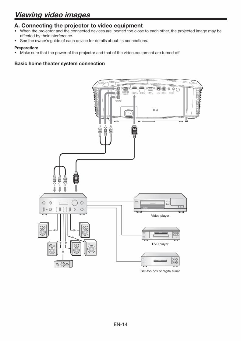
A. Connecting the projector to video equipment
affected by their interference.
Preparation:
Basic home theater system connection
DVD player
Video player
Set-top box or digital tuner
Viewing video images
EN-15
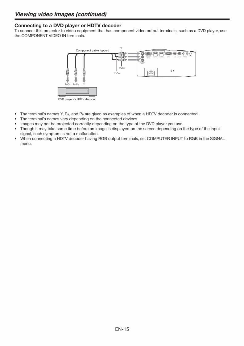
Connecting to a DVD player or HDTV decoderTo connect this projector to video equipment that has component video output terminals, such as a DVD player, use the COMPONENT VIDEO IN terminals.
B, and PR are given as examples of when a HDTV decoder is connected.
signal, such symptom is not a malfunction.
menu.
PB/CB Y PR/CR
PB/CB
Y
PR/CR
Y Component cable (option)
DVD player or HDTV decoder
Viewing video images (continued)
EN-16
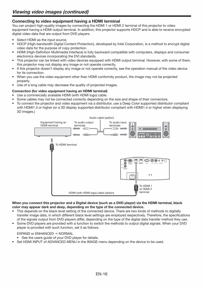
Connecting to video equipment having a HDMI terminalYou can project high-quality images by connecting the HDMI 1 or HDMI 2 terminal of this projector to video equipment having a HDMI output terminal. In addition, this projector supports HDCP and is able to receive encrypted digital video data that are output from DVD players.
video data for the purpose of copy protection.
electronics devices incorporating the DVI standards.
this projector may not display any image or not operate correctly.
for its connection.
properly.
Connection (for video equipment having an HDMI terminal)
with HDMI1.3 or higher (or a 3D display supported distributor compliant with HDMI1.4 or higher when displaying 3D images.)
Equipment having an HDMI terminal
To HDMI terminal
To HDMI 1 or HDMI 2 terminal
To audio input terminals
To audio output terminals
Audio cable (option)
HDMI (with HDMI logo) cable (option)
When you connect this projector and a Digital device (such as a DVD player) via the HDMI terminal, black
color may appear dark and deep, depending on the type of the connected device.
transfer image data, in which different black level settings are employed respectively. Therefore, the specifications of the signals output from DVD players differ, depending on the type of the digital data transfer method they use.
player is provided with such function, set it as follows.
EXPAND or ENHANCED NORMAL
Viewing video images (continued)
EN-17
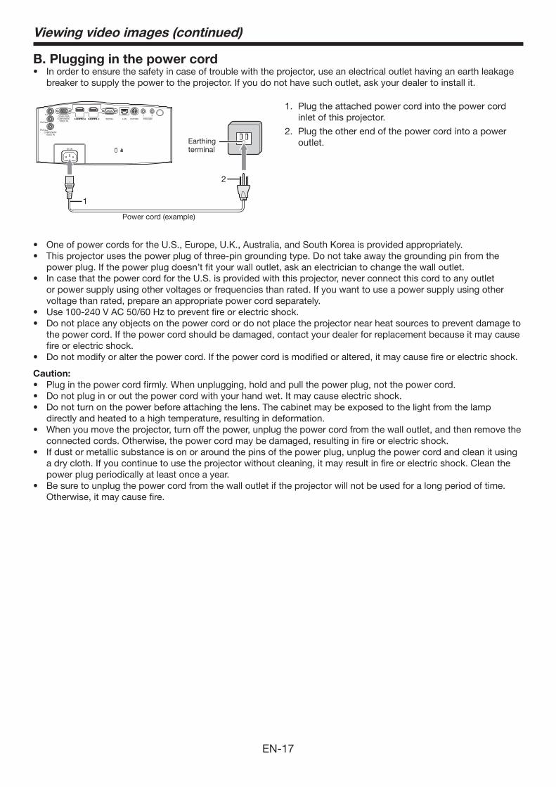
B. Plugging in the power cord
breaker to supply the power to the projector. If you do not have such outlet, ask your dealer to install it.
power plug. If the power plug doesn’t fit your wall outlet, ask an electrician to change the wall outlet.
or power supply using other voltages or frequencies than rated. If you want to use a power supply using other voltage than rated, prepare an appropriate power cord separately.
the power cord. If the power cord should be damaged, contact your dealer for replacement because it may cause fire or electric shock.
Caution:
directly and heated to a high temperature, resulting in deformation.
connected cords. Otherwise, the power cord may be damaged, resulting in fire or electric shock.
a dry cloth. If you continue to use the projector without cleaning, it may result in fire or electric shock. Clean the power plug periodically at least once a year.
Otherwise, it may cause fire.
1. Plug the attached power cord into the power cord inlet of this projector.
2. Plug the other end of the power cord into a power outlet.
1
2
Power cord (example)
Earthing terminal
Viewing video images (continued)
EN-18
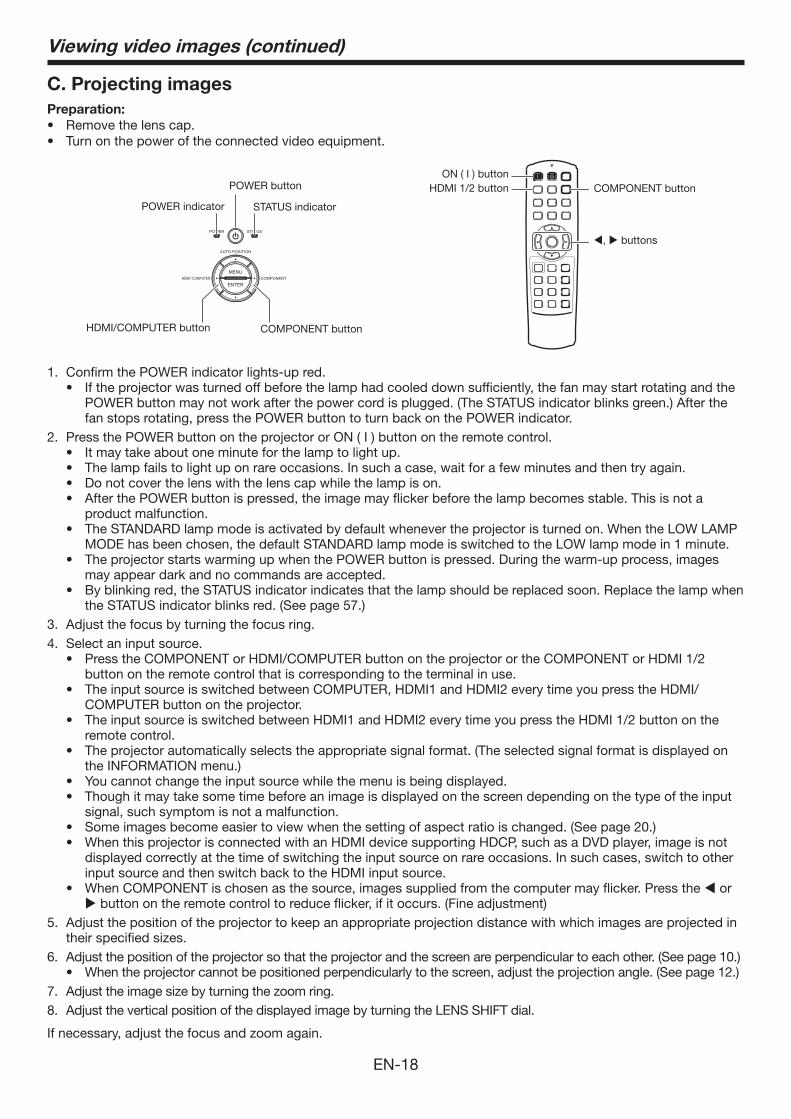
C. Projecting images
Preparation:
COMPONENT button
POWER button COMPONENT buttonON ( I ) button
HDMI 1/2 button
HDMI/COMPUTER button
STATUS indicatorPOWER indicator
, buttons
1. Confirm the POWER indicator lights-up red.
POWER button may not work after the power cord is plugged. (The STATUS indicator blinks green.) After the fan stops rotating, press the POWER button to turn back on the POWER indicator.
2. Press the POWER button on the projector or ON ( I ) button on the remote control.
product malfunction.
MODE has been chosen, the default STANDARD lamp mode is switched to the LOW lamp mode in 1 minute.
may appear dark and no commands are accepted.
the STATUS indicator blinks red. (See page 57.)3. Adjust the focus by turning the focus ring.4. Select an input source.
button on the remote control that is corresponding to the terminal in use.
COMPUTER button on the projector.
remote control.
the INFORMATION menu.)
signal, such symptom is not a malfunction.
displayed correctly at the time of switching the input source on rare occasions. In such cases, switch to other input source and then switch back to the HDMI input source.
or button on the remote control to reduce flicker, if it occurs. (Fine adjustment)
5. Adjust the position of the projector to keep an appropriate projection distance with which images are projected in their specified sizes.
6. Adjust the position of the projector so that the projector and the screen are perpendicular to each other. (See page 10.)When the projector cannot be positioned perpendicularly to the screen, adjust the projection angle. (See page 12.)
7. Adjust the image size by turning the zoom ring.8. Adjust the vertical position of the displayed image by turning the LENS SHIFT dial.
If necessary, adjust the focus and zoom again.
Viewing video images (continued)
EN-19
Viewing video images (continued)
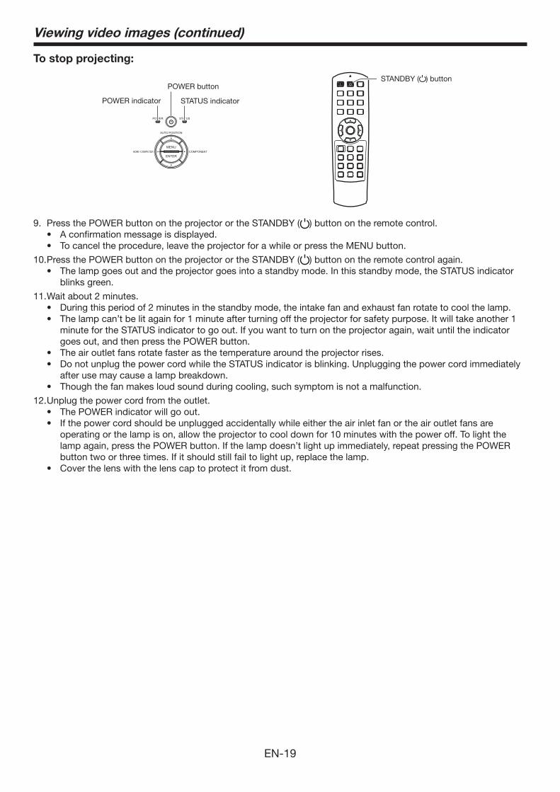
To stop projecting:
STANDBY ( ) buttonPOWER button
POWER indicator STATUS indicator
9. Press the POWER button on the projector or the STANDBY ( ) button on the remote control.
10. Press the POWER button on the projector or the STANDBY ( ) button on the remote control again.
blinks green.
11. Wait about 2 minutes.
minute for the STATUS indicator to go out. If you want to turn on the projector again, wait until the indicator goes out, and then press the POWER button.
after use may cause a lamp breakdown.
12. Unplug the power cord from the outlet.
operating or the lamp is on, allow the projector to cool down for 10 minutes with the power off. To light the lamp again, press the POWER button. If the lamp doesn’t light up immediately, repeat pressing the POWER button two or three times. If it should still fail to light up, replace the lamp.
EN-20
Viewing video images (continued)
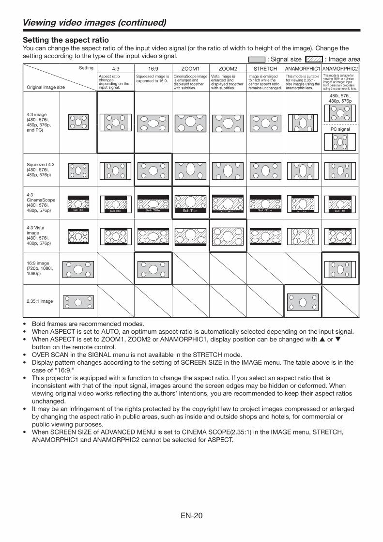
Setting the aspect ratioYou can change the aspect ratio of the input video signal (or the ratio of width to height of the image). Change the setting according to the type of the input video signal. : Signal size : Image area
Setting
Original image size
4:3 16:9 ZOOM1 ZOOM2 STRETCH ANAMORPHIC1 ANAMORPHIC2Aspect ratio changes depending on the input signal.
Squeezed image is expanded to 16:9.
CinemaScope image is enlarged and displayed together with subtitles.
Vista image is enlarged and displayed together with subtitles.
Image is enlarged to 16:9 while the center aspect ratio remains unchanged.
This mode is suitable for viewing 2.35:1-size images using the anamorphic lens.
This mode is suitable for viewing 16:9- or 4:3-size images or images input from personal computers using the anamorphic lens.
4:3 image (480i, 576i, 480p, 576p, and PC)
480i, 576i, 480p, 576p
PC signal
Squeezed 4:3(480i, 576i, 480p, 576p)
4:3 CinemaScope(480i, 576i, 480p, 576p) Sub Title Sub Title Sub Title Sub Title Sub Title
Sub TitleSub Title Sub Title
4:3 Vista image(480i, 576i, 480p, 576p)
16:9 image(720p, 1080i, 1080p)
2.35:1 image
or button on the remote control.
case of “16:9.”
inconsistent with that of the input signal, images around the screen edges may be hidden or deformed. When viewing original video works reflecting the authors’ intentions, you are recommended to keep their aspect ratios unchanged.
by changing the aspect ratio in public areas, such as inside and outside shops and hotels, for commercial or public viewing purposes.
ANAMORPHIC1 and ANAMORPHIC2 cannot be selected for ASPECT.
EN-21
How to change the settings:
With the remote control:
1. Press the ASPECT button or ANAMO button.
ZOOM2, to STRETCH, and back to AUTO.
and back to ANAMORPHIC1.
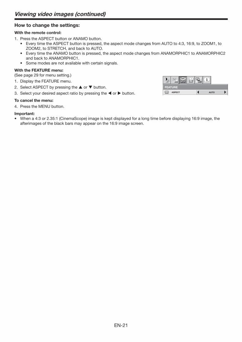
With the FEATURE menu:
(See page 29 for menu setting.)
1. Display the FEATURE menu.
2. Select ASPECT by pressing the or button.
3. Select your desired aspect ratio by pressing the or button.
To cancel the menu:
4. Press the MENU button.
Important:
afterimages of the black bars may appear on the 16:9 image screen.
AUTO
opt.
ASPECT
FEATURE
Viewing video images (continued)
EN-22
2
1
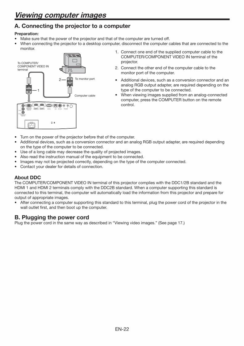
A. Connecting the projector to a computer
Preparation:
monitor. 1. Connect one end of the supplied computer cable to the
COMPUTER/COMPONENT VIDEO IN terminal of the projector.
2. Connect the other end of the computer cable to the monitor port of the computer.
analog RGB output adapter, are required depending on the type of the computer to be connected.
computer, press the COMPUTER button on the remote control.
on the type of the computer to be connected.
About DDCThe COMPUTER/COMPONENT VIDEO IN terminal of this projector complies with the DDC1/2B standard and the HDMI 1 and HDMI 2 terminals comply with the DDC2B standard. When a computer supporting this standard is connected to this terminal, the computer will automatically load the information from this projector and prepare for output of appropriate images.
wall outlet first, and then boot up the computer.
B. Plugging the power cordPlug the power cord in the same way as described in “Viewing video images.” (See page 17.)
To monitor port
To COMPUTER/COMPONENT VIDEO IN terminal
Computer cable
Viewing computer images
EN-23
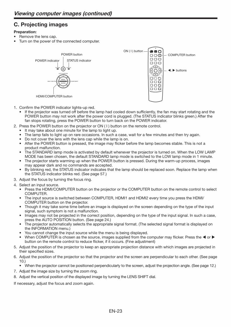
C. Projecting images
Preparation:
POWER buttonON ( I ) button
COMPUTER button
HDMI/COMPUTER button
POWER indicator STATUS indicator
, buttons
1. Confirm the POWER indicator lights-up red.
POWER button may not work after the power cord is plugged. (The STATUS indicator blinks green.) After the fan stops rotating, press the POWER button to turn back on the POWER indicator.
2. Press the POWER button on the projector or ON ( I ) button on the remote control.
product malfunction.
MODE has been chosen, the default STANDARD lamp mode is switched to the LOW lamp mode in 1 minute.
may appear dark and no commands are accepted.
the STATUS indicator blinks red. (See page 57.)3. Adjust the focus by turning the focus ring.4. Select an input source.
COMPUTER.
COMPUTER button on the projector.
signal, such symptom is not a malfunction.
press the AUTO POSITION button. (See page 24.)
the INFORMATION menu.)
or button on the remote control to reduce flicker, if it occurs. (Fine adjustment)
5. Adjust the position of the projector to keep an appropriate projection distance with which images are projected in their specified sizes.
6. Adjust the position of the projector so that the projector and the screen are perpendicular to each other. (See page 10.)
When the projector cannot be positioned perpendicularly to the screen, adjust the projection angle. (See page 12.)7. Adjust the image size by turning the zoom ring.8. Adjust the vertical position of the displayed image by turning the LENS SHIFT dial.
If necessary, adjust the focus and zoom again.
Viewing computer images (continued)
EN-24
Viewing computer images (continued)
To stop projecting:
9. Press the POWER button on the projector or the STANDBY ( ) button on the remote control.
10. Press the POWER button on the projector or the STANDBY ( ) button on the remote control again.
blinks green.
11. Wait about 2 minutes.
minute for the STATUS indicator to go out. If you want to turn on the projector again, wait until the indicator goes out, and then press the POWER button.
after use may cause a lamp breakdown.
12. Unplug the power cord from the outlet.
operating or the lamp is on, allow the projector to cool down for 10 minutes with the power off. To light the lamp again, press the POWER button. If the lamp doesn’t light up immediately, repeat pressing the POWER button two or three times. If it should still fail to light up, replace the lamp.
AUTO POSITION buttonWhen the image supplied from the computer is displaced, carry out the following procedure.
1. Display a bright image (such as a full-screen display of the Recycle Bin window).
2. When the screen saver has been enabled, disable it.
3. Press the AUTO POSITION button.The projector automatically makes optimum positional settings for the input signal.
times, change the settings in the SIGNAL menu to put the image in the correct position. (See page 34.)
When connecting to a notebook computer:When the projector is connected to a notebook computer, images may not be projected in some cases. In such cases, set the computer so that it can output signals externally. The setting procedure varies depending on the type of the computer. See the instruction manual of your computer.
Example of the setting procedure for external output
Press the [Fn] key and any of the keys [F1] to [F12] at the same time. (The key to be pressed depends on the type of the computer you use.)
Setting of the resolutionIf the resolution of the computer doesn’t match with that of the projector, projected images may be obscured. Ensure that their resolutions are the same (see page 59). For the method to change the output resolution of the computer, contact the manufacturer of the computer.
EN-25
Viewing 3D images
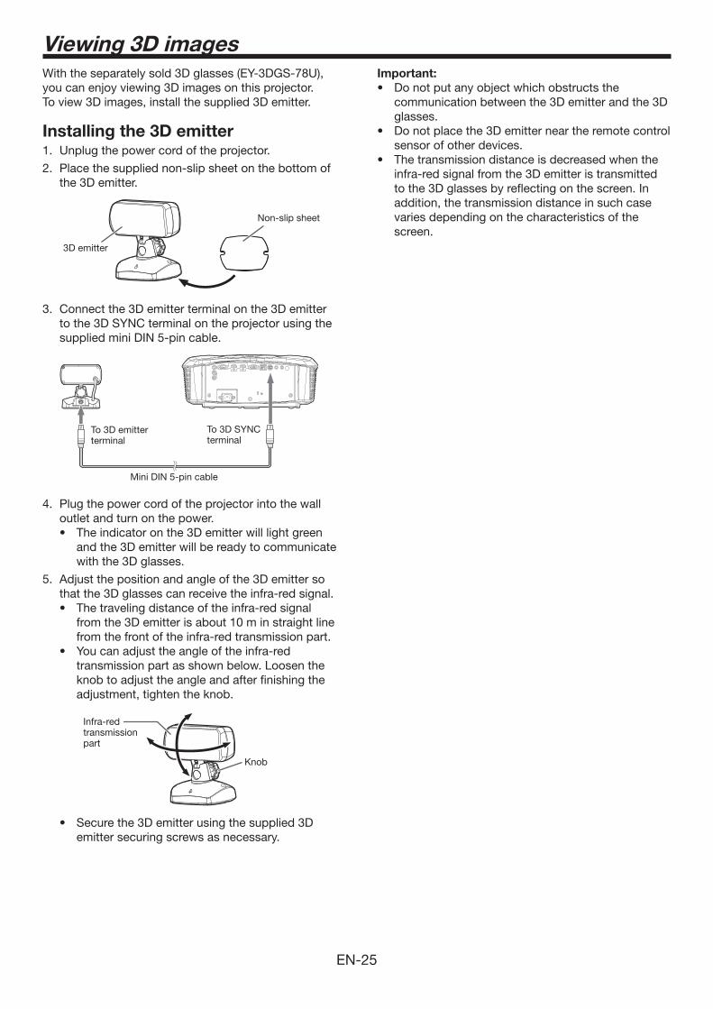
With the separately sold 3D glasses (EY-3DGS-78U), you can enjoy viewing 3D images on this projector. To view 3D images, install the supplied 3D emitter.
Installing the 3D emitter1. Unplug the power cord of the projector.
2. Place the supplied non-slip sheet on the bottom of the 3D emitter.
Non-slip sheet
3D emitter
3. Connect the 3D emitter terminal on the 3D emitter to the 3D SYNC terminal on the projector using the supplied mini DIN 5-pin cable.
To 3D SYNCterminal
To 3D emitterterminal
Mini DIN 5-pin cable
4. Plug the power cord of the projector into the wall outlet and turn on the power.
and the 3D emitter will be ready to communicate with the 3D glasses.
5. Adjust the position and angle of the 3D emitter so that the 3D glasses can receive the infra-red signal.
from the 3D emitter is about 10 m in straight line from the front of the infra-red transmission part.
transmission part as shown below. Loosen the knob to adjust the angle and after finishing the adjustment, tighten the knob.
Knob
Infra-red transmission part
emitter securing screws as necessary.
Important:
communication between the 3D emitter and the 3D glasses.
sensor of other devices.
infra-red signal from the 3D emitter is transmitted to the 3D glasses by reflecting on the screen. In addition, the transmission distance in such case varies depending on the characteristics of the screen.

EN-26
Viewing 3D images (continued)
3D images viewingThis projector is able to display the following 3D display supporting broadcasts and signals as stereoscopic images. (As of January, 2011)
supporting 3D display. (Side by side, top and bottom, and frame packing)
and BS digital broadcasting. (Side by side) (For viewing 3D images with CATV (cable television), please consult CATV broadcasters or CATV providers.)
(For details about the supported 3D image signal formats, see “3D supported signals” on page 59.)
This projector is also able to display 3D images converted from 2D images.
To view 3D images:
Preparation:
before viewing the 3D images.
of the recorder/player may be required when projecting 3D images from the recorder/player supporting 3D display. Read the user manual of the recorder/player for details.
1. Project a 3D image on the screen.
2. Display the IMAGE menu.
(See page 29 for menu setting.)3. Select 3D by pressing the or button.
OFF3D
4. Set 3D to ON by pressing the or button.
images.
5. Turn the power switch on the 3D glasses to ON.
6. Wear the 3D glasses.
To change the 3D viewing mode:
When 3D images aren’t displayed properly, change the following setting using the menu.(See page 29 for menu setting.)
1. Display the IMAGE menu and set the 3D option to ON .
2. Press the ENTER button.
3D
ON
NORMAL3D SYNC.
2D-3DCONVERSION
53D DEPTH
3D MODE AUTO
3. Press the or button to select the desired item and press the or button to select the desired option.
3D MODE
If 3D images aren’t displayed properly with AUTO selected, select the video format (FRAME PACKING, SIDE BY SIDE, or TOP AND BOTTOM) suitable for the 3D image being displayed. Alternatively, you can select the video format using the 3D MODE button on the remote control.
3D SYNC.
If you feel uncomfortable while viewing 3D images, the right-left synchronization between the 3D image and the 3D glasses (LCD shutter) may be lost. In such a case, set 3D SYNC. to REVERSE.
To convert 2D images to 3D images:
1. Project a 2D image.
2. Perform steps 2 to 4 in the section “To view 3D images.”
3. Press the ENTER button.
4. Select 3D MODE by pressing the or button.
3D MODE AUTO
5. Set 3D MODE to AUTO by pressing the or button.
6. Select 2D-3D CONVERSION by pressing the or button.
ON2D-3DCONVERSION
7. Set 2D-3D CONVERSION to ON by pressing the or button.
8. Turn the power switch on the 3D glasses to ON and wear the 3D glasses.
9. Select 3D DEPTH by pressing the or button.
53D DEPTH
10. Adjust the depth of the converted 3D images by pressing the or button.
10). As the level increases, the appearance of depth is enhanced.
blurred due to conversion.
3D CONVERSION back to OFF.
EN-27
Viewing 3D images (continued)
Important:
recommended distance, it will cause physical discomfort and eye fatigue.
used too far from the screen.
angle. If you are viewing the screen at big angle, you may not be able to view 3D contents correctly.
images. For persons with myopia, hypermetropia, astigmatism or left and right sights, please wear glasses to correct them then wear the 3D glasses.
projecting the 3D images, however, this is not a malfunction.
images are not displayed properly.While side-by-side or top-and-bottom 3D images are displayed, the aspect ratio setting is fixed to 16:9.
side-by-side or top-and-bottom 3D images, they are displayed in the 2D mode temporarily. When the menu or dialog disappears, they are displayed in the 3D mode again.
default setting) while you are watching the 3D images. The setting can not be changed.
as BD player through a HDMI signal distributor or AV amplifier via HDMI cable, make sure to use the HDMI signal distributor or AV amplifier supporting HDMI 1.4 (3D).
the 3D glasses lenses (liquid crystal shutter) by using the infra-red signals received from the 3D emitter. Therefore, in rare cases, a remote control of other devices such as an air conditioner or lighting apparatus which uses the infra-red signals may not operate properly (while you are watching the 3D images). However, it is not a malfunction.
Caution:
Notes on danger to public health during watching
3D image
tired, discomfort, or any other abnormality. It may cause you to feel unwell if continuing to watch the 3D image in such cases. Please take the necessary rest, do not continue watch the 3D image for a long time. Stop using the 3D glasses if you can clearly see double images when viewing 3D content. Prolonged use may cause eyesight fatigue.
with 2D image.
break after watching a movie. When watching 3D content on interactive devices such as 3D games or computers, take an appropriate break every 30-60 minutes. Prolonged use may cause eyesight fatigue.
3D images and playing 3D games until you are restored. If necessary, consult a doctor. Also, stop driving a car until you are restored (for about 2 hours). The period to restore varies with the individual.
children younger than 5 - 6 years old. As it is difficult to judge younger children’s reactions to fatigue or discomfort, their physical condition may deteriorate suddenly. When this product is being used by a child, the parent or guardian should check to ensure that the child’s eyes are not becoming tired.
shake or many dynamic pictures, if you feel uncomfortable, please look at another place.
rotation, or horizontal or vertical oscillation, you may feel as if you are actually moving. If such a feeling results in discomfort, look away from the screen.
the screen or other people by mistake. As the images are in 3D, you may mistake the distance from the screen, causing to strike the screen which may result in injury. When using the 3D glasses, do not place breakable objects near the glasses. You may move by mistaking the 3D objects you are viewing as the real objects, causing damages to surrounding objects that may lead to injury.
are on an approximate horizontal level. If you suffer from myopia (short sightedness), hyperopia (far-sightedness), astigmatism, or have eyesight differences between the left and right eyes, please use corrective glasses or other such methods to correct your eyesight before putting on the 3D glasses.
from the screen of about three times the effective height of the screen.
EN-28
Menu operation
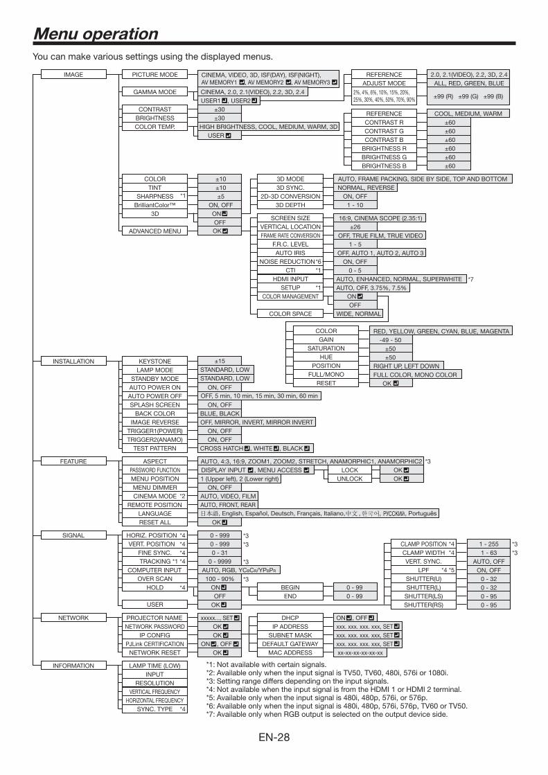
You can make various settings using the displayed menus.
INSTALLATION
OFF, MIRROR, INVERT, MIRROR INVERT
AUTO POWER ON ON, OFF
RESET ALL OK
AUTO POWER OFFON, OFF
ON, OFF
FEATURE
MENU POSITION 1 (Upper left), 2 (Lower right)MENU DIMMER ON, OFF
IMAGE REVERSE
SPLASH SCREENBLUE, BLACKBACK COLOR
STANDARD, LOW5
LAMP MODESTANDARD, LOWSTANDBY MODE
KEYSTONE
AUTO, 4:3, 16:9, ZOOM1, ZOOM2, STRETCH, ANAMORPHIC1, ANAMORPHIC2ASPECTDISPLAY INPUT , MENU ACCESS PASSWORD FUNCTION
LANGUAGE , English, Español, Deutsch, Français, Italiano, , , , Português
SIGNAL
INFORMATION
HORIZ. POSITION
HOLD
REMOTE POSITION
0 - 999VERT. POSITION 0 - 999
FINE SYNC. 0 - 31TRACKING
USER
0 - 9999
CLAMP POSITION 1 - 255CLAMP WIDTH 1 - 63
LPF ON, OFFOVER SCAN
SHUTTER(L) 0 - 32SHUTTER(U) 0 - 32
SHUTTER(RS) 0 - 95SHUTTER(LS) 0 - 95
VERT. SYNC. AUTO, OFF
*3
*3
*3*3
*1 *4
*4
NETWORK PROJECTOR NAME xxxxx..., SET
*4*4
*4
*4
AUTO, VIDEO, FILMCINEMA MODE
*4*4
*4 *5
*3
*3
*3
OFFBEGIN 0 - 99END 0 - 99
DHCPIP ADDRESS xxx. xxx. xxx. xxx, SET
COMPUTER INPUT
SYNC. TYPE
LAMP TIME (LOW)INPUT
RESOLUTION
HORIZONTAL FREQUENCYVERTICAL FREQUENCY
AUTO, RGB, YCBCR/YPBPR
AUTO, FRONT, REAR
OFF, 5 min, 10 min, 15 min, 30 min, 60 min
OK
OK
ON
UNLOCK OK LOCK
*2
IMAGE
GAMMA MODEUSER1 , USER2
PICTURE MODE CINEMA, VIDEO, 3D, ISF(DAY), ISF(NIGHT),AV MEMORY1 , AV MEMORY2 , AV MEMORY3
COLORTINT
SHARPNESS
)
REFERENCE 2.0, 2.1(VIDEO), 2.2, 3D, 2.4ADJUST MODE ALL, RED, GREEN, BLUE
NOISE REDUCTIONCTI
SETUP
CINEMA, 2.0, 2.1(VIDEO), 2.2, 3D, 2.4
*1
BrilliantColor™ ON, OFF3D ON
OFF
*6*1
*1
ADVANCED MENU OK
AUTO, FRAME PACKING, SIDE BY SIDE, TOP AND BOTTOM3D MODE3D SYNC.
2D-3D CONVERSION3D DEPTH
NORMAL, REVERSEON, OFF
1 - 10
SCREEN SIZE 16:9, CINEMA SCOPE (2.35:1)VERTICAL LOCATION 6FRAME RATE CONVERSION OFF, TRUE FILM, TRUE VIDEO
F.R.C. LEVEL 1 - 5AUTO IRIS OFF, AUTO 1, AUTO 2, AUTO 3
ON, OFF0 - 5
COLOR RED, YELLOW, GREEN, CYAN, BLUE, MAGENTAGAIN -49 - 50
SATURATION 0HUE 0
POSITION RIGHT UP, LEFT DOWNFULL/MONO FULL COLOR, MONO COLOR
RESET OK
AUTO, OFF*7HDMI INPUT AUTO, ENHANCED, NORMAL, SUPERWHITE
COLOR MANAGEMENT
TRIGGER1(POWER)ON, OFFTRIGGER2(ANAMO)
CROSS HATCH , WHITE , BLACK TEST PATTERN
CONTRASTBRIGHTNESS
HIGH BRIGHTNESS, COOL, MEDIUM, WARM, 3DUSER
CONTRAST BBRIGHTNESS RBRIGHTNESS GBRIGHTNESS B
CONTRAST R 000000
REFERENCE COOL, MEDIUM, WARM
CONTRAST GCOLOR TEMP.
ON
COLOR SPACE WIDE, NORMALOFF
NETWORK PASSWORD OK IP CONFIG OK
PJLink CERTIFICATION ON , OFF
ON , OFF
NETWORK RESET OK
xxx. xxx. xxx. xxx, SET xxx. xxx. xxx. xxx, SET
SUBNET MASKDEFAULT GATEWAY
MAC ADDRESS xx-xx-xx-xx-xx-xx
*1: Not available with certain signals.*2: Available only when the input signal is TV50, TV60, 480i, 576i or 1080i.*3: Setting range differs depending on the input signals.*4: Not available when the input signal is from the HDMI 1 or HDMI 2 terminal.*5: Available only when the input signal is 480i, 480p, 576i, or 576p.*6: Available only when the input signal is 480i, 480p, 576i, 576p, TV60 or TV50. *7: Available only when RGB output is selected on the output device side.
EN-29
Menu operation (continued)
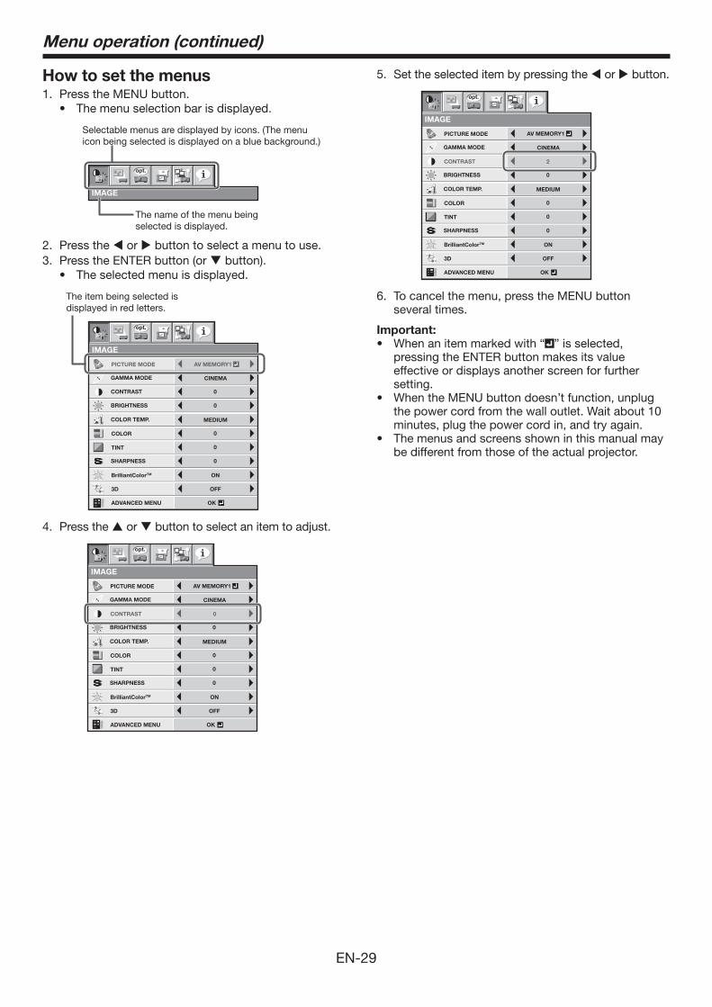
How to set the menus1. Press the MENU button.
IMAGE
opt.
Selectable menus are displayed by icons. (The menu icon being selected is displayed on a blue background.)
The name of the menu being selected is displayed.
2. Press the or button to select a menu to use.3. Press the ENTER button (or button).
CONTRAST
IMAGE
0
BRIGHTNESS 0
0
COLOR
OK
MEDIUM
0
TINT
0SHARPNESS
ONBrilliantColorTM
OFF3D
COLOR TEMP.
ADVANCED MENU
opt.
CINEMAGAMMA MODE
AV MEMORY1PICTURE MODE
The item being selected is displayed in red letters.
4. Press the or button to select an item to adjust.
CONTRAST
IMAGE
0
BRIGHTNESS 0
0
COLOR
OK
MEDIUM
0
TINT
0SHARPNESS
ONBrilliantColorTM
OFF3D
COLOR TEMP.
ADVANCED MENU
opt.
CINEMAGAMMA MODE
PICTURE MODE AV MEMORY1
5. Set the selected item by pressing the or button.
CONTRAST
IMAGE
2
BRIGHTNESS 0
0
COLOR
OK
MEDIUM
0
TINT
0SHARPNESS
ONBrilliantColorTM
OFF3D
COLOR TEMP.
ADVANCED MENU
opt.
CINEMAGAMMA MODE
PICTURE MODE AV MEMORY1
6. To cancel the menu, press the MENU button several times.
Important:
When an item marked with “ ” is selected, pressing the ENTER button makes its value effective or displays another screen for further setting.
When the MENU button doesn’t function, unplug the power cord from the wall outlet. Wait about 10 minutes, plug the power cord in, and try again.
The menus and screens shown in this manual may be different from those of the actual projector.
EN-30
Menu itemsSet the following items provided in the respective menus.
IMAGE menu
CONTRAST
IMAGE
0
BRIGHTNESS 0
0
COLOR
OK
MEDIUM
0
TINT
0SHARPNESS
ONBrilliantColorTM
OFF3D
COLOR TEMP.
ADVANCED MENU
opt.
CINEMAGAMMA MODE
AV MEMORY1PICTURE MODE
VERTICAL LOCATION
IMAGE
ADVANCED MENU
0
FRAME RATE CONVERSION TRUE FILM
OFF
AUTO IRIS
OFF
2
AUTO 1
NOISE REDUCTION
0CTI
AUTOHDMI INPUT
AUTOSETUP
F.R.C. LEVEL
COLOR MANAGEMENT
WIDECOLOR SPACE
opt.
16 : 9SCREEN SIZE
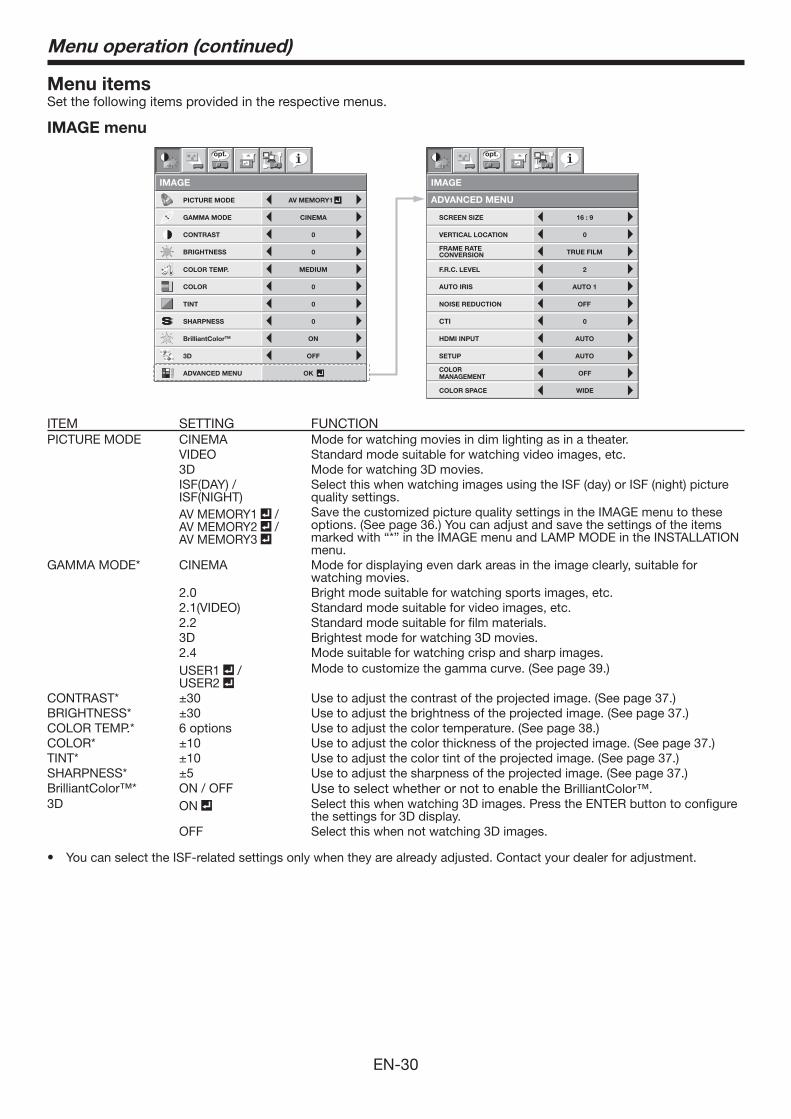
ITEM SETTING FUNCTIONPICTURE MODE CINEMA Mode for watching movies in dim lighting as in a theater.
VIDEO Standard mode suitable for watching video images, etc. 3D Mode for watching 3D movies. ISF(DAY) / ISF(NIGHT)
Select this when watching images using the ISF (day) or ISF (night) picture quality settings.
AV MEMORY1 / AV MEMORY2 /AV MEMORY3
Save the customized picture quality settings in the IMAGE menu to these options. (See page 36.) You can adjust and save the settings of the items marked with “*” in the IMAGE menu and LAMP MODE in the INSTALLATION menu.
GAMMA MODE* CINEMA Mode for displaying even dark areas in the image clearly, suitable for watching movies.
2.0 Bright mode suitable for watching sports images, etc. 2.1(VIDEO) Standard mode suitable for video images, etc. 2.2 Standard mode suitable for film materials. 3D Brightest mode for watching 3D movies. 2.4 Mode suitable for watching crisp and sharp images. USER1 / USER2
Mode to customize the gamma curve. (See page 39.)
CONTRAST* Use to adjust the contrast of the projected image. (See page 37.)BRIGHTNESS* Use to adjust the brightness of the projected image. (See page 37.)COLOR TEMP.* 6 options Use to adjust the color temperature. (See page 38.)COLOR* Use to adjust the color thickness of the projected image. (See page 37.)TINT* Use to adjust the color tint of the projected image. (See page 37.)SHARPNESS* Use to adjust the sharpness of the projected image. (See page 37.)BrilliantColor™* ON / OFF Use to select whether or not to enable the BrilliantColor™.3D ON Select this when watching 3D images. Press the ENTER button to configure
the settings for 3D display. OFF Select this when not watching 3D images.
You can select the ISF-related settings only when they are already adjusted. Contact your dealer for adjustment.
Menu operation (continued)
EN-31
IMAGE menu (continued)
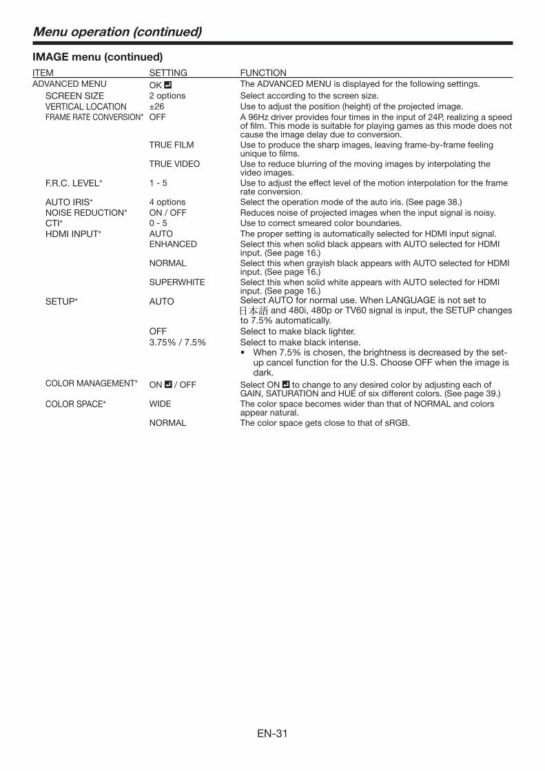
ITEM SETTING FUNCTIONADVANCED MENU OK The ADVANCED MENU is displayed for the following settings.
SCREEN SIZE 2 options Select according to the screen size.VERTICAL LOCATION Use to adjust the position (height) of the projected image.FRAME RATE CONVERSION* OFF A 96Hz driver provides four times in the input of 24P, realizing a speed
of film. This mode is suitable for playing games as this mode does not cause the image delay due to conversion.
TRUE FILM Use to produce the sharp images, leaving frame-by-frame feeling unique to films.
TRUE VIDEO Use to reduce blurring of the moving images by interpolating the video images.
F.R.C. LEVEL* 1 - 5 Use to adjust the effect level of the motion interpolation for the frame rate conversion.
AUTO IRIS* 4 options Select the operation mode of the auto iris. (See page 38.)NOISE REDUCTION* ON / OFF Reduces noise of projected images when the input signal is noisy.CTI* 0 - 5 Use to correct smeared color boundaries.HDMI INPUT* AUTO The proper setting is automatically selected for HDMI input signal.
ENHANCED Select this when solid black appears with AUTO selected for HDMI input. (See page 16.)
NORMAL Select this when grayish black appears with AUTO selected for HDMI input. (See page 16.)
SUPERWHITE Select this when solid white appears with AUTO selected for HDMI input. (See page 16.)
SETUP* AUTO Select AUTO for normal use. When LANGUAGE is not set to and 480i, 480p or TV60 signal is input, the SETUP changes
OFF Select to make black lighter.Select to make black intense.
up cancel function for the U.S. Choose OFF when the image is dark.
COLOR MANAGEMENT* ON / OFF Select ON to change to any desired color by adjusting each of GAIN, SATURATION and HUE of six different colors. (See page 39.)
COLOR SPACE* WIDE The color space becomes wider than that of NORMAL and colors appear natural.
NORMAL The color space gets close to that of sRGB.
Menu operation (continued)
EN-32
INSTALLATION menu
IMAGE
REVERSE
OFF
OFF
BACK COLOR
OFF
LOWLAMP MODE
STANDARDSTANDBY MODE
AUTO POWER
ON
AUTO POWER
OFF
INSTALLATION
TRIGGER1(POWER) OFF
TRIGGER2(ANAMO) OFF
ON ON
BLUE
SPLASH
SCREEN
TEST PATTERN CROSS HATCH
KEYSTONE 0
opt.
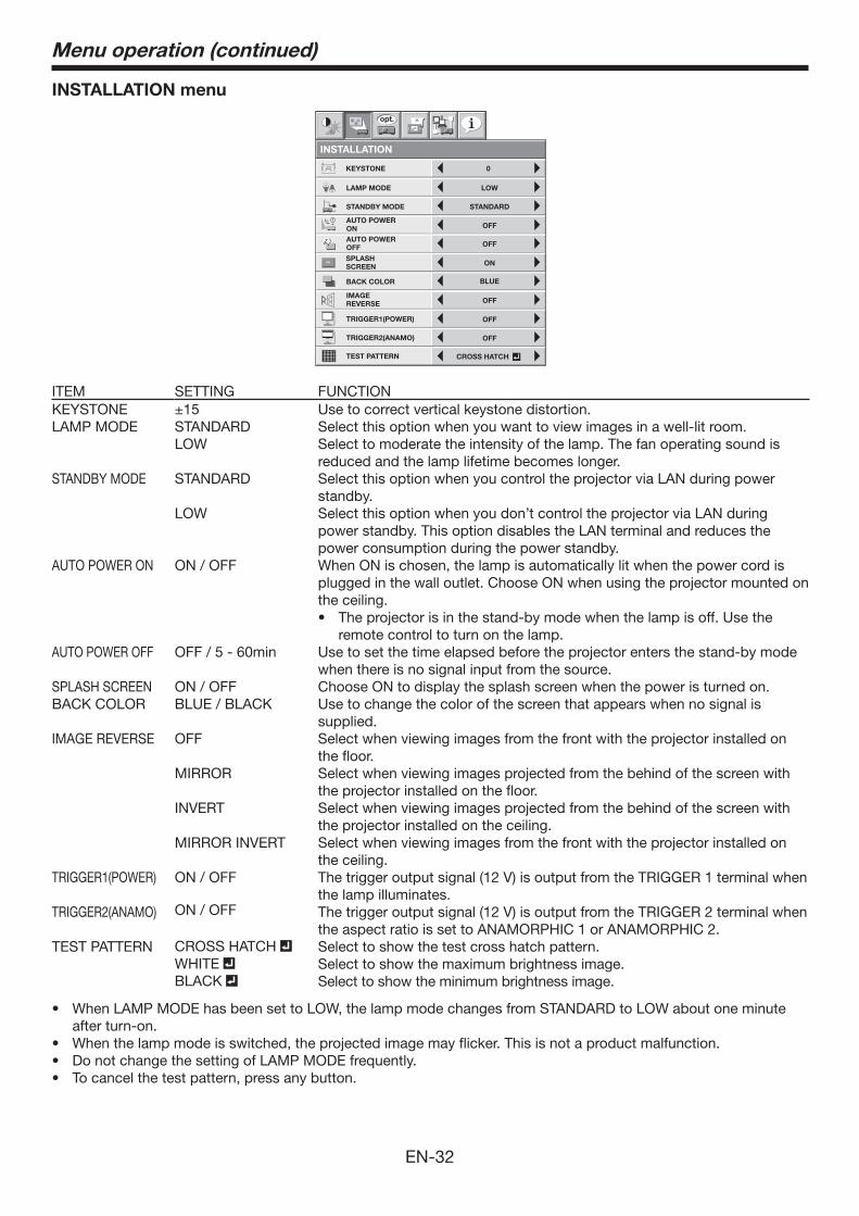
ITEM SETTING FUNCTIONKEYSTONE Use to correct vertical keystone distortion.LAMP MODE STANDARD Select this option when you want to view images in a well-lit room.
LOW Select to moderate the intensity of the lamp. The fan operating sound is reduced and the lamp lifetime becomes longer.
STANDBY MODE STANDARD Select this option when you control the projector via LAN during power standby.
LOW Select this option when you don’t control the projector via LAN during power standby. This option disables the LAN terminal and reduces the power consumption during the power standby.
AUTO POWER ON ON / OFF When ON is chosen, the lamp is automatically lit when the power cord is plugged in the wall outlet. Choose ON when using the projector mounted on the ceiling.
The projector is in the stand-by mode when the lamp is off. Use the remote control to turn on the lamp.
AUTO POWER OFF OFF / 5 - 60min Use to set the time elapsed before the projector enters the stand-by mode when there is no signal input from the source.
SPLASH SCREEN ON / OFF Choose ON to display the splash screen when the power is turned on.BACK COLOR BLUE / BLACK Use to change the color of the screen that appears when no signal is
supplied.IMAGE REVERSE OFF Select when viewing images from the front with the projector installed on
the floor.MIRROR Select when viewing images projected from the behind of the screen with
the projector installed on the floor.INVERT Select when viewing images projected from the behind of the screen with
the projector installed on the ceiling.MIRROR INVERT Select when viewing images from the front with the projector installed on
the ceiling.TRIGGER1(POWER) ON / OFF The trigger output signal (12 V) is output from the TRIGGER 1 terminal when
the lamp illuminates.TRIGGER2(ANAMO) ON / OFF The trigger output signal (12 V) is output from the TRIGGER 2 terminal when
the aspect ratio is set to ANAMORPHIC 1 or ANAMORPHIC 2.TEST PATTERN CROSS HATCH Select to show the test cross hatch pattern.
WHITE Select to show the maximum brightness image.BLACK Select to show the minimum brightness image.
after turn-on.
Menu operation (continued)
EN-33
FEATURE menu
AUTO
AUTO
AUTO
opt.
MENU POSITION
CINEMA MODE
REMOTE POSITION
ASPECT
RESET ALL
EnglishLANGUAGEA Ë
OK
DISPLAYINPUT
1.
MENU DIMMER OFF
FEATURE
PASSWORDFUNCTION
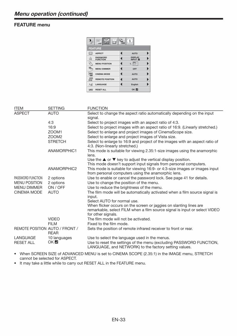
ITEM SETTING FUNCTIONASPECT AUTO Select to change the aspect ratio automatically depending on the input
signal.4:3 Select to project images with an aspect ratio of 4:3.16:9 Select to project images with an aspect ratio of 16:9. (Linearly stretched.)ZOOM1 Select to enlarge and project images of CinemaScope size.ZOOM2 Select to enlarge and project images of Vista size.STRETCH Select to enlarge to 16:9 and project of the images with an aspect ratio of
4:3. (Non-linearly stretched.)ANAMORPHIC1 This mode is suitable for viewing 2.35:1-size images using the anamorphic
lens. Use the or key to adjust the vertical display position. This mode doesn’t support input signals from personal computers.
ANAMORPHIC2 This mode is suitable for viewing 16:9- or 4:3-size images or images input from personal computers using the anamorphic lens.
PASSWORD FUNCTION 2 options Use to enable or cancel the password lock. See page 41 for details.MENU POSITION 2 options Use to change the position of the menu.MENU DIMMER ON / OFF Use to reduce the brightness of the menu.CINEMA MODE AUTO The film mode will be automatically activated when a film source signal is
input.Select AUTO for normal use. When flicker occurs on the screen or jaggies on slanting lines are remarkable, select FILM when a film source signal is input or select VIDEO for other signals.
VIDEO The film mode will not be activated.FILM Fixed to the film mode.
REMOTE POSITION AUTO / FRONT / REAR
Sets the position of remote infrared receiver to front or rear.
LANGUAGE 10 languages Use to select the language used in the menus.RESET ALL OK Use to reset the settings of the menu (excluding PASSWORD FUNCTION,
LANGUAGE, and NETWORK) to the factory setting values.
When SCREEN SIZE of ADVANCED MENU is set to CINEMA SCOPE (2.35:1) in the IMAGE menu, STRETCH cannot be selected for ASPECT.It may take a little while to carry out RESET ALL in the FEATURE menu.
Menu operation (continued)
EN-34
SIGNAL menu
R G BR G B
SIGNAL
HORIZ. POSITION 0
VERT. POSITION 0
TRACKING 0
COMPUTER INPUT
AUTO
FINE SYNC. 0
USER
opt.
OK
ONHOLD
100%OVER SCAN
SIGNAL
USER
CLAMP POSITION 1
1
AUTO
OFF
0
LPF
VERT. SYNC.
CLAMP WIDTH
opt.
SHUTTER(U)
SHUTTER(L)
SHUTTER(LS)
SHUTTER(RS)
0
0
0
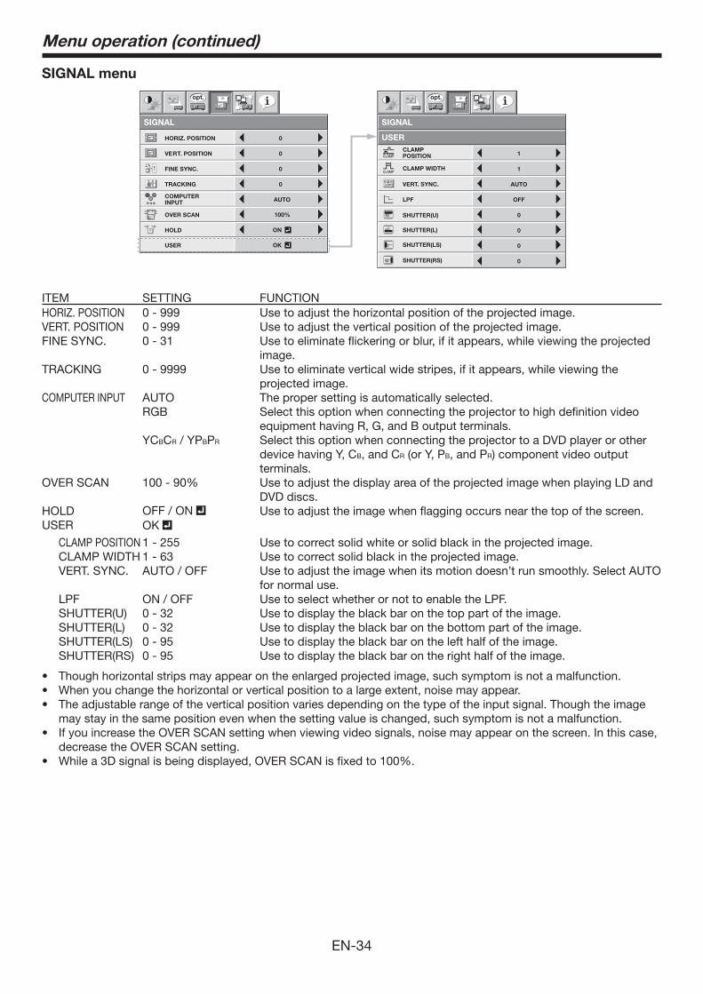
ITEM SETTING FUNCTIONHORIZ. POSITION 0 - 999 Use to adjust the horizontal position of the projected image.VERT. POSITION 0 - 999 Use to adjust the vertical position of the projected image.FINE SYNC. 0 - 31 Use to eliminate flickering or blur, if it appears, while viewing the projected
image. TRACKING 0 - 9999 Use to eliminate vertical wide stripes, if it appears, while viewing the
projected image.COMPUTER INPUT AUTO The proper setting is automatically selected.
RGB Select this option when connecting the projector to high definition video equipment having R, G, and B output terminals.
YCBCR / YPBPR Select this option when connecting the projector to a DVD player or other device having Y, CB, and CR (or Y, PB, and PR) component video output terminals.
OVER SCAN Use to adjust the display area of the projected image when playing LD and DVD discs.
HOLD OFF / ON Use to adjust the image when flagging occurs near the top of the screen.USER OK
CLAMP POSITION 1 - 255 Use to correct solid white or solid black in the projected image.CLAMP WIDTH 1 - 63 Use to correct solid black in the projected image.VERT. SYNC. AUTO / OFF Use to adjust the image when its motion doesn’t run smoothly. Select AUTO
for normal use.LPF ON / OFF Use to select whether or not to enable the LPF.SHUTTER(U) 0 - 32 Use to display the black bar on the top part of the image.SHUTTER(L) 0 - 32 Use to display the black bar on the bottom part of the image.SHUTTER(LS) 0 - 95 Use to display the black bar on the left half of the image.SHUTTER(RS) 0 - 95 Use to display the black bar on the right half of the image.
may stay in the same position even when the setting value is changed, such symptom is not a malfunction.
decrease the OVER SCAN setting.
Menu operation (continued)
EN-35
NETWORK menu
IP CONFIG
NETWORK
OK
PJLink CERTIFICATION
ON
NETWORK RESET OK
opt.
OKNETWORK PASSWORD
PROJECTOR NAME
IP ADDRESS
NETWORK
IP CONFIG
0. 0. 0. 0
SUBNET MASK 0. 0. 0. 0
MAC ADDRESS
0. 0. 0. 0
XX-XX-XX-XX-XX-XX
DEFAULT GATEWAY
opt.
DHCP ON
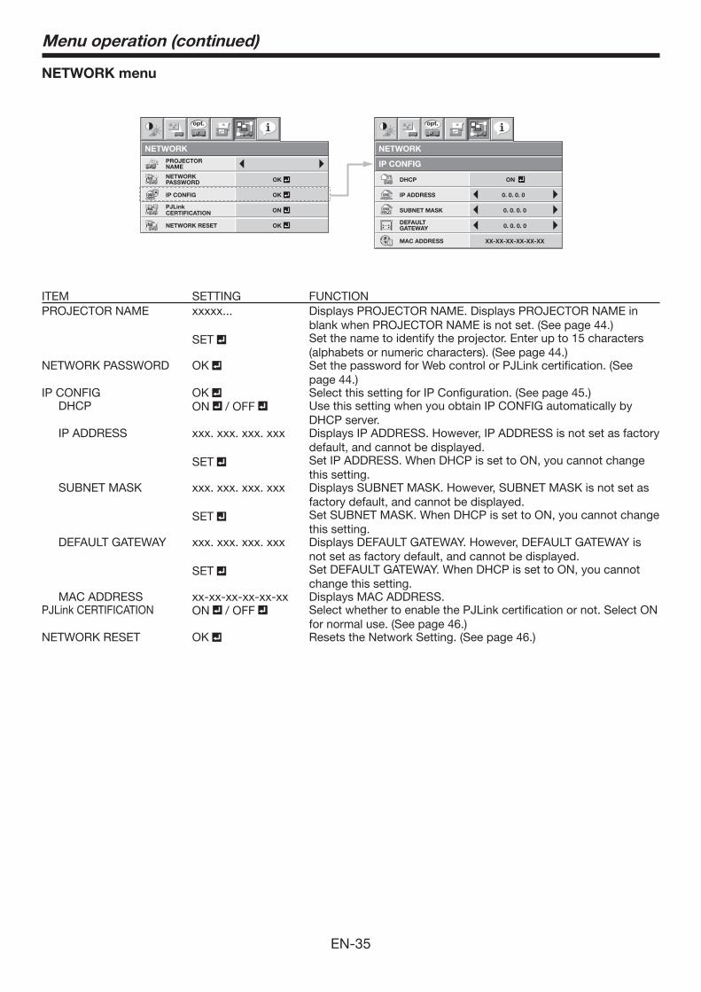
ITEM SETTING FUNCTIONPROJECTOR NAME xxxxx... Displays PROJECTOR NAME. Displays PROJECTOR NAME in
blank when PROJECTOR NAME is not set. (See page 44.)SET Set the name to identify the projector. Enter up to 15 characters
(alphabets or numeric characters). (See page 44.)NETWORK PASSWORD OK Set the password for Web control or PJLink certification. (See
page 44.)IP CONFIG OK Select this setting for IP Configuration. (See page 45.)
DHCP ON / OFF Use this setting when you obtain IP CONFIG automatically by DHCP server.
IP ADDRESS xxx. xxx. xxx. xxx Displays IP ADDRESS. However, IP ADDRESS is not set as factory default, and cannot be displayed.
SET Set IP ADDRESS. When DHCP is set to ON, you cannot changethis setting.
SUBNET MASK xxx. xxx. xxx. xxx Displays SUBNET MASK. However, SUBNET MASK is not set as factory default, and cannot be displayed.
SET Set SUBNET MASK. When DHCP is set to ON, you cannot change this setting.
DEFAULT GATEWAY xxx. xxx. xxx. xxx Displays DEFAULT GATEWAY. However, DEFAULT GATEWAY is not set as factory default, and cannot be displayed.
SET Set DEFAULT GATEWAY. When DHCP is set to ON, you cannot change this setting.
MAC ADDRESS xx-xx-xx-xx-xx-xx Displays MAC ADDRESS.PJLink CERTIFICATION ON / OFF Select whether to enable the PJLink certification or not. Select ON
for normal use. (See page 46.)NETWORK RESET OK Resets the Network Setting. (See page 46.)
Menu operation (continued)
EN-36
Menu operation (continued)
INFORMATION menu
INFORMATION
opt.
LAMP TIME(LOW)
INPUT
RESOLUTION
VERTICAL
FREQUENCY
HORIZONTAL
FREQUENCY
SYNC. TYPE 5wire
60.02 KHz
75.04 Hz
1024X768
COMPUTER
0 H
R G
H V
B
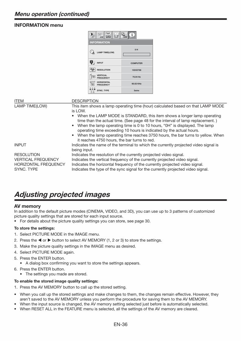
ITEM DESCRIPTIONLAMP TIME(LOW) This item shows a lamp operating time (hour) calculated based on that LAMP MODE
is LOW.
time than the actual time. (See page 48 for the interval of lamp replacement. )
operating time exceeding 10 hours is indicated by the actual hours.
it reaches 4750 hours, the bar turns to red.INPUT Indicates the name of the terminal to which the currently projected video signal is
being input.RESOLUTION Indicates the resolution of the currently projected video signal.VERTICAL FREQUENCY Indicates the vertical frequency of the currently projected video signal.HORIZONTAL FREQUENCY Indicates the horizontal frequency of the currently projected video signal.SYNC. TYPE Indicates the type of the sync signal for the currently projected video signal.
AV memoryIn addition to the default picture modes (CINEMA, VIDEO, and 3D), you can use up to 3 patterns of customized picture quality settings that are stored for each input source.
To store the settings:
1. Select PICTURE MODE in the IMAGE menu.
2. Press the or button to select AV MEMORY (1, 2 or 3) to store the settings.
3. Make the picture quality settings in the IMAGE menu as desired.
4. Select PICTURE MODE again.
5. Press the ENTER button.
6. Press the ENTER button.
To enable the stored image quality settings:
1. Press the AV MEMORY button to call up the stored setting.
aren’t saved to the AV MEMORY unless you perform the procedure for saving them to the AV MEMORY.
Adjusting projected images

EN-37
To adjust the brightness (CONTRAST and BRIGHTNESS):You can make adjustments for the brightness of the projected image using the menu.(See page 29 for menu setting.)
1. Display the IMAGE menu.
2. Select CONTRAST or BRIGHTNESS by pressing the or button.
3. Adjust the selected item by pressing the or button.
To cancel the menu:
4. Press the MENU button.
CONTRAST
Select to adjust the contrast of the image. Every time the button is pressed, the image becomes brighter and more defined. Every time the button is pressed, the image becomes darker and less defined.
BRIGHTNESS
Every time the button is pressed, the image becomes brighter. Every time the button is pressed, the image becomes darker.
To adjust the color (COLOR and TINT):You can adjust the color of the projected image using the menu.(See page 29 for menu setting.)
1. Display the IMAGE menu.
2. Select COLOR or TINT by pressing the or button.
3. Adjust the selected item by pressing the or button.
To cancel the menu:
4. Press the MENU button.
COLOR
Use to adjust the color intensity of the projected image. Every time the button is pressed, the color intensity increases. Every time the button is pressed, the color intensity decreases.
TINT
Use to adjust the tint of the projected image. Every time the button is pressed, the image appears more greenish. Every time the button is pressed, the image appears more reddish.
To sharpen or soften the projected image (SHARPNESS):You can adjust the sharpness of the projected image using the menu.(See page 29 for menu setting.)
1. Display the IMAGE menu.
2. Select SHARPNESS by pressing the or button.
3. Adjust the selected item by pressing the or button.
To cancel the menu:
4. Press the MENU button.
To use BrilliantColor™:You can enable or disable BrilliantColor™ using the menu.(See page 29 for menu setting.)
1. Display the IMAGE menu.
2. Select BrilliantColor™ by pressing the or button.
3. Select ON or OFF by pressing the or button.
To cancel the menu:
4. Press the MENU button.
ON
Even in a bright home theater environment, you can view crisp and sharp images. Select ON when you want to view bright images such as when viewing 3D images.
OFF
BrilliantColor™ is disabled and the middle tone is adjusted to natural brightness.
Adjusting projected images (continued)
EN-38
To adjust the tone of white (COLOR TEMP.):You can select a preset color temperature (white tone) using the menu.(See page 29 for menu setting.)1. Display the IMAGE menu.2. Select COLOR TEMP. by pressing the or button.3. Select your desired color temperature by pressing the or button.
The color temperature of each option is as follows: COOL: Approx. 9300K, MEDIUM: Approx. 6500K (D65), WARM: Approx. 5800K.
To cancel the menu:
4. Press the MENU button.
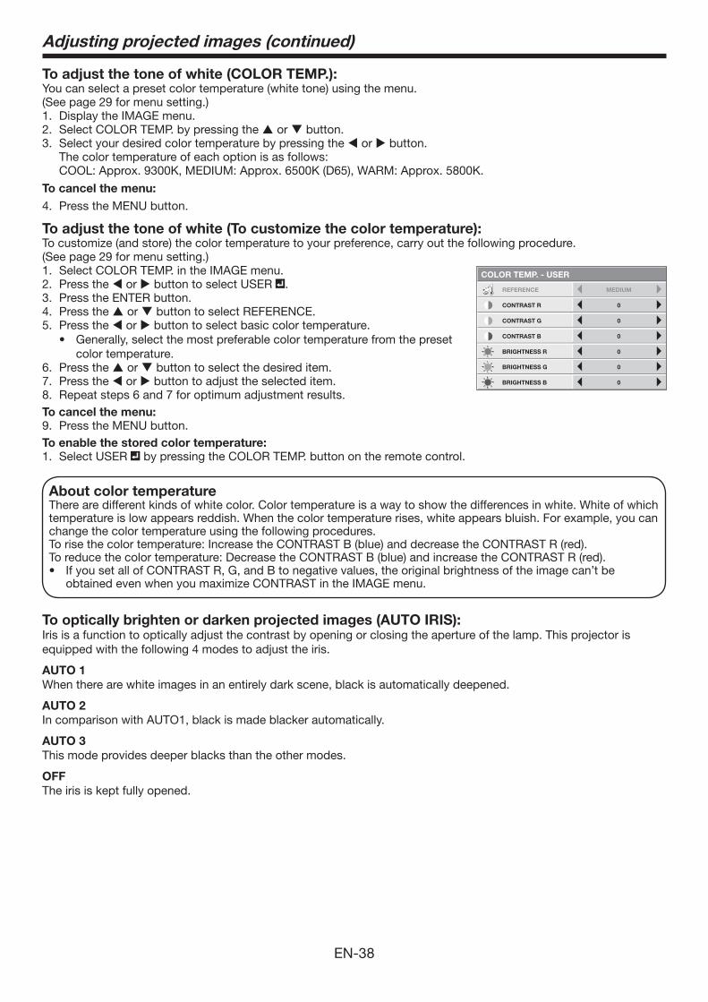
To adjust the tone of white (To customize the color temperature):To customize (and store) the color temperature to your preference, carry out the following procedure.(See page 29 for menu setting.)1. Select COLOR TEMP. in the IMAGE menu.2. Press the or button to select USER .3. Press the ENTER button.4. Press the or button to select REFERENCE.5. Press the or button to select basic color temperature.
color temperature from the preset color temperature.
6. Press the or button to select the desired item.7. Press the or button to adjust the selected item.8. Repeat steps 6 and 7 for optimum adjustment results.To cancel the menu:
9. Press the MENU button.To enable the stored color temperature:
1. Select USER by pressing the COLOR TEMP. button on the remote control.
Adjusting projected images (continued)
About color temperatureThere are different kinds of white color. Color temperature is a way to show the differences in white. White of which temperature is low appears reddish. When the color temperature rises, white appears bluish. For example, you can change the color temperature using the following procedures.To rise the color temperature: Increase the CONTRAST B (blue) and decrease the CONTRAST R (red).To reduce the color temperature: Decrease the CONTRAST B (blue) and increase the CONTRAST R (red).
obtained even when you maximize CONTRAST in the IMAGE menu.
CONTRAST R
COLOR TEMP. - USER
0
CONTRAST G 0
BRIGHTNESS G 0
BRIGHTNESS B 0
CONTRAST B 0
BRIGHTNESS R 0
REFERENCE MEDIUM
To optically brighten or darken projected images (AUTO IRIS): Iris is a function to optically adjust the contrast by opening or closing the aperture of the lamp. This projector is equipped with the following 4 modes to adjust the iris.
AUTO 1
When there are white images in an entirely dark scene, black is automatically deepened.
AUTO 2
In comparison with AUTO1, black is made blacker automatically.
AUTO 3
This mode provides deeper blacks than the other modes.
OFF
The iris is kept fully opened.
EN-39
Adjusting projected images (continued)
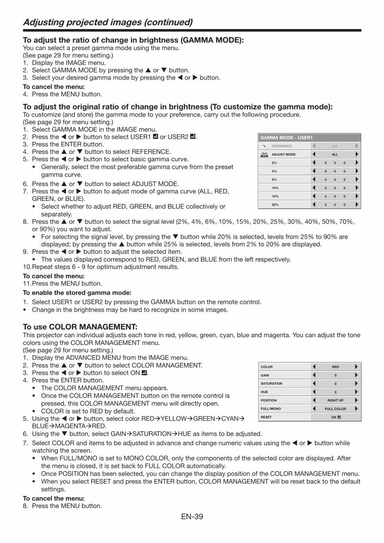
To adjust the ratio of change in brightness (GAMMA MODE):You can select a preset gamma mode using the menu.(See page 29 for menu setting.)1. Display the IMAGE menu.2. Select GAMMA MODE by pressing the or button.3. Select your desired gamma mode by pressing the or button.To cancel the menu:
4. Press the MENU button.
To adjust the original ratio of change in brightness (To customize the gamma mode):To customize (and store) the gamma mode to your preference, carry out the following procedure.(See page 29 for menu setting.)1. Select GAMMA MODE in the IMAGE menu.2. Press the or button to select USER1 or USER2 .3. Press the ENTER button.4. Press the or button to select REFERENCE.5. Press the or button to select basic gamma curve.
gamma curve.6. Press the or button to select ADJUST MODE.7. Press the or button to adjust mode of gamma curve (ALL, RED,
GREEN, or BLUE).
separately. 8. Press the or
For selecting the signal level, by pressing the
9. Press the or button to adjust the selected item.
10. Repeat steps 6 - 9 for optimum adjustment results.To cancel the menu:
11. Press the MENU button.To enable the stored gamma mode:
1. Select USER1 or USER2 by pressing the GAMMA button on the remote control.
To use COLOR MANAGEMENT:This projector can individual adjusts each tone in red, yellow, green, cyan, blue and magenta. You can adjust the tone colors using the COLOR MANAGEMENT menu.(See page 29 for menu setting.)1. Display the ADVANCED MENU from the IMAGE menu.2. Press the or button to select COLOR MANAGEMENT.3. Press the or button to select ON .4. Press the ENTER button.
pressed, this COLOR MANAGEMENT menu will directly open.
5. Using the or button, select color REDYELLOWGREENCYANBLUEMAGENTARED.
6. Using the button, select GAINSATURATIONHUE as items to be adjusted.7. Select COLOR and items to be adjusted in advance and change numeric values using the or button while
watching the screen.
the menu is closed, it is set back to FULL COLOR automatically.
settings. To cancel the menu:
8. Press the MENU button.
REFERENCE
GAMMA MODE - USER1
2.0
ALLADJUST MODE
0
0
0
0
0
0
0
0
0
0
0
0
0
0
0
0
0
0
2%
4%
6%
10%
15%
20%
COLOR
GAIN
SATURATION
HUE
POSITION
RED
0
0
0
RIGHT UP
FULL/MONO
RESET
FULL COLOR
OK
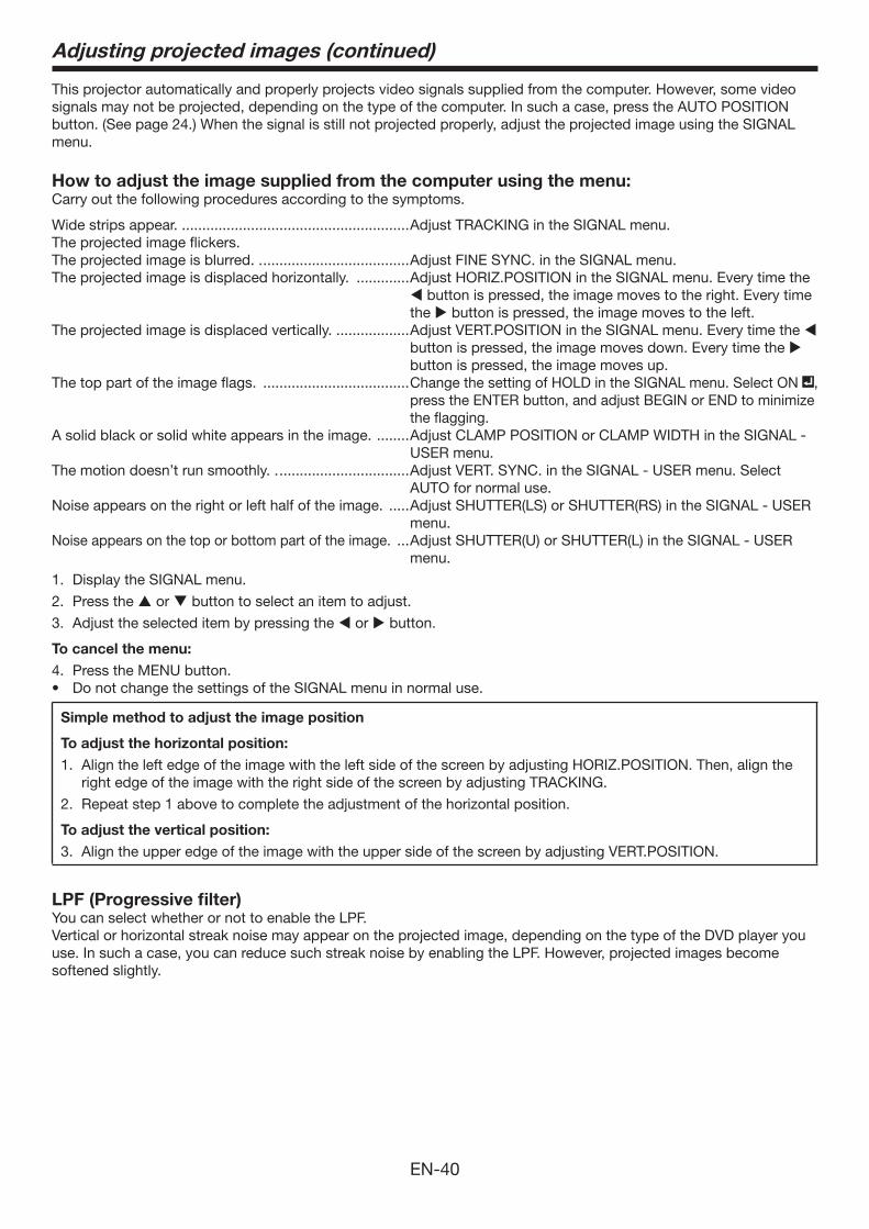
EN-40
This projector automatically and properly projects video signals supplied from the computer. However, some video signals may not be projected, depending on the type of the computer. In such a case, press the AUTO POSITION button. (See page 24.) When the signal is still not projected properly, adjust the projected image using the SIGNAL menu.
How to adjust the image supplied from the computer using the menu:Carry out the following procedures according to the symptoms.
Wide strips appear. . .......................................................Adjust TRACKING in the SIGNAL menu.The projected image flickers.The projected image is blurred. . ....................................Adjust FINE SYNC. in the SIGNAL menu.The projected image is displaced horizontally. .............Adjust HORIZ.POSITION in the SIGNAL menu. Every time the
button is pressed, the image moves to the right. Every time the button is pressed, the image moves to the left.
The projected image is displaced vertically. ..................Adjust VERT.POSITION in the SIGNAL menu. Every time the button is pressed, the image moves down. Every time the button is pressed, the image moves up.
The top part of the image flags. ....................................Change the setting of HOLD in the SIGNAL menu. Select ON , press the ENTER button, and adjust BEGIN or END to minimize the flagging.
A solid black or solid white appears in the image. ........Adjust CLAMP POSITION or CLAMP WIDTH in the SIGNAL - USER menu.
The motion doesn’t run smoothly. . ................................Adjust VERT. SYNC. in the SIGNAL - USER menu. Select AUTO for normal use.
Noise appears on the right or left half of the image. .....Adjust SHUTTER(LS) or SHUTTER(RS) in the SIGNAL - USER menu.
Noise appears on the top or bottom part of the image. ...Adjust SHUTTER(U) or SHUTTER(L) in the SIGNAL - USER menu.
1. Display the SIGNAL menu.
2. Press the or button to select an item to adjust.
3. Adjust the selected item by pressing the or button.
To cancel the menu:
4. Press the MENU button.
Simple method to adjust the image position
To adjust the horizontal position:
1. Align the left edge of the image with the left side of the screen by adjusting HORIZ.POSITION. Then, align the right edge of the image with the right side of the screen by adjusting TRACKING.
2. Repeat step 1 above to complete the adjustment of the horizontal position.
To adjust the vertical position:
3. Align the upper edge of the image with the upper side of the screen by adjusting VERT.POSITION.
LPF (Progressive filter)You can select whether or not to enable the LPF.Vertical or horizontal streak noise may appear on the projected image, depending on the type of the DVD player you use. In such a case, you can reduce such streak noise by enabling the LPF. However, projected images become softened slightly.
Adjusting projected images (continued)
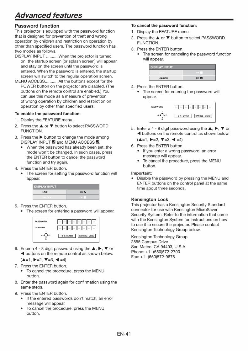
EN-41
Password functionThis projector is equipped with the password function that is designed for prevention of theft and wrong operation by children and restriction on operation by other than specified users. The password function has two modes as follows.DISPLAY INPUT .......... When the projector is turned
on, the startup screen (or splash screen) will appear and stay on the screen until the password is entered. When the password is entered, the startup screen will switch to the regular operation screen.
MENU ACCESS ........... All the buttons except for the POWER button on the projector are disabled. (The buttons on the remote control are enabled.) You can use this mode as a measure of prevention of wrong operation by children and restriction on operation by other than specified users.
To enable the password function:
1. Display the FEATURE menu.
2. Press the or button to select PASSWORD FUNCTION.
3. Press the button to change the mode among DISPLAY INPUT and MENU ACCESS .
mode won’t be changed. In such cases, press the ENTER button to cancel the password function and try again.
4. Press the ENTER button.
appear.
DISPLAY INPUT
LOCK
UNLOCK
OK
OK
5. Press the ENTER button.
PASSWORD
CONFIRM
1
3
24 O K : ENTER CANCEL : MENU
6. Enter a 4 - 8 digit password using the , , or buttons on the remote control as shown below.
(=1, =2, =3, =4)
7. Press the ENTER button.
button.
8. Enter the password again for confirmation using the same steps.
9. Press the ENTER button. ’t match, an error
message will appear.
button.
Advanced features
To cancel the password function:
1. Display the FEATURE menu.
2. Press the or button to select PASSWORD FUNCTION.
3. Press the ENTER button.
will appear.
DISPLAY INPUT
LOCK
UNLOCK
OK
OK
4. Press the ENTER button.
appear.
PASSWORD
1
3
24 O K : ENTER CANCEL : MENU
5. Enter a 4 - 8 digit password using the , , or buttons on the remote control as shown below.
(=1, =2, =3, =4)
6. Press the ENTER button.
message will appear.
button.
Important:
ENTER buttons on the control panel at the same time about three seconds.
Kensington LockThis projector has a Kensington Security Standard connector for use with Kensington MicroSaver Security System. Refer to the information that came with the Kensington System for instructions on how to use it to secure the projector. Please contact Kensington Technology Group below.
Kensington Technology Group2855 Campus DriveSan Mateo, CA 94403, U.S.A.
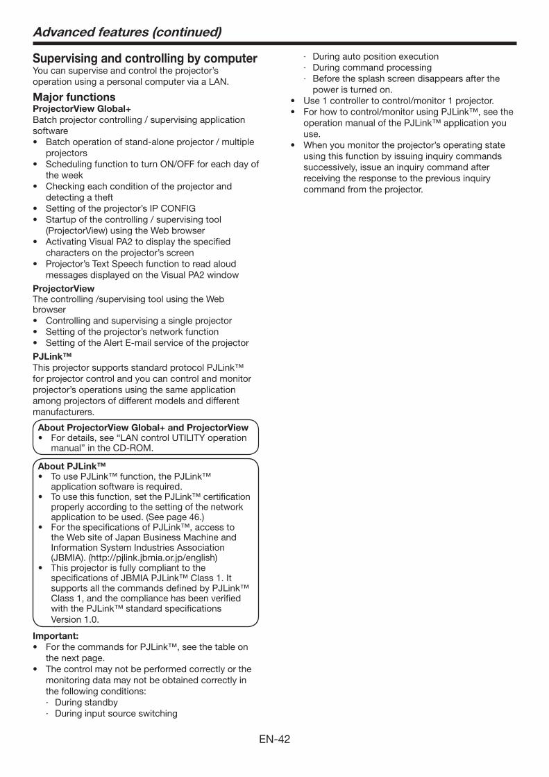
EN-42
Supervising and controlling by computerYou can supervise and control the projector’s operation using a personal computer via a LAN.
Major functionsProjectorView Global+
Batch projector controlling / supervising application software
projectors
the week
detecting a theft
(ProjectorView) using the Web browser
characters on the projector’s screen
messages displayed on the Visual PA2 window
ProjectorView
The controlling /supervising tool using the Web browser
PJLink™
This projector supports standard protocol PJLink™ for projector control and you can control and monitor projector’s operations using the same application among projectors of different models and different manufacturers.
About ProjectorView Global+ and ProjectorView
manual” in the CD-ROM.
About PJLink™
application software is required. To use this function, set the PJLink™ certification properly according to the setting of the network application to be used. (See page 46.)
the Web site of Japan Business Machine and Information System Industries Association (JBMIA). (http://pjlink.jbmia.or.jp/english)
specifications of JBMIA PJLink™ Class 1. It supports all the commands defined by PJLink™ Class 1, and the compliance has been verified with the PJLink™ standard specifications Version 1.0.
Important:
the next page.The control may not be performed correctly or the monitoring data may not be obtained correctly in the following conditions:· During standby· During input source switching
· During auto position execution· During command processing· Before the splash screen disappears after the
power is turned on.Use 1 controller to control/monitor 1 projector. For how to control/monitor using PJLink™, see the operation manual of the PJLink™ application you use.
using this function by issuing inquiry commands successively, issue an inquiry command after receiving the response to the previous inquiry command from the projector.
Advanced features (continued)
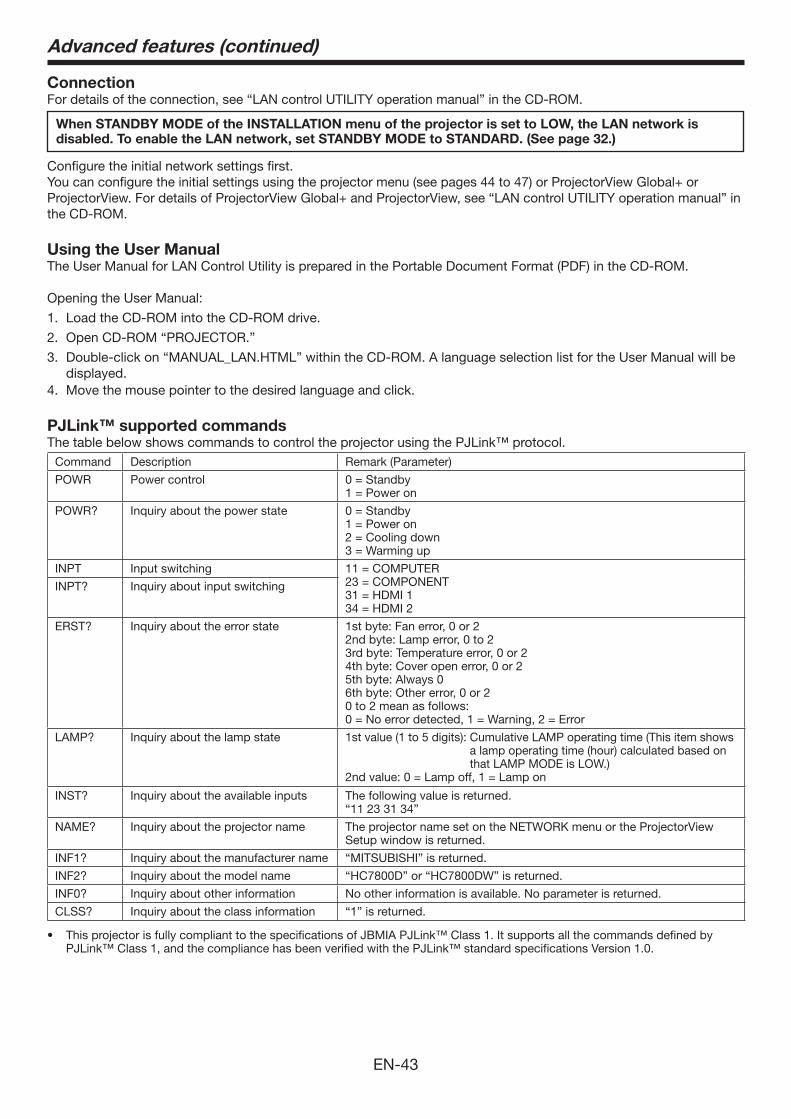
EN-43
ConnectionFor details of the connection, see “LAN control UTILITY operation manual” in the CD-ROM.
When STANDBY MODE of the INSTALLATION menu of the projector is set to LOW, the LAN network is
disabled. To enable the LAN network, set STANDBY MODE to STANDARD. (See page 32.)
Configure the initial network settings first.
the CD-ROM.
Using the User ManualThe User Manual for LAN Control Utility is prepared in the Portable Document Format (PDF) in the CD-ROM.
Opening the User Manual:
1. Load the CD-ROM into the CD-ROM drive.
2. Open CD-ROM “PROJECTOR.”
3. Double-click on “MANUAL_LAN.HTML” within the CD-ROM. A language selection list for the User Manual will be displayed.
4. Move the mouse pointer to the desired language and click.
PJLink™ supported commandsThe table below shows commands to control the projector using the PJLink™ protocol.
Command Description Remark (Parameter)
POWR Power control 0 = Standby1 = Power on
POWR? Inquiry about the power state 0 = Standby1 = Power on2 = Cooling down3 = Warming up
INPT Input switching 11 = COMPUTER23 = COMPONENT31 = HDMI 134 = HDMI 2
INPT? Inquiry about input switching
ERST? Inquiry about the error state 1st byte: Fan error, 0 or 22nd byte: Lamp error, 0 to 23rd byte: Temperature error, 0 or 24th byte: Cover open error, 0 or 25th byte: Always 06th byte: Other error, 0 or 20 to 2 mean as follows: 0 = No error detected, 1 = Warning, 2 = Error
LAMP? Inquiry about the lamp state 1st value (1 to 5 digits): Cumulative LAMP operating time (This item shows a lamp operating time (hour) calculated based on that LAMP MODE is LOW.)
2nd value: 0 = Lamp off, 1 = Lamp on
INST? Inquiry about the available inputs The following value is returned.“11 23 31 34”
NAME? Inquiry about the projector name The projector name set on the NETWORK menu or the ProjectorView Setup window is returned.
INF1? Inquiry about the manufacturer name “MITSUBISHI” is returned.
INF2? Inquiry about the model name “HC7800D” or “HC7800DW” is returned.
INF0? Inquiry about other information No other information is available. No parameter is returned.
CLSS? Inquiry about the class information “1” is returned.
This projector is fully compliant to the specifications of JBMIA PJLink™ Class 1. It supports all the commands defined by PJLink™ Class 1, and the compliance has been verified with the PJLink™ standard specifications Version 1.0.
Advanced features (continued)
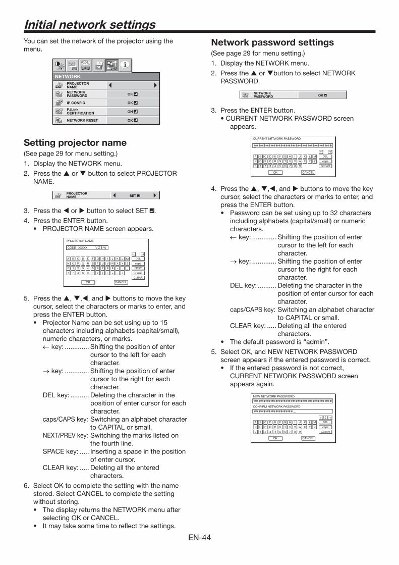
EN-44
Initial network settings
You can set the network of the projector using the menu.
IP CONFIG
NETWORK
OK
PJLink CERTIFICATION ON
NETWORK RESET OK
opt.
OKNETWORK PASSWORD
PROJECTOR NAME
Setting projector name(See page 29 for menu setting.)
1. Display the NETWORK menu.
2. Press the or button to select PROJECTOR NAME.
PROJECTOR NAME SET
3. Press the or button to select SET .
4. Press the ENTER button.
PROJECTOR NAME
CODE : XXXXX V Z $ %
A
OK
caps
NEXT
SPACE
CLEAR
DEL
CANCEL
B C D E F G H I J K L M
N O P Q R S T U V W X Y Z
0 1 2 3 4 5 6 7 8 9 – . _
! ” # $ % ’ ( ) * + , /
5. Press the , ,, and buttons to move the key cursor, select the characters or marks to enter, and press the ENTER button.
characters including alphabets (capital/small), numeric characters, or marks. key: ............. Shifting the position of enter
cursor to the left for each character.
key: ............. Shifting the position of enter cursor to the right for each character.
DEL key: .......... Deleting the character in the position of enter cursor for each character.
caps/CAPS key: Switching an alphabet character to CAPITAL or small.
NEXT/PREV key: Switching the marks listed on the fourth line.
SPACE key: ..... Inserting a space in the position of enter cursor.
CLEAR key: ..... Deleting all the entered characters.
6. Select OK to complete the setting with the name stored. Select CANCEL to complete the setting without storing.
selecting OK or CANCEL.
Network password settings(See page 29 for menu setting.)
1. Display the NETWORK menu.
2. Press the or button to select NETWORK PASSWORD.
NETWORK PASSWORD OK
3. Press the ENTER button.
appears.
CURRENT NETWORK PASSWORD
A
OK
caps
CLEAR
DEL
CANCEL
B C D E F G H I J K L M
N O P Q R S T U V W X Y Z
0 1 2 3 4 5 6 7 8 9
4. Press the , ,, and buttons to move the key cursor, select the characters or marks to enter, and press the ENTER button.
including alphabets (capital/small) or numeric characters. key: ............. Shifting the position of enter
cursor to the left for each character.
key: ............. Shifting the position of enter cursor to the right for each character.
DEL key: .......... Deleting the character in the position of enter cursor for each character.
caps/CAPS key: Switching an alphabet character to CAPITAL or small.
CLEAR key: ..... Deleting all the entered characters.
5. Select OK, and NEW NETWORK PASSWORD screen appears if the entered password is correct.
CURRENT NETWORK PASSWORD screen appears again.
CONFIRM NETWORK PASSWORD
A
OK
caps
CLEAR
DEL
CANCEL
B C D E F G H I J K L M
N O P Q R S T U V W X Y Z
0 1 2 3 4 5 6 7 8 9
NEW NETWORK PASSWORD
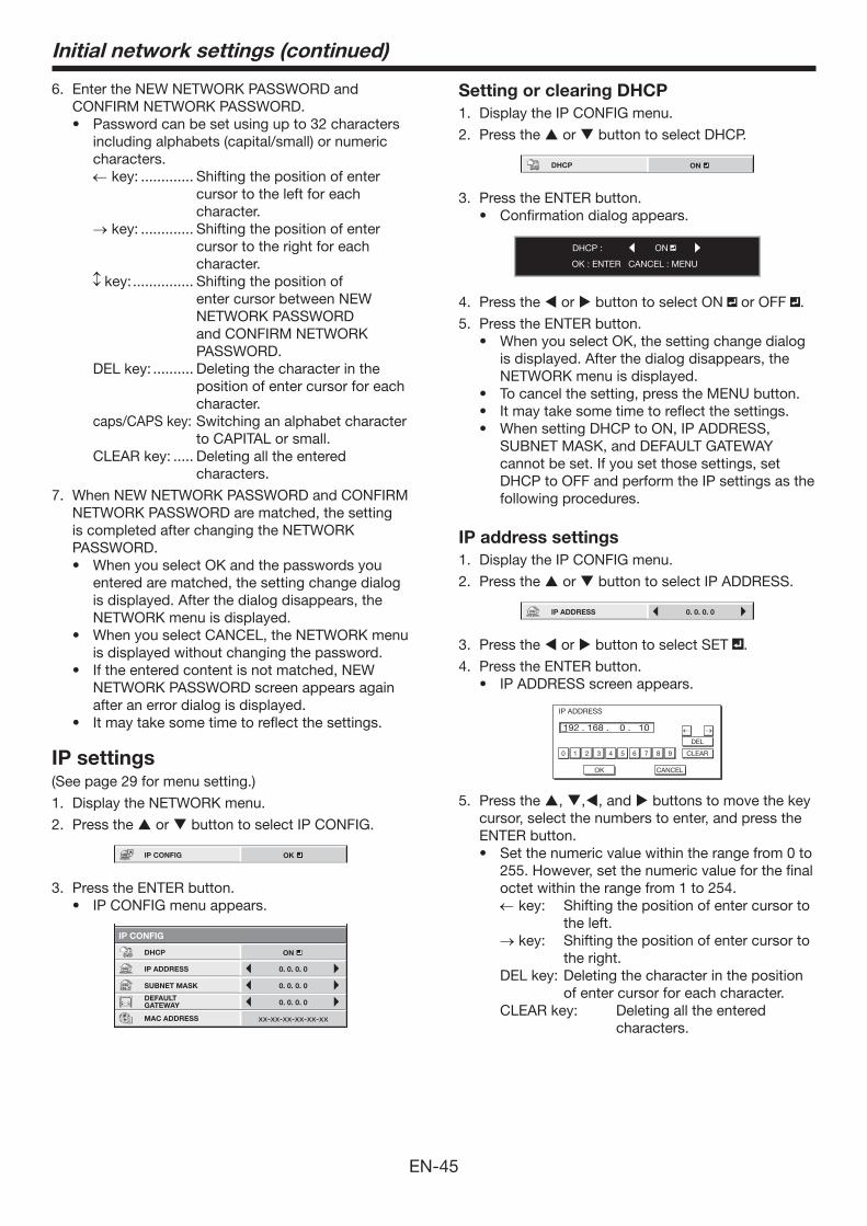
EN-45
6. Enter the NEW NETWORK PASSWORD and CONFIRM NETWORK PASSWORD.
including alphabets (capital/small) or numeric characters. key: ............. Shifting the position of enter
cursor to the left for each character.
key: ............. Shifting the position of enter cursor to the right for each character.
key: ............... Shifting the position of enter cursor between NEW NETWORK PASSWORD and CONFIRM NETWORK PASSWORD.
DEL key: .......... Deleting the character in the position of enter cursor for each character.
caps/CAPS key: Switching an alphabet character to CAPITAL or small.
CLEAR key: ..... Deleting all the entered characters.
7. When NEW NETWORK PASSWORD and CONFIRM NETWORK PASSWORD are matched, the setting is completed after changing the NETWORK PASSWORD.
entered are matched, the setting change dialog is displayed. After the dialog disappears, the NETWORK menu is displayed.
is displayed without changing the password.
NETWORK PASSWORD screen appears again after an error dialog is displayed.
IP settings(See page 29 for menu setting.)
1. Display the NETWORK menu.
2. Press the or button to select IP CONFIG.
IP CONFIG OK
3. Press the ENTER button.
IP CONFIG
DHCP
IP ADDRESS
SUBNET MASK
DEFAULT GATEWAY 0. 0. 0. 0
0. 0. 0. 0
0. 0. 0. 0
MAC ADDRESS
ON
Initial network settings (continued)
Setting or clearing DHCP
1. Display the IP CONFIG menu.
2. Press the or button to select DHCP.
DHCP ON
3. Press the ENTER button.
DHCP :
OK : ENTER CANCEL : MENU
ON
4. Press the or button to select ON or OFF .
5. Press the ENTER button.
is displayed. After the dialog disappears, the NETWORK menu is displayed.
SUBNET MASK, and DEFAULT GATEWAY cannot be set. If you set those settings, set DHCP to OFF and perform the IP settings as the following procedures.
IP address settings
1. Display the IP CONFIG menu.
2. Press the or button to select IP ADDRESS.
IP ADDRESS 0. 0. 0. 0
3. Press the or button to select SET .
4. Press the ENTER button.
IP ADDRESS
192 . 168 . 0 . 10
0
OK
CLEAR
DEL
CANCEL
1 2 3 4 5 6 7 8 9
5. Press the , ,, and buttons to move the key cursor, select the numbers to enter, and press the ENTER button.
255. However, set the numeric value for the final octet within the range from 1 to 254.
key: Shifting the position of enter cursor to the left.
key: Shifting the position of enter cursor to the right.
DEL key: Deleting the character in the position of enter cursor for each character.
CLEAR key: Deleting all the entered characters.
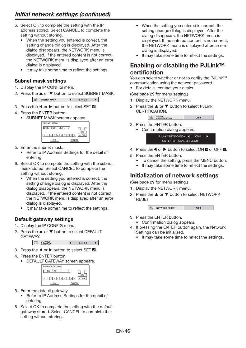
EN-46
6. Select OK to complete the setting with the IP address stored. Select CANCEL to complete the setting without storing.
setting change dialog is displayed. After the dialog disappears, the NETWORK menu is displayed. If the entered content is not correct, the NETWORK menu is displayed after an error dialog is displayed.
Subnet mask settings
1. Display the IP CONFIG menu.
2. Press the or button to select SUBNET MASK.SUBNET MASK 0. 0. 0. 0
3. Press the or button to select SET .
4. Press the ENTER button.
SUBNET MASK
255 . 255 . 255 . 0
0
OK
CLEAR
DEL
CANCEL
1 2 3 4 5 6 7 8 9
5. Enter the subnet mask.
entering.
6. Select OK to complete the setting with the subnet mask stored. Select CANCEL to complete the setting without storing.
setting change dialog is displayed. After the dialog disappears, the NETWORK menu is displayed. If the entered content is not correct, the NETWORK menu is displayed after an error dialog is displayed.
Default gateway settings
1. Display the IP CONFIG menu.
2. Press the or button to select DEFAULT GATEWAY.
DEFAULT GATEWAY 0. 0. 0. 0
3. Press the or button to select SET .
4. Press the ENTER button.
DEFAULT GATEWAY
10 . 132 . 1 . 1
0
OK
CLEAR
DEL
CANCEL
1 2 3 4 5 6 7 8 9
5. Enter the default gateway.
entering.
6. Select OK to complete the setting with the default gateway stored. Select CANCEL to complete the setting without storing.
setting change dialog is displayed. After the dialog disappears, the NETWORK menu is displayed. If the entered content is not correct, the NETWORK menu is displayed after an error dialog is displayed.
Enabling or disabling the PJLink™
certificationYou can select whether or not to certify the PJLink™ communication using the network password.
(See page 29 for menu setting.)
1. Display the NETWORK menu.
2. Press the or button to select PJLink CERTIFICATION.
PJLink CERTIFICATION ON
3. Press the ENTER button.
PJLink CERTIFICATION :
OK : ENTER CANCEL : MENU
ON
4. Press the or button to select ON or OFF .
5. Press the ENTER button.
Initialization of network settings(See page 29 for menu setting.)
1. Display the NETWORK menu.
2. Press the or button to select NETWORK RESET.
NETWORK RESET OK
3. Press the ENTER button.
4. If pressing the ENTER button again, the Network Settings can be initialized.
Initial network settings (continued)
EN-47
How to use network function
LAN, configure the both IP Addresses in the same network group.
If connecting in different network group, be sure to use a router. As for the settings of a router, ask the network administrator.
are not correct, the communication may be unavailable. For the detail, consult the network administrator.
the projector, LAN function may be unavailable. See page 32 for the detail of standby mode.
Glossary
For more detail of the glossary below, refer to the technical book that is commercially available.
Term Description
DHCP
Abbreviation for Dynamic Host Configuration Protocol. This protocol automatically assigns IP Address to networked devices.
IP Address Numerical address to identify networked computers.
Subnet Mask
A numeric value to define the number of bits used for a network address of a divided network (or subnet) in an IP Address.
Default GatewayA server (or router) to communicate across networks (subnets) that are divided by Subnet Mask.
MAC Address
Abbreviation for Media Access Control Address. MAC Address is a unique ID number assigned to each network adapter. And this is based on which data are sent and received between network adapters.
Initial network settings (continued)
EN-48
This projector is equipped with a lamp to project images. This lamp is a consumable. It may burn out or its brightness may decrease during use. In such cases, replace the lamp with a new one as soon as possible. Be sure to replace the lamp with a new lamp sold separately that is exclusive to this projector. Contact your dealer for purchase of the lamp.
Spare lamp VLT-HC7800LP
Warning:
into the projector. Using the projector with any foreign object present inside may result in electric shock or fire. When you can’t remove the foreign object from the inside, contact your dealer for removal.
may cause explosion.
may also result in fire.
fragments.
off the power using the POWER button. After the lamp goes out, wait about two minutes until the intake and exhaust fans for cooling the lamp stop rotating. Then unplug the power cord, and wait at least one hour to allow the lamp to cool down enough to the touch.
Interval of lamp replacementThe recommended interval of lamp replacement is about 5000 hours*1*2 of consecutive use. Such interval differs depending on the operating environment and may be shorter than 5000 hours*1*2. Decrease in luminescence and/or color brightness indicates that the lamp needs to be replaced. When the lamp operation time exceeds 3750 hours*1,
will be lit red only) and the lamp replacement message will appear on the screen for one minute everytime the lamp is turned on. When the lamp has been used for about 4750 hours*1, the replacement message (LAMP REPLACEMENT) will appear on the screen for one minute every 25 hours*1 thereafter. When the lamp operation time exceeds 5000
hours*1*2, the projector automatically shuts off and can’t be used until the lamp is replaced and the lamp
operation time is reset.
*1: Duration when LAMP MODE of the INSTALLATION menu is set to LOW. When it is set to STANDARD, this duration will be shorted.
*2: When LAMP MODE is set to STANDARD, this duration will be shorted to 3000 hours.
Caution:
breakdown.
explode or fail to illuminate permanently because of an impact, scratch, or deterioration through use. The period of time until explosion or permanent failure to illuminate varies considerably from lamp to lamp, depending on operation conditions. Therefore, the lamp may explode soon after the start of use.
of lamp replacement appears, replace it with a new one immediately even if the lamp is still lighting normally.
the gas charged inside the lamp will diffuse inside or outside the projector. The gas inside the lamp contains mercury. Be careful not to breathe it or avoid it from entering your eye or mouth. If you should breathe it or if it should enter your eye or mouth, see a doctor immediately.
projector. Ask your dealer to replace the lamp and to inspect the inside of the projector. When you clean or replace the lamp by yourself, be sure to hold the handle of the lamp. You may get injured by glass fragments.
projector or option lamp to prevent glass fragments from scattering.
projector.
Replacing the lamp
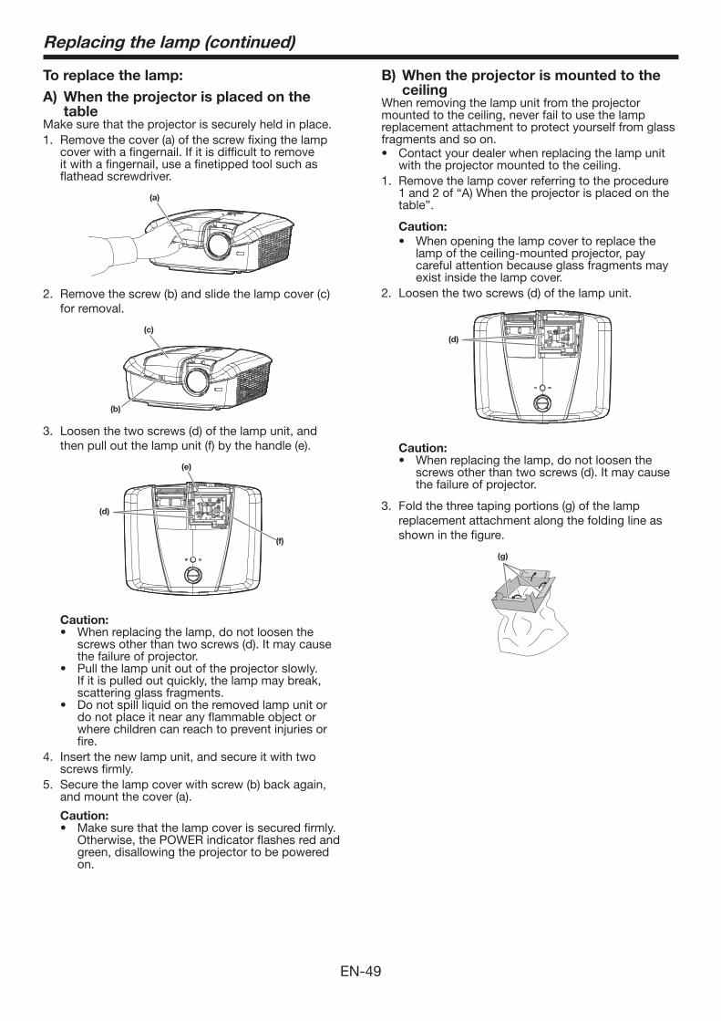
EN-49
Replacing the lamp (continued)
To replace the lamp:
A) When the projector is placed on the table
Make sure that the projector is securely held in place.1. Remove the cover (a) of the screw fixing the lamp
cover with a fingernail. If it is difficult to remove it with a fingernail, use a finetipped tool such as flathead screwdriver.
(a)
2. Remove the screw (b) and slide the lamp cover (c) for removal.
(c)
(b)
3. Loosen the two screws (d) of the lamp unit, and then pull out the lamp unit (f) by the handle (e).
(f)
(d)
(e)
Caution:
screws other than two screws (d). It may cause the failure of projector.
If it is pulled out quickly, the lamp may break, scattering glass fragments.
do not place it near any flammable object or where children can reach to prevent injuries or fire.
4. Insert the new lamp unit, and secure it with two screws firmly.
5. Secure the lamp cover with screw (b) back again, and mount the cover (a).
Caution:
Otherwise, the POWER indicator flashes red and green, disallowing the projector to be powered on.
B) When the projector is mounted to the ceiling
When removing the lamp unit from the projector mounted to the ceiling, never fail to use the lamp replacement attachment to protect yourself from glass fragments and so on.
with the projector mounted to the ceiling.1. Remove the lamp cover referring to the procedure
1 and 2 of “A) When the projector is placed on the table”.
Caution:
When opening the lamp cover to replace the lamp of the ceiling-mounted projector, pay careful attention because glass fragments may exist inside the lamp cover.
2. Loosen the two screws (d) of the lamp unit.
(d)
Caution:
screws other than two screws (d). It may cause the failure of projector.
3. Fold the three taping portions (g) of the lamp replacement attachment along the folding line as shown in the figure.
(g)
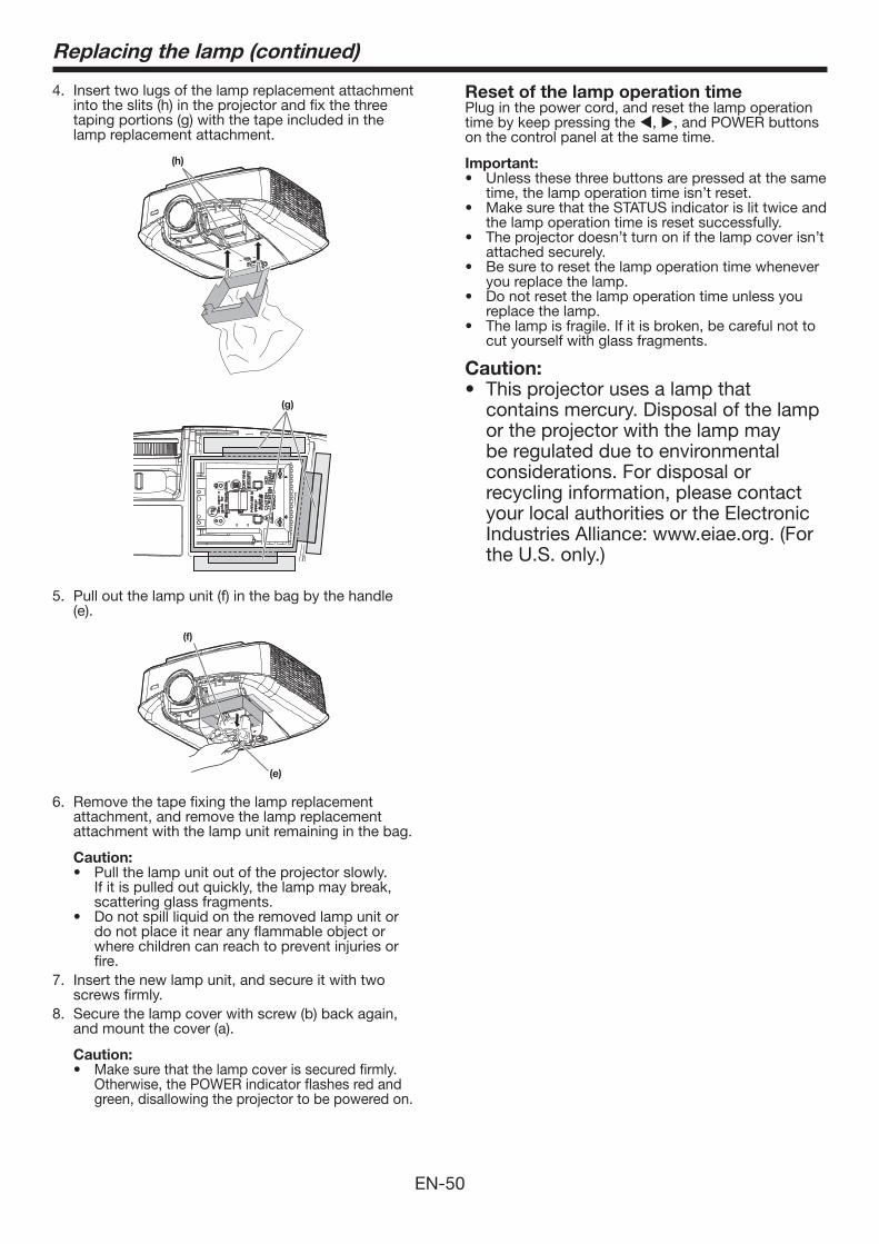
EN-50
Replacing the lamp (continued)
4. Insert two lugs of the lamp replacement attachment into the slits (h) in the projector and fix the three taping portions (g) with the tape included in the lamp replacement attachment.
(h)
(g)
5. Pull out the lamp unit (f) in the bag by the handle (e).
(f)
(e)
6. Remove the tape fixing the lamp replacement attachment, and remove the lamp replacement attachment with the lamp unit remaining in the bag.
Caution:
If it is pulled out quickly, the lamp may break, scattering glass fragments.
do not place it near any flammable object or where children can reach to prevent injuries or fire.
7. Insert the new lamp unit, and secure it with two screws firmly.
8. Secure the lamp cover with screw (b) back again, and mount the cover (a).
Caution:Make sure that the lamp cover is secured firmly. Otherwise, the POWER indicator flashes red and green, disallowing the projector to be powered on.
Reset of the lamp operation timePlug in the power cord, and reset the lamp operation time by keep pressing the , , and POWER buttons on the control panel at the same time.
Important:
time, the lamp operation time isn’t reset.
the lamp operation time is reset successfully.
attached securely.
you replace the lamp.
replace the lamp.
cut yourself with glass fragments.
Caution: This projector uses a lamp that
contains mercury. Disposal of the lamp or the projector with the lamp may be regulated due to environmental considerations. For disposal or recycling information, please contact your local authorities or the Electronic Industries Alliance: www.eiae.org. (For the U.S. only.)
EN-51
Warning:
and lens. Flammable substances may ignite causing fire or breakdown while the lamp is illuminating.
Caution:
on the projector.
inside, it may result in fire or malfunction.
Cleaning of the projector and the ventilation slotsUse a soft cloth to clean the projector and the ventilation grilles. When the grilles become dirty, wipe them with a soft cloth dampened with diluted mild detergent, and then wipe them with a dry cloth.
To protect the surface of the projector from fading or deteriorating:
Cleaning of the lensUse a standard lens-cleaning brush or a piece of lens tissue dampened with lens cleaning fluid. The lens surface is fragile. Use only recommended, nonabrasive lens-cleaning materials. Do not touch the lens with your fingers.
Maintenance
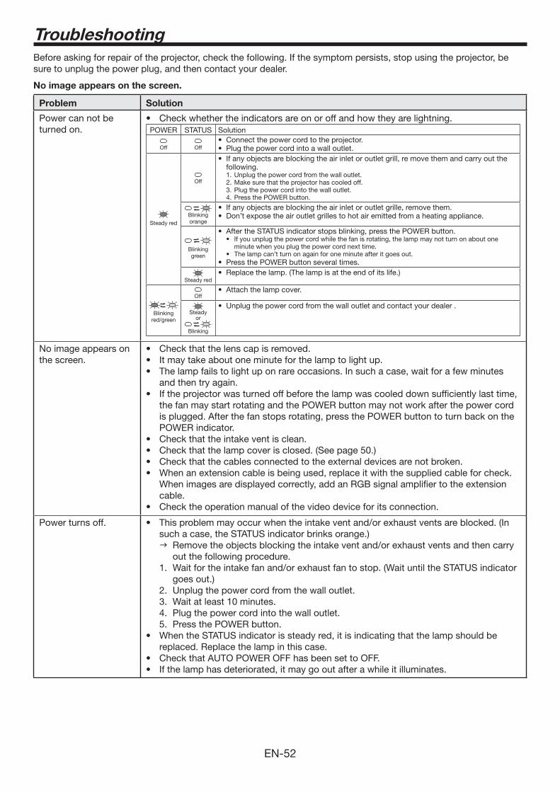
EN-52
Before asking for repair of the projector, check the following. If the symptom persists, stop using the projector, be sure to unplug the power plug, and then contact your dealer.
No image appears on the screen.
Problem Solution
Power can not be turned on. POWER STATUS Solution
Off Off
Steady red
Off
following.Unplug the power cord from the wall outlet.1. Make sure that the projector has cooled off.2. Plug the power cord into the wall outlet.3. Press the POWER button.4.
Blinking orange
Blinking green
If you unplug the power cord while the fan is rotating, the lamp may not turn on about one minute when you plug the power cord next time.The lamp can’t turn on again for one minute after it goes out.
Steady red
Blinking red/green
Off
Steadyor
Blinking
No image appears on the screen.
and then try again.
the fan may start rotating and the POWER button may not work after the power cord is plugged. After the fan stops rotating, press the POWER button to turn back on the POWER indicator.
When images are displayed correctly, add an RGB signal amplifier to the extension cable.
Power turns off.such a case, the STATUS indicator brinks orange.) Remove the objects blocking the intake vent and/or exhaust vents and then carry
out the following procedure.1. Wait for the intake fan and/or exhaust fan to stop. (Wait until the STATUS indicator
goes out.)2. Unplug the power cord from the wall outlet.3. Wait at least 10 minutes.4. Plug the power cord into the wall outlet.5. Press the POWER button.
replaced. Replace the lamp in this case.
Troubleshooting
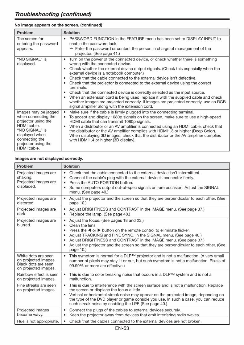
EN-53
No image appears on the screen. (continued)
Problem Solution
The screen for entering the password appears.
enable the password lock. Enter the password or contact the person in charge of management of the
projector. (See page 41.)“NO SIGNAL” is displayed.
Turn on the power of the connected device, or check whether there is something wrong with the connected device.Check whether the external device output signals. (Check this especially when the external device is a notebook computer.)Check that the cable connected to the external device isn’t defective.Check that the projector is connected to the external device using the correct terminals.Check that the connected device is correctly selected as the input source.When an extension cord is being used, replace it with the supplied cable and check whether images are projected correctly. If images are projected correctly, use an RGB signal amplifier along with the extension cord.
Images may be jagged when connecting the projector using the HDMI cable. “NO SIGNAL” is displayed when connecting the projector using the HDMI cable.
Make sure if the cable is firmly plugged into the connecting terminal.To accept and display 1080p signals on the screen, make sure to use a high-speed HDMI cable that can transmit 1080p signals.When a distributor or an AV amplifier is connected using an HDMI cable, check that the distributor or the AV amplifier complies with HDMI1.3 or higher (Deep Color). When displaying 3D images, check that the distributor or the AV amplifier complies with HDMI1.4 or higher (3D display).
Images are not displayed correctly.
Problem Solution
Projected images are shaking.Projected images are displaced.
Check that the cable connected to the external device isn’t intermittent.Connect the cable’s plug with the external device’s connector firmly.Press the AUTO POSITION button.Some computers output out-of-spec signals on rare occasion. Adjust the SIGNAL menu. (See page 40.)
Projected images are distorted.
Adjust the projector and the screen so that they are perpendicular to each other. (See page 10.)
Projected images are dark.
Adjust BRIGHTNESS and CONTRAST in the IMAGE menu. (See page 37.)Replace the lamp. (See page 48.)
Projected images are blurred.
Adjust the focus. (See pages 18 and 23.)Clean the lens.Press the or button on the remote control to eliminate flicker.Adjust TRACKING and FINE SYNC. in the SIGNAL menu. (See page 40.)Adjust BRIGHTNESS and CONTRAST in the IMAGE menu. (See page 37.)Adjust the projector and the screen so that they are perpendicular to each other. (See page 10.)
White dots are seenon projected images.Black dots are seen on projected images.
number of pixels may stay lit or out, but such symptom is not a malfunction. Pixels of
Rainbow effect is seenon projected images.
This is due to color breaking noise that occurs in a DLP™ system and is not a malfunction.
Fine streaks are seen on projected images.
This is due to interference with the screen surface and is not a malfunction. Replace the screen or displace the focus a little.Vertical or horizontal streak noise may appear on the projected image, depending on the type of the DVD player or game console you use. In such a case, you can reduce such streak noise by enabling the LPF. (See page 40.)
Projected images become wavy.
Connect the plugs of the cables to external devices securely.Keep the projector away from devices that emit interfering radio waves.
Hue is not appropriate. Check that the cables connected to the external devices are not broken.
Troubleshooting (continued)
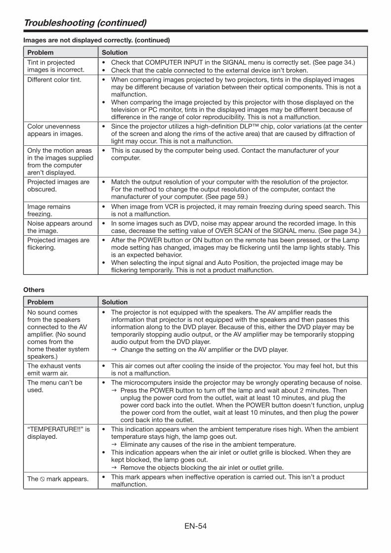
EN-54
Others
Problem Solution
No sound comes from the speakers connected to the AV amplifier. (No sound comes from the home theater system speakers.)
The projector is not equipped with the speakers. The AV amplifier reads the information that projector is not equipped with the speakers and then passes this information along to the DVD player. Because of this, either the DVD player may be temporarily stopping audio output, or the AV amplifier may be temporarily stopping audio output from the DVD player. Change the setting on the AV amplifier or the DVD player.
The exhaust vents emit warm air.
This air comes out after cooling the inside of the projector. You may feel hot, but this is not a malfunction.
The menu can’t be used.
The microcomputers inside the projector may be wrongly operating because of noise. Press the POWER button to turn off the lamp and wait about 2 minutes. Then
unplug the power cord from the outlet, wait at least 10 minutes, and plug the power cord back into the outlet. When the POWER button doesn't function, unplug the power cord from the outlet, wait at least 10 minutes, and then plug the power cord back into the outlet.
“TEMPERATURE!!” is displayed.
This indication appears when the ambient temperature rises high. When the ambient temperature stays high, the lamp goes out. Eliminate any causes of the rise in the ambient temperature.This indication appears when the air inlet or outlet grille is blocked. When they are kept blocked, the lamp goes out. Remove the objects blocking the air inlet or outlet grille.
The mark appears. This mark appears when ineffective operation is carried out. This isn’t a product malfunction.
Troubleshooting (continued)
Images are not displayed correctly. (continued)
Problem Solution
Tint in projected images is incorrect.
Check that COMPUTER INPUT in the SIGNAL menu is correctly set. (See page 34.)Check that the cable connected to the external device isn’t broken.
Different color tint. When comparing images projected by two projectors, tints in the displayed images may be different because of variation between their optical components. This is not a malfunction.When comparing the image projected by this projector with those displayed on the television or PC monitor, tints in the displayed images may be different because of difference in the range of color reproducibility. This is not a malfunction.
Color unevenness appears in images.
Since the projector utilizes a high-definition DLP™ chip, color variations (at the center of the screen and along the rims of the active area) that are caused by diffraction of light may occur. This is not a malfunction.
Only the motion areas in the images supplied from the computer aren’t displayed.
This is caused by the computer being used. Contact the manufacturer of your computer.
Projected images are obscured.
Match the output resolution of your computer with the resolution of the projector. For the method to change the output resolution of the computer, contact the manufacturer of your computer. (See page 59.)
Image remains freezing.
When image from VCR is projected, it may remain freezing during speed search. This is not a malfunction.
Noise appears around the image.
In some images such as DVD, noise may appear around the recorded image. In this case, decrease the setting value of OVER SCAN of the SIGNAL menu. (See page 34.)
Projected images areflickering.
After the POWER button or ON button on the remote has been pressed, or the Lamp mode setting has changed, images may be flickering until the lamp lights stably. This is an expected behavior.When selecting the input signal and Auto Position, the projected image may be flickering temporarily. This is not a product malfunction.
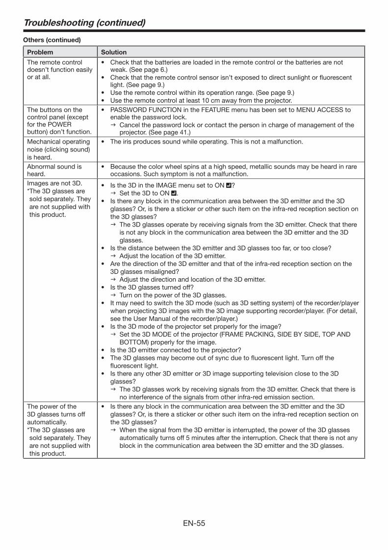
EN-55
Troubleshooting (continued)
Others (continued)
Problem Solution
The remote control doesn’t function easily or at all.
Check that the batteries are loaded in the remote control or the batteries are not weak. (See page 6.)Check that the remote control sensor isn’t exposed to direct sunlight or fluorescent light. (See page 9.)Use the remote control within its operation range. (See page 9.)Use the remote control at least 10 cm away from the projector.
The buttons on the control panel (except for the POWER button) don’t function.
PASSWORD FUNCTION in the FEATURE menu has been set to MENU ACCESS to enable the password lock. Cancel the password lock or contact the person in charge of management of the
projector. (See page 41.)Mechanical operating noise (clicking sound) is heard.Abnormal sound is heard.
Because the color wheel spins at a high speed, metallic sounds may be heard in rare occasions. Such symptom is not a malfunction.
Images are not 3D.* The 3D glasses are sold separately. They are not supplied with this product.
? Set the 3D to ON .
glasses? Or, is there a sticker or other such item on the infra-red reception section on the 3D glasses? The 3D glasses operate by receiving signals from the 3D emitter. Check that there
is not any block in the communication area between the 3D emitter and the 3D glasses.
Adjust the location of the 3D emitter.
3D glasses misaligned? Adjust the direction and location of the 3D emitter.
Turn on the power of the 3D glasses.
when projecting 3D images with the 3D image supporting recorder/player. (For detail, see the User Manual of the recorder/player.)
Set the 3D MODE of the projector (FRAME PACKING, SIDE BY SIDE, TOP AND BOTTOM) properly for the image.
fluorescent light.
glasses? The 3D glasses work by receiving signals from the 3D emitter. Check that there is
no interference of the signals from other infra-red emission section.The power of the 3D glasses turns off automatically.* The 3D glasses are sold separately. They are not supplied with this product.
glasses? Or, is there a sticker or other such item on the infra-red reception section on the 3D glasses? When the signal from the 3D emitter is interrupted, the power of the 3D glasses
automatically turns off 5 minutes after the interruption. Check that there is not any block in the communication area between the 3D emitter and the 3D glasses.
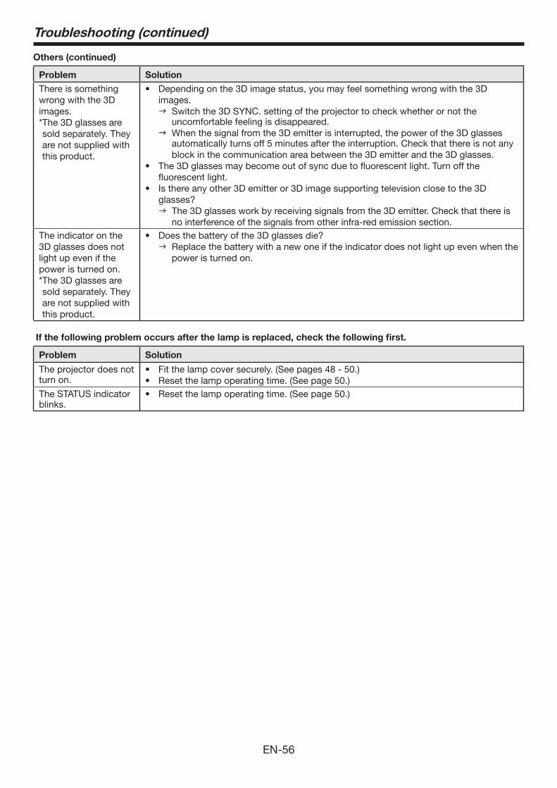
EN-56
Troubleshooting (continued)
Others (continued)
Problem Solution
There is something wrong with the 3D images.* The 3D glasses are sold separately. They are not supplied with this product.
images. Switch the 3D SYNC. setting of the projector to check whether or not the
uncomfortable feeling is disappeared. When the signal from the 3D emitter is interrupted, the power of the 3D glasses
automatically turns off 5 minutes after the interruption. Check that there is not any block in the communication area between the 3D emitter and the 3D glasses.
fluorescent light.
glasses? The 3D glasses work by receiving signals from the 3D emitter. Check that there is
no interference of the signals from other infra-red emission section.The indicator on the 3D glasses does not light up even if the power is turned on.* The 3D glasses are sold separately. They are not supplied with this product.
Replace the battery with a new one if the indicator does not light up even when the power is turned on.
If the following problem occurs after the lamp is replaced, check the following first.
Problem Solution
The projector does not turn on.
Fit the lamp cover securely. (See pages 48 - 50.) Reset the lamp operating time. (See page 50.)
The STATUS indicator blinks.
Reset the lamp operating time. (See page 50.)
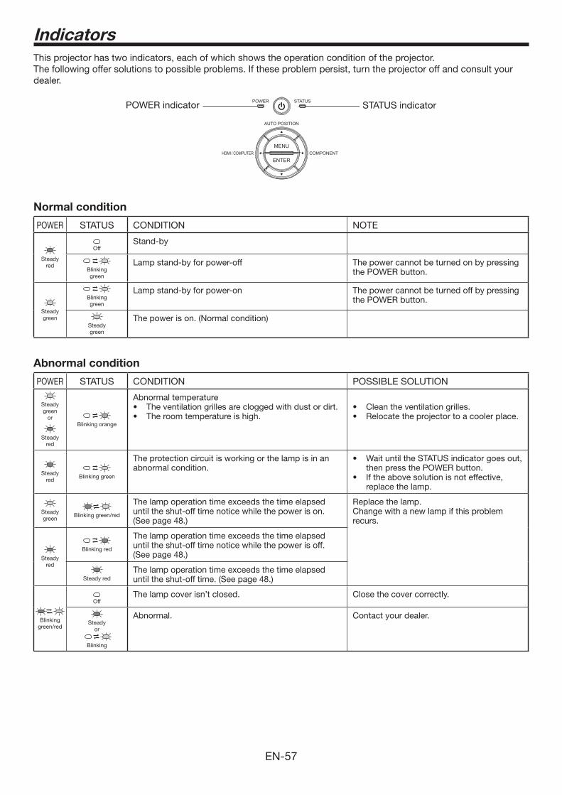
EN-57
Indicators
This projector has two indicators, each of which shows the operation condition of the projector.The following offer solutions to possible problems. If these problem persist, turn the projector off and consult your dealer.
STATUS indicatorPOWER indicator
Normal condition
POWER STATUS CONDITION NOTE
Steadyred
OffStand-by
Blinkinggreen
Lamp stand-by for power-off The power cannot be turned on by pressing the POWER button.
Steadygreen
Blinkinggreen
Lamp stand-by for power-on The power cannot be turned off by pressing the POWER button.
Steadygreen
The power is on. (Normal condition)
Abnormal condition
POWER STATUS CONDITION POSSIBLE SOLUTION
Steady green
or
Steady red
Blinking orange
Abnormal temperature
Steady red
Blinking green
The protection circuit is working or the lamp is in an abnormal condition. then press the POWER button.
replace the lamp.
Steady green
Blinking green/red
The lamp operation time exceeds the time elapsed until the shut-off time notice while the power is on. (See page 48.)
Replace the lamp.Change with a new lamp if this problem recurs.
Steady red
Blinking red
The lamp operation time exceeds the time elapsed until the shut-off time notice while the power is off. (See page 48.)
Steady redThe lamp operation time exceeds the time elapsed until the shut-off time. (See page 48.)
Blinking green/red
OffThe lamp cover isn’t closed. Close the cover correctly.
Steady or
Blinking
Abnormal. Contact your dealer.
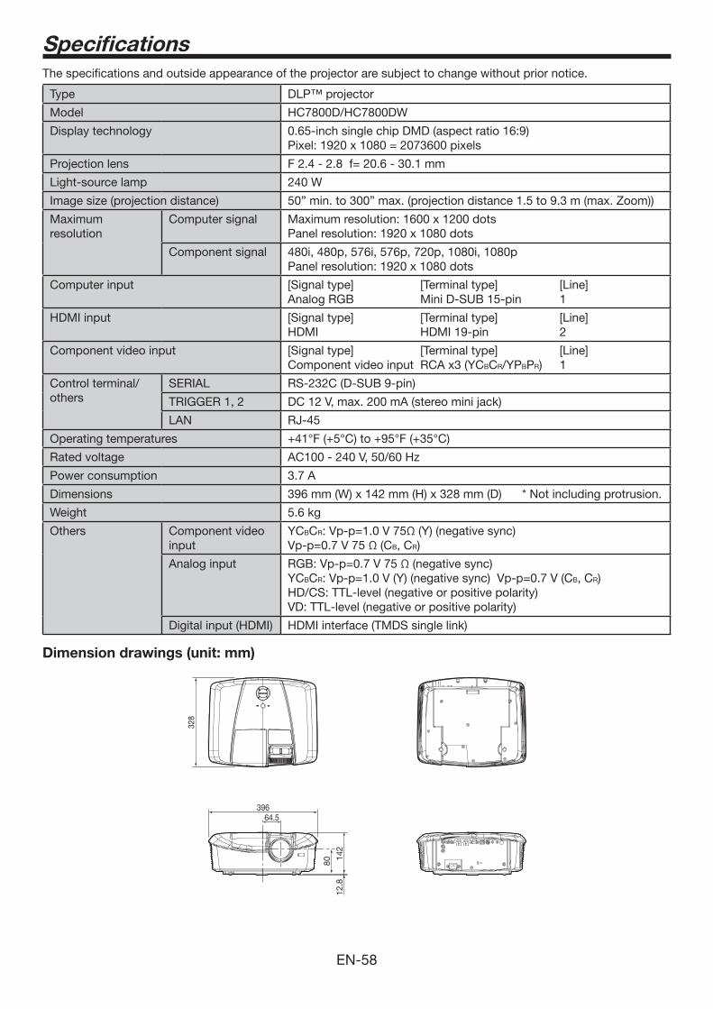
EN-58
The specifications and outside appearance of the projector are subject to change without prior notice.
Type DLP™ projector
Model HC7800D/HC7800DW
Display technology 0.65-inch single chip DMD (aspect ratio 16:9)Pixel: 1920 x 1080 = 2073600 pixels
Projection lens F 2.4 - 2.8 f= 20.6 - 30.1 mm
Light-source lamp 240 W
Image size (projection distance) 50” min. to 300” max. (projection distance 1.5 to 9.3 m (max. Zoom))
Maximum resolution
Computer signal Maximum resolution: 1600 x 1200 dotsPanel resolution: 1920 x 1080 dots
Component signal 480i, 480p, 576i, 576p, 720p, 1080i, 1080pPanel resolution: 1920 x 1080 dots
Computer input [Signal type] [Terminal type] [Line]Analog RGB Mini D-SUB 15-pin 1
HDMI input [Signal type] [Terminal type] [Line]HDMI HDMI 19-pin 2
Component video input [Signal type] [Terminal type] [Line]Component video input RCA x3 (YCBCR/YPBPR) 1
Control terminal/others
SERIAL RS-232C (D-SUB 9-pin)
TRIGGER 1, 2 DC 12 V, max. 200 mA (stereo mini jack)
LAN RJ-45
Operating temperatures
Rated voltage AC100 - 240 V, 50/60 Hz
Power consumption 3.7 A
Dimensions 396 mm (W) x 142 mm (H) x 328 mm (D) * Not including protrusion.
Weight 5.6 kg
Others Component video input
YCBCR: Vp-p=1.0 V 75Ω (Y) (negative sync)Vp-p=0.7 V 75 Ω (CB, CR)
Analog input RGB: Vp-p=0.7 V 75 Ω (negative sync)YCBCR: Vp-p=1.0 V (Y) (negative sync) Vp-p=0.7 V (CB, CR)HD/CS: TTL-level (negative or positive polarity)VD: TTL-level (negative or positive polarity)
Digital input (HDMI) HDMI interface (TMDS single link)
Dimension drawings (unit: mm)
39664.5
80
142
12.8
328
Specifications
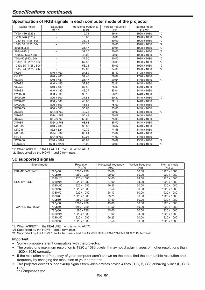
EN-59
Specifications (continued)
Specification of RGB signals in each computer mode of the projector
Signal mode Resolution(H x V)
Horizontal frequency (kHz)
Vertical frequency (Hz)
Normal mode(H x V)*1
TV60, 480i (525i) – 15.73 59.94 1920 x 1080 *2TV50, 576i (625i) – 15.63 50.00 1920 x 1080 *2 1080i 60 (1125i 60) – 33.75 60.00 1920 x 1080 *21080i 50 (1125i 50) – 28.13 50.00 1920 x 1080 *2480p (525p) – 31.47 59.94 1920 x 1080 *2576p (625p) – 31.25 50.00 1920 x 1080 *2720p 60 (750p 60) – 45.00 60.00 1920 x 1080 *2720p 50 (750p 50) – 37.50 50.00 1920 x 1080 *21080p 60 (1125p 60) – 67.50 60.00 1920 x 1080 *21080p 50 (1125p 50) – 56.25 50.00 1920 x 1080 *21080p 24 (1125p 24) – 27.00 24.00 1920 x 1080 *2PC98 640 x 400 24.82 56.42 1728 x 1080CGA70 640 x 400 31.47 70.09 1728 x 1080VGA60 640 x 480 31.47 59.94 1440 x 1080 *2VGA72 640 x 480 37.86 72.81 1440 x 1080VGA75 640 x 480 37.50 75.00 1440 x 1080VGA85 640 x 480 43.27 85.01 1440 x 1080SVGA56 800 x 600 35.16 56.25 1440 x 1080SVGA60 800 x 600 37.88 60.32 1440 x 1080 *2SVGA72 800 x 600 48.08 72.19 1440 x 1080SVGA75 800 x 600 46.88 75.00 1440 x 1080SVGA85 800 x 600 53.67 85.06 1440 x 1080XGA60 1024 x 768 48.36 60.00 1440 x 1080 *2XGA70 1024 x 768 56.48 70.07 1440 x 1080XGA75 1024 x 768 60.02 75.03 1440 x 1080XGA85 1024 x 768 68.68 85.00 1440 x 1080MAC13 640 x 480 35.00 66.67 1440 x 1080MAC16 832 x 624 49.72 74.55 1440 x 1080MAC19 1024 x 768 60.24 75.02 1440 x 1080HP75 1024 x 768 62.94 74.92 1440 x 1080SXGA60 1280 x 1024 63.98 60.02 1350 x 1080 *2UXGA60 1600 x 1200 75.00 60.00 1440 x 1080 *2
*1: When ASPECT in the FEATURE menu is set to AUTO.*2: Supported by the HDMI 1 and 2 terminals.
3D supported signals
Signal mode Resolution(H x V)
Horizontal frequency (kHz)
Vertical frequency (Hz)
Normal mode(H x V)*1
FRAME PACKING*2 720p50 1280 x 720 75.00 50.00 1920 x 1080720p60 1280 x 720 90.00 60.00 1920 x 10801080p24 1920 x 1080 54.00 24.00 1920 x 1080
SIDE BY SIDE*3 1080p24 1920 x 1080 27.00 24.00 1920 x 10801080p50 1920 x 1080 56.25 50.00 1920 x 10801080p60 1920 x 1080 67.50 60.00 1920 x 10801080i50 1920 x 1080 28.13 50.00 1920 x 10801080i60 1920 x 1080 33.75 60.00 1920 x 1080720p50 1280 x 720 37.50 50.00 1920 x 1080720p60 1280 x 720 45.00 60.00 1920 x 1080
TOP AND BOTTOM*3 720p50 1280 x 720 37.50 50.00 1920 x 1080720p60 1280 x 720 45.00 60.00 1920 x 10801080p24 1920 x 1080 27.00 24.00 1920 x 10801080p50 1920 x 1080 56.25 50.00 1920 x 10801080p60 1920 x 1080 67.50 60.00 1920 x 1080
*1: When ASPECT in the FEATURE menu is set to AUTO.*2: Supported by the HDMI 1 and 2 terminals.*3: Supported by the HDMI 1 and 2 terminals and the COMPUTER/COMPONENT VIDEO IN terminal.
Important:
1920 x 1080 correctly.
frequency by changing the resolution of your computer.
H, V). * : Composite Sync
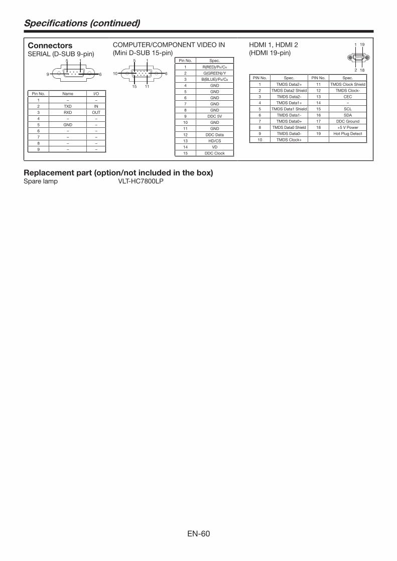
EN-60
Specifications (continued)
ConnectorsSERIAL (D-SUB 9-pin)
1 5
6 9
Pin No. Name I/O
1 – –
2 TXD IN
3 RXD OUT
4 – –
5 GND –
6 – –
7 – –
8 – –
9 – –
COMPUTER/COMPONENT VIDEO IN(Mini D-SUB 15-pin)
Pin No. Spec.
1 R(RED)/PR/CR
2 G(GREEN)/Y
3 B(BLUE)/PB/CB
4 GND
5 GND
6 GND
7 GND
8 GND
9 DDC 5V
10 GND
11 GND
12 DDC Data
13 HD/CS
14 VD
15 DDC Clock
HDMI 1, HDMI 2(HDMI 19-pin)
191
2 18
PIN No. Spec. PIN No. Spec.
1 11 TMDS Clock Shield
2 TMDS Data2 Shield 12 TMDS Clock-
3 TMDS Data2- 13 CEC
4 14 –
5 TMDS Data1 Shield 15 SCL
6 TMDS Data1- 16 SDA
7 17 DDC Ground
8 TMDS Data0 Shield 18
9 TMDS Data0- 19 Hot Plug Detect
10
Replacement part (option/not included in the box)Spare lamp VLT-HC7800LP
15
11
610
15

1 Zusho Baba, Nagaokakyo-City, Kyoto Japan
Ver. 1.0