Embed Size (px)
Citation preview
z2116_d2016_manual_V1.0
HD CCTV DVR
USER MANUAL
2MP ~ 5MP Video Recording
Please read instructions thoroughly before operation
and retain it for future reference.
For the actual display & operation, please refer to
your device in hand.
Free PC CMS software
(CMS Lite)
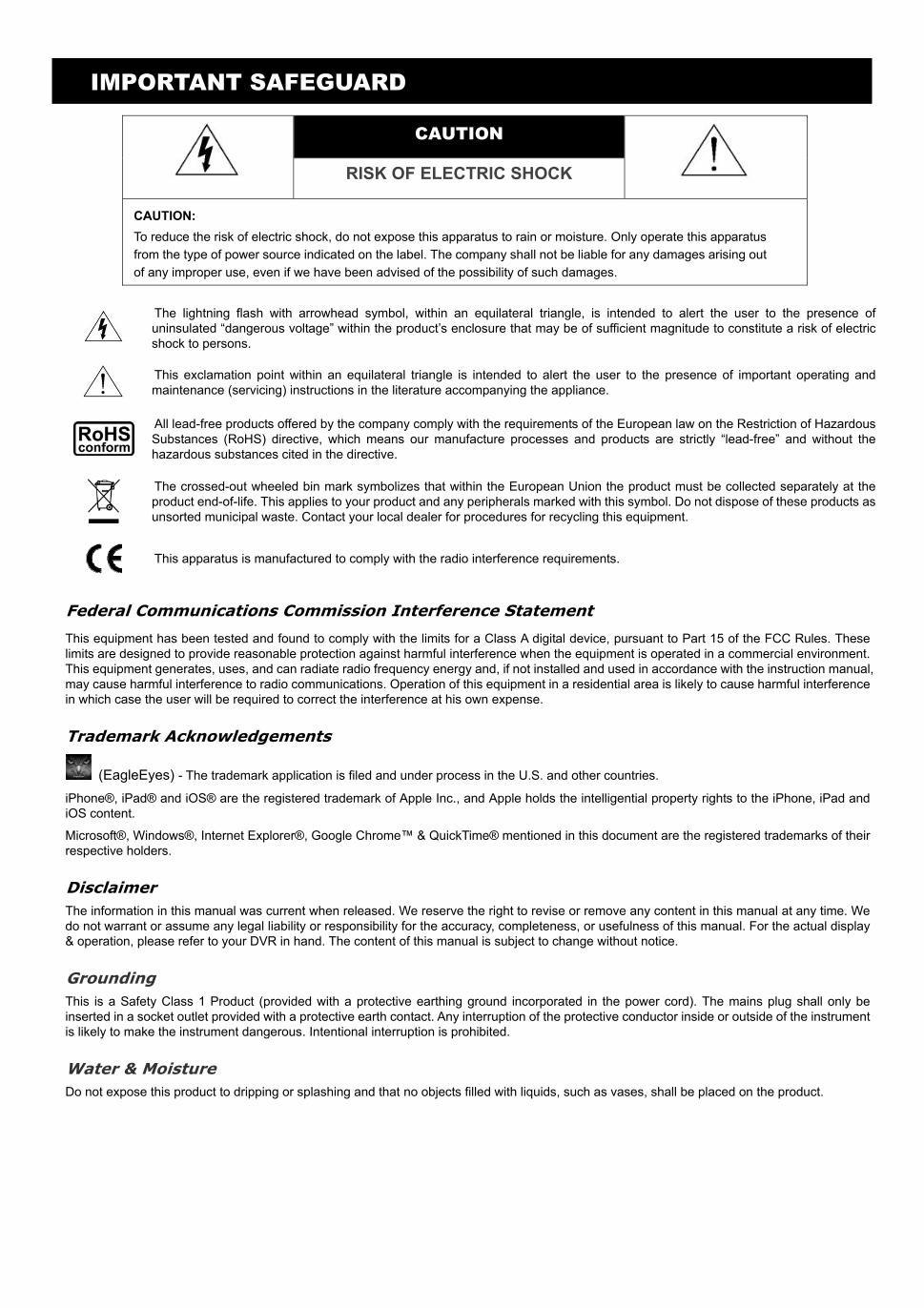
IMPORTANT SAFEGUARD
CAUTION
RISK OF ELECTRIC SHOCK
CAUTION:
To reduce the risk of electric shock, do not expose this apparatus to rain or moisture. Only operate this apparatus
from the type of power source indicated on the label. The company shall not be liable for any damages arising out
of any improper use, even if we have been advised of the possibility of such damages.
The lightning flash with arrowhead symbol, within an equilateral triangle, is intended to alert the user to the presence of uninsulated “dangerous voltage” within the product’s enclosure that may be of sufficient magnitude to constitute a risk of electric shock to persons.
This exclamation point within an equilateral triangle is intended to alert the user to the presence of important operating and maintenance (servicing) instructions in the literature accompanying the appliance.
All lead-free products offered by the company comply with the requirements of the European law on the Restriction of Hazardous Substances (RoHS) directive, which means our manufacture processes and products are strictly “lead-free” and without the hazardous substances cited in the directive.
The crossed-out wheeled bin mark symbolizes that within the European Union the product must be collected separately at the product end-of-life. This applies to your product and any peripherals marked with this symbol. Do not dispose of these products as unsorted municipal waste. Contact your local dealer for procedures for recycling this equipment.
This apparatus is manufactured to comply with the radio interference requirements.
Federal Communications Commission Interference Statement This equipment has been tested and found to comply with the limits for a Class A digital device, pursuant to Part 15 of the FCC Rules. These limits are designed to provide reasonable protection against harmful interference when the equipment is operated in a commercial environment. This equipment generates, uses, and can radiate radio frequency energy and, if not installed and used in accordance with the instruction manual, may cause harmful interference to radio communications. Operation of this equipment in a residential area is likely to cause harmful interference in which case the user will be required to correct the interference at his own expense.
Trademark Acknowledgements
(EagleEyes) - The trademark application is filed and under process in the U.S. and other countries.
iPhone®, iPad® and iOS® are the registered trademark of Apple Inc., and Apple holds the intelligential property rights to the iPhone, iPad and iOS content.
Microsoft®, Windows®, Internet Explorer®, Google Chrome™ & QuickTime® mentioned in this document are the registered trademarks of their respective holders.
Disclaimer The information in this manual was current when released. We reserve the right to revise or remove any content in this manual at any time. We do not warrant or assume any legal liability or responsibility for the accuracy, completeness, or usefulness of this manual. For the actual display & operation, please refer to your DVR in hand. The content of this manual is subject to change without notice.
Grounding This is a Safety Class 1 Product (provided with a protective earthing ground incorporated in the power cord). The mains plug shall only be inserted in a socket outlet provided with a protective earth contact. Any interruption of the protective conductor inside or outside of the instrument is likely to make the instrument dangerous. Intentional interruption is prohibited.
Water & Moisture Do not expose this product to dripping or splashing and that no objects filled with liquids, such as vases, shall be placed on the product.
MPEG4 Licensing THIS PRODUCT IS LICENSED UNDER THE MPEG-4 VISUAL PATENT PORTFOLIO LICENSE FOR THE PERSONAL AND NON-COMMERCIAL USE OF A CONSUMER FOR (i) ENCODING VIDEO IN COMPLIANCE WITH THE MPEG-4 VISUAL STANDARD (“MPEG-4 VIDEO”) AND/OR (ii) DECODING MPEG-4 VIDEO THAT WAS ENCODED BY A CONSUMER ENGAGED IN A PERSONAL AND NON-COMMERCIAL ACTIVITY AND/OR WAS OBTAINED FROM A VIDEO PROVIDER LICENSED BY MPEG LA TO PROVIDE MPEG-4 VIDEO. NO LICENSE IS GRANTED OR SHALL BE IMPLIED FOR ANY OTHER USE. ADDITIONAL INFORMATION INCLUDING THAT RELATING TO PROMOTIONAL INTERNAL AND COMMERCIAL USES AND LICENSING MAY BE OBTAINED FROM MPEG LA, LLC. SEE HTTP://WWW.MPEGLA.COM.
GPL Licensing
This product contains codes which are developed by Third-Party-Companies and which are subject to the GNU General Public License (“GPL”) or the GNU Lesser Public License (“LGPL”).
The GPL Code used in this product is released without warranty and is subject to the copyright of the corresponding author.
Further source codes which are subject to the GPL-licenses are available upon request.
We are pleased to provide our modifications to the Linux Kernel, as well as a few new commands, and some tools to get you into the code. The codes are provided on the FTP site, and please download them from the following site or you can check with your distributor:
http://download.dvrtw.com.tw/GPL/DVR/TVI/linux-3.3-fa.tgz
TABLE OF CONTENTS
1. HARDWARE OVERVIEW ................................................................................................................ 1
1.1 Package Content ................................................................................................................................................... 1
1.2 Front Panel ............................................................................................................................................................ 1
1.3 Rear Panel ............................................................................................................................................................. 2
2. CONNECTION AND SETUP ........................................................................................................... 4
2.1 SATA Hard Disk Installation .................................................................................................................................... 4
2.2 Camera Connection ............................................................................................................................................... 5
2.2.1 HD CCTV camera & our brand’s speed dome camera .................................................................................. 5
2.2.2 Other brand’s speed dome camera ............................................................................................................... 6
2.2.3 IP Camera...................................................................................................................................................... 6
2.3 DVR Power On ...................................................................................................................................................... 7
3. FOR INITIAL USE ............................................................................................................................ 8
3.1 Setup Wizard ......................................................................................................................................................... 8
3.2 Clear Hard Disk .................................................................................................................................................... 10
3.3 Change User Name and Password ...................................................................................................................... 11
4. USER INTERFACE ........................................................................................................................ 12
4.1 DVR Access ......................................................................................................................................................... 12
4.2 Live Page ............................................................................................................................................................. 12
4.2.1 DVR Status .................................................................................................................................................. 12
4.2.2 Channel Status ............................................................................................................................................ 13
4.2.3 Record-related Icons ................................................................................................................................... 13
4.3 Quick Menu Bar ................................................................................................................................................... 14
4.4 Main Menu ........................................................................................................................................................... 14
5. FREQUENTLY-USED FUNCTIONS .............................................................................................. 15
5.1 Key Lock / Unlock ................................................................................................................................................ 15
5.2 User Level Creation ............................................................................................................................................. 15
5.3 PTZ Control .......................................................................................................................................................... 17
5.4 Playback .............................................................................................................................................................. 19
5.4.1 Playback Control .......................................................................................................................................... 20
5.4.2 Event Search ............................................................................................................................................... 20
5.4.3 Audio Playback ............................................................................................................................................ 20
5.5 Video Backup ....................................................................................................................................................... 20
5.6 Video Playback on PC (.dv5) ............................................................................................................................... 21
5.6.1 Convert the file format to AVI ....................................................................................................................... 22
5.7 Digital Zoom ......................................................................................................................................................... 22
6. MAIN MENU .................................................................................................................................. 23
6.1 QUICK START ..................................................................................................................................................... 23
6.1.1 GENERAL ................................................................................................................................................... 23
6.1.2 TIME SETUP ............................................................................................................................................... 25
6.1.3 DAYLIGHT ................................................................................................................................................... 25
6.1.4 EaZy ............................................................................................................................................................ 26
6.2 SYSTEM .............................................................................................................................................................. 26
6.2.1 ACCOUNT ................................................................................................................................................... 26
6.2.2 TOOLS ......................................................................................................................................................... 27
6.2.3 SYSTEM INFO ............................................................................................................................................ 28
6.2.4 ONLINE ....................................................................................................................................................... 30
6.2.5 BACKUP DATA ............................................................................................................................................ 30
6.2.6 BACKUP LOG ............................................................................................................................................. 32
6.3 EVENT INFORMATION ....................................................................................................................................... 33
6.3.1 QUICK SEARCH ......................................................................................................................................... 33
6.3.2 HDD INFO ................................................................................................................................................... 34
6.3.3 EVENT LOG ................................................................................................................................................ 34
6.4 ADVANCED CONFIG ........................................................................................................................................... 35
6.4.1 CAMERA ..................................................................................................................................................... 35
6.4.2 DETECTION ................................................................................................................................................ 36
6.4.3 ALERT ......................................................................................................................................................... 38
6.4.4 NETWORK .................................................................................................................................................. 39
6.4.5 DISPLAY ...................................................................................................................................................... 41
6.4.6 RECORD ..................................................................................................................................................... 43
6.4.7 DEVICES ..................................................................................................................................................... 44
6.4.8 DCCS .......................................................................................................................................................... 44
6.4.9 IVS ............................................................................................................................................................... 45
6.4.10 NOTIFY ..................................................................................................................................................... 49
6.4.11 JOYSTICK ................................................................................................................................................. 54
6.5 SCHEDULE SETTING ......................................................................................................................................... 54
6.5.1 RECORD / DETECTION / ALARM IN / ALARM OUT / PUSH VIDEO / BUZZER ........................................ 54
6.5.2 REGULAR REPORT ................................................................................................................................... 55
6.5.3 AUTO BACKUP ........................................................................................................................................... 55
6.5.4 REGULAR REBOOT ................................................................................................................................... 57
7. REMOTE OPERATION .................................................................................................................. 58
7.1 Web Browser ....................................................................................................................................................... 58
7.1.1 IVS Statistics ................................................................................................................................................ 60
7.1.2 PTZ Panel .................................................................................................................................................... 61
7.2 Mobile Devices ..................................................................................................................................................... 62
7.2.1 Prerequisites ................................................................................................................................................ 62
7.2.2 Where to download ...................................................................................................................................... 62
7.2.3 Manual Setup .............................................................................................................................................. 62
APPENDIX 1 SPECIFICATIONS ....................................................................................................... 64
APPENDIX 2 PUSH VIDEO CONFIGURATION ............................................................................... 66
A2.1 Alarm Sensor Connection .................................................................................................................................. 66
A2.2 Configuration ..................................................................................................................................................... 67
A2.3 Enable Push Video ............................................................................................................................................ 67
A2.3.1 From iOS Mobile Device (iPhone / iPad) ................................................................................................... 67
A2.3.2 From Android Mobile Device ..................................................................................................................... 68
APPENDIX 3 COMPATIBLE USB FLASH DRIVE LIST ................................................................... 69
APPENDIX 4 COMPATIBLE SATA HDD LIST .................................................................................. 70
APPENDIX 5 MAIN MENU STRUCTURE ......................................................................................... 71
APPENDIX 6 DVR BATTERY REPLACEMENT ............................................................................... 73
APPENDIX 7 EAZY NETWORKING ................................................................................................. 74
A7.1 Via EagleEyes on iOS / Android Device ....................................................................................................... 74
A7.2 Via Internet Explorer on PC / Laptop ............................................................................................................ 80
A7.3 Icons ............................................................................................................................................................. 85
HARDWARE OVERVIEW
1
1. HARDWARE OVERVIEW
Note: The functions on the front panel and rear panel may vary, depending on the model you have.
1.1 Package Content
Standard Package
DVR HDD screws
Adapter & power cord Quick Start
Optional Accessories
USB Mouse IR Remote Controller
1.2 Front Panel
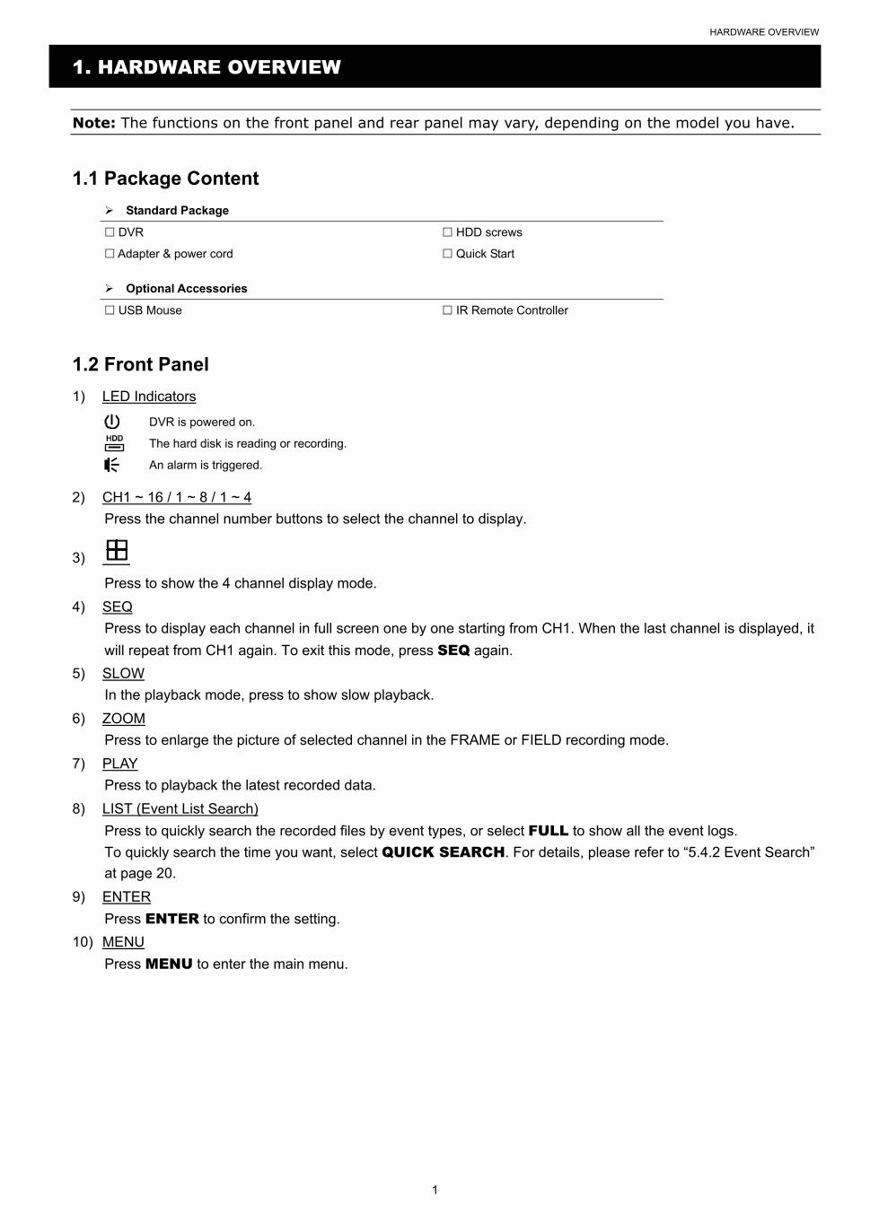
1) LED Indicators
DVR is powered on.
The hard disk is reading or recording.
An alarm is triggered.
2) CH1 ~ 16 / 1 ~ 8 / 1 ~ 4
Press the channel number buttons to select the channel to display.
3)
Press to show the 4 channel display mode.
4) SEQ
Press to display each channel in full screen one by one starting from CH1. When the last channel is displayed, it
will repeat from CH1 again. To exit this mode, press SEQ again.
5) SLOW
In the playback mode, press to show slow playback.
6) ZOOM
Press to enlarge the picture of selected channel in the FRAME or FIELD recording mode.
7) PLAY
Press to playback the latest recorded data.
8) LIST (Event List Search)
Press to quickly search the recorded files by event types, or select FULL to show all the event logs.
To quickly search the time you want, select QUICK SEARCH. For details, please refer to “5.4.2 Event Search”
at page 20.
9) ENTER
Press ENTER to confirm the setting.
10) MENU
Press MENU to enter the main menu.
HARDWARE OVERVIEW
2
11) (+ / PAUSE) / (- / STOP) / (REW) / (FF)
Press / / / to move up / down / left / right.
In the playback mode:
Press to pause playback.
Press to stop playback.
Press to fast forward.
Press to fast rewind.
12) AUDIO (SLOW + ZOOM)
Press SLOW + ZOOM to select live or playback audio from audio channel 1~4.
Live audio from audio channel 1~4 (indicated in white). Playback audio from audio channel 1~4
(indicated in yellow).
Audio channel unselected
13) P.T.Z. ( + SEQ)
Press + SEQ at the same time to enter / exit the PTZ control mode.
14) USB port
There are two USB ports on the front panel, one for connecting your USB mouse for mouse control, and the other
one for connecting your USB flash drive for video backup.
Note: It’s not allowed to have two USB mice or two USB flash drives connected on the front panel.
Note: For the compatible USB flash drive list, please refer to “APPENDIX 3 COMPATIBLE USB FLASH DRIVE LIST” at page 69.
1.3 Rear Panel
1) VIDEO IN
Connect to the video connector of a camera.
Note: The DVR will automatically detect the video system of the camera, please make sure that the cameras are properly connected to the DVR and power-supplied before the DVR is turned on.
2) VIDEO OUT
Connect to a CRT monitor for main or spot monitor output.
3) AUDIO IN
Connect to the audio connector of a camera if the camera supports audio recording.
Note: To make a video backup with audio, make sure the camera which supports the audio function is connected to the video-in channel and audio-in channel. For example, the audio data from audio CH1 will be recorded with the video data from video CH1. For 16CH models, the audio CH1 ~ CH4 are corresponding to video CH1 ~ CH4 respectively.
4) AUDIO OUT
Connect to a speaker with 1 mono audio output.
5) HDMI
Connect to the HDMI port of the monitor which supports HDMI video output for main or spot monitor output.
6) VGA
Connect to the VGA port of the monitor which supports VGA video output for main or spot monitor output.

HARDWARE OVERVIEW
3
7) USB port (USB 3.0 / For selected models only)
Used for connecting your USB flash drive for video backup.
Note: For the compatible USB flash drive list, please refer to “APPENDIX 3 COMPATIBLE USB FLASH DRIVE LIST” at page 69.
8) External I/O (Alarm IN / Alarm Out / RS485)
These ports are used to connect external devices (such as speed dome cameras or external alarm, etc).
9) LAN
Connect to Internet by LAN cable.
10) DC IN
Connect to the supplied adapter.
11) Power Switch (For selected models only) Switch to “—” to turn on the power, and “” to turn off the power.
CONNECTION AND SETUP
4
2. CONNECTION AND SETUP
Before the DVR is powered on, make sure you have installed a hard disk, connected at least one camera and a
HDMI monitor. For details, please refer to the following sections.
Note: The DVR is designed to automatically detect the video system of the connected cameras (NTSC or PAL). To make sure the system detection is correct, please check if the cameras are connected to the DVR and power-supplied before the DVR is powered on.
2.1 SATA Hard Disk Installation
At least a hard disk is necessary for the recorder to save video footage, and firmware upgrade might be failed if
there’s no hard disk installed in this recorder.
Either of the following two types of hard disk installation is applicable for your DVR model. Please check the
instructions below to see which installation method is the right one for your DVR to install a hard disk.
Note: Here takes an 8CH model as an example of how to connect a hard disk to your device. To know how many hard disks could be installed, please refer to the specifications of your device.
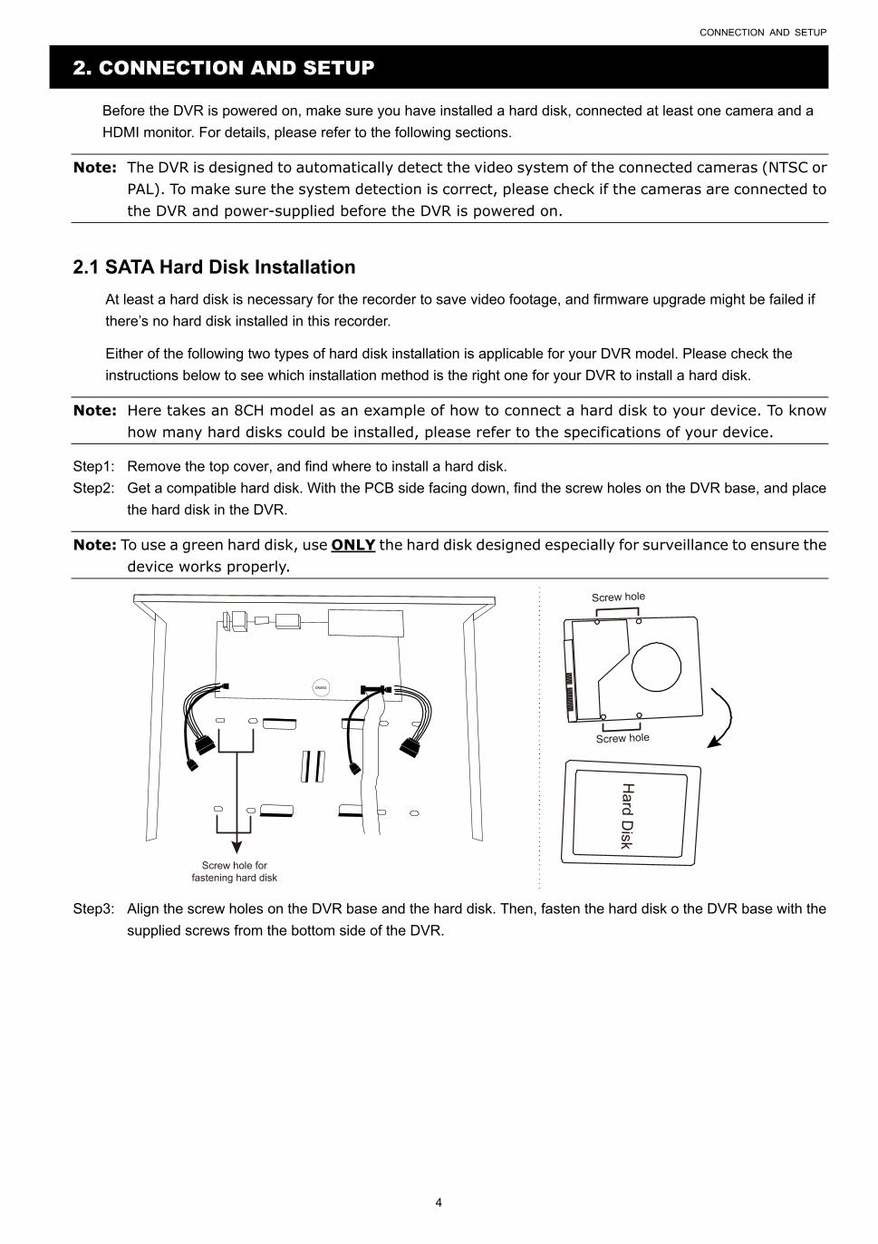
Step1: Remove the top cover, and find where to install a hard disk.
Step2: Get a compatible hard disk. With the PCB side facing down, find the screw holes on the DVR base, and place
the hard disk in the DVR.
Note: To use a green hard disk, use ONLY the hard disk designed especially for surveillance to ensure the device works properly.
CR2032
Screw hole forfastening hard disk
Hard D
isk
Screw hole
Screw hole
Step3: Align the screw holes on the DVR base and the hard disk. Then, fasten the hard disk o the DVR base with the
supplied screws from the bottom side of the DVR.
CONNECTION AND SETUP
5
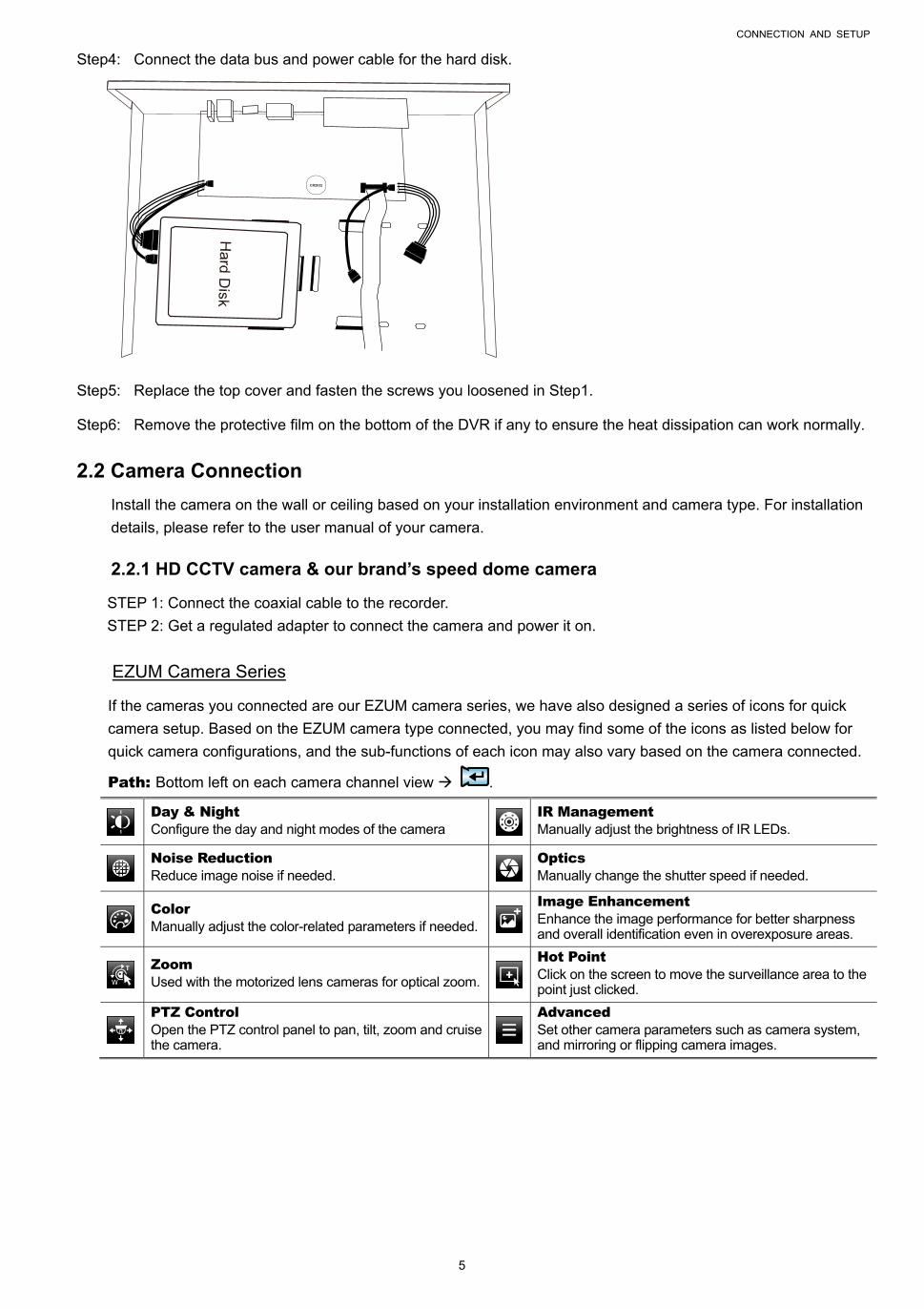
Step4: Connect the data bus and power cable for the hard disk.
CR2032
Step5: Replace the top cover and fasten the screws you loosened in Step1.
Step6: Remove the protective film on the bottom of the DVR if any to ensure the heat dissipation can work normally.
2.2 Camera Connection
Install the camera on the wall or ceiling based on your installation environment and camera type. For installation
details, please refer to the user manual of your camera.
2.2.1 HD CCTV camera & our brand’s speed dome camera
STEP 1: Connect the coaxial cable to the recorder.
STEP 2: Get a regulated adapter to connect the camera and power it on.
EZUM Camera Series
If the cameras you connected are our EZUM camera series, we have also designed a series of icons for quick
camera setup. Based on the EZUM camera type connected, you may find some of the icons as listed below for
quick camera configurations, and the sub-functions of each icon may also vary based on the camera connected.
Path: Bottom left on each camera channel view .
Day & Night Configure the day and night modes of the camera
IR Management Manually adjust the brightness of IR LEDs.
Noise Reduction Reduce image noise if needed.
Optics Manually change the shutter speed if needed.
Color Manually adjust the color-related parameters if needed.
Image Enhancement Enhance the image performance for better sharpness and overall identification even in overexposure areas.
Zoom Used with the motorized lens cameras for optical zoom.
Hot Point Click on the screen to move the surveillance area to the point just clicked.
PTZ Control Open the PTZ control panel to pan, tilt, zoom and cruise the camera.
Advanced Set other camera parameters such as camera system, and mirroring or flipping camera images.
CONNECTION AND SETUP
6
2.2.2 Other brand’s speed dome camera
Note: The recorder must support RS485 connection to connect a speed dome camera. Please check the specifications of your recorder for details.
STEP 1: Connect the coaxial cable to the recorder.
STEP 2: Find where the connectors of RS485-A and RS485-B are located on the recorder rear panel, and follow
the instructions of your camera manual to connect to the recorder. Then, power on the camera.
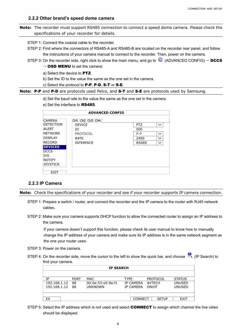
STEP 3: On the recorder side, right click to show the main menu, and go to (ADVANCED CONFIG) DCCS
OSD MENU to set the camera:
a) Select the device to PTZ.
b) Set the ID to the value the same as the one set in the camera.
c) Select the protocol to P-P, P-D, S-T or S-E.
Note: P-P and P-D are protocols used Pelco, and S-T and S-E are protocols used by Samsung.
d) Set the baud rate to the value the same as the one set in the camera.
e) Set the interface to RS485.
ADVANCED CONFIG
CAMERA CH1 CH2 CH3 CH4 DETECTION DEVICE PTZ ALERT ID 000 NETWORK PROTOCOL P-P DISPLAY RATE 2400 RECORD INTERFACE RS485 DEVICES DCCS IVS NOTIFY JOYSTICK
EXIT
2.2.3 IP Camera
Note: Check the specifications of your recorder and see if your recorder supports IP camera connection.
STEP 1: Prepare a switch / router, and connect the recorder and the IP camera to the router with RJ45 network
cables.
STEP 2: Make sure your camera supports DHCP function to allow the connected router to assign an IP address to
the camera.
If your camera doesn’t support this function, please check its user manual to know how to manually
change the IP address of your camera and make sure its IP address is in the same network segment as
the one your router uses.
STEP 3: Power on the camera.
STEP 4: On the recorder side, move the cursor to the left to show the quick bar, and choose (IP Search) to find your camera.
IP SEARCH
IP PORT MAC TYPE PROTOCOL STATUS 192.168.1.12 88 00:0e:53:e5:9a:f1 IP CAMERA AVTECH UNUSED 192.168.1.12 88 UNKNOWN IP CAMERA ONVIF UNUSED CONNECT SETUP EXIT
STEP 5: Select the IP address which is not used and select CONNECT to assign which channel the live video
should be displayed.
CONNECTION AND SETUP
7
2.3 DVR Power On
This device should be operated only with the type of power source indicated on the manufacturer’s label. Connect
the indicated AC power cord to the power adapter, and plug into an electrical outlet.
If your device has a power switch on the rear panel, turn it to “—“. The power LED will be on. If your device doesn’t
have a power switch on its rear panel, the power is on once the power source is connected.
Note: Before the DVR is powered on, make sure (1) the cameras are connected and power-supplied for the detection of the camera video system to be correct, and (2) a monitor is connected to the DVR for correct video output detection.
Note: To ensure that your DVR works constantly and properly, it's recommended to use an UPS, Uninterruptible Power Supply (Optional), for continuously operation.
Note: When your DVR is powered on, please check the chapter of “3. FOR INITIAL USE” in the user manual to know how to configure this device and change the default user name and password. To download the user manual, please scan the QR code on the first page, or go to www.surveillance-download.com/user/z2116.swf.
FOR INITIAL USE
8
3. FOR INITIAL USE
For the first time to power on this device, you might be prompted to:
Go through the setup wizard
Clear hard disk
Change default user name and password
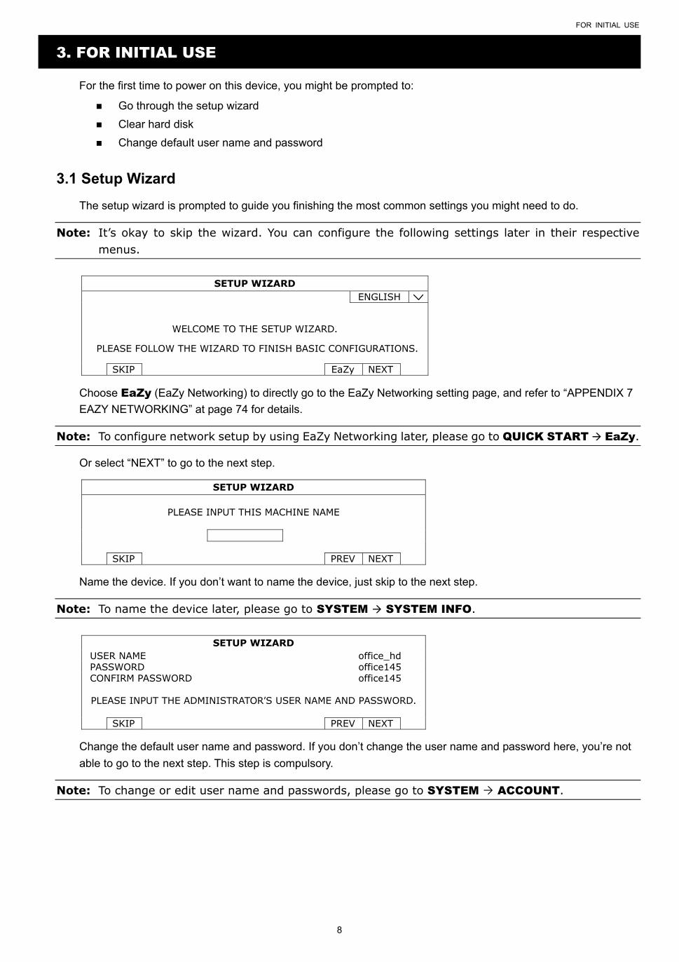
3.1 Setup Wizard
The setup wizard is prompted to guide you finishing the most common settings you might need to do.
Note: It’s okay to skip the wizard. You can configure the following settings later in their respective menus.
SETUP WIZARD ENGLISH
WELCOME TO THE SETUP WIZARD.
PLEASE FOLLOW THE WIZARD TO FINISH BASIC CONFIGURATIONS.
SKIP EaZy NEXT
Choose EaZy (EaZy Networking) to directly go to the EaZy Networking setting page, and refer to “APPENDIX 7
EAZY NETWORKING” at page 74 for details.
Note: To configure network setup by using EaZy Networking later, please go to QUICK START EaZy.
Or select “NEXT” to go to the next step.
SETUP WIZARD
PLEASE INPUT THIS MACHINE NAME
SKIP PREV NEXT
Name the device. If you don’t want to name the device, just skip to the next step.
Note: To name the device later, please go to SYSTEM SYSTEM INFO.
SETUP WIZARD USER NAME office_hd PASSWORD office145 CONFIRM PASSWORD office145 PLEASE INPUT THE ADMINISTRATOR’S USER NAME AND PASSWORD.
SKIP PREV NEXT
Change the default user name and password. If you don’t change the user name and password here, you’re not
able to go to the next step. This step is compulsory.
Note: To change or edit user name and passwords, please go to SYSTEM ACCOUNT.
FOR INITIAL USE
9
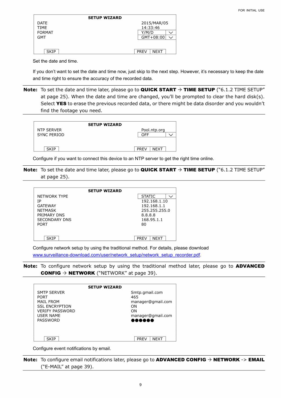
SETUP WIZARD DATE 2015/MAR/05 TIME 14:33:46 FORMAT Y/M/D GMT GMT+08:00
SKIP PREV NEXT
Set the date and time.
If you don’t want to set the date and time now, just skip to the next step. However, it’s necessary to keep the date
and time right to ensure the accuracy of the recorded data.
Note: To set the date and time later, please go to QUICK START TIME SETUP (“6.1.2 TIME SETUP” at page 25). When the date and time are changed, you’ll be prompted to clear the hard disk(s). Select YES to erase the previous recorded data, or there might be data disorder and you wouldn’t find the footage you need.
SETUP WIZARD
NTP SERVER Pool.ntp.org SYNC PERIOD OFF
SKIP PREV NEXT
Configure if you want to connect this device to an NTP server to get the right time online.
Note: To set the date and time later, please go to QUICK START TIME SETUP (“6.1.2 TIME SETUP” at page 25).
SETUP WIZARD
NETWORK TYPE STATIC IP 192.168.1.10 GATEWAY 192.168.1.1 NETMASK 255.255.255.0 PRIMARY DNS 8.8.8.8 SECONDARY DNS 168.95.1.1 PORT 80
SKIP PREV NEXT
Configure network setup by using the traditional method. For details, please download
www.surveillance-download.com/user/network_setup/network_setup_recorder.pdf.
Note: To configure network setup by using the traditional method later, please go to ADVANCED CONFIG NETWORK (“NETWORK” at page 39).
SETUP WIZARD
SMTP SERVER Smtp.gmail.com PORT 465 MAIL FROM [email protected] SSL ENCRYPTION ON VERIFY PASSWORD ON USER NAME [email protected] PASSWORD
SKIP PREV NEXT
Configure event notifications by email.
Note: To configure email notifications later, please go to ADVANCED CONFIG NETWORK -> EMAIL (“E-MAIL” at page 39).
FOR INITIAL USE
10
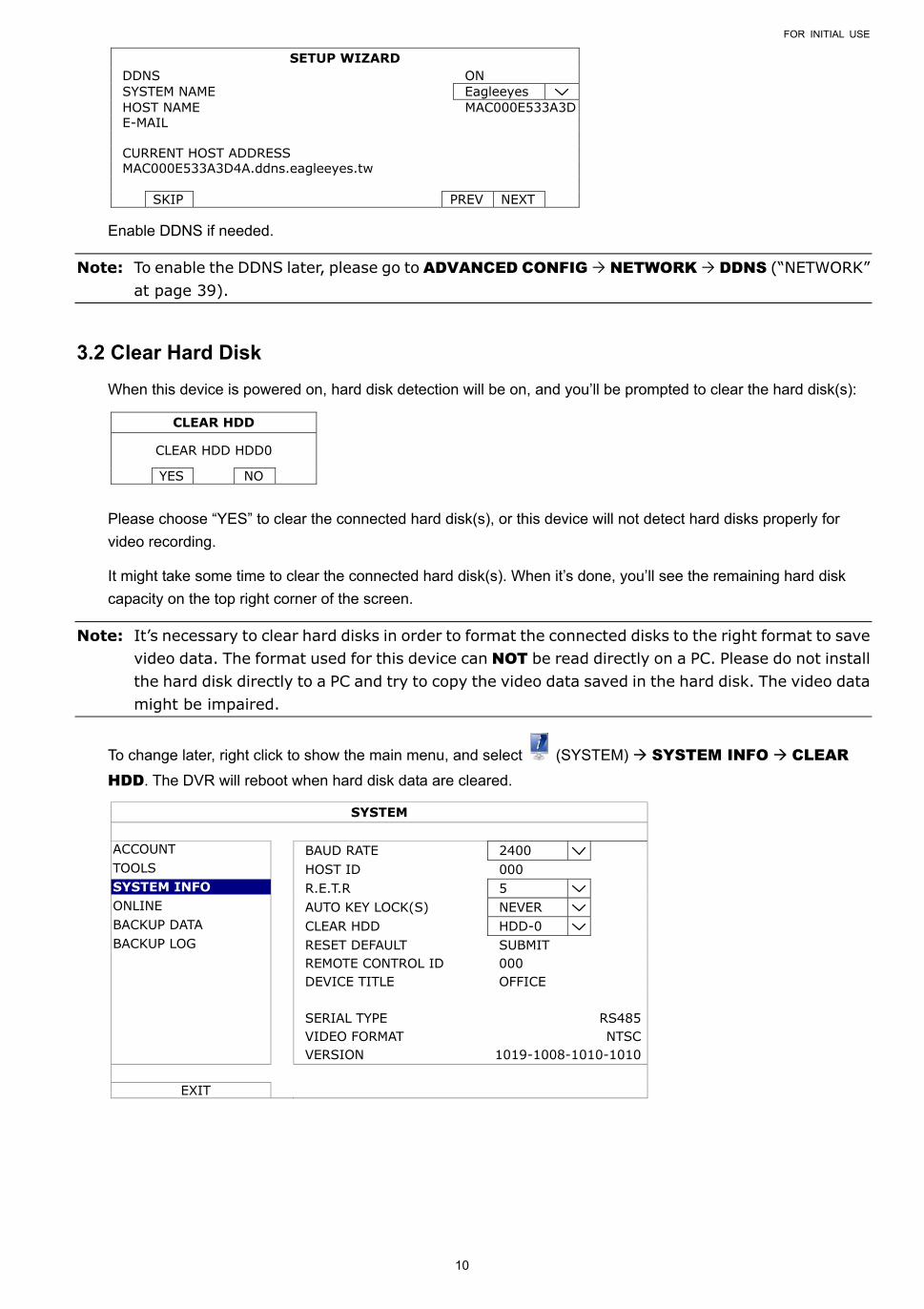
SETUP WIZARD DDNS ON SYSTEM NAME Eagleeyes HOST NAME MAC000E533A3D E-MAIL CURRENT HOST ADDRESS MAC000E533A3D4A.ddns.eagleeyes.tw
SKIP PREV NEXT
Enable DDNS if needed.
Note: To enable the DDNS later, please go to ADVANCED CONFIG NETWORK DDNS (“NETWORK” at page 39).
3.2 Clear Hard Disk
When this device is powered on, hard disk detection will be on, and you’ll be prompted to clear the hard disk(s):
CLEAR HDD
CLEAR HDD HDD0
YES NO
Please choose “YES” to clear the connected hard disk(s), or this device will not detect hard disks properly for
video recording.
It might take some time to clear the connected hard disk(s). When it’s done, you’ll see the remaining hard disk
capacity on the top right corner of the screen.
Note: It’s necessary to clear hard disks in order to format the connected disks to the right format to save video data. The format used for this device can NOT be read directly on a PC. Please do not install the hard disk directly to a PC and try to copy the video data saved in the hard disk. The video data might be impaired.
To change later, right click to show the main menu, and select (SYSTEM) SYSTEM INFO CLEAR HDD. The DVR will reboot when hard disk data are cleared.
SYSTEM
ACCOUNT BAUD RATE 2400 TOOLS HOST ID 000 SYSTEM INFO R.E.T.R 5 ONLINE AUTO KEY LOCK(S) NEVER BACKUP DATA CLEAR HDD HDD-0 BACKUP LOG RESET DEFAULT SUBMIT REMOTE CONTROL ID 000 DEVICE TITLE OFFICE SERIAL TYPE RS485 VIDEO FORMAT NTSC VERSION 1019-1008-1010-1010
EXIT
FOR INITIAL USE
11
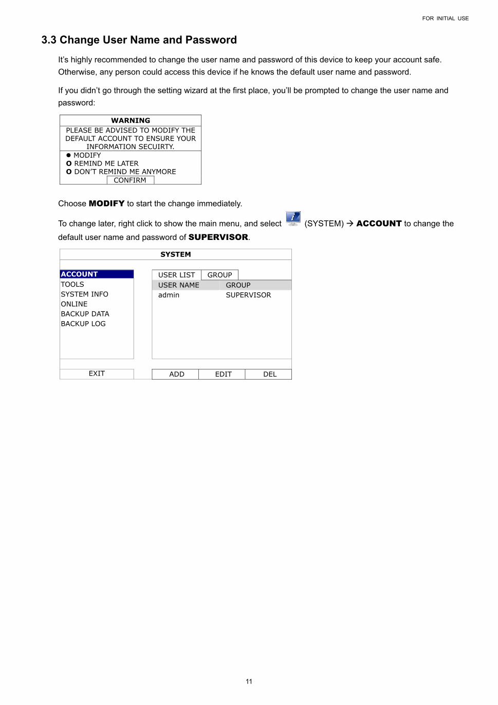
3.3 Change User Name and Password
It’s highly recommended to change the user name and password of this device to keep your account safe.
Otherwise, any person could access this device if he knows the default user name and password.
If you didn’t go through the setting wizard at the first place, you’ll be prompted to change the user name and
password:
WARNING PLEASE BE ADVISED TO MODIFY THE DEFAULT ACCOUNT TO ENSURE YOUR
INFORMATION SECUIRTY. MODIFY O REMIND ME LATER O DON’T REMIND ME ANYMORE
CONFIRM
Choose MODIFY to start the change immediately.
To change later, right click to show the main menu, and select (SYSTEM) ACCOUNT to change the
default user name and password of SUPERVISOR.
SYSTEM
ACCOUNT USER LIST GROUP TOOLS USER NAME GROUP SYSTEM INFO admin SUPERVISOR ONLINE BACKUP DATA BACKUP LOG
EXIT ADD EDIT DEL
USER INTERFACE
12
4. USER INTERFACE
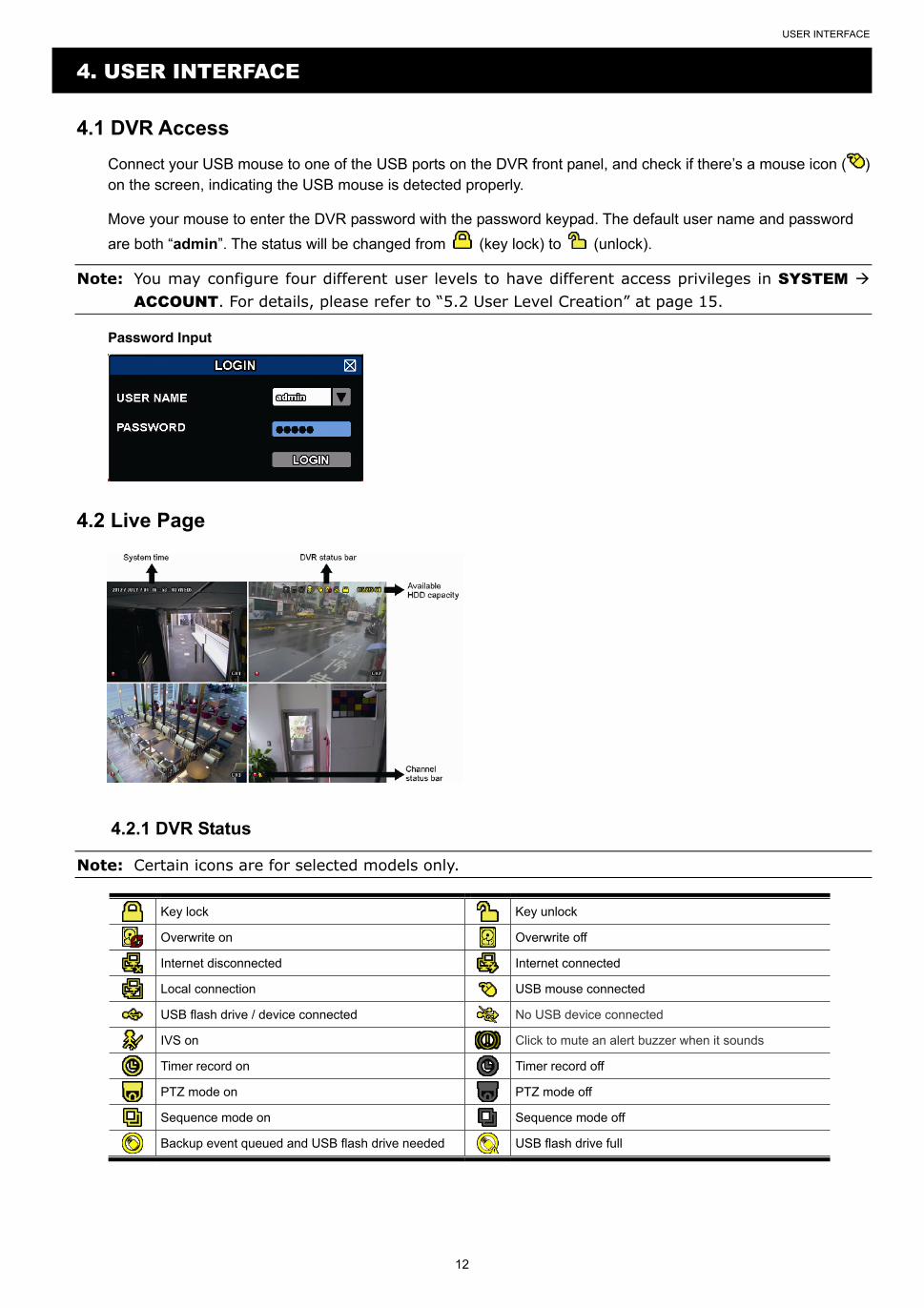
4.1 DVR Access
Connect your USB mouse to one of the USB ports on the DVR front panel, and check if there’s a mouse icon ( ) on the screen, indicating the USB mouse is detected properly.
Move your mouse to enter the DVR password with the password keypad. The default user name and password
are both “admin”. The status will be changed from (key lock) to (unlock).
Note: You may configure four different user levels to have different access privileges in SYSTEM ACCOUNT. For details, please refer to “5.2 User Level Creation” at page 15.
Password Input
4.2 Live Page
4.2.1 DVR Status
Note: Certain icons are for selected models only.
Key lock Key unlock
Overwrite on Overwrite off
Internet disconnected Internet connected
Local connection USB mouse connected
USB flash drive / device connected No USB device connected
IVS on Click to mute an alert buzzer when it sounds
Timer record on Timer record off
PTZ mode on PTZ mode off
Sequence mode on Sequence mode off
Backup event queued and USB flash drive needed USB flash drive full
USER INTERFACE
13
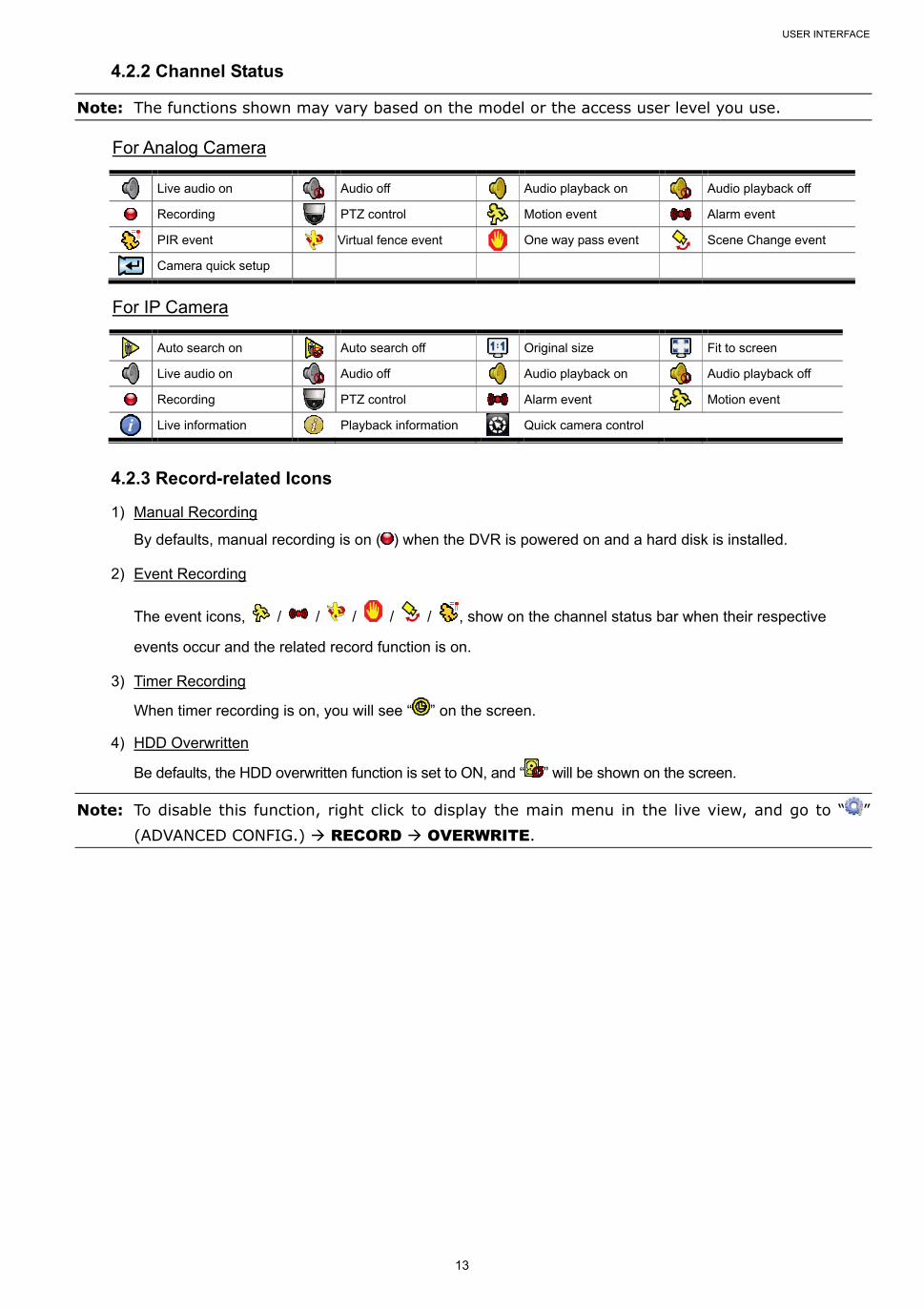
4.2.2 Channel Status
Note: The functions shown may vary based on the model or the access user level you use. For Analog Camera
Live audio on Audio off Audio playback on Audio playback off
Recording PTZ control Motion event Alarm event
PIR event Virtual fence event One way pass event Scene Change event
Camera quick setup
For IP Camera
Auto search on Auto search off Original size Fit to screen
Live audio on Audio off Audio playback on Audio playback off
Recording PTZ control Alarm event Motion event
Live information Playback information Quick camera control
4.2.3 Record-related Icons
1) Manual Recording
By defaults, manual recording is on ( ) when the DVR is powered on and a hard disk is installed.
2) Event Recording
The event icons, / / / / / , show on the channel status bar when their respective
events occur and the related record function is on.
3) Timer Recording
When timer recording is on, you will see “ ” on the screen.
4) HDD Overwritten
Be defaults, the HDD overwritten function is set to ON, and “ ” will be shown on the screen.
Note: To disable this function, right click to display the main menu in the live view, and go to “ ” (ADVANCED CONFIG.) RECORD OVERWRITE.
USER INTERFACE
14
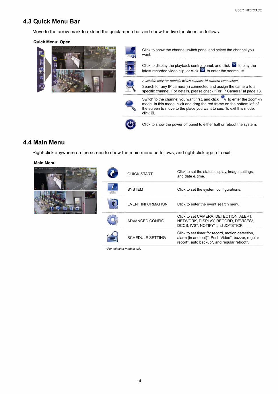
4.3 Quick Menu Bar
Move to the arrow mark to extend the quick menu bar and show the five functions as follows:
Quick Menu: Open
Click to show the channel switch panel and select the channel you want.
Click to display the playback control panel, and click to play the
latest recorded video clip, or click to enter the search list.
Available only for models which support IP camera connection.
Search for any IP camera(s) connected and assign the camera to a specific channel. For details, please check “For IP Camera” at page 13.
Switch to the channel you want first, and click to enter the zoom-in mode. In this mode, click and drag the red frame on the bottom left of the screen to move to the place you want to see. To exit this mode, click .
Click to show the power off panel to either halt or reboot the system.
4.4 Main Menu
Right-click anywhere on the screen to show the main menu as follows, and right-click again to exit.
Main Menu
QUICK START
Click to set the status display, image settings, and date & time.
SYSTEM Click to set the system configurations.
EVENT INFORMATION Click to enter the event search menu.
ADVANCED CONFIG
Click to set CAMERA, DETECTION, ALERT, NETWORK, DISPLAY, RECORD, DEVICES*, DCCS, IVS*, NOTIFY* and JOYSTICK.
SCHEDULE SETTING
Click to set timer for record, motion detection, alarm (in and out)*, Push Video*, buzzer, regular report*, auto backup*, and regular reboot*.
* For selected models only
FREQUENTLY-USED FUNCTIONS
15
5. FREQUENTLY-USED FUNCTIONS
5.1 Key Lock / Unlock
To lock or unlock local operation, click (unlock) or (lock) on the DVR status bar to change the status to
(lock) or (unlock).
To unlock local operation, you’ll be prompted to enter the user name and password to access.
Note: The default user name and password are both admin, which is the highest user level.
Note: Different user level has different access privilege for certain DVR functions. Please refer to “5.2 User Level Creation” at page 15.
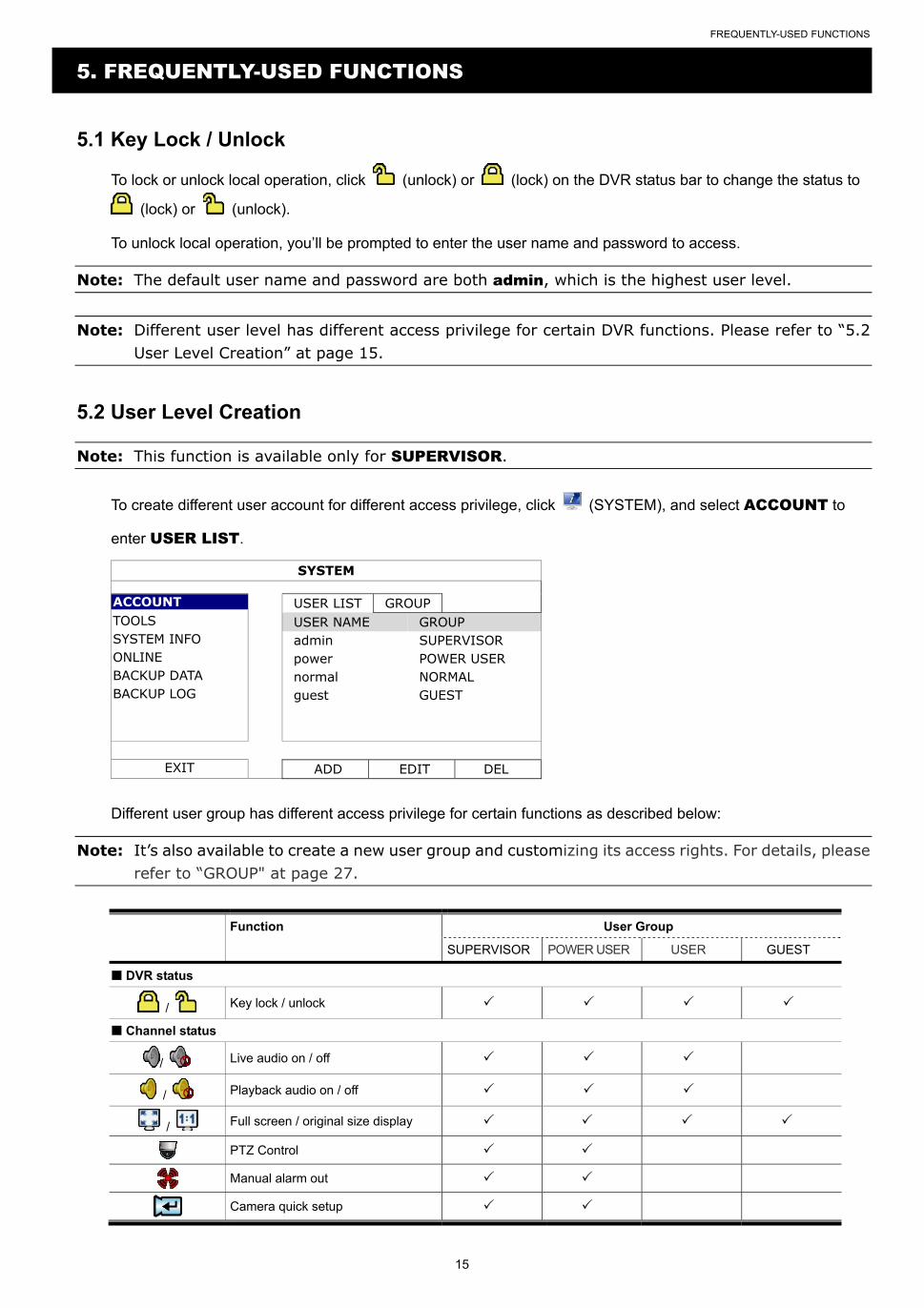
5.2 User Level Creation
Note: This function is available only for SUPERVISOR.
To create different user account for different access privilege, click (SYSTEM), and select ACCOUNT to
enter USER LIST.
SYSTEM
ACCOUNT USER LIST GROUP TOOLS USER NAME GROUP SYSTEM INFO admin SUPERVISOR ONLINE power POWER USER BACKUP DATA normal NORMAL BACKUP LOG guest GUEST
EXIT ADD EDIT DEL
Different user group has different access privilege for certain functions as described below:
Note: It’s also available to create a new user group and customizing its access rights. For details, please refer to “GROUP" at page 27.
Function User Group
SUPERVISOR POWER USER USER GUEST
DVR status
/ Key lock / unlock
Channel status
/ Live audio on / off
/ Playback audio on / off
/ Full screen / original size display
PTZ Control
Manual alarm out
Camera quick setup
FREQUENTLY-USED FUNCTIONS
16
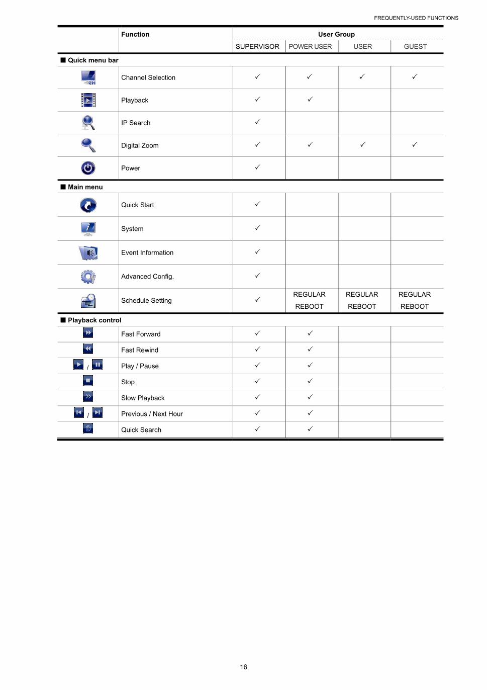
Function User Group
SUPERVISOR POWER USER USER GUEST
Quick menu bar
Channel Selection
Playback
IP Search
Digital Zoom
Power
Main menu
Quick Start
System
Event Information
Advanced Config.
Schedule Setting
REGULAR
REBOOT
REGULAR
REBOOT
REGULAR
REBOOT
Playback control
Fast Forward
Fast Rewind
/ Play / Pause
Stop
Slow Playback
/ Previous / Next Hour
Quick Search
FREQUENTLY-USED FUNCTIONS
17
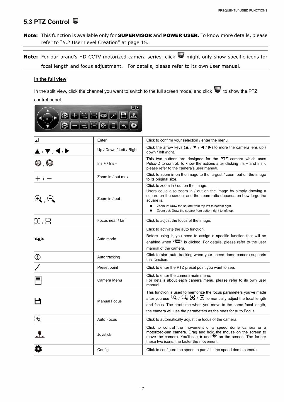
5.3 PTZ Control
Note: This function is available only for SUPERVISOR and POWER USER. To know more details, please refer to “5.2 User Level Creation” at page 15.
Note: For our brand’s HD CCTV motorized camera series, click might only show specific icons for
focal length and focus adjustment. For details, please refer to its own user manual.
In the full view
In the split view, click the channel you want to switch to the full screen mode, and click to show the PTZ
control panel.
Enter Click to confirm your selection / enter the menu.
/ / / Up / Down / Left / Right Click the arrow keys ( / / / ) to more the camera lens up / down / left /right.
/ Iris + / Iris - This two buttons are designed for the PTZ camera which uses Pelco-D to control. To know the actions after clicking Iris + and Iris -, please refer to the camera’s user manual.
+ / - Zoom in / out max Click to zoom in on the image to the largest / zoom out on the image to its original size.
/ Zoom in / out
Click to zoom in / out on the image. Users could also zoom in / out on the image by simply drawing a square on the screen, and the zoom ratio depends on how large the square is. Zoom in: Draw the square from top left to bottom right.
Zoom out: Draw the square from bottom right to left top.
/ Focus near / far Click to adjust the focus of the image.
Auto mode
Click to activate the auto function.
Before using it, you need to assign a specific function that will be
enabled when is clicked. For details, please refer to the user
manual of the camera.
Auto tracking Click to start auto tracking when your speed dome camera supports this function.
Preset point Click to enter the PTZ preset point you want to see.
Camera Menu
Click to enter the camera main menu. For details about each camera menu, please refer to its own user manual.
Manual Focus
This function is used to memorize the focus parameters you’ve made
after you use / / / to manually adjust the focal length
and focus. The next time when you move to the same focal length,
the camera will use the parameters as the ones for Auto Focus.
Auto Focus Click to automatically adjust the focus of the camera.
Joystick
Click to control the movement of a speed dome camera or a motorized-pan camera. Drag and hold the mouse on the screen to move the camera. You’ll see and on the screen. The farther these two icons, the faster the movement.
Config. Click to configure the speed to pan / tilt the speed dome camera.
FREQUENTLY-USED FUNCTIONS
18
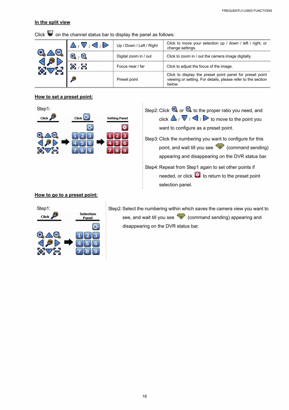
In the split view
Click on the channel status bar to display the panel as follows:
/ / / Up / Down / Left / Right Click to move your selection up / down / left / right, or change settings.
/ Digital zoom in / out Click to zoom in / out the camera image digitally.
/ Focus near / far Click to adjust the focus of the image.
Preset point Click to display the preset point panel for preset point viewing or setting. For details, please refer to the section below.
How to set a preset point:
Step1:
Step2: Click or to the proper ratio you need, and
click / / / to move to the point you
want to configure as a preset point.
Step3: Click the numbering you want to configure for this
point, and wait till you see (command sending)
appearing and disappearing on the DVR status bar.
Step4: Repeat from Step1 again to set other points if
needed, or click to return to the preset point
selection panel.
How to go to a preset point:
Step1:
Step2: Select the numbering within which saves the camera view you want to
see, and wait till you see (command sending) appearing and
disappearing on the DVR status bar.
FREQUENTLY-USED FUNCTIONS
19
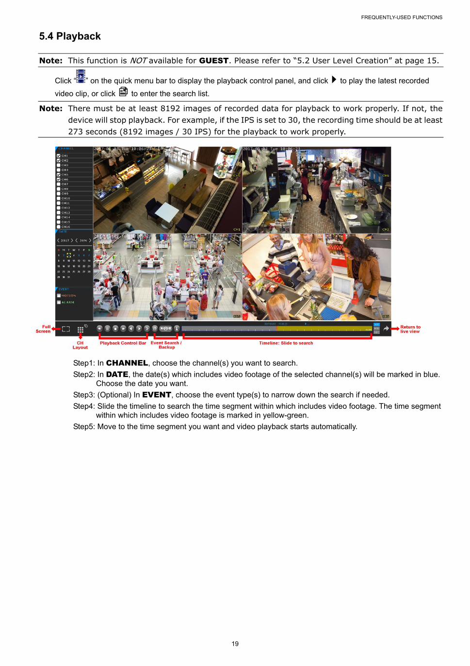
5.4 Playback
Note: This function is NOT available for GUEST. Please refer to “5.2 User Level Creation” at page 15.
Click “ ” on the quick menu bar to display the playback control panel, and click to play the latest recorded
video clip, or click to enter the search list.
Note: There must be at least 8192 images of recorded data for playback to work properly. If not, the device will stop playback. For example, if the IPS is set to 30, the recording time should be at least 273 seconds (8192 images / 30 IPS) for the playback to work properly.
Step1: In CHANNEL, choose the channel(s) you want to search.
Step2: In DATE, the date(s) which includes video footage of the selected channel(s) will be marked in blue. Choose the date you want.
Step3: (Optional) In EVENT, choose the event type(s) to narrow down the search if needed.
Step4: Slide the timeline to search the time segment within which includes video footage. The time segment within which includes video footage is marked in yellow-green.
Step5: Move to the time segment you want and video playback starts automatically.
FREQUENTLY-USED FUNCTIONS
20
5.4.1 Playback Control
Fast Forward Increase the speed for fast forward. Click once to get 4X speed forward and click
twice to get 8X speed, etc., and the maximum speed is 32X.
Fast Rewind Increase the speed for fast rewind. Click once to get 4X speed rewind and click
twice to get 8X speed, etc., and the maximum speed is 32X.
/ Play / Pause
Click to play the latest recorded video clip immediately, and click again to pause.
In the pause mode, click once to get one frame forward, and click to get
one frame rewind.
Stop Click to stop the video playback.
Slow Playback Click once to get 1/4X speed playback, and click twice to get 1/8X speed
playback.
/ Previous /
Next Hour
Click to jump to the next / previous time interval in an hour, for example, 11:00 ~
12:00 or 14:00 ~ 15:00, and start playing the earliest event video clip recorded
during this whole hour.
Repeat Click to set point A and point B in a video clip, and the system will play only the
specified range in that clip.
Backup Click to open the backup menu for video backup.
5.4.2 Event Search
Click to quickly search the recorded files by event types, or select FULL to show all the event logs.
To quickly search the time you want, select QUICK SEARCH.
5.4.3 Audio Playback
In the playback mode, click or on the channel status bar to play or mute audio recording.
Note: To make a video backup with audio, or play a recording with audio, make sure the camera which supports the audio function is connected to the video-in channel and audio-in channel. For example, the audio data from audio CH1 will be recorded with the video data from video CH1. For 16CH models, the audio CH1 ~ CH4 are corresponding to video CH1 ~ CH4 respectively.
5.5 Video Backup
Note: This function is available for SUPERVISOR. For details, please refer to “5.2 User Level Creation” at page 15.
Note: Before using your USB flash drive for video backup, please format it to "FAT32” first with your PC or laptop. For the list of compatible USB flash drives, please refer to “APPENDIX 3 COMPATIBLE USB FLASH DRIVE LIST” at page 69.
Note: Video backup could be made via a USB flash drive or the Internet. It’s NOT allowed to connect the hard disk to your PC / laptop directly for it may impair the recorded data saved in the hard disk.
FREQUENTLY-USED FUNCTIONS
21
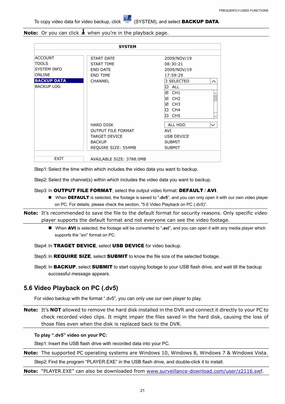
To copy video data for video backup, click (SYSTEM), and select BACKUP DATA.
Note: Or you can click when you’re in the playback page.
SYSTEM
ACCOUNT START DATE 2009/NOV/19 TOOLS START TIME 08:30:21 SYSTEM INFO END DATE 2009/NOV/19 ONLINE END TIME 17:59:29 BACKUP DATA CHANNEL 3 SELECTED BACKUP LOG ALL CH1 CH2 CH3 CH4 CH5 HARD DISK ALL HDD OUTPUT FILE FORMAT AVI TARGET DEVICE USB DEVICE BACKUP SUBMIT REQUIRE SIZE: 554MB SUBMIT
EXIT AVAILABLE SIZE: 3788.0MB
Step1: Select the time within which includes the video data you want to backup.
Step2: Select the channel(s) within which includes the video data you want to backup.
Step3: In OUTPUT FILE FORMAT, select the output video format: DEFAULT / AVI. When DEFAULT is selected, the footage is saved to ".dv5”, and you can only open it with our own video player
on PC. For details, please check the section, "5.6 Video Playback on PC (.dv5)”.
Note: It’s recommended to save the file to the default format for security reasons. Only specific video player supports the default format and not everyone can see the video footage. When AVI is selected, the footage will be converted to “.avi”, and you can open it with any media player which
supports the “avi” format on PC.
Step4: In TRAGET DEVICE, select USB DEVICE for video backup.
Step5: In REQUIRE SIZE, select SUBMIT to know the file size of the selected footage.
Step6: In BACKUP, select SUBMIT to start copying footage to your USB flash drive, and wait till the backup
successful message appears.
5.6 Video Playback on PC (.dv5)
For video backup with the format “.dv5”, you can only use our own player to play.
Note: It’s NOT allowed to remove the hard disk installed in the DVR and connect it directly to your PC to check recorded video clips. It might impair the files saved in the hard disk, causing the loss of those files even when the disk is replaced back to the DVR.
To play “.dv5” video on your PC:
Step1: Insert the USB flash drive with recorded data into your PC.
Note: The supported PC operating systems are Windows 10, Windows 8, Windows 7 & Windows Vista.
Step2: Find the program “PLAYER.EXE” in the USB flash drive, and double-click it to install.
Note: “PLAYER.EXE” can also be downloaded from www.surveillance-download.com/user/z2116.swf.
FREQUENTLY-USED FUNCTIONS
22
Step3: Run the program, VideoPlayer, and browse to where you save the recorded data.
Step4: Select the file you want to start video playback.
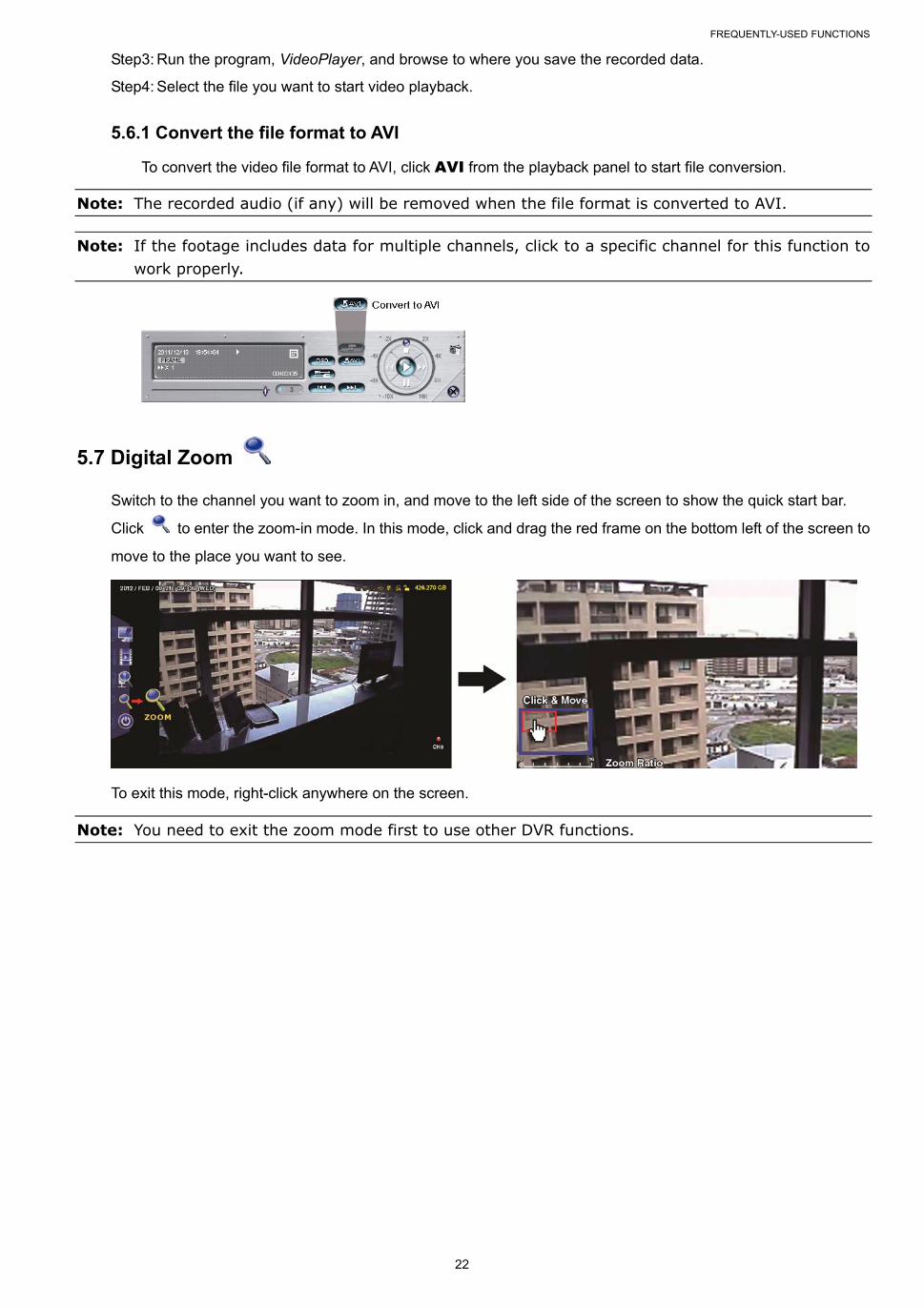
5.6.1 Convert the file format to AVI
To convert the video file format to AVI, click AVI from the playback panel to start file conversion.
Note: The recorded audio (if any) will be removed when the file format is converted to AVI.
Note: If the footage includes data for multiple channels, click to a specific channel for this function to work properly.
5.7 Digital Zoom
Switch to the channel you want to zoom in, and move to the left side of the screen to show the quick start bar.
Click to enter the zoom-in mode. In this mode, click and drag the red frame on the bottom left of the screen to
move to the place you want to see.
To exit this mode, right-click anywhere on the screen.
Note: You need to exit the zoom mode first to use other DVR functions.
MAIN MENU
23
6. MAIN MENU
6.1 QUICK START
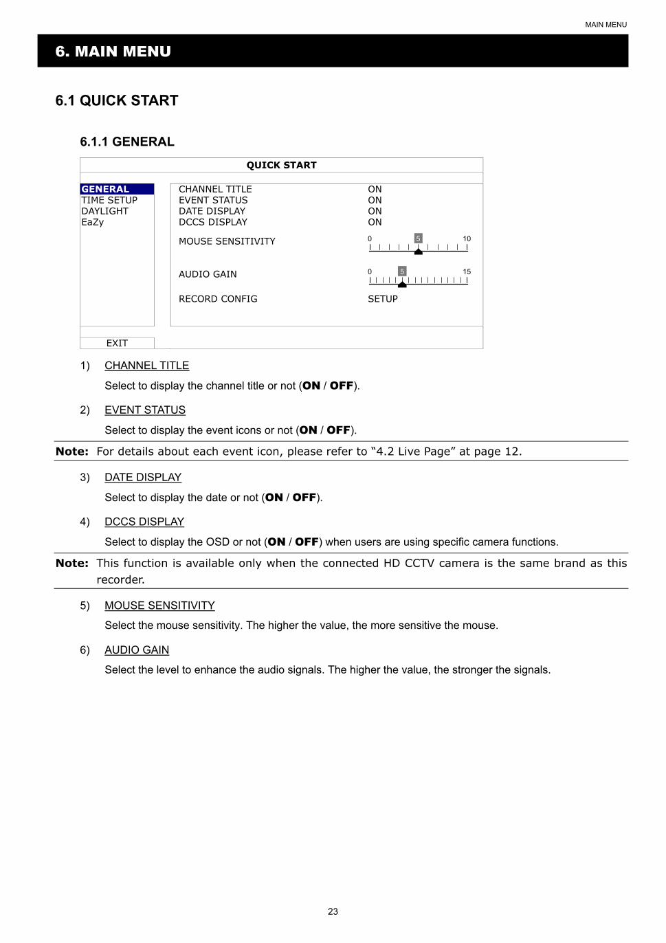
6.1.1 GENERAL
QUICK START
GENERAL CHANNEL TITLE ON TIME SETUP EVENT STATUS ON DAYLIGHT DATE DISPLAY ON EaZy DCCS DISPLAY ON
MOUSE SENSITIVITY 0 5 10
AUDIO GAIN 0 5 15
RECORD CONFIG SETUP
EXIT
1) CHANNEL TITLE
Select to display the channel title or not (ON / OFF).
2) EVENT STATUS
Select to display the event icons or not (ON / OFF).
Note: For details about each event icon, please refer to “4.2 Live Page” at page 12.
3) DATE DISPLAY
Select to display the date or not (ON / OFF).
4) DCCS DISPLAY
Select to display the OSD or not (ON / OFF) when users are using specific camera functions.
Note: This function is available only when the connected HD CCTV camera is the same brand as this recorder.
5) MOUSE SENSITIVITY
Select the mouse sensitivity. The higher the value, the more sensitive the mouse.
6) AUDIO GAIN
Select the level to enhance the audio signals. The higher the value, the stronger the signals.
MAIN MENU
24
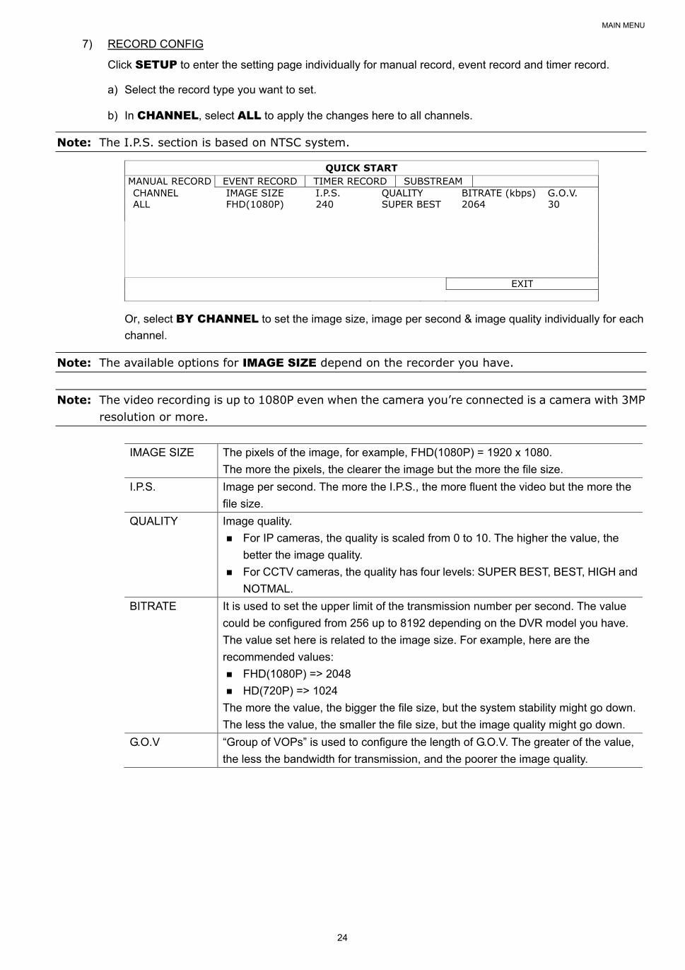
7) RECORD CONFIG
Click SETUP to enter the setting page individually for manual record, event record and timer record.
a) Select the record type you want to set.
b) In CHANNEL, select ALL to apply the changes here to all channels.
Note: The I.P.S. section is based on NTSC system.
QUICK START MANUAL RECORD EVENT RECORD TIMER RECORD SUBSTREAM CHANNEL IMAGE SIZE I.P.S. QUALITY BITRATE (kbps) G.O.V. ALL FHD(1080P) 240 SUPER BEST 2064 30
EXIT
Or, select BY CHANNEL to set the image size, image per second & image quality individually for each
channel.
Note: The available options for IMAGE SIZE depend on the recorder you have.
Note: The video recording is up to 1080P even when the camera you’re connected is a camera with 3MP resolution or more.
IMAGE SIZE The pixels of the image, for example, FHD(1080P) = 1920 x 1080.
The more the pixels, the clearer the image but the more the file size.
I.P.S. Image per second. The more the I.P.S., the more fluent the video but the more the
file size.
QUALITY Image quality.
For IP cameras, the quality is scaled from 0 to 10. The higher the value, the
better the image quality.
For CCTV cameras, the quality has four levels: SUPER BEST, BEST, HIGH and
NOTMAL.
BITRATE It is used to set the upper limit of the transmission number per second. The value
could be configured from 256 up to 8192 depending on the DVR model you have.
The value set here is related to the image size. For example, here are the
recommended values:
FHD(1080P) => 2048
HD(720P) => 1024
The more the value, the bigger the file size, but the system stability might go down.
The less the value, the smaller the file size, but the image quality might go down.
G.O.V “Group of VOPs” is used to configure the length of G.O.V. The greater of the value,
the less the bandwidth for transmission, and the poorer the image quality.
MAIN MENU
25
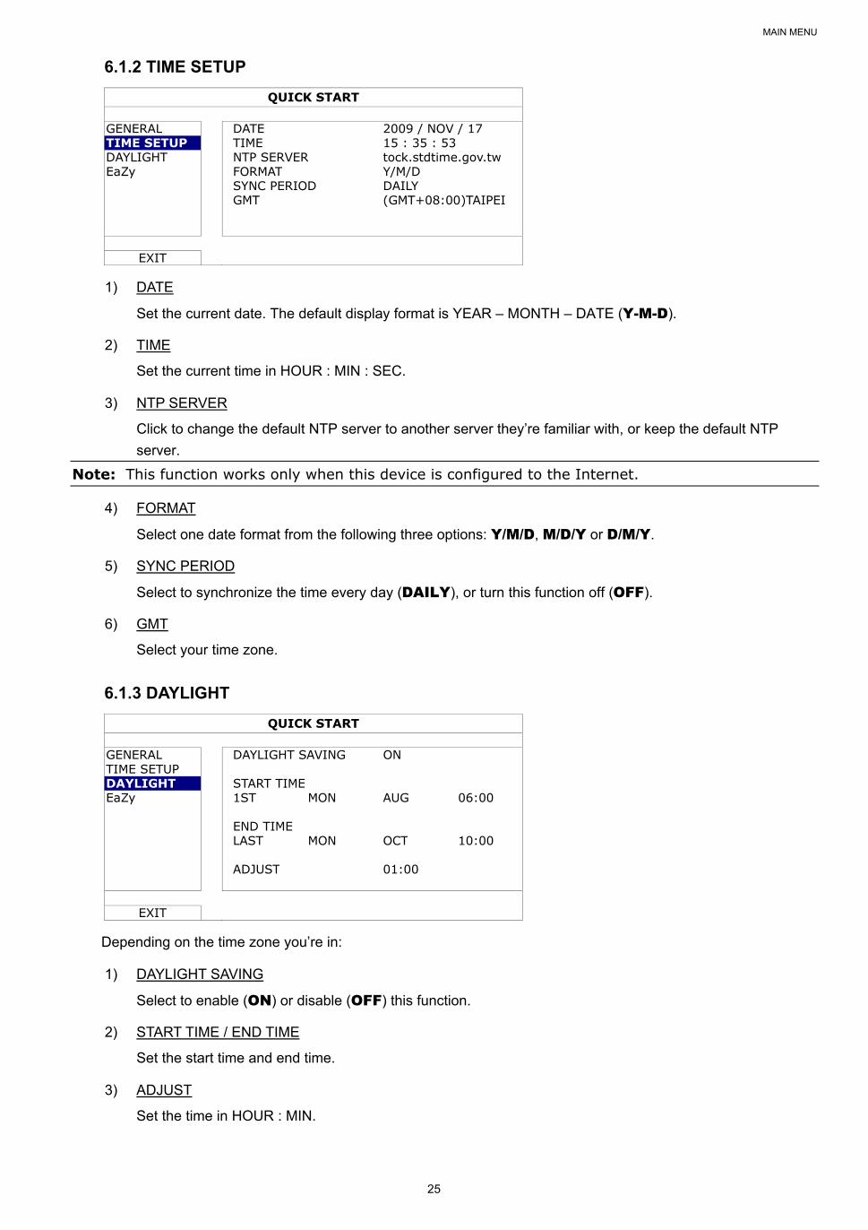
6.1.2 TIME SETUP
QUICK START
GENERAL DATE 2009 / NOV / 17 TIME SETUP TIME 15 : 35 : 53 DAYLIGHT NTP SERVER tock.stdtime.gov.tw EaZy FORMAT Y/M/D SYNC PERIOD DAILY GMT (GMT+08:00)TAIPEI
EXIT
1) DATE
Set the current date. The default display format is YEAR – MONTH – DATE (Y-M-D).
2) TIME
Set the current time in HOUR : MIN : SEC.
3) NTP SERVER
Click to change the default NTP server to another server they’re familiar with, or keep the default NTP
server.
Note: This function works only when this device is configured to the Internet.
4) FORMAT
Select one date format from the following three options: Y/M/D, M/D/Y or D/M/Y.
5) SYNC PERIOD
Select to synchronize the time every day (DAILY), or turn this function off (OFF).
6) GMT
Select your time zone.
6.1.3 DAYLIGHT
QUICK START
GENERAL DAYLIGHT SAVING ON TIME SETUP DAYLIGHT START TIME EaZy 1ST MON AUG 06:00 END TIME LAST MON OCT 10:00 ADJUST 01:00
EXIT
Depending on the time zone you’re in:
1) DAYLIGHT SAVING
Select to enable (ON) or disable (OFF) this function.
2) START TIME / END TIME
Set the start time and end time.
3) ADJUST
Set the time in HOUR : MIN.
MAIN MENU
26
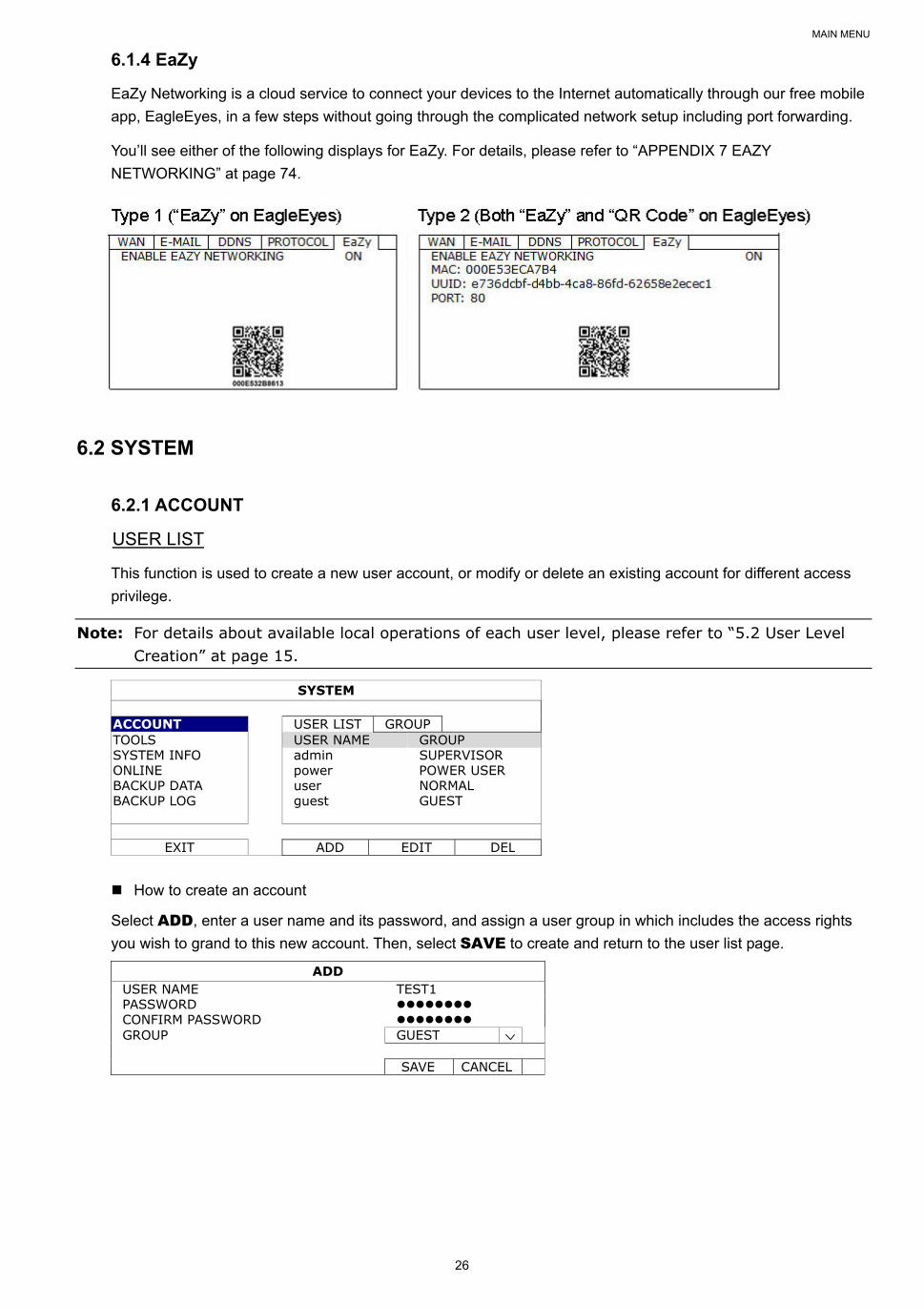
6.1.4 EaZy
EaZy Networking is a cloud service to connect your devices to the Internet automatically through our free mobile
app, EagleEyes, in a few steps without going through the complicated network setup including port forwarding.
You’ll see either of the following displays for EaZy. For details, please refer to “APPENDIX 7 EAZY
NETWORKING” at page 74.
6.2 SYSTEM
6.2.1 ACCOUNT
USER LIST
This function is used to create a new user account, or modify or delete an existing account for different access
privilege.
Note: For details about available local operations of each user level, please refer to “5.2 User Level Creation” at page 15.
SYSTEM
ACCOUNT USER LIST GROUP TOOLS USER NAME GROUP SYSTEM INFO admin SUPERVISOR ONLINE power POWER USER BACKUP DATA user NORMAL BACKUP LOG guest GUEST
EXIT ADD EDIT DEL
How to create an account
Select ADD, enter a user name and its password, and assign a user group in which includes the access rights
you wish to grand to this new account. Then, select SAVE to create and return to the user list page.
ADD USER NAME TEST1 PASSWORD CONFIRM PASSWORD GROUP GUEST
SAVE CANCEL
MAIN MENU
27
GROUP
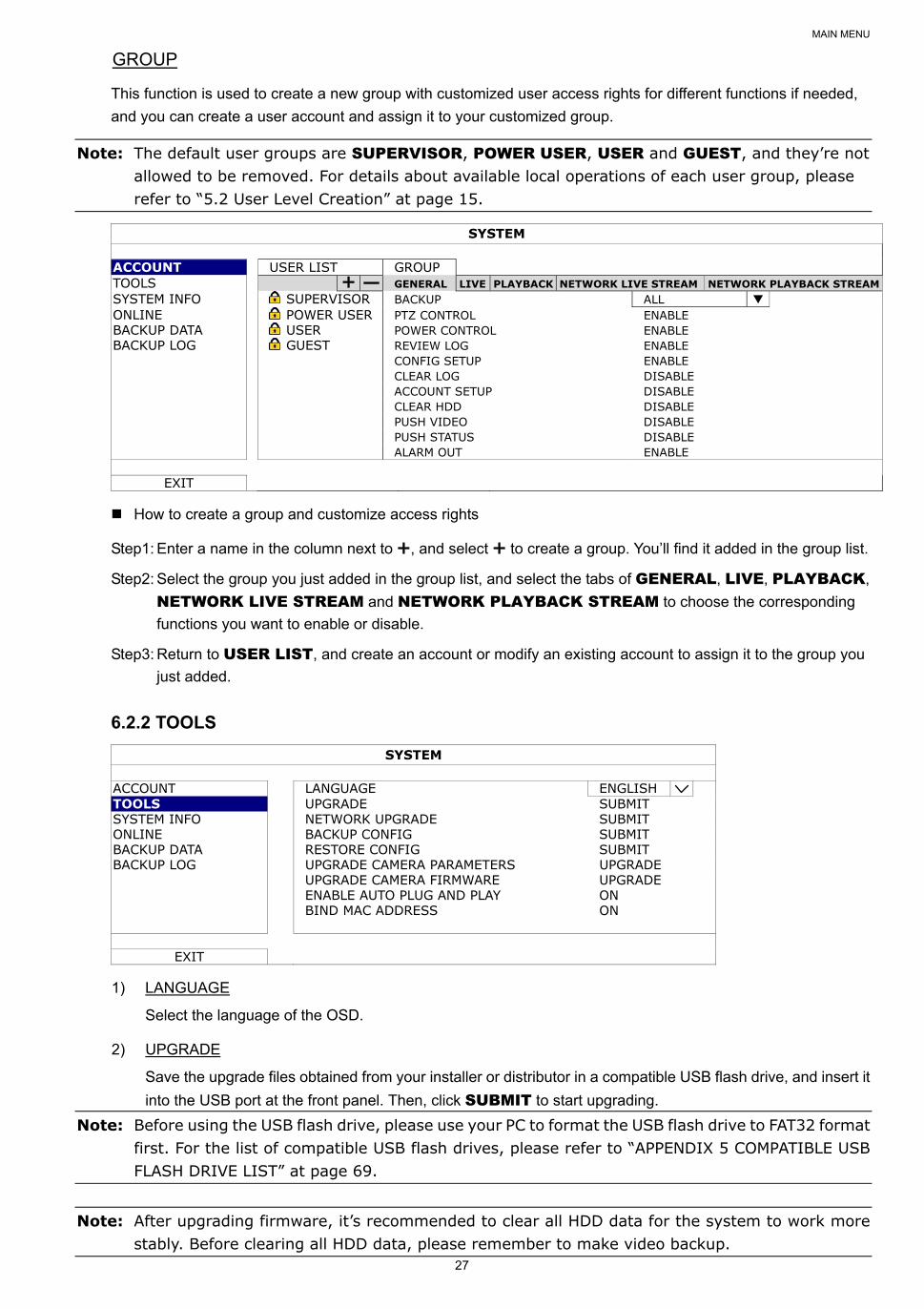
This function is used to create a new group with customized user access rights for different functions if needed,
and you can create a user account and assign it to your customized group.
Note: The default user groups are SUPERVISOR, POWER USER, USER and GUEST, and they’re not allowed to be removed. For details about available local operations of each user group, please refer to “5.2 User Level Creation” at page 15.
SYSTEM
ACCOUNT USER LIST GROUP TOOLS GENERAL LIVE PLAYBACK NETWORK LIVE STREAM NETWORK PLAYBACK STREAM SYSTEM INFO SUPERVISOR BACKUP ALL ONLINE POWER USER PTZ CONTROL ENABLE BACKUP DATA USER POWER CONTROL ENABLE BACKUP LOG GUEST REVIEW LOG ENABLE CONFIG SETUP ENABLE CLEAR LOG DISABLE ACCOUNT SETUP DISABLE CLEAR HDD DISABLE PUSH VIDEO DISABLE PUSH STATUS DISABLE ALARM OUT ENABLE
EXIT
How to create a group and customize access rights
Step1: Enter a name in the column next to , and select to create a group. You’ll find it added in the group list.
Step2: Select the group you just added in the group list, and select the tabs of GENERAL, LIVE, PLAYBACK,
NETWORK LIVE STREAM and NETWORK PLAYBACK STREAM to choose the corresponding
functions you want to enable or disable.
Step3: Return to USER LIST, and create an account or modify an existing account to assign it to the group you
just added.
6.2.2 TOOLS
SYSTEM
ACCOUNT LANGUAGE ENGLISH TOOLS UPGRADE SUBMIT SYSTEM INFO NETWORK UPGRADE SUBMIT ONLINE BACKUP CONFIG SUBMIT BACKUP DATA RESTORE CONFIG SUBMIT BACKUP LOG UPGRADE CAMERA PARAMETERS UPGRADE UPGRADE CAMERA FIRMWARE UPGRADE ENABLE AUTO PLUG AND PLAY ON BIND MAC ADDRESS ON
EXIT
1) LANGUAGE
Select the language of the OSD.
2) UPGRADE
Save the upgrade files obtained from your installer or distributor in a compatible USB flash drive, and insert it
into the USB port at the front panel. Then, click SUBMIT to start upgrading.
Note: Before using the USB flash drive, please use your PC to format the USB flash drive to FAT32 format first. For the list of compatible USB flash drives, please refer to “APPENDIX 5 COMPATIBLE USB FLASH DRIVE LIST” at page 69.
Note: After upgrading firmware, it’s recommended to clear all HDD data for the system to work more stably. Before clearing all HDD data, please remember to make video backup.
MAIN MENU
28
3) NETWORK UPGRADE
Click SUBMIT for perform system upgrade via Internet.
Note: This function requires Internet access. Please make sure this recorder is connected to Internet before using this function.
4) BACKUP CONFIG / RESTORE CONFIG
To save the DVR current configurations for later use, such as restoring after DVR upgrade or applying to
another DVR, insert a compatible USB flash drive into the USB port, and select SUBMIT in BACKUP CONFIG to copy the current DVR configurations to a file “System.bin” and save to your USB flash drive.
To restore the DVR configurations, insert the USB flash drive including “System.bin” to the USB port, and
select SUBMIT in RESTORE CONFIG.
5) UPGRADE CAMERA PARAMETERS / UPGRADE CAMERA FIRMWARE
This function is used only to upgrade the parameters / firmware of our brand’s HD CCTV camera when
necessary.
Get the upgrade file from our installer or distributor and save it to a USB flash drive. Then, select
UPGRADE to start the upgrade.
6) ENABLE AUTO PLUG AND PLAY
Switch to ON allow the camera to be detected and configured automatically when it’s connected to this
device.
Note: This function is available only when the brand of the cameras connected is the same as this device.
7) BIND MAC ADDRESS
This function is recommended to be used when your surveillance system is more than 256 cameras. It would
be helpful for the system to get the address of each connected camera quickly if the system accidentally
shuts down and needs to recover.
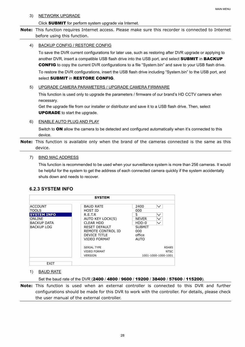
6.2.3 SYSTEM INFO
SYSTEM
ACCOUNT BAUD RATE 2400 TOOLS HOST ID 000 SYSTEM INFO R.E.T.R 5 ONLINE AUTO KEY LOCK(S) NEVER BACKUP DATA CLEAR HDD HDD-0 BACKUP LOG RESET DEFAULT SUBMIT REMOTE CONTROL ID 000 DEVICE TITLE office VIDEO FORMAT AUTO SERIAL TYPE RS485 VIDEO FORMAT NTSC VERSION 1001-1000-1000-1001
EXIT
1) BAUD RATE
Set the baud rate of the DVR (2400 / 4800 / 9600 / 19200 / 38400 / 57600 / 115200).
Note: This function is used when an external controller is connected to this DVR and further configurations should be made for this DVR to work with the controller. For details, please check the user manual of the external controller.
MAIN MENU
29
2) HOST ID
Set the ID of the DVR (000 ~ 254).
Note: This function is used when an external controller is connected to this DVR and further configurations should be made for this DVR to work with the controller. For details, please check the user manual of the external controller.
3) R.E.T.R (Remote Event Trigger Recording)
Select the timeout in minute after which the R.E.T.R. function will be activated (3 / 5 / 10 / 30).
4) AUTO KEY LOCK(S)
Set the time-out in second after which the key lock function is activated (NEVER / 30 / 60 / 120).
5) CLEAR HDD
Select the HDD you want to clear, and click YES to confirm or NO to cancel.
It’s recommended to clear all data in the hard disk when:
It’s the first time to use this DVR to ensure the recorded data are not mixed with other data previously saved in the
same hard disk.
The DVR firmware is upgraded for the system to work more stably. Before clearing all HDD data, please remember
to make video backup.
DVR date and time are changed accidentally when the recording function is activated. Otherwise, the recorded
data will be disordered and you will not be able to find the recorded file to backup by time search.
6) RESET DEFAULT
Click “SUBMIT” to reset all settings as default, and select YES to confirm or NO to cancel. The DVR will
reboot after reset.
7) REMOTE CONTROL ID
This function is available when users need to control two or more DVRs with one IR remote controller. The
ID set here is used to identify the DVR the remote controller is going to control. Please also read the user
manual of the IR remote controller for details.
8) DEVICE TITLE
Enter a title for this device.
9) VIDEO FORMAT
Allow the DVR to detect the video format automatically (AUTO), or choose NTSC or PAL manually.
10) SERIAL TYPE
Here shows the serial type of the DVR (RS-485).
11) VIDEO FORMAT
Here shows the information of the DVR video format (NTSC / PAL).
12) VERSION
Here shows the firmware version information.
MAIN MENU
30
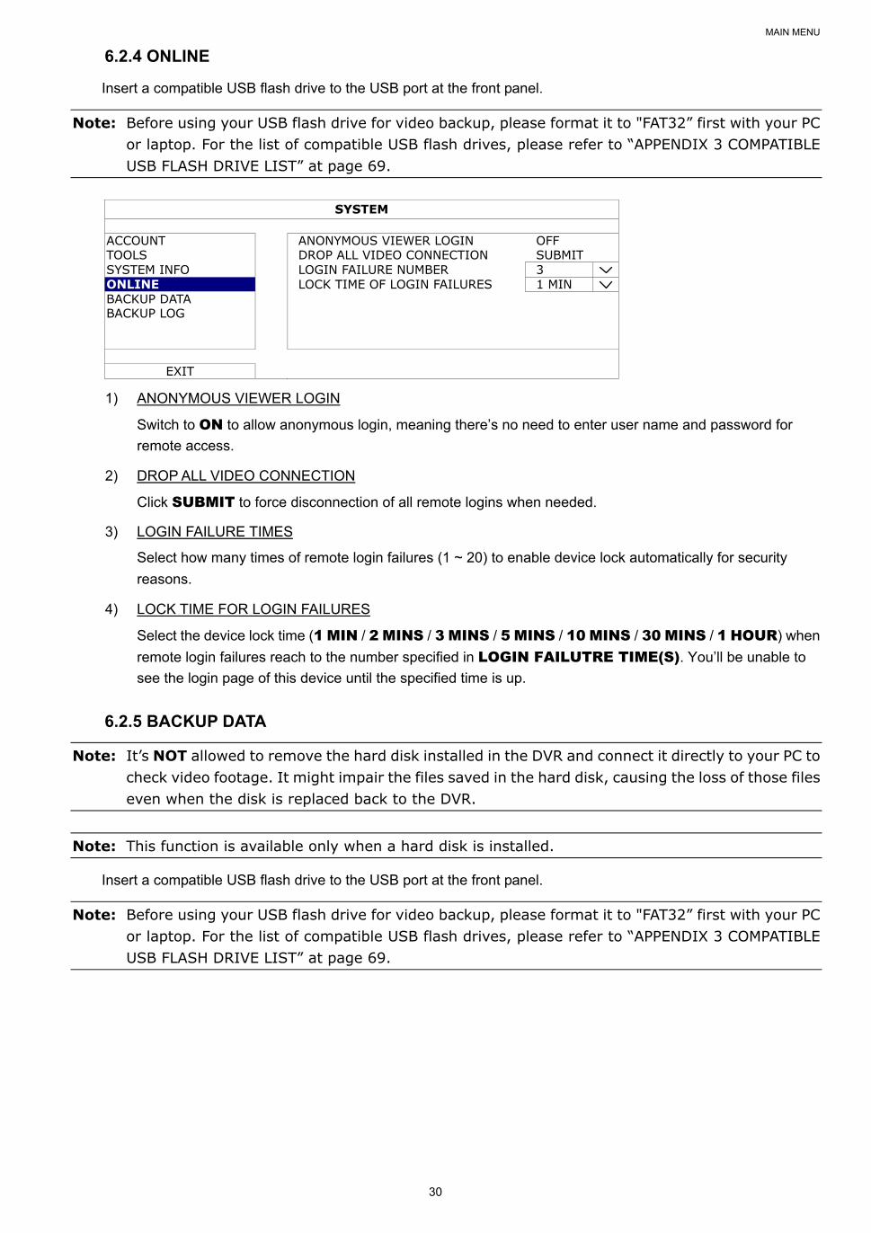
6.2.4 ONLINE
Insert a compatible USB flash drive to the USB port at the front panel.
Note: Before using your USB flash drive for video backup, please format it to "FAT32” first with your PC or laptop. For the list of compatible USB flash drives, please refer to “APPENDIX 3 COMPATIBLE USB FLASH DRIVE LIST” at page 69.
SYSTEM
ACCOUNT ANONYMOUS VIEWER LOGIN OFF TOOLS DROP ALL VIDEO CONNECTION SUBMIT SYSTEM INFO LOGIN FAILURE NUMBER 3 ONLINE LOCK TIME OF LOGIN FAILURES 1 MIN BACKUP DATA BACKUP LOG
EXIT
1) ANONYMOUS VIEWER LOGIN
Switch to ON to allow anonymous login, meaning there’s no need to enter user name and password for
remote access.
2) DROP ALL VIDEO CONNECTION
Click SUBMIT to force disconnection of all remote logins when needed.
3) LOGIN FAILURE TIMES
Select how many times of remote login failures (1 ~ 20) to enable device lock automatically for security
reasons.
4) LOCK TIME FOR LOGIN FAILURES
Select the device lock time (1 MIN / 2 MINS / 3 MINS / 5 MINS / 10 MINS / 30 MINS / 1 HOUR) when
remote login failures reach to the number specified in LOGIN FAILUTRE TIME(S). You’ll be unable to
see the login page of this device until the specified time is up.
6.2.5 BACKUP DATA
Note: It’s NOT allowed to remove the hard disk installed in the DVR and connect it directly to your PC to check video footage. It might impair the files saved in the hard disk, causing the loss of those files even when the disk is replaced back to the DVR.
Note: This function is available only when a hard disk is installed.
Insert a compatible USB flash drive to the USB port at the front panel.
Note: Before using your USB flash drive for video backup, please format it to "FAT32” first with your PC or laptop. For the list of compatible USB flash drives, please refer to “APPENDIX 3 COMPATIBLE USB FLASH DRIVE LIST” at page 69.
MAIN MENU
31
SYSTEM
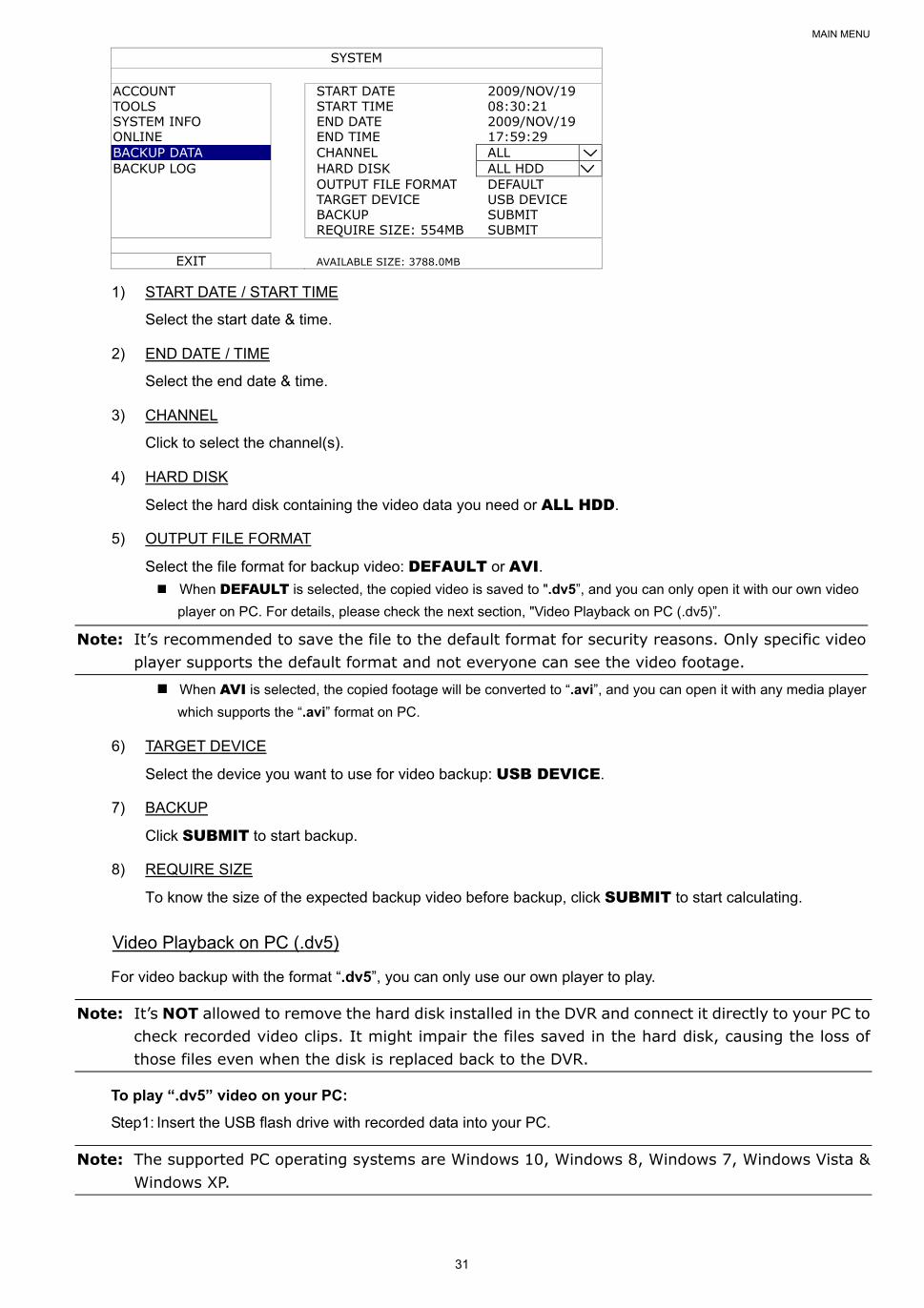
ACCOUNT START DATE 2009/NOV/19 TOOLS START TIME 08:30:21 SYSTEM INFO END DATE 2009/NOV/19 ONLINE END TIME 17:59:29 BACKUP DATA CHANNEL ALL BACKUP LOG HARD DISK ALL HDD OUTPUT FILE FORMAT DEFAULT TARGET DEVICE USB DEVICE BACKUP SUBMIT REQUIRE SIZE: 554MB SUBMIT
EXIT AVAILABLE SIZE: 3788.0MB
1) START DATE / START TIME
Select the start date & time.
2) END DATE / TIME
Select the end date & time.
3) CHANNEL
Click to select the channel(s).
4) HARD DISK
Select the hard disk containing the video data you need or ALL HDD.
5) OUTPUT FILE FORMAT
Select the file format for backup video: DEFAULT or AVI. When DEFAULT is selected, the copied video is saved to ".dv5”, and you can only open it with our own video
player on PC. For details, please check the next section, "Video Playback on PC (.dv5)”.
Note: It’s recommended to save the file to the default format for security reasons. Only specific video player supports the default format and not everyone can see the video footage.
When AVI is selected, the copied footage will be converted to “.avi”, and you can open it with any media player
which supports the “.avi” format on PC.
6) TARGET DEVICE
Select the device you want to use for video backup: USB DEVICE.
7) BACKUP
Click SUBMIT to start backup.
8) REQUIRE SIZE
To know the size of the expected backup video before backup, click SUBMIT to start calculating.
Video Playback on PC (.dv5)
For video backup with the format “.dv5”, you can only use our own player to play.
Note: It’s NOT allowed to remove the hard disk installed in the DVR and connect it directly to your PC to check recorded video clips. It might impair the files saved in the hard disk, causing the loss of those files even when the disk is replaced back to the DVR.
To play “.dv5” video on your PC:
Step1: Insert the USB flash drive with recorded data into your PC.
Note: The supported PC operating systems are Windows 10, Windows 8, Windows 7, Windows Vista & Windows XP.
MAIN MENU
32
Step2: Find the program “PLAYER.EXE” in the USB flash drive, and double-click it to install.
Note: “PLAYER.EXE” can also be downloaded from www.surveillance-download.com/user/z2116.swf.
Step3: Run the program, VideoPlayer, and browse to where you save the recorded data.
Step4: Select the file you want to start video playback.
Convert the file format to AVI:
To convert the video file format to AVI, click AVI from the playback panel to start file conversion.
Note: The recorded audio (if any) will be removed when the file format is converted to AVI.
Note: If the footage includes data for multiple channels, click to a specific channel for this function to work properly.
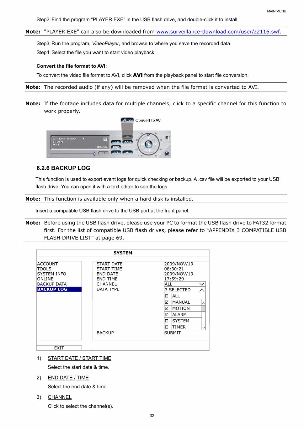
6.2.6 BACKUP LOG
This function is used to export event logs for quick checking or backup. A .csv file will be exported to your USB
flash drive. You can open it with a text editor to see the logs.
Note: This function is available only when a hard disk is installed.
Insert a compatible USB flash drive to the USB port at the front panel.
Note: Before using the USB flash drive, please use your PC to format the USB flash drive to FAT32 format first. For the list of compatible USB flash drives, please refer to “APPENDIX 3 COMPATIBLE USB FLASH DRIVE LIST” at page 69.
SYSTEM
ACCOUNT START DATE 2009/NOV/19 TOOLS START TIME 08:30:21 SYSTEM INFO END DATE 2009/NOV/19 ONLINE END TIME 17:59:29 BACKUP DATA CHANNEL ALL BACKUP LOG DATA TYPE 3 SELECTED ALL MANUAL MOTION ALARM SYSTEM TIMER BACKUP SUBMIT
EXIT
1) START DATE / START TIME
Select the start date & time.
2) END DATE / TIME
Select the end date & time.
3) CHANNEL
Click to select the channel(s).
MAIN MENU
33
4) DATA TYPE
Click “SETUP” to select the event type you want: MANUAL / MOTION / ALARM / SYSTEM / TIMER /
HUMAN DETECTION / INFLOW / OUTFLOW / VIRTUAL FENCE / ONEWAY / SENCE CHANGE,
or select ALL to choose all event types.
Note: The event types available depend on the model you have.
5) BACKUP
Click SUBMIT to start backup. You’ll see a log file (.csv) in the flash drive. You may open it with any txt
editor, such as NotePad.
6.3 EVENT INFORMATION
6.3.1 QUICK SEARCH
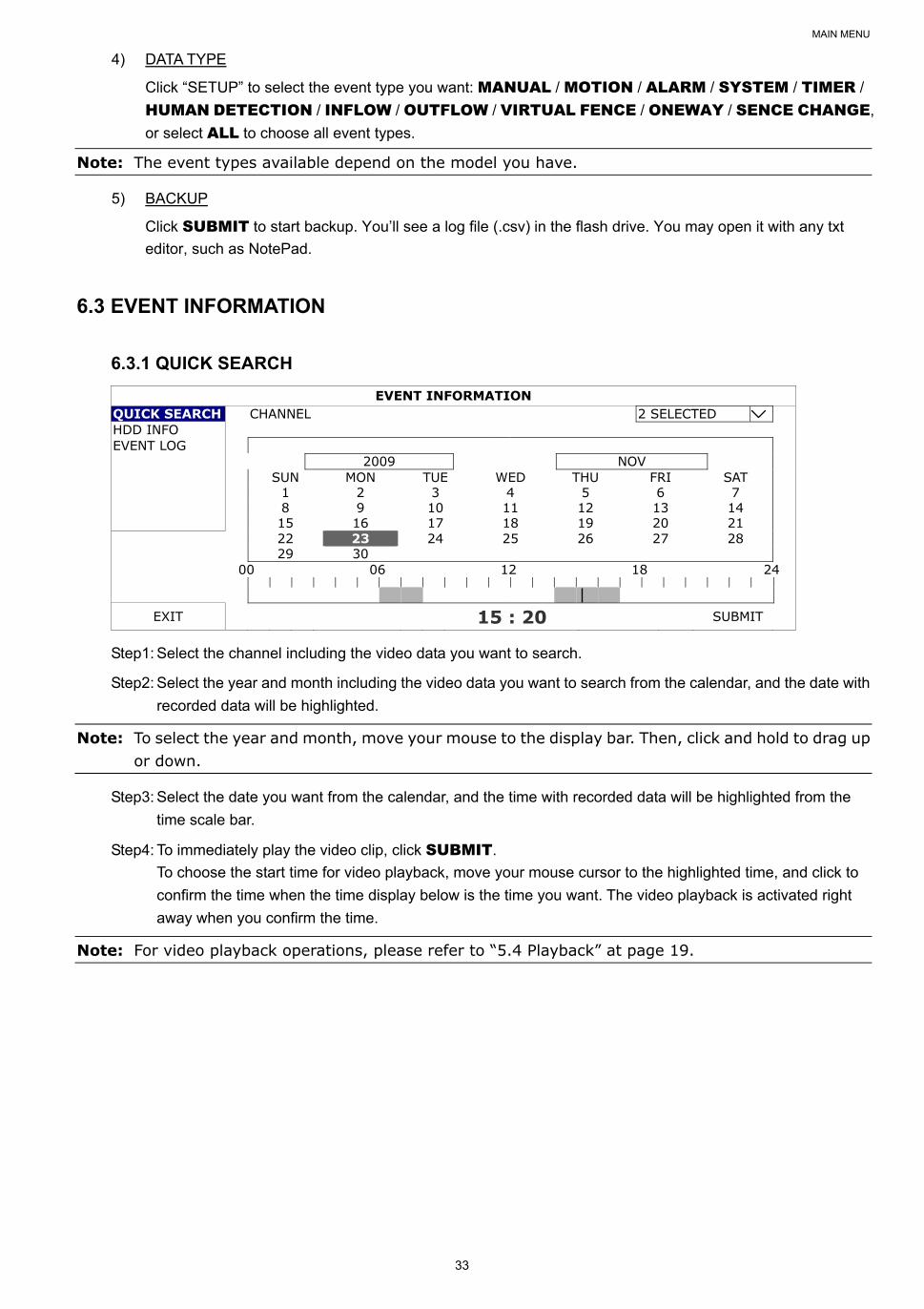
EVENT INFORMATION QUICK SEARCH CHANNEL 2 SELECTED HDD INFO EVENT LOG 2009 NOV SUN MON TUE WED THU FRI SAT 1 2 3 4 5 6 7 8 9 10 11 12 13 14 15 16 17 18 19 20 21
22 23 24 25 26 27 28 29 30 00 06 12 18 24
EXIT 15 : 20 SUBMIT
Step1: Select the channel including the video data you want to search.
Step2: Select the year and month including the video data you want to search from the calendar, and the date with
recorded data will be highlighted.
Note: To select the year and month, move your mouse to the display bar. Then, click and hold to drag up or down.
Step3: Select the date you want from the calendar, and the time with recorded data will be highlighted from the
time scale bar.
Step4: To immediately play the video clip, click SUBMIT.
To choose the start time for video playback, move your mouse cursor to the highlighted time, and click to
confirm the time when the time display below is the time you want. The video playback is activated right
away when you confirm the time.
Note: For video playback operations, please refer to “5.4 Playback” at page 19.
MAIN MENU
34
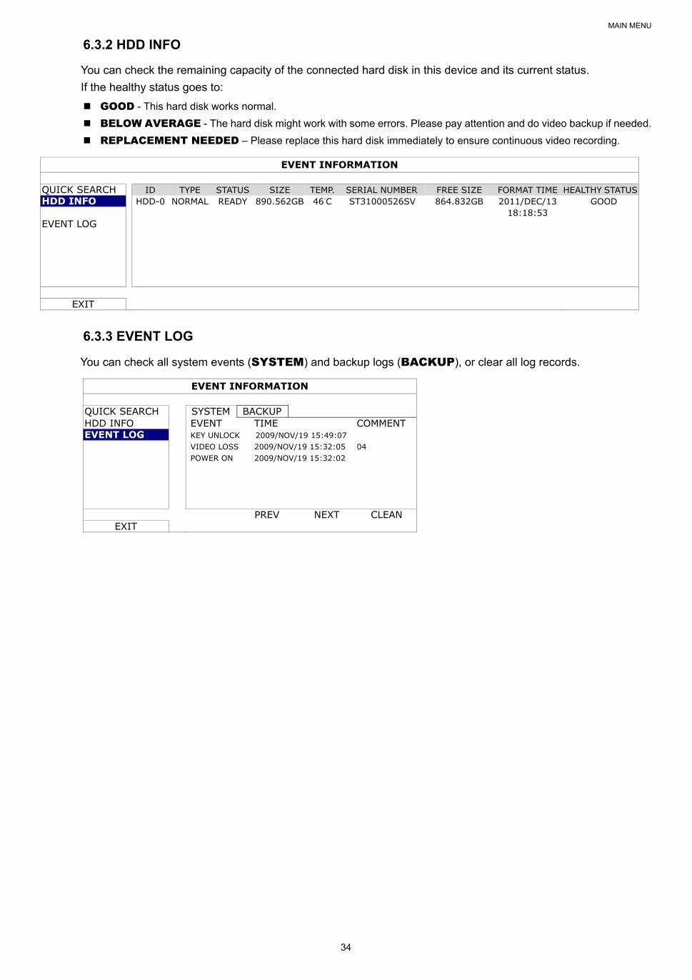
6.3.2 HDD INFO
You can check the remaining capacity of the connected hard disk in this device and its current status.
If the healthy status goes to:
GOOD - This hard disk works normal.
BELOW AVERAGE - The hard disk might work with some errors. Please pay attention and do video backup if needed.
REPLACEMENT NEEDED – Please replace this hard disk immediately to ensure continuous video recording.
EVENT INFORMATION
QUICK SEARCH ID TYPE STATUS SIZE TEMP. SERIAL NUMBER FREE SIZE FORMAT TIME HEALTHY STATUS HDD INFO HDD-0 NORMAL READY 890.562GB 46°C ST31000526SV 864.832GB 2011/DEC/13
18:18:53 GOOD
EVENT LOG
EXIT
6.3.3 EVENT LOG
You can check all system events (SYSTEM) and backup logs (BACKUP), or clear all log records.
EVENT INFORMATION
QUICK SEARCH SYSTEM BACKUP HDD INFO EVENT TIME COMMENT EVENT LOG KEY UNLOCK 2009/NOV/19 15:49:07
VIDEO LOSS 2009/NOV/19 15:32:05 04 POWER ON 2009/NOV/19 15:32:02
PREV NEXT CLEAN EXIT
MAIN MENU
35
6.4 ADVANCED CONFIG
6.4.1 CAMERA
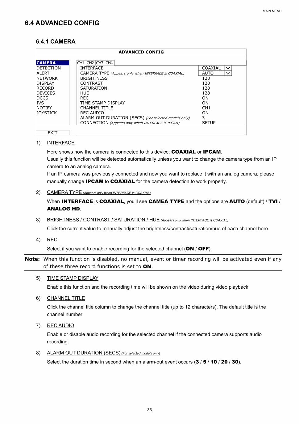
ADVANCED CONFIG
CAMERA CH1 CH2 CH3 CH4 DETECTION INTERFACE COAXIAL ALERT CAMERA TYPE (Appears only when INTERFACE is COAXIAL) AUTO NETWORK BRIGHTNESS 128 DISPLAY CONTRAST 128 RECORD SATURATION 128 DEVICES HUE 128 DCCS REC ON IVS TIME STAMP DISPLAY ON NOTIFY CHANNEL TITLE CH1 JOYSTICK REC AUDIO ON ALARM OUT DURATION (SECS) (For selected models only) 3 CONNECTION (Appears only when INTERFACE is IPCAM) SETUP
EXIT
1) INTERFACE
Here shows how the camera is connected to this device: COAXIAL or IPCAM.
Usually this function will be detected automatically unless you want to change the camera type from an IP
camera to an analog camera.
If an IP camera was previously connected and now you want to replace it with an analog camera, please
manually change IPCAM to COAXIAL for the camera detection to work properly.
2) CAMERA TYPE (Appears only when INTERFACE is COAXIAL)
When INTERFACE is COAXIAL, you’ll see CAMEA TYPE and the options are AUTO (default) / TVI / ANALOG HD.
3) BRIGHTNESS / CONTRAST / SATURATION / HUE (Appears only when INTERFACE is COAXIAL)
Click the current value to manually adjust the brightness/contrast/saturation/hue of each channel here.
4) REC
Select if you want to enable recording for the selected channel (ON / OFF).
Note: When this function is disabled, no manual, event or timer recording will be activated even if any of these three record functions is set to ON.
5) TIME STAMP DISPLAY
Enable this function and the recording time will be shown on the video during video playback.
6) CHANNEL TITLE
Click the channel title column to change the channel title (up to 12 characters). The default title is the
channel number.
7) REC AUDIO
Enable or disable audio recording for the selected channel if the connected camera supports audio
recording.
8) ALARM OUT DURATION (SECS) (For selected models only)
Select the duration time in second when an alarm-out event occurs (3 / 5 / 10 / 20 / 30).
MAIN MENU
36
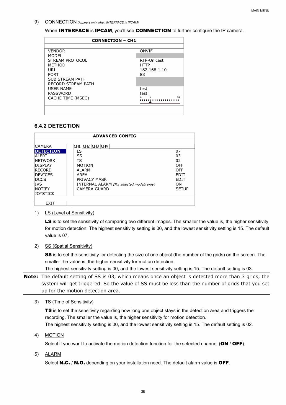
9) CONNECTION (Appears only when INTERFACE is IPCAM)
When INTERFACE is IPCAM, you’ll see CONNECTION to further configure the IP camera.
CONNECTION – CH1
VENDOR ONVIF MODEL STREAM PROTOCOL RTP-Unicast METHOD HTTP URI 182.168.1.10 PORT 88 SUB STREAM PATH RECORD STREAM PATH USER NAME test PASSWORD test CACHE TIME (MSEC)
6.4.2 DETECTION
ADVANCED CONFIG
CAMERA CH1 CH2 CH3 CH4 DETECTION LS 07 ALERT SS 03 NETWORK TS 02 DISPLAY MOTION OFF RECORD ALARM OFF DEVICES AREA EDIT DCCS PRIVACY MASK EDIT IVS INTERNAL ALARM (For selected models only) ON NOTIFY CAMERA GUARD SETUP JOYSTICK
EXIT
1) LS (Level of Sensitivity)
LS is to set the sensitivity of comparing two different images. The smaller the value is, the higher sensitivity
for motion detection. The highest sensitivity setting is 00, and the lowest sensitivity setting is 15. The default
value is 07.
2) SS (Spatial Sensitivity)
SS is to set the sensitivity for detecting the size of one object (the number of the grids) on the screen. The
smaller the value is, the higher sensitivity for motion detection.
The highest sensitivity setting is 00, and the lowest sensitivity setting is 15. The default setting is 03.
Note: The default setting of SS is 03, which means once an object is detected more than 3 grids, the system will get triggered. So the value of SS must be less than the number of grids that you set up for the motion detection area.
3) TS (Time of Sensitivity)
TS is to set the sensitivity regarding how long one object stays in the detection area and triggers the
recording. The smaller the value is, the higher sensitivity for motion detection.
The highest sensitivity setting is 00, and the lowest sensitivity setting is 15. The default setting is 02.
4) MOTION
Select if you want to activate the motion detection function for the selected channel (ON / OFF).
5) ALARM
Select N.C. / N.O. depending on your installation need. The default alarm value is OFF.
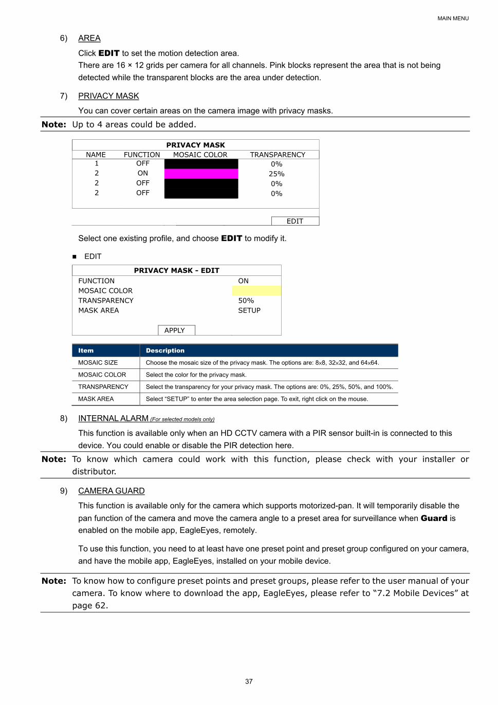
MAIN MENU
37
6) AREA
Click EDIT to set the motion detection area.
There are 16 × 12 grids per camera for all channels. Pink blocks represent the area that is not being
detected while the transparent blocks are the area under detection.
7) PRIVACY MASK
You can cover certain areas on the camera image with privacy masks.
Note: Up to 4 areas could be added.
PRIVACY MASK NAME FUNCTION MOSAIC COLOR TRANSPARENCY
1 OFF 0% 2 ON 25% 2 OFF 0% 2 OFF 0%
EDIT
Select one existing profile, and choose EDIT to modify it.
EDIT
PRIVACY MASK - EDIT FUNCTION ON MOSAIC COLOR TRANSPARENCY 50% MASK AREA SETUP APPLY
Item Description
MOSAIC SIZE Choose the mosaic size of the privacy mask. The options are: 8×8, 32×32, and 64×64.
MOSAIC COLOR Select the color for the privacy mask.
TRANSPARENCY Select the transparency for your privacy mask. The options are: 0%, 25%, 50%, and 100%.
MASK AREA Select “SETUP” to enter the area selection page. To exit, right click on the mouse.
8) INTERNAL ALARM (For selected models only)
This function is available only when an HD CCTV camera with a PIR sensor built-in is connected to this
device. You could enable or disable the PIR detection here.
Note: To know which camera could work with this function, please check with your installer or distributor.
9) CAMERA GUARD
This function is available only for the camera which supports motorized-pan. It will temporarily disable the
pan function of the camera and move the camera angle to a preset area for surveillance when Guard is
enabled on the mobile app, EagleEyes, remotely.
To use this function, you need to at least have one preset point and preset group configured on your camera,
and have the mobile app, EagleEyes, installed on your mobile device.
Note: To know how to configure preset points and preset groups, please refer to the user manual of your camera. To know where to download the app, EagleEyes, please refer to “7.2 Mobile Devices” at page 62.
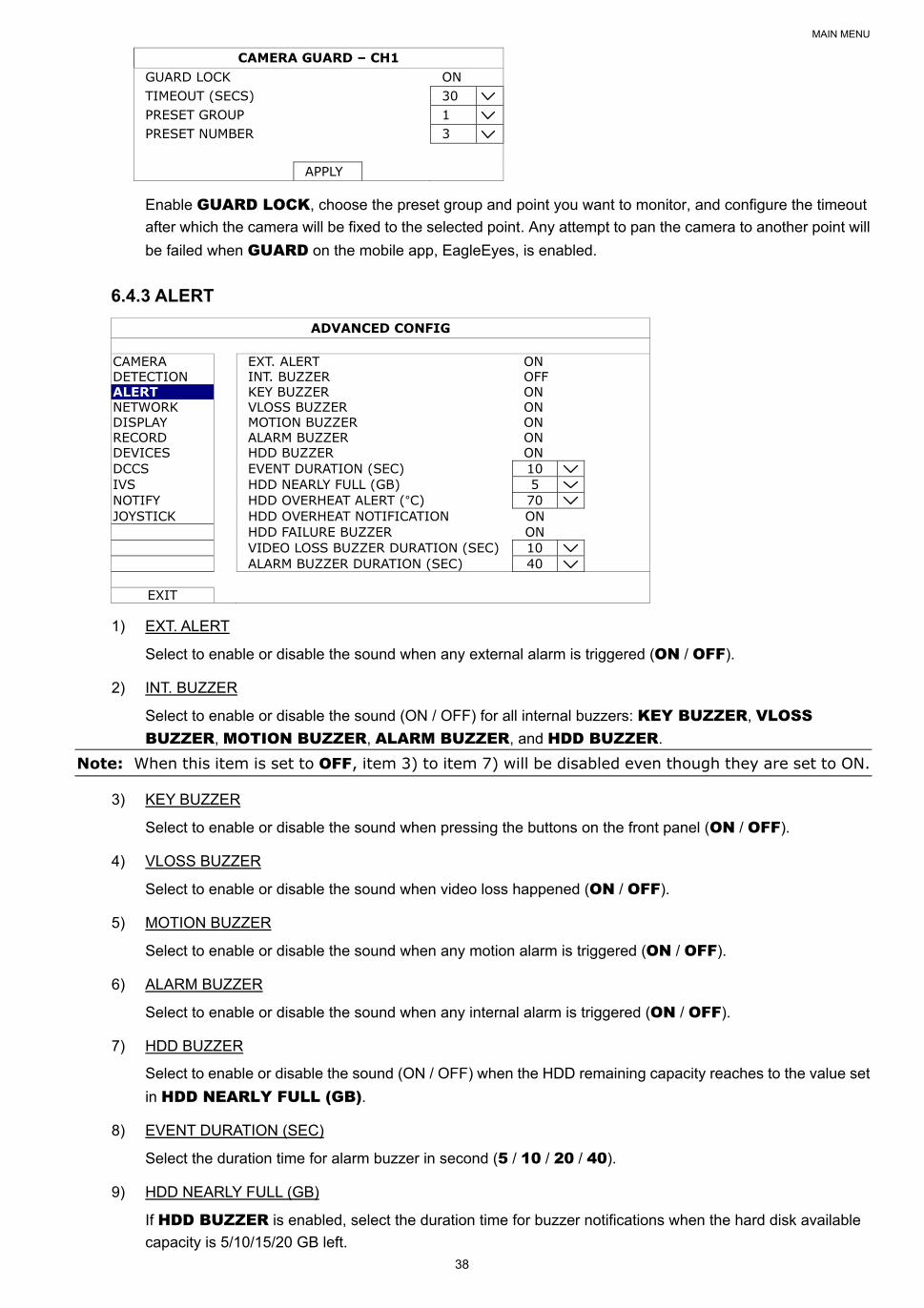
MAIN MENU
38
CAMERA GUARD – CH1 GUARD LOCK ON TIMEOUT (SECS) 30 PRESET GROUP 1 PRESET NUMBER 3 APPLY
Enable GUARD LOCK, choose the preset group and point you want to monitor, and configure the timeout
after which the camera will be fixed to the selected point. Any attempt to pan the camera to another point will
be failed when GUARD on the mobile app, EagleEyes, is enabled.
6.4.3 ALERT
ADVANCED CONFIG
CAMERA EXT. ALERT ON DETECTION INT. BUZZER OFF ALERT KEY BUZZER ON NETWORK VLOSS BUZZER ON DISPLAY MOTION BUZZER ON RECORD ALARM BUZZER ON DEVICES HDD BUZZER ON DCCS EVENT DURATION (SEC) 10 IVS HDD NEARLY FULL (GB) 5 NOTIFY HDD OVERHEAT ALERT (°C) 70 JOYSTICK HDD OVERHEAT NOTIFICATION ON HDD FAILURE BUZZER ON VIDEO LOSS BUZZER DURATION (SEC) 10 ALARM BUZZER DURATION (SEC) 40
EXIT
1) EXT. ALERT
Select to enable or disable the sound when any external alarm is triggered (ON / OFF).
2) INT. BUZZER
Select to enable or disable the sound (ON / OFF) for all internal buzzers: KEY BUZZER, VLOSS BUZZER, MOTION BUZZER, ALARM BUZZER, and HDD BUZZER.
Note: When this item is set to OFF, item 3) to item 7) will be disabled even though they are set to ON.
3) KEY BUZZER
Select to enable or disable the sound when pressing the buttons on the front panel (ON / OFF).
4) VLOSS BUZZER
Select to enable or disable the sound when video loss happened (ON / OFF).
5) MOTION BUZZER
Select to enable or disable the sound when any motion alarm is triggered (ON / OFF).
6) ALARM BUZZER
Select to enable or disable the sound when any internal alarm is triggered (ON / OFF).
7) HDD BUZZER
Select to enable or disable the sound (ON / OFF) when the HDD remaining capacity reaches to the value set
in HDD NEARLY FULL (GB).
8) EVENT DURATION (SEC)
Select the duration time for alarm buzzer in second (5 / 10 / 20 / 40).
9) HDD NEARLY FULL (GB)
If HDD BUZZER is enabled, select the duration time for buzzer notifications when the hard disk available
capacity is 5/10/15/20 GB left.
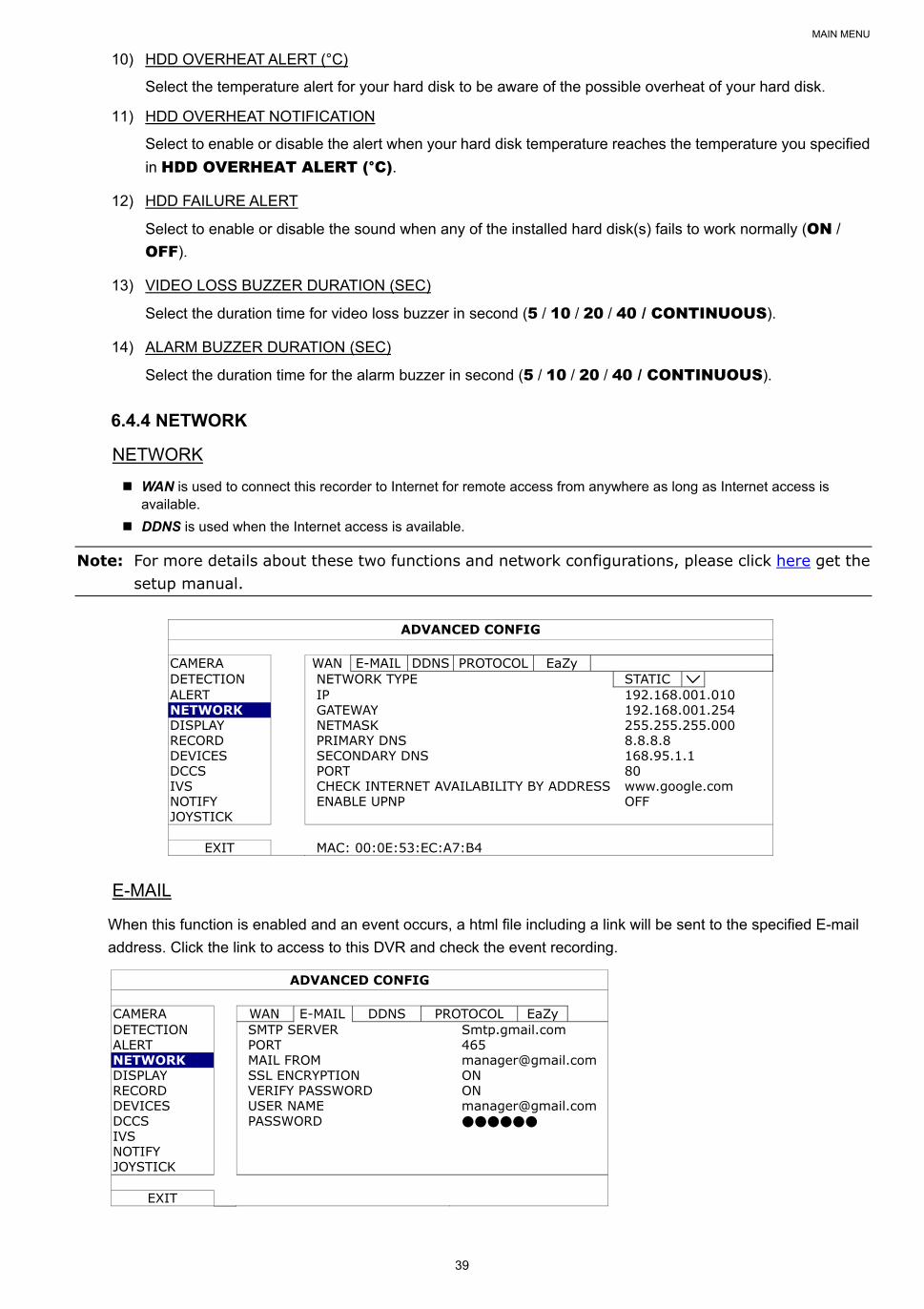
MAIN MENU
39
10) HDD OVERHEAT ALERT (°C)
Select the temperature alert for your hard disk to be aware of the possible overheat of your hard disk.
11) HDD OVERHEAT NOTIFICATION
Select to enable or disable the alert when your hard disk temperature reaches the temperature you specified
in HDD OVERHEAT ALERT (°C).
12) HDD FAILURE ALERT
Select to enable or disable the sound when any of the installed hard disk(s) fails to work normally (ON /
OFF).
13) VIDEO LOSS BUZZER DURATION (SEC)
Select the duration time for video loss buzzer in second (5 / 10 / 20 / 40 / CONTINUOUS).
14) ALARM BUZZER DURATION (SEC)
Select the duration time for the alarm buzzer in second (5 / 10 / 20 / 40 / CONTINUOUS).
6.4.4 NETWORK
NETWORK
WAN is used to connect this recorder to Internet for remote access from anywhere as long as Internet access is available.
DDNS is used when the Internet access is available.
Note: For more details about these two functions and network configurations, please click here get the setup manual.
ADVANCED CONFIG
CAMERA WAN E-MAIL DDNS PROTOCOL EaZy DETECTION NETWORK TYPE STATIC ALERT IP 192.168.001.010 NETWORK GATEWAY 192.168.001.254 DISPLAY NETMASK 255.255.255.000 RECORD PRIMARY DNS 8.8.8.8 DEVICES SECONDARY DNS 168.95.1.1 DCCS PORT 80 IVS CHECK INTERNET AVAILABILITY BY ADDRESS www.google.com NOTIFY ENABLE UPNP OFF JOYSTICK
EXIT MAC: 00:0E:53:EC:A7:B4
When this function is enabled and an event occurs, a html file including a link will be sent to the specified E-mail
address. Click the link to access to this DVR and check the event recording.
ADVANCED CONFIG
CAMERA WAN E-MAIL DDNS PROTOCOL EaZy DETECTION SMTP SERVER Smtp.gmail.com ALERT PORT 465 NETWORK MAIL FROM [email protected] DISPLAY SSL ENCRYPTION ON RECORD VERIFY PASSWORD ON DEVICES USER NAME [email protected] DCCS PASSWORD IVS NOTIFY JOYSTICK
EXIT
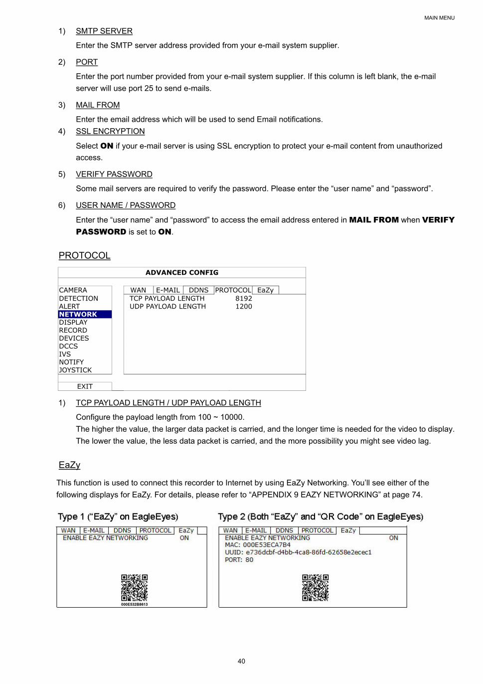
MAIN MENU
40
1) SMTP SERVER
Enter the SMTP server address provided from your e-mail system supplier.
2) PORT
Enter the port number provided from your e-mail system supplier. If this column is left blank, the e-mail
server will use port 25 to send e-mails.
3) MAIL FROM
Enter the email address which will be used to send Email notifications.
4) SSL ENCRYPTION
Select ON if your e-mail server is using SSL encryption to protect your e-mail content from unauthorized
access.
5) VERIFY PASSWORD
Some mail servers are required to verify the password. Please enter the “user name” and “password”.
6) USER NAME / PASSWORD
Enter the “user name” and “password” to access the email address entered in MAIL FROM when VERIFY PASSWORD is set to ON.
PROTOCOL
ADVANCED CONFIG
CAMERA WAN E-MAIL DDNS PROTOCOL EaZy DETECTION TCP PAYLOAD LENGTH 8192 ALERT UDP PAYLOAD LENGTH 1200 NETWORK DISPLAY RECORD DEVICES DCCS IVS NOTIFY JOYSTICK
EXIT
1) TCP PAYLOAD LENGTH / UDP PAYLOAD LENGTH
Configure the payload length from 100 ~ 10000.
The higher the value, the larger data packet is carried, and the longer time is needed for the video to display.
The lower the value, the less data packet is carried, and the more possibility you might see video lag.
EaZy
This function is used to connect this recorder to Internet by using EaZy Networking. You’ll see either of the
following displays for EaZy. For details, please refer to “APPENDIX 9 EAZY NETWORKING” at page 74.
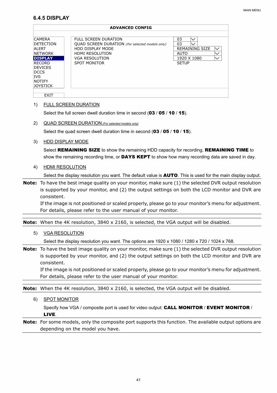
MAIN MENU
41
6.4.5 DISPLAY
ADVANCED CONFIG
CAMERA FULL SCREEN DURATION 03 DETECTION QUAD SCREEN DURATION (For selected models only) 03 ALERT HDD DISPLAY MODE REMAINING SIZE NETWORK HDMI RESOLUTION AUTO DISPLAY VGA RESOLUTION 1920 X 1080 RECORD SPOT MONITOR SETUP DEVICES DCCS IVS NOTIFY JOYSTICK
EXIT
1) FULL SCREEN DURATION
Select the full screen dwell duration time in second (03 / 05 / 10 / 15).
2) QUAD SCREEN DURATION (For selected models only)
Select the quad screen dwell duration time in second (03 / 05 / 10 / 15).
3) HDD DISPLAY MODE
Select REMAINING SIZE to show the remaining HDD capacity for recording, REMAINING TIME to
show the remaining recording time, or DAYS KEPT to show how many recording data are saved in day.
4) HDMI RESOLUTION
Select the display resolution you want. The default value is AUTO. This is used for the main display output.
Note: To have the best image quality on your monitor, make sure (1) the selected DVR output resolution is supported by your monitor, and (2) the output settings on both the LCD monitor and DVR are consistent. If the image is not positioned or scaled properly, please go to your monitor’s menu for adjustment. For details, please refer to the user manual of your monitor.
Note: When the 4K resolution, 3840 x 2160, is selected, the VGA output will be disabled.
5) VGA RESOLUTION
Select the display resolution you want. The options are 1920 x 1080 / 1280 x 720 / 1024 x 768.
Note: To have the best image quality on your monitor, make sure (1) the selected DVR output resolution is supported by your monitor, and (2) the output settings on both the LCD monitor and DVR are consistent. If the image is not positioned or scaled properly, please go to your monitor’s menu for adjustment. For details, please refer to the user manual of your monitor.
Note: When the 4K resolution, 3840 x 2160, is selected, the VGA output will be disabled.
6) SPOT MONITOR
Specify how VGA / composite port is used for video output: CALL MONITOR / EVENT MONITOR /
LIVE.
Note: For some models, only the composite port supports this function. The available output options are depending on the model you have.
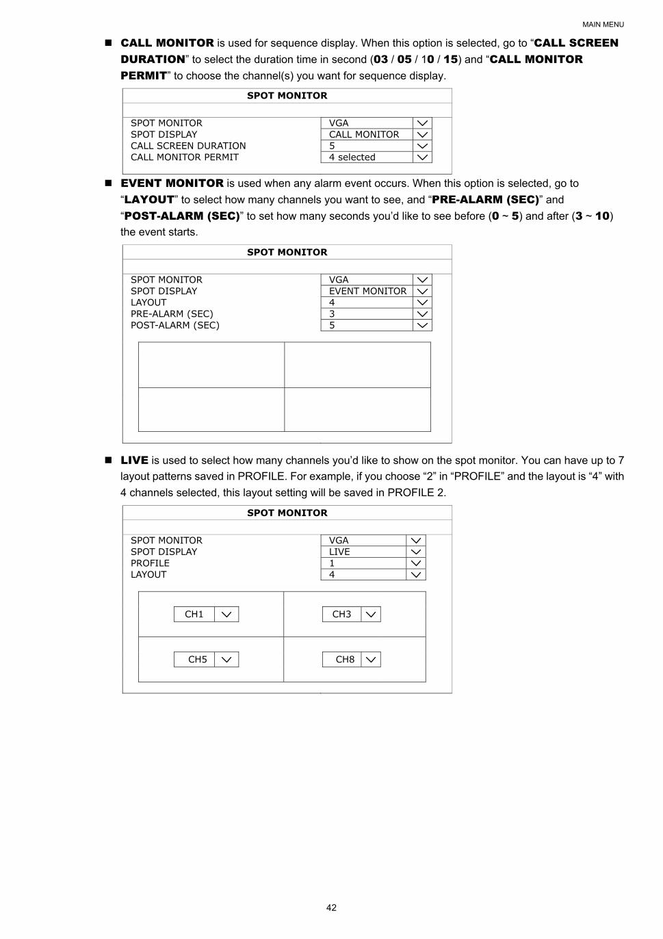
MAIN MENU
42
CALL MONITOR is used for sequence display. When this option is selected, go to “CALL SCREEN DURATION” to select the duration time in second (03 / 05 / 10 / 15) and “CALL MONITOR PERMIT” to choose the channel(s) you want for sequence display.
SPOT MONITOR
SPOT MONITOR VGA SPOT DISPLAY CALL MONITOR CALL SCREEN DURATION 5 CALL MONITOR PERMIT 4 selected
EVENT MONITOR is used when any alarm event occurs. When this option is selected, go to
“LAYOUT” to select how many channels you want to see, and “PRE-ALARM (SEC)” and
“POST-ALARM (SEC)” to set how many seconds you’d like to see before (0 ~ 5) and after (3 ~ 10)
the event starts.
SPOT MONITOR
SPOT MONITOR VGA SPOT DISPLAY EVENT MONITOR LAYOUT 4 PRE-ALARM (SEC) 3 POST-ALARM (SEC) 5
LIVE is used to select how many channels you’d like to show on the spot monitor. You can have up to 7
layout patterns saved in PROFILE. For example, if you choose “2” in “PROFILE” and the layout is “4” with
4 channels selected, this layout setting will be saved in PROFILE 2.
SPOT MONITOR
SPOT MONITOR VGA SPOT DISPLAY LIVE PROFILE 1 LAYOUT 4 CH1 CH3 CH5 CH8
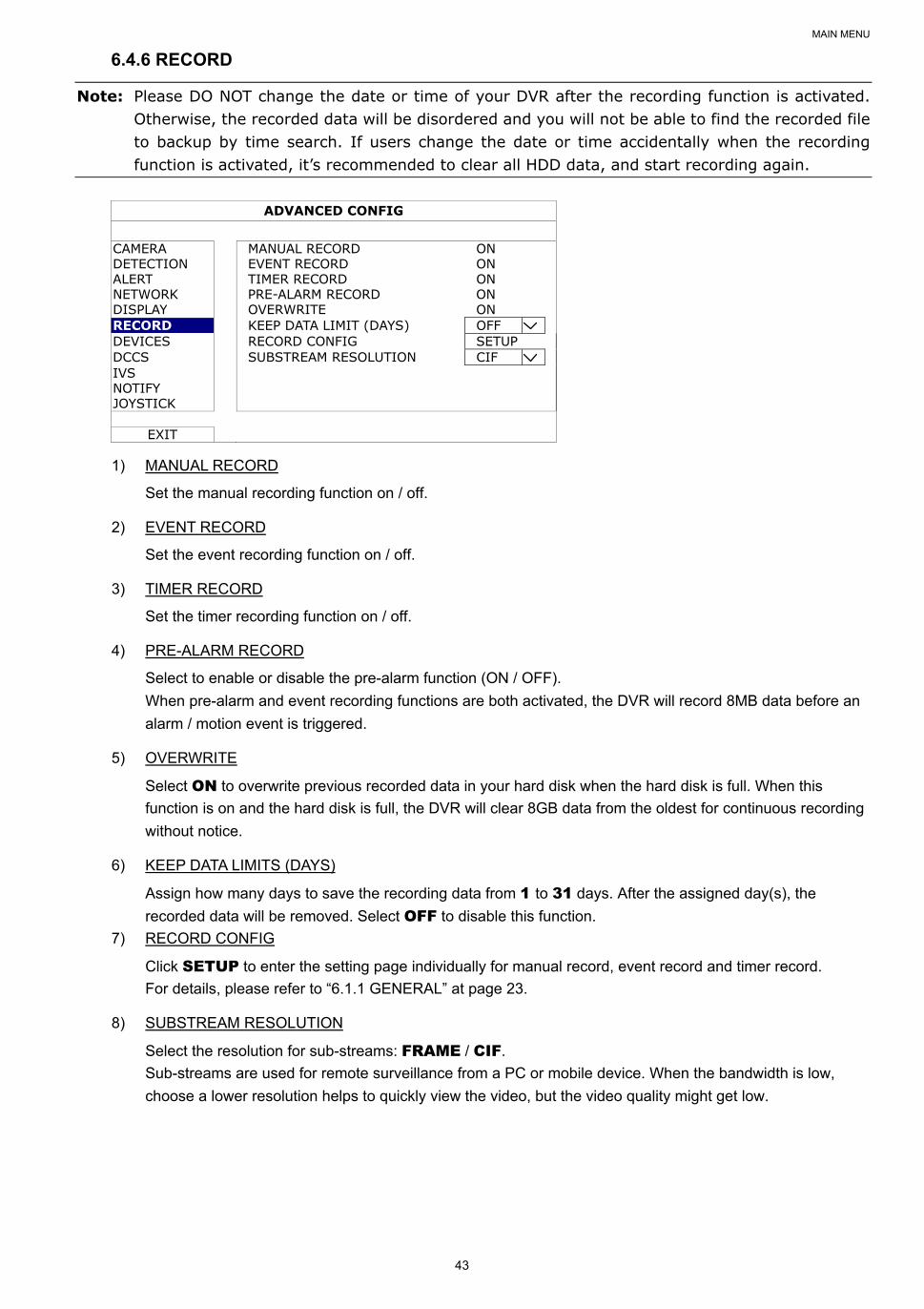
MAIN MENU
43
6.4.6 RECORD
Note: Please DO NOT change the date or time of your DVR after the recording function is activated. Otherwise, the recorded data will be disordered and you will not be able to find the recorded file to backup by time search. If users change the date or time accidentally when the recording function is activated, it’s recommended to clear all HDD data, and start recording again.
ADVANCED CONFIG
CAMERA MANUAL RECORD ON DETECTION EVENT RECORD ON ALERT TIMER RECORD ON NETWORK PRE-ALARM RECORD ON DISPLAY OVERWRITE ON RECORD KEEP DATA LIMIT (DAYS) OFF DEVICES RECORD CONFIG SETUP DCCS SUBSTREAM RESOLUTION CIF IVS NOTIFY JOYSTICK
EXIT
1) MANUAL RECORD
Set the manual recording function on / off.
2) EVENT RECORD
Set the event recording function on / off.
3) TIMER RECORD
Set the timer recording function on / off.
4) PRE-ALARM RECORD
Select to enable or disable the pre-alarm function (ON / OFF).
When pre-alarm and event recording functions are both activated, the DVR will record 8MB data before an
alarm / motion event is triggered.
5) OVERWRITE
Select ON to overwrite previous recorded data in your hard disk when the hard disk is full. When this
function is on and the hard disk is full, the DVR will clear 8GB data from the oldest for continuous recording
without notice.
6) KEEP DATA LIMITS (DAYS)
Assign how many days to save the recording data from 1 to 31 days. After the assigned day(s), the
recorded data will be removed. Select OFF to disable this function.
7) RECORD CONFIG
Click SETUP to enter the setting page individually for manual record, event record and timer record.
For details, please refer to “6.1.1 GENERAL” at page 23.
8) SUBSTREAM RESOLUTION
Select the resolution for sub-streams: FRAME / CIF.
Sub-streams are used for remote surveillance from a PC or mobile device. When the bandwidth is low,
choose a lower resolution helps to quickly view the video, but the video quality might get low.
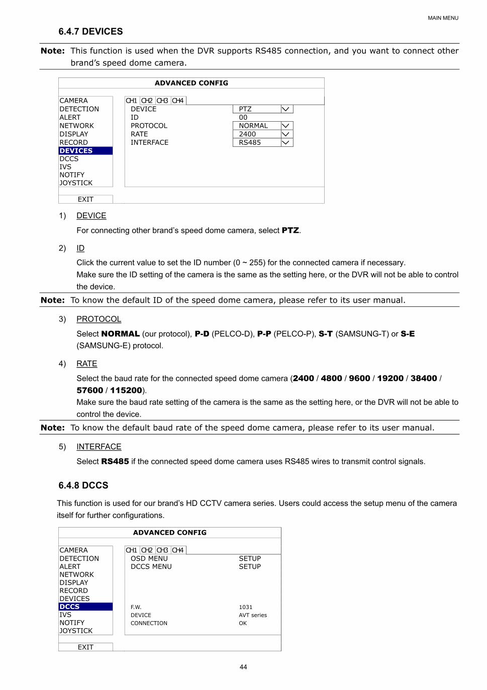
MAIN MENU
44
6.4.7 DEVICES
Note: This function is used when the DVR supports RS485 connection, and you want to connect other brand’s speed dome camera.
ADVANCED CONFIG
CAMERA CH1 CH2 CH3 CH4 DETECTION DEVICE PTZ ALERT ID 00 NETWORK PROTOCOL NORMAL DISPLAY RATE 2400 RECORD INTERFACE RS485 DEVICES DCCS IVS NOTIFY JOYSTICK
EXIT
1) DEVICE
For connecting other brand’s speed dome camera, select PTZ.
2) ID
Click the current value to set the ID number (0 ~ 255) for the connected camera if necessary.
Make sure the ID setting of the camera is the same as the setting here, or the DVR will not be able to control
the device.
Note: To know the default ID of the speed dome camera, please refer to its user manual.
3) PROTOCOL
Select NORMAL (our protocol), P-D (PELCO-D), P-P (PELCO-P), S-T (SAMSUNG-T) or S-E
(SAMSUNG-E) protocol.
4) RATE
Select the baud rate for the connected speed dome camera (2400 / 4800 / 9600 / 19200 / 38400 /
57600 / 115200).
Make sure the baud rate setting of the camera is the same as the setting here, or the DVR will not be able to
control the device.
Note: To know the default baud rate of the speed dome camera, please refer to its user manual.
5) INTERFACE
Select RS485 if the connected speed dome camera uses RS485 wires to transmit control signals.
6.4.8 DCCS
This function is used for our brand’s HD CCTV camera series. Users could access the setup menu of the camera
itself for further configurations.
ADVANCED CONFIG
CAMERA CH1 CH2 CH3 CH4 DETECTION OSD MENU SETUP ALERT DCCS MENU SETUP NETWORK DISPLAY RECORD DEVICES DCCS F.W. 1031 IVS DEVICE AVT series NOTIFY CONNECTION OK JOYSTICK
EXIT
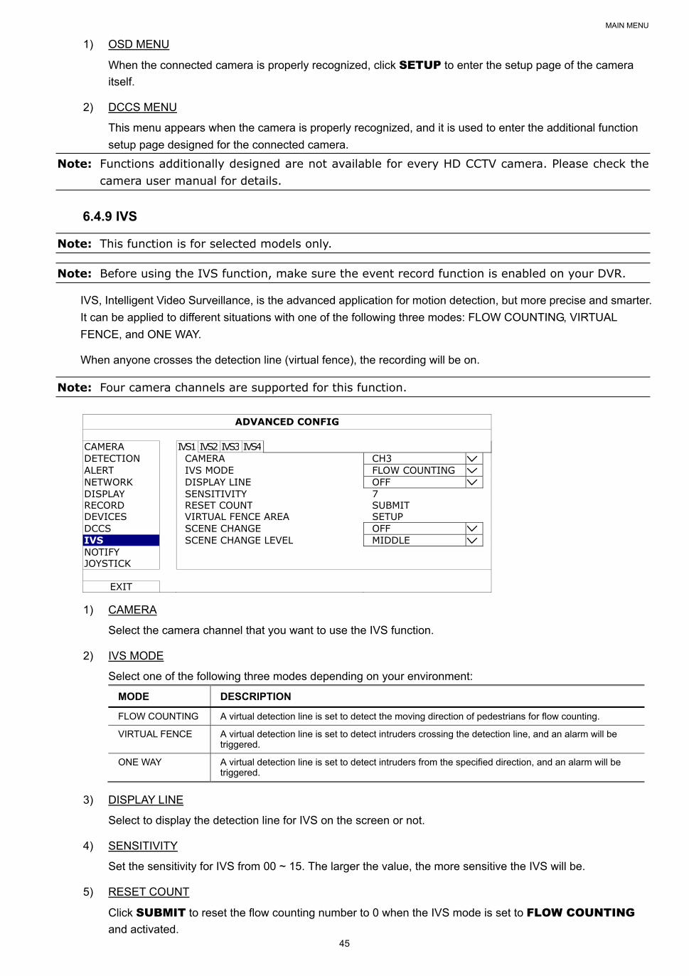
MAIN MENU
45
1) OSD MENU
When the connected camera is properly recognized, click SETUP to enter the setup page of the camera
itself.
2) DCCS MENU
This menu appears when the camera is properly recognized, and it is used to enter the additional function
setup page designed for the connected camera.
Note: Functions additionally designed are not available for every HD CCTV camera. Please check the camera user manual for details.
6.4.9 IVS
Note: This function is for selected models only.
Note: Before using the IVS function, make sure the event record function is enabled on your DVR.
IVS, Intelligent Video Surveillance, is the advanced application for motion detection, but more precise and smarter.
It can be applied to different situations with one of the following three modes: FLOW COUNTING, VIRTUAL
FENCE, and ONE WAY.
When anyone crosses the detection line (virtual fence), the recording will be on.
Note: Four camera channels are supported for this function.
ADVANCED CONFIG
CAMERA IVS1 IVS2 IVS3 IVS4 DETECTION CAMERA CH3 ALERT IVS MODE FLOW COUNTING NETWORK DISPLAY LINE OFF DISPLAY SENSITIVITY 7 RECORD RESET COUNT SUBMIT DEVICES VIRTUAL FENCE AREA SETUP DCCS SCENE CHANGE OFF IVS SCENE CHANGE LEVEL MIDDLE NOTIFY JOYSTICK
EXIT
1) CAMERA
Select the camera channel that you want to use the IVS function.
2) IVS MODE
Select one of the following three modes depending on your environment:
MODE DESCRIPTION
FLOW COUNTING A virtual detection line is set to detect the moving direction of pedestrians for flow counting.
VIRTUAL FENCE A virtual detection line is set to detect intruders crossing the detection line, and an alarm will be triggered.
ONE WAY A virtual detection line is set to detect intruders from the specified direction, and an alarm will be triggered.
3) DISPLAY LINE
Select to display the detection line for IVS on the screen or not.
4) SENSITIVITY
Set the sensitivity for IVS from 00 ~ 15. The larger the value, the more sensitive the IVS will be.
5) RESET COUNT
Click SUBMIT to reset the flow counting number to 0 when the IVS mode is set to FLOW COUNTING
and activated.
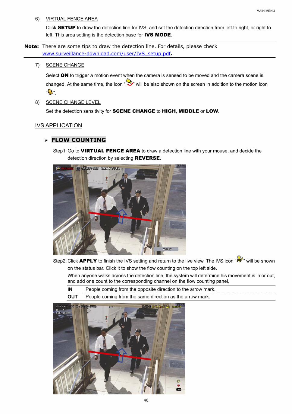
MAIN MENU
46
6) VIRTUAL FENCE AREA
Click SETUP to draw the detection line for IVS, and set the detection direction from left to right, or right to
left. This area setting is the detection base for IVS MODE.
Note: There are some tips to draw the detection line. For details, please check www.surveillance-download.com/user/IVS_setup.pdf.
7) SCENE CHANGE
Select ON to trigger a motion event when the camera is sensed to be moved and the camera scene is
changed. At the same time, the icon “ ” will be also shown on the screen in addition to the motion icon
“ ”.
8) SCENE CHANGE LEVEL
Set the detection sensitivity for SCENE CHANGE to HIGH, MIDDLE or LOW.
IVS APPLICATION
FFLLOOWW CCOOUUNNTTIINNGG
Step1: Go to VIRTUAL FENCE AREA to draw a detection line with your mouse, and decide the
detection direction by selecting REVERSE.
Step2: Click APPLY to finish the IVS setting and return to the live view. The IVS icon “ ” will be shown
on the status bar. Click it to show the flow counting on the top left side.
When anyone walks across the detection line, the system will determine his movement is in or out, and add one count to the corresponding channel on the flow counting panel.
IN People coming from the opposite direction to the arrow mark.
OUT People coming from the same direction as the arrow mark.
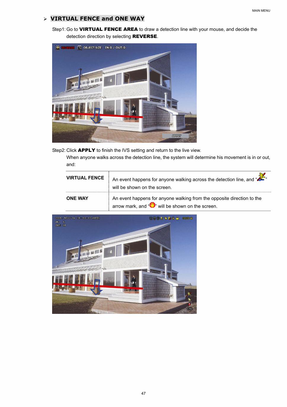
MAIN MENU
47
VVIIRRTTUUAALL FFEENNCCEE aanndd OONNEE WWAAYY
Step1: Go to VIRTUAL FENCE AREA to draw a detection line with your mouse, and decide the
detection direction by selecting REVERSE.
Step2: Click APPLY to finish the IVS setting and return to the live view.
When anyone walks across the detection line, the system will determine his movement is in or out,
and:
VIRTUAL FENCE An event happens for anyone walking across the detection line, and “ ”
will be shown on the screen.
ONE WAY An event happens for anyone walking from the opposite direction to the
arrow mark, and “ ” will be shown on the screen.
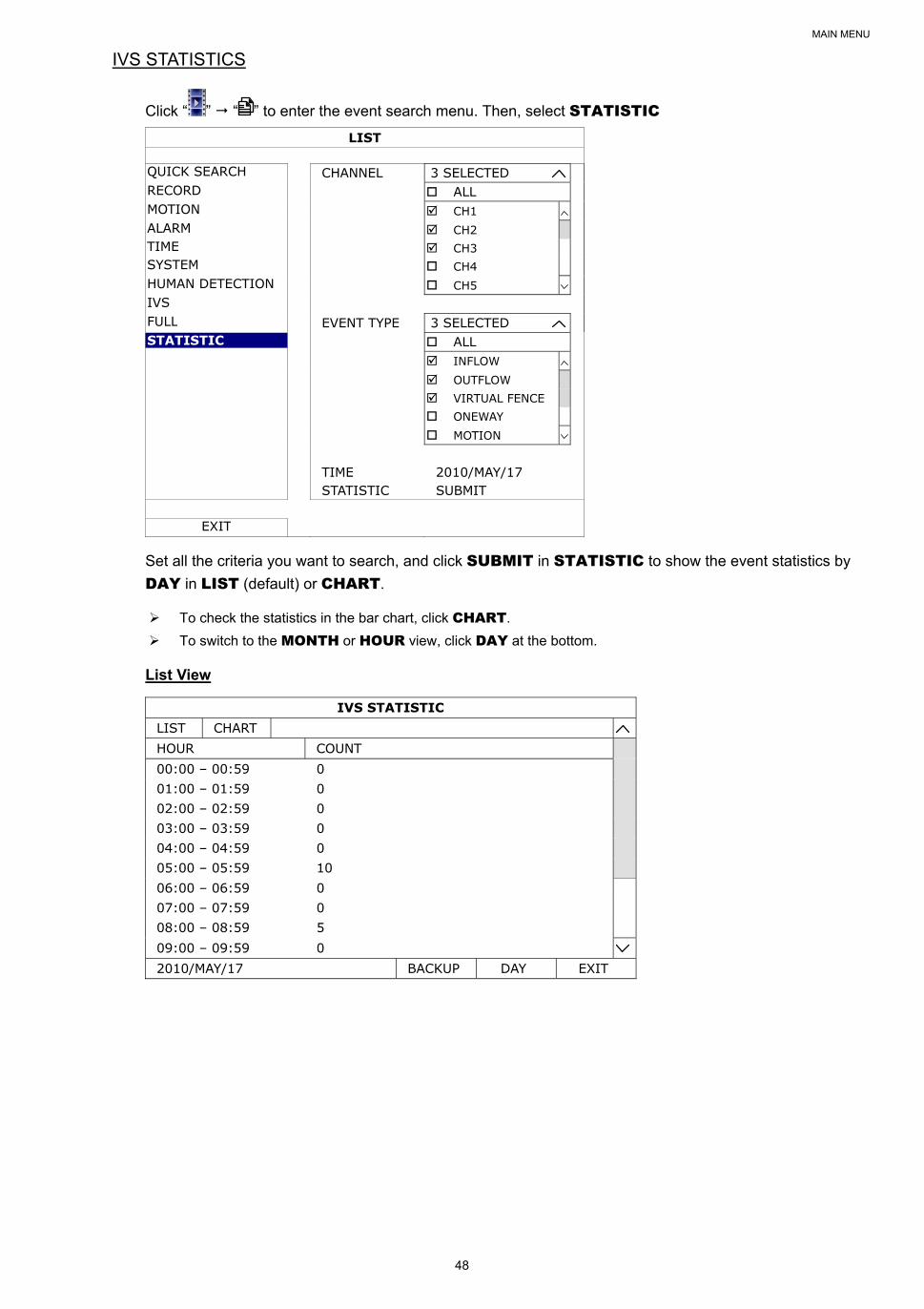
MAIN MENU
48
IVS STATISTICS
Click “ ” “ ” to enter the event search menu. Then, select STATISTIC
LIST
QUICK SEARCH CHANNEL 3 SELECTED RECORD ALL MOTION CH1 ALARM CH2 TIME CH3 SYSTEM CH4 HUMAN DETECTION CH5 IVS FULL EVENT TYPE 3 SELECTED STATISTIC ALL INFLOW OUTFLOW VIRTUAL FENCE ONEWAY MOTION TIME 2010/MAY/17 STATISTIC SUBMIT
EXIT
Set all the criteria you want to search, and click SUBMIT in STATISTIC to show the event statistics by
DAY in LIST (default) or CHART.
To check the statistics in the bar chart, click CHART.
To switch to the MONTH or HOUR view, click DAY at the bottom.
List View
IVS STATISTIC LIST CHART HOUR COUNT 00:00 – 00:59 0 01:00 – 01:59 0 02:00 – 02:59 0 03:00 – 03:59 0 04:00 – 04:59 0 05:00 – 05:59 10 06:00 – 06:59 0 07:00 – 07:59 0 08:00 – 08:59 5 09:00 – 09:59 0 2010/MAY/17 BACKUP DAY EXIT
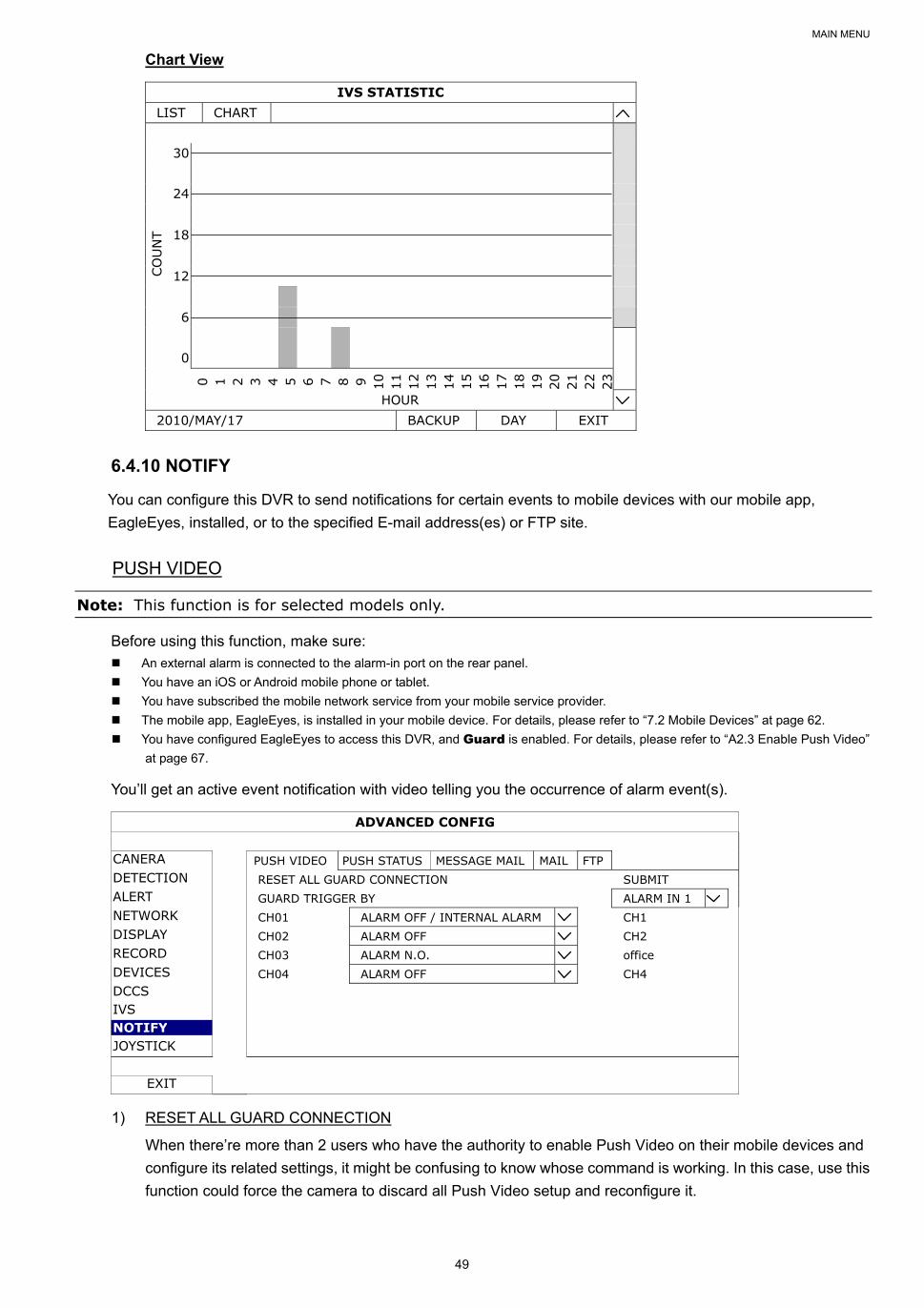
MAIN MENU
49
Chart View
IVS STATISTIC LIST CHART 30
CO
UN
T
24
18
12
6
0
0 1 2 3 4 5 6 7 8 9 10
11
12
13
14
15
16
17
18
19
20
21
22
23
HOUR 2010/MAY/17 BACKUP DAY EXIT
6.4.10 NOTIFY
You can configure this DVR to send notifications for certain events to mobile devices with our mobile app,
EagleEyes, installed, or to the specified E-mail address(es) or FTP site.
PUSH VIDEO
Note: This function is for selected models only.
Before using this function, make sure: An external alarm is connected to the alarm-in port on the rear panel.
You have an iOS or Android mobile phone or tablet.
You have subscribed the mobile network service from your mobile service provider.
The mobile app, EagleEyes, is installed in your mobile device. For details, please refer to “7.2 Mobile Devices” at page 62.
You have configured EagleEyes to access this DVR, and Guard is enabled. For details, please refer to “A2.3 Enable Push Video”
at page 67.
You’ll get an active event notification with video telling you the occurrence of alarm event(s).
ADVANCED CONFIG
CANERA PUSH VIDEO PUSH STATUS MESSAGE MAIL MAIL FTP DETECTION RESET ALL GUARD CONNECTION SUBMIT ALERT GUARD TRIGGER BY ALARM IN 1 NETWORK CH01 ALARM OFF / INTERNAL ALARM CH1 DISPLAY CH02 ALARM OFF CH2 RECORD CH03 ALARM N.O. office DEVICES CH04 ALARM OFF CH4 DCCS IVS NOTIFY JOYSTICK
EXIT
1) RESET ALL GUARD CONNECTION
When there’re more than 2 users who have the authority to enable Push Video on their mobile devices and
configure its related settings, it might be confusing to know whose command is working. In this case, use this
function could force the camera to discard all Push Video setup and reconfigure it.

MAIN MENU
50
2) GUARD TRIGGER BY
Specify which alarm device (alarm-in) should be used when GUARD is enabled from your iOS or Android
mobile device.
3) ALARM TYPE
Select the external alarm type to ALARM NO., ALARM N.C. and INTERNAL ALARM.
4) CH01 ~ 04
Enter the text you want to see when your iOS or Android mobile device receives Push Video. The default
text is the channel number.
PUSH STATUS
Before using this function, make sure:
You have an iOS or Android mobile phone or tablet. You have subscribed the mobile network service from your mobile service provider.
The mobile app, EagleEyes, is installed in your mobile device. For details, please refer to “7.2 Mobile Devices” at page 62.
You have configured EagleEyes to access this DVR, and Guard is enabled. For details, please refer to “A2.3 Enable Push Video”
at page 67.
You’ll get a text message telling you the occurrence of selected system event(s).
ADVANCED CONFIG
CANERA PUSH VIDEO PUSH STATUS MESSAGE MAIL MAIL FTP DETECTION ACTION ON ALERT EVENT ALL NETWORK VIDEO LOSS DISPLAY HDD FULL RECORD POWER ON DEVICES HDD (CLEAR / NO HDD / OVER TEMPERATURE) DCCS NET LOGIN IVS KEY UNLOCK NOTIFY UPS JOYSTICK SYSTEM ABNORMAL
EXIT
Step1: Switch ACTION to ON.
Step2: Select the system event(s) you want to get notified via your mobile device.
Step3: Enable GUARD in EagleEyes on your mobile device, and try to trigger a system event to see if you’ll get
Push Status.
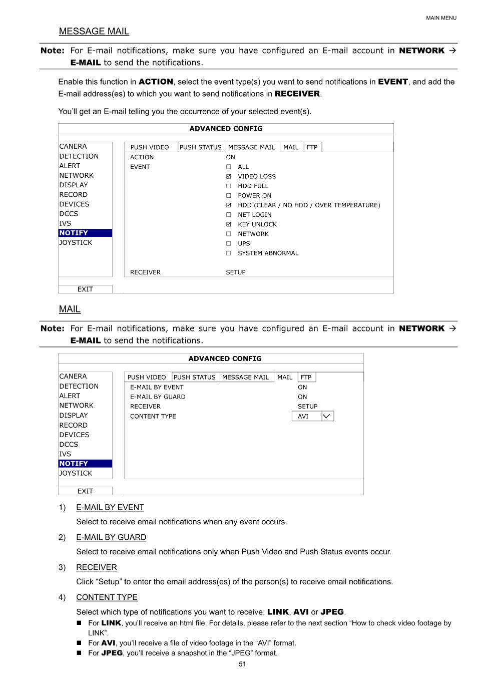
MAIN MENU
51
MESSAGE MAIL
Note: For E-mail notifications, make sure you have configured an E-mail account in NETWORK E-MAIL to send the notifications.
Enable this function in ACTION, select the event type(s) you want to send notifications in EVENT, and add the
E-mail address(es) to which you want to send notifications in RECEIVER.
You’ll get an E-mail telling you the occurrence of your selected event(s).
ADVANCED CONFIG
CANERA PUSH VIDEO PUSH STATUS MESSAGE MAIL MAIL FTP DETECTION ACTION ON ALERT EVENT ALL NETWORK VIDEO LOSS DISPLAY HDD FULL RECORD POWER ON DEVICES HDD (CLEAR / NO HDD / OVER TEMPERATURE) DCCS NET LOGIN IVS KEY UNLOCK NOTIFY NETWORK JOYSTICK UPS SYSTEM ABNORMAL RECEIVER SETUP
EXIT
Note: For E-mail notifications, make sure you have configured an E-mail account in NETWORK E-MAIL to send the notifications.
ADVANCED CONFIG
CANERA PUSH VIDEO PUSH STATUS MESSAGE MAIL MAIL FTP DETECTION E-MAIL BY EVENT ON ALERT E-MAIL BY GUARD ON NETWORK RECEIVER SETUP DISPLAY CONTENT TYPE AVI RECORD DEVICES DCCS IVS NOTIFY JOYSTICK
EXIT
1) E-MAIL BY EVENT
Select to receive email notifications when any event occurs.
2) E-MAIL BY GUARD
Select to receive email notifications only when Push Video and Push Status events occur.
3) RECEIVER
Click “Setup” to enter the email address(es) of the person(s) to receive email notifications.
4) CONTENT TYPE
Select which type of notifications you want to receive: LINK, AVI or JPEG. For LINK, you’ll receive an html file. For details, please refer to the next section “How to check video footage by
LINK”. For AVI, you’ll receive a file of video footage in the “AVI” format. For JPEG, you’ll receive a snapshot in the “JPEG” format.
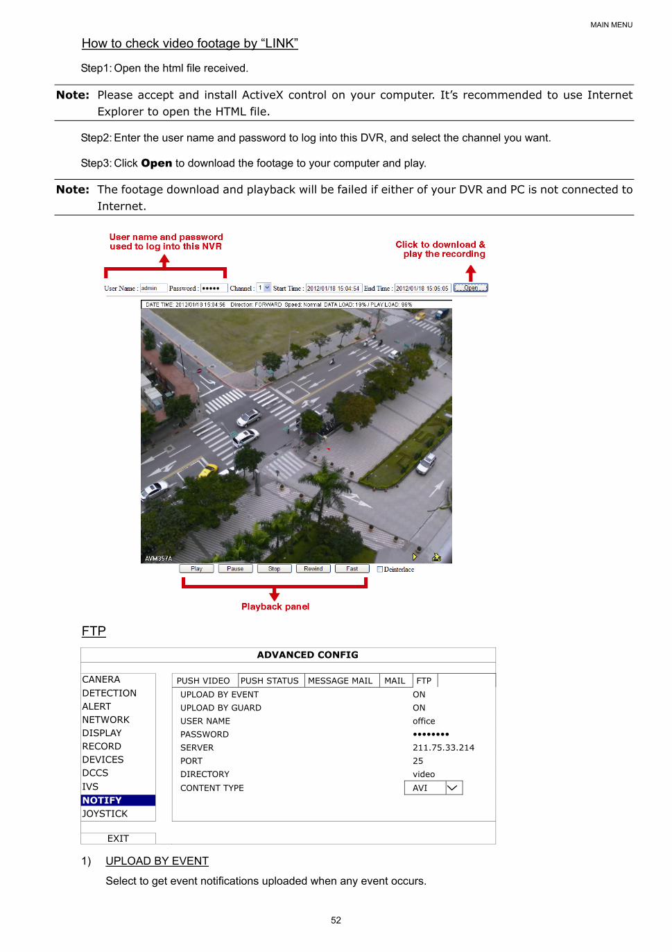
MAIN MENU
52
How to check video footage by “LINK”
Step1: Open the html file received.
Note: Please accept and install ActiveX control on your computer. It’s recommended to use Internet Explorer to open the HTML file.
Step2: Enter the user name and password to log into this DVR, and select the channel you want.
Step3: Click Open to download the footage to your computer and play.
Note: The footage download and playback will be failed if either of your DVR and PC is not connected to Internet.
FTP
ADVANCED CONFIG
CANERA PUSH VIDEO PUSH STATUS MESSAGE MAIL MAIL FTP DETECTION UPLOAD BY EVENT ON ALERT UPLOAD BY GUARD ON NETWORK USER NAME office DISPLAY PASSWORD RECORD SERVER 211.75.33.214 DEVICES PORT 25 DCCS DIRECTORY video IVS CONTENT TYPE AVI NOTIFY JOYSTICK
EXIT
1) UPLOAD BY EVENT
Select to get event notifications uploaded when any event occurs.
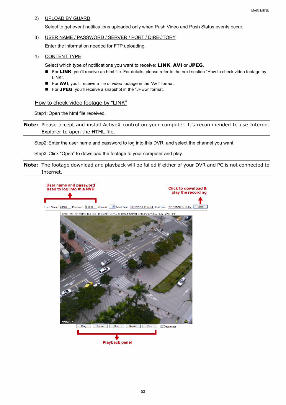
MAIN MENU
53
2) UPLOAD BY GUARD
Select to get event notifications uploaded only when Push Video and Push Status events occur.
3) USER NAME / PASSWORD / SERVER / PORT / DIRECTORY
Enter the information needed for FTP uploading.
4) CONTENT TYPE
Select which type of notifications you want to receive: LINK, AVI or JPEG. For LINK, you’ll receive an html file. For details, please refer to the next section “How to check video footage by
LINK”. For AVI, you’ll receive a file of video footage in the “AVI” format. For JPEG, you’ll receive a snapshot in the “JPEG” format.
How to check video footage by “LINK”
Step1: Open the html file received.
Note: Please accept and install ActiveX control on your computer. It’s recommended to use Internet Explorer to open the HTML file.
Step2: Enter the user name and password to log into this DVR, and select the channel you want.
Step3: Click “Open” to download the footage to your computer and play.
Note: The footage download and playback will be failed if either of your DVR and PC is not connected to Internet.
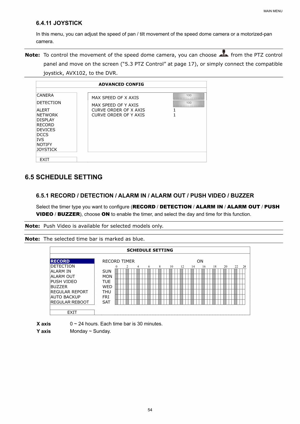
MAIN MENU
54
6.4.11 JOYSTICK
In this menu, you can adjust the speed of pan / tilt movement of the speed dome camera or a motorized-pan
camera.
Note: To control the movement of the speed dome camera, you can choose from the PTZ control
panel and move on the screen (“5.3 PTZ Control” at page 17), or simply connect the compatible
joystick, AVX102, to the DVR.
ADVANCED CONFIG
CANERA MAX SPEED OF X AXIS 100
DETECTION MAX SPEED OF Y AXIS 100
ALERT CURVE ORDER OF X AXIS 1 NETWORK CURVE ORDER OF Y AXIS 1 DISPLAY RECORD DEVICES DCCS IVS NOTIFY JOYSTICK
EXIT
6.5 SCHEDULE SETTING
6.5.1 RECORD / DETECTION / ALARM IN / ALARM OUT / PUSH VIDEO / BUZZER
Select the timer type you want to configure (RECORD / DETECTION / ALARM IN / ALARM OUT / PUSH VIDEO / BUZZER), choose ON to enable the timer, and select the day and time for this function.
Note: Push Video is available for selected models only.
Note: The selected time bar is marked as blue.
SCHEDULE SETTING
RECORD RECORD TIMER ON DETECTION 0 2 4 6 8 10 12 14 16 18 20 22 24 ALARM IN SUN ALARM OUT MON PUSH VIDEO TUE BUZZER WED REGULAR REPORT THU AUTO BACKUP FRI REGULAR REBOOT SAT
EXIT
X axis 0 ~ 24 hours. Each time bar is 30 minutes.
Y axis Monday ~ Sunday.
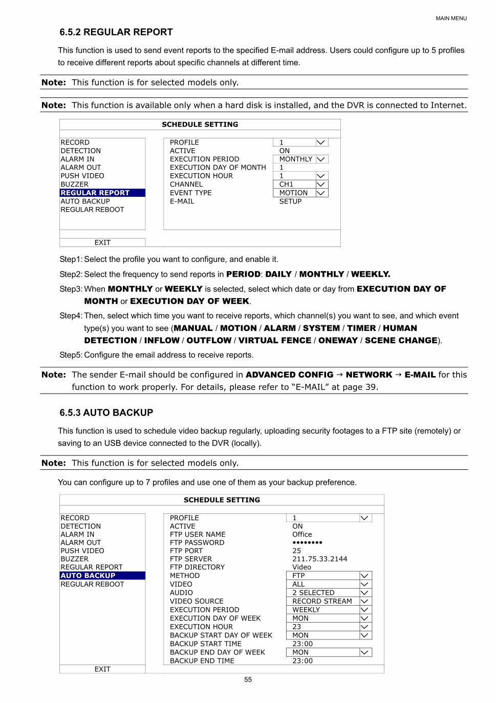
MAIN MENU
55
6.5.2 REGULAR REPORT
This function is used to send event reports to the specified E-mail address. Users could configure up to 5 profiles
to receive different reports about specific channels at different time.
Note: This function is for selected models only.
Note: This function is available only when a hard disk is installed, and the DVR is connected to Internet.
SCHEDULE SETTING
RECORD PROFILE 1 DETECTION ACTIVE ON ALARM IN EXECUTION PERIOD MONTHLY ALARM OUT EXECUTION DAY OF MONTH 1 PUSH VIDEO EXECUTION HOUR 1 BUZZER CHANNEL CH1 REGULAR REPORT EVENT TYPE MOTION AUTO BACKUP E-MAIL SETUP REGULAR REBOOT
EXIT
Step1: Select the profile you want to configure, and enable it.
Step2: Select the frequency to send reports in PERIOD: DAILY / MONTHLY / WEEKLY.
Step3: When MONTHLY or WEEKLY is selected, select which date or day from EXECUTION DAY OF MONTH or EXECUTION DAY OF WEEK.
Step4: Then, select which time you want to receive reports, which channel(s) you want to see, and which event
type(s) you want to see (MANUAL / MOTION / ALARM / SYSTEM / TIMER / HUMAN DETECTION / INFLOW / OUTFLOW / VIRTUAL FENCE / ONEWAY / SCENE CHANGE).
Step5: Configure the email address to receive reports.
Note: The sender E-mail should be configured in ADVANCED CONFIG NETWORK E-MAIL for this function to work properly. For details, please refer to “E-MAIL” at page 39.
6.5.3 AUTO BACKUP
This function is used to schedule video backup regularly, uploading security footages to a FTP site (remotely) or
saving to an USB device connected to the DVR (locally).
Note: This function is for selected models only.
You can configure up to 7 profiles and use one of them as your backup preference.
SCHEDULE SETTING
RECORD PROFILE 1 DETECTION ACTIVE ON ALARM IN FTP USER NAME Office ALARM OUT FTP PASSWORD PUSH VIDEO FTP PORT 25 BUZZER FTP SERVER 211.75.33.2144 REGULAR REPORT FTP DIRECTORY Video AUTO BACKUP METHOD FTP REGULAR REBOOT VIDEO ALL AUDIO 2 SELECTED VIDEO SOURCE RECORD STREAM EXECUTION PERIOD WEEKLY EXECUTION DAY OF WEEK MON EXECUTION HOUR 23 BACKUP START DAY OF WEEK MON BACKUP START TIME 23:00 BACKUP END DAY OF WEEK MON BACKUP END TIME 23:00
EXIT
MAIN MENU
56
1) PROFILE
Select the profile you want to configure.
2) ACTIVE
Switch to ON to enable the selected profile.
3) FTP USER NAME / FTP PASSWORD / FTP PORT / FTP SERVER / FTP DIRECTORY
Enter all the information needed to access the FTP site you want if you want to upload those footages to an
FTP site.
4) METHOD
Choose where you to save those footages: FTP / USB DEVICE.
5) VIDEO / AUDIO
Select the video / audio channels you want to backup.
6) VIDEO SOURCE
Choose RECORD STREAM or SUB STREAM:
RECORD STREAM: The video quality is good, but it also consumes much storage.
SUB STREAM: It consumes less storage, but the video quality might be not satisfactory.
7) EXECUTION PERIOD
Select how often you want to backup footages: WEEKLY or DAILY.
8) EXECUTION DAY OF WEEK
This option is available only when WEEKLY is chosen. Select one day from MON ~ SUN.
For example, if you want to backup video data from Monday, 01:00am to Friday, 23:59pm on every Saturday,
09:00am, choose SAT here.
9) EXECUTION HOUR
Select an exact hour to start rebooting from 0 ~ 23.
For example, if you want to backup video data from Monday, 01:00am to Friday, 23:59pm on every Saturday,
09:00am, choose 9 here.
10) BACKUP START DAY OF WEEK
This option is available only when WEEKLY is chosen. Select one day from MON ~ SUN.
For example, if you want to backup video data from Monday, 01:00am to Friday, 23:59pm on every Saturday,
choose MON here.
11) BACKUP START TIME
Enter the start time for backup.
For example, if you want to backup video data from Monday, 01:00am to Friday, 23:59pm on every Saturday,
enter 01:00 here.
12) BACKUP END DAY OF WEEK
This option is available only when WEEKLY is chosen. Select one day from MON ~ SUN.
For example, if you want to backup video data from Monday, 01:00am to Friday, 23:59pm on every Saturday,
choose FRI here.
13) BACKUP END TIME
Enter the end time for backup.
For example, if you want to backup video data from Monday, 01:00am to Friday, 23:59pm on every Saturday,
enter 23:59 here.
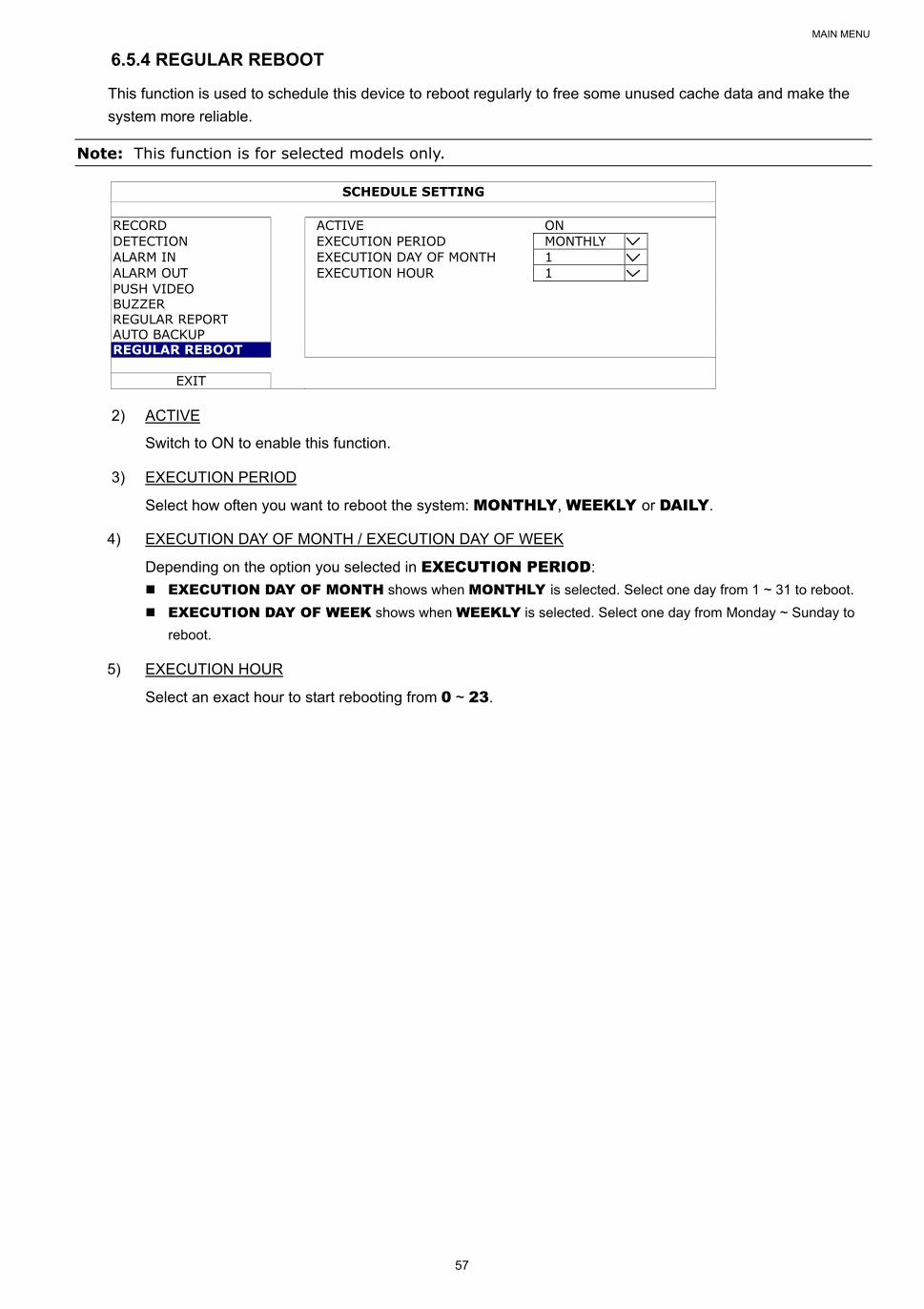
MAIN MENU
57
6.5.4 REGULAR REBOOT
This function is used to schedule this device to reboot regularly to free some unused cache data and make the
system more reliable.
Note: This function is for selected models only.
SCHEDULE SETTING
RECORD ACTIVE ON DETECTION EXECUTION PERIOD MONTHLY ALARM IN EXECUTION DAY OF MONTH 1 ALARM OUT EXECUTION HOUR 1 PUSH VIDEO BUZZER REGULAR REPORT AUTO BACKUP REGULAR REBOOT
EXIT
2) ACTIVE
Switch to ON to enable this function.
3) EXECUTION PERIOD
Select how often you want to reboot the system: MONTHLY, WEEKLY or DAILY.
4) EXECUTION DAY OF MONTH / EXECUTION DAY OF WEEK
Depending on the option you selected in EXECUTION PERIOD:
EXECUTION DAY OF MONTH shows when MONTHLY is selected. Select one day from 1 ~ 31 to reboot.
EXECUTION DAY OF WEEK shows when WEEKLY is selected. Select one day from Monday ~ Sunday to
reboot.
5) EXECUTION HOUR
Select an exact hour to start rebooting from 0 ~ 23.
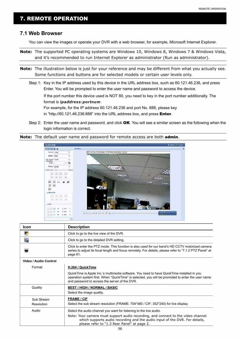
REMOTE OPERATION
58
7. REMOTE OPERATION
7.1 Web Browser
You can view the images or operate your DVR with a web browser, for example, Microsoft Internet Explorer.
Note: The supported PC operating systems are Windows 10, Windows 8, Windows 7 & Windows Vista, and it’s recommended to run Internet Explorer as administrator (Run as administrator).
Note: The illustration below is just for your reference and may be different from what you actually see. Some functions and buttons are for selected models or certain user levels only.
Step 1: Key in the IP address used by this device in the URL address box, such as 60.121.46.236, and press
Enter. You will be prompted to enter the user name and password to access the device.
If the port number this device used is NOT 80, you need to key in the port number additionally. The
format is ipaddress:portnum.
For example, for the IP address 60.121.46.236 and port No. 888, please key
in ”http://60.121.46.236:888” into the URL address box, and press Enter.
Step 2: Enter the user name and password, and click OK. You will see a similar screen as the following when the
login information is correct.
Note: The default user name and password for remote access are both admin.
Icon Description
Click to go to the live view of the DVR.
Click to go to the detailed DVR setting.
Click to enter the PTZ mode. This function is also used for our band’s HD CCTV motorized camera series to adjust its focal length and focus remotely. For details, please refer to “7.1.2 PTZ Panel” at page 61.
Video / Audio Control
Format H.264 / QuickTime
QuickTime is Apple Inc.’s multimedia software. You need to have QuickTime installed in you operation system first. When “QuickTime” is selected, you will be promoted to enter the user name and password to access the server of the DVR.
Quality BEST / HIGH / NORMAL / BASIC
Select the image quality.
Sub Stream
Resolution
FRAME / CIF
Select the sub stream resolution (FRAME: 704*480 / CIF: 352*240) for live display.
Audio Select the audio channel you want for listening to the live audio.
Note: Your camera must support audio recording, and connect to the video channel which supports audio recording and the audio input of the DVR. For details, please refer to “1.3 Rear Panel” at page 2.
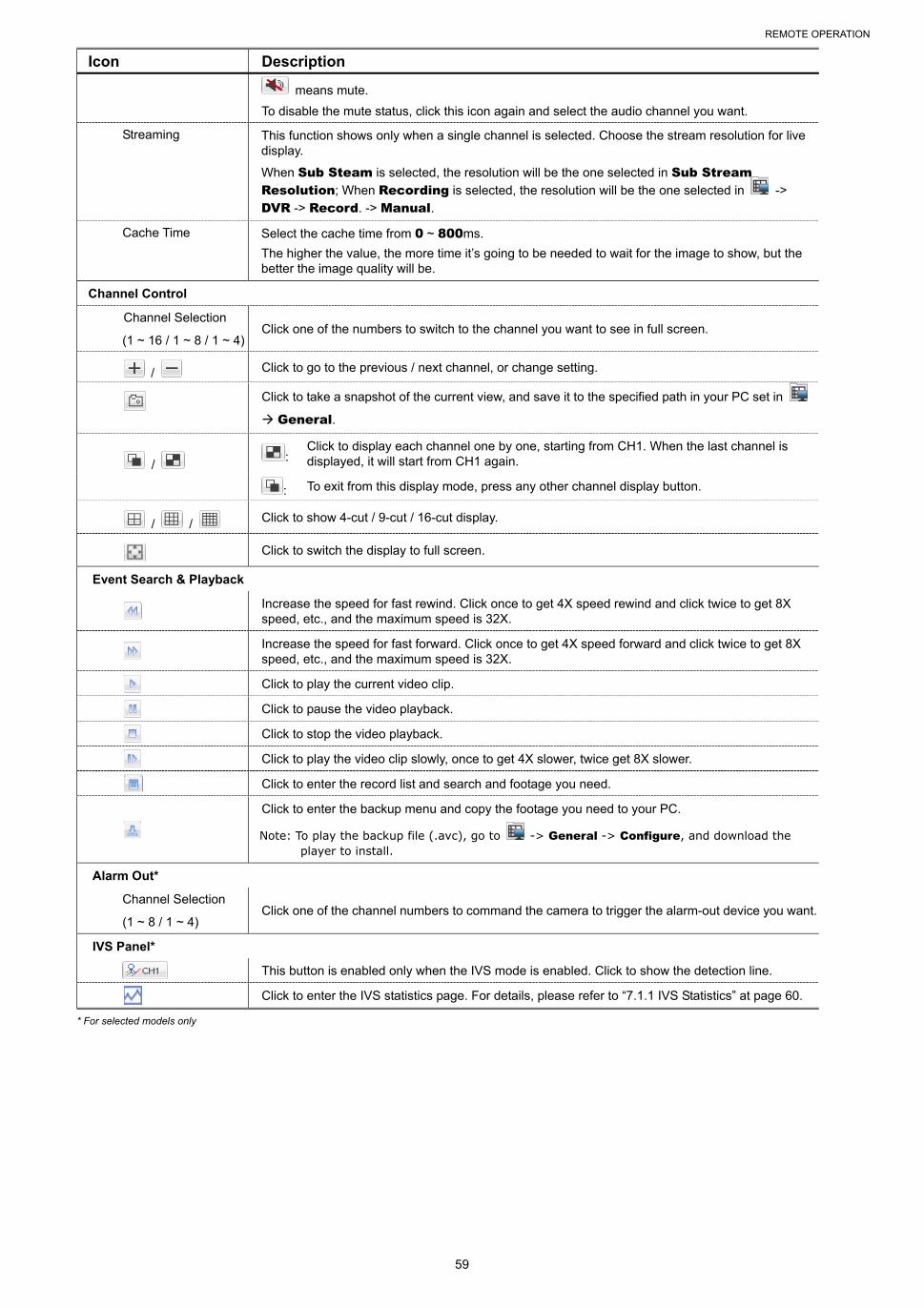
REMOTE OPERATION
59
Icon Description
means mute.
To disable the mute status, click this icon again and select the audio channel you want.
Streaming This function shows only when a single channel is selected. Choose the stream resolution for live display.
When Sub Steam is selected, the resolution will be the one selected in Sub Stream Resolution; When Recording is selected, the resolution will be the one selected in ->
DVR -> Record. -> Manual.
Cache Time Select the cache time from 0 ~ 800ms.
The higher the value, the more time it’s going to be needed to wait for the image to show, but the better the image quality will be.
Channel Control
Channel Selection
(1 ~ 16 / 1 ~ 8 / 1 ~ 4) Click one of the numbers to switch to the channel you want to see in full screen.
/ Click to go to the previous / next channel, or change setting.
Click to take a snapshot of the current view, and save it to the specified path in your PC set in
General.
/ :
Click to display each channel one by one, starting from CH1. When the last channel is displayed, it will start from CH1 again.
: To exit from this display mode, press any other channel display button.
/ / Click to show 4-cut / 9-cut / 16-cut display.
Click to switch the display to full screen.
Event Search & Playback
Increase the speed for fast rewind. Click once to get 4X speed rewind and click twice to get 8X speed, etc., and the maximum speed is 32X.
Increase the speed for fast forward. Click once to get 4X speed forward and click twice to get 8X speed, etc., and the maximum speed is 32X.
Click to play the current video clip.
Click to pause the video playback.
Click to stop the video playback.
Click to play the video clip slowly, once to get 4X slower, twice get 8X slower.
Click to enter the record list and search and footage you need.
Click to enter the backup menu and copy the footage you need to your PC.
Note: To play the backup file (.avc), go to -> General -> Configure, and download the player to install.
Alarm Out*
Channel Selection
(1 ~ 8 / 1 ~ 4) Click one of the channel numbers to command the camera to trigger the alarm-out device you want.
IVS Panel*
This button is enabled only when the IVS mode is enabled. Click to show the detection line.
Click to enter the IVS statistics page. For details, please refer to “7.1.1 IVS Statistics” at page 60.
* For selected models only
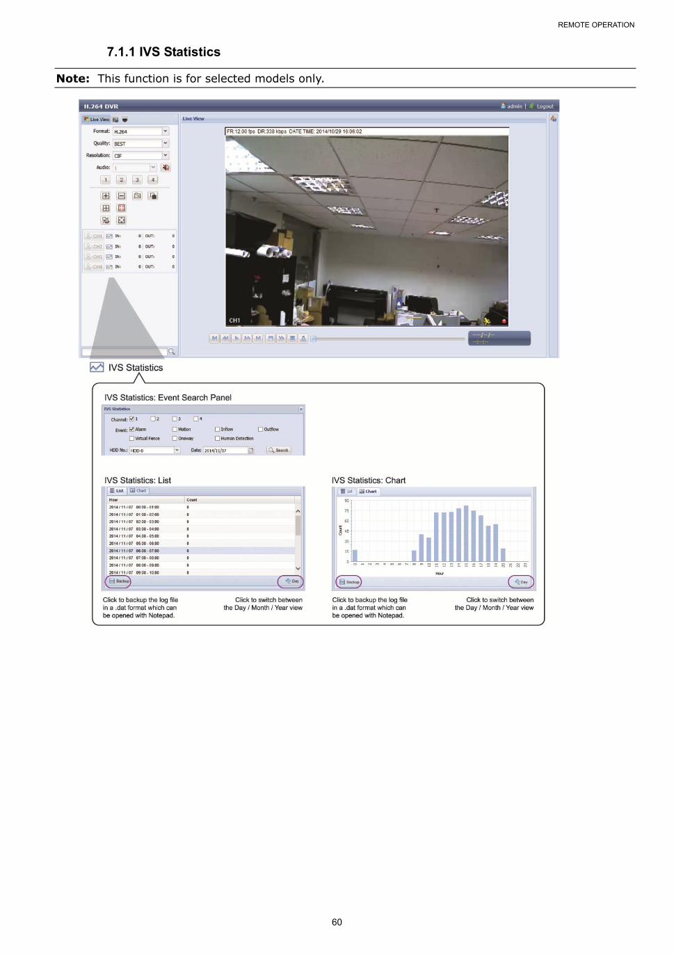
REMOTE OPERATION
60
7.1.1 IVS Statistics
Note: This function is for selected models only.
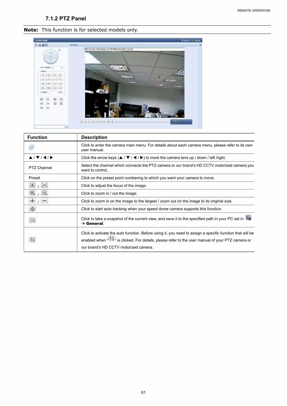
REMOTE OPERATION
61
7.1.2 PTZ Panel
Note: This function is for selected models only.
Function Description
Click to enter the camera main menu. For details about each camera menu, please refer to its own user manual.
/ / / Click the arrow keys ( / / / ) to more the camera lens up / down / left /right.
PTZ Channel Select the channel which connects the PTZ camera or our brand’s HD CCTV motorized camera you want to control.
Preset Click on the preset point numbering to which you want your camera to move.
/ Click to adjust the focus of the image.
/ Click to zoom in / out the image.
/ Click to zoom in on the image to the largest / zoom out on the image to its original size.
Click to start auto tracking when your speed dome camera supports this function.
Click to take a snapshot of the current view, and save it to the specified path in your PC set in General.
Click to activate the auto function. Before using it, you need to assign a specific function that will be
enabled when “ ” is clicked. For details, please refer to the user manual of your PTZ camera or
our brand’s HD CCTV motorized camera.
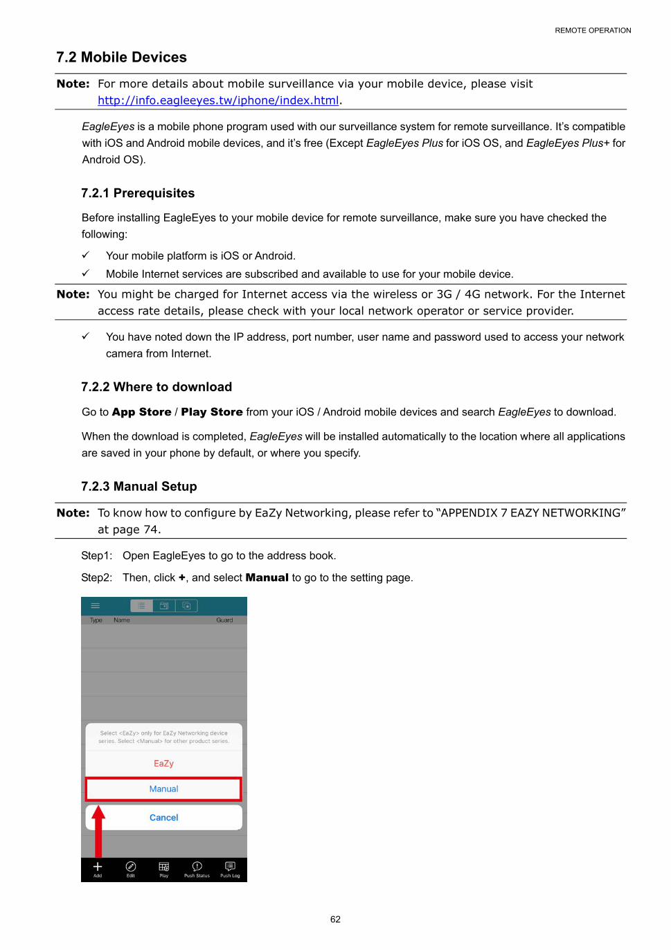
REMOTE OPERATION
62
7.2 Mobile Devices
Note: For more details about mobile surveillance via your mobile device, please visit http://info.eagleeyes.tw/iphone/index.html.
EagleEyes is a mobile phone program used with our surveillance system for remote surveillance. It’s compatible
with iOS and Android mobile devices, and it’s free (Except EagleEyes Plus for iOS OS, and EagleEyes Plus+ for
Android OS).
7.2.1 Prerequisites
Before installing EagleEyes to your mobile device for remote surveillance, make sure you have checked the
following:
Your mobile platform is iOS or Android.
Mobile Internet services are subscribed and available to use for your mobile device.
Note: You might be charged for Internet access via the wireless or 3G / 4G network. For the Internet access rate details, please check with your local network operator or service provider.
You have noted down the IP address, port number, user name and password used to access your network
camera from Internet.
7.2.2 Where to download
Go to App Store / Play Store from your iOS / Android mobile devices and search EagleEyes to download.
When the download is completed, EagleEyes will be installed automatically to the location where all applications
are saved in your phone by default, or where you specify.
7.2.3 Manual Setup
Note: To know how to configure by EaZy Networking, please refer to “APPENDIX 7 EAZY NETWORKING” at page 74.
Step1: Open EagleEyes to go to the address book.
Step2: Then, click +, and select Manual to go to the setting page.
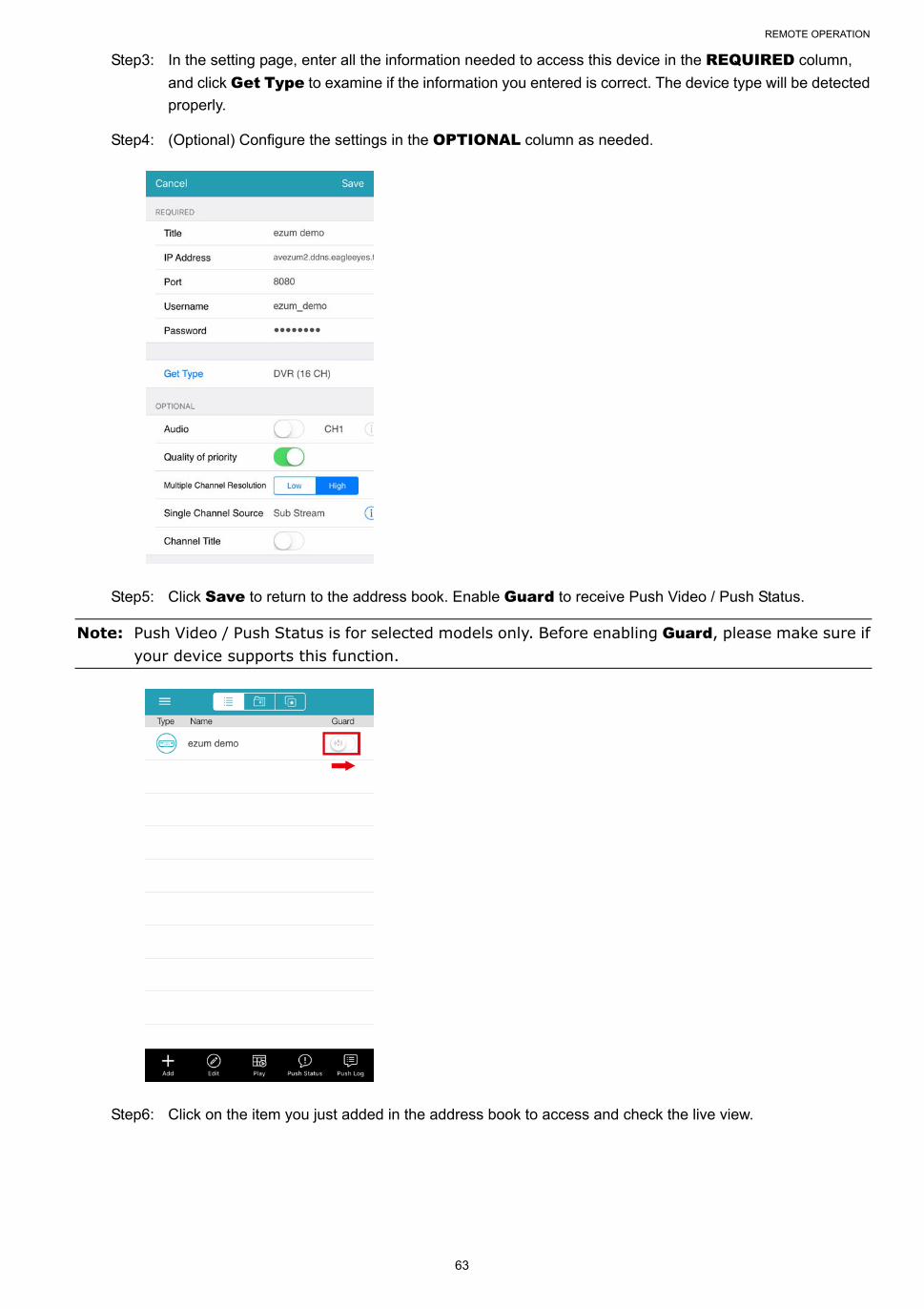
REMOTE OPERATION
63
Step3: In the setting page, enter all the information needed to access this device in the REQUIRED column,
and click Get Type to examine if the information you entered is correct. The device type will be detected
properly.
Step4: (Optional) Configure the settings in the OPTIONAL column as needed.
Step5: Click Save to return to the address book. Enable Guard to receive Push Video / Push Status.
Note: Push Video / Push Status is for selected models only. Before enabling Guard, please make sure if your device supports this function.
Step6: Click on the item you just added in the address book to access and check the live view.
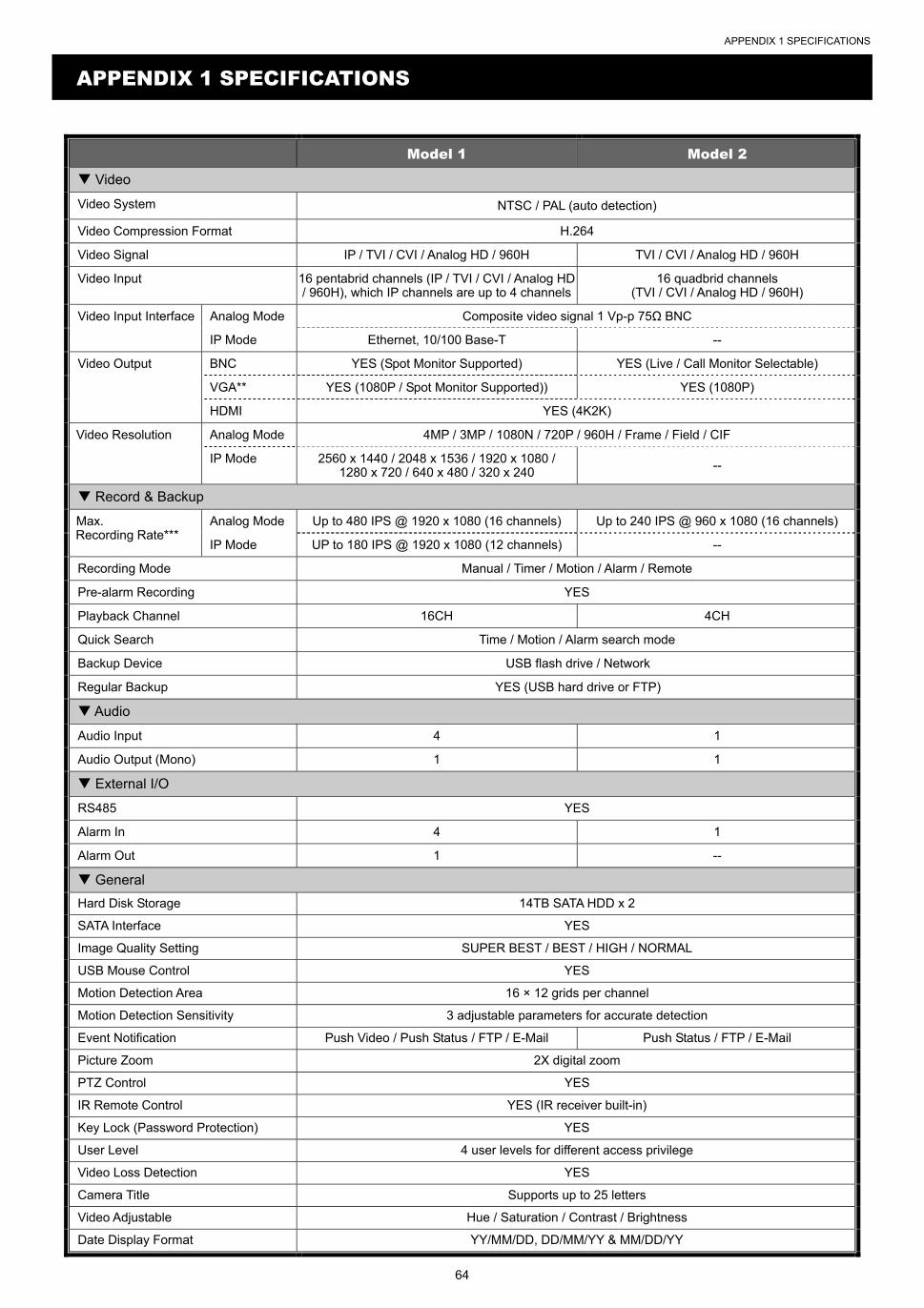
APPENDIX 1 SPECIFICATIONS
64
APPENDIX 1 SPECIFICATIONS
Model 1 Model 2
Video
Video System NTSC / PAL (auto detection)
Video Compression Format H.264
Video Signal IP / TVI / CVI / Analog HD / 960H TVI / CVI / Analog HD / 960H
Video Input 16 pentabrid channels (IP / TVI / CVI / Analog HD / 960H), which IP channels are up to 4 channels
16 quadbrid channels (TVI / CVI / Analog HD / 960H)
Video Input Interface Analog Mode Composite video signal 1 Vp-p 75Ω BNC
IP Mode Ethernet, 10/100 Base-T --
Video Output BNC YES (Spot Monitor Supported) YES (Live / Call Monitor Selectable)
VGA** YES (1080P / Spot Monitor Supported)) YES (1080P)
HDMI YES (4K2K)
Video Resolution Analog Mode 4MP / 3MP / 1080N / 720P / 960H / Frame / Field / CIF
IP Mode 2560 x 1440 / 2048 x 1536 / 1920 x 1080 / 1280 x 720 / 640 x 480 / 320 x 240 --
Record & Backup
Max. Recording Rate***
Analog Mode Up to 480 IPS @ 1920 x 1080 (16 channels) Up to 240 IPS @ 960 x 1080 (16 channels)
IP Mode UP to 180 IPS @ 1920 x 1080 (12 channels) --
Recording Mode Manual / Timer / Motion / Alarm / Remote
Pre-alarm Recording YES
Playback Channel 16CH 4CH
Quick Search Time / Motion / Alarm search mode
Backup Device USB flash drive / Network
Regular Backup YES (USB hard drive or FTP)
Audio
Audio Input 4 1
Audio Output (Mono) 1 1
External I/O
RS485 YES
Alarm In 4 1
Alarm Out 1 --
General
Hard Disk Storage 14TB SATA HDD x 2
SATA Interface YES
Image Quality Setting SUPER BEST / BEST / HIGH / NORMAL
USB Mouse Control YES
Motion Detection Area 16 × 12 grids per channel
Motion Detection Sensitivity 3 adjustable parameters for accurate detection
Event Notification Push Video / Push Status / FTP / E-Mail Push Status / FTP / E-Mail
Picture Zoom 2X digital zoom
PTZ Control YES
IR Remote Control YES (IR receiver built-in)
Key Lock (Password Protection) YES
User Level 4 user levels for different access privilege
Video Loss Detection YES
Camera Title Supports up to 25 letters
Video Adjustable Hue / Saturation / Contrast / Brightness
Date Display Format YY/MM/DD, DD/MM/YY & MM/DD/YY

APPENDIX 1 SPECIFICATIONS
65
Model 1 Model 2
General
Daylight Saving YES
Power Source (±10%) 19V / 3.42A 12V / 3A
Operating Temperature 10 ~ 40 (50~104)
Operating Humidity 10% ~ 85%
Dimensions (mm)**** 375(W) × 281 x 61 375 × 273.8 x 77
Net Weight (kg) 3.2 3.15
Network
Ethernet 10/100 Base-T. Supports remote control and live view via Ethernet
Network Protocol TCP/IP, PPPOE, DHCP and DDNS
Remote Surveillance from PC
Compatible Operating System Windows & MAC
Compatible Program Web Browser: Internet Explorer & Safari
CMS Lite: 32CH central management software for Windows OS
QuickTime: For both Windows and MAC operating systems
Max. online users 20
Web Transmitting Compression Format
H.264
Network Live Audio YES
Remote Event Download & Playback YES
Mobile Surveillance
App EagleEyes
Compatible Devices iOS & Android mobile devices
Push Video YES (16CH) --
Push Status YES
Others
EaZy Networking YES
IVA Support YES (4 channels in analog mode) --
Spot Monitor Support YES (VGA & Composite) --
DCCS Support YES
Free DDNS service YES
Privacy Mask YES
Multiplex Operation Live display / record / playback / backup / network operations
System Recovery System auto recovery after power failure
Optional Peripherals HDMI Matrix (HDM02) / USB Joystick (AVX102)
* The specifications are subject to change without notice.
** For 4K2K is chosen for HDMI output, VGA output is disabled.
*** For video recording, the resolution is up to 1080P even when the camera you’re using is a 3MP or 4MP camera.
**** Dimensional tolerance: ±5mm
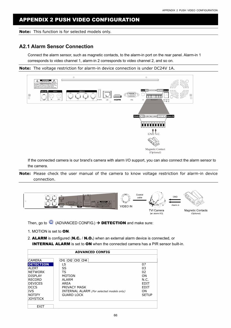
APPENDIX 2 PUSH VIDEO CONFIGURATION
66
APPENDIX 2 PUSH VIDEO CONFIGURATION
Note: This function is for selected models only.
A2.1 Alarm Sensor Connection
Connect the alarm sensor, such as magnetic contacts, to the alarm-in port on the rear panel. Alarm-in 1
corresponds to video channel 1, alarm-in 2 corresponds to video channel 2, and so on.
Note: The voltage restriction for alarm-in device connection is under DC24V 1A.
If the connected camera is our brand’s camera with alarm I/O support, you can also connect the alarm sensor to
the camera.
Note: Please check the user manual of the camera to know voltage restriction for alarm-in device connection.
Then, go to (ADVANCED CONFIG.) DETECTION and make sure:
1. MOTION is set to ON.
2. ALARM is configured (N.C. / N.O.) when an external alarm device is connected, or
INTERNAL ALARM is set to ON when the connected camera has a PIR sensor built-in.
ADVANCED CONFIG
CAMERA CH1 CH2 CH3 CH4 DETECTION LS 07 ALERT SS 03 NETWORK TS 02 DISPLAY MOTION ON RECORD ALARM N.C. DEVICES AREA EDIT DCCS PRIVACY MASK EDIT IVS INTERNAL ALARM (For selected models only) ON NOTIFY GUARD LOCK SETUP JOYSTICK
EXIT
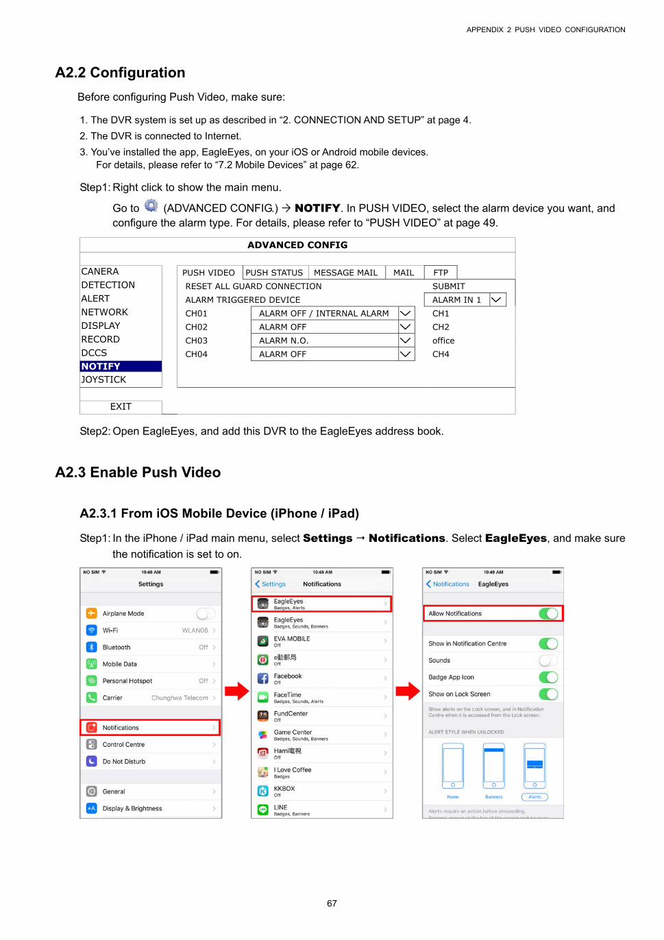
APPENDIX 2 PUSH VIDEO CONFIGURATION
67
A2.2 Configuration
Before configuring Push Video, make sure:
1. The DVR system is set up as described in “2. CONNECTION AND SETUP” at page 4.
2. The DVR is connected to Internet.
3. You’ve installed the app, EagleEyes, on your iOS or Android mobile devices. For details, please refer to “7.2 Mobile Devices” at page 62.
Step1: Right click to show the main menu.
Go to (ADVANCED CONFIG.) NOTIFY. In PUSH VIDEO, select the alarm device you want, and configure the alarm type. For details, please refer to “PUSH VIDEO” at page 49.
ADVANCED CONFIG
CANERA PUSH VIDEO PUSH STATUS MESSAGE MAIL MAIL FTP DETECTION RESET ALL GUARD CONNECTION SUBMIT ALERT ALARM TRIGGERED DEVICE ALARM IN 1 NETWORK CH01 ALARM OFF / INTERNAL ALARM CH1 DISPLAY CH02 ALARM OFF CH2 RECORD CH03 ALARM N.O. office DCCS CH04 ALARM OFF CH4 NOTIFY JOYSTICK
EXIT
Step2: Open EagleEyes, and add this DVR to the EagleEyes address book.
A2.3 Enable Push Video
A2.3.1 From iOS Mobile Device (iPhone / iPad)
Step1: In the iPhone / iPad main menu, select Settings Notifications. Select EagleEyes, and make sure
the notification is set to on.
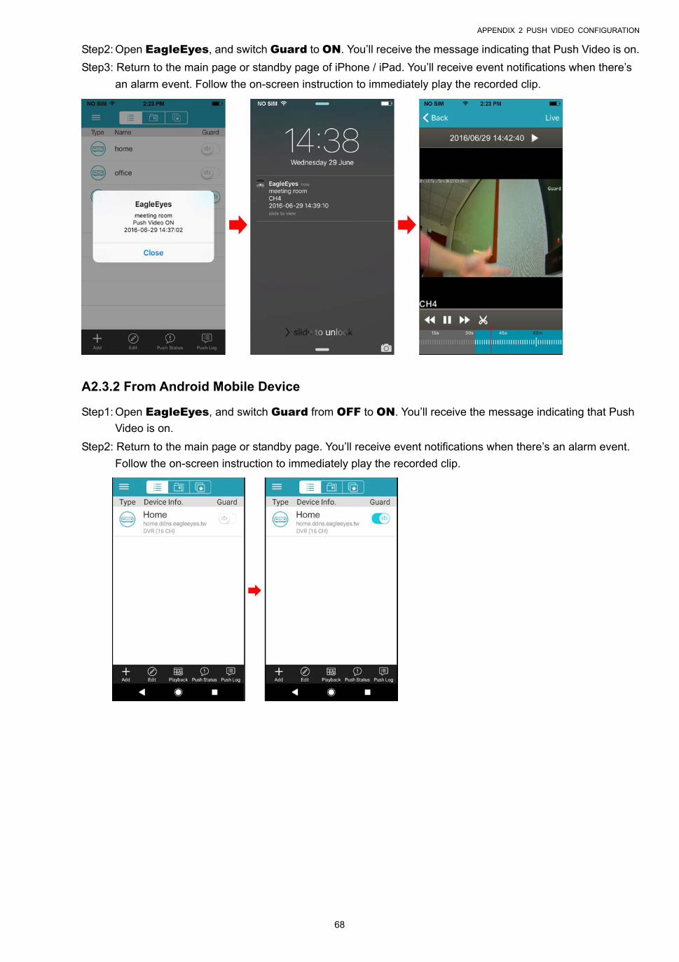
APPENDIX 2 PUSH VIDEO CONFIGURATION
68
Step2: Open EagleEyes, and switch Guard to ON. You’ll receive the message indicating that Push Video is on.
Step3: Return to the main page or standby page of iPhone / iPad. You’ll receive event notifications when there’s
an alarm event. Follow the on-screen instruction to immediately play the recorded clip.
A2.3.2 From Android Mobile Device
Step1: Open EagleEyes, and switch Guard from OFF to ON. You’ll receive the message indicating that Push
Video is on.
Step2: Return to the main page or standby page. You’ll receive event notifications when there’s an alarm event.
Follow the on-screen instruction to immediately play the recorded clip.
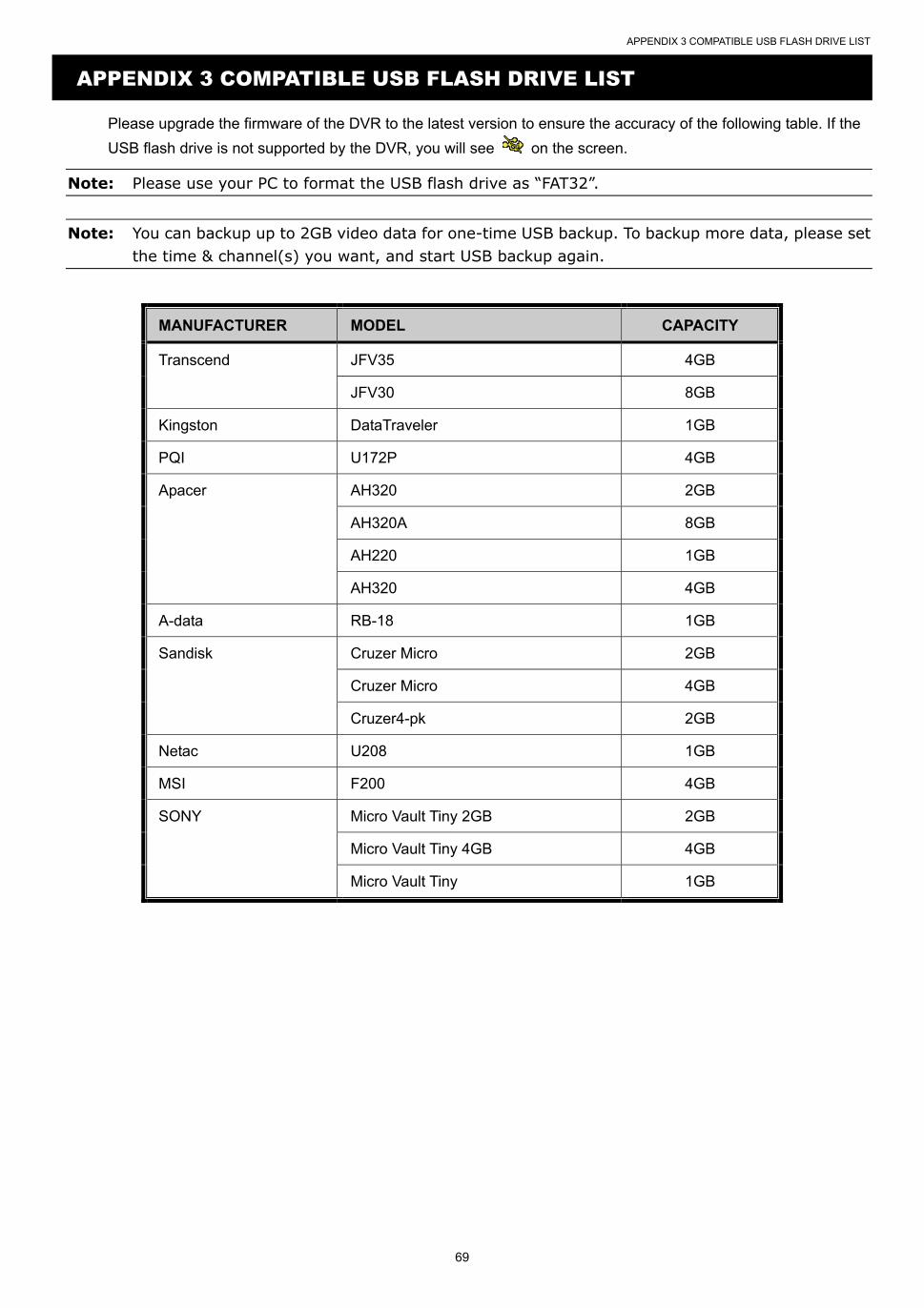
APPENDIX 3 COMPATIBLE USB FLASH DRIVE LIST
69
APPENDIX 3 COMPATIBLE USB FLASH DRIVE LIST
Please upgrade the firmware of the DVR to the latest version to ensure the accuracy of the following table. If the
USB flash drive is not supported by the DVR, you will see on the screen.
Note: Please use your PC to format the USB flash drive as “FAT32”.
Note: You can backup up to 2GB video data for one-time USB backup. To backup more data, please set the time & channel(s) you want, and start USB backup again.
MANUFACTURER MODEL CAPACITY
Transcend JFV35 4GB
JFV30 8GB
Kingston DataTraveler 1GB
PQI U172P 4GB
Apacer AH320 2GB
AH320A 8GB
AH220 1GB
AH320 4GB
A-data RB-18 1GB
Sandisk Cruzer Micro 2GB
Cruzer Micro 4GB
Cruzer4-pk 2GB
Netac U208 1GB
MSI F200 4GB
SONY Micro Vault Tiny 2GB 2GB
Micro Vault Tiny 4GB 4GB
Micro Vault Tiny 1GB
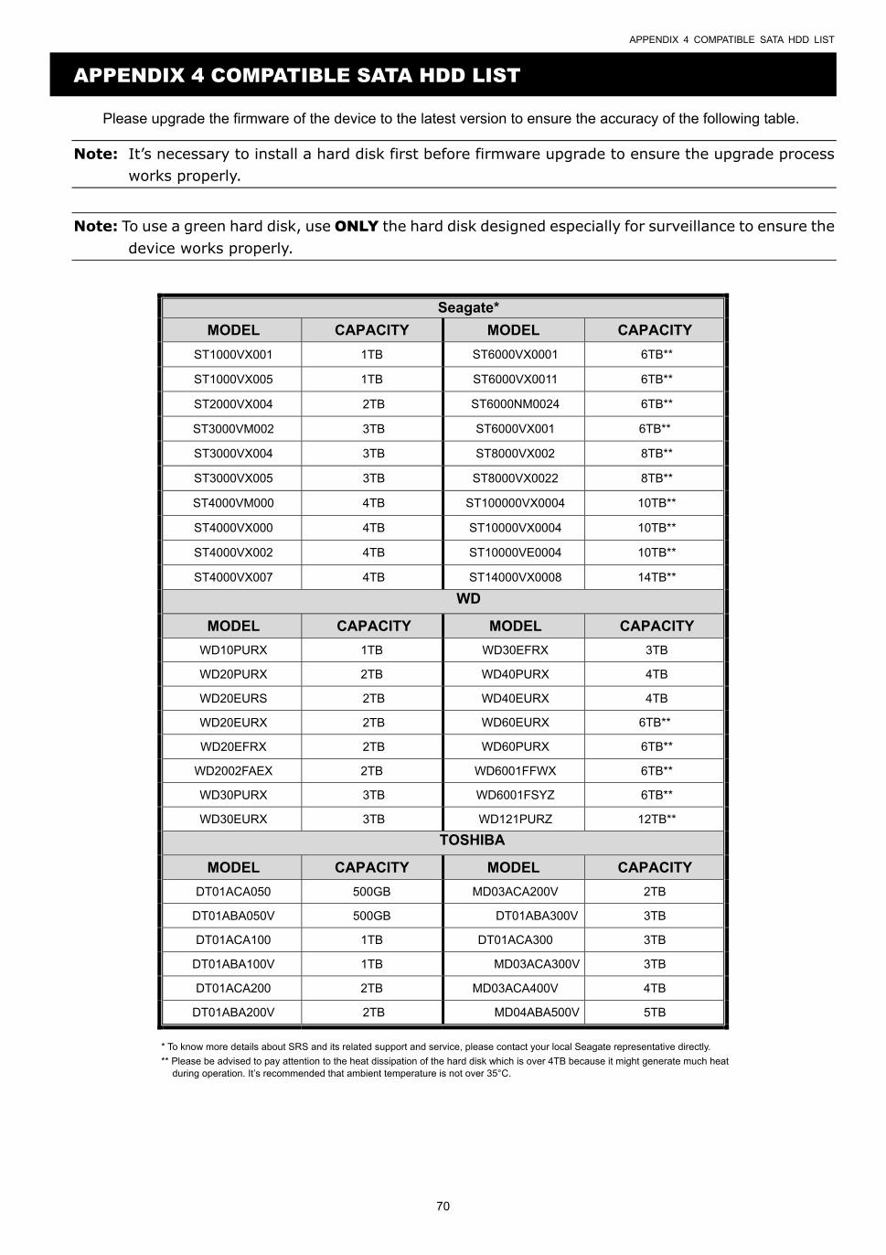
APPENDIX 4 COMPATIBLE SATA HDD LIST
70
APPENDIX 4 COMPATIBLE SATA HDD LIST
Please upgrade the firmware of the device to the latest version to ensure the accuracy of the following table.
Note: It’s necessary to install a hard disk first before firmware upgrade to ensure the upgrade process works properly.
Note: To use a green hard disk, use ONLY the hard disk designed especially for surveillance to ensure the device works properly.
Seagate*
MODEL CAPACITY MODEL CAPACITY
ST1000VX001 1TB ST6000VX0001 6TB**
ST1000VX005 1TB ST6000VX0011 6TB**
ST2000VX004 2TB ST6000NM0024 6TB**
ST3000VM002 3TB ST6000VX001 6TB**
ST3000VX004 3TB ST8000VX002 8TB**
ST3000VX005 3TB ST8000VX0022 8TB**
ST4000VM000 4TB ST100000VX0004 10TB**
ST4000VX000 4TB ST10000VX0004 10TB**
ST4000VX002 4TB ST10000VE0004 10TB**
ST4000VX007 4TB ST14000VX0008 14TB**
WD
MODEL CAPACITY MODEL CAPACITY
WD10PURX 1TB WD30EFRX 3TB
WD20PURX 2TB WD40PURX 4TB
WD20EURS 2TB WD40EURX 4TB
WD20EURX 2TB WD60EURX 6TB**
WD20EFRX 2TB WD60PURX 6TB**
WD2002FAEX 2TB WD6001FFWX 6TB**
WD30PURX 3TB WD6001FSYZ 6TB**
WD30EURX 3TB WD121PURZ 12TB**
TOSHIBA
MODEL CAPACITY MODEL CAPACITY
DT01ACA050 500GB MD03ACA200V 2TB
DT01ABA050V 500GB DT01ABA300V 3TB
DT01ACA100 1TB DT01ACA300 3TB
DT01ABA100V 1TB MD03ACA300V 3TB
DT01ACA200 2TB MD03ACA400V 4TB
DT01ABA200V 2TB MD04ABA500V 5TB
* To know more details about SRS and its related support and service, please contact your local Seagate representative directly.
** Please be advised to pay attention to the heat dissipation of the hard disk which is over 4TB because it might generate much heat during operation. It’s recommended that ambient temperature is not over 35°C.
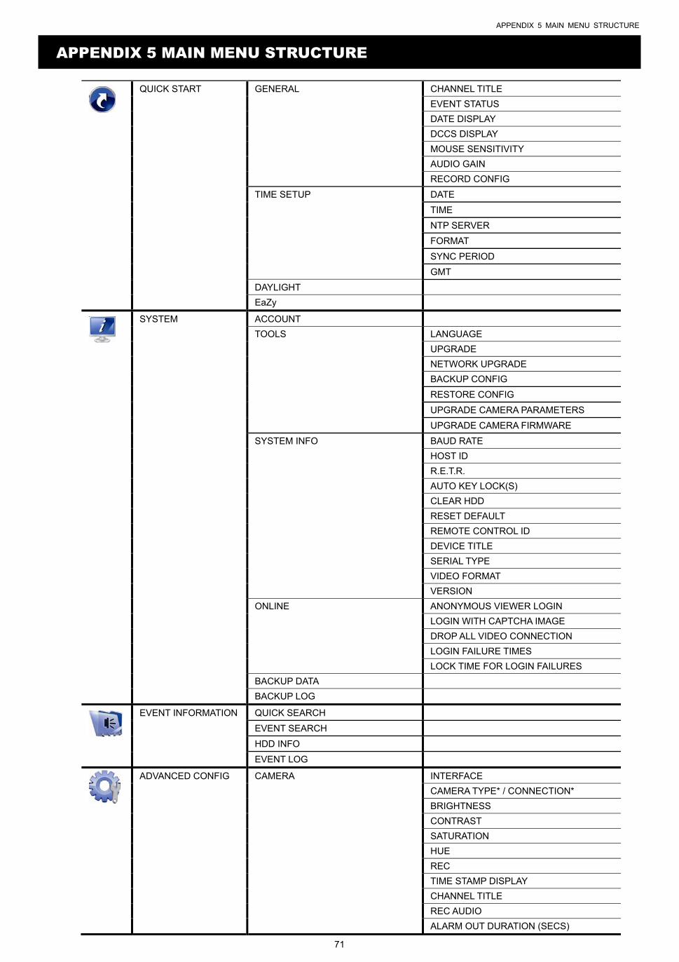
APPENDIX 5 MAIN MENU STRUCTURE
71
APPENDIX 5 MAIN MENU STRUCTURE
QUICK START GENERAL CHANNEL TITLE
EVENT STATUS
DATE DISPLAY
DCCS DISPLAY
MOUSE SENSITIVITY
AUDIO GAIN
RECORD CONFIG
TIME SETUP DATE
TIME
NTP SERVER
FORMAT
SYNC PERIOD
GMT
DAYLIGHT
EaZy
SYSTEM ACCOUNT
TOOLS LANGUAGE
UPGRADE
NETWORK UPGRADE
BACKUP CONFIG
RESTORE CONFIG
UPGRADE CAMERA PARAMETERS
UPGRADE CAMERA FIRMWARE
SYSTEM INFO BAUD RATE
HOST ID
R.E.T.R.
AUTO KEY LOCK(S)
CLEAR HDD
RESET DEFAULT
REMOTE CONTROL ID
DEVICE TITLE
SERIAL TYPE
VIDEO FORMAT
VERSION
ONLINE ANONYMOUS VIEWER LOGIN
LOGIN WITH CAPTCHA IMAGE
DROP ALL VIDEO CONNECTION
LOGIN FAILURE TIMES
LOCK TIME FOR LOGIN FAILURES
BACKUP DATA
BACKUP LOG
EVENT INFORMATION QUICK SEARCH
EVENT SEARCH
HDD INFO
EVENT LOG
ADVANCED CONFIG CAMERA INTERFACE
CAMERA TYPE* / CONNECTION*
BRIGHTNESS
CONTRAST
SATURATION
HUE
REC
TIME STAMP DISPLAY
CHANNEL TITLE
REC AUDIO
ALARM OUT DURATION (SECS)
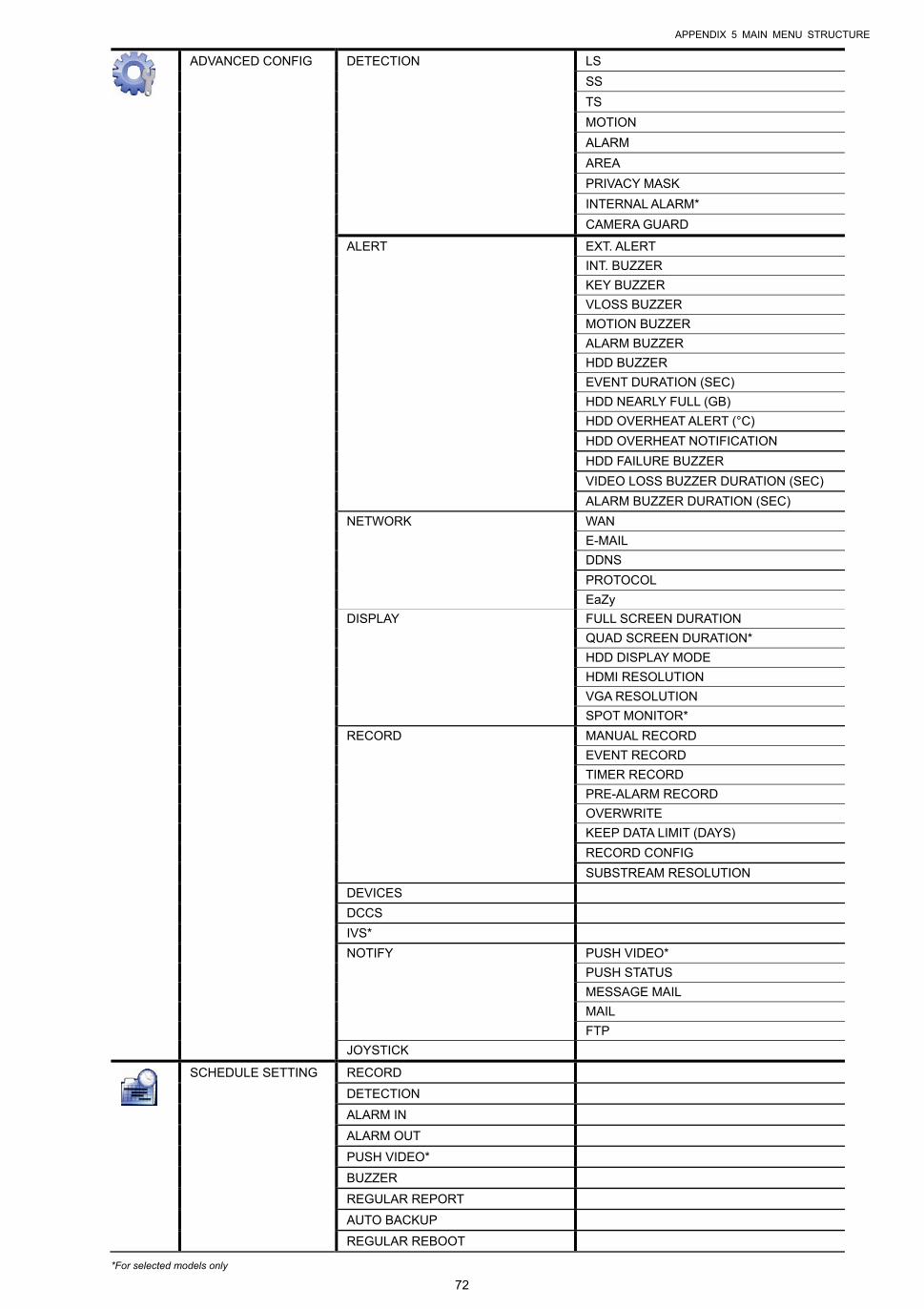
APPENDIX 5 MAIN MENU STRUCTURE
72
ADVANCED CONFIG DETECTION LS
SS
TS
MOTION
ALARM
AREA
PRIVACY MASK
INTERNAL ALARM*
CAMERA GUARD
ALERT EXT. ALERT
INT. BUZZER
KEY BUZZER
VLOSS BUZZER
MOTION BUZZER
ALARM BUZZER
HDD BUZZER
EVENT DURATION (SEC)
HDD NEARLY FULL (GB)
HDD OVERHEAT ALERT (°C)
HDD OVERHEAT NOTIFICATION
HDD FAILURE BUZZER
VIDEO LOSS BUZZER DURATION (SEC)
ALARM BUZZER DURATION (SEC)
NETWORK WAN
DDNS
PROTOCOL
EaZy
DISPLAY FULL SCREEN DURATION
QUAD SCREEN DURATION*
HDD DISPLAY MODE
HDMI RESOLUTION
VGA RESOLUTION
SPOT MONITOR*
RECORD MANUAL RECORD
EVENT RECORD
TIMER RECORD
PRE-ALARM RECORD
OVERWRITE
KEEP DATA LIMIT (DAYS)
RECORD CONFIG
SUBSTREAM RESOLUTION
DEVICES
DCCS
IVS*
NOTIFY PUSH VIDEO*
PUSH STATUS
MESSAGE MAIL
FTP
JOYSTICK
SCHEDULE SETTING RECORD
DETECTION
ALARM IN
ALARM OUT
PUSH VIDEO*
BUZZER
REGULAR REPORT
AUTO BACKUP
REGULAR REBOOT
*For selected models only

APPENDIX 6 DVR BATTERY REPLACEMENT
73
APPENDIX 6 DVR BATTERY REPLACEMENT
DVR time reset after power failure, for example, caused by a power outage, will cause the disorder of the recorded data,
and users may have problems in searching the event clip they want. To keep the DVR time from resetting, a
non-chargeable lithium battery, CR2032, is installed in the DVR.
However, the DVR time might still get reset when the DVR battery is low or even running out of power. If so, please
replace the DVR battery, CR2032, right away as instructed below.
How to replace CR2032
Note: The lithium battery, CR2032, is a non-chargeable battery, and should be purchased separately. Please replace only with the same or equivalent type battery in case of danger.
Step1: Stop all DVR recording immediately to prevent the disorder of the recorded data. Then, back up the
recorded data if necessary.
Step2: Power off the DVR, and disconnect the DVR power.
Step3: Remove the DVR cover, and find the battery on the mainboard.
Step4: Push the release as indicated below to remove the battery.
Step5: Get a new battery with the side of “CR2032” facing up, and install it to the mainboard.
Step6: Replace the DVR cover and connect to power.
Step7: Set DVR date & time, and resume recording. For details, please refer to “6.1.2 TIME SETUP” at page 25,
and “6.4.6 RECORD” at page 43.
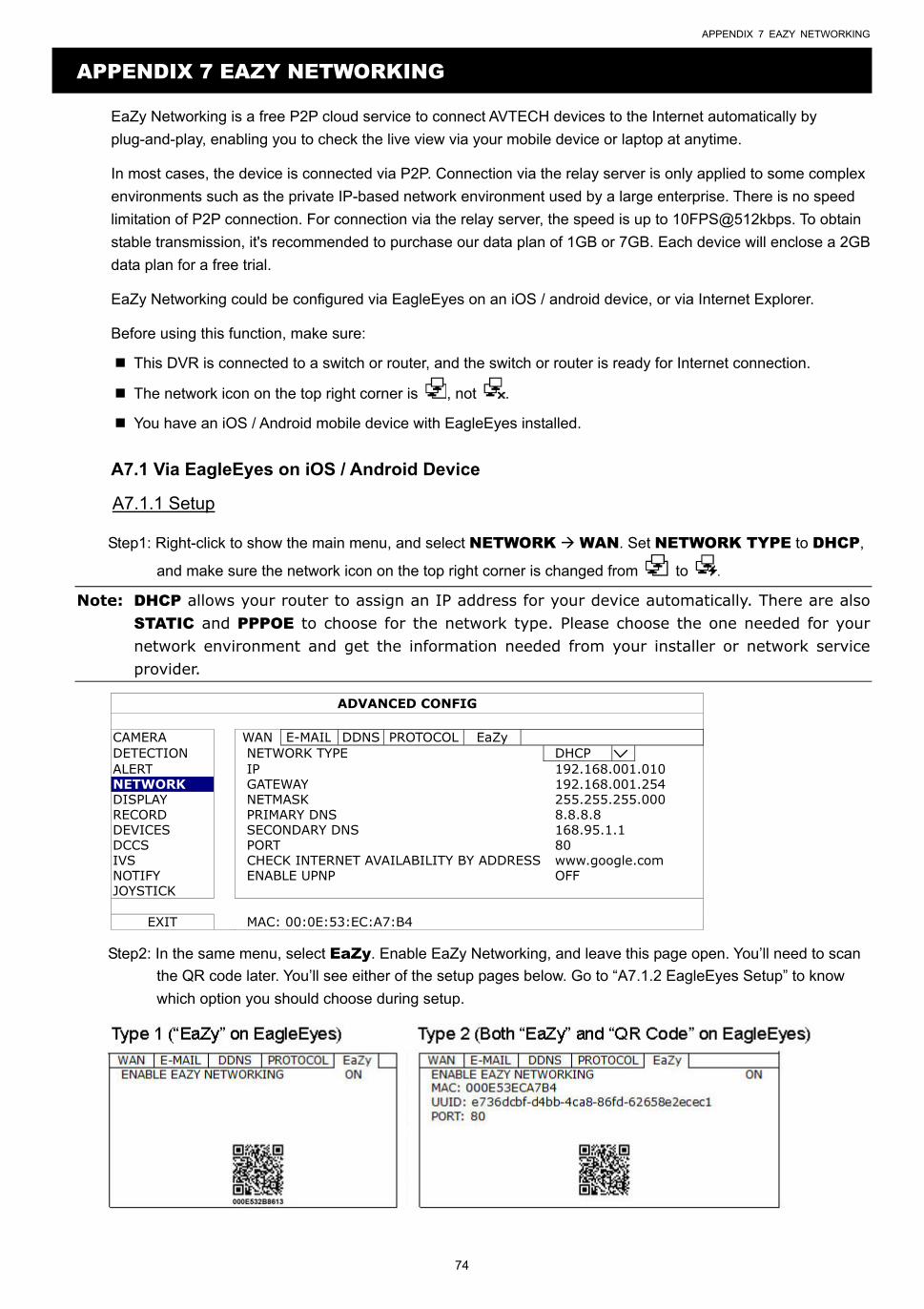
APPENDIX 7 EAZY NETWORKING
74
APPENDIX 7 EAZY NETWORKING
EaZy Networking is a free P2P cloud service to connect AVTECH devices to the Internet automatically by
plug-and-play, enabling you to check the live view via your mobile device or laptop at anytime.
In most cases, the device is connected via P2P. Connection via the relay server is only applied to some complex
environments such as the private IP-based network environment used by a large enterprise. There is no speed
limitation of P2P connection. For connection via the relay server, the speed is up to 10FPS@512kbps. To obtain
stable transmission, it's recommended to purchase our data plan of 1GB or 7GB. Each device will enclose a 2GB
data plan for a free trial.
EaZy Networking could be configured via EagleEyes on an iOS / android device, or via Internet Explorer.
Before using this function, make sure:
This DVR is connected to a switch or router, and the switch or router is ready for Internet connection.
The network icon on the top right corner is , not .
You have an iOS / Android mobile device with EagleEyes installed.
A7.1 Via EagleEyes on iOS / Android Device
A7.1.1 Setup
Step1: Right-click to show the main menu, and select NETWORK WAN. Set NETWORK TYPE to DHCP,
and make sure the network icon on the top right corner is changed from to .
Note: DHCP allows your router to assign an IP address for your device automatically. There are also STATIC and PPPOE to choose for the network type. Please choose the one needed for your network environment and get the information needed from your installer or network service provider.
ADVANCED CONFIG
CAMERA WAN E-MAIL DDNS PROTOCOL EaZy DETECTION NETWORK TYPE DHCP ALERT IP 192.168.001.010 NETWORK GATEWAY 192.168.001.254 DISPLAY NETMASK 255.255.255.000 RECORD PRIMARY DNS 8.8.8.8 DEVICES SECONDARY DNS 168.95.1.1 DCCS PORT 80 IVS CHECK INTERNET AVAILABILITY BY ADDRESS www.google.com NOTIFY ENABLE UPNP OFF JOYSTICK
EXIT MAC: 00:0E:53:EC:A7:B4
Step2: In the same menu, select EaZy. Enable EaZy Networking, and leave this page open. You’ll need to scan
the QR code later. You’ll see either of the setup pages below. Go to “A7.1.2 EagleEyes Setup” to know
which option you should choose during setup.
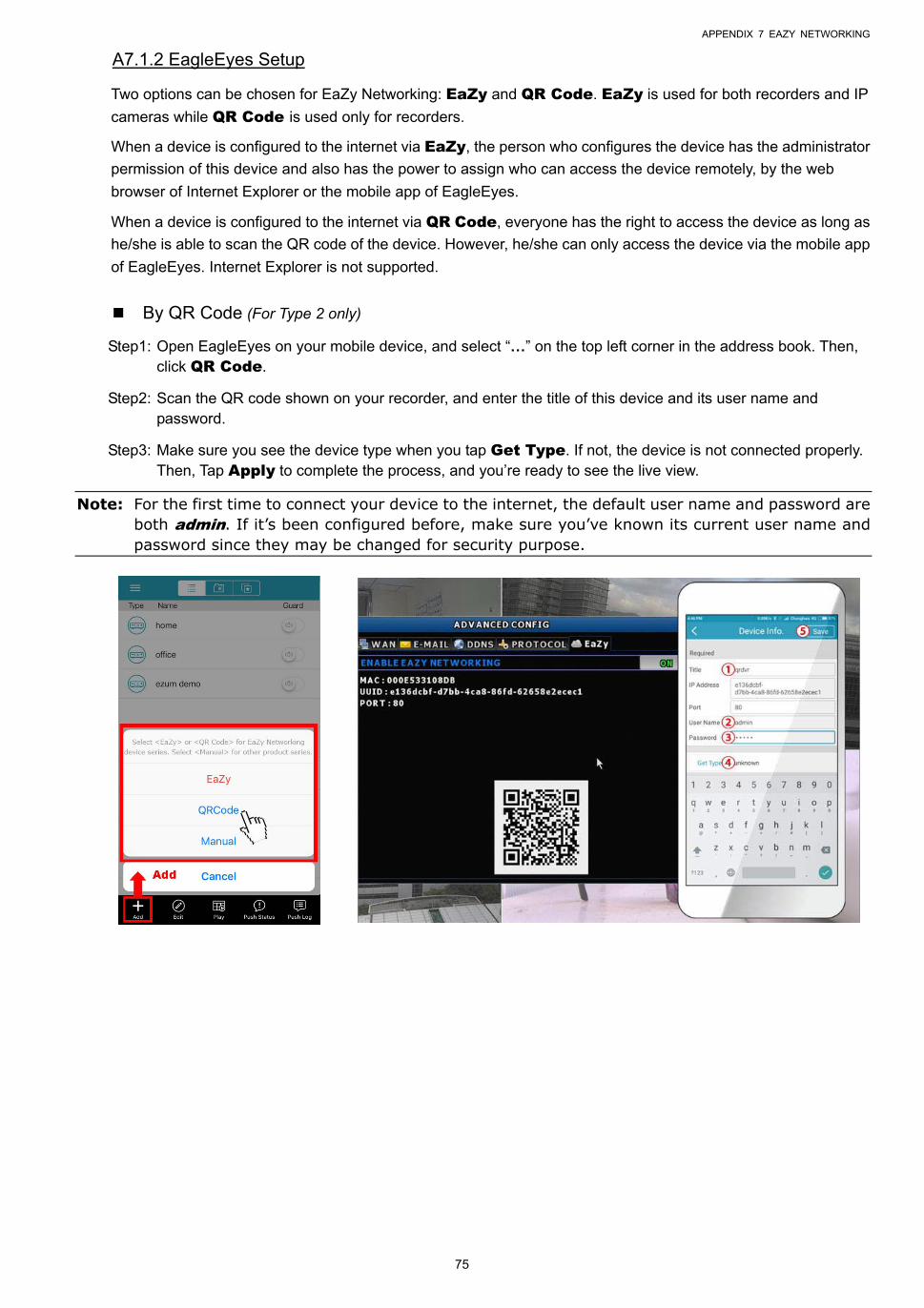
APPENDIX 7 EAZY NETWORKING
75
A7.1.2 EagleEyes Setup
Two options can be chosen for EaZy Networking: EaZy and QR Code. EaZy is used for both recorders and IP
cameras while QR Code is used only for recorders.
When a device is configured to the internet via EaZy, the person who configures the device has the administrator
permission of this device and also has the power to assign who can access the device remotely, by the web
browser of Internet Explorer or the mobile app of EagleEyes.
When a device is configured to the internet via QR Code, everyone has the right to access the device as long as
he/she is able to scan the QR code of the device. However, he/she can only access the device via the mobile app
of EagleEyes. Internet Explorer is not supported.
By QR Code (For Type 2 only)
Step1: Open EagleEyes on your mobile device, and select “…” on the top left corner in the address book. Then, click QR Code.
Step2: Scan the QR code shown on your recorder, and enter the title of this device and its user name and password.
Step3: Make sure you see the device type when you tap Get Type. If not, the device is not connected properly. Then, Tap Apply to complete the process, and you’re ready to see the live view.
Note: For the first time to connect your device to the internet, the default user name and password are both admin. If it’s been configured before, make sure you’ve known its current user name and password since they may be changed for security purpose.
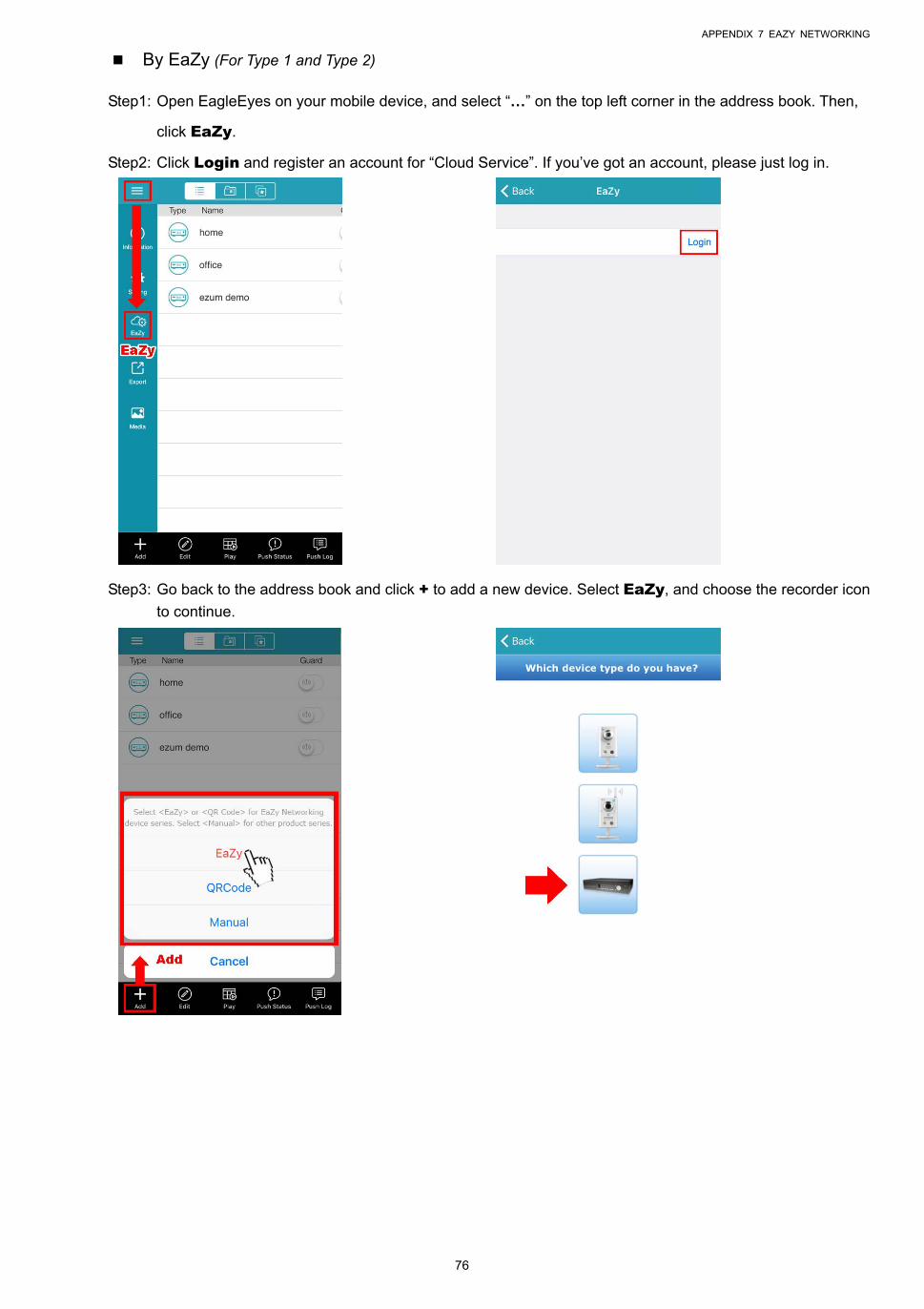
APPENDIX 7 EAZY NETWORKING
76
By EaZy (For Type 1 and Type 2)
Step1: Open EagleEyes on your mobile device, and select “…” on the top left corner in the address book. Then,
click EaZy.
Step2: Click Login and register an account for “Cloud Service”. If you’ve got an account, please just log in.
Step3: Go back to the address book and click + to add a new device. Select EaZy, and choose the recorder icon
to continue.
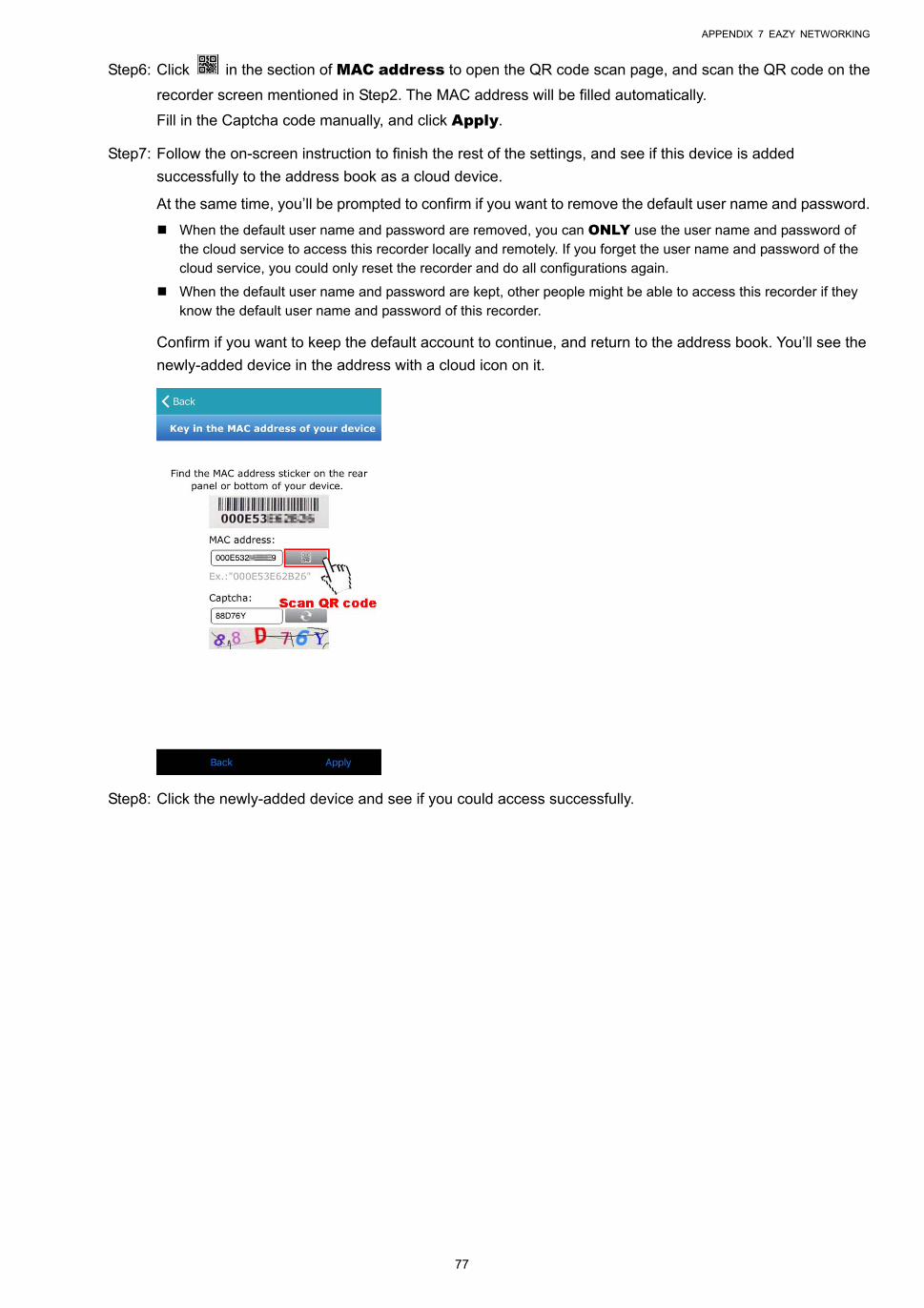
APPENDIX 7 EAZY NETWORKING
77
Step6: Click in the section of MAC address to open the QR code scan page, and scan the QR code on the
recorder screen mentioned in Step2. The MAC address will be filled automatically.
Fill in the Captcha code manually, and click Apply.
Step7: Follow the on-screen instruction to finish the rest of the settings, and see if this device is added
successfully to the address book as a cloud device.
At the same time, you’ll be prompted to confirm if you want to remove the default user name and password.
When the default user name and password are removed, you can ONLY use the user name and password of the cloud service to access this recorder locally and remotely. If you forget the user name and password of the cloud service, you could only reset the recorder and do all configurations again.
When the default user name and password are kept, other people might be able to access this recorder if they know the default user name and password of this recorder.
Confirm if you want to keep the default account to continue, and return to the address book. You’ll see the
newly-added device in the address with a cloud icon on it.
Step8: Click the newly-added device and see if you could access successfully.
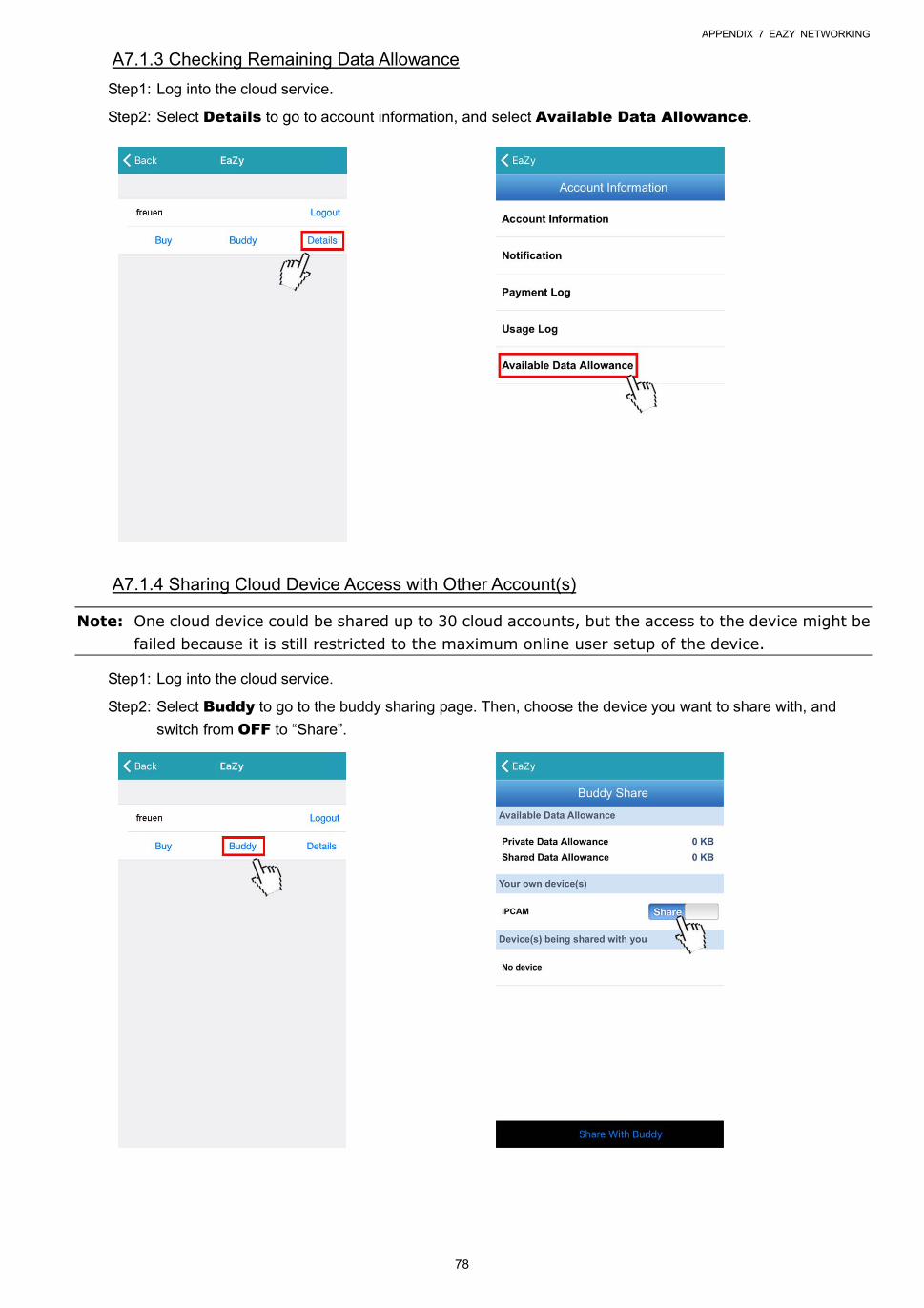
APPENDIX 7 EAZY NETWORKING
78
A7.1.3 Checking Remaining Data Allowance
Step1: Log into the cloud service.
Step2: Select Details to go to account information, and select Available Data Allowance.
A7.1.4 Sharing Cloud Device Access with Other Account(s)
Note: One cloud device could be shared up to 30 cloud accounts, but the access to the device might be failed because it is still restricted to the maximum online user setup of the device.
Step1: Log into the cloud service.
Step2: Select Buddy to go to the buddy sharing page. Then, choose the device you want to share with, and
switch from OFF to “Share”.
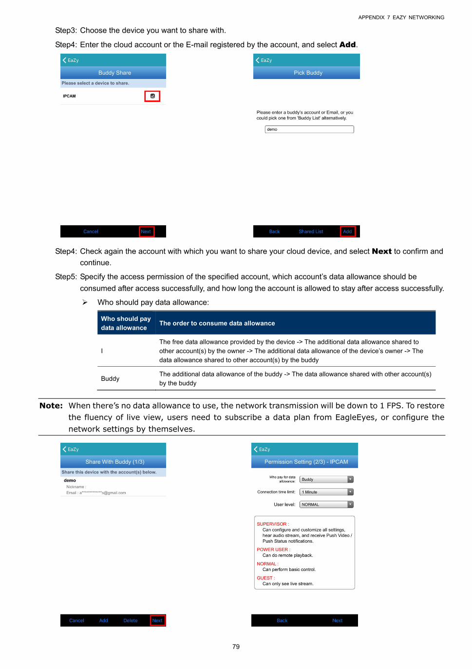
APPENDIX 7 EAZY NETWORKING
79
Step3: Choose the device you want to share with.
Step4: Enter the cloud account or the E-mail registered by the account, and select Add.
Step4: Check again the account with which you want to share your cloud device, and select Next to confirm and
continue.
Step5: Specify the access permission of the specified account, which account’s data allowance should be
consumed after access successfully, and how long the account is allowed to stay after access successfully.
Who should pay data allowance:
Who should pay
data allowance The order to consume data allowance
I
The free data allowance provided by the device -> The additional data allowance shared to
other account(s) by the owner -> The additional data allowance of the device’s owner -> The
data allowance shared to other account(s) by the buddy
Buddy The additional data allowance of the buddy -> The data allowance shared with other account(s)
by the buddy
Note: When there’s no data allowance to use, the network transmission will be down to 1 FPS. To restore the fluency of live view, users need to subscribe a data plan from EagleEyes, or configure the network settings by themselves.
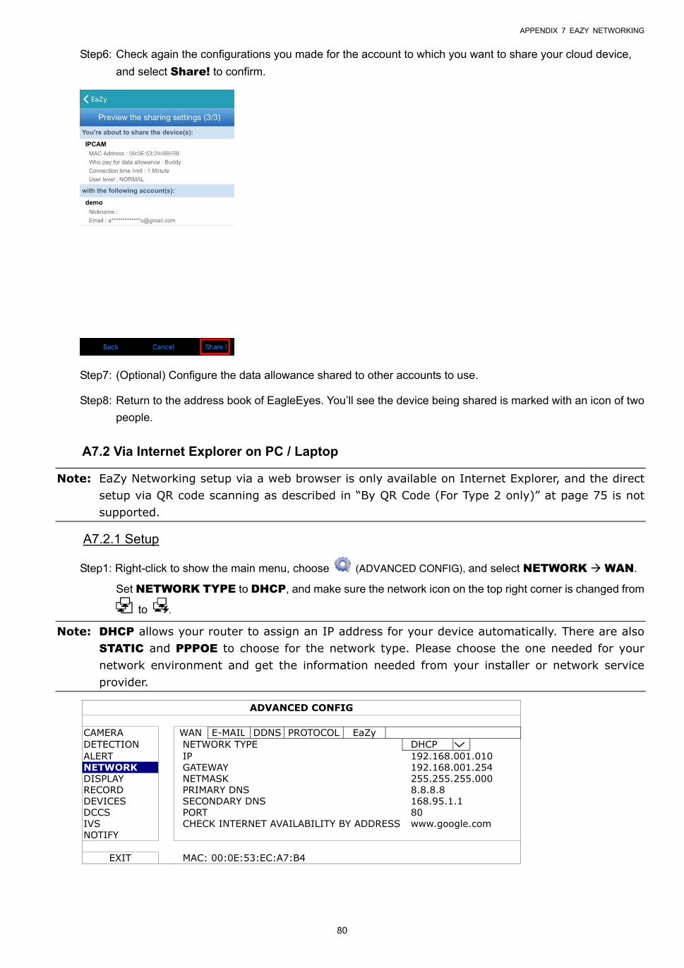
APPENDIX 7 EAZY NETWORKING
80
Step6: Check again the configurations you made for the account to which you want to share your cloud device,
and select Share! to confirm.
Step7: (Optional) Configure the data allowance shared to other accounts to use.
Step8: Return to the address book of EagleEyes. You’ll see the device being shared is marked with an icon of two
people.
A7.2 Via Internet Explorer on PC / Laptop
Note: EaZy Networking setup via a web browser is only available on Internet Explorer, and the direct setup via QR code scanning as described in “By QR Code (For Type 2 only)” at page 75 is not supported.
A7.2.1 Setup
Step1: Right-click to show the main menu, choose (ADVANCED CONFIG), and select NETWORK WAN.
Set NETWORK TYPE to DHCP, and make sure the network icon on the top right corner is changed from
to .
Note: DHCP allows your router to assign an IP address for your device automatically. There are also STATIC and PPPOE to choose for the network type. Please choose the one needed for your network environment and get the information needed from your installer or network service provider.
ADVANCED CONFIG
CAMERA WAN E-MAIL DDNS PROTOCOL EaZy DETECTION NETWORK TYPE DHCP ALERT IP 192.168.001.010 NETWORK GATEWAY 192.168.001.254 DISPLAY NETMASK 255.255.255.000 RECORD PRIMARY DNS 8.8.8.8 DEVICES SECONDARY DNS 168.95.1.1 DCCS PORT 80 IVS CHECK INTERNET AVAILABILITY BY ADDRESS www.google.com NOTIFY
EXIT MAC: 00:0E:53:EC:A7:B4
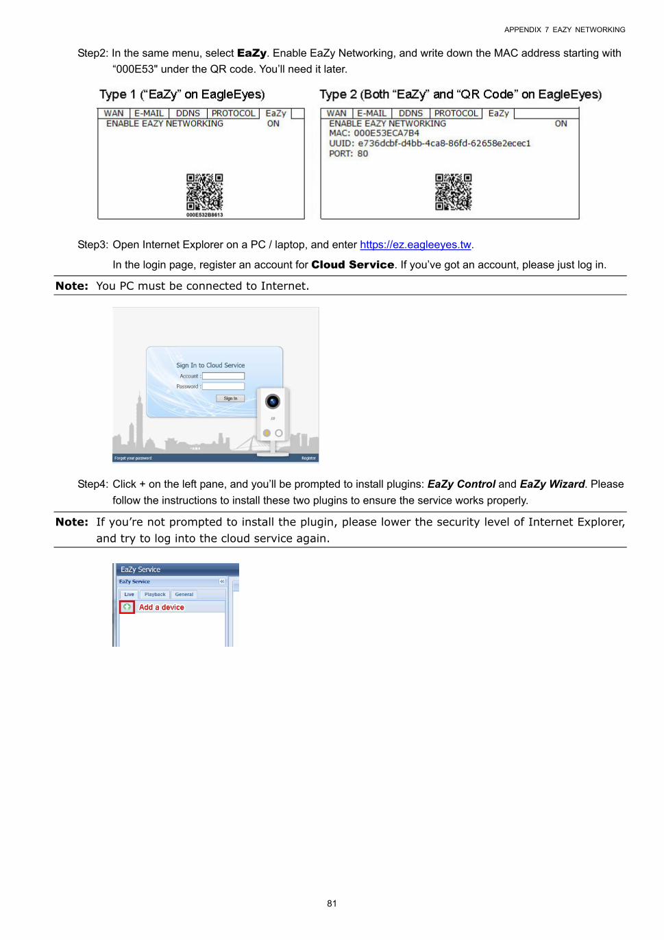
APPENDIX 7 EAZY NETWORKING
81
Step2: In the same menu, select EaZy. Enable EaZy Networking, and write down the MAC address starting with
“000E53" under the QR code. You’ll need it later.
Step3: Open Internet Explorer on a PC / laptop, and enter https://ez.eagleeyes.tw.
In the login page, register an account for Cloud Service. If you’ve got an account, please just log in.
Note: You PC must be connected to Internet.
Step4: Click + on the left pane, and you’ll be prompted to install plugins: EaZy Control and EaZy Wizard. Please
follow the instructions to install these two plugins to ensure the service works properly.
Note: If you’re not prompted to install the plugin, please lower the security level of Internet Explorer, and try to log into the cloud service again.
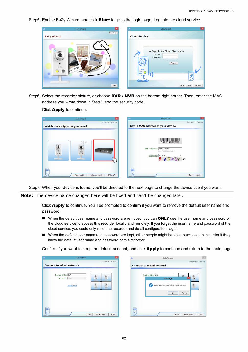
APPENDIX 7 EAZY NETWORKING
82
Step5: Enable EaZy Wizard, and click Start to go to the login page. Log into the cloud service.
Step6: Select the recorder picture, or choose DVR / NVR on the bottom right corner. Then, enter the MAC
address you wrote down in Step2, and the security code.
Click Apply to continue.
Step7: When your device is found, you’ll be directed to the next page to change the device title if you want.
Note: The device name changed here will be fixed and can’t be changed later.
Click Apply to continue. You’ll be prompted to confirm if you want to remove the default user name and
password.
When the default user name and password are removed, you can ONLY use the user name and password of the cloud service to access this recorder locally and remotely. If you forget the user name and password of the cloud service, you could only reset the recorder and do all configurations again.
When the default user name and password are kept, other people might be able to access this recorder if they know the default user name and password of this recorder.
Confirm if you want to keep the default account, and click Apply to continue and return to the main page.
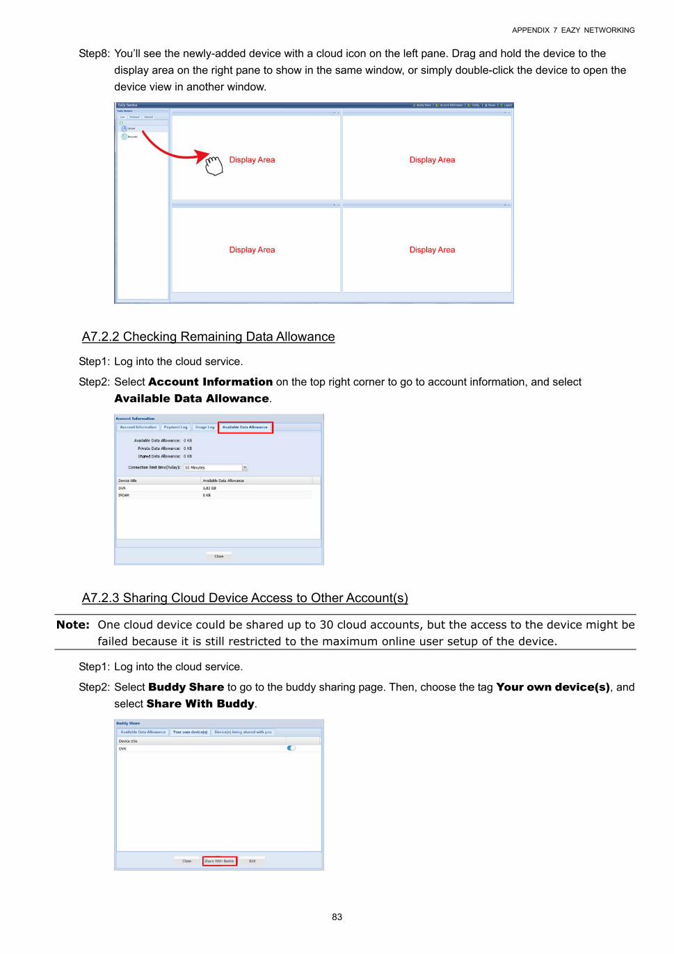
APPENDIX 7 EAZY NETWORKING
83
Step8: You’ll see the newly-added device with a cloud icon on the left pane. Drag and hold the device to the
display area on the right pane to show in the same window, or simply double-click the device to open the
device view in another window.
A7.2.2 Checking Remaining Data Allowance
Step1: Log into the cloud service.
Step2: Select Account Information on the top right corner to go to account information, and select
Available Data Allowance.
A7.2.3 Sharing Cloud Device Access to Other Account(s)
Note: One cloud device could be shared up to 30 cloud accounts, but the access to the device might be failed because it is still restricted to the maximum online user setup of the device.
Step1: Log into the cloud service.
Step2: Select Buddy Share to go to the buddy sharing page. Then, choose the tag Your own device(s), and
select Share With Buddy.
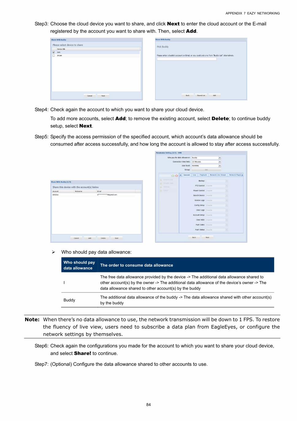
APPENDIX 7 EAZY NETWORKING
84
Step3: Choose the cloud device you want to share, and click Next to enter the cloud account or the E-mail
registered by the account you want to share with. Then, select Add.
Step4: Check again the account to which you want to share your cloud device.
To add more accounts, select Add; to remove the existing account, select Delete; to continue buddy
setup, select Next.
Step5: Specify the access permission of the specified account, which account’s data allowance should be
consumed after access successfully, and how long the account is allowed to stay after access successfully.
Who should pay data allowance:
Who should pay
data allowance The order to consume data allowance
I
The free data allowance provided by the device -> The additional data allowance shared to
other account(s) by the owner -> The additional data allowance of the device’s owner -> The
data allowance shared to other account(s) by the buddy
Buddy The additional data allowance of the buddy -> The data allowance shared with other account(s)
by the buddy
Note: When there’s no data allowance to use, the network transmission will be down to 1 FPS. To restore the fluency of live view, users need to subscribe a data plan from EagleEyes, or configure the network settings by themselves.
Step6: Check again the configurations you made for the account to which you want to share your cloud device,
and select Share! to continue.
Step7: (Optional) Configure the data allowance shared to other accounts to use.
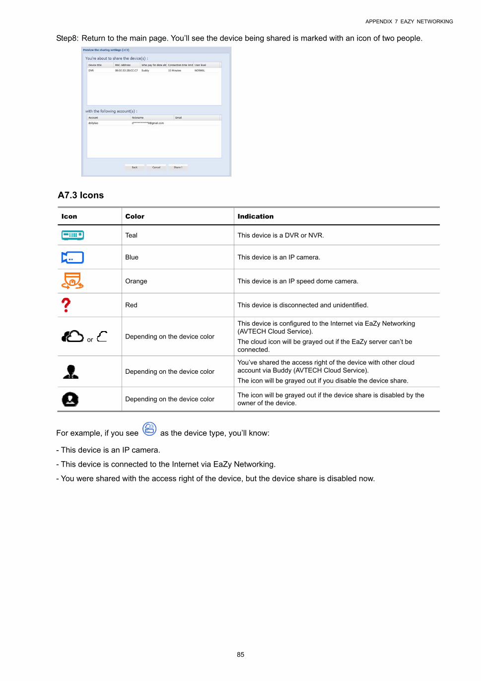
APPENDIX 7 EAZY NETWORKING
85
Step8: Return to the main page. You’ll see the device being shared is marked with an icon of two people.
A7.3 Icons
Icon Color Indication
Teal This device is a DVR or NVR.
Blue This device is an IP camera.
Orange This device is an IP speed dome camera.
Red This device is disconnected and unidentified.
or Depending on the device color
This device is configured to the Internet via EaZy Networking (AVTECH Cloud Service).
The cloud icon will be grayed out if the EaZy server can’t be connected.
Depending on the device color
You’ve shared the access right of the device with other cloud account via Buddy (AVTECH Cloud Service).
The icon will be grayed out if you disable the device share.
Depending on the device color
The icon will be grayed out if the device share is disabled by the owner of the device.
For example, if you see as the device type, you’ll know:
- This device is an IP camera.
- This device is connected to the Internet via EaZy Networking.
- You were shared with the access right of the device, but the device share is disabled now.