Embed Size (px)
Citation preview
HD Series
1NOVEMBER 2006
Signal Connector DIN 41612
• HDC and HDD interchangeable with DIN41612 C and D
• 0.6 mm and 1.0 mm Hypertac® contacts, in a two orthree row format
• Up to 192 positions
• HDT style offers mixed arrangements with signal,power and up to 12 co-axial contacts
• Accessories include Double Eurocard aligners andplastic covers
• HDD Style up to 32 heavy duty 1.0 mm contacts plusa maximum of 16 contacts 0.6 mm dia
Applicable Markets:Mil-Aero Space Marine
HD Series
2 NOVEMBER 2006
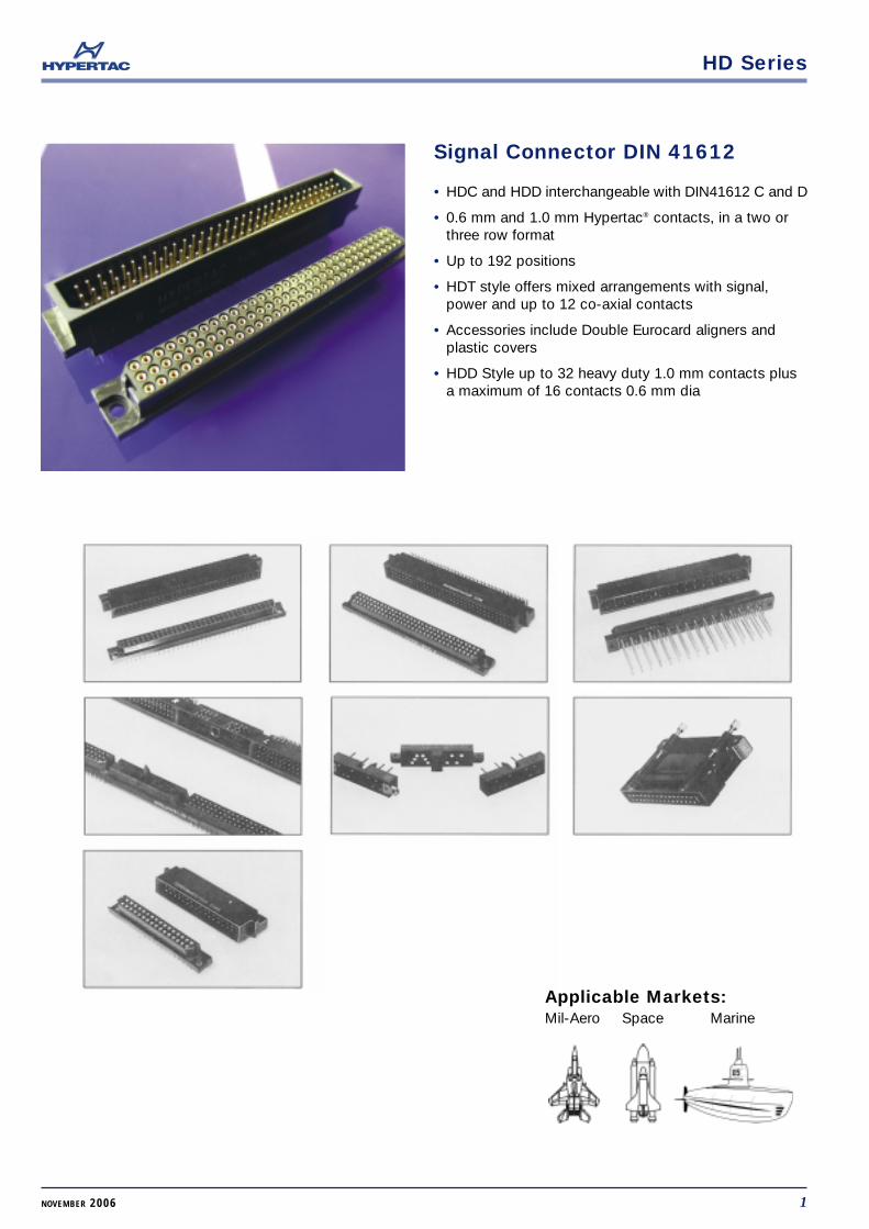
Front release/rear removable contacts
Contact insertion Contact removal
1 Assembly Tool Tweezer - NonFerrous
1 Extraction Tool HPD - 286 0.6mm male and female contactsand 1 mm male contact. HD240 1 mm female contact
2 Holding main body of extractiontool, align above contact cavityon mating face of insulator
3 Insert tubular tip fully, insuringthat tool remains in line with thecontact cavity. To avoid dama-ge, do not rotate or exert side-ways movement. This will retractcontact retention clip ears fromengagement with the shoulder inthe contact cavity
4 With the tool held fully inserted,depress handle. This will ejectthe contact out of the rear of theinsulator
2 Pick up contact with tweezer,align flats on contact with flats ininsulator
3 Insert contact into insulator in-suring flats are correctly aligned
4 Push contact fully into insulatorand insure that contact shoulderis 0.15 mm mimimum below insu-lator face. This will insure thecontact retention clips ears springout and engage behind the shoul-der inside the contact cavity. Agentle pull - not exceeding 18N(4.0 lb) will check for correct in-stallation
HD Series
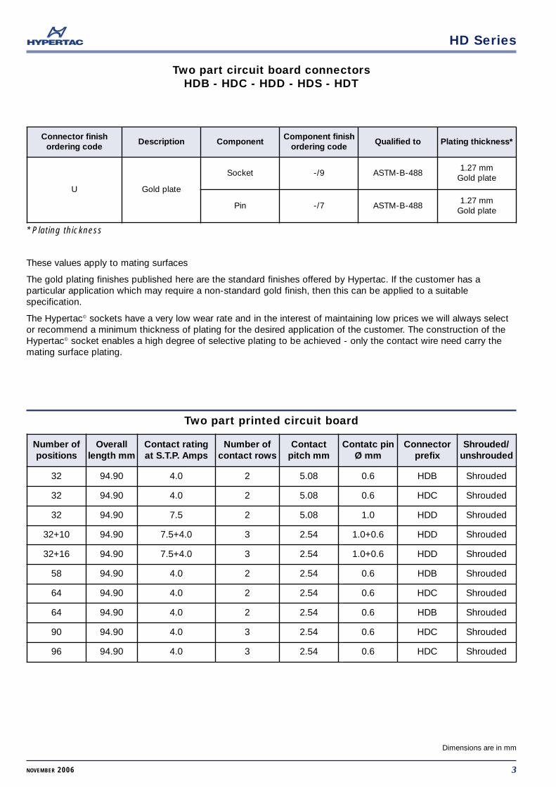
Two part circuit board connectorsHDB - HDC - HDD - HDS - HDT
3NOVEMBER 2006
Dimensions are in mm
Connector finishordering code
Description ComponentComponent finish
ordering codeQualified to Plating thickness*
U Gold plate
Socket -/9 ASTM-B-4881.27 mm
Gold plate
Pin -/7 ASTM-B-4881.27 mm
Gold plate
These values apply to mating surfaces
The gold plating finishes published here are the standard finishes offered by Hypertac. If the customer has aparticular application which may require a non-standard gold finish, then this can be applied to a suitablespecification.
The Hypertac© sockets have a very low wear rate and in the interest of maintaining low prices we will always selector recommend a minimum thickness of plating for the desired application of the customer. The construction of theHypertac© socket enables a high degree of selective plating to be achieved - only the contact wire need carry themating surface plating.
* Plating thickness
Number ofpositions
Overalllength mm
Contact ratingat S.T.P. Amps
Number ofcontact rows
Contactpitch mm
Contatc pinØ mm
Connectorprefix
Shrouded/unshrouded
32 94.90 4.0 2 5.08 0.6 HDB Shrouded
32 94.90 4.0 2 5.08 0.6 HDC Shrouded
32 94.90 7.5 2 5.08 1.0 HDD Shrouded
32+10 94.90 7.5+4.0 3 2.54 1.0+0.6 HDD Shrouded
32+16 94.90 7.5+4.0 3 2.54 1.0+0.6 HDD Shrouded
58 94.90 4.0 2 2.54 0.6 HDB Shrouded
64 94.90 4.0 2 2.54 0.6 HDC Shrouded
64 94.90 4.0 2 2.54 0.6 HDB Shrouded
90 94.90 4.0 3 2.54 0.6 HDC Shrouded
96 94.90 4.0 3 2.54 0.6 HDC Shrouded
Two part printed circuit board
HD Series
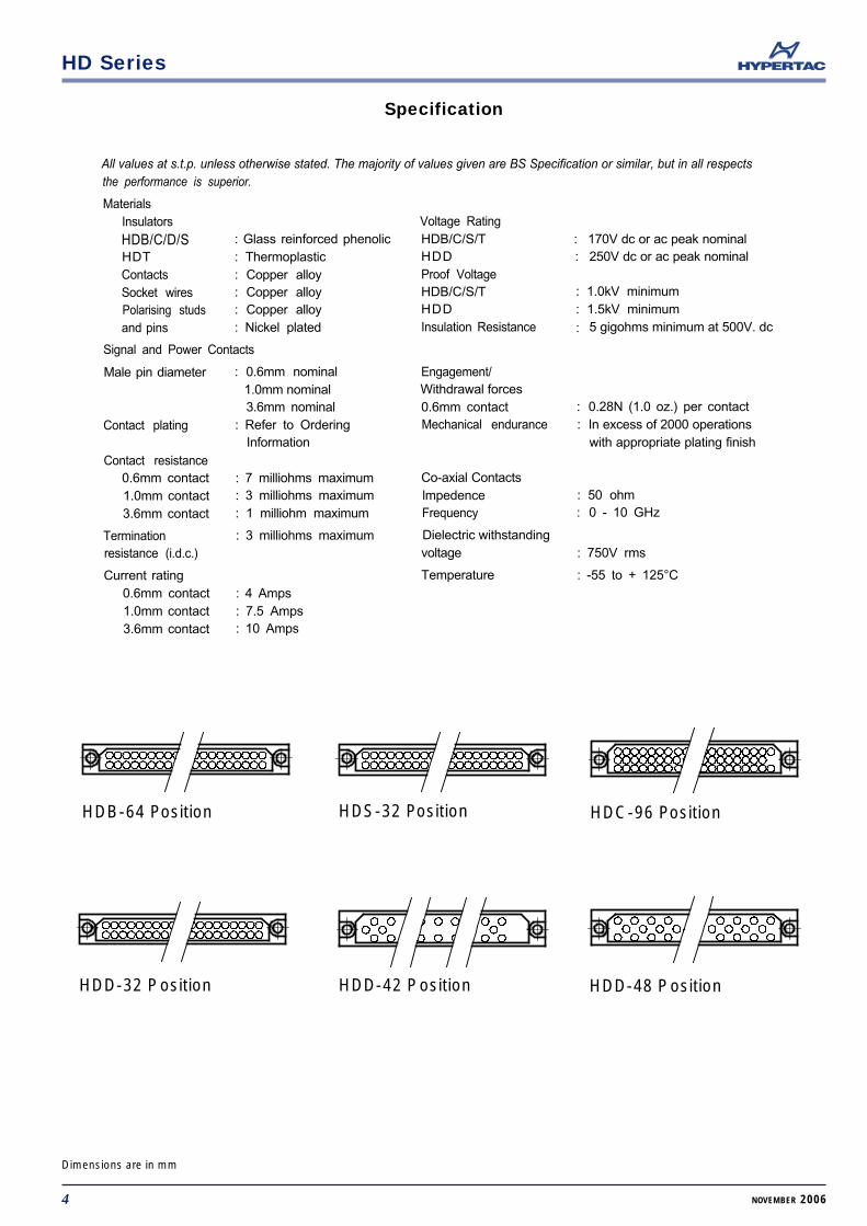
All values at s.t.p. unless otherwise stated. The majority of values given are BS Specification or similar, but in all respectsthe performance is superior.
MaterialsInsulators
HDB/C/D/S : Glass reinforced phenolicHDT : ThermoplasticContacts : Copper alloySocket wires : Copper alloyPolarising studs : Copper alloyand pins : Nickel plated
Signal and Power Contacts
Male pin diameter : 0.6mm nominal1.0mm nominal3.6mm nominal
Contact plating : Refer to OrderingInformation
Contact resistance0.6mm contact : 7 milliohms maximum1.0mm contact : 3 milliohms maximum3.6mm contact : 1 milliohm maximum
Termination : 3 milliohms maximumresistance (i.d.c.)
Current rating0.6mm contact : 4 Amps1.0mm contact : 7.5 Amps3.6mm contact : 10 Amps
Voltage RatingHDB/C/S/THDDProof VoltageHDB/C/S/THDDInsulation Resistance
Engagement/Withdrawal forces0.6mm contactMechanical endurance
Co-axial ContactslmpedenceFrequency
Dielectric withstandingvoltage
Temperature
: 170V dc or ac peak nominal: 250V dc or ac peak nominal
: 1.0kV minimum: 1.5kV minimum
: 5 gigohms minimum at 500V. dc
: 0.28N (1.0 oz.) per contact: In excess of 2000 operations
with appropriate plating finish
: 50 ohm: 0 - 10 GHz
: 750V rms
: -55 to + 125°C
HDB-64 Position HDS-32 Position HDC-96 Position
HDD-32 Position HDD-42 Position HDD-48 Position
Specification
4 NOVEMBER 2006
Dimensions are in mm
HD Series
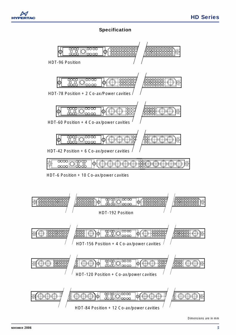
HDT-96 Position
HDT-78 Position + 2 Co-ax/Power cavities
HDT-60 Position + 4 Co-ax/power cavities
HDT-42 Position + 6 Co-ax/power cavities
HDT-6 Position + 10 Co-ax/power cavities
HDT-192 Position
HDT-156 Position + 4 Co-ax/power cavities
HDT-120 Position + Co-ax/power cavities
HDT-84 Position + 12 Co-ax/power cavities
Specification
5NOVEMBER 2006
Dimensions are in mm
HD Series
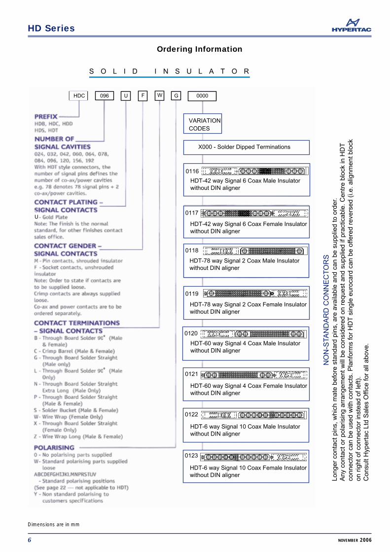
S O L I D I N S U L A T O R
0116
HDT-42 way Signal 6 Coax Male Insulatorwithout DIN aligner
0117
HDT-42 way Signal 6 Coax Female Insulatorwithout DIN aligner
0118
HDT-78 way Signal 2 Coax Male Insulatorwithout DIN aligner
0119
HDT-78 way Signal 2 Coax Female Insulatorwithout DIN aligner
0120
HDT-60 way Signal 4 Coax Male Insulatorwithout DIN aligner
0121
HDT-60 way Signal 4 Coax Female Insulatorwithout DIN aligner
0122
HDT-6 way Signal 10 Coax Male Insulatorwithout DIN aligner
0123
HDT-6 way Signal 10 Coax Female Insulatorwithout DIN aligner
X000 - Solder Dipped Terminations
VARIATIONCODES
U
HDC 096 U F W G 0000
°
°
Ordering Information
6 NOVEMBER 2006
Dimensions are in mm
NO
N-S
TAN
DA
RD
CO
NN
EC
TO
RS
Long
er c
onta
ct p
ins,
whi
ch m
ate
befo
re s
tand
ard
pins
, are
ava
ilabl
e an
d ca
n be
sup
plie
d to
ord
er.
Any
con
tact
or
pola
risin
g ar
rang
emen
t will
be
cons
ider
ed o
n re
ques
t and
sup
plie
d if
prac
ticab
le. C
entr
e bl
ock
in H
DT
conn
ecto
r ca
n be
use
d w
ith c
onta
cts.
Pla
nfor
ms
for
HD
Tsi
ngle
eur
ocar
d ca
n be
offe
red
reve
rsed
(i.e
. alig
nmen
t blo
ckon
rig
ht o
f con
nect
or in
stea
d of
left)
.C
onsu
lt H
yper
tac
Ltd
Sal
es O
ffice
for
all a
bove
.
HD Series
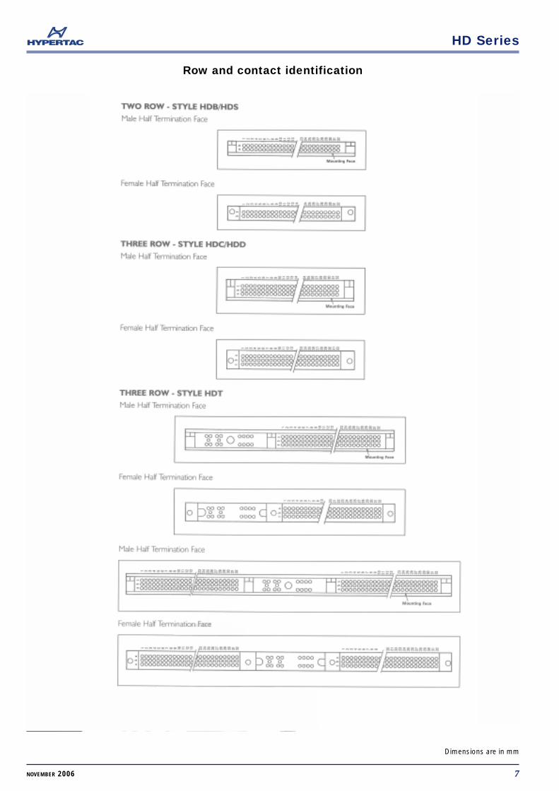
Row and contact identification
7NOVEMBER 2006
Dimensions are in mm
HD Series
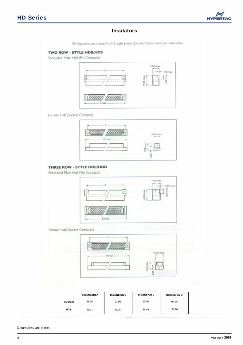
DIMENSION A DIMENSION B DIMENSION C DIMENSION D
HDB/C/D
HDS
88.90 93.90 90.00 94.90
48.31 53.26 49.46 54.26
Insulators
8 NOVEMBER 2006
Dimensions are in mm
HD Series
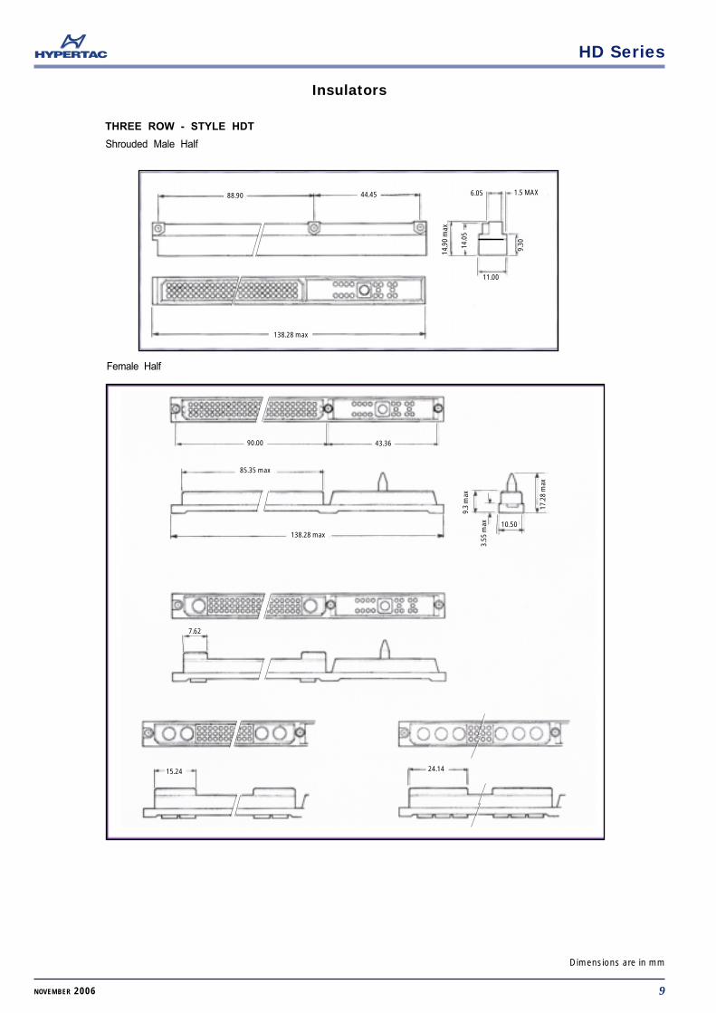
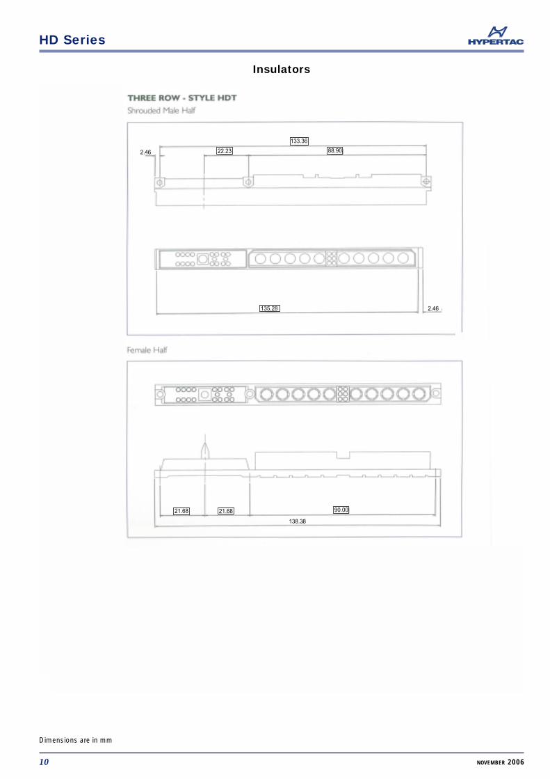
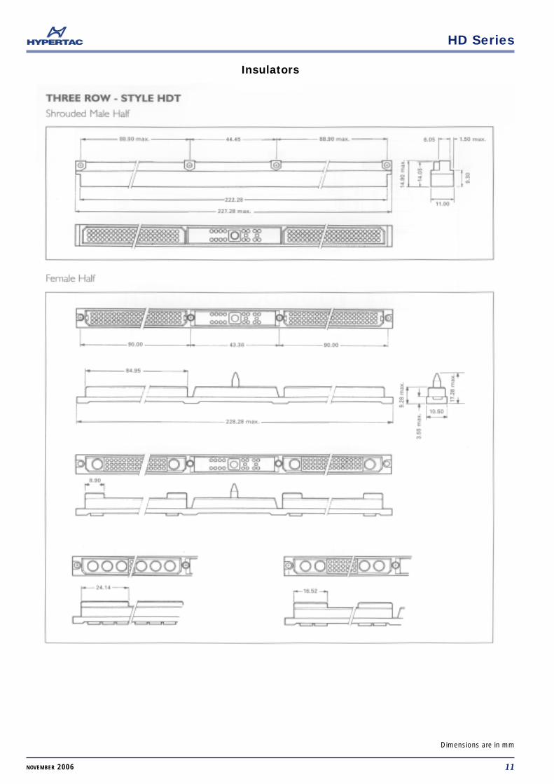
THREE ROW - STYLE HDT
Shrouded Male Half
Female Half
88.90 44.45
138.28 max
1.5 MAX6.05
11.00
14.9
0 m
ax
14.0
5
9.30
90.00 43.36
85.35 max
138.28 max17
.28
max
9.3
max
3.55
max 10.50
7.62
15.24 24.14
Insulators
9NOVEMBER 2006
Dimensions are in mm
HD Series
2.46 22.23
133.36
88.90
135.28
21.68 21.68 90.00
2.46
138.38
Insulators
10 NOVEMBER 2006
Dimensions are in mm
HD Series
Insulators
11NOVEMBER 2006
Dimensions are in mm
HD Series
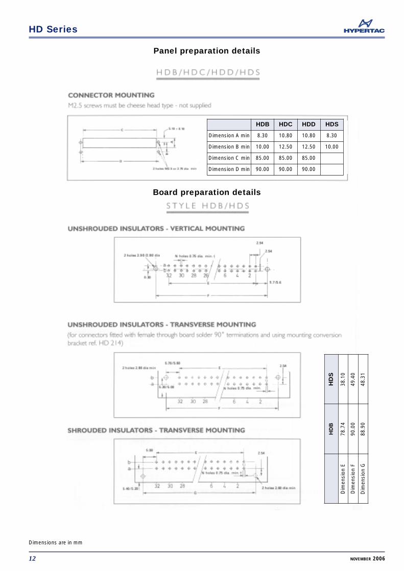
Panel preparation details
Board preparation details
12 NOVEMBER 2006
Dimensions are in mm
HDB HDC HDD HDS
Dimension A min 8.30 10.80 10.80 8.30
Dimension B min 10.00 12.50 12.50 10.00
Dimension C min 85.00 85.00 85.00
Dimension D min 90.00 90.00 90.00
HD
S
38.1
0
49.4
0
48.3
1
HD
B
78.7
4
90.0
0
88.9
0
Dim
ensi
on E
Dim
ensi
on F
Dim
ensi
on G
HD Series
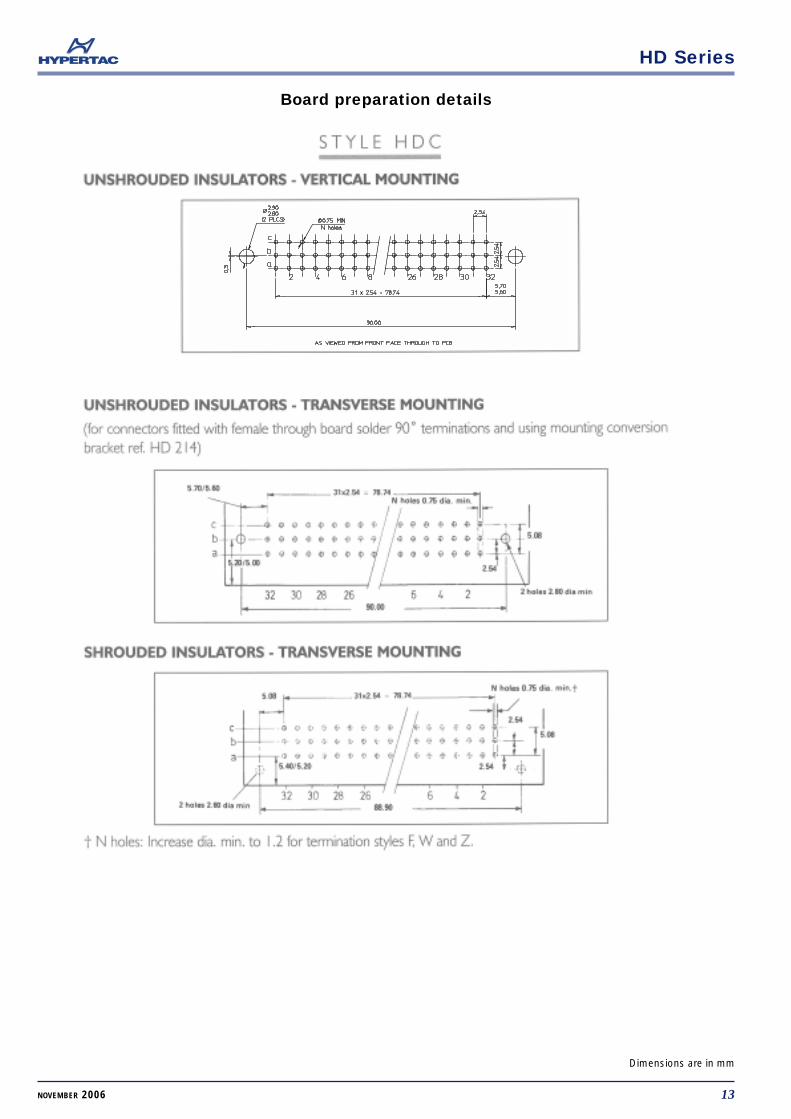
Board preparation details
13NOVEMBER 2006
Dimensions are in mm
HD Series
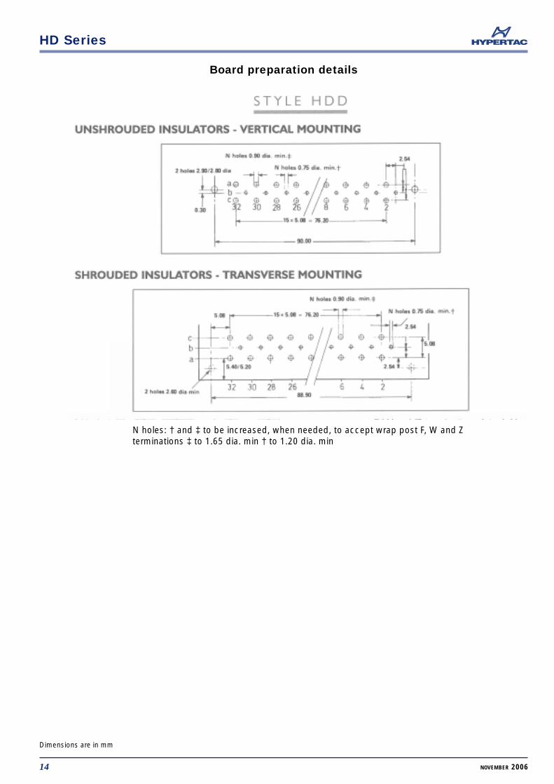
Board preparation details
14 NOVEMBER 2006
Dimensions are in mm
N holes: † and ‡ to be increased, when needed, to accept wrap post F, W and Zterminations ‡ to 1.65 dia. min † to 1.20 dia. min
HD Series
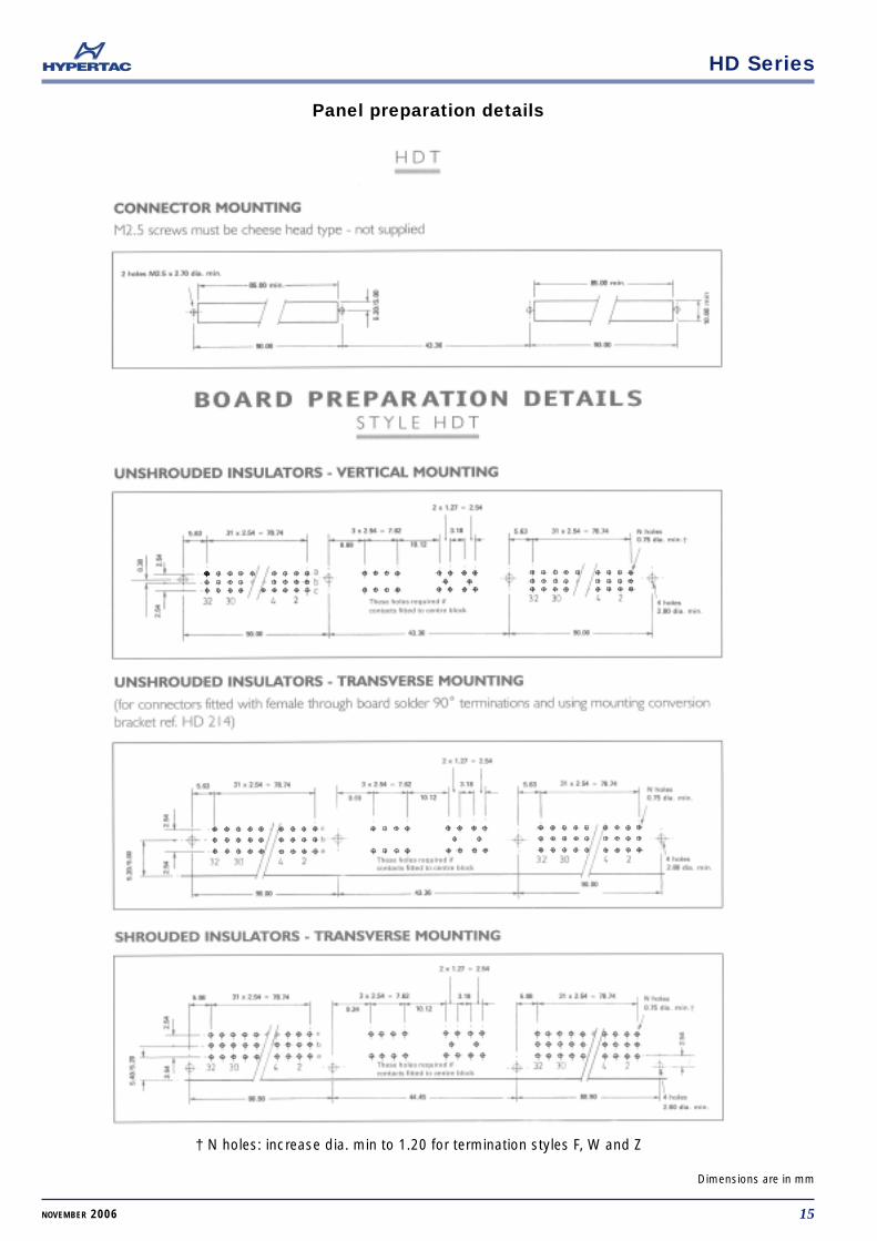
Panel preparation details
15NOVEMBER 2006
Dimensions are in mm
† N holes: increase dia. min to 1.20 for termination styles F, W and Z
HD Series
7
7 7
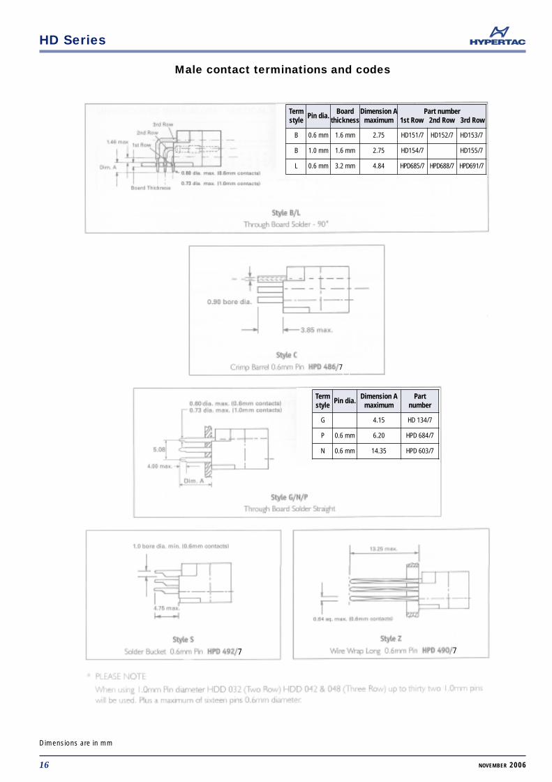
Male contact terminations and codes
16 NOVEMBER 2006
Dimensions are in mm
Termstyle
Pin dia.Board
thicknessDimension A
maximumPart number
1st Row 2nd Row 3rd Row
B 0.6 mm 1.6 mm 2.75 HD151/7 HD152/7 HD153/7
B 1.0 mm 1.6 mm 2.75 HD154/7 HD155/7
L 0.6 mm 3.2 mm 4.84 HPD685/7 HPD688/7 HPD691/7
Termstyle
Pin dia.Dimension A
maximumPart
number
G 4.15 HD 134/7
P 0.6 mm 6.20 HPD 684/7
N 0.6 mm 14.35 HPD 603/7
HD Series
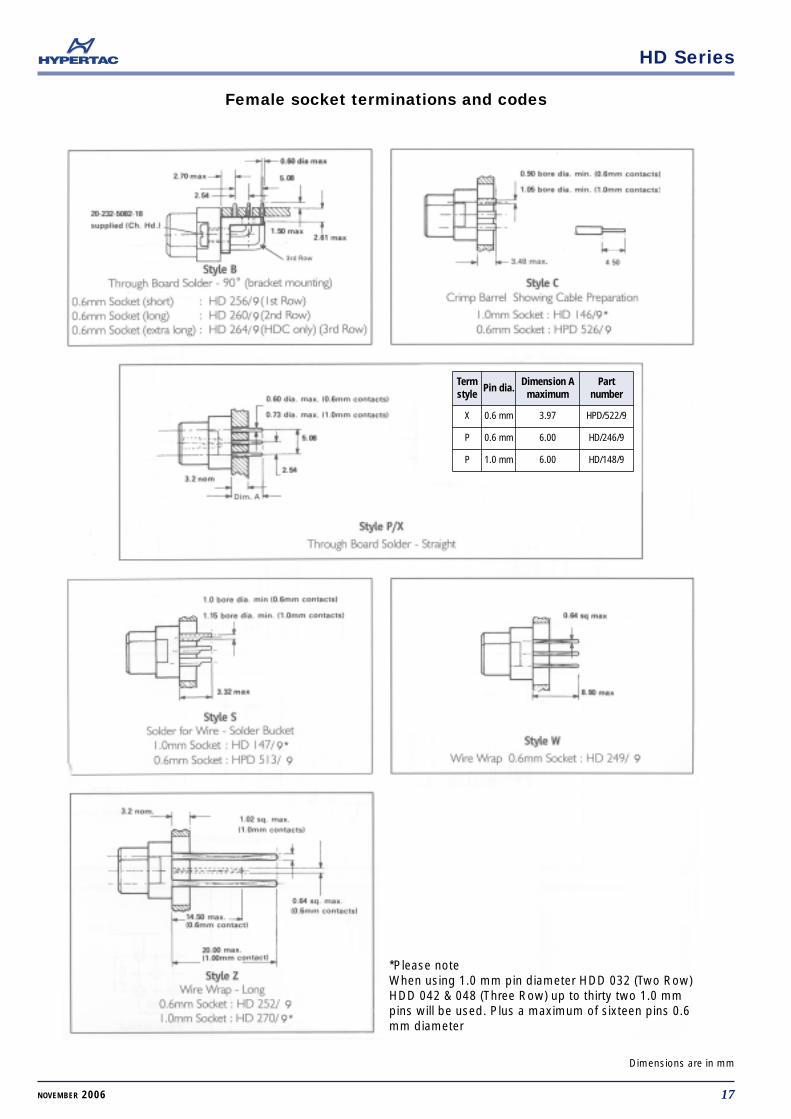
Female socket terminations and codes
17NOVEMBER 2006
Dimensions are in mm
Termstyle
Pin dia.Dimension A
maximumPart
number
X 0.6 mm 3.97 HPD/522/9
P 0.6 mm 6.00 HD/246/9
P 1.0 mm 6.00 HD/148/9
*Please noteWhen using 1.0 mm pin diameter HDD 032 (Two Row)HDD 042 & 048 (Three Row) up to thirty two 1.0 mmpins will be used. Plus a maximum of sixteen pins 0.6mm diameter
HD Series
18 NOVEMBER 2006
Dimensions are in mm
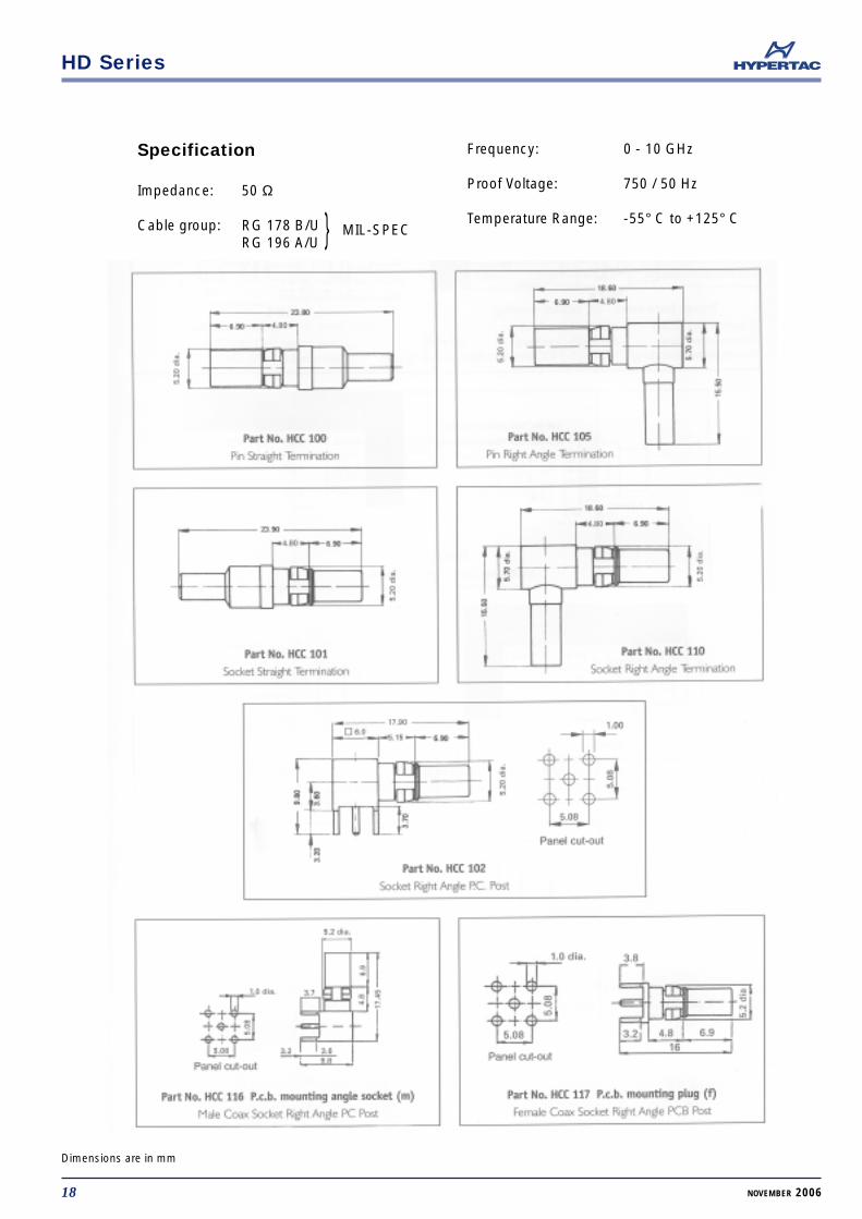
Specification
Impedance: 50 Ω
Cable group: RG 178 B/URG 196 A/U
Frequency: 0 - 10 GHz
Proof Voltage: 750 / 50 Hz
Temperature Range: -55° C to +125° C MIL-SPEC
HD Series
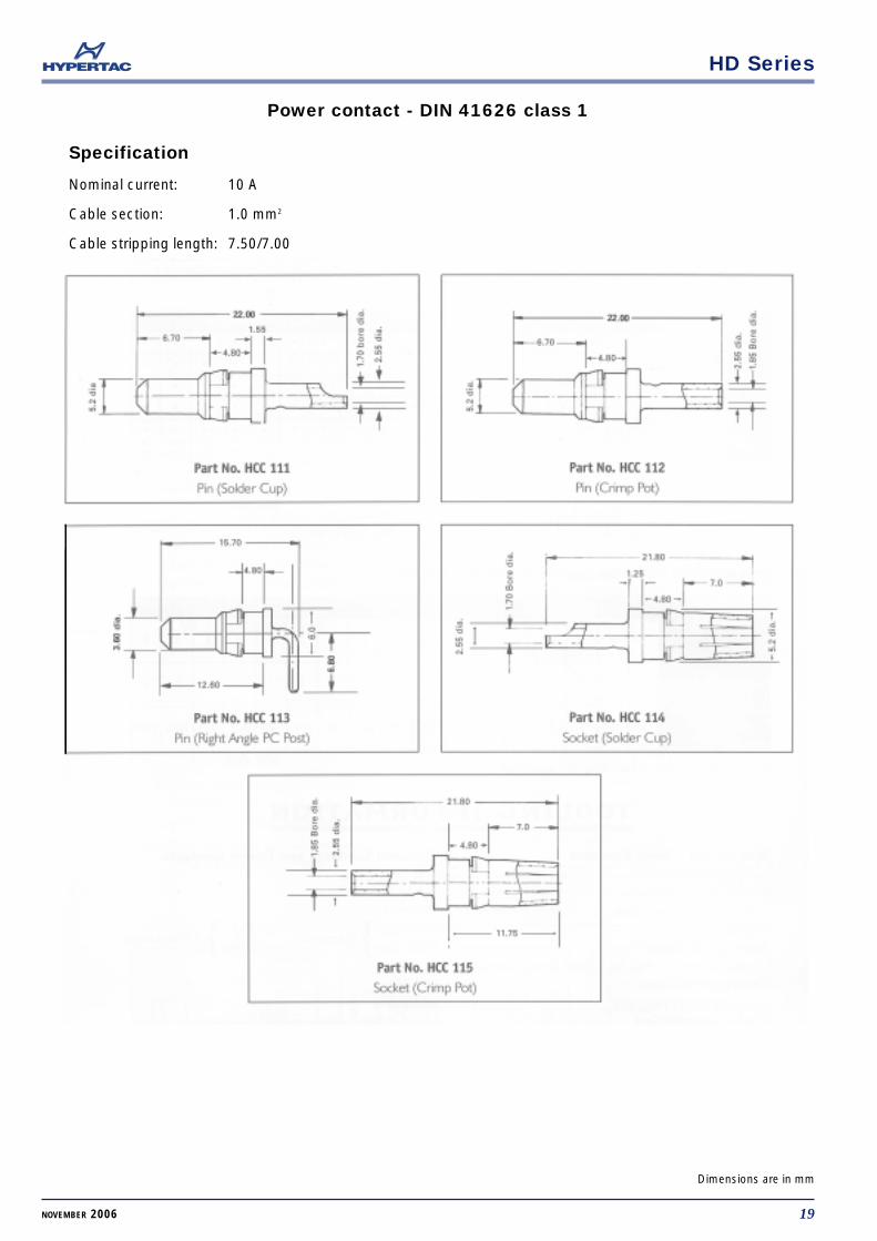
Power contact - DIN 41626 class 1
19NOVEMBER 2006
Dimensions are in mm
Specification
Nominal current: 10 A
Cable section: 1.0 mm2
Cable stripping length: 7.50/7.00
HD Series
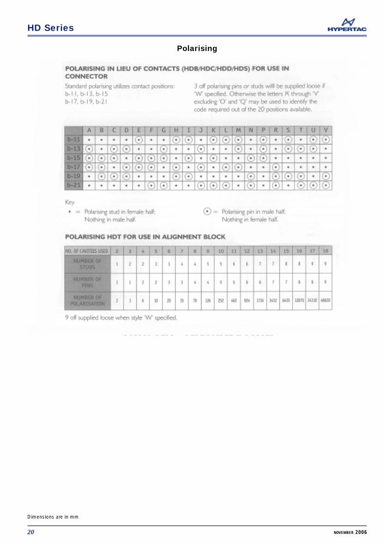
Polarising
20 NOVEMBER 2006
Dimensions are in mm
HD Series
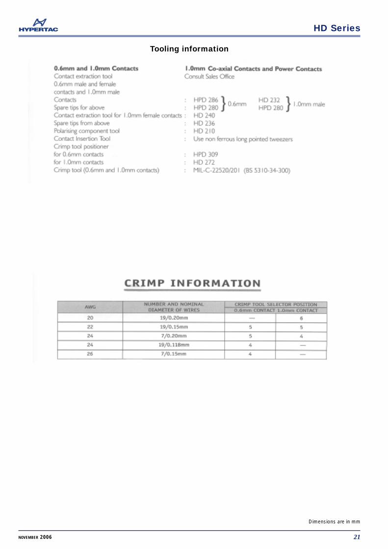
Tooling information
21NOVEMBER 2006
Dimensions are in mm
HD Series
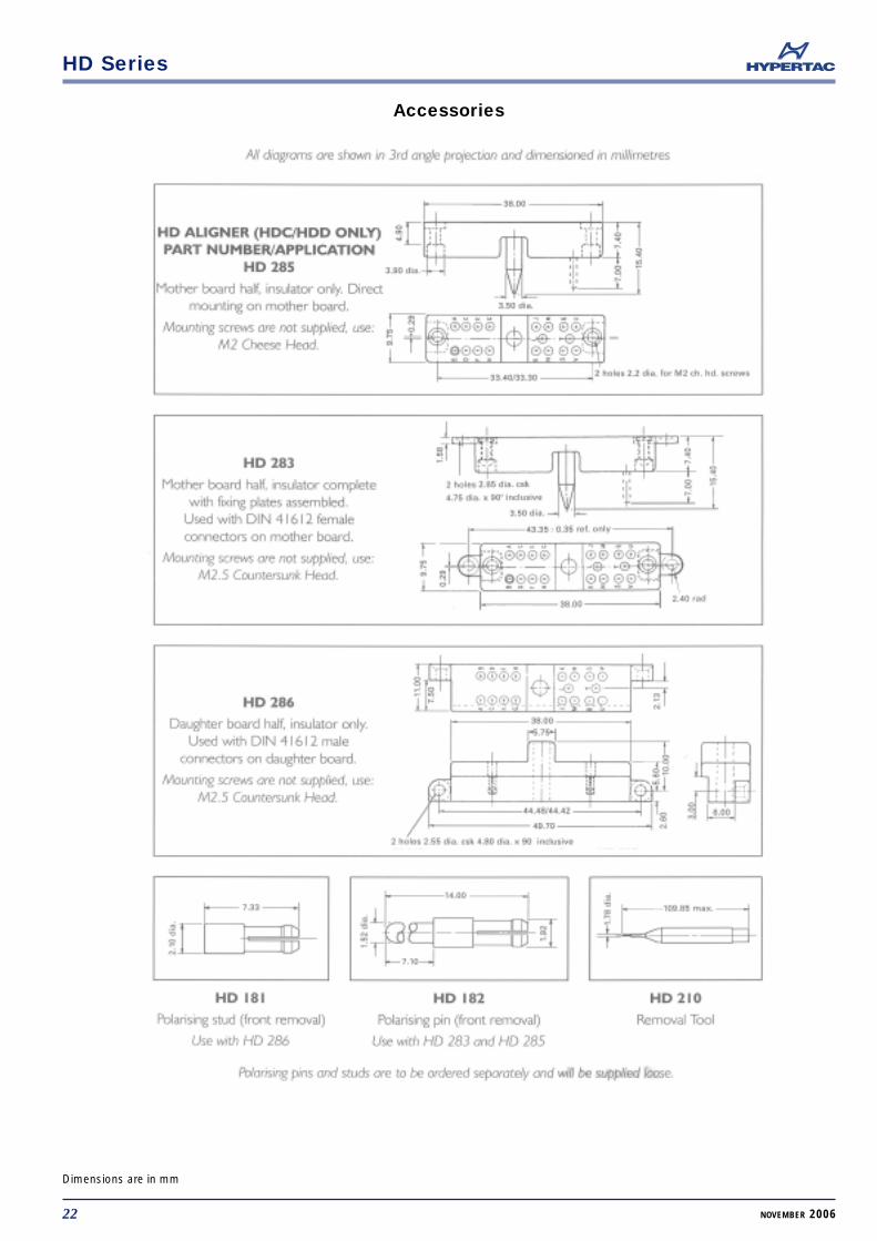
Accessories
22 NOVEMBER 2006
Dimensions are in mm
HD Series
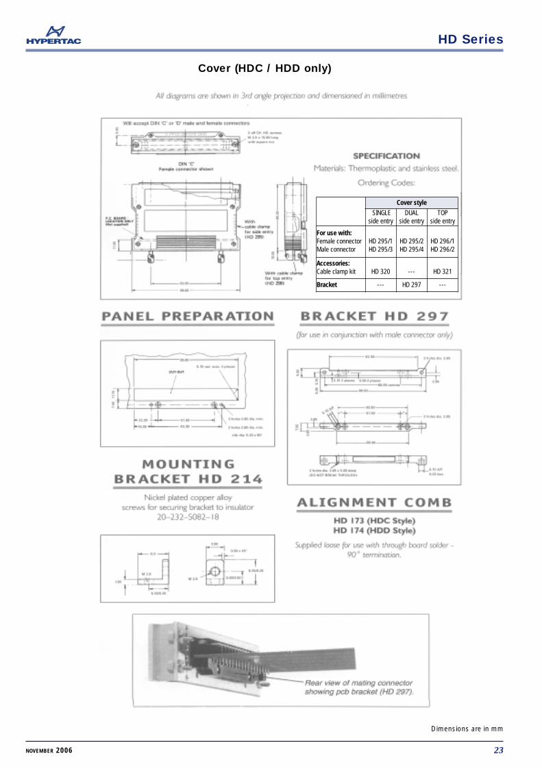
Cover (HDC / HDD only)
23NOVEMBER 2006
Dimensions are in mm
Cover style
SINGLEside entry
DUALside entry
TOPside entry
For use with:Female connectorMale connector
HD 295/1HD 295/3
HD 295/2HD 295/4
HD 296/1HD 296/2
Accessories:Cable clamp kit HD 320 --- HD 321
Bracket --- HD 297 ---