Embed Size (px)
Citation preview
HD-TVI
Dome Camera User Manual
User Manual Thank you for purchasing our product. If there are any questions, or requests, please do not hesitate to contact the dealer.
This manual may contain several technical incorrect places or printing errors, and the content is subject to change without notice. The updates will be added to the new version of this manual. We will readily improve or update the products or procedures described in the manual.
Privacy Notice
Surveillance laws vary by jurisdiction. Check all relevant laws in your jurisdiction before using all this product for surveillance purpose to ensure that your use of this product conforms.
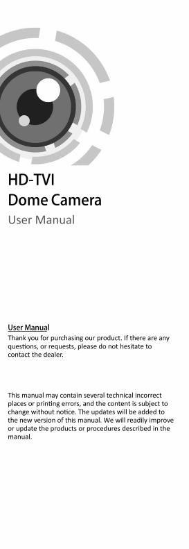
Regulatory Information FCC Information
FCC compliance: This equipment has been tested and found to comply with the limits for a digital device, pursuant to part 15 of the FCC Rules. These limits are designed to provide reasonable protection against harmful interference when the equipment is operated in a commercial environment. This equipment generates, uses, and can radiate radio frequency energy and, if not installed and used in accordance with the instruction manual, may cause harmful interference to radio communications. Operation of this equipment in a residential area is likely to cause harmful interference in which case the user will be required to correct the interference at his own expense.
FCC Conditions
This device complies with part 15 of the FCC Rules. Operation is subject to the following two conditions:
1. This device may not cause harmful interference.
2. This device must accept any interference received, including interference that may cause undesired operation
EU Conformity Statement
This product and - if applicable - the supplied accessories too are marked with "CE" and comply therefore with the applicable harmonized European
standards listed under the Low Voltage Directive 2006/95/EC, the EMC Directive 2004/108/EC.
2002/96/EC (WEEE directive): Products marked with this symbol cannot be disposed of as unsorted municipal waste in the European Union. For proper recycling, return this product to your local supplier
upon the purchase of equivalent new equipment, or dispose of it at designated collection points. For more information see: www.recyclethis.info.
2006/66/EC (battery directive): This product contains a battery that cannot be disposed of as unsorted municipal waste in the European Union. See the product documentation for specific battery information. The battery is marked with
this symbol, which may include lettering to indicate cadmium (Cd), lead (Pb), or mercury (Hg). For proper recycling, return the battery to your supplier or to a designated collection point. For more information see: www.recyclethis.info.
Industry Canada ICES-003 Compliance
This device meets the CAN ICES-3 (A)/NMB-3(A) standards requirements.
1 Introduction
1.1 Product Features This series of camera adopts high performance sensor and advanced circuit board design technology. It features high resolution, low distortion, and low noise, etc. It is suitable for surveillance system and image process system. The main features are as follows:
High performance CMOS sensor and high resolution bring high-quality image;
Low illumination, 0.01 Lux @ (F1.2, AGC ON), 0 Lux with IR;
IR cut filter with auto switch;
OSD menu, parameters are configurable;
Auto white balance and internal synchronization;
SMART IR mode;
True WDR;
Advanced 3-axis design meets different installation requirements;
1.2 Overview
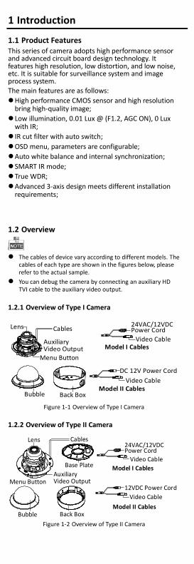
The cables of device vary according to different models. The cables of each type are shown in the figures below, please refer to the actual sample.
You can debug the camera by connecting an auxiliary HD TVI cable to the auxiliary video output.
1.2.1 Overview of Type I Camera
Bubble
Auxiliary Video Output
Lens
Back Box
Menu Button
Video Cable
24VAC/12VDC Power Cord Cables
Video Cable
DC 12V Power Cord
Model I Cables
Model II Cables
Figure 1-1 Overview of Type I Camera
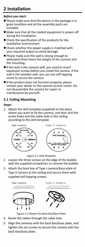
1.2.2 Overview of Type II Camera
Bubble
Auxiliary Video Output
Lens
Back Box
Menu Button
Video Cable
24VAC/12VDC Power Cord
Cables
Video Cable
12VDC Power Cord
Model I Cables
Model II Cables
Base Plate
Figure 1-2 Overview of Type II Camera
2 Installation
Before you start:
Please make sure that the device in the package is in good condition and all the assembly parts are included.
Make sure that all the related equipment is power-off during the installation.
Check the specification of the products for the installation environment.
Check whether the power supply is matched with your required output to avoid damage.
Please make sure the wall is strong enough to withstand three times the weight of the camera and the mounting.
If the wall is the cement wall, you need to insert expansion screws before you install the camera. If the wall is the wooden wall, you can use self-tapping screw to secure the camera.
If the product does not function properly, please contact your dealer or the nearest service center. Do not disassemble the camera for repair or maintenance by yourself.
2.1 Ceiling Mounting
Steps:
1. Attach the drill template (supplied) to the place where you want to fix the camera, and then drill the screw holes and the cable hole in the ceiling according to the drill template.
Type I Camera:
T y p e I I C a m e r a:
Figure 2-1 Drill Template
2. Loosen the three screws on the edge of the bubble with the supplied screwdriver to remove the bubble.
3. Attach the back box of Type I camera/base plate of Type II camera to the ceiling and secure them with
supplied self-tapping screws.
Type I Camera:
T y p e I I C a m e r a:
Figure 2-2 Attach the Back Box/Base Plate
4. Route the cables through the cable hole.
5. Align the cameras with the back box/base plate, and tighten the set screws to secure the camera with the
back box/base plate.
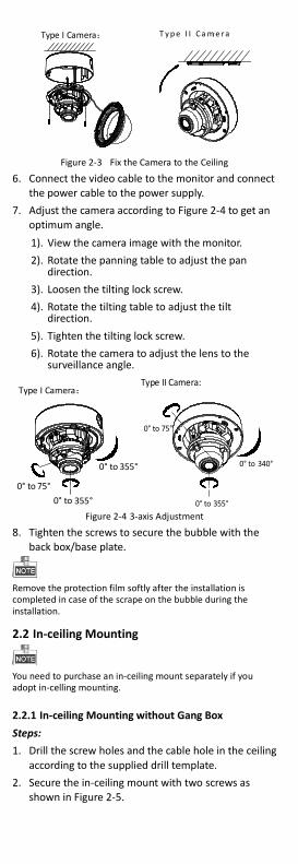
Type I Camera:
T y p e I I C a m e r a:
Figure 2-3 Fix the Camera to the Ceiling
6. Connect the video cable to the monitor and connect the power cable to the power supply.
7. Adjust the camera according to Figure 2-4 to get an optimum angle.
1). View the camera image with the monitor.
2). Rotate the panning table to adjust the pan direction.
3). Loosen the tilting lock screw.
4). Rotate the tilting table to adjust the tilt direction.
5). Tighten the tilting lock screw.
6). Rotate the camera to adjust the lens to the surveillance angle.
Type I Camera:
0° to 355°
0° to 355°
0° to 75°
0° to 355°
0° to 340°
0° to 75°
Type II Camera:
Figure 2-4 3-axis Adjustment
8. Tighten the screws to secure the bubble with the back box/base plate.
Remove the protection film softly after the installation is completed in case of the scrape on the bubble during the installation.
2.2 In-ceiling Mounting
You need to purchase an in-ceiling mount separately if you adopt in-celling mounting.
2.2.1 In-ceiling Mounting without Gang Box
Steps:
1. Drill the screw holes and the cable hole in the ceiling
according to the supplied drill template.
2. Secure the in-ceiling mount with two screws as shown in Figure 2-5.
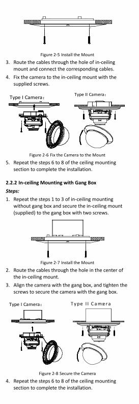
Figure 2-5 Install the Mount
3. Route the cables through the hole of in-ceiling mount and connect the corresponding cables.
4. Fix the camera to the in-ceiling mount with the supplied screws.
Type I Camera:
Type II Camera:
Figure 2-6 Fix the Camera to the Mount
5. Repeat the steps 6 to 8 of the ceiling mounting section to complete the installation.
2.2.2 In-ceiling Mounting with Gang Box
Steps:
1. Repeat the steps 1 to 3 of in-ceiling mounting without gang box and secure the in-ceiling mount (supplied) to the gang box with two screws.
Figure 2-7 Install the Mount
2. Route the cables through the hole in the center of the in-ceiling mount.
3. Align the camera with the gang box, and tighten the screws to secure the camera with the gang box.
Type I Camera:
T y pe I I C a m e r a:
Figure 2-8 Secure the Camera
4. Repeat the steps 6 to 8 of the ceiling mounting section to complete the installation.
2.3 Mounting with Inclined Base of Type I Camera
Steps:
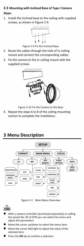
1. Install the inclined base to the ceiling with supplied
screws, as shown in Figure 2-9.
Figure 2-9 Fix the Inclined Base
2. Route the cables through the hole of in-ceiling mount and connect the corresponding cables.
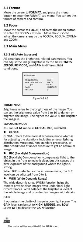
3. Fix the camera to the in-ceiling mount with the
supplied screws.
Figure 2-10 Fix the Camera to the Base
4. Repeat the steps 6 to 8 of the ceiling mounting section to complete the installation.
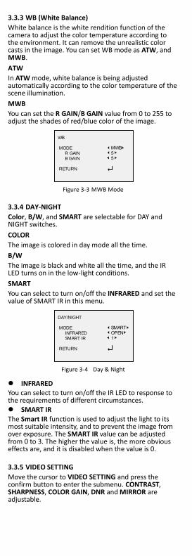
3 Menu Description
MAIN MENU
AE WBDAY
&NIGHTVIDEO
SETTINGRESET
SAVE&EXITBRIGHTNESS
EXPOSURE MODE
GAIN
ATW
MWB
COLOR
B/W
CONTRAST
SHARPNESS
COLORGAIN
DNR
MIRROR
SMART
FORMAT FOCUS
SETUP
Figure 3-1 Main Menu Overview
With a camera controller (purchased separately) or calling
the preset No. 95 of DVR you can select the menu and adjust the parameters.
Move the cursor up/down to select the menu item.
Move the cursor left/right to adjust the value of the selected item.
Press the OK key to confirm a selection.
3.1 Format Move the cursor to FORMAT, and press the menu button to enter the FORMAT sub menu. You can set the format of camera and confirm.
3.2 Focus Move the cursor to FOCUS, and press the menu button to enter the FOCUS sub menu. Move the cursor to adjust the camera lens by the FOCUS+, FOCUS-, ZOOM+ and ZOOM-.
3.3 Main Menu
3.3.2 AE (Auto Exposure)
AE describes the brightness-related parameters. You can adjust the image brightness by the BRIGHTNESS, EXPOSURE MODE, and GAIN in different light conditions.
EXPOSURE
BRIGHTNESS EXPOSURE MODE LV GAIN RETURN
5BLC5MIDDLE
Figure 3-2 AE
BRIGHTNESS
Brightness refers to the brightness of the image. You can set the brightness value from 1 to 10 to darken or brighten the image. The higher the value is, the brighter the image is.
EXPOSURE MODE
You can set AE mode as GLOBAL, BLC, and WDR. GLOBAL GLOBAL refers to the normal exposure mode which is for adjusting the situations including unusual lighting distribution, variations, non-standard processing, or other conditions of under exposure to get an optimum image. BLC (Backlight Compensation)
BLC (Backlight Compensation) compensate light to the object in the front to make it clear, but this causes the over-exposure of the background where the light is strong. When BLC is selected as the exposure mode, the BLC level can be adjusted from 0 to 8. WDR (Wide Dynamic Range) The wide dynamic range (WDR) function helps the camera provide clear images even under back light circumstances. WDR balances the brightness level of the whole image and provide clear images with details.
GAIN
It optimizes the clarity of image in poor light scene. The GAIN level can be set to HIGH, MIDDLE, and LOW. Select OFF to disable the GAIN function.
The noise will be amplified if the GAIN is on.
3.3.3 WB (White Balance)
White balance is the white rendition function of the camera to adjust the color temperature according to the environment. It can remove the unrealistic color casts in the image. You can set WB mode as ATW, and MWB.
ATW
In ATW mode, white balance is being adjusted automatically according to the color temperature of the scene illumination.
MWB
You can set the R GAIN/B GAIN value from 0 to 255 to adjust the shades of red/blue color of the image.
WB
MODE R GAIN B GAIN RETURN
MWB55
Figure 3-3 MWB Mode
3.3.4 DAY-NIGHT
Color, B/W, and SMART are selectable for DAY and NIGHT switches.
COLOR
The image is colored in day mode all the time.
B/W
The image is black and white all the time, and the IR LED turns on in the low-light conditions.
SMART
You can select to turn on/off the INFRARED and set the value of SMART IR in this menu.
DAY/NIGHT
MODE INFRARED SMART IR RETURN
SMARTOPEN1
Figure 3-4 Day & Night
INFRARED You can select to turn on/off the IR LED to response to the requirements of different circumstances. SMART IR
The Smart IR function is used to adjust the light to its most suitable intensity, and to prevent the image from over exposure. The SMART IR value can be adjusted from 0 to 3. The higher the value is, the more obvious effects are, and it is disabled when the value is 0.
3.3.5 VIDEO SETTING
Move the cursor to VIDEO SETTING and press the confirm button to enter the submenu. CONTRAST, SHARPNESS, COLOR GAIN, DNR and MIRROR are adjustable.
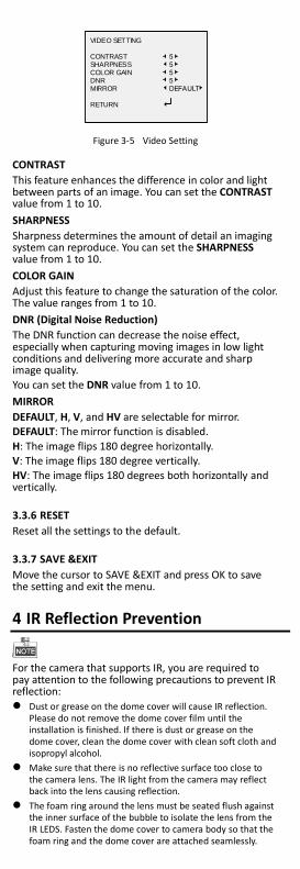
VIDEO SETTING
CONTRASTSHARPNESS COLOR GAIN DNRMIRROR RETURN
5555DEFAULT
Figure 3-5 Video Setting
CONTRAST
This feature enhances the difference in color and light between parts of an image. You can set the CONTRAST value from 1 to 10.
SHARPNESS
Sharpness determines the amount of detail an imaging system can reproduce. You can set the SHARPNESS value from 1 to 10.
COLOR GAIN
Adjust this feature to change the saturation of the color. The value ranges from 1 to 10.
DNR (Digital Noise Reduction)
The DNR function can decrease the noise effect, especially when capturing moving images in low light conditions and delivering more accurate and sharp image quality.
You can set the DNR value from 1 to 10.
MIRROR
DEFAULT, H, V, and HV are selectable for mirror. DEFAULT: The mirror function is disabled.
H: The image flips 180 degree horizontally. V: The image flips 180 degree vertically. HV: The image flips 180 degrees both horizontally and vertically.
3.3.6 RESET
Reset all the settings to the default.
3.3.7 SAVE &EXIT
Move the cursor to SAVE &EXIT and press OK to save the setting and exit the menu.
4 IR Reflection Prevention
For the camera that supports IR, you are required to pay attention to the following precautions to prevent IR reflection: Dust or grease on the dome cover will cause IR reflection.
Please do not remove the dome cover film until the installation is finished. If there is dust or grease on the dome cover, clean the dome cover with clean soft cloth and isopropyl alcohol.
Make sure that there is no reflective surface too close to the camera lens. The IR light from the camera may reflect back into the lens causing reflection.
The foam ring around the lens must be seated flush against the inner surface of the bubble to isolate the lens from the IR LEDS. Fasten the dome cover to camera body so that the foam ring and the dome cover are attached seamlessly.