Embed Size (px)
Citation preview
HD-TVI Speed Dome
Quick Start Guide
UD02198B
HD-TVI Speed Dome·Quick Start Guide
i
Quick Start Guide
COPYRIGHT © 2016 Hangzhou Hikvision Digital Technology Co., Ltd.
ALL RIGHTS RESERVED.
Any and all information, including, among others, wordings, pictures, graphs are the properties of
Hangzhou Hikvision Digital Technology Co., Ltd. or its subsidiaries (hereinafter referred to be
“Hikvision”). This user manual (hereinafter referred to be “the Manual”) cannot be reproduced,
changed, translated, or distributed, partially or wholly, by any means, without the prior written
permission of Hikvision. Unless otherwise stipulated, Hikvision does not make any warranties,
guarantees or representations, express or implied, regarding to the Manual.
About this Manual
This Manual is applicable to HD-TVI Speed Domes.
The Manual includes instructions for using and managing the product. Pictures, charts, images and
all other information hereinafter are for description and explanation only. The information
contained in the Manual is subject to change, without notice, due to firmware updates or other
reasons. Please find the latest version in the company website (http://overseas.hikvision.com/en/).
Please use this user manual under the guidance of professionals.
Trademarks Acknowledgement
and other Hikvision’s trademarks and logos are the properties of Hikvision in various
jurisdictions. Other trademarks and logos mentioned below are the properties of their respective
owners.
Legal Disclaimer
TO THE MAXIMUM EXTENT PERMITTED BY APPLICABLE LAW, THE PRODUCT DESCRIBED, WITH ITS
HARDWARE, SOFTWARE AND FIRMWARE, IS PROVIDED “AS IS”, WITH ALL FAULTS AND ERRORS,
AND HIKVISION MAKES NO WARRANTIES, EXPRESS OR IMPLIED, INCLUDING WITHOUT LIMITATION,
MERCHANTABILITY, SATISFACTORY QUALITY, FITNESS FOR A PARTICULAR PURPOSE, AND
NON-INFRINGEMENT OF THIRD PARTY. IN NO EVENT WILL HIKVISION, ITS DIRECTORS, OFFICERS,
EMPLOYEES, OR AGENTS BE LIABLE TO YOU FOR ANY SPECIAL, CONSEQUENTIAL, INCIDENTAL, OR
INDIRECT DAMAGES, INCLUDING, AMONG OTHERS, DAMAGES FOR LOSS OF BUSINESS PROFITS,
BUSINESS INTERRUPTION, OR LOSS OF DATA OR DOCUMENTATION, IN CONNECTION WITH THE
USE OF THIS PRODUCT, EVEN IF HIKVISION HAS BEEN ADVISED OF THE POSSIBILITY OF SUCH
DAMAGES.
REGARDING TO THE PRODUCT WITH INTERNET ACCESS, THE USE OF PRODUCT SHALL BE WHOLLY
AT YOUR OWN RISKS. HIKVISION SHALL NOT TAKE ANY RESPONSIBILITES FOR ABNORMAL
OPERATION, PRIVACY LEAKAGE OR OTHER DAMAGES RESULTING FROM CYBER ATTACK, HACKER
ATTACK, VIRUS INSPECTION, OR OTHER INTERNET SECURITY RISKS; HOWEVER, HIKVISION WILL
PROVIDE TIMELY TECHNICAL SUPPORT IF REQUIRED.
SURVEILLANCE LAWS VARY BY JURISDICTION. PLEASE CHECK ALL RELEVANT LAWS IN YOUR
JURISDICTION BEFORE USING THIS PRODUCT IN ORDER TO ENSURE THAT YOUR USE CONFORMS
THE APPLICABLE LAW. HIKVISION SHALL NOT BE LIABLE IN THE EVENT THAT THIS PRODUCT IS USED
WITH ILLEGITIMATE PURPOSES.
HD-TVI Speed Dome·Quick Start Guide
ii
IN THE EVENT OF ANY CONFLICTS BETWEEN THIS MANUAL AND THE APPLICABLE LAW, THE LATER
PREVAILS.
03261060707
HD-TVI Speed Dome·Quick Start Guide
iii
Regulatory Information FCC Information
FCC compliance: This equipment has been tested and found to comply with the limits for a digital
device, pursuant to part 15 of the FCC Rules. These limits are designed to provide reasonable protection against harmful interference when the equipment is operated in a commercial environment. This equipment generates, uses, and can radiate radio frequency energy and, if not
installed and used in accordance with the instruction manual, may cause harmful interference to radio communications. Operation of this equipment in a residential area is likely to cause harmful interference in which case the user will be required to correct the interference at his own expense.
FCC Conditions
This device complies with part 15 of the FCC Rules. Operation is subject to the following two
conditions:
1. This device may not cause harmful interference. 2. This device must accept any interference received, including interference that may cause undesired operation
EU Conformity Statement
This product and - if applicable - the supplied accessories too are marked with "CE" and comply therefore with the applicable harmonized European standards listed
under the Low Voltage Directive 2006/95/EC, the EMC Directive 2004/108/EC, the RoHS Directive 2011/65/EU.
2012/19/EU (WEEE directive): Products marked with this symbol cannot be disposed of as unsorted municipal waste in the European Union. For proper recycling, return
this product to your local supplier upon the purchase of equivalent new equipment, or dispose of it at designated collection points. For more information see:
www.recyclethis.info. 2006/66/EC (battery directive): This product contains a battery that cannot be
disposed of as unsorted municipal waste in the European Union. See the product documentation for specific battery information. The battery is marked with this symbol, which may include lettering to indicate cadmium (Cd), lead (Pb), or mercury
(Hg). For proper recycling, return the battery to your supplier or to a designated collection point. For more information see: www.recyclethis.info.
Industry Canada ICES-003 Compliance
This device meets the CAN ICES-3 (A)/NMB-3(A) standards requirements.
HD-TVI Speed Dome·Quick Start Guide
iv
Safety Instruction These instructions are intended to ensure that user can use the product correctly to avoid danger
or property loss.
The precaution measure is divided into “Warnings” and “Cautions”
Warnings: Serious injury or death may occur if any of the warnings are neglected. Cautions: Injury or equipment damage may occur if any of the cautions are neglected.
Warnings All the electronic operation should be strictly compliance with the electrical safety regulations,
fire prevention regulations and other related regulations in your local region.
Please use the power adapter, which is provided by normal company. The standard of the power adapter is 24VAC10% or 12VDC10% (depending on models). The power consumption cannot be less than the required value.
Do not connect several devices to one power adapter as adapter overload may cause over-heat
or fire hazard.
Please make sure that the power has been disconnected before you wire, install or dismantle the speed dome.
When the product is installed on wall or ceiling, the device shall be firmly fixed.
If smoke, odors or noise rise from the device, turn off the power at once and unplug the power cable, and then please contact the service center.
If the product does not work properly, please contact your dealer or the nearest service center.
Never attempt to disassemble the speed dome yourself. (We shall not assume any responsibility for problems caused by unauthorized repair or maintenance.)
Cautions Do not drop the dome or subject it to physical shock, and do not expose it to high
electromagnetism radiation. Avoid the equipment installation on vibrations surface or places
subject to shock (ignorance can cause equipment damage).
Do not place the dome in extremely hot, cold, dusty or damp locations, otherwise fire or electrical shock will occur. The operating temperature should be -30°C ~ 65°C(outdoor speed dome) and -10°C ~ 50°C (indoor speed dome).
The dome cover for indoor use shall be kept from rain and moisture.
Exposing the equipment to direct sun light, low ventilation or heat source such as heater or
radiator is forbidden (ignorance can cause fire danger).
Warnings Follow these safeguards to
prevent serious injury or death.
Cautions Follow these precautions to prevent
potential injury or material damage.
HD-TVI Speed Dome·Quick Start Guide
v
Do not aim the speed dome at the sun or extra bright places. A blooming or smear may occur
otherwise (which is not a malfunction however), and affecting the endurance of sensor at the same time.
Please use the provided glove when open up the dome cover, avoid direct contact with the dome cover, because the acidic sweat of the fingers may erode the surface coating of the dome cover.
Please use a soft and dry cloth when clean inside and outside surfaces of the dome cover, do not
use alkaline detergents.
Please keep all wrappers after unpack them for future use. In case of any failure occurred, you need to return the speed dome to the factory with the original wrapper.Transportation without the original wrapper may result in damage on the speed dome and lead to additional costs.
HD-TVI Speed Dome·Quick Start Guide
vi
Table of Contents
1 Installation ........................................................................................................ 1
1.1 Connecting the Cables .............................................................................................................. 1 1.2 DIP Switch Settings ................................................................................................................... 2
1.2.1 5-inch Speed Dome Settings .............................................................................................. 2 1.2.2 5-inch IR & Mini IR Speed Dome Settings .......................................................................... 4 1.2.3 7-inch IR Speed Dome Settings .......................................................................................... 7 1.2.4 Mini Speed Dome Settings ................................................................................................ 9
1.3 Wiring and Installation ........................................................................................................... 11 1.3.1 Wiring .............................................................................................................................. 11 1.3.2 Installing the Bracket ....................................................................................................... 12 1.3.3 Setting the DIP Switch ..................................................................................................... 13 1.3.4 Installing the Speed Dome ............................................................................................... 13
2 In-door Mounting Applications....................................................................... 14
2.1 5-inch Speed Dome In-ceiling Mounting Applications ............................................................ 14 2.2 5-inch Speed Dome Ceiling Mounting Applications ................................................................ 16
2.2.1 Removing the Mounting Bracket ..................................................................................... 16 2.2.2 Wiring .............................................................................................................................. 17 2.2.3 Ceiling Mounting ............................................................................................................. 18
2.3 Mini Speed Dome In-ceiling Mounting Applications ............................................................... 20 2.4 Mini Speed Dome Ceiling Mounting Applications .................................................................. 22
2.4.1 Wiring .............................................................................................................................. 22 2.4.2 Ceiling Mounting ............................................................................................................. 22
3 Application and Operations ............................................................................ 24
3.1 System Application ................................................................................................................. 24 3.2 Basic Operations ..................................................................................................................... 24
3.2.1 Configuring Patrol ............................................................................................................ 25 3.2.2 Configuring Park Actions ................................................................................................. 28
4 Troubleshooting .............................................................................................. 30
4.1 Device Exceptions ................................................................................................................... 30 4.2 PTZ Control Exceptions ........................................................................................................... 30 4.3 Other Questions ..................................................................................................................... 30
HD-TVI Speed Dome·Quick Start Guide
1
1 Installation Before you start:
Check the package contents and make sure that the device in the package is in good condition and all the assembly parts are included.
There are several ways to install the analog speed dome. The wall mounting is taken as an example
below.
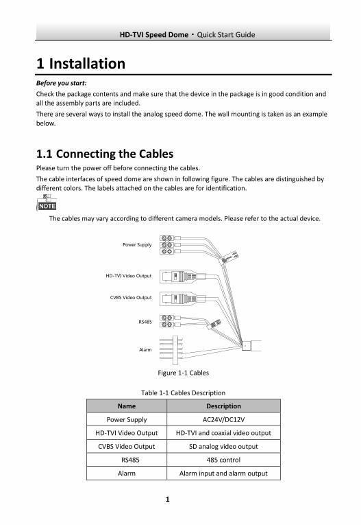
1.1 Connecting the Cables Please turn the power off before connecting the cables.
The cable interfaces of speed dome are shown in following figure. The cables are distinguished by different colors. The labels attached on the cables are for identification.
The cables may vary according to different camera models. Please refer to the actual device.
R E D
A C 2 4 V
Y E L L OW
/ GR E E N
B L A C K
A C 2 4 V
Y EL LO W
R 48 5-
O RA NG E
R 48 5+
VI
EO
D
Alarm
HD-TVI Video Output
Power Supply
VIEO
DCVBS Video Output
RS485
Figure 1-1 Cables
Table 1-1 Cables Description
Name Description Power Supply AC24V/DC12V
HD-TVI Video Output HD-TVI and coaxial video output CVBS Video Output SD analog video output
RS485 485 control Alarm Alarm input and alarm output
HD-TVI Speed Dome·Quick Start Guide
2
1.2 DIP Switch Settings
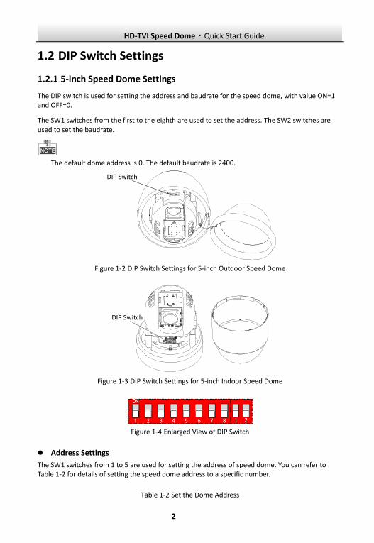
1.2.1 5-inch Speed Dome Settings
The DIP switch is used for setting the address and baudrate for the speed dome, with value ON=1 and OFF=0.
The SW1 switches from the first to the eighth are used to set the address. The SW2 switches are
used to set the baudrate.
The default dome address is 0. The default baudrate is 2400.
1 2 3 4 5 6 7 81
2
DIP Switch
Figure 1-2 DIP Switch Settings for 5-inch Outdoor Speed Dome
1 2 3 4 5 6 7 8
1 2
DIP Switch
Figure 1-3 DIP Switch Settings for 5-inch Indoor Speed Dome
Figure 1-4 Enlarged View of DIP Switch
Address Settings
The SW1 switches from 1 to 5 are used for setting the address of speed dome. You can refer to Table 1-2 for details of setting the speed dome address to a specific number.
Table 1-2 Set the Dome Address
HD-TVI Speed Dome·Quick Start Guide
3
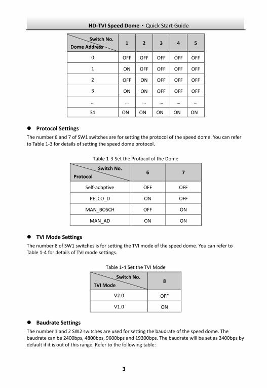
Switch No.
Dome Address 1 2 3 4 5
0 OFF OFF OFF OFF OFF
1 ON OFF OFF OFF OFF
2 OFF ON OFF OFF OFF
3 ON ON OFF OFF OFF
… … … … … …
31 ON ON ON ON ON
Protocol Settings
The number 6 and 7 of SW1 switches are for setting the protocol of the speed dome. You can refer to Table 1-3 for details of setting the speed dome protocol.
Table 1-3 Set the Protocol of the Dome
Switch No.
Protocol 6 7
Self-adaptive OFF OFF
PELCO_D ON OFF
MAN_BOSCH OFF ON
MAN_AD ON ON
TVI Mode Settings
The number 8 of SW1 switches is for setting the TVI mode of the speed dome. You can refer to Table 1-4 for details of TVI mode settings.
Table 1-4 Set the TVI Mode
Switch No.
TVI Mode 8
V2.0 OFF
V1.0 ON
Baudrate Settings
The number 1 and 2 SW2 switches are used for setting the baudrate of the speed dome. The baudrate can be 2400bps, 4800bps, 9600bps and 19200bps. The baudrate will be set as 2400bps by default if it is out of this range. Refer to the following table:
HD-TVI Speed Dome·Quick Start Guide
4
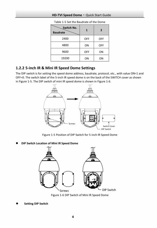
Table 1-5 Set the Baudrate of the Dome
Switch No.
Baudrate 1 2
2400 OFF OFF
4800 ON OFF
9600 OFF ON
19200 ON ON
1.2.2 5-inch IR & Mini IR Speed Dome Settings The DIP switch is for setting the speed dome address, baudrate, protocol, etc., with value ON=1 and
OFF=0. The switch label of the 5-inch IR speed dome is on the back of the SWITCH cover as shown in Figure 1-5. The DIP switch of mini IR speed dome is shown in Figure 1-6.
DIP Switch
ScrewsSwitch Cover
Figure 1-5 Position of DIP Switch for 5-inch IR Speed Dome
DIP Switch Location of Mini IR Speed Dome
Screws DIP Switch
Figure 1-6 DIP Switch of Mini IR Speed Dome
Setting DIP Switch
HD-TVI Speed Dome·Quick Start Guide
5
1 75 6432 8 9 10
ON DIP
1 2
ON
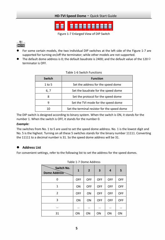
Figure 1-7 Enlarged View of DIP Switch
For some certain models, the two individual DIP switches at the left side of the Figure 1-7 are
supported for turning on/off the terminator; while other models are not supported.
The default dome address is 0; the default baudrate is 2400; and the default value of the 120Ω terminator is OFF.
Table 1-6 Switch Functions
Switch Function
1 to 5 Set the address for the speed dome
6, 7 Set the baudrate for the speed dome
8 Set the protocol for the speed dome
9 Set the TVI mode for the speed dome
10 Set the terminal resistor for the speed dome
The DIP switch is designed according to binary system. When the switch is ON, it stands for the number 1. When the switch is OFF, it stands for the number 0.
Example:
The switches from No. 1 to 5 are used to set the speed dome address. No. 1 is the lowest digit and No. 5 is the highest. Turning on all these 5 switches stands for the binary number 11111. Converting
the 11111 to a decimal number is 31. So the speed dome address will be 31.
Address List
For convenient settings, refer to the following list to set the address for the speed domes.
Table 1-7 Dome Address
Switch No.
Dome Address 1 2 3 4 5
0 OFF OFF OFF OFF OFF
1 ON OFF OFF OFF OFF
2 OFF ON OFF OFF OFF
3 ON ON OFF OFF OFF
… … … … … …
31 ON ON ON ON ON
HD-TVI Speed Dome·Quick Start Guide
6
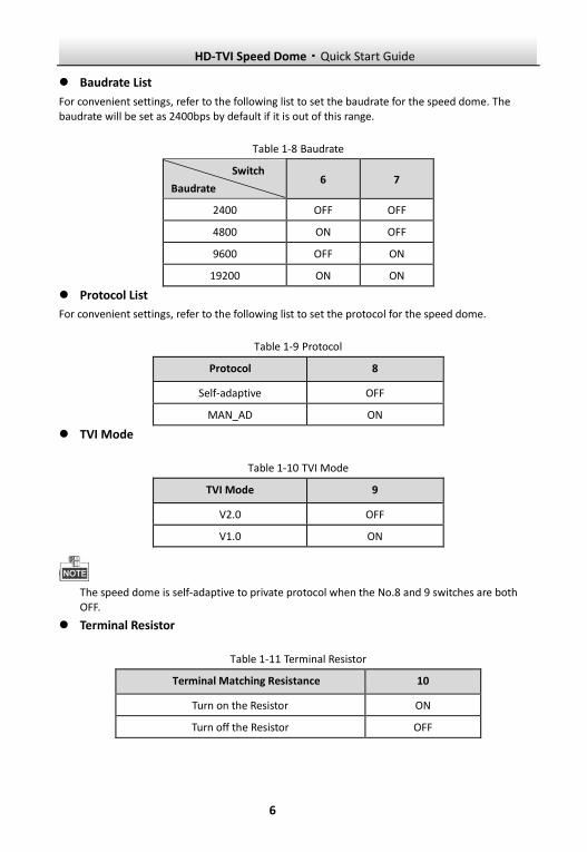
Baudrate List
For convenient settings, refer to the following list to set the baudrate for the speed dome. The baudrate will be set as 2400bps by default if it is out of this range.
Table 1-8 Baudrate
Switch Baudrate 6 7
2400 OFF OFF 4800 ON OFF 9600 OFF ON
19200 ON ON Protocol List
For convenient settings, refer to the following list to set the protocol for the speed dome.
Table 1-9 Protocol
Protocol 8
Self-adaptive OFF
MAN_AD ON
TVI Mode
Table 1-10 TVI Mode
TVI Mode 9
V2.0 OFF
V1.0 ON
The speed dome is self-adaptive to private protocol when the No.8 and 9 switches are both OFF.
Terminal Resistor
Table 1-11 Terminal Resistor
Terminal Matching Resistance 10
Turn on the Resistor ON
Turn off the Resistor OFF
HD-TVI Speed Dome·Quick Start Guide
7
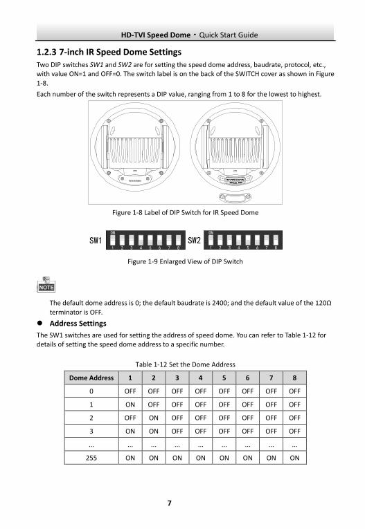
1.2.3 7-inch IR Speed Dome Settings Two DIP switches SW1 and SW2 are for setting the speed dome address, baudrate, protocol, etc., with value ON=1 and OFF=0. The switch label is on the back of the SWITCH cover as shown in Figure
1-8.
Each number of the switch represents a DIP value, ranging from 1 to 8 for the lowest to highest.
SW1 SW2
Figure 1-8 Label of DIP Switch for IR Speed Dome
ON
1 2 3 4 5 6 7 8
SW2ON
1 2 3 4 5 6 7 8
SW1
Figure 1-9 Enlarged View of DIP Switch
The default dome address is 0; the default baudrate is 2400; and the default value of the 120Ω
terminator is OFF.
Address Settings
The SW1 switches are used for setting the address of speed dome. You can refer to Table 1-12 for details of setting the speed dome address to a specific number.
Table 1-12 Set the Dome Address
Dome Address 1 2 3 4 5 6 7 8
0 OFF OFF OFF OFF OFF OFF OFF OFF
1 ON OFF OFF OFF OFF OFF OFF OFF
2 OFF ON OFF OFF OFF OFF OFF OFF
3 ON ON OFF OFF OFF OFF OFF OFF
... ... ... ... ... ... ... ... ...
255 ON ON ON ON ON ON ON ON
HD-TVI Speed Dome·Quick Start Guide
8
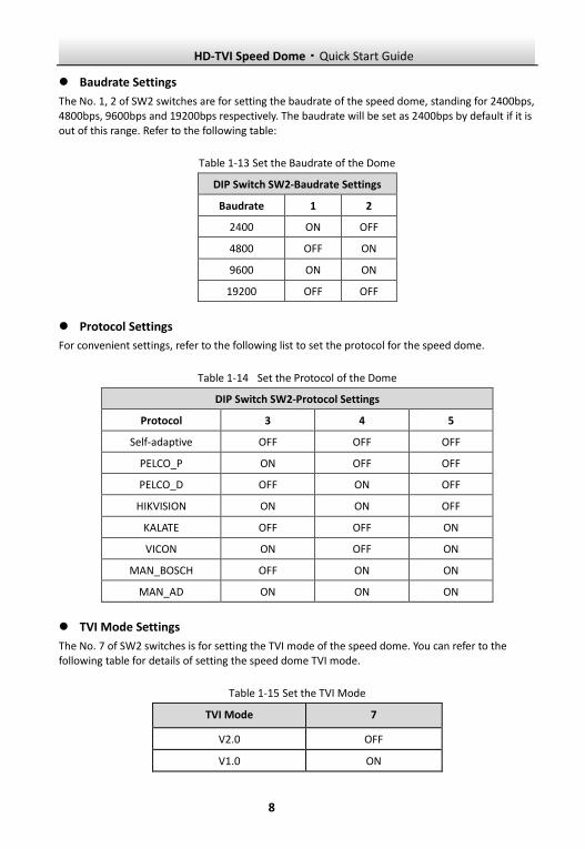
Baudrate Settings
The No. 1, 2 of SW2 switches are for setting the baudrate of the speed dome, standing for 2400bps, 4800bps, 9600bps and 19200bps respectively. The baudrate will be set as 2400bps by default if it is out of this range. Refer to the following table:
Table 1-13 Set the Baudrate of the Dome
DIP Switch SW2-Baudrate Settings
Baudrate 1 2
2400 ON OFF
4800 OFF ON
9600 ON ON
19200 OFF OFF
Protocol Settings
For convenient settings, refer to the following list to set the protocol for the speed dome.
Table 1-14 Set the Protocol of the Dome
DIP Switch SW2-Protocol Settings
Protocol 3 4 5
Self-adaptive OFF OFF OFF
PELCO_P ON OFF OFF
PELCO_D OFF ON OFF
HIKVISION ON ON OFF
KALATE OFF OFF ON
VICON ON OFF ON
MAN_BOSCH OFF ON ON
MAN_AD ON ON ON
TVI Mode Settings
The No. 7 of SW2 switches is for setting the TVI mode of the speed dome. You can refer to the following table for details of setting the speed dome TVI mode.
Table 1-15 Set the TVI Mode
TVI Mode 7
V2.0 OFF
V1.0 ON
HD-TVI Speed Dome·Quick Start Guide
9
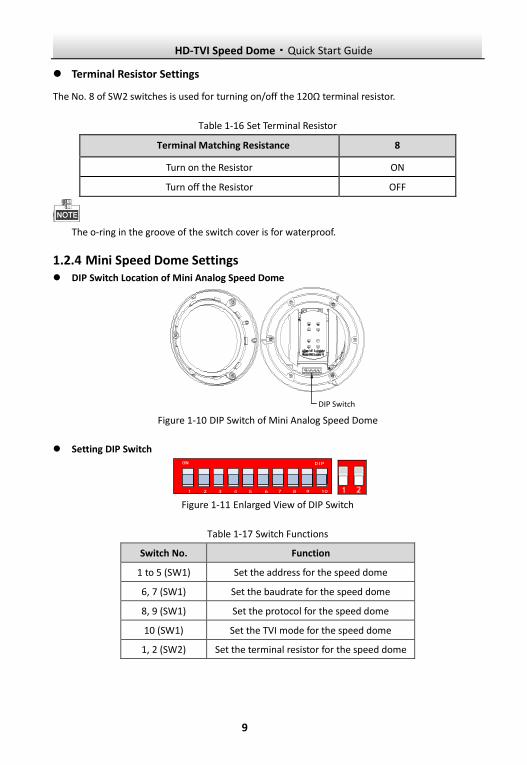
Terminal Resistor Settings
The No. 8 of SW2 switches is used for turning on/off the 120Ω terminal resistor.
Table 1-16 Set Terminal Resistor
Terminal Matching Resistance 8
Turn on the Resistor ON
Turn off the Resistor OFF
The o-ring in the groove of the switch cover is for waterproof.
1.2.4 Mini Speed Dome Settings DIP Switch Location of Mini Analog Speed Dome
DIP Switch
Figure 1-10 DIP Switch of Mini Analog Speed Dome
Setting DIP Switch
1 75 6432 8 9 10
ON DIP
1 2
ON
Figure 1-11 Enlarged View of DIP Switch
Table 1-17 Switch Functions
Switch No. Function
1 to 5 (SW1) Set the address for the speed dome
6, 7 (SW1) Set the baudrate for the speed dome
8, 9 (SW1) Set the protocol for the speed dome
10 (SW1) Set the TVI mode for the speed dome
1, 2 (SW2) Set the terminal resistor for the speed dome
HD-TVI Speed Dome·Quick Start Guide
10
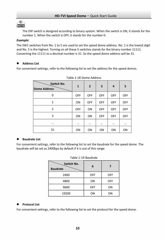
The DIP switch is designed according to binary system. When the switch is ON, it stands for the number 1. When the switch is OFF, it stands for the number 0.
Example:
The SW1 switches from No. 1 to 5 are used to set the speed dome address. No. 1 is the lowest digit and No. 5 is the highest. Turning on all these 5 switches stands for the binary number 11111.
Converting the 11111 to a decimal number is 31. So the speed dome address will be 31.
Address List
For convenient settings, refer to the following list to set the address for the speed domes.
Table 1-18 Dome Address
Switch No.
Dome Address 1 2 3 4 5
0 OFF OFF OFF OFF OFF
1 ON OFF OFF OFF OFF
2 OFF ON OFF OFF OFF
3 ON ON OFF OFF OFF
… … … … … …
31 ON ON ON ON ON
Baudrate List
For convenient settings, refer to the following list to set the baudrate for the speed dome. The baudrate will be set as 2400bps by default if it is out of this range.
Table 1-19 Baudrate
Switch No.
Baudrate 6 7
2400 OFF OFF
4800 ON OFF
9600 OFF ON
19200 ON ON
Protocol List
For convenient settings, refer to the following list to set the protocol for the speed dome.
HD-TVI Speed Dome·Quick Start Guide
11
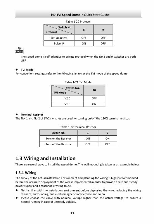
Table 1-20 Protocol
Switch No.
Protocol 8 9
Self-adaptive OFF OFF
Pelco_P ON OFF
The speed dome is self-adaptive to private protocol when the No.8 and 9 switches are both
OFF.
TVI Mode For convenient settings, refer to the following list to set the TVI mode of the speed dome.
Table 1-21 TVI Mode
Switch No.
TVI Mode 10
V2.0 OFF
V1.0 ON
Terminal Resistor The No. 1 and No.2 of SW2 switches are used for turning on/off the 120Ω terminal resistor.
Table 1-22 Terminal Resistor
Switch No. 1 2
Turn on the Resistor ON ON
Turn off the Resistor OFF OFF
1.3 Wiring and Installation There are several ways to install the speed dome. The wall mounting is taken as an example below.
1.3.1 Wiring The survey of the actual installation environment and planning the wiring is highly recommended
before the accurate deployment of the wire is implemented in order to provide a safe and steady power supply and a reasonable wiring route.
Get familiar with the installation environment before deploying the wire, including the wiring distance, surrounding, and electromagnetic interference and so on.
Please choose the cable with nominal voltage higher than the actual voltage, to ensure a normal running in case of unsteady voltage.
HD-TVI Speed Dome·Quick Start Guide
12
To protect the power cable and the signal transmitting cable from human tampering, you should pay attention to the protection and reinforcement of the cables.
When deploying the wire, please do not tighten the wire or make the wire loose.
The wiring of the speed dome should be performed by professionals.
1.3.2 Installing the Bracket Before you start:
Wall mounting is applicable to the indoor/outdoor solid wall construction. The followings are the
mandatory precondition for wall mounting:
The wall must be thick enough to install the expansion screws. Please make sure that the wall is strong enough to withstand more than 8 times the weight of
the dome and the mount.
Steps:
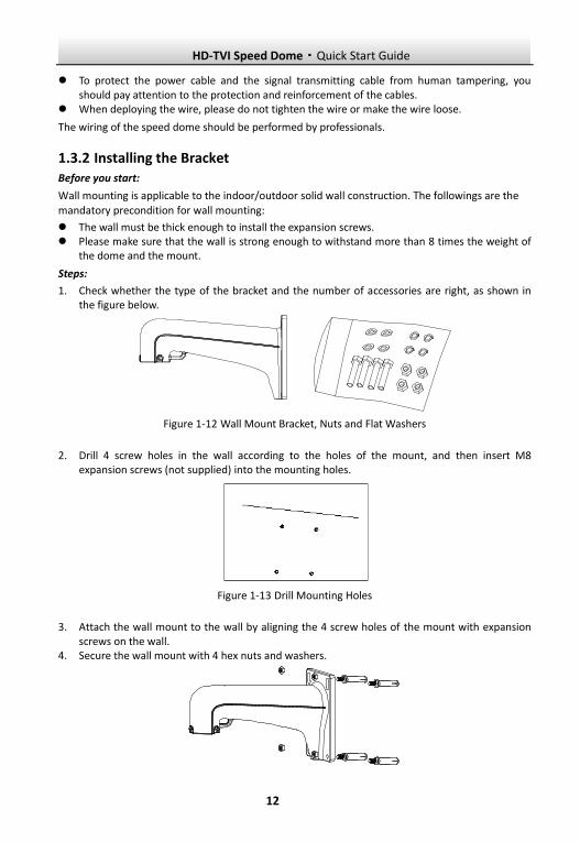
1. Check whether the type of the bracket and the number of accessories are right, as shown in the figure below.
Figure 1-12 Wall Mount Bracket, Nuts and Flat Washers
2. Drill 4 screw holes in the wall according to the holes of the mount, and then insert M8 expansion screws (not supplied) into the mounting holes.
Figure 1-13 Drill Mounting Holes
3. Attach the wall mount to the wall by aligning the 4 screw holes of the mount with expansion screws on the wall.
4. Secure the wall mount with 4 hex nuts and washers.
HD-TVI Speed Dome·Quick Start Guide
13
Figure 1-14 Secure the Mount
5. Install the speed dome to the mount. Please refer to Section 1.3.4 Installing the Speed Dome for installation details.
Follow the same instructions described above for the short-arm wall mounting. For outdoor applications, please adopt the water-proof measures. The short-arm wall mount is not recommended for outdoor applications.
1.3.3 Setting the DIP Switch Set the address and baudrate for the speed dome. The default value of DIP switch is shown below:
Address: 0 Baudrate:2400 Terminal Resistor: OFF
Please refer to the Section 1.2 DIP Switch Settings for DIP switch settings.
1.3.4 Installing the Speed Dome
The sketches of installing the speed dome are for reference only.
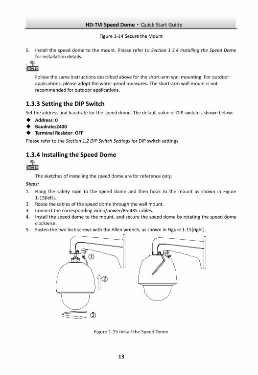
Steps:
1. Hang the safety rope to the speed dome and then hook to the mount as shown in Figure 1-15(left).
2. Route the cables of the speed dome through the wall mount. 3. Connect the corresponding video/power/RS-485 cables. 4. Install the speed dome to the mount, and secure the speed dome by rotating the speed dome
clockwise. 5. Fasten the two lock screws with the Allen wrench, as shown in Figure 1-15(right).
③
②
①
Figure 1-15 Install the Speed Dome
HD-TVI Speed Dome·Quick Start Guide
14
2 In-door Mounting Applications Before you start:
For cement wall, you need to use the expansion screw to fix the mount. The mounting hole of the expansion pipe on the wall should align with the mounting hole on the mount.
For wooden wall, you can just use the self-tapping screw to fix the mount.
2.1 5-inch Speed Dome In-ceiling Mounting Applications Before you start:
The in-ceiling mounting is applicable to the indoor ceiling construction. The followings are the mandatory precondition for mounting:
The height of the space above the ceiling must be more than 250mm. The thickness of the ceiling must ranges from 5 to 40mm. The ceiling must be strong enough to withstand more than 4 times the weight of the dome and
its accessories.
Steps:
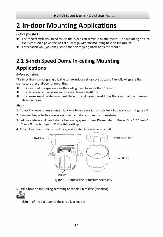
1. Rotate the lower dome counterclockwise to separate it from the back box as shown in Figure 2-1.
2. Remove the protective lens cover, foam and sticker from the dome drive.
3. Set the address and baudrate for the analog speed dome. Please refer to the Section 1.2.1 5-inch
Speed Dome Settings for DIP switch settings.
4. Attach lower dome to the back box, and rotate clockwise to secure it.
Protective Foam
Sticker
Lower Dome
Back Box
Figure 2-1 Remove the Protective Accessory
5. Drill a hole on the ceiling according to the drill template (supplied).
±2mm of the diameter of the circle is tolerable.
HD-TVI Speed Dome·Quick Start Guide
15
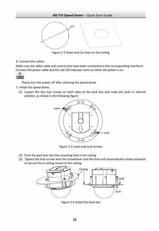
Figure 2-2 Draw and Cut Hole on the Ceiling
6. Connect the cables.
Make sure the video cable and control wire have been connected to the corresponding interfaces. Connect the power cable and the red LED indicator turns on when the power is on.
Please turn the power off after checking the speed dome.
7. Install the speed dome.
(1) Loosen the two lock screws on both sides of the back box and make the locks in internal position, as shown in the following figure:
Lock
Lock
Figure 2-3 Locks and Lock Screws
(2) Push the back box into the mounting hole in the ceiling (3) Tighten the lock screws with the screwdriver and the locks will automatically rotate outwards
to secure the in-ceiling mount to the ceiling.
Ceiling
Lock
Lock
Figure 2-4 Install the back box
HD-TVI Speed Dome·Quick Start Guide
16
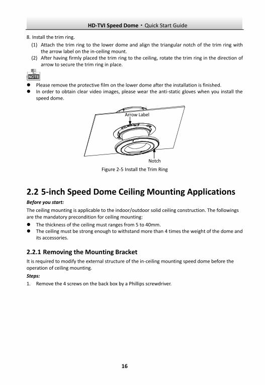
8. Install the trim ring.
(1) Attach the trim ring to the lower dome and align the triangular notch of the trim ring with the arrow label on the in-ceiling mount.
(2) After having firmly placed the trim ring to the ceiling, rotate the trim ring in the direction of arrow to secure the trim ring in place.
Please remove the protective film on the lower dome after the installation is finished. In order to obtain clear video images, please wear the anti-static gloves when you install the
speed dome.
Notch
Arrow Label
Figure 2-5 Install the Trim Ring
2.2 5-inch Speed Dome Ceiling Mounting Applications Before you start:
The ceiling mounting is applicable to the indoor/outdoor solid ceiling construction. The followings
are the mandatory precondition for ceiling mounting:
The thickness of the ceiling must ranges from 5 to 40mm. The ceiling must be strong enough to withstand more than 4 times the weight of the dome and
its accessories.
2.2.1 Removing the Mounting Bracket It is required to modify the external structure of the in-ceiling mounting speed dome before the operation of ceiling mounting.
Steps:
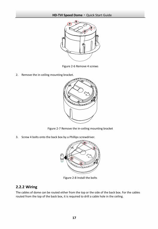
1. Remove the 4 screws on the back box by a Phillips screwdriver.
HD-TVI Speed Dome·Quick Start Guide
17
Figure 2-6 Remove 4 screws
2. Remove the in-ceiling mounting bracket.
Figure 2-7 Remove the in-ceiling mounting bracket
3. Screw 4 bolts onto the back box by a Phillips screwdriver.
Figure 2-8 Install the bolts
2.2.2 Wiring The cables of dome can be routed either from the top or the side of the back box. For the cables routed from the top of the back box, it is required to drill a cable hole in the ceiling.
HD-TVI Speed Dome·Quick Start Guide
18
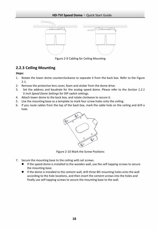
Figure 2-9 Cabling for Ceiling Mounting
2.2.3 Ceiling Mounting Steps:
1. Rotate the lower dome counterclockwise to separate it from the back box. Refer to the Figure 2-1.
2. Remove the protective lens cover, foam and sticker from the dome drive. 3. Set the address and baudrate for the analog speed dome. Please refer to the Section 1.2.1
5-inch Speed Dome Settings for DIP switch settings. 4. Attach lower dome to the back box, and rotate clockwise to secure it. 5. Use the mounting base as a template to mark four screw holes onto the ceiling. 6. If you route cables from the top of the back box, mark the cable hole on the ceiling and drill a
hole.
Figure 2-10 Mark the Screw Positions
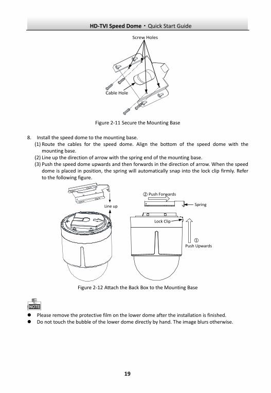
7. Secure the mounting base to the ceiling with set screws. If the speed dome is installed to the wooden wall, use the self-tapping screws to secure
the mounting base. If the dome is installed to the cement wall, drill three Φ5 mounting holes onto the wall
according to the hole locations, and then insert the cement screws into the holes and finally use self-tapping screws to secure the mounting base to the wall.
HD-TVI Speed Dome·Quick Start Guide
19
Screw Holes
Cable Hole
Figure 2-11 Secure the Mounting Base
8. Install the speed dome to the mounting base. (1) Route the cables for the speed dome. Align the bottom of the speed dome with the
mounting base. (2) Line up the direction of arrow with the spring end of the mounting base. (3) Push the speed dome upwards and then forwards in the direction of arrow. When the speed
dome is placed in position, the spring will automatically snap into the lock clip firmly. Refer to the following figure.
Line up
①
② Push Forwards
Push Upwards
Spring
Lock Clip
Figure 2-12 Attach the Back Box to the Mounting Base
Please remove the protective film on the lower dome after the installation is finished. Do not touch the bubble of the lower dome directly by hand. The image blurs otherwise.
HD-TVI Speed Dome·Quick Start Guide
20
2.3 Mini Speed Dome In-ceiling Mounting Applications Before you start:
The in-ceiling mounting is applicable to the indoor ceiling construction. The followings are the
mandatory precondition for mounting:
The height of the space above the ceiling must be more than 250mm. The ceiling must be with the thickness between 5 and 40mm. The ceiling must be strong enough to withstand more than 4 times the weight of the dome and
its accessories.
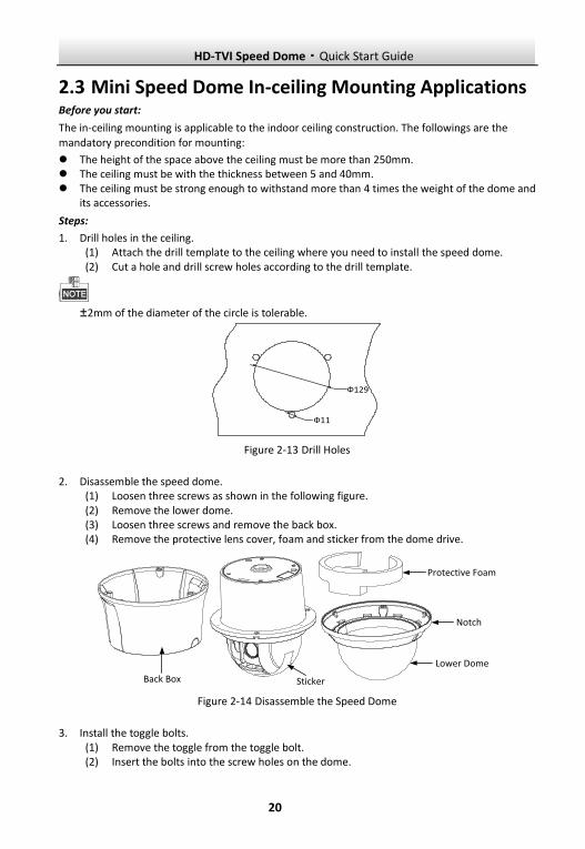
Steps:
1. Drill holes in the ceiling. (1) Attach the drill template to the ceiling where you need to install the speed dome. (2) Cut a hole and drill screw holes according to the drill template.
±2mm of the diameter of the circle is tolerable.
Ф129
Ф11
Figure 2-13 Drill Holes
2. Disassemble the speed dome. (1) Loosen three screws as shown in the following figure. (2) Remove the lower dome. (3) Loosen three screws and remove the back box. (4) Remove the protective lens cover, foam and sticker from the dome drive.
Protective Foam
Sticker
Notch
Lower Dome
Back Box
Figure 2-14 Disassemble the Speed Dome
3. Install the toggle bolts. (1) Remove the toggle from the toggle bolt. (2) Insert the bolts into the screw holes on the dome.
HD-TVI Speed Dome·Quick Start Guide
21
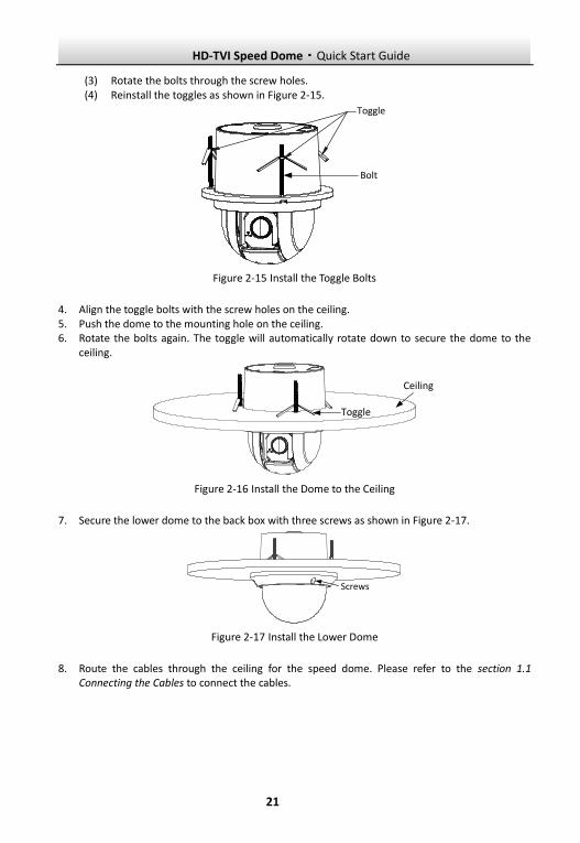
(3) Rotate the bolts through the screw holes. (4) Reinstall the toggles as shown in Figure 2-15.
Toggle
Bolt
Figure 2-15 Install the Toggle Bolts
4. Align the toggle bolts with the screw holes on the ceiling. 5. Push the dome to the mounting hole on the ceiling. 6. Rotate the bolts again. The toggle will automatically rotate down to secure the dome to the
ceiling.
Ceiling
Toggle
Figure 2-16 Install the Dome to the Ceiling
7. Secure the lower dome to the back box with three screws as shown in Figure 2-17.
Screws
Figure 2-17 Install the Lower Dome
8. Route the cables through the ceiling for the speed dome. Please refer to the section 1.1 Connecting the Cables to connect the cables.
HD-TVI Speed Dome·Quick Start Guide
22
2.4 Mini Speed Dome Ceiling Mounting Applications Before you start:
The ceiling mounting is applicable to the indoor/outdoor solid ceiling construction. The followings
are the mandatory precondition for ceiling mounting:
The ceiling must be with the thickness between 5 and 40mm. The ceiling must be strong enough to withstand more than 4 times the weight of the dome and
its accessories.
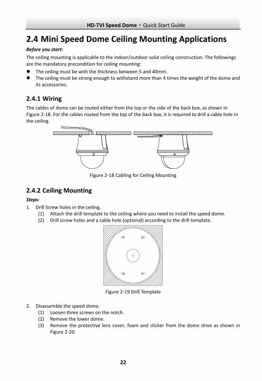
2.4.1 Wiring The cables of dome can be routed either from the top or the side of the back box, as shown in Figure 2-18. For the cables routed from the top of the back box, it is required to drill a cable hole in the ceiling.
Figure 2-18 Cabling for Ceiling Mounting
2.4.2 Ceiling Mounting Steps:
1. Drill Screw holes in the ceiling. (1) Attach the drill template to the ceiling where you need to install the speed dome. (2) Drill screw holes and a cable hole (optional) according to the drill template.
Figure 2-19 Drill Template
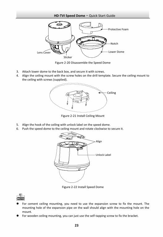
2. Disassemble the speed dome. (1) Loosen three screws on the notch. (2) Remove the lower dome. (3) Remove the protective lens cover, foam and sticker from the dome drive as shown in
Figure 2-20.
HD-TVI Speed Dome·Quick Start Guide
23
Sticker
Protective Foam
Notch
Lower DomeLens Cover
Figure 2-20 Disassemble the Speed Dome
3. Attach lower dome to the back box, and secure it with screws. 4. Align the ceiling mount with the screw holes on the drill template. Secure the ceiling mount to
the ceiling with screws (supplied).
Ceiling
Figure 2-21 Install Ceiling Mount
5. Align the hook of the ceiling with unlock label on the speed dome. 6. Push the speed dome to the ceiling mount and rotate clockwise to secure it.
Align
Unlock Label
Figure 2-22 Install Speed Dome
For cement ceiling mounting, you need to use the expansion screw to fix the mount. The
mounting hole of the expansion pipe on the wall should align with the mounting hole on the mount.
For wooden ceiling mounting, you can just use the self-tapping screw to fix the bracket.
HD-TVI Speed Dome·Quick Start Guide
24
3 Application and Operations
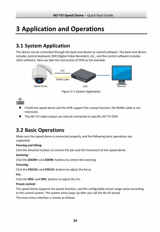
3.1 System Application The device can be controlled through the back-end device or control software. The back-end device
includes control keyboard, DVR (Digital Video Recorder), etc., and the control software includes client software. Here we take the connection of DVR as the example.
SYV
RS485 Cable
DVRSpeed Dome Monitor
Figure 3-1 System Application
If both the speed dome and the DVR support the coaxial function, the RS485 cable is not
necessary.
The HD-TVI video output can only be connected to specific HD-TVI DVR.
3.2 Basic Operations Make sure the speed dome is connected properly, and the following basic operations are
supported:
Panning and tilting:
Click the direction buttons to control the pan and tilt movement of the speed dome.
Zooming:
Click the ZOOM+ and ZOOM- buttons to control the zooming.
Focusing:
Click the FOCUS+ and FOCUS- buttons to adjust the focus.
Iris:
Click the IRIS+ and IRIS- buttons to adjust the iris.
Preset control:
The speed dome supports the preset function, and the configurable preset range varies according to the control system. The system menu pops up after you call the No.95 preset
The main menu interface is shown as follows:
HD-TVI Speed Dome·Quick Start Guide
25
MAIN MENUS
<SYSTEM INFO>
<DOME SETTINGS>
<RESTORE SETTINGS>
<RESTORE CAMERA>
<REBOOT DOME>
<LANGUAGE> ENGLISH
EXIT
Figure 3-2 Main Menu
Refer to the user manual for the detailed instruction to set the speed dome.
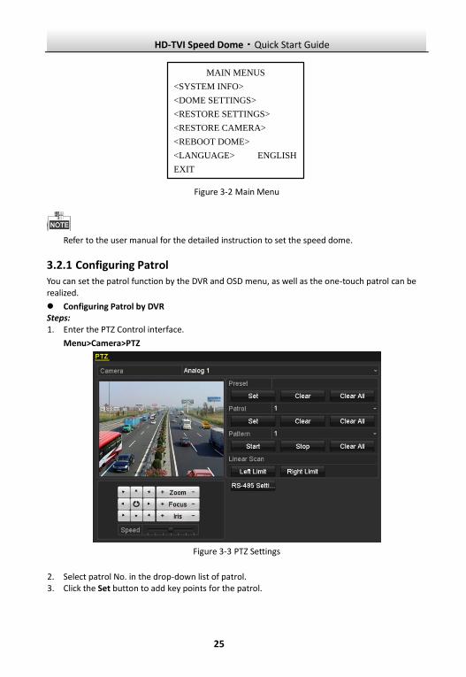
3.2.1 Configuring Patrol You can set the patrol function by the DVR and OSD menu, as well as the one-touch patrol can be realized.
Configuring Patrol by DVR Steps: 1. Enter the PTZ Control interface.
Menu>Camera>PTZ
Figure 3-3 PTZ Settings
2. Select patrol No. in the drop-down list of patrol. 3. Click the Set button to add key points for the patrol.
HD-TVI Speed Dome·Quick Start Guide
26
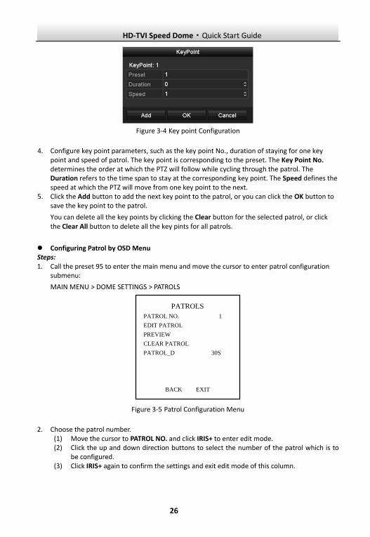
Figure 3-4 Key point Configuration
4. Configure key point parameters, such as the key point No., duration of staying for one key point and speed of patrol. The key point is corresponding to the preset. The Key Point No. determines the order at which the PTZ will follow while cycling through the patrol. The Duration refers to the time span to stay at the corresponding key point. The Speed defines the speed at which the PTZ will move from one key point to the next.
5. Click the Add button to add the next key point to the patrol, or you can click the OK button to save the key point to the patrol.
You can delete all the key points by clicking the Clear button for the selected patrol, or click the Clear All button to delete all the key pints for all patrols.
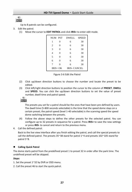
Configuring Patrol by OSD Menu Steps: 1. Call the preset 95 to enter the main menu and move the cursor to enter patrol configuration
submenu:
MAIN MENU > DOME SETTINGS > PATROLS
PATROLS
PATROL NO. 1
EDIT PATROL
PREVIEW
CLEAR PATROL
PATROL_D 30S
BACK EXIT
Figure 3-5 Patrol Configuration Menu
2. Choose the patrol number. (1) Move the cursor to PATROL NO. and click IRIS+ to enter edit mode. (2) Click the up and down direction buttons to select the number of the patrol which is to
be configured. (3) Click IRIS+ again to confirm the settings and exit edit mode of this column.
HD-TVI Speed Dome·Quick Start Guide
27
Up to 8 patrols can be configured.
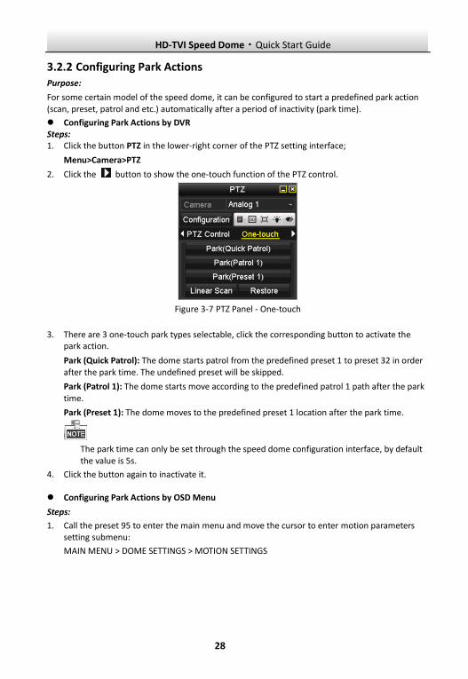
3. Edit the patrol. (1) Move the cursor to EDIT PATROL and click IRIS+ to enter edit mode.
NUM PST DWELL SPEED
1 0 6 30
2 0 6 30
3 0 6 30
4 0 6 30
5 0 6 30
6 0 6 30
7 0 6 30
IRIS+ OK IRIS- CANCEL
Figure 3-6 Edit the Patrol
(2) Click up/down direction buttons to choose the number and locate the preset to be edited.
(3) Click left/right direction buttons to position the cursor to the column of PRESET, DWELL and SPEED. You can click the up/down direction buttons to set the value of preset number, dwell time and patrol speed.
The presets you set for a patrol should be the ones that have been pre-defined by users. The dwell time (5-800 seconds selectable) is the time that the speed dome stays on a certain preset; the patrol speed (level 1-40 selectable) is the scanning speed the speed dome switching between the presets.
(4) Follow the above steps to define the other presets for the selected patrol. You can configure up to 32 presets in sequence for a patrol. Press IRIS+ to save the new settings or press IRIS- to cancel and return to the previous menu.
4. Call the defined patrol.
Back to the live view interface after you finish editing the patrol, and call the special presets to call the defined patrol. The presets 35~38 stand for patrol 1~4 and presets 102~105 stand for patrol 5~8.
Calling Quick Patrol
The dome starts patrol from the predefined preset 1 to preset 32 in order after the park time. The undefined preset will be skipped.
Steps:
1. Set the preset 1~32 by DVR or OSD menu.
2. Call the preset 46 to start the quick patrol.
HD-TVI Speed Dome·Quick Start Guide
28
3.2.2 Configuring Park Actions Purpose:
For some certain model of the speed dome, it can be configured to start a predefined park action (scan, preset, patrol and etc.) automatically after a period of inactivity (park time).
Configuring Park Actions by DVR Steps: 1. Click the button PTZ in the lower-right corner of the PTZ setting interface;
Menu>Camera>PTZ
2. Click the button to show the one-touch function of the PTZ control.
Figure 3-7 PTZ Panel - One-touch
3. There are 3 one-touch park types selectable, click the corresponding button to activate the park action.
Park (Quick Patrol): The dome starts patrol from the predefined preset 1 to preset 32 in order after the park time. The undefined preset will be skipped.
Park (Patrol 1): The dome starts move according to the predefined patrol 1 path after the park
time.
Park (Preset 1): The dome moves to the predefined preset 1 location after the park time.
The park time can only be set through the speed dome configuration interface, by default the value is 5s.
4. Click the button again to inactivate it. Configuring Park Actions by OSD Menu
Steps:
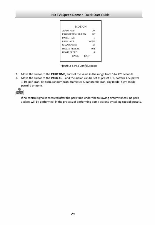
1. Call the preset 95 to enter the main menu and move the cursor to enter motion parameters setting submenu:
MAIN MENU > DOME SETTINGS > MOTION SETTINGS
HD-TVI Speed Dome·Quick Start Guide
29
MOTION
AUTO FLIP ON
PROPORTIONAL PAN ON
PARK TIME 5
PARK ACT NONE
SCAN SPEED 28
IMAGE FREEZE OFF
DOME SPEED 6
BACK EXIT
Figure 3-8 PTZ Configuration
2. Move the cursor to the PARK TIME, and set the value in the range from 5 to 720 seconds. 3. Move the cursor to the PARK ACT, and the action can be set as preset 1-8, pattern 1-5, patrol
1-10, pan scan, tilt scan, random scan, frame scan, panoramic scan, day mode, night mode, patrol-d or none.
If no control signal is received after the park time under the following circumstances, no park actions will be performed: in the process of performing dome actions by calling special presets.
HD-TVI Speed Dome·Quick Start Guide
30
4 Troubleshooting
4.1 Device Exceptions
Question
Why does the speed dome fail to start or repeatedly reboot? Why does the speed dome restart intermittently when controlling PTZ, calling presets or turning on the infrared lights of the IR dome at night?
Answer
Check the supply voltage of the dome. Ensure the supply voltage to meet the power
requirements of the speed dome. The nearest power supply is recommended.
Check whether the diameter of the power wire meet the standards.
4.2 PTZ Control Exceptions
Question
The speed dome cannot do PTZ control but can do zoom control.
Answer
For the 5 inch speed dome, you need to remove the protective sticker and foam of the camera
module by opening the bubble, correctly install the speed dome again and then wire up.
For IR speed dome, please remove the protective sticker and then wire up.
Question
Neither zoom control nor PTZ control is available for the speed dome.
Answer
Check the supply voltage of the dome. Ensure the supply voltage to meet the power requirements of the speed dome. The nearest power supply is recommended.
Check whether the diameter of the power wire meet the standards.
4.3 Other Questions
Question
The preview image of the speed dome is not clear.
HD-TVI Speed Dome·Quick Start Guide
31
Answer
Please check whether the protective film of the bubble has been removed.
Please check whether there are foreign objects on the bubble or the lens.
Please check where there are obstructions such as spider web nearby.
Open the bubble and check whether the lens cover has been removed.
Restore the device to the default settings. Call the preset 95 to enter the OSD menu and select the RESTORE CAMERA.
Question
For the IR speed dome, the image is abnormal white when the IR light is turned on in the night.
Answer
Please check whether there are obstructions near the lens, e.g. wall, leaf, spider web, cables, etc., which will cause the over-exposure due to the IR light reflection. Clear the obstructions if necessary.
Question
The speed dome cannot focus when working in the indoor condition.
Answer
Please restore the device to the default to exclude the factor of incorrect configuration.
Reduce the minimum focusing distance of the device by configuring the image settings through
the OSD menu.

HD-TVI Speed Dome·Quick Start Guide
32