Embed Size (px)
Citation preview
HD30 & HDP20 Series
69
Contents
HD30 & HDP20 Series Overview 70
Dimensions 70
Part Numbering System 71
Configurations 72-73
Wire Insulation 73
Special Modifications 73-74
Accessories 75-78
Mounting 78-79
How To Instructions 79-80
70
HD30 & HDP20 Series
HD30 & HDP20 Series Overview
Designed specifically for the truck, bus, and off-highway industry, the HD30 & HDP20 Series are heavy duty, environ-mentally sealed, multi-pin circular connectors. Available in metal or thermoplastic housings, these connectors offer multiple pin configurations that accept contact sizes 4 through 20.
The HD30 is a metal shell while the HDP20 Series shells are thermoplastic. Both feature quick connect-disconnect bayonet coupling, single hole bulkhead mounting, silicone seals, and a rear insertion/rear removal contact system.
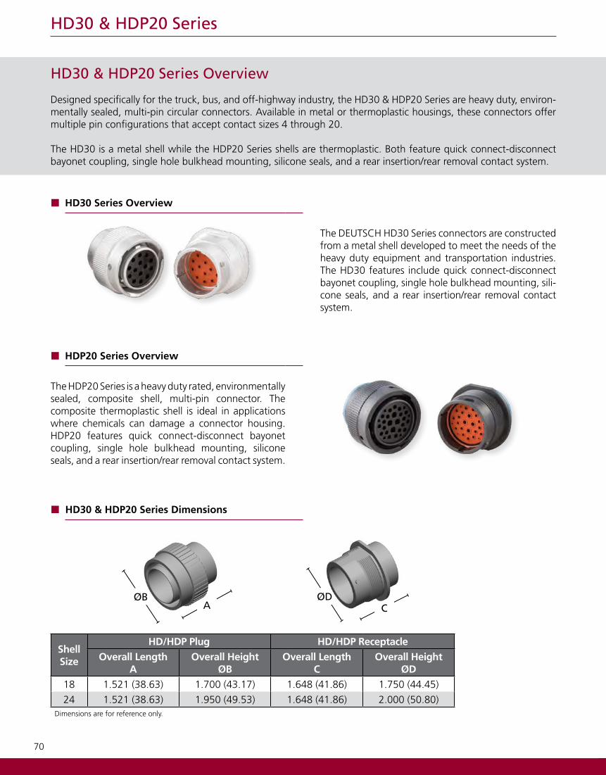
HD30 Series Overview
The DEUTSCH HD30 Series connectors are constructed from a metal shell developed to meet the needs of the heavy duty equipment and transportation industries. The HD30 features include quick connect-disconnect bayonet coupling, single hole bulkhead mounting, sili-cone seals, and a rear insertion/rear removal contact system.
HDP20 Series Overview
The HDP20 Series is a heavy duty rated, environmentally sealed, composite shell, multi-pin connector. The composite thermoplastic shell is ideal in applications where chemicals can damage a connector housing. HDP20 features quick connect-disconnect bayonet coupling, single hole bulkhead mounting, silicone seals, and a rear insertion/rear removal contact system.
ShellSize
HD/HDP Plug HD/HDP ReceptacleOverall Length
AOverall Height
ØB Overall Length
COverall Height
ØD18 1.521 (38.63) 1.700 (43.17) 1.648 (41.86) 1.750 (44.45)
24 1.521 (38.63) 1.950 (49.53) 1.648 (41.86) 2.000 (50.80)Dimensions are for reference only.
HD30 & HDP20 Series Dimensions
A CØDØB
71
HD30 & HDP20 Series
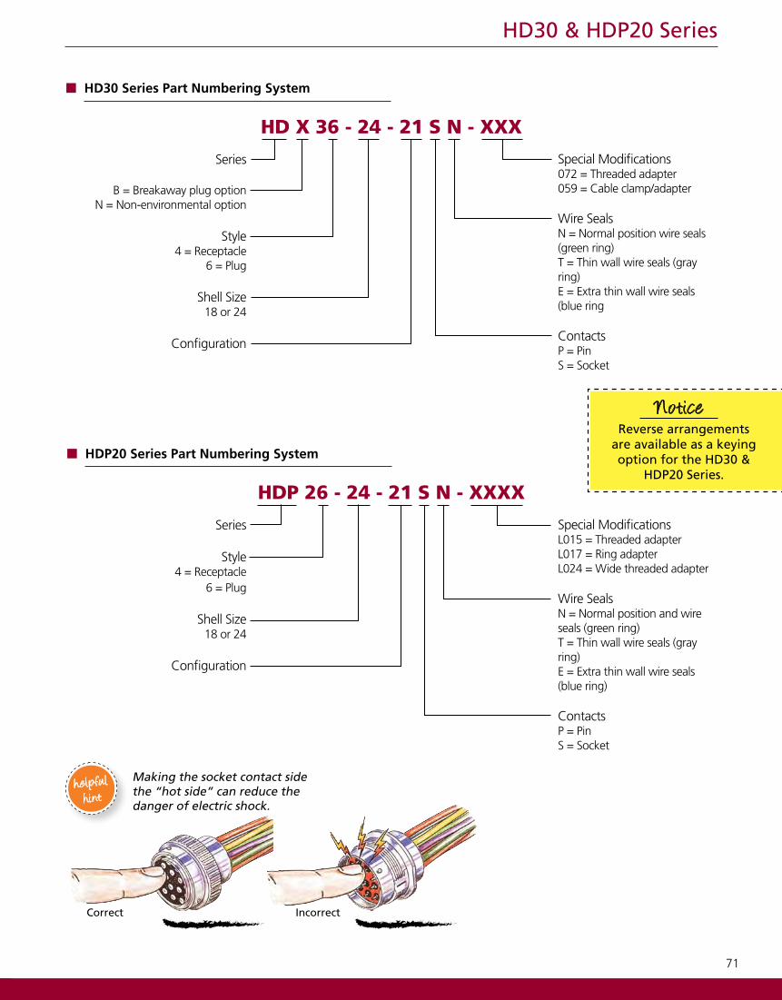
HD X 36 - 24 - 21 S N - XXX
Series
B = Breakaway plug optionN = Non-environmental option
Style4 = Receptacle
6 = Plug
Shell Size18 or 24
Configuration
Special Modifications 072 = Threaded adapter059 = Cable clamp/adapter
Wire SealsN = Normal position wire seals (green ring)T = Thin wall wire seals (gray ring)E = Extra thin wall wire seals (blue ring
ContactsP = Pin S = Socket
HDP 26 - 24 - 21 S N - XXXX
Series
Style4 = Receptacle
6 = Plug
Shell Size18 or 24
Configuration
Special Modifications L015 = Threaded adapterL017 = Ring adapterL024 = Wide threaded adapter
Wire SealsN = Normal position and wire seals (green ring)T = Thin wall wire seals (gray ring)E = Extra thin wall wire seals (blue ring)
ContactsP = Pin S = Socket
HD30 Series Part Numbering System
HDP20 Series Part Numbering System
Making the socket contact side the “hot side” can reduce the danger of electric shock.
helpfulhint
IncorrectCorrect
Reverse arrangements are available as a keying option for the HD30 &
HDP20 Series.
Notice
72
HD30 & HDP20 Series
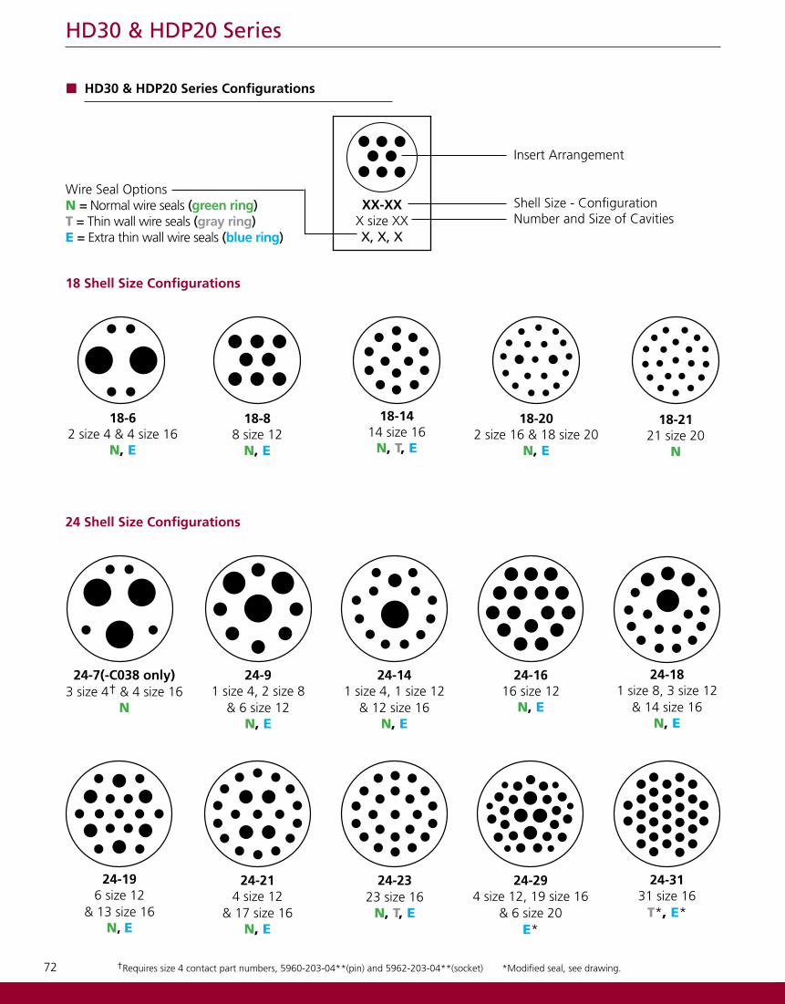
*Modified seal, see drawing.†Requires size 4 contact part numbers, 5960-203-04**(pin) and 5962-203-04**(socket)
18-88 size 12
N, E
18-1414 size 16
N, T, E
18-202 size 16 & 18 size 20
N, E
18-62 size 4 & 4 size 16
N, E
18-2121 size 20
N
24-7(-C038 only)3 size 4† & 4 size 16
N
1
24-141 size 4, 1 size 12
& 12 size 16N, E
24-1616 size 12
N, E
24-91 size 4, 2 size 8
& 6 size 12N, E
24-181 size 8, 3 size 12
& 14 size 16N, E
24-214 size 12
& 17 size 16N, E
3
24-196 size 12
& 13 size 16N, E
24-2323 size 16
N, T, E
XX-XXX size XXX, X, X
Wire Seal OptionsN = Normal wire seals (green ring)T = Thin wall wire seals (gray ring)E = Extra thin wall wire seals (blue ring)
Insert Arrangement
Shell Size - ConfigurationNumber and Size of Cavities
24-294 size 12, 19 size 16
& 6 size 20E*
24-3131 size 16
T*, E*
HD30 & HDP20 Series Configurations
24 Shell Size Configurations
18 Shell Size Configurations
73
HD30 & HDP20 Series
*Modified seal, see drawing ‡Without P064 modification, plug cavities 4 and 5 are internally connected
24-91-P064‡
2 size 8, 2 size 12 & 5 size 16
N, E
24-475 size16 & 42 size 20
E*
24-353 size 16 & 32 size 20
N, E
24-3333 size 20
N
ContactSize
Recommended Wire Insulation O.D.N Seal
Green RingT Seal
Gray RingE Seal
Blue Ring20 .040-.095 (1.02-2.41) .040-.095 (1.02-2.41) .040-.095 (1.02-2.41)16 .100-.134 (2.54-3.40) .088-.134 (2.23-3.40) .053-.120 (1.35-3.05)12 .134-.170 (3.40-4.32) .113-.170 (2.87-4.32) .097-.158 (2.46-4.01)
8 .190-.240 (4.83-6.10) .170-.240 (4.32-6.10) .135-.220 (3.43-5.59)
4 .280-.292 (7.11-7.42) .261-.292 (6.63-7.42) .261-.292 (6.63-7.42)
Wire Insulation
Color Coded Ring
Color code is visible from the rear of the receptacle or plug.
Green: Normal SealGray: Thin Wall SealBlue: Extra Thin Seal
Undersized wire insulation is a major cause for leakage.
Notice
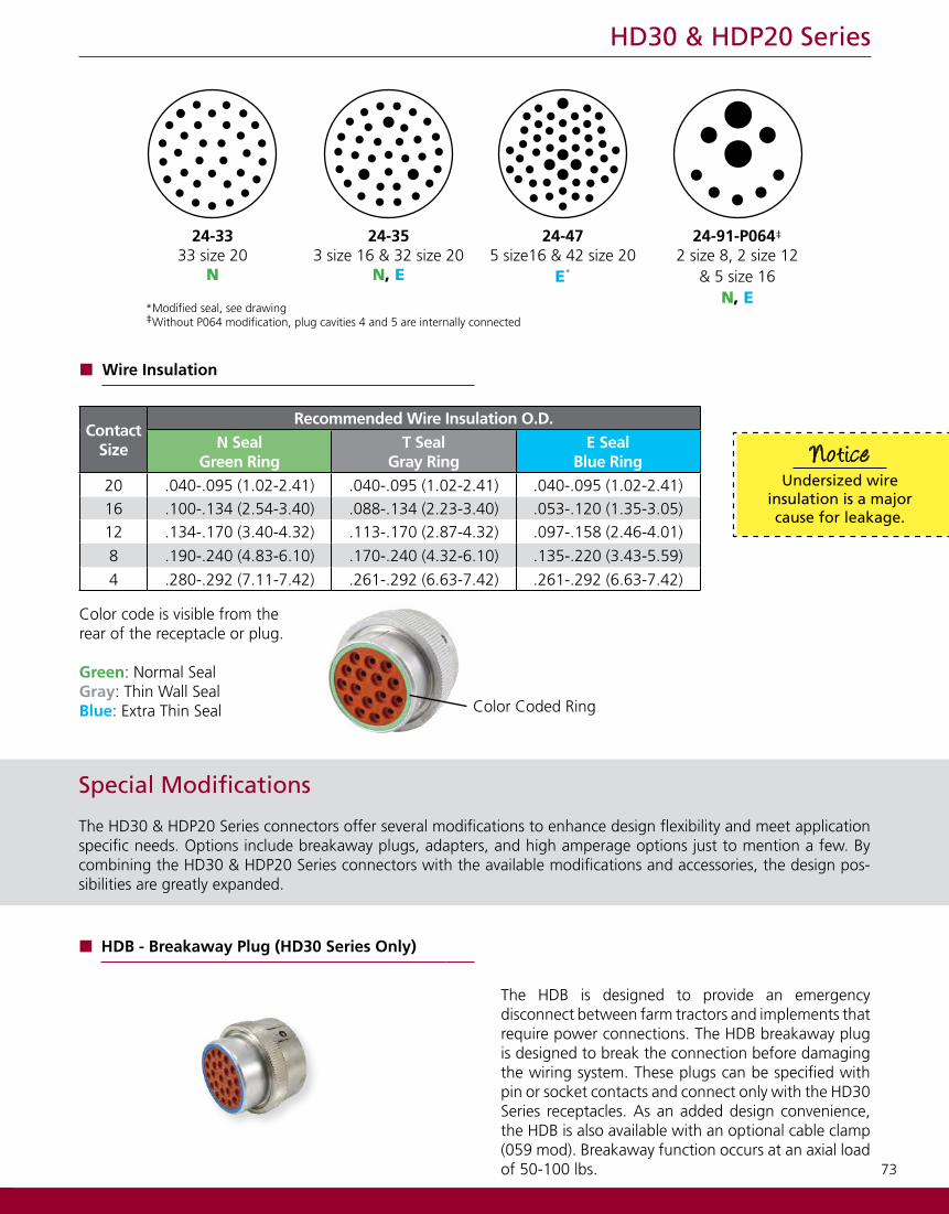
HDB - Breakaway Plug (HD30 Series Only)
The HDB is designed to provide an emergency disconnect between farm tractors and implements that require power connections. The HDB breakaway plug is designed to break the connection before damaging the wiring system. These plugs can be specified with pin or socket contacts and connect only with the HD30 Series receptacles. As an added design convenience, the HDB is also available with an optional cable clamp (059 mod). Breakaway function occurs at an axial load of 50-100 lbs.
Special Modifications
The HD30 & HDP20 Series connectors offer several modifications to enhance design flexibility and meet application specific needs. Options include breakaway plugs, adapters, and high amperage options just to mention a few. By combining the HD30 & HDP20 Series connectors with the available modifications and accessories, the design pos-sibilities are greatly expanded.
74
HD30 & HDP20 Series
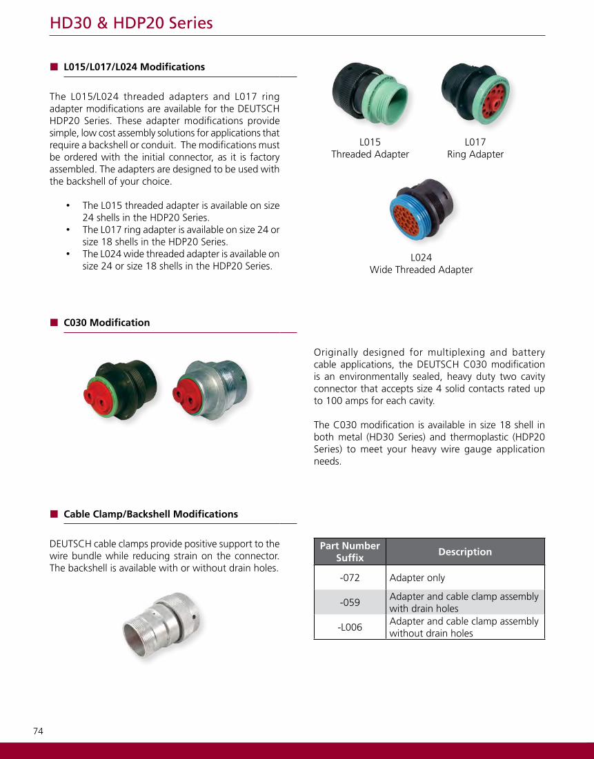
Cable Clamp/Backshell Modifications
DEUTSCH cable clamps provide positive support to the wire bundle while reducing strain on the connector. The backshell is available with or without drain holes.
Part NumberSuffix
Description
-072 Adapter only
-059Adapter and cable clamp assembly with drain holes
-L006Adapter and cable clamp assembly without drain holes
L015/L017/L024 Modifications
The L015/L024 threaded adapters and L017 ring adapter modifications are available for the DEUTSCH HDP20 Series. These adapter modifications provide simple, low cost assembly solutions for applications that require a backshell or conduit. The modifications must be ordered with the initial connector, as it is factory assembled. The adapters are designed to be used with the backshell of your choice.
• The L015 threaded adapter is available on size 24 shells in the HDP20 Series.
• The L017 ring adapter is available on size 24 or size 18 shells in the HDP20 Series.
• The L024 wide threaded adapter is available on size 24 or size 18 shells in the HDP20 Series.
L015Threaded Adapter
L017Ring Adapter
C030 Modification
Originally designed for multiplexing and battery cable applications, the DEUTSCH C030 modification is an environmentally sealed, heavy duty two cavity connector that accepts size 4 solid contacts rated up to 100 amps for each cavity.
The C030 modification is available in size 18 shell in both metal (HD30 Series) and thermoplastic (HDP20 Series) to meet your heavy wire gauge application needs.
L024Wide Threaded Adapter
75
HD30 & HDP20 Series
Accessories
Several accessory items can be used to complement the connectors. The HD30 & HDP20 family accessories include items such as boots, backshells, gaskets, and protective caps. Accessories are designed to complete the application and meet a wide array of design requirements such as solutions for mounting, providing additional protection, and offering increased aesthetics.
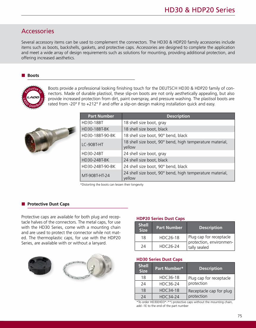
Boots
Boots provide a professional looking finishing touch for the DEUTSCH HD30 & HDP20 family of con-nectors. Made of durable plastisol, these slip-on boots are not only aesthetically appealing, but also provide increased protection from dirt, paint overspray, and pressure washing. The plastisol boots are rated from -20° F to +212° F and offer a slip-on design making installation quick and easy.
Part Number DescriptionHD30-18BT 18 shell size boot, gray
HD30-18BT-BK 18 shell size boot, black
HD30-18BT-90-BK 18 shell size boot, 90° bend, black
LC-90BT-HT18 shell size boot, 90° bend, high temperature material, yellow
HD30-24BT 24 shell size boot, gray
HD30-24BT-BK 24 shell size boot, black
HD30-24BT-90-BK 24 shell size boot, 90° bend, black
MT-90BT-HT-2424 shell size boot, 90° bend, high temperature material, yellow
*Distorting the boots can lessen their longevity
LA
D
D Distributio
n
Exclusive to
HDP20 Series Dust CapsShell Size
Part Number Description
18 HDC26-18 Plug cap for receptacle protection, environmen-tally sealed24 HDC26-24
HD30 Series Dust CapsShell Size
Part Number* Description
18 HDC36-18 Plug cap for receptacle protection24 HDC36-24
18 HDC34-18 Receptacle cap for plug protection24 HDC34-24
*To order HD30(HD3*-**) protective caps without the mounting chain, add -1E to the end of the part number
Protective Dust Caps
Protective caps are available for both plug and recep-tacle halves of the connectors. The metal caps, for use with the HD30 Series, come with a mounting chain and are used to protect the connector while not mat-ed. The thermoplastic caps, for use with the HDP20 Series, are available with or without a lanyard.
76
HD30 & HDP20 Series
HDP20 Series L015 Conduit AdapterShellSize
L015 Conduit AdapterPart Numbers
ConduitSize
24Seal Ring:
SRN21 Cap Nut:
CN2122 (mm) NW
SealRing
CapNut
HDP20 Series L015 BackshellShell Size
Cable Diameter Backshell Compression Nut
24.430-.570 M902-2243 M902-2053
.570-.710 M902-2244 M902-2054Backshell Technical Specifications:Material - PC/PET Polyester Blend, UV-Stabilized, Flame Retardant, BlackFlammability - UL94-VO, Weatherability - UL746C
Backshell CompressionNut
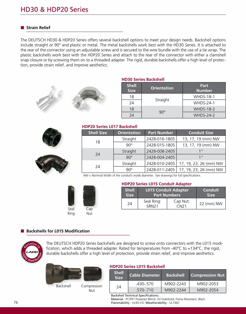
HD30 Series BackshellShell Size
OrientationPart
Number18
StraightWHDS-18-1
24 WHDS-24-1
1890°
WHDS-18-2
24 WHDS-24-2
Strain Relief
The DEUTSCH HD30 & HDP20 Series offers several backshell options to meet your design needs. Backshell options include straight or 90° and plastic or metal. The metal backshells work best with the HD30 Series. It is attached to the rear of the connector using an adjustable screw and is secured to the wire bundle with the use of a tie wrap. The plastic backshells work best with the HDP20 Series and attach to the rear of the connector with either a clamshell snap closure or by screwing them on to a threaded adapter. The rigid, durable backshells offer a high level of protec-tion, provide strain relief, and improve aesthetics.
HDP20 Series L017 BackshellShell Size Orientation Part Number Conduit Size
18Straight 2428-016-1805 13, 17, 19 (mm) NW
90º 2428-015-1805 13, 17, 19 (mm) NW
24Straight 2428-008-2405 1”
90º 2428-004-2405 1”
24Straight 2428-010-2405 17, 19, 23, 26 (mm) NW
90º 2428-011-2405 17, 19, 23, 26 (mm) NWNW = Nominal Width of the conduit’s inside diameter. See drawings for full specifications.
Backshells for L015 Modification
The DEUTSCH HDP20 Series backshells are designed to screw onto connectors with the L015 modi-fication, which adds a threaded adapter. Rated for temperatures from -40°C to +134°C, the rigid, durable backshells offer a high level of protection, provide strain relief, and improve aesthetics. L
AD
D Distributio
n
Exclusive to
77
HD30 & HDP20 Series
Backshells for L024 Modification
The DEUTSCH HDP20 Series backshells are designed to screw onto connectors with the L024 modification, which adds a wide threaded adapter. The rigid, durable backshells offer a high level of protection, provide strain relief, and improve aesthetics.
HDP20 Series L024 Backshell
Shell Size
Orientation Part Number
18 Straight 2428-025-1805
24 Straight 2428-024-2405
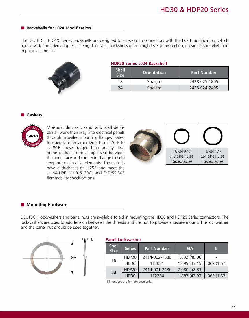
Gaskets
Moisture, dirt, salt, sand, and road debris can all work their way into electrical panels through unsealed mounting flanges. Rated to operate in environments from -70°F to +225°F, these rugged high quality neo-prene gaskets form a tight seal between the panel face and connector flange to help keep out destructive elements. The gaskets have a thickness of .125” and meet the UL-94-HBF, Mil-R-6130C, and FMVSS-302 flammability specifications.
16-04978 (18 Shell SizeReceptacle)
16-04477(24 Shell SizeReceptacle)
LA
D
D Distributio
n
Exclusive to
Panel LockwasherShellSize
Series Part Number ØA B
18HDP20 2414-002-1886 1.892 (48.06) -
HD30 114021 1.699 (43.15) .062 (1.57)
24HDP20 2414-001-2486 2.080 (52.83) -
HD30 112264 1.887 (47.93) .062 (1.57)Dimensions are for reference only.
B
ØA
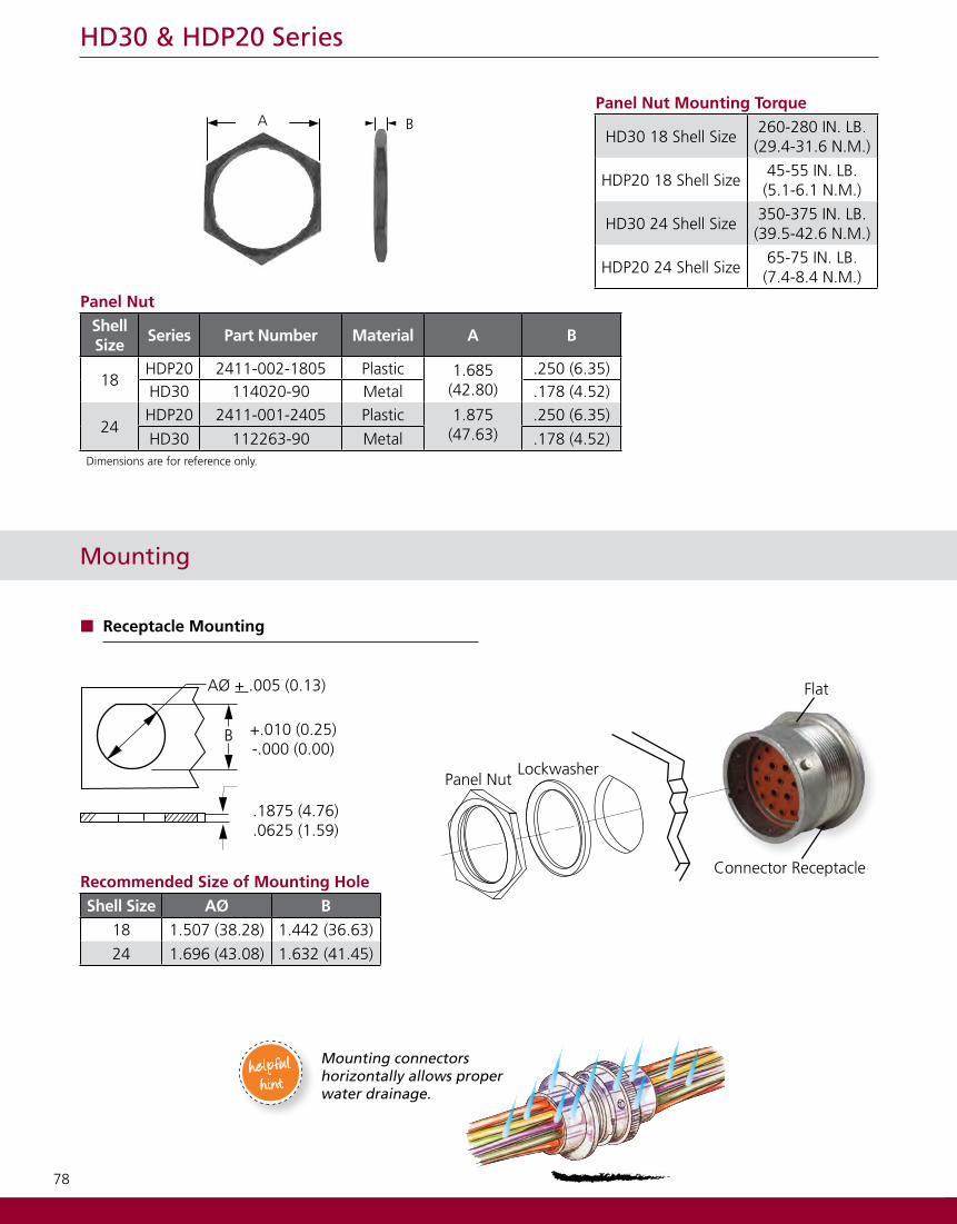
Mounting Hardware
DEUTSCH lockwashers and panel nuts are available to aid in mounting the HD30 and HDP20 Series connectors. The lockwashers are used to add tension between the threads and the nut to provide a secure mount. The lockwasher and the panel nut should be used together.
78
HD30 & HDP20 Series
Recommended Size of Mounting HoleShell Size AØ B
18 1.507 (38.28) 1.442 (36.63)
24 1.696 (43.08) 1.632 (41.45)
Mounting
Receptacle Mounting
AØ + .005 (0.13)
+.010 (0.25)-.000 (0.00)
.1875 (4.76)
.0625 (1.59)
B
Panel NutLockwasher
Connector Receptacle
Flat
Panel NutShellSize
Series Part Number Material A B
18HDP20 2411-002-1805 Plastic 1.685
(42.80).250 (6.35)
HD30 114020-90 Metal .178 (4.52)
24HDP20 2411-001-2405 Plastic 1.875
(47.63).250 (6.35)
HD30 112263-90 Metal .178 (4.52)Dimensions are for reference only.
Panel Nut Mounting Torque
HD30 18 Shell Size260-280 IN. LB.(29.4-31.6 N.M.)
HDP20 18 Shell Size45-55 IN. LB.(5.1-6.1 N.M.)
HD30 24 Shell Size350-375 IN. LB.(39.5-42.6 N.M.)
HDP20 24 Shell Size65-75 IN. LB.(7.4-8.4 N.M.)
A B
Mounting connectors horizontally allows proper water drainage.
helpfulhint
79
HD30 & HDP20 Series
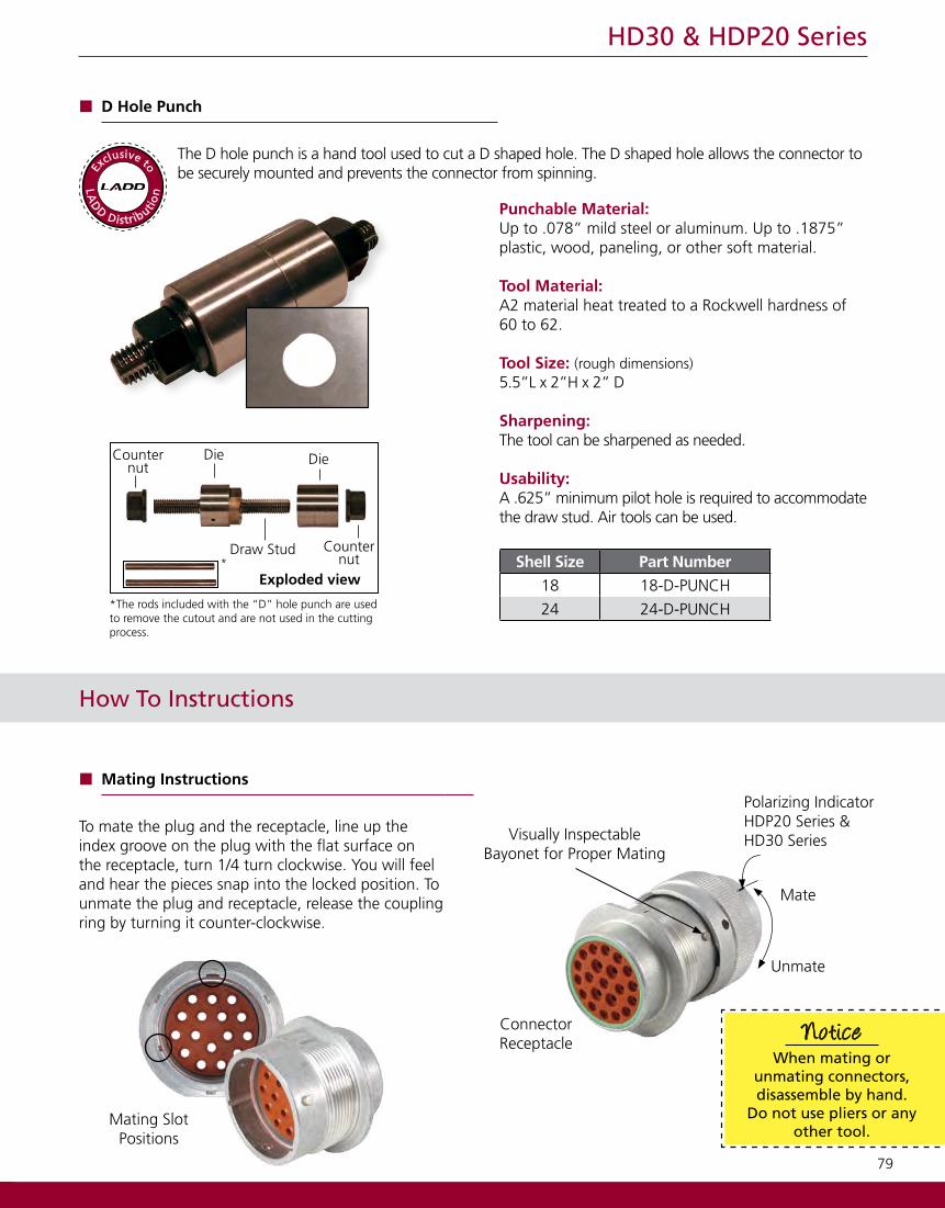
Punchable Material:Up to .078” mild steel or aluminum. Up to .1875” plastic, wood, paneling, or other soft material.
Tool Material:A2 material heat treated to a Rockwell hardness of 60 to 62.
Tool Size: (rough dimensions)5.5”L x 2”H x 2” D
Sharpening:The tool can be sharpened as needed.
Usability:A .625” minimum pilot hole is required to accommodate the draw stud. Air tools can be used.
D Hole Punch
The D hole punch is a hand tool used to cut a D shaped hole. The D shaped hole allows the connector to be securely mounted and prevents the connector from spinning.
Shell Size Part Number18 18-D-PUNCH
24 24-D-PUNCH*The rods included with the “D” hole punch are used to remove the cutout and are not used in the cutting process.
Exploded view
Die Die
Draw Stud Counternut
Counternut
*
LA
D
D Distributio
n
Exclusive to
How To Instructions
Mating Instructions
To mate the plug and the receptacle, line up the index groove on the plug with the flat surface on the receptacle, turn 1/4 turn clockwise. You will feel and hear the pieces snap into the locked position. To unmate the plug and receptacle, release the coupling ring by turning it counter-clockwise.
Unmate
Mate
Polarizing IndicatorHDP20 Series &HD30 SeriesVisually Inspectable
Bayonet for Proper Mating
ConnectorReceptacle
When mating or unmating connectors, disassemble by hand.
Do not use pliers or any other tool.
Notice
Mating Slot Positions
80
HD30 & HDP20 Series
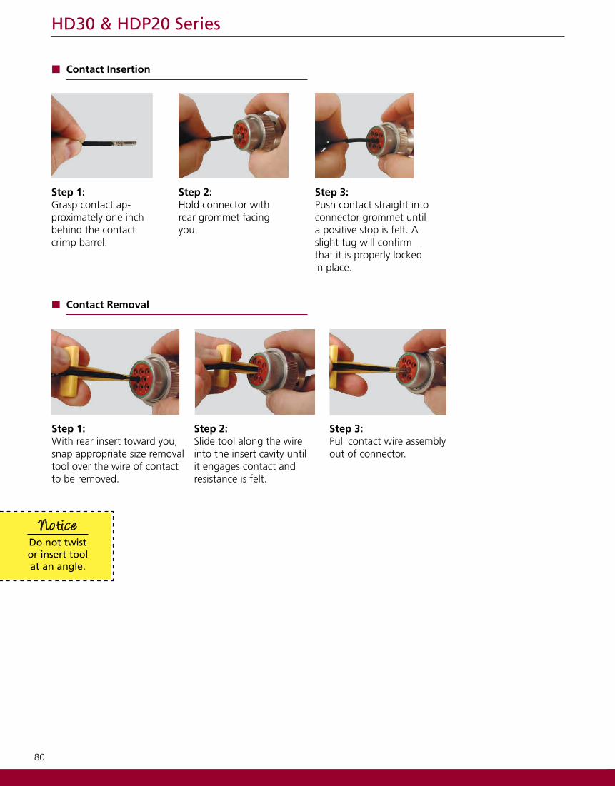
Step 1:Grasp contact ap-proximately one inch behind the contact crimp barrel.
Step 2:Hold connector with rear grommet facing you.
Step 3:Push contact straight into connector grommet until a positive stop is felt. A slight tug will confirm that it is properly locked in place.
Contact Insertion
Step 1:With rear insert toward you, snap appropriate size removal tool over the wire of contact to be removed.
Step 2:Slide tool along the wire into the insert cavity until it engages contact and resistance is felt.
Step 3:Pull contact wire assembly out of connector.
Contact Removal
Do not twist or insert tool at an angle.
Notice