Embed Size (px)
Citation preview
Website: www.luxielectronics.com Email: [email protected]
Document name: HDCP and EDID Demystified Revision: 1.00 Date: 12/12/2012 Copyright © 2012 Luxi Electronics Corp. All rights reserved
HDCP and EDID Demystified
Xiaozheng Lu, CEO, Luxi Electronics Corp
Introduction:
In HDMI, both HDCP and EDID data are sent through DDC lines using I2C protocol. I2C specs state that the combined DDC line capacitance cannot exceed 400 pF. HDMI loosens it to 700 pF but a typical 7.5 m (25’) long HDMI cable alone already has a DDC capacitance more than 700 pF. Therefore, the majority of the HDMI systems installed in the pro AV industry do not meet the I2C specs. This is the root cause of most problems. In the HDMI Demystified series of whitepapers, I concentrated on the digital signal Cliff Effect and its impact in digital product design, installation, and marketing. Now I am writing this whitepaper to tackle the most confusing, yet most important aspects of the digital products: the HDCP and EDID, and the closely related DDC and I2C. In our survey, 1 in 7 installed digital systems fail in the field initially. The puzzling phenomenal is that often after installers return the individual products to the manufacturers only to be told by that nothing is wrong with the products. Even more puzzling, the installers sometimes can fix the problem in one system by replacing brand A product with brand B, yet in another system by replacing brand B with brand A. It defies normal logic.
The non-technical descriptions: 4 terms in 1 picture HDCP, EDID, DDC, and I2C are highly technical terms. For those who do not have time or do not want to know too much about them, I will try to explain them from this picture in the next page. First, the official name explanations: HDCP: High-bandwidth Digital Content Protection EDID: Extended Display Identification Data DDC: Display Data Channel I2C: Inter Integrated Circuit (reads as “eye square see”) Here’s what they do:
Website: www.luxielectronics.com Email: [email protected]
Document name: HDCP and EDID Demystified Revision: 1.00 Date: 12/12/2012 Copyright © 2012 Luxi Electronics Corp. All rights reserved
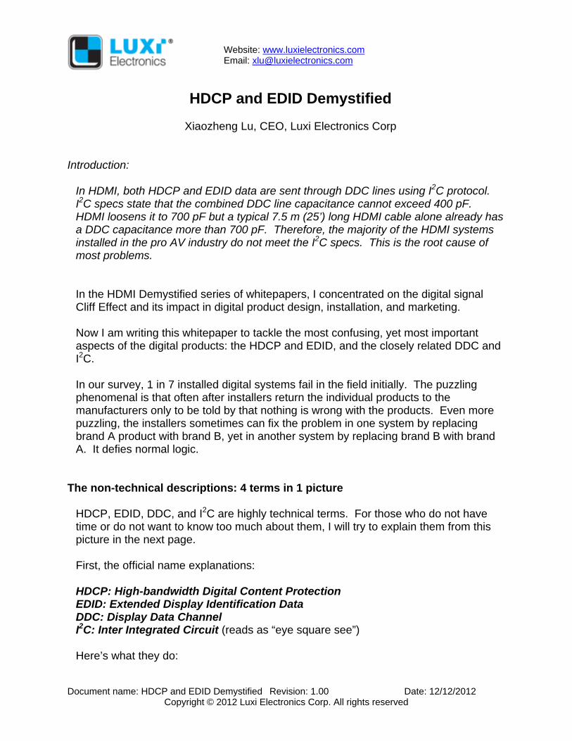
Inside the multi pins of the DVI or HDMI interface, there is one pair of wires called DDC. The DDC carries two kinds of data: HDCP and EDID. EDID is the data that a display tells the source about its resolution, refresh rate, color space, etc. so the source can generate the requested signal to match. HDCP is the copyright data. First, the source requests the HDCP key from the display and validates it. Then the source device sends the encrypted audio video content over the 4 TMDS pairs and the decryption keys over the DDC. The DDC connects multiple devices on the same pair of wires. I2C is the protocol chosen by the DVI and HDMI to manage this multi-device two-way communication.
Now let’s use the real life analogy to look at these 4 terms again in reference to the picture above. DDC is the one lane road. HDCP and EDID are two types of cargos carried by the cars. The I2C is the traffic control police. Many (or a majority) of the problems that installers experience in the field are caused by the I2C protocol chosen by DVI then HDMI. It works perfectly for communications between IC chips inside a product (as the I2C name suggested) but not as much for communications between multiple devices with long cables in between. As a result,
Website: www.luxielectronics.com Email: [email protected]
Document name: HDCP and EDID Demystified Revision: 1.00 Date: 12/12/2012 Copyright © 2012 Luxi Electronics Corp. All rights reserved
communication collisions between devices often happen much like two cars on a one-lane street directed by a blind police in the picture above. When the EDID data is corrupted, the screen would show a wrong color, wrong size, wrong position, green or pink screen, etc. When the HDCP data is corrupt, there would be no picture, a flashing screen, popping sound, etc. Some manufacturers came out with an EDID minder type of product that records the EDID from the display and then plays it back to the source. This is not a clean fix and will not work with HDCP. Another solution is to change the communication timing to avoid collision. This fixes both EDID and HDCP. If you still want to know more, read on.
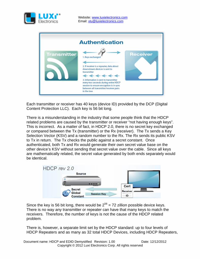
HDCP: High-bandwidth Digital Content Protection HDCP was developed by Intel in 1999 and the current revision is 2.0. It is used for audio video content protection on many digital formats like HDMI, DisplayPort, GVIF, DVI, DLI, UDI, IP, WHDI, TCP/IP, USB, etc. HDCP classifies all devices as HDCP transmitters, HDCP receivers, or HDCP repeaters. The HDCP transmitter is the “boss” because it holds the content. It decides which receivers to send to and how to send the contents. The repeater is the middle manager: it reports to the transmitter and manages the receivers. The HDCP transmitter manages 3 functions: 1) Authentication: It verifies the receiver’s public key certificate, checks locality
(more for wireless transmission to make sure the receiver is in this house and not the neighbor’s house), and exchanges session key.
2) Encryption: After authentication, the transmitter uses its HDCP cipher engine and the shared session key to create a stream of encrypted data that can only be decrypted by the receiver. The receiver uses its HDCP cipher engine and its copy of the session key to decrypt the content. The receiver also sends verification information back to the transmitter every 2 seconds to ensure the encryption is in sync. You probably have experienced the 2 seconds flash when the system is not working right. Now you know the reason.
3) Revocation: The transmitter also checks the receiver’s key against a black list (revoked key list) updated and distributed in media like DVD pressings. Once a receiver’s key is found to be revoked, that receiver can no longer receive the copy protected content.
Website: www.luxielectronics.com Email: [email protected]
Document name: HDCP and EDID Demystified Revision: 1.00 Date: 12/12/2012 Copyright © 2012 Luxi Electronics Corp. All rights reserved
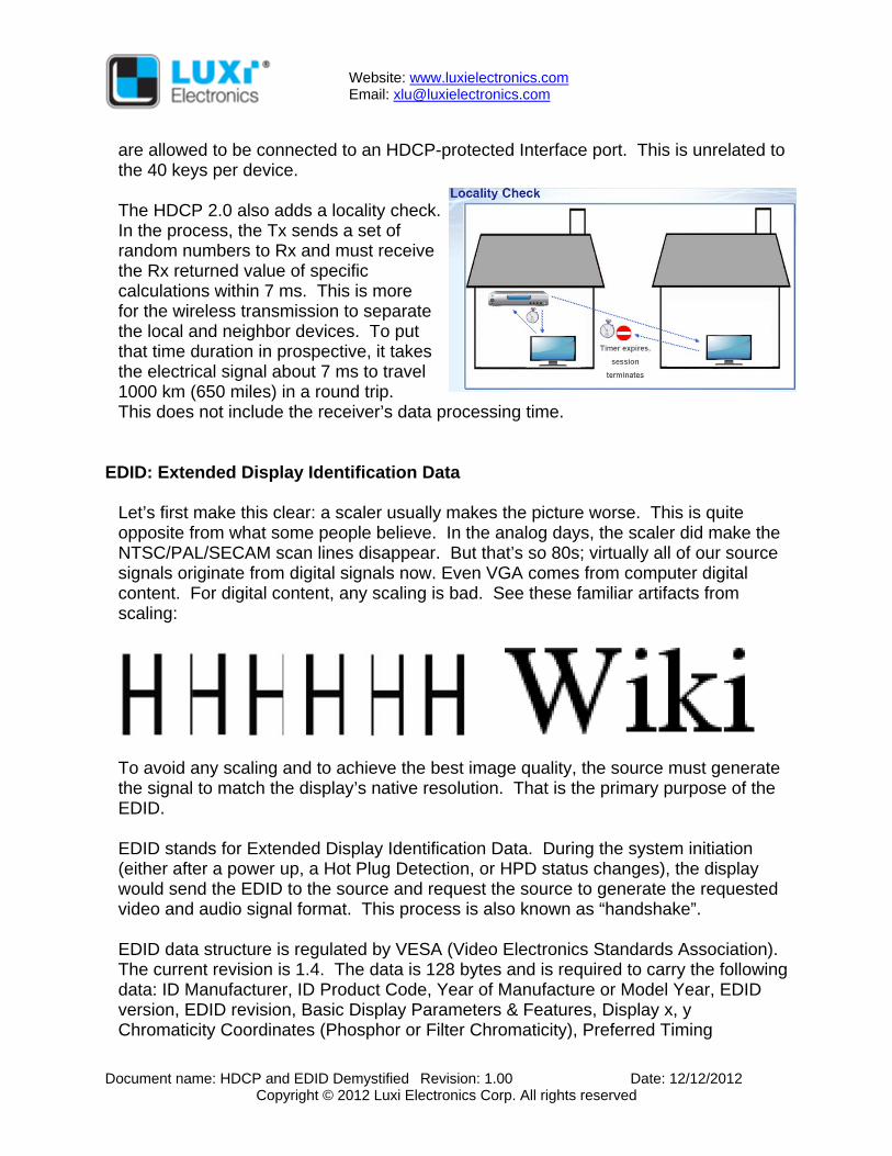
Each transmitter or receiver has 40 keys (device ID) provided by the DCP (Digital Content Protection LLC). Each key is 56 bit long. There is a misunderstanding in the industry that some people think that the HDCP related problems are caused by the transmitter or receiver “not having enough keys”. This is incorrect. As a matter of fact, in HDCP 2.0, there is no secret key exchanged or compared between the Tx (transmitter) or the Rx (receiver). The Tx sends a Key Selection Vector (KSV) and a random number to the Rx. The Rx sends its public KSV to Tx in return. The Tx checks the public against a secret constant. Once authenticated, both Tx and Rx would generate their own secret value base on the other device’s KSV without sending that secret value over the cable. Since all keys are mathematically related, the secret value generated by both ends separately would be identical.
Since the key is 56 bit long, there would be 256 = 72 zillion possible device keys. There is no way any transmitter or repeater can have that many keys to match the receivers. Therefore, the number of keys is not the cause of the HDCP related problem. There is, however, a separate limit set by the HDCP standard: up to four levels of HDCP Repeaters and as many as 32 total HDCP Devices, including HDCP Repeaters,
Website: www.luxielectronics.com Email: [email protected]
Document name: HDCP and EDID Demystified Revision: 1.00 Date: 12/12/2012 Copyright © 2012 Luxi Electronics Corp. All rights reserved
are allowed to be connected to an HDCP-protected Interface port. This is unrelated to the 40 keys per device. The HDCP 2.0 also adds a locality check. In the process, the Tx sends a set of random numbers to Rx and must receive the Rx returned value of specific calculations within 7 ms. This is more for the wireless transmission to separate the local and neighbor devices. To put that time duration in prospective, it takes the electrical signal about 7 ms to travel 1000 km (650 miles) in a round trip. This does not include the receiver’s data processing time.
EDID: Extended Display Identification Data Let’s first make this clear: a scaler usually makes the picture worse. This is quite opposite from what some people believe. In the analog days, the scaler did make the NTSC/PAL/SECAM scan lines disappear. But that’s so 80s; virtually all of our source signals originate from digital signals now. Even VGA comes from computer digital content. For digital content, any scaling is bad. See these familiar artifacts from scaling:
To avoid any scaling and to achieve the best image quality, the source must generate the signal to match the display’s native resolution. That is the primary purpose of the EDID. EDID stands for Extended Display Identification Data. During the system initiation (either after a power up, a Hot Plug Detection, or HPD status changes), the display would send the EDID to the source and request the source to generate the requested video and audio signal format. This process is also known as “handshake”. EDID data structure is regulated by VESA (Video Electronics Standards Association). The current revision is 1.4. The data is 128 bytes and is required to carry the following data: ID Manufacturer, ID Product Code, Year of Manufacture or Model Year, EDID version, EDID revision, Basic Display Parameters & Features, Display x, y Chromaticity Coordinates (Phosphor or Filter Chromaticity), Preferred Timing
Website: www.luxielectronics.com Email: [email protected]
Document name: HDCP and EDID Demystified Revision: 1.00 Date: 12/12/2012 Copyright © 2012 Luxi Electronics Corp. All rights reserved
Descriptor Block, Extension flag etc. VESA defines most of the computer video parameters in the EDID. CEA (Consumer Electronics Association) on the other hand regulates the data of HD video and audio parameters in the CEA-861-D standard. The HDMI standard calls out the CEA-861-D Extension 3 data, which includes: Video Data Block, Audio Data Block, Speaker Allocation Data Block, Vendor Specific Data Block, Colorimetry Data Block and Video Capability Data Block. The data is very comprehensive and includes the resolution, refresh rate, position, blanking, color space, format, audio format, encoding format, channels, effects, sample rate, etc, etc. You probably would know more about the monitor by reading the EDID line by line than the monitor designer himself! In short, EDID is a display to source data that defines what signals the source needs to send. Unlike the HDCP communication happens every 2 seconds, the EDID communication only happens once at system initiation.
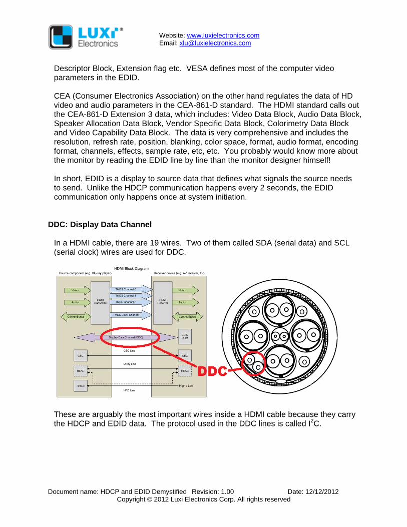
DDC: Display Data Channel In a HDMI cable, there are 19 wires. Two of them called SDA (serial data) and SCL (serial clock) wires are used for DDC.
These are arguably the most important wires inside a HDMI cable because they carry the HDCP and EDID data. The protocol used in the DDC lines is called I2C.
Website: www.luxielectronics.com Email: [email protected]
Document name: HDCP and EDID Demystified Revision: 1.00 Date: 12/12/2012 Copyright © 2012 Luxi Electronics Corp. All rights reserved
I2C: Inter Integrated Circuit (This section is highly technical and is intended for engineers)
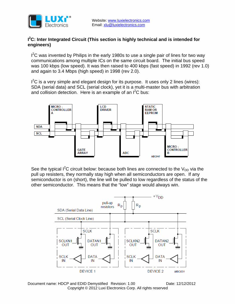
I2C was invented by Philips in the early 1980s to use a single pair of lines for two way communications among multiple ICs on the same circuit board. The initial bus speed was 100 kbps (low speed). It was then raised to 400 kbps (fast speed) in 1992 (rev 1.0) and again to 3.4 Mbps (high speed) in 1998 (rev 2.0). I2C is a very simple and elegant design for its purpose. It uses only 2 lines (wires): SDA (serial data) and SCL (serial clock), yet it is a multi-master bus with arbitration and collision detection. Here is an example of an I2C bus:
See the typical I2C circuit below: because both lines are connected to the VDD via the pull up resisters, they normally stay high when all semiconductors are open. If any semiconductor is on (short), the line will be pulled to low regardless of the status of the other semiconductor. This means that the “low” stage would always win.
Website: www.luxielectronics.com Email: [email protected]
Document name: HDCP and EDID Demystified Revision: 1.00 Date: 12/12/2012 Copyright © 2012 Luxi Electronics Corp. All rights reserved
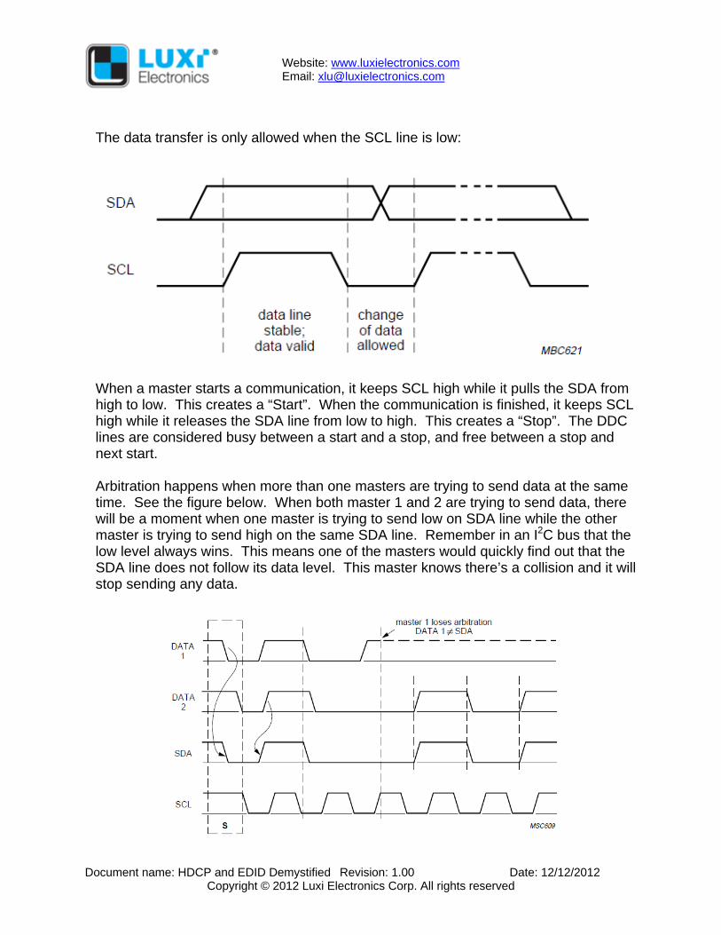
The data transfer is only allowed when the SCL line is low:
When a master starts a communication, it keeps SCL high while it pulls the SDA from high to low. This creates a “Start”. When the communication is finished, it keeps SCL high while it releases the SDA line from low to high. This creates a “Stop”. The DDC lines are considered busy between a start and a stop, and free between a stop and next start. Arbitration happens when more than one masters are trying to send data at the same time. See the figure below. When both master 1 and 2 are trying to send data, there will be a moment when one master is trying to send low on SDA line while the other master is trying to send high on the same SDA line. Remember in an I2C bus that the low level always wins. This means one of the masters would quickly find out that the SDA line does not follow its data level. This master knows there’s a collision and it will stop sending any data.
Website: www.luxielectronics.com Email: [email protected]
Document name: HDCP and EDID Demystified Revision: 1.00 Date: 12/12/2012 Copyright © 2012 Luxi Electronics Corp. All rights reserved
You can see that the timing is super critical in the I2C bus because everything is based on the accurate timing, the data sending, start, stop, acknowledgment and sync (I did not discuss them here due to low relevancy to the topic), and arbitration. The capacitance will slow down the high/low stage transition thus altering the timing observed by multiple devices on the lines. That is why I2C specs clearly define the bus capacitance of each line to ground must be no more than 400 pF. This is easily achievable for multiple ICs on the same PCB which is what the I2C was designed for.
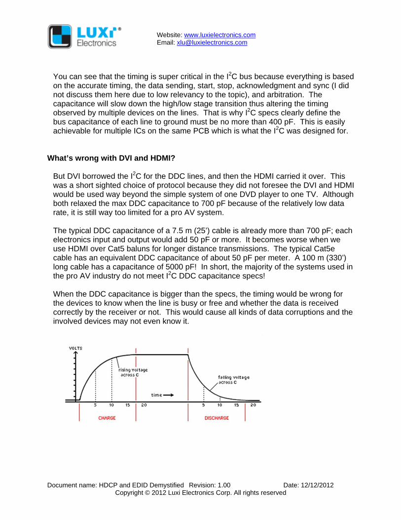
What’s wrong with DVI and HDMI? But DVI borrowed the I2C for the DDC lines, and then the HDMI carried it over. This was a short sighted choice of protocol because they did not foresee the DVI and HDMI would be used way beyond the simple system of one DVD player to one TV. Although both relaxed the max DDC capacitance to 700 pF because of the relatively low data rate, it is still way too limited for a pro AV system. The typical DDC capacitance of a 7.5 m (25’) cable is already more than 700 pF; each electronics input and output would add 50 pF or more. It becomes worse when we use HDMI over Cat5 baluns for longer distance transmissions. The typical Cat5e cable has an equivalent DDC capacitance of about 50 pF per meter. A 100 m (330’) long cable has a capacitance of 5000 pF! In short, the majority of the systems used in the pro AV industry do not meet I2C DDC capacitance specs! When the DDC capacitance is bigger than the specs, the timing would be wrong for the devices to know when the line is busy or free and whether the data is received correctly by the receiver or not. This would cause all kinds of data corruptions and the involved devices may not even know it.
Website: www.luxielectronics.com Email: [email protected]
Document name: HDCP and EDID Demystified Revision: 1.00 Date: 12/12/2012 Copyright © 2012 Luxi Electronics Corp. All rights reserved
What are the symptoms of the DDC data collision? Because the DDC lines carry both HDCP and EDID data, the symptoms of the data collision depend on which data is corrupted. If the error is at the initial HDCP key exchange bits, then the screen would be black If the error is at the de-encryption confirmation bits, then the picture on screen
would be cut off after 2 seconds or flashes in a 2 seconds interval If the error is at the EDID screen resolution bits, then the image on the screen
would be in the wrong size or position If the error is at the EDID video format (RGB or YCrCb) bits, then the screen would
be blue, pink or other abnormal colors If the error is at the EDID audio format bits, then the sound would pop or cut in and
out
Do these symptoms look or sound familiar to you? I am sure you have seen them in the past! Now you know what caused them.
What are the solutions? The ultimate solution is for the HDMI and DVI organizations to make major specification revisions to change the I2C protocol to another protocol that fits the large multi-device systems. Luxi has presented a proposal to HDMI LLC that would use a new protocol while maintaining backwards compatibility with the existing products. Before this kind of major specs change happens, what can we do now? There are 3 methods now to approach the problems from different angles. 1) EDID minders: Remember we discussed how the EDID works: it is a one time
and one way communication. The display sends the EDID data to the source at the system initiation (power up). Several manufacturers make EDID minders. Basically they are small data recorders. You connect this device with the display, record its EDID data, and then connect this device to the source device. From there on the source would talk to this device locally instead of the display through the system to obtain the EDID. It works with DVI because there is no HDCP data. This won’t work with HDMI because the HDCP is a two way communications ongoing constantly in a 2 seconds interval. The EDID minders cannot record and playback the HDCP data.
2) DDC accelerators: Several IC manufacturers have developed ICs to reshape the
DDC data rising and falling edges to reduce the timing delay caused by the DDC capacitors charging and discharging; see the figure in the next page:
Website: www.luxielectronics.com Email: [email protected]
Document name: HDCP and EDID Demystified Revision: 1.00 Date: 12/12/2012 Copyright © 2012 Luxi Electronics Corp. All rights reserved
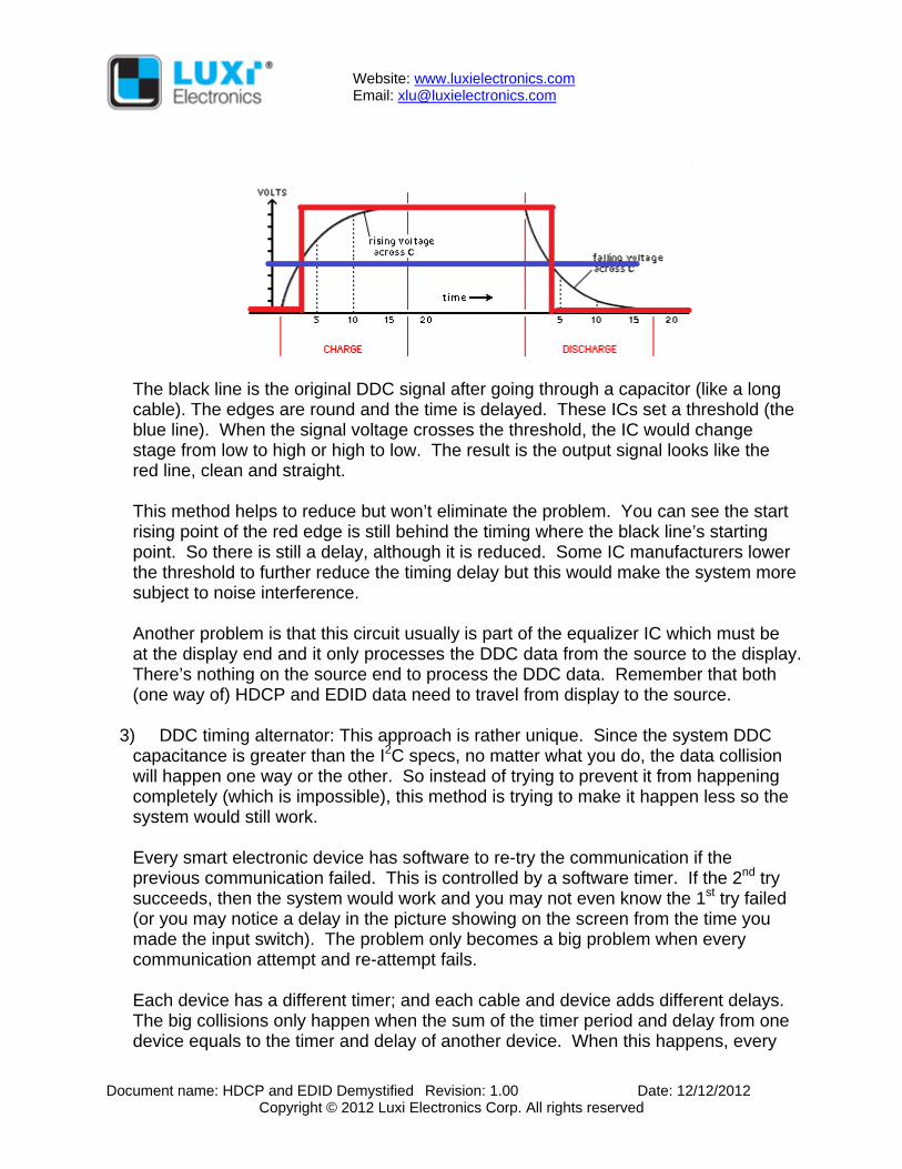
The black line is the original DDC signal after going through a capacitor (like a long cable). The edges are round and the time is delayed. These ICs set a threshold (the blue line). When the signal voltage crosses the threshold, the IC would change stage from low to high or high to low. The result is the output signal looks like the red line, clean and straight. This method helps to reduce but won’t eliminate the problem. You can see the start rising point of the red edge is still behind the timing where the black line’s starting point. So there is still a delay, although it is reduced. Some IC manufacturers lower the threshold to further reduce the timing delay but this would make the system more subject to noise interference. Another problem is that this circuit usually is part of the equalizer IC which must be at the display end and it only processes the DDC data from the source to the display. There’s nothing on the source end to process the DDC data. Remember that both (one way of) HDCP and EDID data need to travel from display to the source.
3) DDC timing alternator: This approach is rather unique. Since the system DDC
capacitance is greater than the I2C specs, no matter what you do, the data collision will happen one way or the other. So instead of trying to prevent it from happening completely (which is impossible), this method is trying to make it happen less so the system would still work. Every smart electronic device has software to re-try the communication if the previous communication failed. This is controlled by a software timer. If the 2nd try succeeds, then the system would work and you may not even know the 1st try failed (or you may notice a delay in the picture showing on the screen from the time you made the input switch). The problem only becomes a big problem when every communication attempt and re-attempt fails. Each device has a different timer; and each cable and device adds different delays. The big collisions only happen when the sum of the timer period and delay from one device equals to the timer and delay of another device. When this happens, every
Website: www.luxielectronics.com Email: [email protected]
Document name: HDCP and EDID Demystified Revision: 1.00 Date: 12/12/2012 Copyright © 2012 Luxi Electronics Corp. All rights reserved
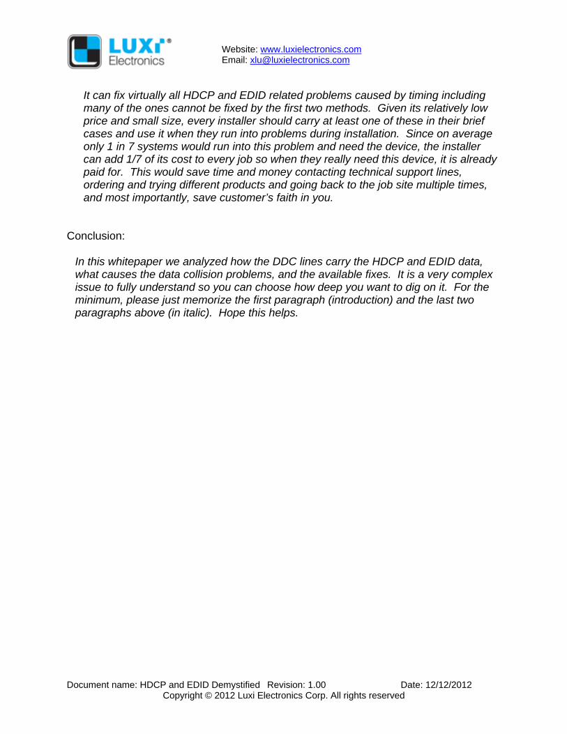
attempt and re-attempt of the communication would fail because both devices retry at the same time interval thus they would collide again and again. It is like a dart hitting the bull’s eye on a target: it only happens in certain timing and delay combination of a given system. When any device or cable has changed, the timer plus delay would not be the exact the same between the 2 devices anymore, so the repeated collision would not happen and system would work again. It’s equivalent to moving the target away to any direction so the dart would not hit the bull’s eye. You must have experienced this phenomenal: you replace a device from brand A to brand B and the system works, so you are sure that device from brand A is faulty and return it to manufacturer A and swear never to use it again. Yet in another system when brand B does not work, you replace it with brand A and now the system works. Now you start cursing brand B and fall in love with brand A. In both cases, both manufacturers of brand A and B tell you the returned products have no trouble in their labs. Now you know why. But you know once a system is installed, it is very difficult to replace devices to a different brand. It would take time, money, customer’s anger, and your returned trip to the job site to make the system work. Luxi Electronics’ CHD-110 Communicator product is a timing alternator that would change the system timing to avoid the repeated collision in a system; just like to move the target away so the dart won’t hit the bull’s eye anymore. It’s very easy to apply thanks to the pigtail female to male configuration; you just need to insert it inline in your system and you can also easily try different insertion point until the problem is fixed. It’s a fully HDCP compliant product with its own HDCP keys. It draws power from the source as the 1st option; if not enough power from the source, an optional external 5 V power supply can be plugged in.
Website: www.luxielectronics.com Email: [email protected]
Document name: HDCP and EDID Demystified Revision: 1.00 Date: 12/12/2012 Copyright © 2012 Luxi Electronics Corp. All rights reserved
It can fix virtually all HDCP and EDID related problems caused by timing including many of the ones cannot be fixed by the first two methods. Given its relatively low price and small size, every installer should carry at least one of these in their brief cases and use it when they run into problems during installation. Since on average only 1 in 7 systems would run into this problem and need the device, the installer can add 1/7 of its cost to every job so when they really need this device, it is already paid for. This would save time and money contacting technical support lines, ordering and trying different products and going back to the job site multiple times, and most importantly, save customer’s faith in you.
Conclusion: In this whitepaper we analyzed how the DDC lines carry the HDCP and EDID data, what causes the data collision problems, and the available fixes. It is a very complex issue to fully understand so you can choose how deep you want to dig on it. For the minimum, please just memorize the first paragraph (introduction) and the last two paragraphs above (in italic). Hope this helps.


![User Manual 4K Linker Rev 0 - Home | HDFury.com · [Custom/GUI use EDID]: Pick and use EDID from a selection of available EDID tables (see p.11) or load any EDID bank of your choice](https://img.pdfslide.net/doc/110x75/5f1c9545d02e5227d236dcb7/user-manual-4k-linker-rev-0-home-customgui-use-edid-pick-and-use-edid-from.jpg)