Embed Size (px)
Citation preview
International Journal of Applied Engineering Research ISSN 0973-4562 Volume 12, Number 16 (2017) pp. 6076-6090
© Research India Publications. http://www.ripublication.com
6076
HDFS Write Operation Using Fully Connected Digraph DataNode Network
Topology
B. Purnachandra Rao
Research Scholar, Department of Computer Science &Engineering, Acharya Nagarjuna University,
Guntur, Andhra Pradesh, 522510, India.
ANU College of Engineering &Technology, NH16, Nagarjuna Nagar, Acharya Nagarjuna University,
Guntur, Andhra Pradesh 522510, India.
Orcid Id: 0000-0002-4770-2830
Dr. N. Nagamalleswara Rao
Professor, Department of Information Technology, RVR.& JC College of Engineering & Technology, Guntur,
Andhra Pradesh, 522019, India.
Abstract
Hadoop is an open source implementation of the MapReduce
Framework in the realm of distributed processing. A Hadoop
cluster is having the capability to handle large amounts of
data. To handle massive scale data, Hadoop exploits the
Hadoop Distributed File System termed as HDFS. Client will
write data to DataNodes by taking the blocks info from
NameNode . The DataNodes containing the blocks will be
connected in pipeline fashion. While writing the data if
DataNode /network fails the failed DataNode will be
removed from the pipeline. Based on the available DataNodes
in the cluster the new DataNode will be included in the
pipeline. If there are very less number of spare nodes in the
cluster users may experience an unusually high rate of
pipeline failures since it is impossible to find new DataNodes
for replacement. If network failure happend ,the data packet
cannot be reached to the target DataNode since they are
connected in pipeline fashion. If each DataNode is connected
to each other DataNode then there will not be any issue with
network failure since they have number of paths through
other DataNodes. In pipeline connectivity the copy operation
will take longertime , where as in DataNode is having direct
connection to all other DataNodes , it will take very less time
because datapacket is not required to traverse through all other
DataNodes to reach the end DataNode . In this paper we will
address the network failure issues among the DataNodes and
reducing the copy operation time to copy data packet to
DataNodes which are in pipeline by fully connected digraph
network topology. Using this topology network complexity
will be high, but we can reduce the time to copy one data
packet to all replica locations (DataNodes) and nullify the
network failure issues among the DataNodes.
Keywords: Hadoop Distributed File System (HDFS),
NameNode , DataNode, Replica, Rackawareness, Data
Packet, Data Packet Transfer Time, Pipeline, Fully Connected
Digrapgh Network Topology.
INTRODUCTION
Hadoop Distributed File System (HDFS)[1] is a distributed
file system that is developed to deploy on low cost commodity
hardware to store very large datasets reliably and has high
degree of fault tolerance and also stream those data sets at
high bandwidth for user applications to run on commodity
hardware. It is a master/slave architecture where master is
called NameNode and slaves are called DataNodes. HDFS
has many similarities with existing distributed file system, but
they are very different. A distributed file system consists of
single NameNode and multiple data nodes and provides
availability and reliability by holding multiple replicas of data.
NameNode and Datanode interactions are high while reading
or writing to file when there is a heavy work load which will
decrease the performance. The system having the NameNode
acts as the master server. NameNode maintains the metadata
pertaining to the file system, such as the file hierarchy and the
block locations for each file. It also performs file system
operations such as closing, opening and renaming files and
directories. Each storage node runs a process called a
Datanode that manages the blocks on that host, and these are
controlled by a master NameNode process running on a
separate host. To meet exponential storage demands of
Hadoop[1], MapReduce[5], Dryad[10] and HPCC(High-
Performance Computing Cluster)[12] frameworks disk based
file systems is the suitable file system.A requested task can be
completed efficiently, when the computation takes place near
the data. In case of huge datasets are involved, operation
reduces the network traffic and increases the throughput.
Hadoop distributed file system (HDFS) [6] has the potential to
International Journal of Applied Engineering Research ISSN 0973-4562 Volume 12, Number 16 (2017) pp. 6076-6090
© Research India Publications. http://www.ripublication.com
6077
store huge amounts of data since it is having huge number of
nodes in each cluster. Need to pay some time penalty while
retrieving or keeping the data in DataNode . There are
different components to reduce disk access latencies like
scheduling jobs on same node that consists of associated data,
in addition, information is copied to different nodes in
number ways to improve the performance in job completion
time. A fully connected network is a communication network
in which each of the nodes is connected to each other. In
graph theory it is known as a complete graph. There will be
number of alternative paths from one DataNode to each other
DataNode in the cluster which includes only replication
factor number of DataNodes in the connection process. So we
can use the number of alternative paths from one DataNode
to other DataNode incase of any failure in the existing path
between two DataNodes. Even copy operation also will take
less time since we can apply parallel copy process among the
datnodes from the starting DataNode which is connected
directly from the client to all other DataNodes which are part
of the replication factor.The new features of the proposed
method are reducing the copy operation time among the
DataNodes and providing the number of alternative paths to
reach the target DataNode in case of network failure.In the
existing process we are configuring the parameters
dfs.client.block.write.replace-datanode-on-
failure.enable,dfs.client.block.write.replace-datanode-on-
failure.policy. Once we start using the proposed architecture
we no need to change the DataNodes in case of network
failure , instead of that we can reach the DataNode using
alternative paths among the DataNodes. This paper describes
the concepts such as literature survey on the existing
mechanism using for HDFS memory operation, description
of HDFS components , the problem in the existing
architecture , proposed architecture using fully connected
digraph DataNode network topology , the implementation
and the evaluation process using the simulation results . This
paper presents the mechanism to reduce the copy operation
time to DataNodes (replication of datapackets) and to nullify
the network failure issues among the DataNodes by using
fully connected digraph network topology[4].
LITERATURE REVIEW
HDFS with Linear DataNode Connectivity
HDFS system is implemented on Linux machine. When a
client makes a request for reading some HDFS data, it first
contacts the NameNode to find out the first few blocks of the
file it wants to read. The NameNode returns the addresses of
all DataNodes that store a copy of those first few blocks,
ranking the DataNodes in order of their closeness to the client.
The client then reads the data from the DataNodes in the
preferential order presented to it. Should the first DataNode
fail during the read say because the DataNode is dead , the
client automatically connects to the next DataNode in the list
and reads the block. When the client reads the block, it also
verifies that the blocks current checksum is the same as the
original checksum calculated when the block was first stored
on disk. If the checksum differs, again the client will move to
a different DataNode in the list to read the data. The client
also informs the NameNode that it found a potentially corrupt
block and the NameNode will replicate the corrupt block to
another DataNode. A DataNode will verify checksums for all
blocks it stores every three weeks. If the read request
emanated from one of the clusters DataNodes, the first choice
of the client would be to see if that DataNode itself can satisfy
the read request, without having to go to a non-local
DataNode. As the client starts reading through the first few
blocks, it requests that the NameNode send it the locations
for the next set of data blocks. The NameNode will send the
best list of DataNodes for each data block. In Client write
operation the client will create the file and connect to the
NameNode for that namespace. The NameNode after
verifying that the file doesn't already exist and the client has
sufficient permissions to create the file, records the new file in
its metadata and sends the block name and list of DataNodes
to the client. The list of DataNodes is called a pipeline. The
pipeline specifies the DataNodes on which the clients can
place the block replicas. The file the client wants to write out
to HDFS is split into blocks and these blocks are stored on
HDFS on various DataNodes. The client connects to the first
DataNode in the pipeline and starts writing the data blocks on
that node. the first DataNode will connect to the second
DataNode in the list and forward it the data blocks as it
receives them. The second DataNode inturn connects to and
forwards the data to the next DataNode in the pipeline. When
all three (by default) replicas are completely written to the
client, an acknowledgement packet is relayed through the
pipeline of DataNode to the client, to indicate that the block
was successfully written to all nodes. The client willstart
writing the next block at this point.When all block replicas are
written, the block is committed in the edit log by the
NameNode and marked as "written." When the client
completes writing data to the file, it closes the file. This
requires that all the file's blocks have been replicated the
minimum number of times. The client may have to wait to
close the file if there are any DataNode failures in the process.
The client informs the NameNode that the file writing was
successfully completed. The writing of the block replicas is
done asynchronously. The client doesn't have to send the data
blocks it's writing to all the DataNodes. It just sends them to
one of the DataNodes in the list provided by the NameNode ,
and it's the responsibility of that DataNode to send the data
blocks along to the other DataNodes in the pipeline. Each
DataNode will also save a checksum of each data block it
stores. When this block is read , its checksum is verified to
ensure that the block is complete and isn't corrupt. The
NameNode creates metadata from the block reports it
receives from the DataNodes. HDFS stores the data blocks
such that the availability of one or more nodes won't cause a
International Journal of Applied Engineering Research ISSN 0973-4562 Volume 12, Number 16 (2017) pp. 6076-6090
© Research India Publications. http://www.ripublication.com
6078
data loss. Hadoop automatically replicates any lost blocks.
Data replication ensures both availability and data locality,
which helps enforce a guiding principle of Hadoop, which is
to bring processing to the data and not the other way round, as
it is in traditional database systems. The existing system is
using dfs.client.block.write.replace-datanode-on-
failure.enable,dfs.client.block.write.replace-datanode-on-
failure.policy parameters to maintain the fault tolerance even
when the DataNode /network failure while writing or reading
data from DataNodes. DFSClientwill request for data blocks
from the NameNode . Once the client gets the list of data
blocks , client will open the Out stream for write operation.
Data will be written to nearest DataNode (block) , and this
DataNode will be connected to other DataNodes (number of
DataNodes based on the replication factor) in pipeline
fashion[7-8]. If there is a DataNode /network failure issue in
the write operation (pipeline), DFSClient will remove the
failed DataNode from the pipeline and then resume write
operation with the remaining DataNodes. As a result of this
operation, the number of DataNodes in the pipeline will go
down. The feature is to add new DataNodes to the pipeline.
When the number of nodes in the cluster is (cluster size)
extremely small, example number of nodes is 3 or less, cluster
administrators may want to set the
policydfs.client.block.write.replace-datanode-on-
failure.enable to NEVER in the default configuration file
(hdfs-default.xml) or disable this feature. Otherwise, users
may face an unusually high rate of pipeline failures since it is
impossible to find new DataNodes for replacement. If we
have four nodes and a replication factor of 3, each block will
have a replica on three of the live nodes in the cluster. If a
node dies, the blocks living on the other nodes are unaffected,
but any blocks with a replica on the dead node will need a
new replica created. However, with only three live nodes,
each node will hold a replica of every block. If a second node
fails, the situation will result into under-replicated blocks and
Hadoop does not have anywhere to put the additional replicas.
Since both remaining nodes already hold a replica of each
block, their storage utilization does not increase. DataNodes
will be connected (based on the blocks from the Namespace)
using pipeline. In the existing architecture to deliver the
packet it needs to traverse through all the DataNodes to reach
the last DataNode (based on the replication factor we need to
decide last number).Refer with: Fig. 1, While writing the data
if DataNode /network fails the failed DataNode will be
removed from the pipeline. Adding the new DataNode to
pipeline will depend on the available nodes in the cluster. The
problem in the existing architecture is users may experience
an unusually high rate of pipeline failures since it is
impossible to find new DataNodes for replacement. The time
required to send the data packet and getting the
acknowledgement back to source DataNode will take longer
time since the DataNodes are connected in linear pipeline
fashion.
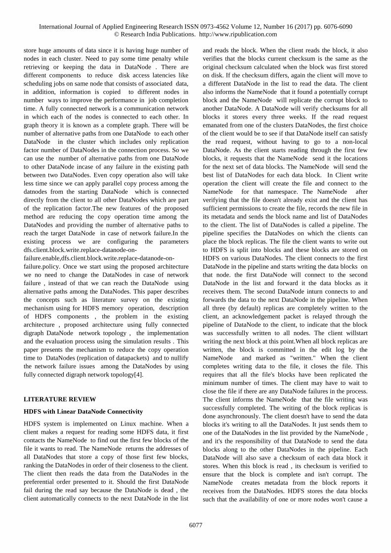
Figure 1: DataNode pipeline connectivity.
If we consider one millisecond is for inter rack DataNode
packet transfer and 0.75 millisecond is for intra rack
DataNode packet transfer, then (replication factor is 4,
DataNode2 and DataNode3 are in second rack, where as
DataNode1 and DataNode4 are in rack1 and rack4
respectively) 1 millisecond to reach to second DataNode ,
0.75 to reach from DataNode2 to DataNode3 and 1
millisecond from DataNode3 to DataNode4. So the total time
is 1+0.75+1 = 2.75 milliseconds. The same is applicable for
acknowledgement transfer as well.So total 5.50 milliseconds
required to complete one packet copy operation with
replication factor 4. Referwith: Table 1for the time taken
for copy operation of one packet using different replication
factors.
Table 1: Packet Transfer time with different replicationfactors
Replication Factor Packet Transfer(ms)
3 3.5
4 5.5
5 7.5
6 9.5
7 11.5
International Journal of Applied Engineering Research ISSN 0973-4562 Volume 12, Number 16 (2017) pp. 6076-6090
© Research India Publications. http://www.ripublication.com
6079
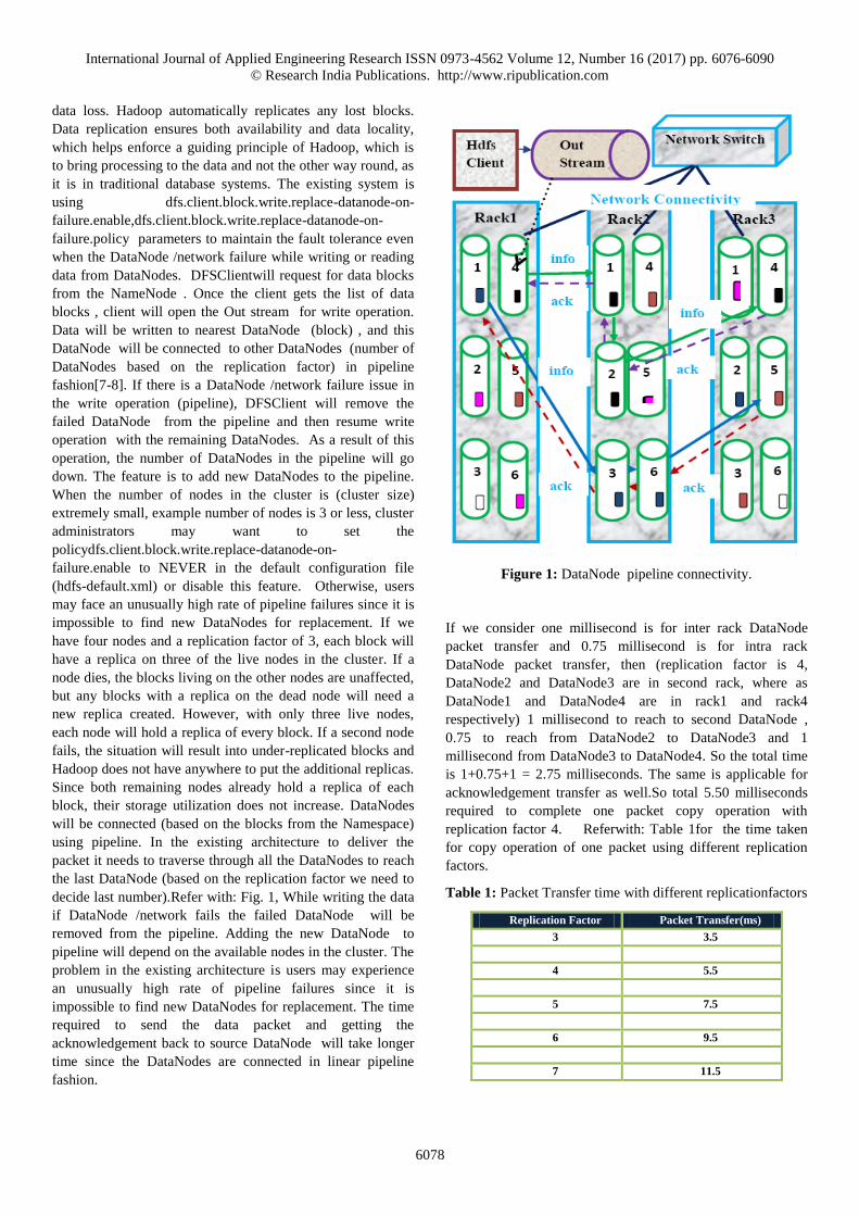
The time is growing up while increasing the replication factor,
because the DataNodes will be connected in pipeline
fashion[3] (one DataNode to another till the last DataNode
and the number of DataNodes in the pipeline depends on the
replication factor). For files which are frequently accessed or
critical, setting the replication factor improves their tolerance
against faults and increases the read bandwidth. In the existing
system we are using the parameter
dfs.client.block.write.replace-datanode-on-failure.enable[3]
to replace the DataNode in case of DataNode /network
failure. If the number of spare nodes are less or unavailable ,
then we need to set the parameter to NEVER so that we can
externally informing to file system that , there will not be any
node replacement in case of any network/node failure. This is
having the limitation on number of DataNodes available in the
cluster. Refer with: Graph 1 for the time status while
increasing the replication factor.
Graph 1: ReplicationFactor Vs PacketTransfer time
NameNode
NameNode is the centrepiece of Hadoop Distributed File
System. NameNode is also known as the Master. NameNode
only stores the metadata of HDFS – such as the file hierarchy
and the block locations for each file. NameNode does not
store the actual data or the dataset where as the data will be
stored in DataNodes. NameNode is usually configured with a
lot of memory (RAM). NameNode knows the list of the
blocks and its location for any given file in HDFS. It is easy
for NameNode to construct the file from blocks since it is
having knowledge on blocks and locations. NameNode is
having namespace consists of files and directories . Inodes
will be used here to represent the files and directories. Inode is
having the file permissions , modification and access time ,
disk space and namespace info.The file content is devided into
blocks (typically 128MB) each block of file is independently
replicated at multiple DataNodes. NameNode is having the
info related to mapping of file blocks to DataNodes. When a
client makes a request for reading some HDFS data, it first
contacts the NameNode to findout the locations of the first
few blocks of file it wants to read. Whereas in write operation
the set of DataNodes to host the block replicas will be allotted
by NameNode to client upon the request from the client. In
the next phase the write operation to DataNodes in pipeline
fashion[7-8] will be performed by client . The file the client
wants to write out to HDFS is split into blocks and these
blocks are stored on HDFS on various DataNodes. The client
connects to the first DataNode in the pipeline and starts
writing the data blocks on that node.
DataNode
In a Hadoop cluster, which consists of multiple nodes, one or
more of the nodes will act as a master nodes[13]. The master
nodes run key Hadoop services such as the NameNode and
the Resource manager. The rest of the servers in a Hadoop
cluster are worker nodes, commonly referred to as DataNodes.
It's these nodes that actually store the data blocks. The
DataNode performs the functions (based on the directives
sent by the NameNode ) like providing the block storage by
storing blocks on the local file system, fulfilling the
read/write requests from the clients who want to work with
the data stored on the DataNodes, creating and deleting
datablocks, replicating data across the cluster, keeping in
touch with NameNode by sending periodic block reports and
heartbeats. A heartbeat confirms the DataNode is alive and
healthy ,and a block report shows the blocks being managed
by the DataNode. The file in a file system will be partitioned
into one or more segments and/or stored in individual data
nodes. These are called as blocks. The default block size is
128MB, but it can be increased using HDFS configuration.
NameNode will be having handshake at startup with all
DataNodes. In the handshaking process the namespace ID and
software version of DataNode will be verified. In the
successful case of matching, the communication will start
with DataNode . In the case of mismatch DataNode will
automatically shuts down. DataNodes are not connected
directly to the NameNode but communicate with them as the
need occurs. When the DataNode is started (or restarted), it
registers with the NameNode to let it know that it's available
to handle HDFS read and write operations.A recently initiated
DataNode with no namespace ID can join the cluster and it
will get the group's (cluster) namespace ID. Each DataNode
persistently saves its unique storage ID, which help to
recognize the DataNode after restarting it with different port
3.5
5.5
7.5
9.5
11.5
0
5
10
3 4 5 6 7
Transfer
Time(ms)
Replication Factor
DataPacket Pipeline Transfer
Time
Packet Transfer(ms)
International Journal of Applied Engineering Research ISSN 0973-4562 Volume 12, Number 16 (2017) pp. 6076-6090
© Research India Publications. http://www.ripublication.com
6080
or IP address. All DataNodes periodically(every three seconds
by default) send a heartbeat containing statistical usage
information for that DataNode to the NameNode . This
heartbeat lets the NameNode that it can send commands such
as block replication or deletion to the DataNodes. If the
NameNode does not receive a heartbeat for a long time, it
requests an immediate block report from the DataNode. If the
NameNode does not recognize the DataNode, either because
the NameNode has restarted , or because the network
connection with the DataNode has timed out, it asks the
DataNode to register again.
If a DataNode fails to send its periodic heartbeat even after a
long time (such as ten minutes), the NameNode will mark
that DataNode as dead and issues commands to other
DataNodes to replicate the data stored on the dead DataNode,
to makeup the replication factor of the blocks to the
configured number of replicas. NameNode sends instructions
to DataNodes as acknowledgement to heartbeat. Refer
with:Fig.2 for HDFS Architecture.
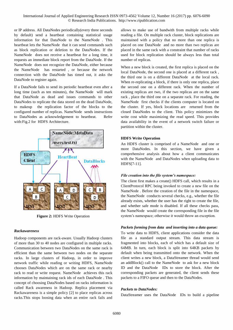
Figure 2: HDFS Write Operation
Rackawareness
Hadoop components are rack-aware. Usually Hadoop clusters
of more than 30 to 40 nodes are configured in multiple racks.
Communication between two DataNodes on the same rack is
efficient than the same between two nodes on the separate
racks. In large clusters of Hadoop, in order to improve
network traffic while reading or writing HDFS, NameNode
chooses DataNodes which are on the same rack or nearby
rack to read or write request. NameNode achieves this rack
information by maintaining rack ids of each DataNode . This
concept of choosing DataNodes based on racks information is
called Rack awareness in Hadoop. Replica placement via
Rackawareness is a simple policy [2] to place replicas across
racks.This stops loosing data when an entire rack fails and
allows to make use of bandwith from multiple racks while
reading a file. On multiple rack cluster, block replications are
maintained with a policy that no more than one replica is
placed on one DataNode and no more than two replicas are
placed in the same rack with a constraint that number of racks
used for block replication should be always less than total
number of replicas.
When a new block is created, the first replica is placed on the
local DataNode, the second one is placed at a different rack ,
the third one is on a different DataNode at the local rack.
When re-replicating a block, if there is only one replica, place
the second one on a different rack. When the number of
existing replicas are two, if the two replicas are on the same
rack , place the third one on a separate rack. For reading, the
NameNode first checks if the clients computer is located on
the cluster. If yes, block locations are returned from the
closed DataNodes to the client. This policy minimizes the
write cost while maximizing the read speed. This provides
data availability in the event of a network switch failure or
partition within the cluster.
HDFS Write Operation
An HDFS cluster is comprised of a NameNode and one or
more DataNodes. In this section, we have given a
comprehensive analysis about how a client communicates
with the NameNode and DataNodes when uploading data to
HDFS[7-11].
File creation into the file system’s namespace:
The client first makes a create() HDFS call, which results in a
ClientProtocol RPC being invoked to create a new file on the
NameNode . Before the creation of the file in the namespace,
the NameNode conducts several checks, e.g., whether the file
already exists, whether the user has the right to create the file,
and whether safe mode is disabled. If all these checks pass,
the NameNode would create the corresponding file in the file
system’s namespace; otherwise it would throw an exception.
Packets forming from data and inserting into a data queue:
To write data to HDFS, client applications consider the data
file as a standard output stream. This data stream is
fragmented into blocks, each of which has a default size of
64MB. In turn, each block is split into 64KB packets by
default when being transmitted onto the network. When the
client writes a new block, a DataStreamer thread would send
an addBlock() call to the NameNode to ask for a new block
ID and the DataNode IDs to store the block. After the
corresponding packets are generated, the client sends these
packets to a FIFO queue and then to the DataNodes.
Packets to DataNodes:
DataStreamer uses the DataNode IDs to build a pipeline
International Journal of Applied Engineering Research ISSN 0973-4562 Volume 12, Number 16 (2017) pp. 6076-6090
© Research India Publications. http://www.ripublication.com
6081
between the client and these DataNodes, streams the packets
to the first DataNode in the pipeline one by one, and stores
these packets into another queue called ACK queue in case
some DataNodes require retransmitting due to packet loss.
When the first DataNode receives a packet, it verifies the
packet’s checksum, stores the packet, and transfers it to the
next DataNode in the pipeline. This procedure will repeat
until the packet reaches the last DataNode at the end of the
pipeline.
Sending acknowledgement (ACK) to the client:
When the last DataNode obtains the packet, it would send an
ACK through the pipeline in a reverse order. The client has a
thread called PacketResponder that is responsible for
receiving response ACKs. If the PacketResponder thread
receives a packet ACK from all DataNodes, it removes this
packet from the ACK queue.
Close the output stream:
When the client has flushed all data into the output stream, it
calls close() on the stream, and waits for all packets’ ACKs.
Completing file write:
When all packets’ ACKs are received by the PacketResponder
thread, it wakes up the client. The client would send a
complete signal to the NameNode to complete this file write
operation. Refer with: Fig.3 for HDFS write operation.
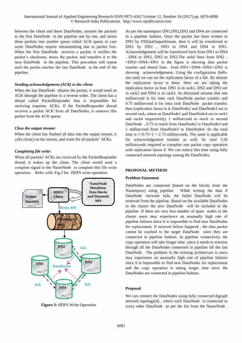
Figure 3: HDFS Write Operation
As per the namespace DN1,DN2,DN3 and DN4 are connected
in a pipeline fashion. Once the packet has been written to
DN2 by FSDataOutputStream, then it will be transferred to
DN3 by DN2 , DN3 to DN4 and DN4 to DN1.
Acknowledgement will be transferred back from DN1 to DN4
, DN4 to DN3, DN3 to DN2.The solid lines from DN2 -
>DN3->DN4->DN1 in the figure is showing data packet
transfer and dotted lines from DN1->DN4->DN3->DN2 is
showing acknowledgement. Using the configuration (hdfs-
site.xml) we can set the replication factor of a file. By default
the replication factor is three. Here we are taking the
replication factor as four. DN1 is in rack1, DN2 and DN3 are
in rack2 and DN4 is in rack3. As discussed assume that one
millisecond is for inter rack DataNode packet transfer and
0.75 millisecond is for intra rack DataNode packet transfer,
then (replication factor is 4, DataNode2 and DataNode3 are in
second rack, where as DataNode1 and DataNode4 are in rack1
and rack4 respectively) 1 millisecond to reach to second
DataNode , 0.75 to reach from DataNode2 to DataNode3 and
1 millisecond from DataNode3 to DataNode4. So the total
time is 1+0.75+1 = 2.75 milliseconds. The same is applicable
for acknowledgement transfer as well. So total 5.50
milliseconds required to complete one packet copy operation
with replication factor 4. We can reduce this time using fully
connected network topology among the DataNodes.
PROPOSAL METHOD
Problem Statement
DataNodes are connected (based on the blocks from the
Namespace) using pipeline. While writing the data if
DataNode /network fails, the failed DataNode will be
removed from the pipeline. Based on the available DataNodes
in the cluster the new DataNode will be included in the
pipeline. If there are very less number of spare nodes in the
cluster users may experience an unusually high rate of
pipeline failures since it is impossible to find new DataNodes
for replacement. If network failure happend , the data packet
cannot be reached to the target DataNode since they are
connected in pipeline fashion. In pipeline connectivity the
copy operation will take longer time ,since it needs to traverse
through all the DataNodes connected in pipeline till the last
DataNode . The problem in the existing architecture is users
may experience an unusually high rate of pipeline failures
since it is impossible to find new DataNodes for replacement
and the copy operation is taking longer time since the
DataNodes are connected in pipeline fashion.
Proposal
We can connect the DataNodes using fully connected digraph
network topology[4] , where each DataNode is connected to
every other DataNode as per the list from the NameNode .
HDFS
Client
NameNode
MetaData:
Data blocks
and Datanode
info
FSOutputSt
ream
DN1
DN4
DN3
DN2
Output
FileHDFS
Write API
Ack
Ack Ack
DataPacket
International Journal of Applied Engineering Research ISSN 0973-4562 Volume 12, Number 16 (2017) pp. 6076-6090
© Research India Publications. http://www.ripublication.com
6082
We can have number of alternative paths in case of network
failure in the current part and we can improvethe write
operation performance by decreasing the operation time using
the new architecture. DFSClient will request for data blocks
from the NameNode . Once the client gets the list of data
blocks , client will open the Out stream for write operation.
Data will be written to nearest DataNode (block) , and this
DataNode will be connected to other DataNodes (number of
DataNodes based on the replication factor) in pipeline fashion.
If there is a network failure in the write pipeline, the operation
cannot be completed . To avoid this connectivity issues , we
can use the DataNodes using fully connected digraph network
topology[4] , where each DataNode is connected to every
other DataNode as per the list from the NameNode . Total
number of edges are n(n-1) if there are n DataNodes in the
pipeline. Each DataNode is having n-1 outgoing edges to
connect to n-1 DataNodes.The existing architecture each
DataNode is having 2(n-1) edges where as n-1 edges for
datapacket copy operation and the other n-1 for
acknowledgement. Solid lines are datapacket transfer
operation and dotted lines for acknowledgement operation.
Here the dotted lines mentioned with double direction.
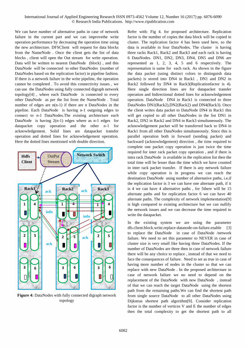
Figure 4: DataNodes with fully connected digraph network
topology
Refer with: Fig 4. for proposed architecture. Replication
factor is the number of copies the data block will be copied in
cluster. The replication factor 4 has been used here, so the
data is available in four DataNodes. The cluster is having
three racks Rack1, Rack2 and Rack3 and each rack is having
6 DataNodes. DN1, DN2, DN3, DN4, DN5 and DN6 are
represented as 1, 2, 3, 4, 5 and 6 respectively. The
representation is same for each rack. As shown in the figure
the data packet (using distinct colors to distinguish data
packets) is stored into DN4 in Rack1 , DN1 and DN2 in
Rack2 followed by DN4 in Rack3(Replicationfactor is 4).
Here single direction lines are for datapacket transfer
operation and bidirectional dotted lines for acknowledgement
operation. DataNode DN4 in Rack1 is connected to three
DataNodes DN1(Rack2),DN2(Rack2) and DN4(Rack3). Once
the client writes data packet to DataNode DN4 in Rack1 this
will get copied to all other DataNodes in the list DN1 in
Rack2, DN2 in Rack2 and DN4 in Rack3 simultaneously. The
acknowledgement packet will be transferred back to DN4 in
Rack1 from all other DataNodes simultaneously. Since this is
parallel operation both in forward (sending packet) and
backward (acknowledgement) direction , the time required to
complete one packet copy operation is just twice the time
required for inter rack packet copy operation , and if there is
intra rack DataNode is available in the replication list then the
total time will be lesser than the time which we have counted
in inter rack packet transfer. If there is any network failure
while copy operation is in progress we can reach the
destination DataNode using number of alternative paths, i.e,if
the replication factor is 3 we can have one alternate path, if it
is 4 we can have 4 alternative paths , for 5there will be 15
alternate paths and for replication factor 6 we can have 40
alternate paths. The complexity of network implementation[9]
is high compared to existing architecture but we can nullify
the network issues and we can decrease the time required to
write the datapacket.
In the existing system we are using the parameter
dfs.client.block.write.replace-datanode-on-failure.enable [3]
to replace the DataNode in case of DataNode /network
failure. We need to set this parameter to NEVER in case of
cluster size is very small like having three DataNodes. If the
number of DataNodes are three then in case of network failure
there will be any choice to replace , instead of that we need to
face the consequences of failure. Need to set as true in case of
having more number of nodes in the cluster so that we can
replace with new DataNode . In the proposed architecture in
case of network failure we no need to depend on the
replacement of the DataNode with new DataNode , instead
of that we can reach the target DataNode using the shortest
path from the remaining paths.We can find the shortest path
from single source DataNode to all other DataNodes using
Dijkstras shortest path algorithm[9]. Consider replication
factor is the number of vertices V and E the number of edges
then the total complexity to get the shortest path to all
4
5
Rack1 Rack2 Rack3
3
2
1 4
6
1
3
2
4 1
5
6 3 6
5 2
Network Switch
1
OutPut
Stream
Hdfs
Client
4
5 ack
ack
ack ack
info info
International Journal of Applied Engineering Research ISSN 0973-4562 Volume 12, Number 16 (2017) pp. 6076-6090
© Research India Publications. http://www.ripublication.com
6083
DataNodes from single source is O(E Log V) and there will be
number of unused paths in each copy operation , these are the
two extra complexities which we need to face to nullify the
network failure issues. Please find the pseudo code for
Dijkstra's Algorithm.
Foreach node set distance[node]=HIGH
TraversedNodes=empty
UnTraversedNodes=empty
AddstartNodetoUnTraversedNodes
distance[startNode]=0
while(UnTraversedNodes is not empty){
assessmentNode=findShortDistanceNode(UnTraversedNodes)
remove assessmentNode fromUnTraversedNodes
add assessmentNode to TraversedNodes
assessedNeighbours(assessmentNode)
}
findShortDistanceNode(UnTraversedNodes){
find the node with the minimum distance in
UnTraversedNodes and return it.
}
assessedNeighbours(assessmentNode){
For Each target node which can be reached via
and edge from assessmentNode
AND which is not in TraversedNodes{
edgeDistance=getDistance(edge(assessmentNode,
targetNode)){
newDistance=distance[assessmentNode]+edgeDistance
if(distance[targetNode] >newDistance){
distance[targetNode] = newDistance
add targetNode to UnTraversedNodes}}}}
Dijkstra algorithm partitions all nodes into two distinct sets:
untraversedNodes and traversedNodes. Initially all nodes are
in the untraversedNodessets, e.g. they must be still evaluated.
A node is moved to the traversedNodesset if a shortest path
from the source to this node has been found. Initially
thedistance of each node to the source is set to a very high
value. First only the source is in the set of untraversedNodes.
The algorithms runs until the unsettledNodesnumber becomes
zero. In each iteration it selects the node with the lowest
distance from the source out of the untraversedNodes. It reads
all edges which are outgoing from the source and evaluates
for each destination node, using the edges which are not yet
settled, if the distance which is already calculated from the
source to this node can be reduced while using the selected
edge. If this is going to happen then the distance is updated
and the node is added to the nodes which need evaluation.
This is how can have number of alternative paths so that users
will escape from experiencing an unusually high rate of
pipeline failures.
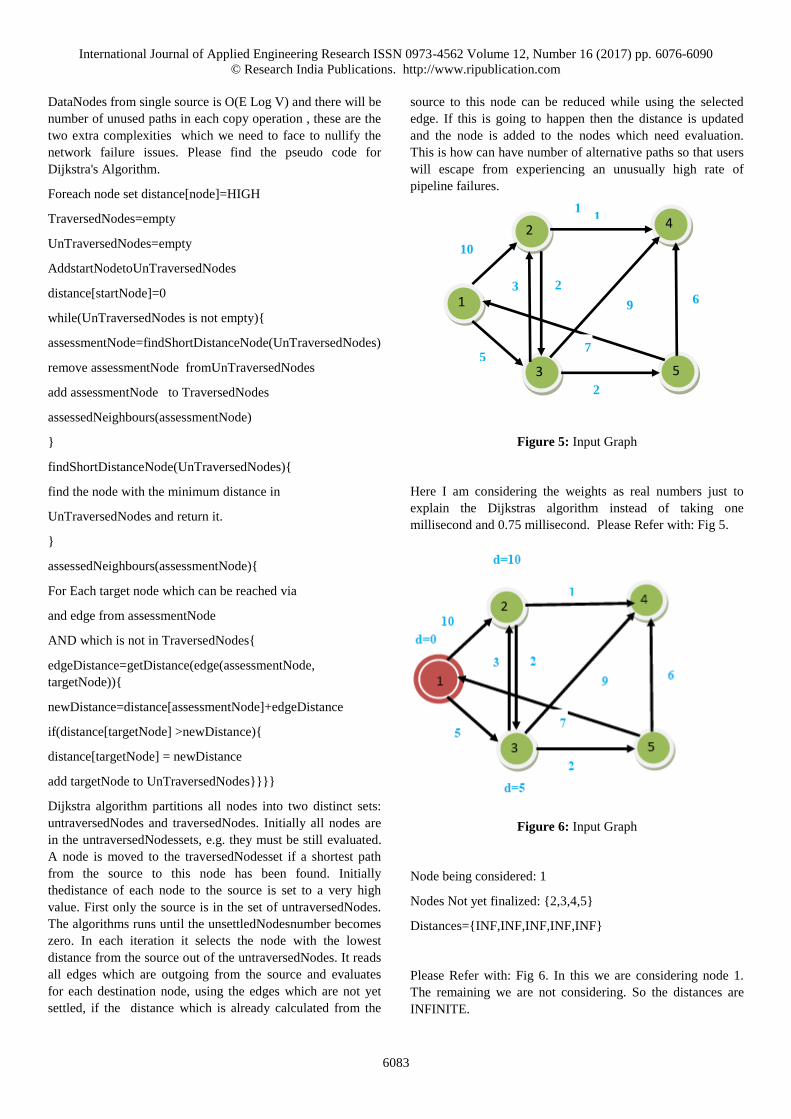
Figure 5: Input Graph
Here I am considering the weights as real numbers just to
explain the Dijkstras algorithm instead of taking one
millisecond and 0.75 millisecond. Please Refer with: Fig 5.
Figure 6: Input Graph
Node being considered: 1
Nodes Not yet finalized: {2,3,4,5}
Distances={INF,INF,INF,INF,INF}
Please Refer with: Fig 6. In this we are considering node 1.
The remaining we are not considering. So the distances are
INFINITE.
1
3 5
4 2
2
5
10
2 3
1
6 9
7
1
International Journal of Applied Engineering Research ISSN 0973-4562 Volume 12, Number 16 (2017) pp. 6076-6090
© Research India Publications. http://www.ripublication.com
6084
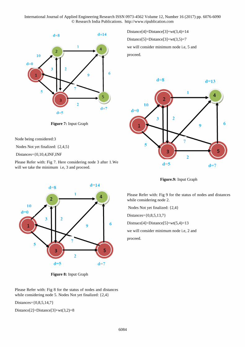
Figure 7: Input Graph
Node being considered:3
Nodes Not yet finalized: {2,4,5}
Distances={0,10,4,INF,INF
Please Refer with: Fig 7. Here considering node 3 after 1.We
will we take the minimum i.e, 3 and proceed.
Figure 8: Input Graph
Please Refer with: Fig 8 for the status of nodes and distances
while considering node 5. Nodes Not yet finalized: {2,4}
Distances={0,8,5,14,7}
Distance[2]=Distance[3]+wt(3,2)=8
Distance[4]=Distance[3]+wt(3,4)=14
Distance[5]=Distance[3]+wt(3,5)=7
we will consider minimum node i.e, 5 and
proceed.
Figure.9: Input Graph
Please Refer with: Fig 9 for the status of nodes and distances
while considering node 2.
Nodes Not yet finalized: {2,4}
Distances={0,8,5,13,7}
Distnace[4]=Distance[5]+wt(5,4)=13
we will consider minimum node i.e, 2 and
proceed.
International Journal of Applied Engineering Research ISSN 0973-4562 Volume 12, Number 16 (2017) pp. 6076-6090
© Research India Publications. http://www.ripublication.com
6085
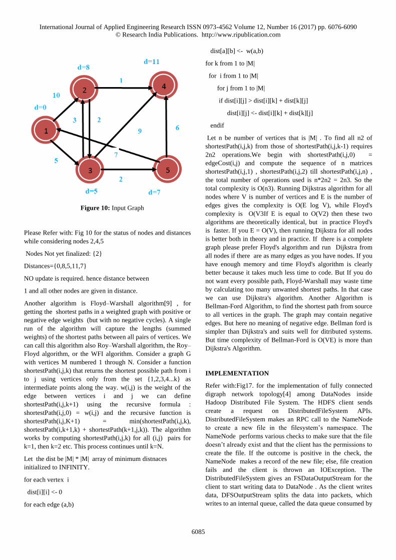
Figure 10: Input Graph
Please Refer with: Fig 10 for the status of nodes and distances
while considering nodes 2,4,5
Nodes Not yet finalized: {2}
Distances={0,8,5,11,7}
NO update is required. hence distance between
1 and all other nodes are given in distance.
Another algorithm is Floyd–Warshall algorithm[9] , for
getting the shortest paths in a weighted graph with positive or
negative edge weights (but with no negative cycles). A single
run of the algorithm will capture the lengths (summed
weights) of the shortest paths between all pairs of vertices. We
can call this algorithm also Roy–Warshall algorithm, the Roy–
Floyd algorithm, or the WFI algorithm. Consider a graph G
with vertices M numbered 1 through N. Consider a function
shortestPath(i,j,k) that returns the shortest possible path from i
to j using vertices only from the set {1,2,3,4...k} as
intermediate points along the way. w(i,j) is the weight of the
edge between vertices i and j we can define
shortestPath(i,j,k+1) using the recursive formula :
shortestPath(i,j,0) = w(i,j) and the recursive function is
shortestPath(i,j,K+1) = min(shortestPath(i,j,k),
shortestPath(i,k+1,k) + shortestPath(k+1,j,k)). The algorithm
works by computing shortestPath(i,j,k) for all (i,j) pairs for
k=1, then k=2 etc. This process continues until k=N.
Let the dist be |M| * |M| array of minimum distnaces
initialized to INFINITY.
for each vertex i
dist[i][i] <- 0
for each edge (a,b)
dist[a][b] <- w(a,b)
for k from 1 to |M|
for i from 1 to |M|
for j from 1 to |M|
if dist[i][j] > dist[i][k] + dist[k][j]
dist[i][j] <- dist[i][k] + dist[k][j]
endif
Let n be number of vertices that is |M| . To find all n2 of
shortestPath(i,j,k) from those of shortestPath(i,j,k-1) requires
2n2 operations.We begin with shortestPath(i,j,0) =
edgeCost(i,j) and compute the sequence of n matrices
shortestPath(i,j,1) , shortestPath(i,j,2) till shortestPath(i,j,n) ,
the total number of operations used is n*2n2 = 2n3. So the
total complexity is O(n3). Running Dijkstras algorithm for all
nodes where V is number of vertices and E is the number of
edges gives the complexity is O(E log V), while Floyd's
complexity is O(V3If E is equal to O(V2) then these two
algorithms are theoretically identical, but in practice Floyd's
is faster. If you E = O(V), then running Dijkstra for all nodes
is better both in theory and in practice. If there is a complete
graph please prefer Floyd's algorithm and run Dijkstra from
all nodes if there are as many edges as you have nodes. If you
have enough memory and time Floyd's algorithm is clearly
better because it takes much less time to code. But If you do
not want every possible path, Floyd-Warshall may waste time
by calculating too many unwanted shortest paths. In that case
we can use Dijkstra's algorithm. Another Algorithm is
Bellman-Ford Algorithm, to find the shortest path from source
to all vertices in the graph. The graph may contain negative
edges. But here no meaning of negative edge. Bellman ford is
simpler than Dijkstra's and suits well for ditributed systems.
But time complexity of Bellman-Ford is O(VE) is more than
Dijkstra's Algorithm.
IMPLEMENTATION
Refer with:Fig17. for the implementation of fully connected
digraph network topology[4] among DataNodes inside
Hadoop Distributed File System. The HDFS client sends
create a request on DistributedFileSystem APIs.
DistributedFileSystem makes an RPC call to the NameNode
to create a new file in the filesystem’s namespace. The
NameNode performs various checks to make sure that the file
doesn’t already exist and that the client has the permissions to
create the file. If the outcome is positive in the check, the
NameNode makes a record of the new file; else, file creation
fails and the client is thrown an IOException. The
DistributedFileSystem gives an FSDataOutputStream for the
client to start writing data to DataNode . As the client writes
data, DFSOutputStream splits the data into packets, which
writes to an internal queue, called the data queue consumed by
International Journal of Applied Engineering Research ISSN 0973-4562 Volume 12, Number 16 (2017) pp. 6076-6090
© Research India Publications. http://www.ripublication.com
6086
the DataStreamer, which is responsible for requesting the
NameNode to allocate new blocks by picking a list of suitable
DataNodes to store the replicas. Here the DataNodes are
connected in fully connected digraph network topology so the
data packet will be transferred to all DataNodes
simultaneously.
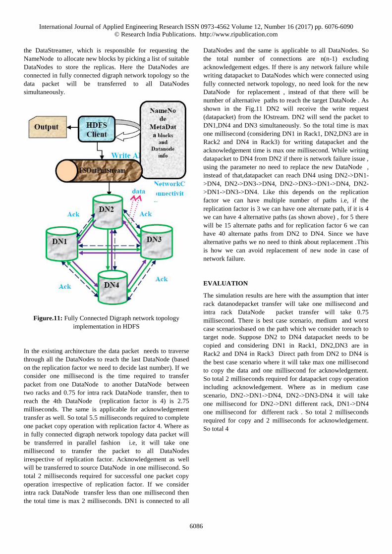
Figure.11: Fully Connected Digraph network topology
implementation in HDFS
In the existing architecture the data packet needs to traverse
through all the DataNodes to reach the last DataNode (based
on the replication factor we need to decide last number). If we
consider one millisecond is the time required to transfer
packet from one DataNode to another DataNode between
two racks and 0.75 for intra rack DataNode transfer, then to
reach the 4th DataNode (replication factor is 4) is 2.75
milliseconds. The same is applicable for acknowledgement
transfer as well. So total 5.5 milliseconds required to complete
one packet copy operation with replication factor 4. Where as
in fully connected digraph network topology data packet will
be transferred in parallel fashion i.e, it will take one
millisecond to transfer the packet to all DataNodes
irrespective of replication factor. Acknowledgement as well
will be transferred to source DataNode in one millisecond. So
total 2 milliseconds required for successful one packet copy
operation irrespective of replication factor. If we consider
intra rack DataNode transfer less than one millisecond then
the total time is max 2 milliseconds. DN1 is connected to all
DataNodes and the same is applicable to all DataNodes. So
the total number of connections are n(n-1) excluding
acknowledgement edges. If there is any network failure while
writing datapacket to DataNodes which were connected using
fully connected network topology, no need look for the new
DataNode for replacement , instead of that there will be
number of alternative paths to reach the target DataNode . As
shown in the Fig.11 DN2 will receive the write request
(datapacket) from the IOstream. DN2 will send the packet to
DN1,DN4 and DN3 simultaneously. So the total time is max
one millisecond (considering DN1 in Rack1, DN2,DN3 are in
Rack2 and DN4 in Rack3) for writing datapacket and the
acknowledgement time is max one millisecond. While writing
datapacket to DN4 from DN2 if there is network failure issue ,
using the parameter no need to replace the new DataNode ,
instead of that,datapacket can reach DN4 using DN2->DN1-
>DN4, DN2->DN3->DN4, DN2->DN3->DN1->DN4, DN2-
>DN1->DN3->DN4. Like this depends on the replication
factor we can have multiple number of paths i.e, if the
replication factor is 3 we can have one alternate path, if it is 4
we can have 4 alternative paths (as shown above) , for 5 there
will be 15 alternate paths and for replication factor 6 we can
have 40 alternate paths from DN2 to DN4. Since we have
alternative paths we no need to think about replacement .This
is how we can avoid replacement of new node in case of
network failure.
EVALUATION
The simulation results are here with the assumption that inter
rack datanodepacket transfer will take one millisecond and
intra rack DataNode packet transfer will take 0.75
millisecond. There is best case scenario, medium and worst
case scenariosbased on the path which we consider toreach to
target node. Suppose DN2 to DN4 datapacket needs to be
copied and considering DN1 in Rack1, DN2,DN3 are in
Rack2 and DN4 in Rack3 Direct path from DN2 to DN4 is
the best case scenario where it will take max one millisecond
to copy the data and one millisecond for acknowledgement.
So total 2 milliseconds required for datapacket copy operation
including acknowledgement. Where as in medium case
scenario, DN2->DN1->DN4, DN2->DN3-DN4 it will take
one millisecond for DN2->DN1 different rack, DN1->DN4
one millisecond for different rack . So total 2 milliseconds
required for copy and 2 milliseconds for acknowledgement.
So total 4
International Journal of Applied Engineering Research ISSN 0973-4562 Volume 12, Number 16 (2017) pp. 6076-6090
© Research India Publications. http://www.ripublication.com
6087
Table 2: Access Time Analysis using Fully
ConectedDataNode Topology.
BestCase Scenario DataNode Connectivity Transfer Time
Rack1 DN1
Rack2 DN2,DN3
Rack3 DN4
DN2->DN4 :
1 ms, different rack
1 +1 : 2ms
(copy+ack)
MediumCase
Scenario
DataNode Connectivity Transfer Time
Rack1 DN1 ,
Rack2 DN2,DN3
Rack3 DN4
DN2->DN1->DN4,
DN2->DN3->DN4
DN2->DN1 : 1 ms
DN1->DN4 :1 ms
DN2->DN3: 0.75ms
same rack
1+1 : 2
2+2:4 (copy+ack)
0.75+1:1.75
1.75+1.75:3.50
(copy+ack)
0.75+0.75:1.5
1.5+1.5=3ms
(copy+ack)
WorstCase
Scenario
DataNode Connectivity Transfer Time
Rack1 DN1
Rack2 DN2,DN3
Rack3 DN4
DN2->DN1->DN3->DN4
DN2->DN3->DN1->DN4
1+1+1:3
3+3 : 6 ms
(copy+ack)
0.75+1+1:2.75
2.75 + 2.75 : 5.50
ms
(copy+ack)
milliseconds in medium case scenario. In the worst case
scenario DN2->DN1->DN3->DN4 (3+3) , DN2->DN3-
>DN1-DN4 (2.75+2.75) total time is max 6 milliseconds and
min 5.5 milliseconds including acknowledgement. Refer
with: Table 2 for the Access Time Analysis using Fully
Connected DataNode Topology. In the linear pipeline
connectivity time required for datapacket copy operation
including acknowledgement is 5.5 milliseconds, which is
almost two times to worst case scenario of fully connected
digraph network topology. Refer with: Table 3 for the results
of linear fashion DataNode pipeline connectivity and the fully
connected digraph network topology with different level of
replication factors using the best casescenario of fully
connected digraph network topology. That means no network
failure and using the direct path from source DataNode to
destination DataNode . In this proposed architecture the time
required to complete one packet copy operation is 2
milliseconds if there are no intra rack DataNodes , and max 2
milliseconds in case of the DataNodes list includes intra rack
DataNodes. Based on the results mentioned here for
replication factor 4 FullyConnectedDataNode Digraph
topology is better than Liner Pipeline data packet transfer
time.
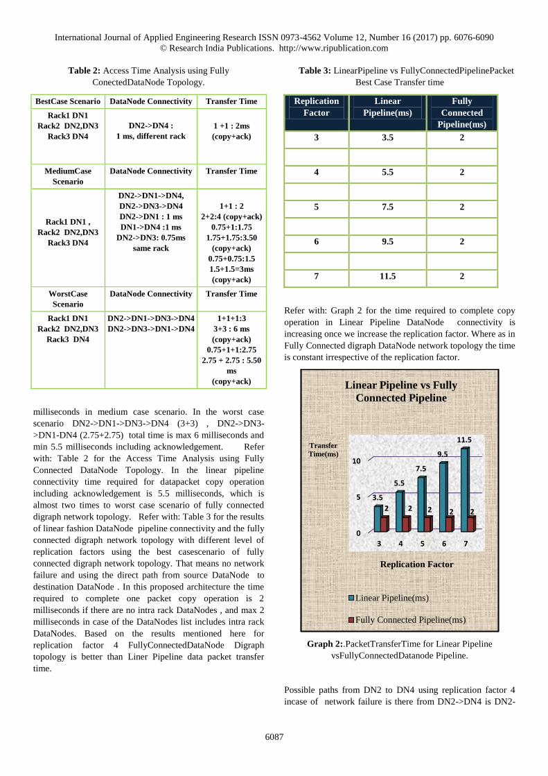
Table 3: LinearPipeline vs FullyConnectedPipelinePacket
Best Case Transfer time
Replication
Factor
Linear
Pipeline(ms)
Fully
Connected
Pipeline(ms)
3 3.5 2
4 5.5 2
5 7.5 2
6 9.5 2
7 11.5 2
Refer with: Graph 2 for the time required to complete copy
operation in Linear Pipeline DataNode connectivity is
increasing once we increase the replication factor. Where as in
Fully Connected digraph DataNode network topology the time
is constant irrespective of the replication factor.
Graph 2:.PacketTransferTime for Linear Pipeline
vsFullyConnectedDatanode Pipeline.
Possible paths from DN2 to DN4 using replication factor 4
incase of network failure is there from DN2->DN4 is DN2-
0
5
10
3 4 5 6 7
3.5
5.5
7.5
9.5
11.5
2 2 2 2 2
Transfer
Time(ms)
Replication Factor
Linear Pipeline vs Fully
Connected Pipeline
Linear Pipeline(ms)
Fully Connected Pipeline(ms)
International Journal of Applied Engineering Research ISSN 0973-4562 Volume 12, Number 16 (2017) pp. 6076-6090
© Research India Publications. http://www.ripublication.com
6088
>DN1->DN4, DN2->DN3->DN4. Refer with: Table 4 for
the results of linear fashion DataNode pipeline connectivity
and the fully connected digraph network topology with
different level of replication factors especially with medium
case scenario of fully connected digraph network topology for
replication factor 4. In this proposed architecture the time
required to complete one packet copy operation from DN2-
>DN1 is 1 millisecond and DN1->DN4 is 1 millisecond. So
total is is 2 milliseconds and including acknowledgement is 4
milliseconds. In case of DN2->DN3->DN4 the total time
including acknowledgement is 3 milliseconds. Based on the
results mentioned here for replication factor 4 Fully
Connected DataNode Digraph topology is better than Liner
Pipeline data packet transfer time.
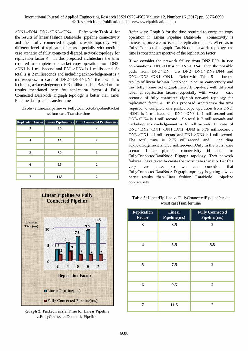
Table 4: LinearPipeline vs FullyConnectedPipelinePacket
medium case Transfer time
Replication Factor Linear Pipeline(ms) Fully Connected Pipeline(ms)
3 3.5 2
4 5.5 3
5 7.5 2
6 9.5 2
7 11.5 2
Graph 3: PacketTransferTime for Linear Pipeline
vsFullyConnectedDatanode Pipeline.
Refer with: Graph 3 for the time required to complete copy
operation in Linear Pipeline DataNode connectivity is
increasing once we increase the replication factor. Where as in
Fully Connected digraph DataNode network topology the
time is constant irrespective of the replication factor.
If we consider the network failure from DN2-DN4 in two
combinations DN1->DN4 or DN3->DN4, then the possible
paths from DN2->DN4 are DN2->DN1->DN3-DN4 and
DN2->DN3->DN1->DN4. Refer with: Table 5 for the
results of linear fashion DataNode pipeline connectivity and
the fully connected digraph network topology with different
level of replication factors especially with worst case
scenario of fully connected digraph network topology for
replication factor 4. In this proposed architecture the time
required to complete one packet copy operation from DN2-
>DN1 is 1 millisecond , DN1->DN3 is 1 millisecond and
DN3->DN4 is 1 millisecond. . So total is 3 milliseconds and
including acknowledgement is 6 milliseconds. In case of
DN2->DN3->DN1->DN4 ,DN2->DN3 is 0.75 millisecond ,
DN3->DN1 is 1 millisecond and DN1->DN4 is 1 millisecond.
The total time is 2.75 millisecond and including
acknowledgement is 5.50 milliseconds.Only in the worst case
scenari Linear pipeline connectivity id equal to
FullyConnectedDataNode Digraph topology. Two network
failures I have taken to create the worst case scenario. But this
very rare case. So we can conculde that
FullyConnectedDataNode Digraph topology is giving always
better results than liner fashion DataNode pipeline
connectivity.
Table 5:.LinearPipeline vs FullyConnectedPipelinePacket
worst caseTransfer time
Replication
Factor
Linear
Pipeline(ms)
Fully Connected
Pipeline(ms)
3 3.5 2
4 5.5 5.5
5 7.5 2
6 9.5 2
7 11.5 2
0
5
10
3 4 5 6 7
3.5
5.5
7.5
9.5
11.5
23
2 2 2
Transfer
Time(ms)
Replication Factor
Linear Pipeline vs Fully
Connected Pipeline
Linear Pipeline(ms)
Fully Connected Pipeline(ms)
International Journal of Applied Engineering Research ISSN 0973-4562 Volume 12, Number 16 (2017) pp. 6076-6090
© Research India Publications. http://www.ripublication.com
6089
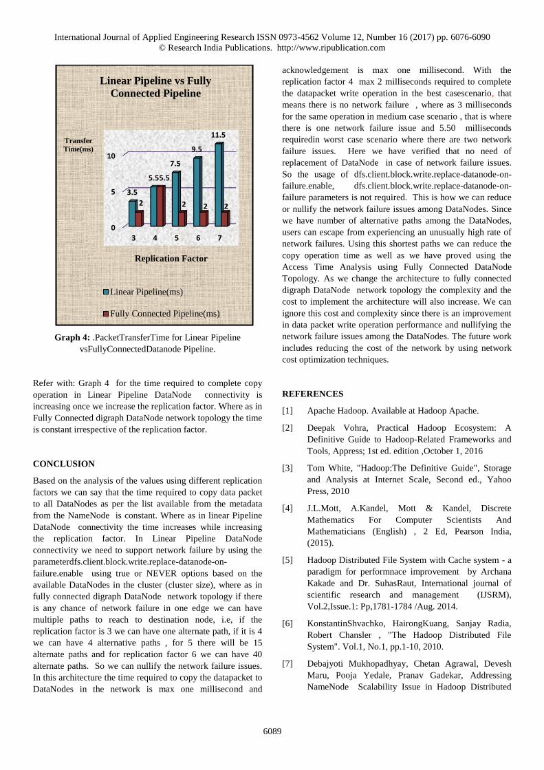
Graph 4: .PacketTransferTime for Linear Pipeline
vsFullyConnectedDatanode Pipeline.
Refer with: Graph 4 for the time required to complete copy
operation in Linear Pipeline DataNode connectivity is
increasing once we increase the replication factor. Where as in
Fully Connected digraph DataNode network topology the time
is constant irrespective of the replication factor.
CONCLUSION
Based on the analysis of the values using different replication
factors we can say that the time required to copy data packet
to all DataNodes as per the list available from the metadata
from the NameNode is constant. Where as in linear Pipeline
DataNode connectivity the time increases while increasing
the replication factor. In Linear Pipeline DataNode
connectivity we need to support network failure by using the
parameterdfs.client.block.write.replace-datanode-on-
failure.enable using true or NEVER options based on the
available DataNodes in the cluster (cluster size), where as in
fully connected digraph DataNode network topology if there
is any chance of network failure in one edge we can have
multiple paths to reach to destination node, i.e, if the
replication factor is 3 we can have one alternate path, if it is 4
we can have 4 alternative paths , for 5 there will be 15
alternate paths and for replication factor 6 we can have 40
alternate paths. So we can nullify the network failure issues.
In this architecture the time required to copy the datapacket to
DataNodes in the network is max one millisecond and
acknowledgement is max one millisecond. With the
replication factor 4 max 2 milliseconds required to complete
the datapacket write operation in the best casescenario, that
means there is no network failure , where as 3 milliseconds
for the same operation in medium case scenario , that is where
there is one network failure issue and 5.50 milliseconds
requiredin worst case scenario where there are two network
failure issues. Here we have verified that no need of
replacement of DataNode in case of network failure issues.
So the usage of dfs.client.block.write.replace-datanode-on-
failure.enable, dfs.client.block.write.replace-datanode-on-
failure parameters is not required. This is how we can reduce
or nullify the network failure issues among DataNodes. Since
we have number of alternative paths among the DataNodes,
users can escape from experiencing an unusually high rate of
network failures. Using this shortest paths we can reduce the
copy operation time as well as we have proved using the
Access Time Analysis using Fully Connected DataNode
Topology. As we change the architecture to fully connected
digraph DataNode network topology the complexity and the
cost to implement the architecture will also increase. We can
ignore this cost and complexity since there is an improvement
in data packet write operation performance and nullifying the
network failure issues among the DataNodes. The future work
includes reducing the cost of the network by using network
cost optimization techniques.
REFERENCES
[1] Apache Hadoop. Available at Hadoop Apache.
[2] Deepak Vohra, Practical Hadoop Ecosystem: A
Definitive Guide to Hadoop-Related Frameworks and
Tools, Appress; 1st ed. edition ,October 1, 2016
[3] Tom White, "Hadoop:The Definitive Guide", Storage
and Analysis at Internet Scale, Second ed., Yahoo
Press, 2010
[4] J.L.Mott, A.Kandel, Mott & Kandel, Discrete
Mathematics For Computer Scientists And
Mathematicians (English) , 2 Ed, Pearson India,
(2015).
[5] Hadoop Distributed File System with Cache system - a
paradigm for performnace improvement by Archana
Kakade and Dr. SuhasRaut, International journal of
scientific research and management (IJSRM),
Vol.2,Issue.1: Pp,1781-1784 /Aug. 2014.
[6] KonstantinShvachko, HairongKuang, Sanjay Radia,
Robert Chansler , "The Hadoop Distributed File
System". Vol.1, No.1, pp.1-10, 2010.
[7] Debajyoti Mukhopadhyay, Chetan Agrawal, Devesh
Maru, Pooja Yedale, Pranav Gadekar, Addressing
NameNode Scalability Issue in Hadoop Distributed
0
5
10
3 4 5 6 7
3.5
5.5
7.5
9.5
11.5
2
5.5
2 2 2
Transfer
Time(ms)
Replication Factor
Linear Pipeline vs Fully
Connected Pipeline
Linear Pipeline(ms)
Fully Connected Pipeline(ms)
International Journal of Applied Engineering Research ISSN 0973-4562 Volume 12, Number 16 (2017) pp. 6076-6090
© Research India Publications. http://www.ripublication.com
6090
File System using Cache Approach.Vol.1, pp.1-6, 2014
[8] Feng Wang, Jie Qiu, Jie Yang, Bo Dong, Xinhui Li,
Ying Li, " Hadoop High Availability through Metadata
Replication", IBM China Research Laboratory, ACM,
pp 37-44 ,2009.
[9] Ellis Horowitz and Sartaj Sahni, Sanguthevar
Rajasekaran, Fundamentals of Computer Algorithms,
Galgotia Publications , 2010
[10] John Ousterhout, Parag Agrawal, David Erickson,
Christos Kozyrakis, Jacob Leverich, David Mazières,
Subhasish Mitra, Aravind Narayanan, Guru Parulkar,
Mendel Rosenblum, Stephen M. Rumble, Eric
Stratmann, and Ryan Stutsman “The Case for
RAMClouds: Scalable High-Performance Storage
Entirely in DRAM” Department of Computer Science
Stanford University, Vol. 43, No. 4, pp. 92-105,
December 2009,
[11] Hong Zhang1, Liqiang Wang1, and Hai Huang2,
"SMARTH: Enabling Multi-pipeline Data Transfer in
HDFS", in: Proc of. Parallel Processing (ICPP), 2014
43rd International Conference on, HDFS DataTransfer,
[12] J. Shafer and S Rixner (2010), "The Hadoop distributed
file system: balancing portability and performance”, In
2010 IEEE International Symposium on Performance
Analysis of System andSoftware (ISPASS2010), White
Plains, NY, Pp.122-133, March 2010.
[13] SAM R. ALAPATI , Expert Hadoop Administration,
Managing , Tuning and Securing Spark, YARN , and
HDFS, Addision Wesley Data Analytics series, 2017.


![Big Data: Data Analysis Boot Camp Hadoop and RIntroduction Basics Hands-onQ & AConclusionReferencesFiles Hadoop Distributed File System (hdfs) HDFS Assumptions and Goals[2] Hardware](https://img.pdfslide.net/doc/110x75/5ec98d71b7511a59e711a0d4/big-data-data-analysis-boot-camp-hadoop-and-r-introduction-basics-hands-onq-.jpg)


![Scarlett ...sameeragarwal.github.io/scarlett_eurosys12.pdf#$$’], Hadoop Distributed File System (HDFS) [HDFS]) is o!en sub-optimal. Replicating each block on three di-erent machines](https://img.pdfslide.net/doc/110x75/5feb3cac7dc04c54406fc604/scarlett-a-hadoop-distributed-file-system-hdfs-hdfs-is-oen-sub-optimal.jpg)