Embed Size (px)
Citation preview
HDO8000 High Definition Oscilloscopes350 MHz – 1 GHz
Key Features
• 8 analog channels
• 12-bit ADC resolution, up to 15-bit with enhanced resolution
• 350 MHz, 500 MHz and 1 GHz bandwidths
• Long Memory – up to 250 Mpts/Ch
• 16 Digital Channel MSO option
• Q-Scape™ Multi-tab display architecture
• 12.1” WXGA touch screen display with Ultra HD (UHD) 3840 x 2160 pixel extended-desktop mode
• Wide probe selection for power electronics, embedded electronics, and mechatronics applications
• Advanced analysis and reporting toolsets
• Advanced Triggering supplemented with TriggerScan and Measurement Trigger
• Serial Data Trigger, Decode and Debug Toolkit Options
HD4096 TechnologyHD4096 high definition technology consists of 12-bit ADCs with (2.5 GS/s) sample rates, high signal-to-noise (55dB) input amplifiers and a low-noise system architecture. This technology enables high definition oscilloscopes to capture and display signals of up to 1 GHz with 16 times more resolution than conventional 8-bit oscilloscopes.
Long MemoryCapture large amounts of data with more precision using the 250 Mpts of acquisition memory. Zoom in for detail, use Roll Mode for extremely long time periods, or 2.5 GS/s for capturing fast transients and slow events together over longer periods than ever before possible.
Q-Scape Multi-tab Display ArchitectureMore waveforms requires new display architectures. Unique Q-Scape multi-tab display architecture speeds your understanding of your design with 4x the display area. Quickly move waveforms to different tabs through drag-and-drop. Extended desktop supports Ultra HD (UHD) 3840 x 2160 pixel displays.
Comprehensive Analysis ToolsHDO8000 has the most comprehensive trigger, decode, math, measurement, and application toolsets available. Use tracks, trends and histograms to enhance understanding of complex behaviors. LabNotebook concisely documents and stores your results.
HDO8000 High Definition Oscilloscopes have more channels, more resolution, more bandwidth and more memory than any other mid-range oscilloscope. Ideal for debugging and troubleshooting high power three-phase power electronics, automotive electronics, and embedded/mechatronic designs with high resolution sensor signals. Comprehensive digital logic (MSO), low-speed serial data trigger, decode and analysis toolsets, and the widest variety of probes and application packages complete the solution. Get the most intuitive long-memory analysis using the unique Q-Scape multi-tab display architecture.
2
MAXIMUM PERFORMANCE
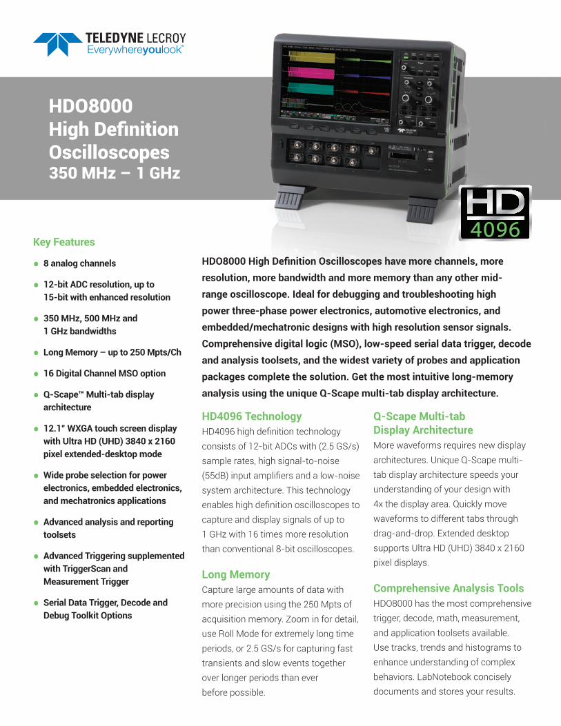
HDO8000 High Definition Oscilloscopes provide more channels, more resolution, more bandwidth and more memory. They are ideal for debugging three-phase power electronics, automotive electronics, and mechatronic systems. Mixed Signal capability allows users to simultaneously analyze 8 Analog inputs and 16 Digital inputs. Serial data Trigger, Decode, and Analysis toolsets aid in debugging embedded systems. The unique Q-Scape multi-tab display makes it easy to work with multiple channels, and the solution is completed by a wide variety of probes and application packages.
Additionally, complex embedded and mechatronic designs used in automo-tive and consumer products contain a huge number of analog, digital, power, serial data and sensor signals that makes debug challenging and time-consuming. New instrument par-adigms – more channels with higher resolutions at high bandwidths – are needed to meet these expanding and emerging needs.
Teledyne LeCroy has this new instrument – the HDO8000 Series, an 8 channel, 12-bit resolution, 1 GHz mixed-signal oscilloscope with the most comprehensive serial data, probe and application package toolsets. Use the HDO8000 to examine power elec-tronics device or three-phase output signals, high-speed microprocessor signals, or analog, digital or serial data traffic on an embedded control board. Now, you have enough to do it all.
3
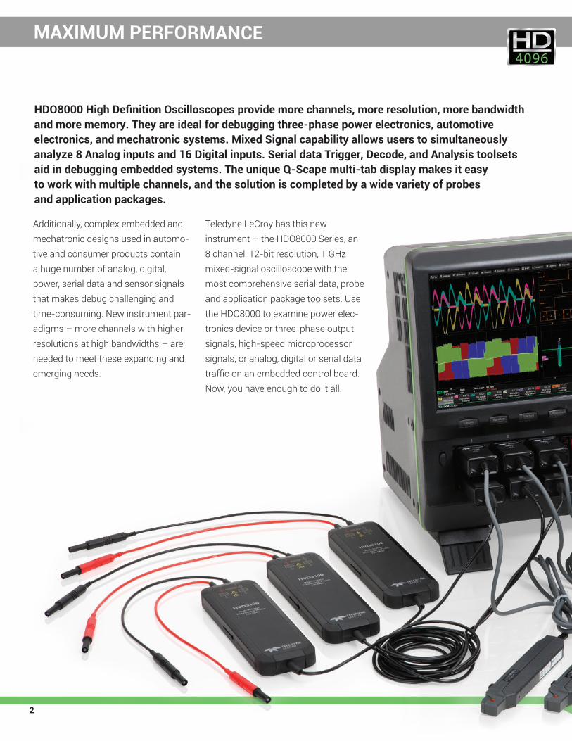
High-Power, Three-Phase Power Electronics Variable frequency motor drive de-signs are increasingly down-deployed in lower cost applications, but with increasing control complexity. Distrib-uted electric power generation
is increasing the demand for invert-ers and converters to interface these power sources to the grid, and is also driving new power electronics solu-tions to compensate, regulate and control the power flow from large amounts of distributed generation.
With the HDO8000, it is possible to monitor three-phase voltages and currents simultaneously along with the DC bus or other control and sen-sor signals. Use serial/logic triggers to isolate/correlate control or external events to establish cause and effect. 12-bit resolution provides capability for full power section characterization from device switching and conduction losses to output measurements. 1 GHz bandwidth measures the fast rise times and switching speeds of SiC and GaN devices, and also permits embedded control debug on today’s
fastest 32-bit microprocessors. 250 Mpts/ch of memory permits the most comprehensive analysis of mixed low-speed and high-speed events over long periods of time. Automotive Electronics, Hybrid/Electric Vehicle Propulsion Hybrid electric and electric vehicles (HEVs and EVs) use high-power DC-DC converters for two-way con-version of power between propulsion systems and other loads and the high voltage, 48V, and 12V distributed DC buses/batteries.
Automotive electronic control units (ECUs) are tested to some of the most stringent standards – more channels provides more insight faster. 12-bits and 250 Mpts provides the amplitude and time resolution needed for better and more intuitive cause-effect analysis.
Deep digital logic, trigger, decode and analytic toolsets provides an all-in-one characterization tool for the complex, dynamic behavior of the vehicle ECUs. Embedded, Mechatronic SystemsToday’s consumer appliances and industrial systems combine complex embedded controls, power electron-ics, and sensors to achieve the highest efficiency and provide important ben-efits. Time-to-market, cost and quality pressures place exceptional demands on new product test, debug and troubleshooting. HDO8000 capabilities provide more insight faster.
FURTHER, FINER, FASTER

4
HDO8000 High Definition Oscilloscopes provide the right capabilities for debug and troubleshooting of high power three-phase power electronics, automotive electronics, and challenging embedded or mechatronic designs.
1. 8 analog input channels
2. 12-bit HDO4096 technology - 16x closer to perfect
3. Up to 1 GHz - enough bandwidth for today and tomorrow
4. 12.1” Widescreen (16 x 9) WXGA color touch screen display - Ultra HD (UHD) (3840 x 2160) extended-desktop display.
5. Q-Scape multi-tab display architecture - 4x the display area
6. Intel® Core™ i5-4570S Quad-core 2.9 GHz (per-core) CPU with up to 32 GB of RAM
7. ProBus probe interface supports every Teledyne LeCroy probe possible
8. Supports eight simultaneous current probes
9. Mixed Signal Capability - integrated 16 channel digital logic
HDO8000 - 8 CHANNEL, 12-BIT HIGH DEFINITION
5
2
4
7
12
1
14
5Tab 1
Tab 2
Tab 3
5
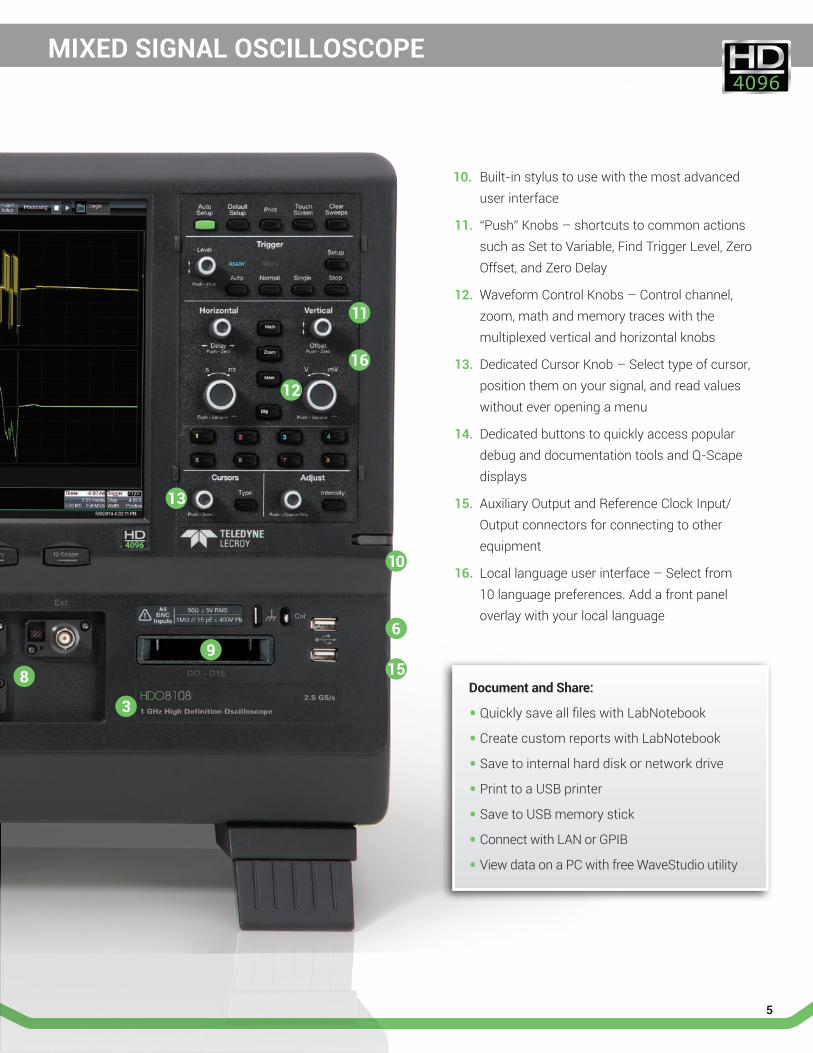
10. Built-in stylus to use with the most advanced user interface
11. “Push” Knobs – shortcuts to common actions such as Set to Variable, Find Trigger Level, Zero Offset, and Zero Delay
12. Waveform Control Knobs – Control channel, zoom, math and memory traces with the multiplexed vertical and horizontal knobs
13. Dedicated Cursor Knob – Select type of cursor, position them on your signal, and read values without ever opening a menu
14. Dedicated buttons to quickly access popular debug and documentation tools and Q-Scape displays
15. Auxiliary Output and Reference Clock Input/Output connectors for connecting to other equipment
16. Local language user interface – Select from 10 language preferences. Add a front panel overlay with your local language
Document and Share:
• Quickly save all files with LabNotebook
• Create custom reports with LabNotebook
• Save to internal hard disk or network drive
• Print to a USB printer
• Save to USB memory stick
• Connect with LAN or GPIB
• View data on a PC with free WaveStudio utility
6
3
8
10
9
11
MIXED SIGNAL OSCILLOSCOPE
12
13
15
16
6
HD4096 TECHNOLOGY - 16X CLOSER TO PERFECT
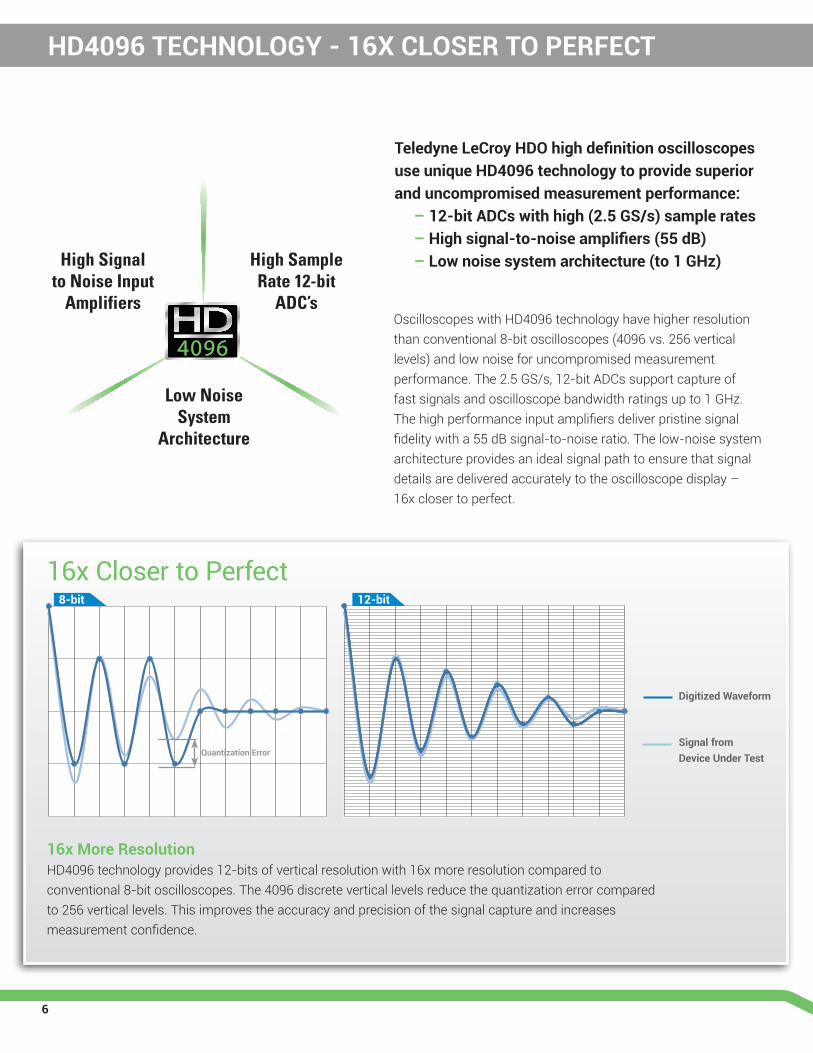
Teledyne LeCroy HDO high definition oscilloscopes use unique HD4096 technology to provide superior and uncompromised measurement performance: – 12-bit ADCs with high (2.5 GS/s) sample rates – High signal-to-noise amplifiers (55 dB) – Low noise system architecture (to 1 GHz)
Oscilloscopes with HD4096 technology have higher resolution than conventional 8-bit oscilloscopes (4096 vs. 256 vertical levels) and low noise for uncompromised measurement performance. The 2.5 GS/s, 12-bit ADCs support capture of fast signals and oscilloscope bandwidth ratings up to 1 GHz. The high performance input amplifiers deliver pristine signal fidelity with a 55 dB signal-to-noise ratio. The low-noise system architecture provides an ideal signal path to ensure that signal details are delivered accurately to the oscilloscope display – 16x closer to perfect.
High Sample Rate 12-bit
ADC’s
High Signal to Noise Input
Amplifiers
Low Noise System
Architecture
16x More ResolutionHD4096 technology provides 12-bits of vertical resolution with 16x more resolution compared to conventional 8-bit oscilloscopes. The 4096 discrete vertical levels reduce the quantization error compared to 256 vertical levels. This improves the accuracy and precision of the signal capture and increases measurement confidence.
Digitized Waveform
Signal from Device Under Test
16x Closer to Perfect 8-bit 12-bit
Quantization Error
7
EXPERIENCE THE DIFFERENCE
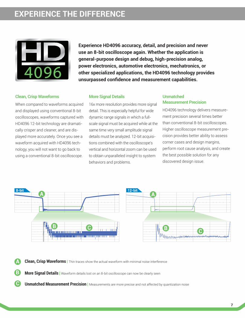
Clean, Crisp Waveforms
When compared to waveforms acquired and displayed using conventional 8-bit oscilloscopes, waveforms captured with HD4096 12-bit technology are dramati-cally crisper and cleaner, and are dis-played more accurately. Once you see a waveform acquired with HD4096 tech-nology, you will not want to go back to using a conventional 8-bit oscilloscope.
More Signal Details
16x more resolution provides more signal detail. This is especially helpful for wide dynamic range signals in which a full-scale signal must be acquired while at the same time very small amplitude signal details must be analyzed. 12-bit acquisi-tions combined with the oscilloscope’s vertical and horizontal zoom can be used to obtain unparalleled insight to system behaviors and problems.
Unmatched Measurement Precision
HD4096 technology delivers measure-ment precision several times better than conventional 8-bit oscilloscopes. Higher oscilloscope measurement pre-cision provides better ability to assess corner cases and design margins, perform root cause analysis, and create the best possible solution for any discovered design issue.
Experience HD4096 accuracy, detail, and precision and never use an 8-bit oscilloscope again. Whether the application is general-purpose design and debug, high-precision analog, power electronics, automotive electronics, mechatronics, or other specialized applications, the HD4096 technology provides unsurpassed confidence and measurement capabilities.
8-bit 12-bit
A
A A
B BC C
B
C
Clean, Crisp Waveforms | Thin traces show the actual waveform with minimal noise interference
Unmatched Measurement Precision | Measurements are more precise and not affected by quantization noise
More Signal Details | Waveform details lost on an 8-bit oscilloscope can now be clearly seen

8
High-performance 16-Channel Mixed Signal CapabilityWith embedded systems growing more complex, powerful mixed signal debug capabilities are an essential part of modern oscilloscopes. The 16 inte-grated digital channels and set of tools designed to view, measureand analyze analog and digital signals enable fast debugging of mixed signal designs.
Extensive TriggeringFlexible analog and digital cross-pattern triggering across all 20 channels provides the ability to quickly identify and isolate problems in an embedded system. Event triggering can be con-figured to arm on an analog signal and trigger on a digital pattern.
Advanced Digital Debug ToolsUsing the powerful parallel pattern search capability of WaveScan, patterns across many digital lines can be iso-lated and analyzed. Identified patterns are presented in a table with timestamp information and enables quick search-ing for each pattern occurrence. Use a variety of the many timing parameters to measure and analyze the characteristics of digital busses. Powerful tools like tracks, trends, statistics and histicons provide addi-tional insight and help find anomalies. Quickly see the state of all the digital lines at the same time using convenient activity indicators. Simulate complete digital designs using logic gate emulation. When used with the web editor, many logic gates can be combined together in one math func-tion to simulate complex logic designs. Choose from AND, OR, NAND, NOR, XOR, NOT and D Flip Flop gates.
POWERFUL MIXED SIGNAL CAPABILITIES
Teledyne LeCroy’s HDO8000 mixed signal oscilloscope option combines the high definition analog channels of the HDO8000 with the flexibility of 16 digital inputs. In addition, the many triggering and decoding options available with the mixed signal option turn the HDO8000 into an all-in-one analog, digital, and serial data debug machine.

9
SERIAL TRIGGER AND DECODE OPTIONS
Trigger and DecodeThe serial data trigger will quickly iso-late events on a bus eliminating the need to set manual triggers and hoping to catch the right information. Trigger conditions can be entered in binary or hexadecimal formats and conditional trigger capabilities even allow trigger-ing on a range of different events. Protocol decoding is shown directly on the waveform with an intuitive, color-coded overlay and presented in binary, hex or ASCII. Decoding on the HDO8000 is fast even with long mem-ory and zooming in to the waveform shows precise byte by byte decoding.
Table and SearchTo further simplify the debug process all decoded data can be displayed in a table below the waveform grid. Select-ing an entry in the table with the touch screen will display just that event. Additionally, built-in search functional-ity will find specific decoded values. Serial data messages can be quickly located by searching on address, data and other attributes specific to a particular protocol. Once found, the specific location containing the specified search criteria can be auto-matically zoomed to.
View decoded protocol information on top of physical layer waveforms and trigger on protocol specific messages.
PROTObus MAG Serial Debug ToolkitPROTObus MAG Serial Data Debug Toolkit extends the trigger and decode functions of serial data through integration of measure-ment parameters with waveform math. Nine additional measurements quickly sets up and displays encoded data as an analog waveform. Define specific data frame filters and data field triggers to confirm performance of embedded nodes.
Supported Serial Data Protocols
• I2C, SPI, UART
• CAN, LIN, FlexRay™, SENT
• Ethernet 10/100BaseT, USB 1.0/1.1/2.0, USB 2.0-HSIC
• Audio (I2S, LJ, RJ, TDM)
• MIL-STD-1553, ARINC 429
• MIPI D-PHY, DigRF 3G, DigRFv4
• Manchester, NRZ
Debugging serial data busses can be confusing and time consuming. The serial data and decode options for HDO8000 provide time saving tools for serial bus debug and validation.
10
IDENTIFY AND ISOLATE PROBLEMS FASTER
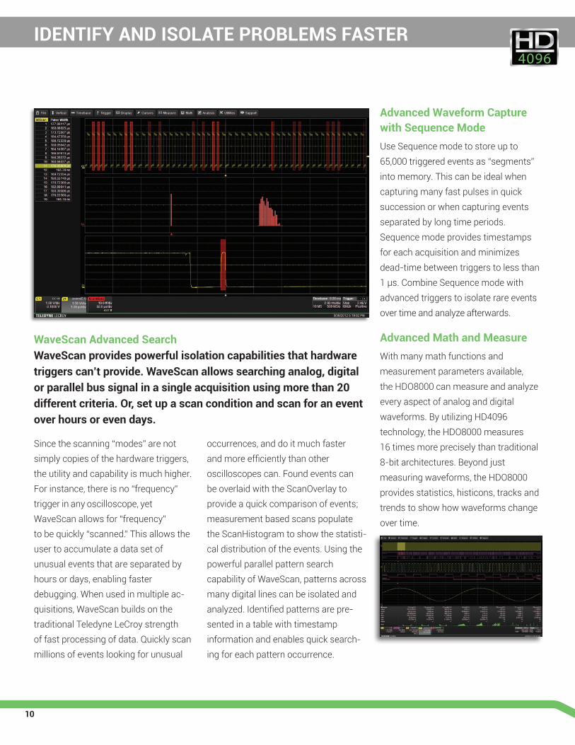
WaveScan Advanced SearchWaveScan provides powerful isolation capabilities that hardware triggers can’t provide. WaveScan allows searching analog, digital or parallel bus signal in a single acquisition using more than 20 different criteria. Or, set up a scan condition and scan for an event over hours or even days.
Since the scanning “modes” are not simply copies of the hardware trig gers, the utility and capa bility is much higher. For instance, there is no “frequency” trigger in any oscilloscope, yet WaveScan allows for “frequency” to be quickly “scanned.” This allows the user to accumulate a data set of unusual events that are separated by hours or days, enabling faster debugging. When used in multiple ac-quisitions, WaveScan builds on the traditional Teledyne LeCroy strength of fast processing of data. Quickly scan millions of events looking for unusual
occurrences, and do it much faster and more efficiently than other oscilloscopes can. Found events can be overlaid with the ScanOverlay to provide a quick comparison of events; measurement based scans populate the ScanHistogram to show the statisti-cal distribution of the events. Using the powerful parallel pattern search capability of WaveScan, patterns across many digital lines can be isolated and analyzed. Identified patterns are pre-sented in a table with timestamp information and enables quick search-ing for each pattern occurrence.
Advanced Waveform Capture with Sequence ModeUse Sequence mode to store up to 65,000 triggered events as “segments” into memory. This can be ideal when capturing many fast pulses in quick succession or when capturing events separated by long time periods. Sequence mode provides timestamps for each acquisition and minimizes dead-time between triggers to less than 1 μ s. Combine Sequence mode with advanced triggers to isolate rare events over time and analyze afterwards.
Advanced Math and MeasureWith many math functions and measurement parameters available, the HDO8000 can measure and analyze every aspect of analog and digital waveforms. By utilizing HD4096 technology, the HDO8000 measures 16 times more precisely than traditional 8-bit architectures. Beyond just measuring waveforms, the HDO8000 provides statistics, histicons, tracks and trends to show how waveforms change over time.
11
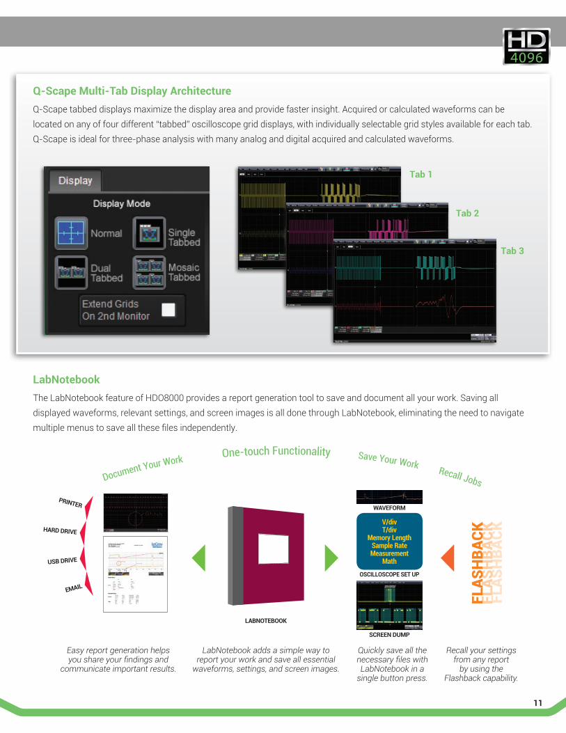
Q-Scape Multi-Tab Display ArchitectureQ-Scape tabbed displays maximize the display area and provide faster insight. Acquired or calculated waveforms can be located on any of four different “tabbed” oscilloscope grid displays, with individually selectable grid styles available for each tab. Q-Scape is ideal for three-phase analysis with many analog and digital acquired and calculated waveforms.
LabNotebookThe LabNotebook feature of HDO8000 provides a report generation tool to save and document all your work. Saving all displayed waveforms, relevant settings, and screen images is all done through LabNotebook, eliminating the need to navigate multiple menus to save all these files independently.
V/divT/div
Memory LengthSample RateMeasurement
Math
WAVEFORM
OSCILLOSCOPE SET UP
SCREEN DUMP
PRINTER
HARD DRIVE
USB DRIVE
Document Your Work One-touch Functionality Save Your Work Recall Jobs
Easy report generation helps you share your findings and
communicate important results.
LabNotebook adds a simple way to report your work and save all essential
waveforms, settings, and screen images.
Quickly save all the necessary files with LabNotebook in a
single button press.
Recall your settings from any report
by using the Flashback capability.
FLAS
HBA
CKFL
ASH
BACK
FLAS
HBA
CK
LABNOTEBOOK
Tab 1
Tab 2
Tab 3
12
SPECTRUM ANALYZER MODE
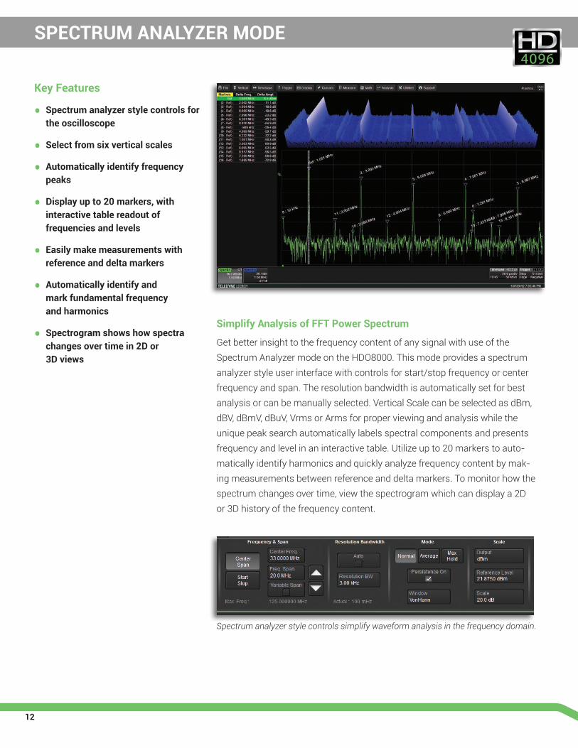
Simplify Analysis of FFT Power Spectrum
Get better insight to the frequency content of any signal with use of the Spectrum Analyzer mode on the HDO8000. This mode provides a spectrum analyzer style user interface with controls for start/stop frequency or center frequency and span. The resolution bandwidth is automatically set for best analysis or can be manually selected. Vertical Scale can be selected as dBm, dBV, dBmV, dBuV, Vrms or Arms for proper viewing and analysis while the unique peak search automatically labels spectral components and presents frequency and level in an interactive table. Utilize up to 20 markers to auto-matically identify harmonics and quickly analyze frequency content by mak-ing measurements between reference and delta markers. To monitor how the spectrum changes over time, view the spectrogram which can display a 2D or 3D history of the frequency content.
Spectrum analyzer style controls simplify waveform analysis in the frequency domain.
Key Features
• Spectrum analyzer style controls for the oscilloscope
• Select from six vertical scales
• Automatically identify frequency peaks
• Display up to 20 markers, with interactive table readout of frequencies and levels
• Easily make measurements with reference and delta markers
• Automatically identify and mark fundamental frequency and harmonics
• Spectrogram shows how spectra changes over time in 2D or 3D views
13
DEVICE AND SWITCHING POWER SUPPLY ANALYSIS
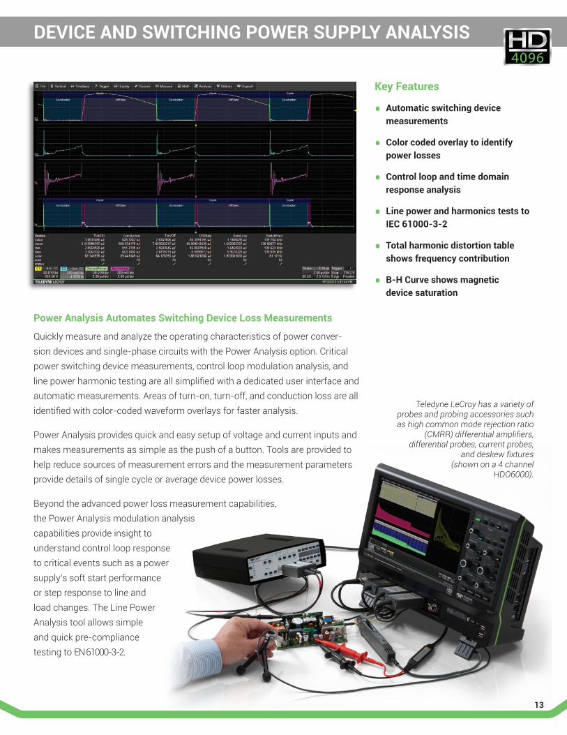
Power Analysis Automates Switching Device Loss Measurements
Quickly measure and analyze the operating characteristics of power conver-sion devices and single-phase circuits with the Power Analysis option. Critical power switching device measurements, control loop modulation analysis, and line power harmonic testing are all simplified with a dedicated user interface and automatic measurements. Areas of turn-on, turn-off, and conduction loss are all identified with color-coded waveform overlays for faster analysis. Power Analysis provides quick and easy setup of voltage and current inputs and makes measurements as simple as the push of a button. Tools are provided to help reduce sources of measurement errors and the measurement parameters provide details of single cycle or average device power losses. Beyond the advanced power loss measurement capabilities, the Power Analysis modulation analysis capabilities provide insight to understand control loop response to critical events such as a power supply’s soft start performance or step response to line and load changes. The Line Power Analysis tool allows simple and quick pre-compliance testing to EN 61000-3-2.
Teledyne LeCroy has a variety of probes and probing accessories such as high common mode rejection ratio
(CMRR) differential amplifiers, differential probes, current probes,
and deskew fixtures (shown on a 4 channel
HDO6000).
Key Features
• Automatic switching device measurements
• Color coded overlay to identify power losses
• Control loop and time domain response analysis
• Line power and harmonics tests to IEC 61000-3-2
• Total harmonic distortion table shows frequency contribution
• B-H Curve shows magnetic device saturation
14
PROBES
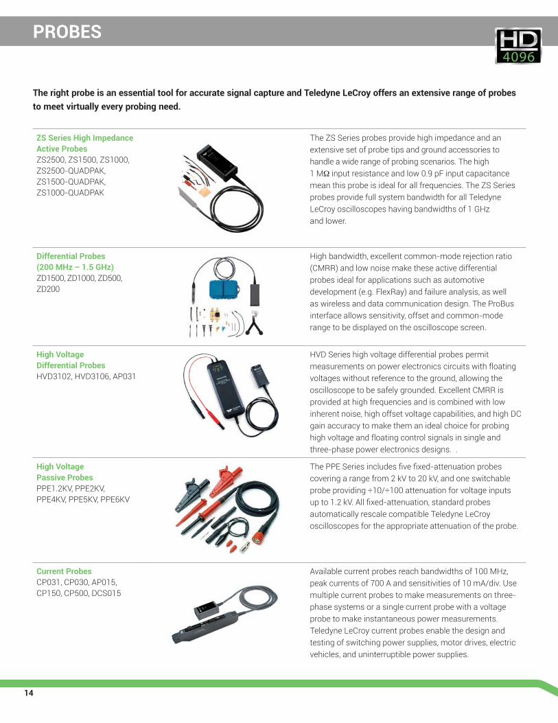
ZS Series High Impedance Active Probes ZS2500, ZS1500, ZS1000, ZS2500-QUADPAK, ZS1500-QUADPAK, ZS1000-QUADPAK
The ZS Series probes provide high impedance and an extensive set of probe tips and ground accessories to handle a wide range of probing scenarios. The high 1 MΩ input resistance and low 0.9 pF input capacitance mean this probe is ideal for all frequencies. The ZS Series probes provide full system bandwidth for all Teledyne LeCroy oscilloscopes having bandwidths of 1 GHz and lower.
Differential Probes (200 MHz – 1.5 GHz)ZD1500, ZD1000, ZD500, ZD200
High bandwidth, excellent common-mode rejection ratio (CMRR) and low noise make these active differential probes ideal for applications such as automotive development (e.g. FlexRay) and failure analysis, as well as wireless and data communication design. The ProBus interface allows sensitivity, offset and common-mode range to be displayed on the oscilloscope screen.
High Voltage Differential ProbesHVD3102, HVD3106, AP031
HVD Series high voltage differential probes permit measurements on power electronics circuits with floating voltages without reference to the ground, allowing the oscilloscope to be safely grounded. Excellent CMRR is provided at high frequencies and is combined with low inherent noise, high offset voltage capabilities, and high DC gain accuracy to make them an ideal choice for probing high voltage and floating control signals in single and three-phase power electronics designs. .
High Voltage Passive ProbesPPE1.2KV, PPE2KV, PPE4KV, PPE5KV, PPE6KV
The PPE Series includes five fixed-attenuation probes covering a range from 2 kV to 20 kV, and one switchable probe providing ÷10/÷100 attenuation for voltage inputs up to 1.2 kV. All fixed-attenuation, standard probes automatically rescale compatible Teledyne LeCroy oscilloscopes for the appropriate attenuation of the probe.
Current ProbesCP031, CP030, AP015, CP150, CP500, DCS015
Available current probes reach bandwidths of 100 MHz, peak currents of 700 A and sensitivities of 10 mA/div. Use multiple current probes to make measurements on three-phase systems or a single current probe with a voltage probe to make instantaneous power measurements. Teledyne LeCroy current probes enable the design and testing of switching power supplies, motor drives, electric vehicles, and uninterruptible power supplies.
The right probe is an essential tool for accurate signal capture and Teledyne LeCroy offers an extensive range of probes to meet virtually every probing need.
15
SPECIFICATIONS
HDO8038 HDO8058 HDO8108
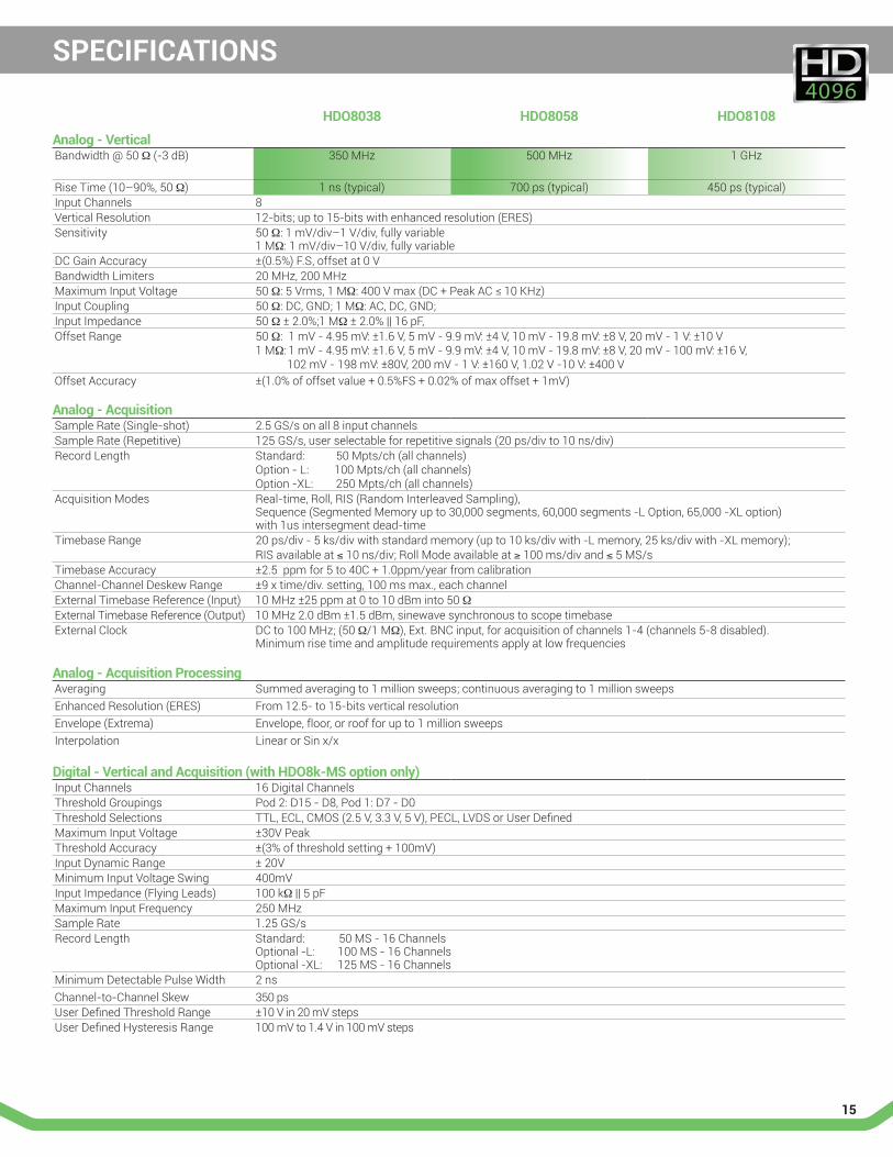
Analog - VerticalBandwidth @ 50 Ω (-3 dB) 350 MHz 500 MHz 1 GHz
Rise Time (10–90%, 50 Ω) 1 ns (typical) 700 ps (typical) 450 ps (typical)Input Channels 8Vertical Resolution 12-bits; up to 15-bits with enhanced resolution (ERES)Sensitivity 50 Ω: 1 mV/div–1 V/div, fully variable
1 MΩ: 1 mV/div–10 V/div, fully variableDC Gain Accuracy ±(0.5%) F.S, offset at 0 VBandwidth Limiters 20 MHz, 200 MHzMaximum Input Voltage 50 Ω: 5 Vrms, 1 MΩ: 400 V max (DC + Peak AC ≤ 10 KHz)Input Coupling 50 Ω: DC, GND; 1 MΩ: AC, DC, GND;Input Impedance 50 Ω ± 2.0%;1 MΩ ± 2.0% || 16 pF,Offset Range 50 Ω: 1 mV - 4.95 mV: ±1.6 V, 5 mV - 9.9 mV: ±4 V, 10 mV - 19.8 mV: ±8 V, 20 mV - 1 V: ±10 V
1 MΩ: 1 mV - 4.95 mV: ±1.6 V, 5 mV - 9.9 mV: ±4 V, 10 mV - 19.8 mV: ±8 V, 20 mV - 100 mV: ±16 V, 102 mV - 198 mV: ±80V, 200 mV - 1 V: ±160 V, 1.02 V -10 V: ±400 V
Offset Accuracy ±(1.0% of offset value + 0.5%FS + 0.02% of max offset + 1mV)
Analog - AcquisitionSample Rate (Single-shot) 2.5 GS/s on all 8 input channelsSample Rate (Repetitive) 125 GS/s, user selectable for repetitive signals (20 ps/div to 10 ns/div)Record Length Standard: 50 Mpts/ch (all channels)
Option - L: 100 Mpts/ch (all channels)Option -XL: 250 Mpts/ch (all channels)
Acquisition Modes Real-time, Roll, RIS (Random Interleaved Sampling), Sequence (Segmented Memory up to 30,000 segments, 60,000 segments -L Option, 65,000 -XL option) with 1us intersegment dead-time
Timebase Range 20 ps/div - 5 ks/div with standard memory (up to 10 ks/div with -L memory, 25 ks/div with -XL memory);RIS available at ≤ 10 ns/div; Roll Mode available at ≥ 100 ms/div and ≤ 5 MS/s
Timebase Accuracy ±2.5 ppm for 5 to 40C + 1.0ppm/year from calibrationChannel-Channel Deskew Range ±9 x time/div. setting, 100 ms max., each channelExternal Timebase Reference (Input) 10 MHz ±25 ppm at 0 to 10 dBm into 50 ΩExternal Timebase Reference (Output) 10 MHz 2.0 dBm ±1.5 dBm, sinewave synchronous to scope timebaseExternal Clock DC to 100 MHz; (50 Ω/1 MΩ), Ext. BNC input, for acquisition of channels 1-4 (channels 5-8 disabled).
Minimum rise time and amplitude requirements apply at low frequencies
Analog - Acquisition ProcessingAveraging Summed averaging to 1 million sweeps; continuous averaging to 1 million sweepsEnhanced Resolution (ERES) From 12.5- to 15-bits vertical resolutionEnvelope (Extrema) Envelope, floor, or roof for up to 1 million sweepsInterpolation Linear or Sin x/x
Digital - Vertical and Acquisition (with HDO8k-MS option only)Input Channels 16 Digital ChannelsThreshold Groupings Pod 2: D15 - D8, Pod 1: D7 - D0Threshold Selections TTL, ECL, CMOS (2.5 V, 3.3 V, 5 V), PECL, LVDS or User DefinedMaximum Input Voltage ±30V PeakThreshold Accuracy ±(3% of threshold setting + 100mV)Input Dynamic Range ± 20VMinimum Input Voltage Swing 400mVInput Impedance (Flying Leads) 100 kΩ || 5 pFMaximum Input Frequency 250 MHzSample Rate 1.25 GS/sRecord Length Standard: 50 MS - 16 Channels
Optional -L: 100 MS - 16 Channels Optional -XL: 125 MS - 16 Channels
Minimum Detectable Pulse Width 2 nsChannel-to-Channel Skew 350 psUser Defined Threshold Range ±10 V in 20 mV stepsUser Defined Hysteresis Range 100 mV to 1.4 V in 100 mV steps
16
SPECIFICATIONS
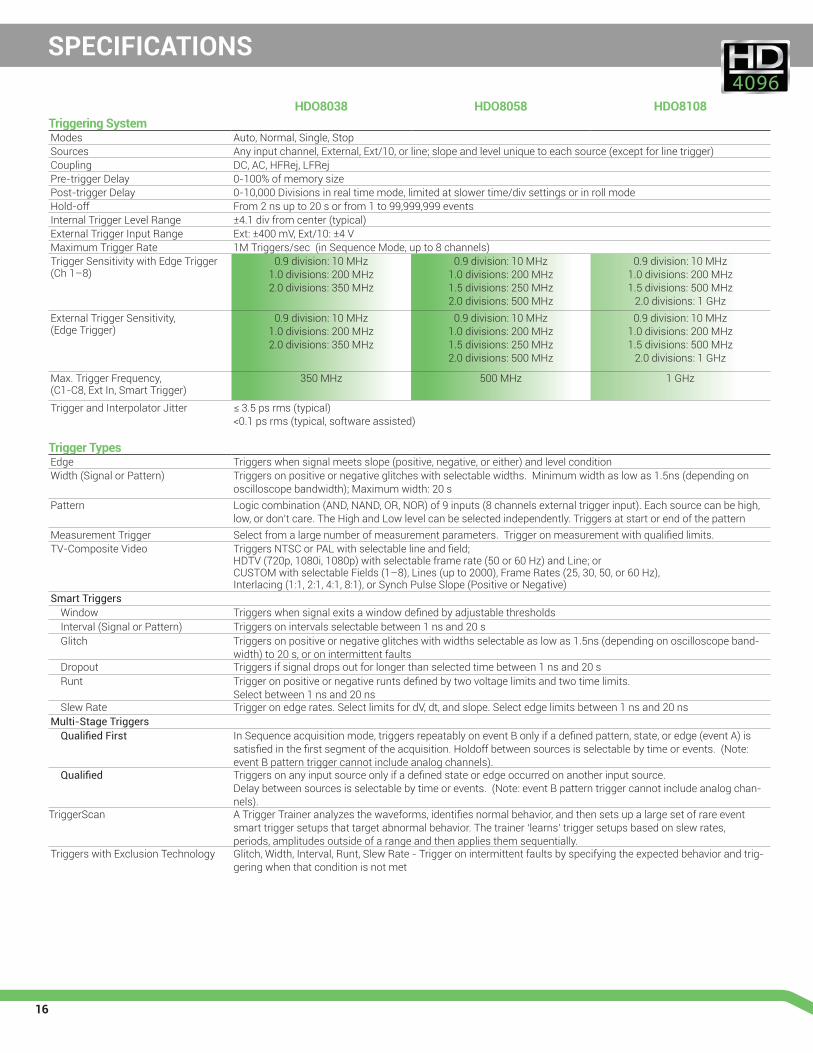
HDO8038 HDO8058 HDO8108Triggering SystemModes Auto, Normal, Single, StopSources Any input channel, External, Ext/10, or line; slope and level unique to each source (except for line trigger)Coupling DC, AC, HFRej, LFRejPre-trigger Delay 0-100% of memory sizePost-trigger Delay 0-10,000 Divisions in real time mode, limited at slower time/div settings or in roll modeHold-off From 2 ns up to 20 s or from 1 to 99,999,999 eventsInternal Trigger Level Range ±4.1 div from center (typical)External Trigger Input Range Ext: ±400 mV, Ext/10: ±4 VMaximum Trigger Rate 1M Triggers/sec (in Sequence Mode, up to 8 channels) Trigger Sensitivity with Edge Trigger (Ch 1–8)
0.9 division: 10 MHz1.0 divisions: 200 MHz2.0 divisions: 350 MHz
0.9 division: 10 MHz1.0 divisions: 200 MHz1.5 divisions: 250 MHz2.0 divisions: 500 MHz
0.9 division: 10 MHz1.0 divisions: 200 MHz1.5 divisions: 500 MHz
2.0 divisions: 1 GHzExternal Trigger Sensitivity, (Edge Trigger)
0.9 division: 10 MHz1.0 divisions: 200 MHz2.0 divisions: 350 MHz
0.9 division: 10 MHz1.0 divisions: 200 MHz1.5 divisions: 250 MHz2.0 divisions: 500 MHz
0.9 division: 10 MHz1.0 divisions: 200 MHz1.5 divisions: 500 MHz
2.0 divisions: 1 GHz
Max. Trigger Frequency, (C1-C8, Ext In, Smart Trigger)
350 MHz 500 MHz 1 GHz
Trigger and Interpolator Jitter ≤ 3.5 ps rms (typical)<0.1 ps rms (typical, software assisted)
Trigger TypesEdge Triggers when signal meets slope (positive, negative, or either) and level conditionWidth (Signal or Pattern) Triggers on positive or negative glitches with selectable widths. Minimum width as low as 1.5ns (depending on
oscilloscope bandwidth); Maximum width: 20 sPattern Logic combination (AND, NAND, OR, NOR) of 9 inputs (8 channels external trigger input). Each source can be high,
low, or don’t care. The High and Low level can be selected independently. Triggers at start or end of the patternMeasurement Trigger Select from a large number of measurement parameters. Trigger on measurement with qualified limits.TV-Composite Video Triggers NTSC or PAL with selectable line and field;
HDTV (720p, 1080i, 1080p) with selectable frame rate (50 or 60 Hz) and Line; or CUSTOM with selectable Fields (1–8), Lines (up to 2000), Frame Rates (25, 30, 50, or 60 Hz), Interlacing (1:1, 2:1, 4:1, 8:1), or Synch Pulse Slope (Positive or Negative)
Smart TriggersWindow Triggers when signal exits a window defined by adjustable thresholdsInterval (Signal or Pattern) Triggers on intervals selectable between 1 ns and 20 sGlitch Triggers on positive or negative glitches with widths selectable as low as 1.5ns (depending on oscilloscope band-
width) to 20 s, or on intermittent faultsDropout Triggers if signal drops out for longer than selected time between 1 ns and 20 sRunt Trigger on positive or negative runts defined by two voltage limits and two time limits.
Select between 1 ns and 20 nsSlew Rate Trigger on edge rates. Select limits for dV, dt, and slope. Select edge limits between 1 ns and 20 ns
Multi-Stage TriggersQualified First In Sequence acquisition mode, triggers repeatably on event B only if a defined pattern, state, or edge (event A) is
satisfied in the first segment of the acquisition. Holdoff between sources is selectable by time or events. (Note: event B pattern trigger cannot include analog channels).
Qualified Triggers on any input source only if a defined state or edge occurred on another input source. Delay between sources is selectable by time or events. (Note: event B pattern trigger cannot include analog chan-nels).
TriggerScan A Trigger Trainer analyzes the waveforms, identifies normal behavior, and then sets up a large set of rare event smart trigger setups that target abnormal behavior. The trainer ‘learns’ trigger setups based on slew rates, periods, amplitudes outside of a range and then applies them sequentially.
Triggers with Exclusion Technology Glitch, Width, Interval, Runt, Slew Rate - Trigger on intermittent faults by specifying the expected behavior and trig-gering when that condition is not met
17
SPECIFICATIONS
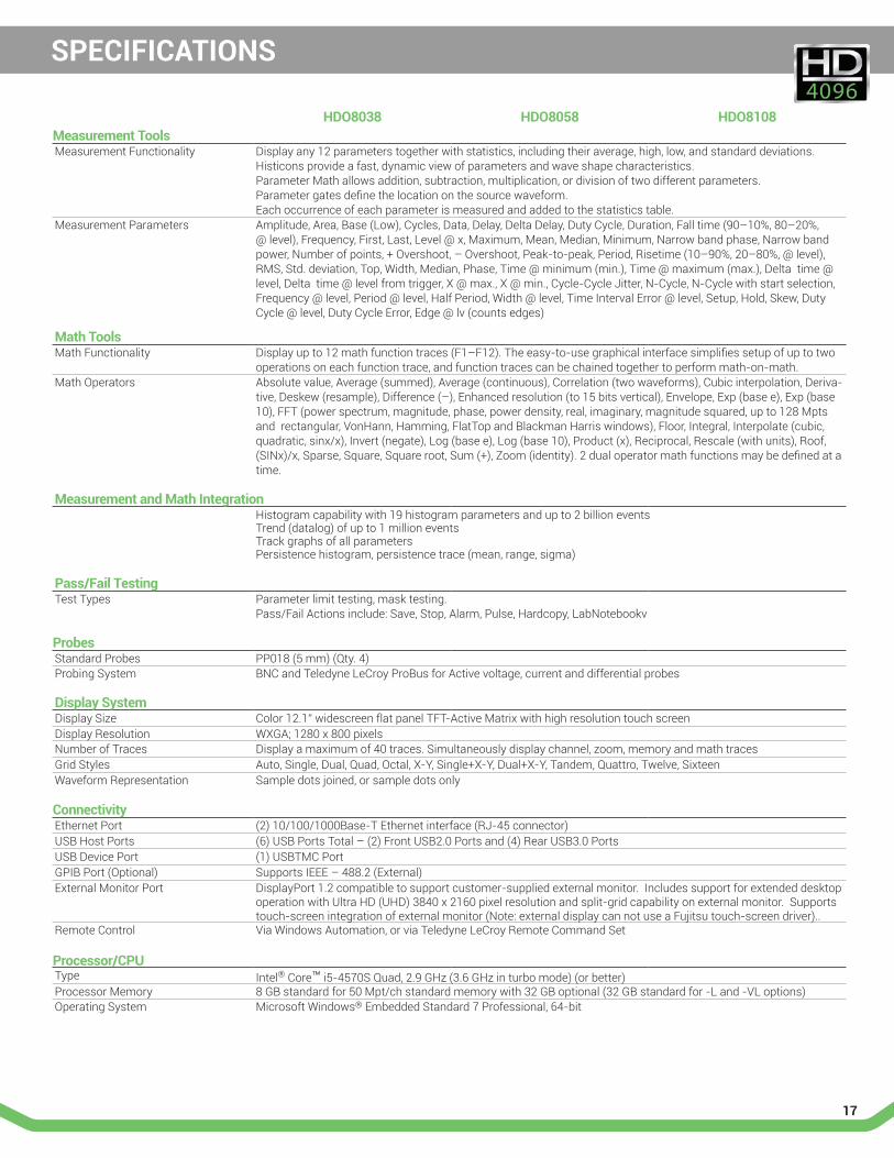
HDO8038 HDO8058 HDO8108Measurement ToolsMeasurement Functionality Display any 12 parameters together with statistics, including their average, high, low, and standard deviations.
Histicons provide a fast, dynamic view of parameters and wave shape characteristics. Parameter Math allows addition, subtraction, multiplication, or division of two different parameters. Parameter gates define the location on the source waveform. Each occurrence of each parameter is measured and added to the statistics table.
Measurement Parameters Amplitude, Area, Base (Low), Cycles, Data, Delay, Delta Delay, Duty Cycle, Duration, Fall time (90–10%, 80–20%, @ level), Frequency, First, Last, Level @ x, Maximum, Mean, Median, Minimum, Narrow band phase, Narrow band power, Number of points, + Overshoot, – Overshoot, Peak-to-peak, Period, Risetime (10–90%, 20–80%, @ level), RMS, Std. deviation, Top, Width, Median, Phase, Time @ minimum (min.), Time @ maximum (max.), Delta time @ level, Delta time @ level from trigger, X @ max., X @ min., Cycle-Cycle Jitter, N-Cycle, N-Cycle with start selection, Frequency @ level, Period @ level, Half Period, Width @ level, Time Interval Error @ level, Setup, Hold, Skew, Duty Cycle @ level, Duty Cycle Error, Edge @ lv (counts edges)
Math ToolsMath Functionality Display up to 12 math function traces (F1–F12). The easy-to-use graphical interface simplifies setup of up to two
operations on each function trace, and function traces can be chained together to perform math-on-math.Math Operators Absolute value, Average (summed), Average (continuous), Correlation (two waveforms), Cubic interpolation, Deriva-
tive, Deskew (resample), Difference (–), Enhanced resolution (to 15 bits vertical), Envelope, Exp (base e), Exp (base 10), FFT (power spectrum, magnitude, phase, power density, real, imaginary, magnitude squared, up to 128 Mpts and rectangular, VonHann, Hamming, FlatTop and Blackman Harris windows), Floor, Integral, Interpolate (cubic, quadratic, sinx/x), Invert (negate), Log (base e), Log (base 10), Product (x), Reciprocal, Rescale (with units), Roof, (SINx)/x, Sparse, Square, Square root, Sum (+), Zoom (identity). 2 dual operator math functions may be defined at a time.
Measurement and Math IntegrationHistogram capability with 19 histogram parameters and up to 2 billion events Trend (datalog) of up to 1 million events Track graphs of all parameters Persistence histogram, persistence trace (mean, range, sigma)
Pass/Fail TestingTest Types Parameter limit testing, mask testing.
Pass/Fail Actions include: Save, Stop, Alarm, Pulse, Hardcopy, LabNotebookv
ProbesStandard Probes PP018 (5 mm) (Qty. 4)Probing System BNC and Teledyne LeCroy ProBus for Active voltage, current and differential probes
Display SystemDisplay Size Color 12.1” widescreen flat panel TFT-Active Matrix with high resolution touch screenDisplay Resolution WXGA; 1280 x 800 pixelsNumber of Traces Display a maximum of 40 traces. Simultaneously display channel, zoom, memory and math tracesGrid Styles Auto, Single, Dual, Quad, Octal, X-Y, Single+X-Y, Dual+X-Y, Tandem, Quattro, Twelve, SixteenWaveform Representation Sample dots joined, or sample dots only
ConnectivityEthernet Port (2) 10/100/1000Base-T Ethernet interface (RJ-45 connector)USB Host Ports (6) USB Ports Total – (2) Front USB2.0 Ports and (4) Rear USB3.0 PortsUSB Device Port (1) USBTMC PortGPIB Port (Optional) Supports IEEE – 488.2 (External)External Monitor Port DisplayPort 1.2 compatible to support customer-supplied external monitor. Includes support for extended desktop
operation with Ultra HD (UHD) 3840 x 2160 pixel resolution and split-grid capability on external monitor. Supports touch-screen integration of external monitor (Note: external display can not use a Fujitsu touch-screen driver)..
Remote Control Via Windows Automation, or via Teledyne LeCroy Remote Command Set
Processor/CPUType Intel® Core™ i5-4570S Quad, 2.9 GHz (3.6 GHz in turbo mode) (or better)Processor Memory 8 GB standard for 50 Mpt/ch standard memory with 32 GB optional (32 GB standard for -L and -VL options)Operating System Microsoft Windows® Embedded Standard 7 Professional, 64-bit
18
SPECIFICATIONS
HDO8038 HDO8058 HDO8108
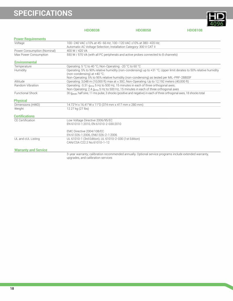
Power RequirementsVoltage 100–240 VAC ±10% at 45–66 Hz; 100–120 VAC ±10% at 380–420 Hz;
Automatic AC Voltage Selection; Installation Category: 300 V CAT IIPower Consumption (Nominal) 400 W / 420 VAMax Power Consumption 550 W / 570 VA (with all PC peripherals and active probes connected to 8 channels)
EnvironmentalTemperature Operating: 5 °C to 40 °C; Non-Operating: -20 °C to 60 °CHumidity Operating: 5% to 90% relative humidity (non-condensing) up to +31 °C, Upper limit derates to 50% relative humidity
(non-condensing) at +40 °C; Non-Operating: 5% to 95% relative humidity (non-condensing) as tested per MIL-PRF-28800F
Altitude Operating: 3,048 m (10,000 ft) max at ≤ 30C; Non-Operating: Up to 12,192 meters (40,000 ft)Random Vibration Operating : 0.31 grms 5 Hz to 500 Hz, 15 minutes in each of three orthogonal axes;
Non-Operating: 2.4 grms 5 Hz to 500 Hz, 15 minutes in each of three orthogonal axesFunctional Shock 30 gpeak, half sine, 11 ms pulse, 3 shocks (positive and negative) in each of three orthogonal axes, 18 shocks total
PhysicalDimensions (HWD) 14.72”H x 16.41”W x 11”D (374 mm x 417 mm x 280 mm)Weight 12.27 kg (27 lbs)
CertificationsCE Certification Low Voltage Directive 2006/95/EC
EN 61010-1:2010, EN 61010-2-030:2010 EMC Directive 2004/108/EC EN 61326-1:2006, EN61326-2-1:2006
UL and cUL Listing UL 61010-1 (3rd Edition), UL 61010-2-030 (1st Edition) CAN/CSA C22.2 No.61010-1-12
Warranty and Service3-year warranty; calibration recommended annually. Optional service programs include extended warranty,upgrades, and calibration services
19
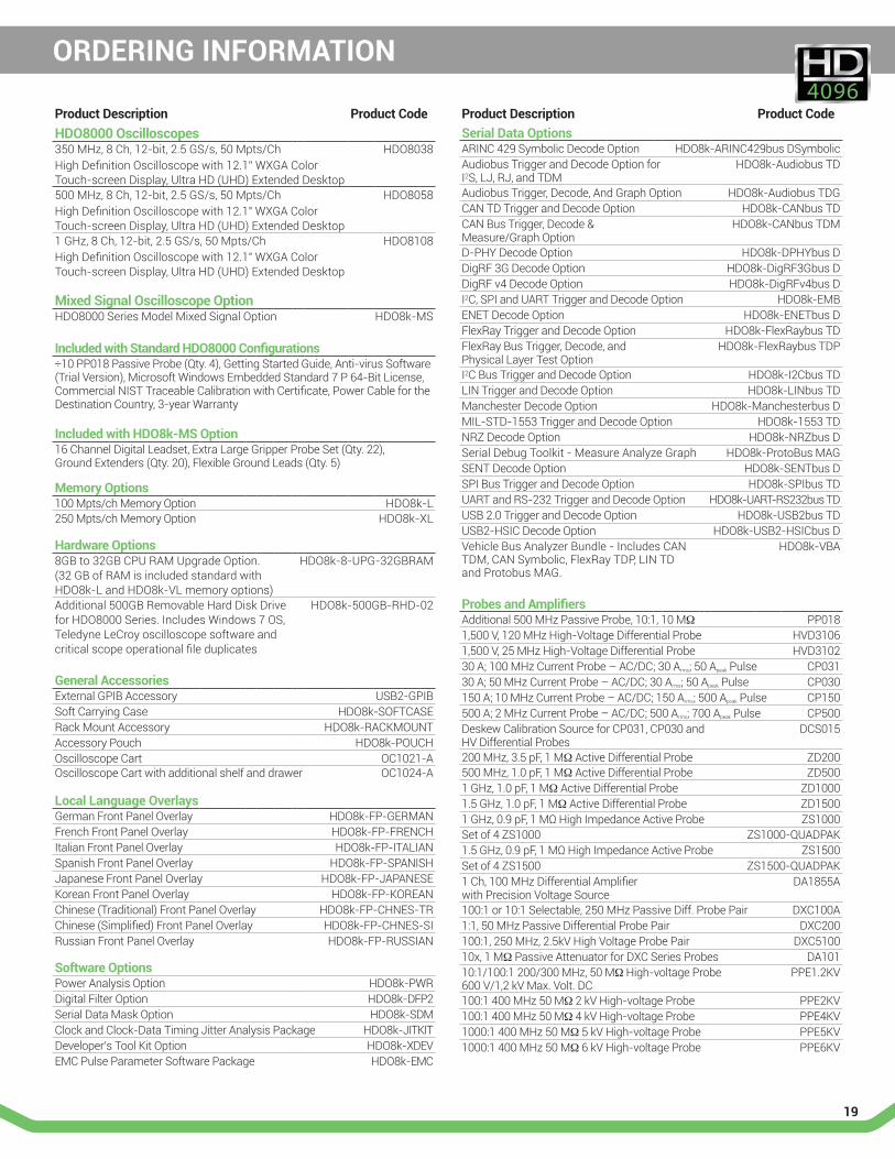
Product Description Product CodeHDO8000 Oscilloscopes350 MHz, 8 Ch, 12-bit, 2.5 GS/s, 50 Mpts/Ch High Definition Oscilloscope with 12.1” WXGA Color Touch-screen Display, Ultra HD (UHD) Extended Desktop
HDO8038
500 MHz, 8 Ch, 12-bit, 2.5 GS/s, 50 Mpts/Ch High Definition Oscilloscope with 12.1" WXGA Color Touch-screen Display, Ultra HD (UHD) Extended Desktop
HDO8058
1 GHz, 8 Ch, 12-bit, 2.5 GS/s, 50 Mpts/Ch High Definition Oscilloscope with 12.1" WXGA Color Touch-screen Display, Ultra HD (UHD) Extended Desktop
HDO8108
Mixed Signal Oscilloscope OptionHDO8000 Series Model Mixed Signal Option HDO8k-MS
Included with Standard HDO8000 Configurations÷10 PP018 Passive Probe (Qty. 4), Getting Started Guide, Anti-virus Software (Trial Version), Microsoft Windows Embedded Standard 7 P 64-Bit License, Commercial NIST Traceable Calibration with Certificate, Power Cable for the Destination Country, 3-year Warranty
Included with HDO8k-MS Option16 Channel Digital Leadset, Extra Large Gripper Probe Set (Qty. 22), Ground Extenders (Qty. 20), Flexible Ground Leads (Qty. 5)
Memory Options100 Mpts/ch Memory Option HDO8k-L250 Mpts/ch Memory Option HDO8k-XL
Hardware Options8GB to 32GB CPU RAM Upgrade Option. (32 GB of RAM is included standard with HDO8k-L and HDO8k-VL memory options)
HDO8k-8-UPG-32GBRAM
Additional 500GB Removable Hard Disk Drive for HDO8000 Series. Includes Windows 7 OS, Teledyne LeCroy oscilloscope software and critical scope operational file duplicates
HDO8k-500GB-RHD-02
General AccessoriesExternal GPIB Accessory USB2-GPIBSoft Carrying Case HDO8k-SOFTCASERack Mount Accessory HDO8k-RACKMOUNTAccessory Pouch HDO8k-POUCHOscilloscope Cart OC1021-AOscilloscope Cart with additional shelf and drawer OC1024-A
Local Language OverlaysGerman Front Panel Overlay HDO8k-FP-GERMANFrench Front Panel Overlay HDO8k-FP-FRENCHItalian Front Panel Overlay HDO8k-FP-ITALIANSpanish Front Panel Overlay HDO8k-FP-SPANISHJapanese Front Panel Overlay HDO8k-FP-JAPANESEKorean Front Panel Overlay HDO8k-FP-KOREANChinese (Traditional) Front Panel Overlay HDO8k-FP-CHNES-TRChinese (Simplified) Front Panel Overlay HDO8k-FP-CHNES-SIRussian Front Panel Overlay HDO8k-FP-RUSSIAN
Software OptionsPower Analysis Option HDO8k-PWRDigital Filter Option HDO8k-DFP2Serial Data Mask Option HDO8k-SDMClock and Clock-Data Timing Jitter Analysis Package HDO8k-JITKITDeveloper’s Tool Kit Option HDO8k-XDEVEMC Pulse Parameter Software Package HDO8k-EMC
ORDERING INFORMATION
Product Description Product CodeSerial Data OptionsARINC 429 Symbolic Decode Option HDO8k-ARINC429bus DSymbolicAudiobus Trigger and Decode Option for I2S, LJ, RJ, and TDM
HDO8k-Audiobus TD
Audiobus Trigger, Decode, And Graph Option HDO8k-Audiobus TDGCAN TD Trigger and Decode Option HDO8k-CANbus TDCAN Bus Trigger, Decode & Measure/Graph Option
HDO8k-CANbus TDM
D-PHY Decode Option HDO8k-DPHYbus DDigRF 3G Decode Option HDO8k-DigRF3Gbus DDigRF v4 Decode Option HDO8k-DigRFv4bus DI2C, SPI and UART Trigger and Decode Option HDO8k-EMBENET Decode Option HDO8k-ENETbus DFlexRay Trigger and Decode Option HDO8k-FlexRaybus TDFlexRay Bus Trigger, Decode, and Physical Layer Test Option
HDO8k-FlexRaybus TDP
I2C Bus Trigger and Decode Option HDO8k-I2Cbus TDLIN Trigger and Decode Option HDO8k-LINbus TDManchester Decode Option HDO8k-Manchesterbus DMIL-STD-1553 Trigger and Decode Option HDO8k-1553 TDNRZ Decode Option HDO8k-NRZbus DSerial Debug Toolkit - Measure Analyze Graph HDO8k-ProtoBus MAGSENT Decode Option HDO8k-SENTbus DSPI Bus Trigger and Decode Option HDO8k-SPIbus TDUART and RS-232 Trigger and Decode Option HDO8k-UART-RS232bus TDUSB 2.0 Trigger and Decode Option HDO8k-USB2bus TDUSB2-HSIC Decode Option HDO8k-USB2-HSICbus DVehicle Bus Analyzer Bundle - Includes CAN TDM, CAN Symbolic, FlexRay TDP, LIN TD and Protobus MAG.
HDO8k-VBA
Probes and AmplifiersAdditional 500 MHz Passive Probe, 10:1, 10 MΩ PP0181,500 V, 120 MHz High-Voltage Differential Probe HVD31061,500 V, 25 MHz High-Voltage Differential Probe HVD310230 A; 100 MHz Current Probe – AC/DC; 30 Arms; 50 Apeak Pulse CP03130 A; 50 MHz Current Probe – AC/DC; 30 Arms; 50 Apeak Pulse CP030150 A; 10 MHz Current Probe – AC/DC; 150 Arms; 500 Apeak Pulse CP150500 A; 2 MHz Current Probe – AC/DC; 500 Arms; 700 Apeak Pulse CP500Deskew Calibration Source for CP031, CP030 and HV Differential Probes
DCS015
200 MHz, 3.5 pF, 1 MΩ Active Differential Probe ZD200500 MHz, 1.0 pF, 1 MΩ Active Differential Probe ZD5001 GHz, 1.0 pF, 1 MΩ Active Differential Probe ZD10001.5 GHz, 1.0 pF, 1 MΩ Active Differential Probe ZD15001 GHz, 0.9 pF, 1 MΩ High Impedance Active Probe ZS1000Set of 4 ZS1000 ZS1000-QUADPAK1.5 GHz, 0.9 pF, 1 MΩ High Impedance Active Probe ZS1500Set of 4 ZS1500 ZS1500-QUADPAK1 Ch, 100 MHz Differential Amplifier with Precision Voltage Source
DA1855A
100:1 or 10:1 Selectable, 250 MHz Passive Diff. Probe Pair DXC100A1:1, 50 MHz Passive Differential Probe Pair DXC200100:1, 250 MHz, 2.5kV High Voltage Probe Pair DXC510010x, 1 MΩ Passive Attenuator for DXC Series Probes DA10110:1/100:1 200/300 MHz, 50 MΩ High-voltage Probe 600 V/1,2 kV Max. Volt. DC
PPE1.2KV
100:1 400 MHz 50 MΩ 2 kV High-voltage Probe PPE2KV100:1 400 MHz 50 MΩ 4 kV High-voltage Probe PPE4KV1000:1 400 MHz 50 MΩ 5 kV High-voltage Probe PPE5KV1000:1 400 MHz 50 MΩ 6 kV High-voltage Probe PPE6KV
© 2014 Teledyne LeCroy, Inc. All rights reserved. Specifications, prices, availability, and delivery subject to change without notice. Product or brand names are trademarks or requested trademarks of their respective holders.
HDO8k-ds-12aug14
Local sales offices are located throughout the world. Visit our website to find the most convenient location.
1-800-5-LeCroy teledynelecroy.com
Customer Service Teledyne LeCroy oscilloscopes and probes are designed, built, and tested to ensure high reliability. In the unlikely event you experience difficulties, our digital oscilloscopes are fully warranted for three years and our probes are warranted for one year. This warranty includes:
• No charge for return shipping
• Long-term 7-year support
• Upgrade to latest software at no charge