Embed Size (px)
Citation preview
HE
www.polysolar.co.uk

2

3
PREFACE
Re-thinking the building envelope.
The integration of renewable energy systems into architectural design is a topical and
prevalent theme that presents opportunities for innovative approaches to urban design and
engineering while meeting current and future building requirements.
As consultants and drivers of innovation, architects and design engineers have a decisive role
to play in recognising the advantages and potential of building-integrated photovoltaics
(BIPV) and applying them to meet specific project requirements. This involves combining
architectural, engineering design, and economic considerations within the context of a
buildings total energy consumption.
Polysolar is a developer, manufacturer and distributor of next generation thin-film photovoltaic
glass and innovative solar glazing solutions. Our products are designed to meet project-
specific architectural requirements and place us well throughout the design, planning and
construction of energy-optimised solar solutions for the building envelope.
This document acts as a broad guideline for relevant projects and aims to provide an overview
of the design potential of BIPV and the factors that influence planning and Building Regulation
considerations.

4
TABLE OF CONTENTS
PREFACE ........................................................................................................................................................................ 3
TABLE OF CONTENTS .................................................................................................................................................... 4
TABLE OF FIGURES ......................................................................................................................................................... 6
1 Defining BIPV ......................................................................................................................................................... 7
2 Building Integrated Photovoltaics ..................................................................................................................... 8
2.1 Technologies ................................................................................................................................................... 8
2.1.1 Crystalline Silicon ................................................................................................................................... 8
2.1.2 Thin-film Modules ................................................................................................................................... 8
2.1.3 New Developments .............................................................................................................................. 9
2.2 Efficiency & Yield ............................................................................................................................................ 9
2.3 Multi-functionality ......................................................................................................................................... 12
2.3.1 Light & visual ........................................................................................................................................ 12
2.3.2 Sun protection ..................................................................................................................................... 12
2.3.3 Architectural design ........................................................................................................................... 13
2.3.4 Thermal Control ................................................................................................................................... 13
2.3.5 Thermal insulation ............................................................................................................................... 13
2.3.6 Weather protection ............................................................................................................................ 13
2.3.7 Sound insulation .................................................................................................................................. 14
2.4 Module Design .............................................................................................................................................. 14
2.4.1 Transparency ....................................................................................................................................... 14
2.4.2 Colour.................................................................................................................................................... 14
2.4.3 Glazing Types ....................................................................................................................................... 15
2.4.4 Cell Contacts ....................................................................................................................................... 15
3 BIPV Applications................................................................................................................................................ 17
3.1 Carports ......................................................................................................................................................... 17
3.2 Street Furniture .............................................................................................................................................. 17
3.3 Sheds and Barns ........................................................................................................................................... 17
3.4 Conservatories .............................................................................................................................................. 18
3.5 Curtain wall & rain-screen façades .......................................................................................................... 18
3.6 Canopies ....................................................................................................................................................... 18
3.7 Skylights, atriums ........................................................................................................................................... 18
3.8 Greenhouses ................................................................................................................................................. 18
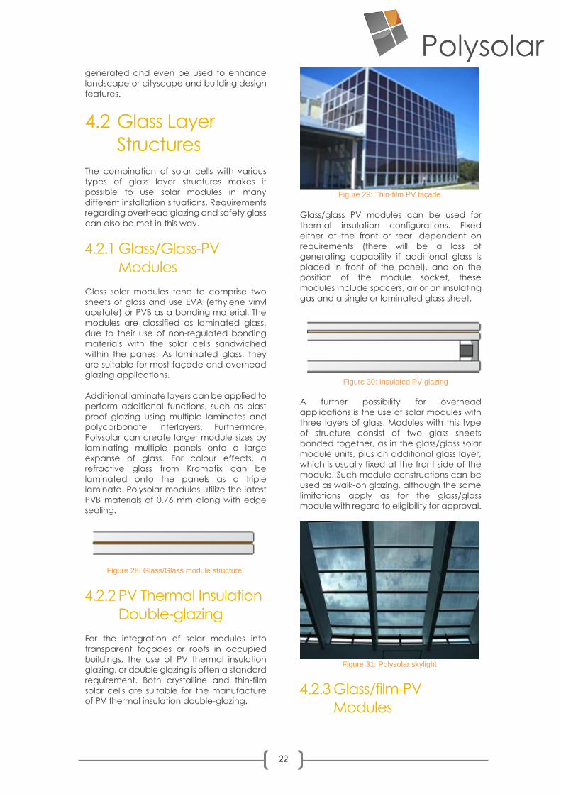
3.9 Road barriers ................................................................................................................................................. 19
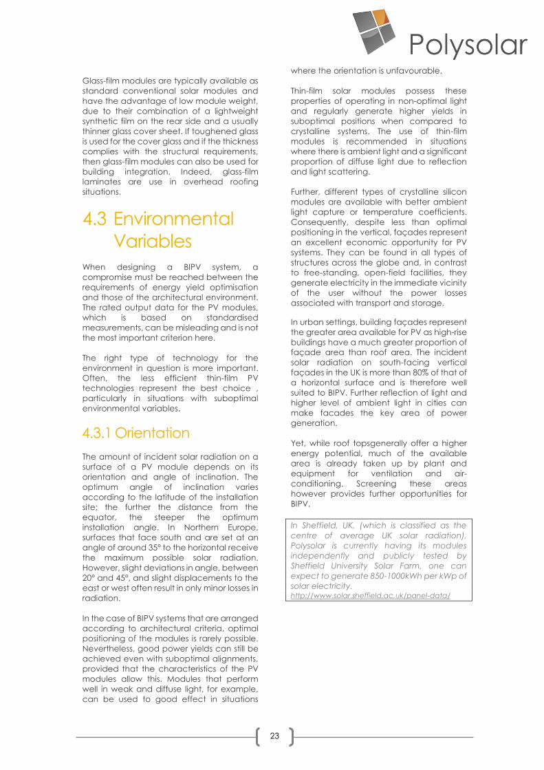
3.10 Solar automotive ..................................................................................................................................... 19
4 BIPV Design Guidelines ...................................................................................................................................... 20
4.1 Design Strategies .......................................................................................................................................... 20
4.1.1 Architecture ......................................................................................................................................... 21
4.1.2 Urban Space ........................................................................................................................................ 21
4.1.3 Landscaping ........................................................................................................................................ 21
4.2 Glass Layer Structures .................................................................................................................................. 22
4.2.1 Glass/Glass-PV Modules .................................................................................................................... 22
4.2.2 PV Thermal Insulation Double-glazing ............................................................................................. 22

5
4.2.3 Glass/film-PV Modules ........................................................................................................................ 22
4.3 Environmental Variables ............................................................................................................................. 23
4.3.1 Orientation ........................................................................................................................................... 23
4.3.2 Low-light Performance and Spectral Sensitivity ............................................................................ 24
4.3.3 Shading ................................................................................................................................................. 24
4.3.4 Temperature ........................................................................................................................................ 25
5 Economic Considerations ................................................................................................................................. 26
5.1 Panels in construction ................................................................................................................................. 26
5.2 CO2 Emissions and Regulations ................................................................................................................. 26
5.3 Feed-in Tariff .................................................................................................................................................. 26
6 Mounting System and Installation ................................................................................................................... 28
6.1 Linear Mounting Systems ............................................................................................................................ 28
6.1.1 Mullion-transom façades ................................................................................................................... 28
6.1.2 Structural sealant glazing (SSG) ....................................................................................................... 29
6.2 Point-Fixing systems ...................................................................................................................................... 29
6.2.1 Drilled spot fitting ................................................................................................................................. 30
6.2.2 Clamp fixings ....................................................................................................................................... 30
6.2.3 Undercut anchor fixings ..................................................................................................................... 30
6.3 Installation Situations.................................................................................................................................... 30
6.3.1 Sloping glazing .................................................................................................................................... 31
6.3.2 Vertical glazing .................................................................................................................................... 32
6.3.3 Glass barriers ........................................................................................................................................ 32
6.3.4 Walk-on glazing ................................................................................................................................... 32
6.3.5 Step-on glazing ................................................................................................................................... 33
7 Electrical System ................................................................................................................................................. 34
7.1 Solar panel .................................................................................................................................................... 34
7.2 Solar Array ..................................................................................................................................................... 34
7.3 Connections .................................................................................................................................................. 34
7.3.1 Serial connections............................................................................................................................... 34
7.3.2 Parallel connections ........................................................................................................................... 34
7.4 DC and AC load-break switch .................................................................................................................. 35
7.5 Inverter ........................................................................................................................................................... 35
7.6 AC load-break switch ................................................................................................................................. 35
7.7 Generation meter ........................................................................................................................................ 35
6
TABLE OF FIGURES
Figure 1: Crystalline Silicon Module ........................................................................................................................... 8 Figure 2: Polysolar thin-film a-Si Transparent Glass ................................................................................................. 9 Figure 3: Polysolar Colourless PS-CT glass ................................................................................................................. 9 Figure 4: Polysolar BIPV thin-film facade ................................................................................................................ 10 Figure 5: PV performance at varying light intensity ............................................................................................. 11 Figure 6: PV performance at different temperatures .......................................................................................... 11 Figure 7: The multiple functions of BIPV as a building material.......................................................................... 12 Figure 8: Horticultural greenhouse utilising transparent PV panels ................................................................... 13 Figure 9: Insulation benefits of Polysolar Glass ...................................................................................................... 13 Figure 10: PV weather canopy ................................................................................................................................ 13 Figure 11: Polysolar Transparent PV walkway, Barbican ..................................................................................... 14 Figure 12: Thin-film a-Si Modules .............................................................................................................................. 15 Figure 13: Kromatix colour coatings on PV panels ............................................................................................... 15 Figure 14: PV panels being used as canopies for example in petrol stations ................................................. 16 Figure 15: Carport system ......................................................................................................................................... 17 Figure 16: Polysolar PV Glass Bus Shelter Canary Wharf, London ...................................................................... 17 Figure 17: Domestic garage roof ............................................................................................................................ 17 Figure 18: Polysolar PV Glass Hathersage swimming-pool solarium ................................................................. 18 Figure 19: Polysolar Curtain wall (middle) & rainscreen façade (left and right) ............................................ 18 Figure 20: Sainsbury’s Leicester canopy ................................................................................................................ 18 Figure 21: Polysolar Skylight ...................................................................................................................................... 18 Figure 22: Domestic greenhouse with PS-C panels ............................................................................................. 19 Figure 23: Sound dampening road barrier ............................................................................................................ 19 Figure 24: Solar roof on a car ................................................................................................................................... 19 Figure 25: Rainscreen Façade ................................................................................................................................. 20 Figure 26: CIS Tower, Manchester, UK - Retrofit PV Façade ............................................................................... 20 Figure 27: Glass Facade perfect for BIPV installations ......................................................................................... 21 Figure 28: Glass/Glass module structure ................................................................................................................ 22 Figure 29: Thin-film PV façade ................................................................................................................................. 22 Figure 30: Insulated PV glazing ................................................................................................................................ 22 Figure 31: Polysolar skylight ....................................................................................................................................... 22 Figure 32: Thin-film PV as windows .......................................................................................................................... 24 Figure 33: Shading due to environmental factors ................................................................................................ 24 Figure 34: Modules in series ...................................................................................................................................... 25 Figure 35: Modules in parallel .................................................................................................................................. 25 Figure 36: Return on investment .............................................................................................................................. 27 Figure 37: Installation of Polysolar transparent modules ..................................................................................... 28 Figure 38: Linear mounting systems ........................................................................................................................ 29 Figure 39: Ventilated rainscreen cladding system and fixing ............................................................................ 29 Figure 40: Different Point Fixing systems ................................................................................................................. 30 Figure 41: Mounting panels ...................................................................................................................................... 31 Figure 42: Freestanding protective barrier ............................................................................................................ 32 Figure 43: Polysolar glazed roof ............................................................................................................................... 33 Figure 44: Solar PV Diagram ..................................................................................................................................... 36 Figure 45: Curtain wall structure .............................................................................................................................. 36

7
1 Defining BIPV
Building-integrated photovoltaics (BIPV) refers to
the concept of integrating photovoltaic
elements into the building envelope,
establishing a symbiotic relationship between
the architectural design, structure and multi-
functional properties of the building materials
and the generation of renewable energy.
The photovoltaic (PV) modules thus replace
conventional construction materials, such as
glass, taking over the function that these would
otherwise perform whilst also including the
additional function of energy production.
Although this idea is not a new concept, it has
until recently not been widely adopted due to
the extensive planning and architectural
challenges and an inertia in the building trade,
one that Polysolar aims to change.
In principle, BIPV can be used in all parts of the
building envelope. Although roof surfaces are
currently the preferred area for installing PV
elements due to their advantageous irradiation
values, façades, windows and other structures
often offer greater potential.
The ratio of façade surface area to roof surface
area increases with the building height. In
addition, the available roof area is often
reduced due to the installation of facilities and
superstructures, meaning BIPV façades are of
particular value in high-density urban centres.
Current incentives and regulations have largely
driven PV installations to date, predominantly
consisting of building-applied photovoltaics
(BAPV) systems where the PV is an addition
rather than performing any other function, for
purely financial returns.
The existing process of constructing buildings
and then bolting on renewable energy
generation devises is neither a good use of
material resources nor does it achieve the best
aesthetic, functional or cost-effective
outcomes. At Polysolar we believe that “bolt-
on” PV is a ‘stop gap’ measure until full
integration within the fabric of the building
becomes the norm. With a considered upfront
systems approach, there is no technical reason
why BIPV could not be integrated into any new
build.
Building integrated PV (BIPV) offers the potential
to make micro renewable energy generation
costs competitive with fossil fuels. By substituting
conventional building envelope construction
materials for solar PV modules, the additional
installed cost of the PV energy generation
element is marginal within the total build and in
some cases cheaper on a square meter basis.
Add on the multi-functional benefits afforded by
PV glass and the additional costs can become
non-existent. For these reasons, we believe the
future for PV is BIPV.
8
2 Building Integrated Photovoltaics With regards to the aesthetics of the building, a PV
module should have a homogeneous
appearance and either blend discretely into the
overall design or dominantly shape it.
The appearance of the PV module is essentially
determined by the type of technology used in the
PV cell and by the design possibilities offered by
the selection of materials used in the module.
2.1 Technologies
The PV market, as an innovative and rapidly
growing industry, offers a widening range of
different technologies. Generally, these can be
divided into two main groups based on the type of
manufacturing technology, namely crystalline
cells and thin-film cells. In addition, there are
several new technologies under development
based on organic (man-made) compounds and
nano-structures that offer the possibility of cheaper
and more functional photovoltaic materials in the
future. Polysolar are leaders in next generation PV
modules through the development of organic
polymer (plastic) solar cells for application as fully
transparent colourless photovoltaic windows.
2.1.1 Crystalline Silicon
Crystalline solar cells, derived from growing silicon
crystals or ingots then slicing them into
semiconductor wafers, usually consist of
approximately 150 X 150 mm (6” X 6”) square
plates with a metallic blue or black surface that is
subdivided by silver-coloured contact grids, which
collect the current. There are two key types; mono-
crystalline and poly-crystalline cells. The former
being hexagonal and higher efficiency and the
latter being square and slightly lower efficiency.
Special anti-reflective coatings can be applied to
create other metallic shades/colours. Modules are
created by connecting several silicon cells to form
larger strings.
For semi-transparent modules, light transmission
through the panels can be achieved and adjusted
by altering the spacing between the cells. Since
the size of the cells is not variable, any change in
the module size leads to a change in the overall
light transmittance or results in a suboptimal
arrangement of cells. Various shapes and pattern
variations can be achieved.
2.1.2 Thin-film Modules
Thin-film modules consist of a semiconductor, a
few micrometres thick, typically installed on
conductive glass by means of vapour deposition
with a metal backed structure. The resulting
coating is then subdivided into individual thin linear
cells; these cells are broken up by metallic or
transparent lines. The size of the modules is
predetermined by the size of the carrier plate and
is therefore difficult to divide into smaller segments.
Bespoke panel sizes can be achieved by
depositing on a smaller area of conductive glass or
by laminating multiple panels together.
Semi-transparency can be achieved in some thin-
film panels by selective removal of the PV module
material layers using laser ablation. This creates a
pattern in the panel and allows light to pass
through the gaps. By nature of removing the active
material, there is a proportional reduction in
power.. Various levels of clarity can be achieved
with finer patterning and more ablation.
The approach undertaken by Polysolar in contrast
to other companies is to utilise a variety of thin-film
materials to offer direct functionality. These include
amorphous silicon a–Si, micro-morph l a-Si/μc-Si
and Cadmium telluride CdTe.
2.1.2.1 Amorphous silicon (aSi)
This technology utilises the equivalent of powdered
silicon in very small quantities. This is vacuum
deposited along with transparent, conductive
oxides on both glass surfaces with the active PV
material between as a semiconductor. The glass is
then laminated together as a sandwich to create
a uniquely translucent module.
The PV panel allows around 20% light (T200-700)
transmission across the whole surface, without
requiring additional processing or material
wastage. Combined with our mass production
process, this makes the Polysolar PV Panels cost
comparable with conventional crystalline silicon
modules.
Figure 1: Crystalline Silicon Module

9
The modules themselves are tinted and uniquely
work on both sides, making them ideal in situations
where there is reflective light on the underside.
Polysolar also produces opaque versions of the
same module design, using the addition of a white
paint interlayer in between the laminate so the
back of the module appears as white glass and
the light is reflected internally giving a 10% uplift in
panel performance.
2.1.2.2 Micromorph (Si/µc-Si)
This technology consists of a multijunction structure
of two layers of amorphous silicon and
microcrystalline silicon. The a-Si absorbs in the blue
light spectrum and the μc-Si absorbs in the red,
with the result that the panel performance per
square metre is improved significantly. The
appearance of the opaque panels is black, while
the transparent version appears colourless.
2.1.2.3 Cadmium Telluride (CdTe)
Polysolar also uniquely manufactures a transparent
thin-film PV glazing based on cadmium telluride,
CdTe. This offers significant performance
improvements over a-Si and even micromorph
panels. Absorbing light across the spectrum, the
colourless transparency is achieved through laser
ablation to deliver a fine pixelated effect.
Polysolar also works alongside other specialist PV
and glass manufacturers, utilising other PV
technologies to achieve the highest aesthetic,
structural and performance requirements our
clients require. Polysolar can therefore offer
product variants to enable architecturally unique
bespoke BIPV solutions for most applications.
2.1.3 New Developments
Whilst to date it is not possible to create completely
clear modules, Polysolar is working on the next
generation of organic polymer solar cells (OPV)
that capture light consistently across the light
spectrum as well as in the non-visible spectrum to
create truly transparent colourless PV Glass for the
future.
2.2 Efficiency & Yield
To compare the different types of cell technology
the rated yield of each module type is determined
based on standardised measurements, usually
conducted under ‘standard test conditions’ (STC).
This involves applying a light source of 1000 W per
m2 vertically to the modules, at an ambient
temperature of 25° Celsius. For the purpose of this
measurement, the spectral composition of the light
is 1.5 AM (air mass factor)..
.
The output measured under these conditions
determines the solar element’s rated module
output that the manufacturer is obliged to state.
The ratio of the applied radiation (1000 W/m2) to
the measured values gives the efficiency of the
solar module.
Generally, the older and already highly developed
crystalline technologies still provide the highest
commercially available efficiency values of12% to
17% for polycrystalline modules and up to 20% for
monocrystalline modules. The efficiency of thin-film
technologies currently lies below these values,
typically ranging from up to 7% for amorphous
silicon and up to 12% for CdTe modules.
Current research promises further optimisation of
the yield per unit area of solar elements and these
are rising by around 1% per annum on average.
Importantly, the STC efficiencies of different PV
panelsdo not necessarily reflect the yield, or
energy output that can be derived over a year in
a given location or position.
Figure 2: Polysolar thin-film a-Si Transparent Glass
Figure 3: Polysolar Colourless PS-CT glass

10
In reality, PV installations are not exposed to
constant test conditions and consequently there
are significant variations in the amount of energy
that they actually generate.
Photovoltaic technologies performances vary in
different light intensities and temperatures. High
performance crystalline modules are optimised for
1000 W/m2 radiance but their performance tails off
significantly in lower irradiance. Thin-film
photovoltaics technologies in contrast tend to
operate optimally at 700 - 800 W/m2 radiance and
continue working down to very low radiance
levels. Unlike crystalline modules which require
direct sunlight, thin-film works in ambient and
reflected light as the individual crystals bounce the
light around within the cell.
Polysolar’s thin film modules, for example, operate
down to ~10% of sunlight ensuring they maintain
their efficiencies even on the dullest days, working
even indoors from artificial light.
The performance differentiation in different light
levels is not only important when considering the
position of the project geographically, but also in
relation to where on a building the PV panels are
sighted. PV panels on a vertical façade will receive
lower light levels than those optimally angled on a
roof. Equally, those facing north will receive less
direct light than those facing south and hence
different technologies need to be considered in
relation to the full spectrum performance they will
receive.
Conventional crystalline silicon modules tend to
need to be optimally positioned to maximise solar
radiance to operate effectively. Thin film
technologies on the other hand can often
effectively be positioned on the vertical or non-
south facing positions where they utilise ambient
light rather than direct sunlight.
Figure 4: Polysolar BIPV thin-film facade
11
Figure 6: PV performance at varying light intensity
Figure 5: PV performance at different temperatures
12
Further, while all PV cells tend to perform better at
lower temperatures, crystalline silicon cells can see
dramatically reduced performance in high
temperatures, while thin-film technologies tend to
be less affected by higher temperatures. Indeed,
there is a general avoidance of using crystalline
silicon modules in the tropics and hot desert
regions due to the high ambient temperatures
significantly impacting energy yields.
Temperature co-efficient data of the panel
technology is therefore an important consideration
when considering a BIPV project. The co-efficient
of temperature / power (%/°C) of c-Si crystalline
modules is -0.4 to -0.5 %/°C, while the thin-film a-Si
equivalent is -0.1 to -0.2 %/°C.
As panels may be mounted directly onto insulation
or offset slightly for airflow ventilation, these factors
need to be considered as module efficiency can
drop by more than half if the incorrect technology
is used. Even in the UK summer, pitched roof
mounted module temperatures can reach over 70 °C, significantly reducing performance. In contrast,
thin-film panels, and in particular, transparent or
double-glazed panels, can avoid the concerns
with high temperature build up and hence their
performance can be maintained even where
limited ventilation is possible.
2.3 Multi-functionality
Due to their mechanical properties, PV panels can
perform the functions of the building envelope in
addition to generating emission-free energy, thus
replacing/substituting for conventional
construction materials.
The extent of this multi-functionality as a building
material is determined by the design of the panel
structure, which in turn defines the technical,
economic and architectural design aspects of the
project.
By taking on additional functions, solar
construction elements can be used for various
applications in buildings, and can even be used as
a substitute for separate systems, such as shading
systems and Brise Soleil, that would otherwise be
required. Such substitutions therefore make BIPV
systems cheaper than traditional materials and
even produce a return on investment. Thus,
despite the additional electrical system and PV
material costs, building-integrated PV systems can
be in some circumstances significantly more cost-
effective than traditional construction materials.
2.3.1 Light & visual
The relationship between the interior and exterior
world is of great importance in architecture. The
use of translucent or semi-transparent solutions
combines shading with light and visual clarity with
screening. In contrast to purely opaque solutions,
the architectural design potential is increased here
to perform the function of a window. Panels are
available in semi-transparent, opaque or even a
variety of colours.
2.3.2 Sun protection
The PV panels provide sun protection, delivering
shading and glare control. The transparency can
be varied to provide the desired degree of light
transmission in accordance with a targeted
design.
Polysolar modules absorb light in the ultraviolet
(UV) wavelengths that causes bleaching and
degradation of physical objects, scorching in
plants, and sunburn. Polysolar panels have even
been proved to aid healthy plant growth.
Figure 7: The multiple functions of BIPV as a building material

13
2.3.3 Architectural design
The wide range of designs of PV panels makes it
possible to use them as architectural design
elements and can be incorporated and managed
during the design stage.
Furthermore, the innovative nature of the panels
adds to the overall image of the building and
contributes to the impressive atmosphere within.
2.3.4 Thermal Control
The temperature of a photovoltaic module can
increase significantly when the module is exposed
to radiation. The heat that the modules then
radiate into the environment can be harnessed to
provide heating or can be utilized to enhance
passive ventilation systems.
A further attribute of transparent thin-film solar
panels is in the regulation of thermal gain within a
building. The conductive coatings on the glass also
acts to reflect the infrared light spectrum,
performing the function of low emissivity glass as
used in conventional commercial office windows.
This reduces the thermal gain (g-values) also
reflecting the heat back within the building to
ensure a more consistent temperature over the
day and seasons. Heat gain is also reduced by a
combination of shading and absorption,
converting some of the light to electricity.
2.3.5 Thermal insulation
Depending on their thickness, the multi-layer glass
structures of PV modules can be used to provide
thermal insulation. In addition, most modules can
also be integrated into double or triple glazing units
or used as alternative secondary glazing as front
cladding for curtain or roof insulation elements. An
air-filled double glazed Polysolar transparent
module has u-values of 1.2 W/m2.K and as low as
0.9 W/m2.K with argon-filled double glazed units
making their thermal performance superior to most
conventional glazing systems.
2.3.6 Weather protection
The glass structure of PV modules naturally provides
weather protection. With the correct choice of
glazing layers or films in combination with the
building-integration mounting system, PV panels
can provide rain-proofing, wind-proofing, wind
load resistance and ageing resistance as well as
offering residual structural integrity to the building.
Figure 8: Horticultural greenhouse utilising transparent PV panels
Figure 10: PV weather canopy
Figure 9: Insulation benefits of Polysolar Glass

14
2.3.7 Sound insulation
PV panels can reflect or attenuate sound
depending on their construction. For this reason,
they can also be used as sound protection
elements. PV façades or roof elements already
possess sound insulating properties thanks to their
multi-layer structure, and the module design can
be adapted to meet specific local sound insulation
requirements. The sound reduction index can be
adjusted by increasing the thickness of the glazing
and by using asynchronous cover layers and
specific intermediate layers, such as
polycarbonate.
2.4 Module Design
Solar BIPV panels are generally available as
laminates made of glass/glass or metal/plastic film.
As a rule, façade and overhead glazing systems
use glass laminates only, while roofing modules are
glass/metal film or plastic/metal film.
In addition to providing protection for the solar
cells, these laminate elements can also meet
structural and design requirements.
Various parameters should be considered when
assessing BIPV suitability in a, such as:
❖ Module size
❖ Module shape (e.g. rectangles or special
shapes)
❖ Covering glass
o Glass quality
o Strength
o Structure
o Coating
o Colour
o Tinting
o Patterning
❖ Cell background or reverse side of module
❖ Transparency arrangement of solar cells in the
module, patterning, or material transparency
to give percentage light transmission
❖ Interconnections: Wiring and connectors
❖ Multi-layered superstructures such as insulated
glazing
❖ Cell colour
❖ Module aesthetics: uniformity, framing, cell
lines, etc.
2.4.1 Transparency
Transparency or semi-transparency can be
achieved in different types of PV modules using
different technologies.
The effect of transparency is commonly achieved
in the PV module by the combination of
transparent unoccupied areas and a pattern of
opaque solar cells. The arrangement and
distribution of the solar cells within the module thus
controls the degree of transparency. This makes it
possible to create interesting and innovative light
effects. If the module is required to have less
transparency, the intermediate areas not filled with
cells can also be coloured.
There are broadly three conventional approaches
to achieve semi-transparency. One is to take
individual crystalline silicon cells and embed them
in a glass laminate. The cells can bespaced
accordingly to allow the light through. The
alternative approach is taking thin-film glass
modules prior to lamination and patterning the
module using a laser to ablate (remove) the active
layer, allowing the light to pass through. The third
approach taken by Polysolar is to achieve
transparency of the active PV material by the
adoption of ultra thin-film deposition of the active
PV materials with two layers of transparent
conductive coatings. While the resultant module is
tinted, light can pass through the surface of the
module to create of transparent PV glass module
without loss in performance caused by ablation of
the materials or spacing the cells.
2.4.2 Colour Variations in the colour of solar modules can be
achieved. Conventional solar cells are generally
black or blue in the case of crystalline silicon and
brown or black with thin-film.
To achieve colour effects that differ from the cell
colour, coloured laminates, coatings or films can
be used. This makes it possible to create interesting
effects such as logos on PV modules or colours that
match the existing building.
Figure 11: Polysolar Transparent PV walkway, Barbican

15
The following methods can be used for colouring
solar panels:
❖ The use of coloured glass
❖ Use of coloured polycrystalline modules
❖ Glass with full area print (glass enamel) with
various patterns
❖ The application of a coloured laminate film
(low resistance) in semi-transparent modules
❖ Refractive-reflective coatings such as Kromatix
These creative design measures on the surface of
the panels naturally result in a reduction in the sunlit
surface area or in the reflection of some of the
incident light. The output of the solar module is
therefore always reduced. For this reason, a
compromise between design and output must
always be found when designing coloured solar
panels. To minimise the reduction in efficiency, the
coverage rate of the colour printing, or the
intensity of the colouring, should be kept as low as
possible. That said, the trade-off for colour can be
only a 5% reduction in performance.
Polysolar currently offers a full range of colour
laminates and Kromatix coated thin-film tinted
panels (transparent and opaque). These are
designed to be complementary to local building
vernacular. We also have a transparent grey
module where printed designs and colours can be
incorporated into the module.
2.4.3 Glazing Types
While most solar modules have a fixed glass type in
their design, provided there are no process-related
limits, all available quality grades and types of glass
can be used for solar modules. This means that the
structural and safety requirements for specific
types of application can be met by using
toughened glass or different thicknesses of glazing.
To ensure optimum yield, the cover glass should
preferably be white glass with a low iron oxide
content and high transmission. The lower iron oxide
content also eradicates the typical greenish tint of
the glazing.
Using structured glass for the cover glass can also
increase the yield of a solar panel. The surface of
the structured glass is made up of wave-shaped,
rounded depressions that act as light traps. Some
of the radiation that would normally be reflected
into the environment and lost, is directed back into
the cell. This increases the amount of incident
radiation and can increase the output of the solar
modules by up to 3 %. From an architectural point
of view, however, the fascination of this type of
glazing lies in its matt appearance and non-
reflective surface. Similar looks can be achieved
though sandblasting to pattern the surface.
As most BIPV glazing is laminated, it tends to meet
the structural and safety requirements of overhead
glazing. Where additional strength is required,
Polysolar recommends either using a thicker or
strengthened back glass or even triple laminating
the unit to achieve the desired requirements – such
as balcony glazing.
Polysolar uses a mixture of standard float glass on
front of its modules as well as variety of heat
treated or tempered glass. It is important to
remember that if cut ‘dummy’ BIPV panels are to
be employed in the design that not all glass can
be cut onsite.
In addition, BIPV glazing panels can be double or
even triple glazed to achieve superior thermal
insulation values. Polysolar also offers double
glazed units with a full range of rear glass achieving
u-values of less than 1.0. Note that because of the
electrical contacts, automated double glazing is
usually not possible.
2.4.4 Cell Contacts
Electrically conductive contacts are required to
connect the individual cells and super cells within
the module. Often, these are made of conductive
materials such as copper and significantly affect
the appearance of the module. However,
depending on the type of technology used, these
electrical contacts can be made invisible if
required.
Figure 12: Thin-film a-Si Modules
Figure 13: Kromatix colour coatings on PV panels

16
Polysolar’s thin-film modules have the conductive
bus bars on the edge of the glazing module so are
non-visible. The connector blocks are either
housed on the back of the module or on the
edgeof the laminate for incorporation into window
frames.
Figure 14: PV panels being used as canopies for example in petrol stations

17
3 BIPV Applications
Since BIPV modules can be structured in many
ways, there is a correspondingly large variety of
possible applications for the integration of PV
systems in and on buildings. Solar PV cells can be
incorporated into just about any glass layer
structure, so that even walk-on glazing, bullet proof
glass and thermal insulation glazing systems are
possible.
Examples of possible and existing applications
include:
❖ Solar protection fins and louvres
❖ Sun protection panels and canopies
❖ Façade cladding - rain screens, curtain walling
& rear-ventilated façades
❖ Double glazed façades
❖ Translucent or semi-transparent windows
❖ Integrated Roofing
❖ Skylights
❖ Privacy protection panels
❖ Balustrades & fencing
❖ Sliding shutters
❖ Canopy roofs
❖ Street furniture
❖ Noise protection walls
❖ Greenhouses
❖ Advertising billboards
❖ And many more
By building with PV, unique and attractive
structures can be created that deliver form and
function.
3.1 Carports One of the biggest BIPV markets is for carports.
Here the PV panels are mounted onto a car park
canopy that both protects the vehicles and
passengers from the elements, but also provides a
large area on which to generate power. With the
advent of electric vehicles (EV); where the charge
points deliver free renewable electricity, these BIPV
car park canopies are set to grow significantly.
Polysolar has developed a range of canopies that
use both transparent and opaque PV panels as the
roof. With large scale installations, these can
deliver solar for less than £1.50/Wp installed.
3.2 Street Furniture The smart cities of the future will increasingly
incorporate stand-alone structures that generate
their own power. Examples of which are park
benches that can charge mobile devices. bus
shelters that power the information screens,
walkways that can be illuminated from batteries or
cycle shelters that can recharge electric bicycles.
3.3 Sheds and Barns Why stop at shelters when complete barns can be
built of PV panels enabling a low-cost construction
to a preformulated modular design;delivering not
only sufficient energy for the building but also
enabling export to the grid.
Figure 15: Carport system
Figure 16: Polysolar PV Glass Bus Shelter Canary Wharf, London
Figure 17: Domestic garage roof

18
3.4 Conservatories
The PV glass units replace the conventional
glazing, providing a weatherproof envelope,
reducing the thermal gain, and generating
electricity.
3.5 Curtain wall & rain-
screen façades Polysolar's photovoltaic glass panels are ideal for
incorporating into building façades due to their
frameless design and aesthetic finish. They are
more efficient at non-optimal angles than
crystalline silicon panels and so ideal for a vertical
mounting system. Panels can be incorporated into
a curtain walling framework or in a bonded
rainscreen system.
3.6 Canopies
Incorporating PV into canopies and walkways is a
great way of utilising what is often a large space
more productively. One advantage of using BIPV
in a canopy structure is that the PV has dual sided
operation, increasing the overall energy yield.
Petrol stations, carports and railway stations are a
few examples of idea candidates for this solution.
3.7 Skylights, atria With colourless, transparent PV options available,
skylights and glasshouses are an ideal way of
incorporating PV into a building. Transparencies of
up to 50%are available , making this solution both
aesthetic and functional. Polysolar works in
collaboration with leading glazing companies to
offer full solutions.
3.8 Greenhouses Greenhouses have also become an opportunity
for using BIPV, offering a large surface from which
to generate renewable energy whilst also forming
part of the structure. While conventional PV panels
have been deployed in greenhouses, Polysolar’s
transparent glazing directly replaces the
Figure 18: Polysolar PV Glass Hathersage swimming-pool solarium
Figure 19: Polysolar Curtain wall (middle) & rainscreen façade (left and right)
Figure 20: Sainsbury’s Leicester canopy
Figure 21: Polysolar Skylight
19
horticultural glass and in some cases, can improve
the plant yields through selective control of the
wavelengths of light and temperature control.
3.9 Road barriers
By dampening sound, Polysolar panels are ideal for
sound barriers along motorways or main roads.
3.10 Solar automotive
With solar panels on top of your car, you will never
run out of battery! The panels can be tailored to
the required aesthetic and structural components
of the vehicle, with retractability and transparency
an option.
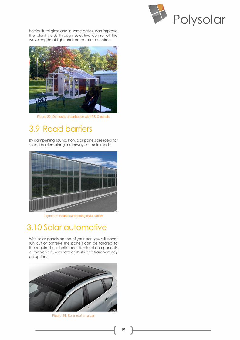
Figure 22: Domestic greenhouse with PS-C panels
Figure 23: Sound dampening road barrier
Figure 24: Solar roof on a car

20
4 BIPV Design Guidelines
The design of a BIPV system tends to be a
more complex process than a standard
‘tack-on’ PV systemsince it is necessary to
reach a consensus between optimum
operating conditions for the photovoltaic
system, the architectural context, structural
requirements, economic considerations,
and building regulations.
The rated output data for the PV modules,
based on standardised measurements, is of
only limited relevance here and even more
restrictive in the case of standard assessment
procedure (SAP) calculations as the panels
are not optimally positioned and perform
differently to framed crystalline silicon panels
In the case of BIPV, it is more important to
carefully select the right system, to tailor the
design of the PV elements to suit the
requirements of the project, and to take
these elements into consideration at an
early stage in the planning process to
achieve electrically and architecturally
optimised systems.
Particular attention must also be paid to the
planning processes and to the allocation of
responsibilities before and beyond project
completion. The planning, design and
implementation of a building-integrated
system requires the cooperation of several
different trades, such as electrical installation
and façade construction specialists, which
traditionally have very little overlap during
the detailed design stage.
It is vital, therefore, that the services provided
by the different trades are precisely defined
and demarcated. Indeed, unlike
conventional PV array installations, BIPV
projects tend to utilise specialist contractors
that need to develop familiarity with PV
modules and their application.
As a basic principle, however, the steps and
questions described in more detail below
should be observed in the planning phase
and should be reflected in the design and
implementation:
❖ Design strategy
❖ Environmental variables
❖ Multifunctionality
❖ Construction system
❖ Installation situation
❖ Glass structures
❖ Module design
❖ Electrical components
❖ Economic aspects
4.1 Design Strategies The use of renewable energy sources in
architecture is by no means a new concept,
indeed the CIS Tower in Manchester (UK)
Europe’s largest BIPV vertical installation until
recently, dates to 2005.
The use of renewable energy sources in
buildings has, however, become more
Figure 25: Rainscreen Façade
Figure 26: CIS Tower, Manchester, UK - Retrofit PV Façade

21
topical recently, as architects, property
developers, and building users become
more inclined to consider issues of resource
conservation to meet building and planning
regulations along with rising energy bills and
awareness of environmental sustainability
and global warming.
Sustainable or energy-active systems in the
building envelope present the possibility of
meeting these requirements cost effectively
using innovative applications within the
context of the proposed building or
refurbishment project. The incorporation of
renewable energy systems in buildings is now
not only a necessity to meet regulations, but
offers the added advantage of providing a
return on investment from the building
envelope.
To integrate photovoltaic systems in a
sensitive and satisfactory way, architectural
and structural factors, as well as economic
considerations, must be considered and
reconciled at an early stage.
4.1.1 Architecture
In this context, architects have the important
task of recognising, as accurately and early
as possible, the advantages and the
potential of applications such as building-
integrated photovoltaics and of presenting
these to their clients in their role as consultant
and provider of ideas.
Photovoltaic systems can be integrated in
various ways to meet the energy
performance requirement of a building.
Depending on the desired appearance,
various strategies are employed that can
influence the overall effect of the building.
Common strategies include:
❖ Adjustment
❖ Contrast
❖ Dominance
❖ Dialogue
4.1.2 Urban Space
Aesthetically pleasing BIPV solutions are
particularly needed in the field of urban
development/Smart Cities. Many local
authorities are laying down design
regulations, either separately or in the
relevant development plan, which stipulate
requirements that must observed and met
before building permission is given.
Façades, visible roof areas and street
furniture determine the character of public
spaces. By designing BIPV systems to meet
the requirements, it is possible to incorporate
PV systems in the townscape in a visually
harmonious way. Coloured designs or
invisible fixings are often required in this
context.
The integration of PV systems in existing or
even protected buildings presents a
particular challenge, since the surfaces
available for PV integration are often limited
which is why building-integrated solutions
present an excellent opportunity.
4.1.3 Landscaping
The acceptance of PV systems is determined
to a large extent by their sensitive integration
in the landscape/cityscape. Conspicuous
systems can look strange and unfamiliar and
can be perceived to spoil the landscape.
This is particularly evident in the case of
typical free-standing systems that cover
large areas of land or ‘tack-on’ panels on
domestic rooftops that are designed and
installed taking only the economic aspects
of yield optimisation into consideration.
The fundamental issues of landscape or
cityscape integration relate to the type of
installation, the method used to fix the PV
elements, the aesthetics of the PV
technology used and, not least, the choice
of installation location.
If these parameters are controlled,
innovative and congruent solutions can be
Figure 27: Glass Facade perfect for BIPV installations
22
generated and even be used to enhance
landscape or cityscape and building design
features.
4.2 Glass Layer
Structures
The combination of solar cells with various
types of glass layer structures makes it
possible to use solar modules in many
different installation situations. Requirements
regarding overhead glazing and safety glass
can also be met in this way.
4.2.1 Glass/Glass-PV
Modules
Glass solar modules tend to comprise two
sheets of glass and use EVA (ethylene vinyl
acetate) or PVB as a bonding material. The
modules are classified as laminated glass,
due to their use of non-regulated bonding
materials with the solar cells sandwiched
within the panes. As laminated glass, they
are suitable for most façade and overhead
glazing applications.
Additional laminate layers can be applied to
perform additional functions, such as blast
proof glazing using multiple laminates and
polycarbonate interlayers. Furthermore,
Polysolar can create larger module sizes by
laminating multiple panels onto a large
expanse of glass. For colour effects, a
refractive glass from Kromatix can be
laminated onto the panels as a triple
laminate. Polysolar modules utilize the latest
PVB materials of 0.76 mm along with edge
sealing.
4.2.2 PV Thermal Insulation
Double-glazing
For the integration of solar modules into
transparent façades or roofs in occupied
buildings, the use of PV thermal insulation
glazing, or double glazing is often a standard
requirement. Both crystalline and thin-film
solar cells are suitable for the manufacture
of PV thermal insulation double-glazing.
Glass/glass PV modules can be used for
thermal insulation configurations. Fixed
either at the front or rear, dependent on
requirements (there will be a loss of
generating capability if additional glass is
placed in front of the panel), and on the
position of the module socket, these
modules include spacers, air or an insulating
gas and a single or laminated glass sheet.
A further possibility for overhead
applications is the use of solar modules with
three layers of glass. Modules with this type
of structure consist of two glass sheets
bonded together, as in the glass/glass solar
module units, plus an additional glass layer,
which is usually fixed at the front side of the
module. Such module constructions can be
used as walk-on glazing, although the same
limitations apply as for the glass/glass
module with regard to eligibility for approval.
4.2.3 Glass/film-PV
Modules
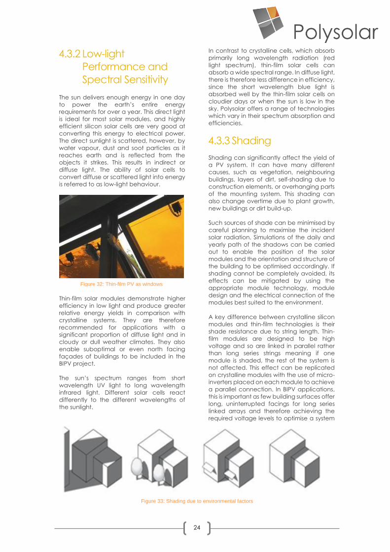
Figure 28: Glass/Glass module structure
Figure 29: Thin-film PV façade
Figure 30: Insulated PV glazing
Figure 31: Polysolar skylight
23
Glass-film modules are typically available as
standard conventional solar modules and
have the advantage of low module weight,
due to their combination of a lightweight
synthetic film on the rear side and a usually
thinner glass cover sheet. If toughened glass
is used for the cover glass and if the thickness
complies with the structural requirements,
then glass-film modules can also be used for
building integration. Indeed, glass-film
laminates are use in overhead roofing
situations.
4.3 Environmental
Variables
When designing a BIPV system, a
compromise must be reached between the
requirements of energy yield optimisation
and those of the architectural environment.
The rated output data for the PV modules,
which is based on standardised
measurements, can be misleading and is not
the most important criterion here.
The right type of technology for the
environment in question is more important.
Often, the less efficient thin-film PV
technologies represent the best choice ,
particularly in situations with suboptimal
environmental variables.
4.3.1 Orientation
The amount of incident solar radiation on a
surface of a PV module depends on its
orientation and angle of inclination. The
optimum angle of inclination varies
according to the latitude of the installation
site; the further the distance from the
equator, the steeper the optimum
installation angle. In Northern Europe,
surfaces that face south and are set at an
angle of around 35° to the horizontal receive
the maximum possible solar radiation.
However, slight deviations in angle, between
20° and 45°, and slight displacements to the
east or west often result in only minor losses in
radiation.
In the case of BIPV systems that are arranged
according to architectural criteria, optimal
positioning of the modules is rarely possible.
Nevertheless, good power yields can still be
achieved even with suboptimal alignments,
provided that the characteristics of the PV
modules allow this. Modules that perform
well in weak and diffuse light, for example,
can be used to good effect in situations
where the orientation is unfavourable.
Thin-film solar modules possess these
properties of operating in non-optimal light
and regularly generate higher yields in
suboptimal positions when compared to
crystalline systems. The use of thin-film
modules is recommended in situations
where there is ambient light and a significant
proportion of diffuse light due to reflection
and light scattering.
Further, different types of crystalline silicon
modules are available with better ambient
light capture or temperature coefficients.
Consequently, despite less than optimal
positioning in the vertical, façades represent
an excellent economic opportunity for PV
systems. They can be found in all types of
structures across the globe and, in contrast
to free-standing, open-field facilities, they
generate electricity in the immediate vicinity
of the user without the power losses
associated with transport and storage.
In urban settings, building façades represent
the greater area available for PV as high-rise
buildings have a much greater proportion of
façade area than roof area. The incident
solar radiation on south-facing vertical
façades in the UK is more than 80% of that of
a horizontal surface and is therefore well
suited to BIPV. Further reflection of light and
higher level of ambient light in cities can
make facades the key area of power
generation.
Yet, while roof topsgenerally offer a higher
energy potential, much of the available
area is already taken up by plant and
equipment for ventilation and air-
conditioning. Screening these areas
however provides further opportunities for
BIPV.
In Sheffield, UK, (which is classified as the
centre of average UK solar radiation),
Polysolar is currently having its modules
independently and publicly tested by
Sheffield University Solar Farm, one can
expect to generate 850-1000kWh per kWp of
solar electricity. http://www.solar.sheffield.ac.uk/panel-data/
24
4.3.2 Low-light
Performance and
Spectral Sensitivity The sun delivers enough energy in one day
to power the earth’s entire energy
requirements for over a year. This direct light
is ideal for most solar modules, and highly
efficient silicon solar cells are very good at
converting this energy to electrical power.
The direct sunlight is scattered, however, by
water vapour, dust and soot particles as it
reaches earth and is reflected from the
objects it strikes. This results in indirect or
diffuse light. The ability of solar cells to
convert diffuse or scattered light into energy
is referred to as low-light behaviour.
Thin-film solar modules demonstrate higher
efficiency in low light and produce greater
relative energy yields in comparison with
crystalline systems. They are therefore
recommended for applications with a
significant proportion of diffuse light and in
cloudy or dull weather climates. They also
enable suboptimal or even north facing
façades of buildings to be included in the
BIPV project.
The sun’s spectrum ranges from short
wavelength UV light to long wavelength
infrared light. Different solar cells react
differently to the different wavelengths of
the sunlight.
In contrast to crystalline cells, which absorb
primarily long wavelength radiation (red
light spectrum), thin-film solar cells can
absorb a wide spectral range. In diffuse light,
there is therefore less difference in efficiency,
since the short wavelength blue light is
absorbed well by the thin-film solar cells on
cloudier days or when the sun is low in the
sky. Polysolar offers a range of technologies
which vary in their spectrum absorption and
efficiencies.
4.3.3 Shading
Shading can significantly affect the yield of
a PV system. It can have many different
causes, such as vegetation, neighbouring
buildings, layers of dirt, self-shading due to
construction elements, or overhanging parts
of the mounting system. This shading can
also change overtime due to plant growth,
new buildings or dirt build-up.
Such sources of shade can be minimised by
careful planning to maximise the incident
solar radiation. Simulations of the daily and
yearly path of the shadows can be carried
out to enable the position of the solar
modules and the orientation and structure of
the building to be optimised accordingly. If
shading cannot be completely avoided, its
effects can be mitigated by using the
appropriate module technology, module
design and the electrical connection of the
modules best suited to the environment.
A key difference between crystalline silicon
modules and thin-film technologies is their
shade resistance due to string length. Thin-
film modules are designed to be high
voltage and so are linked in parallel rather
than long series strings meaning if one
module is shaded, the rest of the system is
not affected. This effect can be replicated
on crystalline modules with the use of micro-
inverters placed on each module to achieve
a parallel connection. In BIPV applications,
this is important as few building surfaces offer
long, uninterrupted facings for long series
linked arrays and therefore achieving the
required voltage levels to optimise a system
Figure 32: Thin-film PV as windows
Figure 33: Shading due to environmental factors

25
can prove difficult.
When linking modules in series, shading of
one module will lower the performance of
the entire string.
In contrast by linking in parallel, one module
being shaded does not affect the
neighbouring modules. This effect can be
achieved with the use of high voltage
modules or micro-inverters.
4.3.4 Temperature One feature of PV modules is their tendency
to increase in temperature rapidly, causing
a reduction In output. The output losses vary
depending on the type of cell technology.
The losses from silicon cells are
approximately 0.5 %/oC, which can have a
significant impact on array performance
and equates to more than twice the amount
lost by most thin-film modules. Polysolar
modules are Pmpp -0.21%/oC.
This temperature coefficient effect must be
considered since the standard output
measurement for solar modules is taken at 25
°C, whereas even in the UK modules
temperature commonly reach 55 °C – 70 °C
on a Summer’s day. From an energy yield
point of view, , it would be beneficial to
increase the ventilation to keep the module
temperature as low as possible. The different
module temperature issues mean that with
thin-film modules, you can insulate directly to
back of the module, thus avoiding the need
for additional ventilation. Additionally, the
temperature differentiation of a module can
be incorporated into the whole building’s
thermal control system as a passive
ventilation system.
Thin-film PV is often specified in hot climates
to overcome the temperature issues. With
crystalline silicon cells, a further issue to
consider is the thermal characteristics of
different elements of the module. For
example, in double glazed units with
embedded cells, the temperature
differential and differences in thermal
expansion can cause damage if poorly
manufactured.
Figure 34: Modules in series
Figure 35: Modules in parallel
26
5 Economic Considerations A common misconception is that the costs
for BIPV systems are significantly higher than
those for standard PV systems. New
technologies, manufacturing processes,
and component standardisation have
reduced the cost to a comparable level with
conventional PV systems.
Yet, the architecturally compatible design of
BIPV elements, using application-specific
module structures and high-quality
appearance, results in a corresponding
increase in value.
When considering the economic factors,
therefore, functional and architectural
contributions must be considered, as well as
the savings from electricity generation. Since
BIPV systems are used in place of other
construction components, the cost of
procurement and installation of these
components can be subtracted and offset
from the PV system.
Furthermore, in addition to the remuneration
received for the solar energy generated, this
energy can also be included in the energy
balance calculation for the building, in
accordance BREEAM and other regulations,
meaning costs for alternative energy
efficiency measures can be avoided. Further
effects, such as the impression that the
building makes due to its manifest
environmental awareness, can also add
value and shape its image. Therefore, it is not
unusual for the economic viability of a BIPV
system to be determined by its architectural
integration.
5.1 Panels in
construction Solar modules that are integrated into the
architecture of a building replace other
essential elements of the external skin, such
as façade cladding or shading elements,
with respect to design and function. To
achieve this, the structure of the BIPV
modules is specially designed to perform the
specific function(s) required.
When considering issues of economic
efficiency, the value of the construction
elements replaced by the modules can be
subtracted from the overall investment. To
profit from these economic benefits, this
construction component character must be
considered in the initial design phase.
Depending on the type of application, the
value of the replaced components can be
decisive with respect to the marginal
additional or even reduced cost of the
system.
5.2 CO2 Emissions
and Regulations Photovoltaic systems are extremely
environmentally friendly, since the amount
of energy they generate is significantly
higher than the amount used in the
manufacture. A further environmental
aspect is that PV installations require no fuel
and consequently emit neither dirt nor CO2.
This means that for every kilowatt-hour, the
emission of approximately seven tonnes of
CO2 is avoided. The reduction of CO2
emissions is regarded as one of the most
important measures required to combat
climate change. Today’s CO2 emissions
stem mostly from the construction and
operation of buildings. BIPV solutions are
helping to resolve this conflict by making
sustainable and emission-free energy
conversion possible at the point of use.
The combination of clean sources of
electricity, energy-efficient devices and the
expedient management of electricity
demands presents the potential for further
savings in the energy consumption of
buildings, both now and in the future.
This is also considered by regulators, which
allows the electricity supplied to the building
by the BIPV system to be included in the
calculations required to meet environmental
performance. Consequently, it may be
possible to dispense with other alternative
measures that may have been proposed for
optimising the building’s energy
consumption.
5.3 Feed-in Tariff
Most countries now provide for the
obligation of local energy supply companies
to purchase and provide remuneration for
electricity generated by PV systems. This
type of remuneration for photovoltaic
energy is paid per kilowatt-hour of electricity

27
generated, and depends on the date of
commissioning and the size of the plant. The
tariff rate varies by country.
Figure 36: Return on investment

28
6 Mounting System and Installation
The specific properties of each BIPV project,
such as location and application, along with
differing regulatory specifications for safety
and loading capacity of materials used,
combined with specifications on PV
installations within each country, will all have a
decisive impact on the BIPV technology or
panel specification employed along with the
chosen method of fixing/mounting the BIPV
panels.
The façade systems highlighted are by no
means the only solutions available, with many
clamping, bonding, and framing systems
available for all types of façade cladding.
Additionally, insulation considerations must be
taken into account as well as ducting for wiring
and connectors.
6.1 Linear Mounting
Systems
Polysolar work with several freely available
curtain walling and bonded glazing systems,
such as Nvelope, Technal, Kawneer, Comar,
SAPA, Reynaers, SAS, and Schüco. These
aluminium profiles require slight adaptations to
accommodate the wiring and connectors, but
standard products are used for both windows
and walls and can even be adapted for
opening windows.
6.1.1 Mullion-transom
façades
Mullion-transom constructions commonly
known as curtain walling, consist of vertical
mullions and horizontal transoms. The mullions
transfer the main loads and the transoms act
as horizontal bracing. The solar PV glazing
modules are set in this framework structure as
fill elements (either as a double-glazed unit or
single laminate). Clamping rails are fitted from
the outside as linear fixings for the modules with
capping over.
The circumferential profiles of the capping,
however, can shade the solar modules and
result in the accumulation of dirt and snow. The
costs for maintenance and cleaning should
also be taken into account if applicable,
particularly for roofing/skylight applications.
Additionally, the curtain walling capping
should be able to accommodate the wiring
and connectors. They can be internal or
external to the building. The gap in the
aluminium capping profile should be around
19 mm to accommodate MC4 connectors
and 11 mm for Phoenix Contact micro
connectors.
The dimensions of the façade grid will vary
from project to project and customised or fill in
“dummy” modules are sometimes required.
Mullion-and-transom façades count as
“warm” or thermally insulating façades.
Consequently, not only should the profiles be
thermally separated, but also the U-values of
the fill elements must be correspondingly low.
For this reason, PV modules can be integrated
in a thermal insulation glazing structure.
Curtain wall systems are a major consideration
in energy-efficient façade renovation projects
as well as new builds. Consideration should be
made that the system itself, whilst possibly
requiring additional initial funding, often pays
for itself within its lifetime and as such should be
regarded not as an additional expense but as
a lower lifetime cost option that can provide
the same functions and more.
Polysolar works with most commercially
available curtain walling profiles, both for
facades and overhead glazing, usually
requiring only minor adaptations to
accommodate the PV cabling in the design.
Figure 37: Installation of Polysolar transparent modules

29
6.1.2 Structural sealant
glazing (SSG)
With structural sealant glazing façades, the
solar modules are fixed in place on a metal
frame by means of circumferential load-
transferring bonds. This bonding process is no
different from standard structural facades.
This produces façades or overhead structures
with a homogeneous and smooth
appearance. Furthermore, SSG façades have
no external protruding parts, ensuring shading
and dirt traps are avoided.
These façades tend to be mainly deployed as
bonded rainscreen cladding, using aluminium
back bars, and specialist glass glues, but
bonding can equally be used in other
applications and materials.
A layer of air between the load-bearing wall
(or the insulation layer attached to it) and the
building envelope ventilates the solar modules
from the rear and can be used for laying
electrical components and connectors.
Many different types of material, such as
plaster, ceramic tiles, bricks, glass or metal can
be used for this kind of construction. Façades
can thus be created using a wide variety of
material combinations together with PV
modules or as modules alone. Additionally, LED
lighting and imaging can be incorporated into
translucent facades.
In some countries, regulations require
additional mechanical safeguards to prevent
panels installed above a height from falling. In
addition, provision for the mechanical transfer
of loads must be made.
6.2 Point-Fixing
systems
Particularly delicate designs can be achieved
using point-fixed façade systems. Typical
point-fixing systems are clamp fixings and
undercut anchor-fixing systems.
Mullion Transom Façade Structural Sealant Glazing
Mullion Transom Façade Structural Sealant Glazing
Figure 38: Linear mounting systems
Figure 39: Ventilated rainscreen cladding system and fixing
30
Although point-fixing systems cause hardly any
shading in comparison to framed systems and
are less prone to accumulating dirt, they can
only be used with certain types of solar module
or in certain applications.
6.2.1 Drilled spot fitting
Drilling in glass tends not to be possible as this
affects the semiconductor layer. Standard
thin-film modules are generally not suitable for
drilled spot fixing unless specified prior to
manufacture.
6.2.2 Clamp fixings
Clamp fixings are used in conventional PV
panel installations, where the modules are pre-
framed. In thin-film PV panels they are also
used with rubber brackets to provide support
and allow thermal expansion.
U-shaped brackets that fit around the edge of
glass panes dispense with the need to drill
holes in the glass. The fixings must overlap the
glass by at least 10 mm and the clamped area
must be greater than 1000 mm2. Depending
on application, loadings and size of panels,
fewer or greater number of clamp points or
continuous edge clamps are required to avoid
edge stress on the glass.
6.2.3 Undercut anchor
fixings
Undercut anchor fixings are mechanical point-
fixings that remain invisible, since the glass is
not drilled right through. This allows more
efficient use of the PV surface area. These
fixings generate higher stresses due the
reduced contact area of their cylindroconical
drilled holes, which means that toughened
glass, semi-tempered glass or laminated safety
glass must be used.
6.3 Installation
Situations
The demands made on BIPV systems vary
according to the type of fixing system and
installation situation. The rules governing
system installations vary by country and note
should be taken of the local regulations
applying. This report covers British guidelines
only.
Drilled spot fitting
Drilled spot fitting Clamp fixings
Clamp fixings
Undercut anchor fixings
Undercut anchor fixing system
Figure 40: Different Point Fixing systems
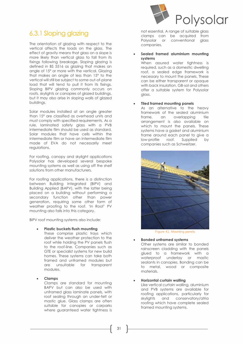
31
6.3.1 Sloping glazing
The orientation of glazing with respect to the
vertical affects the loads on the glass. The
effect of gravity means that glass on a slope is
more likely than vertical glass to fall from its
fixings following breakage. Sloping glazing is
defined in BS 5516 as glazing that makes an
angle of 15° or more with the vertical. Glazing
that makes an angle of less than 15° to the
vertical will still be subject to some out-of-plane
load that will tend to pull it from its fixings.
Sloping BIPV glazing commonly occurs on
roofs, skylights or canopies of glazed buildings,
but it may also arise in sloping walls of glazed
buildings.
Solar modules installed at an angle greater
than 15° are classified as overhead units and
must comply with specified requirements. As a
rule, laminated safety glass with a PVB
intermediate film should be used as standard.
Solar modules that have cells within the
intermediate film or have an intermediate film
made of EVA do not necessarily meet
regulations.
For roofing, canopy and skylight applications
Polysolar has developed several bespoke
mounting systems as well as using off the shelf
solutions from other manufacturers.
For roofing applications, there is a distinction
between Building Integrated (BIPV) and
Building Applied (BAPV), with the latter being
placed on a building without performing a
secondary function other than power
generation, requiring some other form of
weather proofing to the roof. ‘In Roof’ PV
mounting also falls into this category.
BIPV roof mounting systems also include:
• Plastic buckets flush mounting
These comprise plastic trays which
deliver the weather protection to the
roof while holding the PV panels flush
to the roof-line. Companies such as
GTE or specialist systems for new build
homes. These systems can take both
framed and unframed modules but
are unsuitable for transparent
modules.
• Clamps
Clamps are standard for mounting
BAPV but can also be used with
unframed glass laminate panels, with
roof sealing through an under-felt or
mastic glue. Glass clamps are often
suitable for canopies or carparks
where guaranteed water tightness is
not essential. A range of suitable glass
clamps can be acquired from
Polysolar or conventional glass
companies.
• Sealed framed aluminium mounting
systems
When assured water tightness is
required, such as a domestic dwelling
roof, a sealed edge framework is
necessary to mount the panels. These
can be either transparent or opaque
with back insulation. GB-sol and others
offer a suitable system for Polysolar
glass.
• Tiled framed mounting panels
As an alternative to the heavy
framework of the sealed aluminium
frame, an overlapping tile
arrangement is also available on
which to mount the panels. These
systems have a gasket and aluminium
frame around each panel to give a
low-profile roof. Supplied by
companies such as Schweitzer.
• Bonded unframed systems
Other systems are similar to bonded
rainscreen cladding with the panels
glued to a framework with a
waterproof underlay or mastic
sealants in canopies. Bonding can be
to metal, wood or composite
materials.
• Horizontal curtain walling
Like vertical curtain walling, aluminium
and PVB systems are available for
roofing applications, particularly for
skylights and conservatory/atria
roofing which have complete sealed
framed mounting systems.
Figure 41: Mounting panels

32
• Glazing bars
Conventional glazing bars are also
used to mount PV panels on roofs,
particularly in canopy arrangements.
These comprise an undermounting
bar, rubber gaskets with a top cap.
These can be self-supporting or
mounted on the rafters. Used with
glass laminate panels, Polysolar has
recently introduced a bespoke
glazing bar design from 123V PLC that
can span over 5 metres between
supports and has an integral conduit
for the wiring, in which to hide the
connectors.
6.3.2 Vertical glazing
Vertical glazing is defined in BS 5516 as glazing
that makes an angle of less than 15° with the
vertical. Glass at any angle to the vertical will
be subject to out-of-plane dead loads. It
commonly forms the walls, windows and
entrances of glazed buildings.
As described, BIPV can be mounted into
standard curtain walling, rainscreen cladding
and window systems. Vertical installation
applications significantly widen the scope for
PV in the urban environment making all
uprights potential power generating surfaces,
even if the energy yields are lower than a
pitched alternative.
6.3.3 Glass barriers
Barriers provide containment, this is the ability
of the glazing product to prevent persons who
accidentally fall against the glass from falling
through. Replacing conventional glass barriers
with PV panels provides a highly attractive
solution.
Three main types of barrier defined in BS 6180
use glass:
• Freestanding protective barrier
A barrier in which the glass performs all
the mechanical functions. There are
no posts; the glass is cantilevered from
the floor and often has a continuous
handrail mounted on the top edge.
Polysolar has recently introduced a
balustrade system with a floor
mounting and uninterrupted profile.
With transparent PV glazing gathering
light from both sides exterior
balustrades offer an attractive
alternative.
• Barrier with a glass infill
A barrier with a continuous handrail
and posts, which carry design loads,
and a glass pane underneath the
handrail that provides containment
but no structural support.
There are numerous off the shelf
component solutions for both
balustrades and fencing that contains
the glass. The glass and degree of
lamination can be varied for the
application such as road noise or
security barriers
• Full-height barrier
The glass forms part of or the whole of
a wall in a building. Again, there is a
range of glass available and coatings
to provide the desired look and
structure.
6.3.4 Walk-on glazing
Due to the type of use, walk-on glazing is at
greater risk of being damaged by knocks. Its
stability and fitness for use must be
demonstrated by means of structural analysis if
unfavourable loading conditions apply (1.5 kN
individual loading, 3.5 kN/m2 traffic loading).
Only laminated safety glass with at least three
layers should be used. The topmost layer
should be thicker than 10 mm and be made of
toughened or semi-tempered glass. The
bottom layers must be thicker than 10 mm and
be made of float glass or semi-tempered glass.
Figure 42: Freestanding protective barrier
33
6.3.5 Step-on glazing
Step-on glazing is usually only intended to
support loading during maintenance or
cleaning by one person at a time and must be
made of laminated safety glass panes with at
least two individual sheets.
If trafficked areas beneath step-on glazing are
not sealed off while the glazing is being walked
on, it is classified as overhead glazing.
Figure 43: Polysolar glazed roof

34
7 Electrical System In a PV array, several PV modules are usually
connected in a string to form the solar
generator. This solar generator generates a
direct current (DC), which is fed to an inverter
where the it is converted to alternating current
(AC). Provided it is not consumed or stored
directly on site, this electrical power is
registered via an electricity meter and fed into
the public supply grid. Within a large scale BIPV
project, most electricity produced will be used
on site.
7.1 Solar panel A photovoltaic module consists of several solar
cells interconnected within the module. The
way in which these internal connections are
made determines the relationship between
voltage and current and is usually limited by
process-related factors. Connecting the
individual cells in series increases the voltage,
while connecting them in parallel increases
the current generated by the module.
The electrical connection is usually made on
the rear side of the module via a connection
socket, which is normally fitted with a diode.
Edge sockets or connections on the front face
are also possible. To ensure easy and safe
installation, cables are used at the connection
sockets together with touch-proof plug
connectors that are protected against polarity
reversal.
7.2 Solar Array The solar array, or generator, is the name given
to the entire PV system, comprising all the solar
modules that are connected in a single
system. The type of connections between the
PV modules determines the cabling system,
the system stability and the necessary cable
dimensions. PV modules can be connected in
parallel or in series to form an array.
7.3 Connections As a rule, solar modules have two connection
cables with plug connectors that are
waterproof and protected against polarity
reversal. This makes it easy to connect the
different modules together. The requirements
to be met for PV module cabling are
significantly higher for direct current cables
than for alternating current cables, due to the
relevant safety regulations.
Cables for solar systems must be UV resistant,
protected against moisture and sufficiently
insulated. When determining the cross-section
of the cables that link the modules, possible
line losses in the system must be considered
and it must be ensured that the cables cannot
overheat.
The cable routing depends on the type of
façade or roof system. With rear-ventilated
façades, the connections and cables are
routed through the air gap. With mullion-
transom façades , and particularly if semi-
transparent modules are used, the cables are
often routed through the profiles of the
façade. In this case solar modules with edge
sockets can be used.
7.3.1 Serial connections When the solar modules are connected in
series, the voltage increases with each module
while the current remains constant. Since the
same current flows through all the series
connected modules, the same cable cross-
section can be used throughout.
7.3.2 Parallel connections When solar modules are connected in parallel,
the current increases with each module while
the voltage remains constant. This means that
the requirements for safe low voltage systems
can be met. On the other hand, larger cable
cross sections are required.
The interconnections for BIPV systems can be
complex due to the different orientations,
shading conditions, temperatures or even
output ratings of the individual modules. A BIPV
system should therefore be subdivided into
several segments with environmental
influences that are as similar as possible. The
smaller and more differentiated these
segments are, the more stably and efficiently
the installation will be able to run.

35
7.4 DC and AC load-
break switch The DC isolating circuit breaker allows all the
poles of the photovoltaic electricity array to be
switched off and is installed in the
interconnecting cables between the modules
and the inverter. Therefore, it is possible to
switch off the system on the direct current side,
for safety reasons.
7.5 Inverter The solar inverter converts the direct current
from the solar modules into grid-compatible
alternating current (frequency and voltage)
and thus forms the link between the PV
electricity generator and the public supply
grid.
Further important tasks carried out by this
component are the regulation and
optimisation of the output and the recording
of essential operating data.
Depending on their capacities, inverters can
be used as a central inverter for the entire
system, as array inverters for each module
array or as micro inverters for each individual
module. Inverters should be installed in
positions where they will remain as cool and
well ventilated and protected as possible. As
already mentioned, BIPV systems should be
divided into several segments or subsystems
with the same environmental influences and
output capacities. This means that centralised
inverter concepts are not usually possible. The
inverter must be selected, first and foremost, to
suit the optimum segment sizes, so that each
part of the systems has its own Maximum Power
Point (MPP) tracker. This MPP tracker ensures
that the solar array always operates within an
optimised output range.
In contrast to purely yield-optimised systems
with optimal environmental variables, the
inverters of a BIPV system that rarely operates
in maximum direct sunlight and is not optimally
aligned can often be scaled down or the
maximum module output assigned to the
inverter can be significantly exceeded.
7.6 AC load-break
switch The AC isolating circuit breaker allows all the
AC poles of the inverter to be switched off and
is installed in the interconnecting cables
between the inverter and the generation
meter. Therefore, it is possible to switch off the
system on the alternate current side, for safety
reasons.
7.7 Generation meter A generation meter is required if the solar
electricity is to be fed into the premises or grid.
In principle, this meter performs the same
function as a standard electricity consumption
meter, except that it measures the electricity
that is generated instead of the purchased
electricity. The meter readings are used to
calculate the payment received, on the basis
of Feed-in-Tariff (UK) or alternative systems
operating in different countries. Smart meters
are required to measure the amount of
electricity fed back into the grid rather than
used directly within the premise. The
connection of the solar plant to the public grid
must be carried out by a qualified electrical
specialist (MCS certified in the UK) and agreed
by the electricity supply company.
Grid connected PV systems can feed in either
all the generated electricity or just the excess
electricity that is not required on site.
Consequently, the plant operator can decide,
according to his requirements, whether to
store the generated electricity in batteries, use
the electricity directly or sell it to the electricity
supplier.
Net PV plants that have no connection to the
public grid are referred to as autonomous off-
grid PV plants or island systems, where all the
electricity generated is used by the plant
owner. As a rule, intermediate storage of the
solar electricity using batteries is necessary.
PV plants that are combined with other
systems for energy conversion are referred to
as hybrid systems. Wind power plants, diesel
generators, biogas plants, fuel cells or micro
hydro plants are typical systems.

36
Figure 44: Solar PV Diagram

37
Polysolar looks forward to receiving comments
and suggestions on this publication, which we
hope you will find useful as a tool to designing
with PV. Polysolar would be pleased to help
you with any questions or design requirements
regarding your BIPV projects.
It should be noted that these guidelines do not
refer to UK MCS specifications and are not
specific to any one manufacturers’ products.
Specific advice should be sought from the
manufacturer or certified installer before
commencing with a BIPV project.
Published by;
Polysolar Ltd
Hauser Forum
Charles Babbage Road
Cambridge
CB3 0GT
United Kingdom
Tel: +44 (0)1223 911534
www.polysolar.co.uk
Replication permissible with the written permission of
Polysolar. We acknowledge the assistance of
Odersun AG in the production of this publication.
Figure 45: Curtain wall structure