Embed Size (px)
Citation preview

H.E.T.T Thermal Engineering Lab

Babcok & Wiscok Boiler Model
Band & Block Brake Model
Band Brake Model

Bell Crank Lever
CAM Apparatus Analysis
The apparatus is designed to study the cam profile and Performance of Cam and Followers system. It consists of a shaft supported in ball bearing and driven by variable speed D.C. Motor. Various types of Cam can be mounted on this shaft. A push rod Assembly is supported vertically and various types of flowers can be attached to be pushrod. A dial gauge is provided to plot the follower’s displacement with respect to rotation of Cam. Provision is also made to vary the weight or spring compression on follower assembly so that effect of follower eight or spring force on jump can be studied. With the help of stroboscope (Not include in cope of supply)
Specifications:
• Cam – Eccentric, Tangent and circular Type
• Follower – Mashroom, Roller and Knife edge
• Weight – 100gm, 200 gm, & 500 gm
• Compression spring
• Motor – variable speed D.C Motor, ¼ H.P.
• Speed Control Unit
• Dial Gauge
• Cams & Followers are suitability hardened to reduce wear

Tachometer Cylindrical Cam
Carburetor & MPFI System
Range of Experiment:
1. Plotting and analysis of the X‐0 curve.
2. Followers bounce can be observed using stroboscope
3. To study the effect of followers weight on bounce
4. To study effect of spring compression on bounce
Service required:
• Floor Space – 0.75m x 1m at working height
• 230 V.C.A stabilised power supply

Carburetor Model
Claw Clutch Model
Conical Friction Clutch Model

Coupling Rod
Crank & Sloteed Lever Model
Double Shoe Break Model
Double Slide mechanism Model

Elipse Tracer Model
Inversion Of Four Bar Mechanism Model
Four Stroke and Two stroke Diesel Engine model

Multi Cylinder Diesel Engine Model
Four Stroke Petrol Engine Model
Francis Turbine Model

Fuel Supply System For Diesel Engine Model
Fuel Supply System For Petrol Engine Model
Kaplan Turbine Model

Knuckle& Cotter Joint Model
Multi Cylinder Petrol Engine
Odham’s Coupling Model

Pelton Turbine Model
Plate Clutch Model
Prony Brake Dynamometer Model
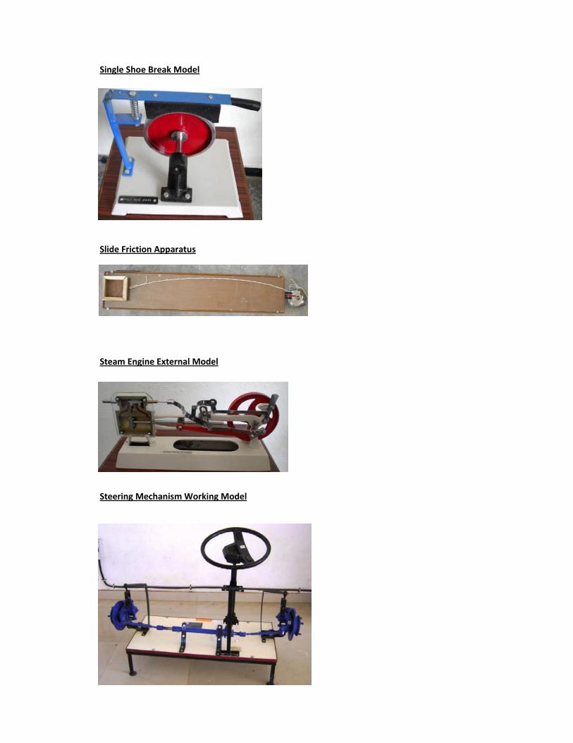
Single Shoe Break Model
Slide Friction Apparatus
Steam Engine External Model
Steering Mechanism Working Model

Triflar suspension Apparatus
Two Stroke and Four stroke Petrol Engine Model
Two Stroke Petrol Engine Cut Section Model

Various Cam Models
Various Types of Governors loaded, Porter Hartlay
Vertical Boiler Model

Worm & Worm Wheel Working Model
Model of Lanchashire Boiler Steel shell is about 75 cm. Long and 22 cm in diameter. Two large tubes known as fire tubes pass from end to end. At the front end of each tube a furnace fire grating is placed and a door is hinged. Brick work, seating and flues are shown in wood work. The boiler is complete with dead weight safety valve, manhole, mudhole, check valve high steam and low water safety valve, steam and water gauges, regulating draught doors, dampers with counter weights and chimney. The model is approximately one meterin length,37 cm. In breadth and 45 cm. High. It is specially made dissectible for demonstration purpose.
Model of Locomotive Boiler
The model is specially designed to understand the working of a locomotive steam boiler. The steel shell is of about 20 cm. Dia and 60 cm in length. The fire box is provided with a door and gate. The dissected barrel shows its inside view. Hot gases after passing through the fire tubes enter the smoke box with a door, nozzle and the blast pope. The model is approximately 100 cm in length, 45 cm high and 35 cm in breadth and is complete with whistle, steam dome, safety valve, check valve, steam regulator water and steam gauges.
Model of Chochran Boiler
This is the best known vertical type fire tube boiler. The shell is about 25 cm in diameter and 60 cm high. The cylindrical fire box is with a door and gate at its bottom. Hot gases pass from the fuel to the combustion chamber through a short flue pope and then to chimney through the tubes. At both ends of the tubes, covers are given and tubes can be cleaned after their removal. The model is complete with feed check valve, steam and water gauges, stop valve, safety valve and manhole.

Model of High Pressure boiler
Lamont Boiler
It is a properly constructed non working model made of wooden and metallic parts showing necessary parts such as boiler, feed pump, check valve, economizer, evaporator mud drum, circulatory pump, super heater, main valve, bleeder, ash pan, grate. Overall size is about 75 cm x 19 cm x 51 cm.
Loeffler Boiler
It is a properly constructed model made of wooden and metallic parts showing necessay parts such as economiser, press convection, super heater, steam outlet, radian super heater, feed pump and steam circulatory pump. Overall size is about 50 cm x 20 cm x 70 cm.
Benson Boiler Model
It is a properly constructed non working model made of wooden and metallic parts showing necessary parts such as economiser, super heater, separated evaporator and feed pump etc. Overall size is about 50 cm x 20 cm x 75 cm.
Dynamometer and calculate volumetric and thermal efficiency and draw a heat balance‐sheet.
Single cylinder Diesel Engine, Four stroke with Rope Brake Test Rig.
Single Cylinder Diesel Engine Test Rig. with Rope Brake Dynamometer
Descriptions: The Unit consists of a 4‐ stroke diesel engine coupled to a rope brake dynamometer. A water cooled brake drum along with spring balances is provided. A rope brake arrangement is provided to load the engine. Specification: 1. Diesel engine of 5 h.p. Capacity, 1500 R.P.M., 4‐ Stroke vertical, single cylinder engine. 2. Loading Device: Rope brake consisting of a brake drum of size suitable diameter & rope brake arrangement with rope, hand wheel, spring balances. 3. Fuel measuring arrangement: Consisting of a fuel tank, mounted on a strong iron stand, measurement of a fuel consumption by a burette & 3‐ way cock. Connecting tube, a stop watch. 4. Cooling water arrangement: Cooling pipes, thermocouples, measuring flask to determine the discharge of cooling water & heat carried away by cooling water. 5. Exhaust gas temperature (digital temp. indicator). 6. Air intake measurement: Air tank reservoir of orifice plate, different manometer, connecting hose.

Range of Experiment: To determine the 1. B.H.P. & I.H.P. 2. Mechanical & thermal efficiencies. 3. Air fuel ratio 4. Specific fuel consumption. 5. Heat balance sheet. 6. At various load conditions. Service Required: 1. Rigid foundation to absorb the vibration. 2. Water supply at a rate of 10 lit/ min. 3. 230 V.A.C. Supply with ear thing connection. Detailed instruction Manual accompanies.
MULTI CYLINDER FOUR STROKE PETROL ENGINE TEST RIG IC engine are widely used in automobile, domestic and industrial sector. They are classified according to cycle number of cylinder, arrangement of cylinders, duel used, and type of ignition, valve arrangement, cooling system. Test rig are used to find out the performance of an IC engine, dynamometer, fuel measuring, air intake measuring and various other arrangement with Morse test. SCOPE OF EXPERIMENT
• To determine specific fuel consumption • To determine brake horse power • To determine brake thermal efficiency • To determine mechanical efficiency
TECHNICAL DETAILS:
ENGINE:
A four stroke, four cylinder, water cooled, self start, self lubricating petrol engine provide with battery dynamics lubrications oil filter air cleaner, ignition coil, throttle cooled.
TYPE OF LOADING: Rope brake dynometer with spring balance. FUEL MEASURING SYSTEM:
Fuel measuring system consists of a fuel tank and a three‐way cock. AIR INTAKE MEASURING SYSTEM:
Air tank fitted with orifice and water manometer. MEASUREMENT OF HEAT CARRIED AWAY BY COOLING WATER:
It consist of inlet outlet piping with flow control valve water meter to measure the rate of flow of cooling water and thermocouple of measuring inlet & outlet water temperature. PANEL BOARD ARRANGEMENT:
Panel Board arrangement consisting of ignition & starting switch, ammeter, Pitot lamp a high voltage knife switch assembly for cutting off each cylinder for Morse Test and temperature measuring system.
OPTIONAL Exhaust gas calorimeter—made of M.S. including the body & the tubes for cooling water circulation and designed to get maximum temperature difference. The body of the calorimeter is insulated on all sides to prevent heat losses due to radiation. Temperature measuring system is provided to measure the cooling water inlet and outlet temperature.