Embed Size (px)
Citation preview
USLBridgeCare
Modular Expansion Joint System
www.usluk.com
Head OfficeKingston House3 Walton RoadPattinson NorthWashingtonTyne & WearNE38 8QAUnited Kingdom
t: +44(0)191 416 1530f: +44(0)191 415 4377e: [email protected]
UK OfficePanama House 184 Attercliffe RoadSheffieldS4 7WZUnited Kingdom
t: +44(0)844 417 0720f: +44(0)114 276 8782
International OfficeAl Barsha 1 B8 Building, Office 204 Dubai UAE
t: +44(0)971 4234 9752
www.usluk.com
A Company
USLBridgeCare
Modular ExpansionJoint System
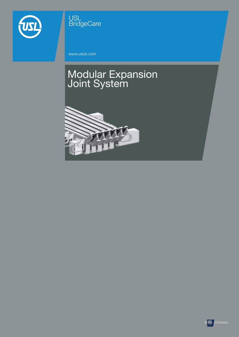
Market Leaders in Expansion Joint Technology USL BridgeCare provides a complete service to the civil engineering industry for bridge deck protection which includes the supply and installation of expansion joints and spray applied bridge deck waterproofing membranes.
The bridge expansion joint range of products caters for movements from 20mm through to 1600mm.
All of USL’s expansion joint systems have a proven track record and comply with BD33/94 standards.
The division also manufactures and applies Bridex MDP and Pitchmastic PmB spray applied waterproofing systems, both of which hold BBA HAPAS certification.
Through their technical department USL BridgeCare are able to offer a complete package of services to clients and will review a particular application from initial design to final installation to ensure the selection of the most appropriate and cost effective solution.
03
The System
The Modular Expansion Joint System (MEJS) is a mechanical device installed in bridge expansion joint openings. The primary function of the MEJS is to allow vehicle traffic to travel smoothly across large expansion joint openings. It does this by dividing the large expansion joint openings into a series of smaller openings called cells. These cells work together to accommodate the necessary thermal bridge movement (expansion and contraction) while providing a smooth riding surface for bridge vehicle traffic. The MEJS is normally used for expansionjoints with a movement range exceeding 75 mm.
The MEJS also has the secondary function of protecting the surrounding bridge superstructure and substructure. All MEJS cells are equipped with watertight sealing elements that prevent debris, water and corrosives such as de-icing chemicals from passing through bridge expansion openings and damaging superstructure and substructure components (See Figure 1).
Because bridge expansion joints open and close in the direction of traffic, a bridge skew or radiuscreates movement that is not parallel to the normal movement of the MEJS. If the direction of movement of the MEJS is not perpendicular to the joint axisbut skewed with the angle (Figure 2).
Expansion Joints with Skew
Figure 2 - Skewed Direction of Movement
Note: The direction of movement does not, in each case, have to be identical to the movement of the bridge axis.
Bridge Axis
Direction of Displacement
Joint AxisßElevation
Edge Beam
Figure 1 - Modular Expansion Joint System (MEJS)
View A
Centre Beam
Anchor Support Bar Box
Support Bar
Support Bar Box
Coil Springs
Coil Springs
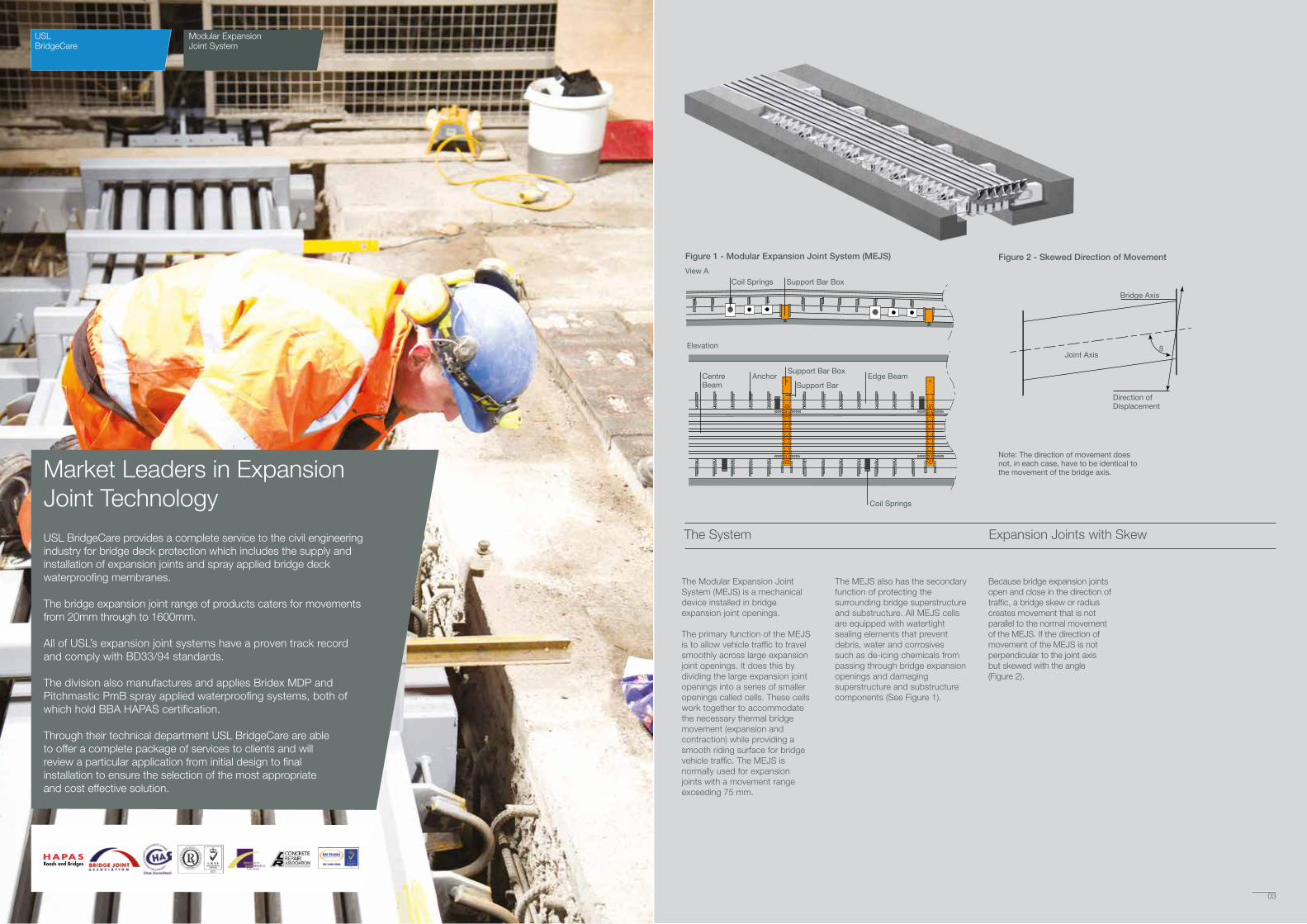
Physical Data Movement Range – The movement range of the MEJS is accommodated by the planned operating range of the neoprene seal and by the number of seals.
That is, if the planned operating range of the neoprene sealequals 80 mm, the LG12 MEJS achieves a movement range of 960 mm (12 × 80 mm = 960 mm).
Joint Width – The joint width “F” (Figure 3) is variable. It changes with MEJS movement. Joint width f (min) is the width of a closed joint. Joint widths F60, F70, and F80 are the widths of the fully open joint.
Each element has a gap of 60 mm, 70 mm & 80mm according to the planned operating range. Thus for an LG6 MEJS, there is a difference between fmin and f80 of 480 mm (6 × 80 mm = 480 mm).
Weight – The MEJS weights “G” shown in Figure 3 are mean values that vary, depending on design details.
Support System In the Single Bar – LG MEJS design, all centre beams are supported by a single support bar. Elastic, prestressed sliding elements are contained by brackets / stirrups welded to the centre beam at a spacing based on the design code applied. The same elastic, prestressed sliding elements are used inside the support bar boxes.
This support system permits an optimum load transmission while attaining the flexibility to provide movement in three different directions (See Figure 5).
Control SystemAlong with the elastomeric profiles, elastomeric control springs coordinate the individual movements to form a dynamic system that simultaneously absorbs braking and accelerating forces. The reaction of these controlling forces on the joint edges can be assumed to act in the direction of displacement with the following maximum values: Tension – max. 3 KN/m; Compression – max. 4 KN/m (See Figure 6).
04
USLBridgeCare
Modular ExpansionJoint System
05
Support System & Components
Type B1 B2 H F(min) F60 F70 F80 G(WT) (mm) (mm) (mm) (mm) (mm) (mm) (mm) (kg/m) LG2 400 400 400 140 260 280 300 150 LG3 480 300 400 220 400 430 460 210 LG4 560 300 400 300 540 580 620 250 LG5 640 300 400 380 680 730 780 290 LG6 720 300 400 460 820 880 940 410 LG7 800 300 420 540 960 1030 1100 500
LG8 880 300 440 620 1100 1180 1260 596
LG9 960 300 450 700 1240 1330 1420 745
LG10 1040 300 460 780 1380 1480 1580 1060
LG12 1200 300 500 940 1660 1780 1900 1340
Standard Single Bar – LG
Component
Description Centre Beam/ Edge Slide Slide Support Bar Control Strip Seal Centre Beam Support Bar Beam Spring Bearing Box Spring Gland Bracket
Material ASTM A 572 ASTM A 572 Natural Nylatron ASTM A 500 Polyurethane Neoprene ASTM A 36 A 588 A 588 Rubber/PTFE A 36 Foam ASTM A572 DIN ST52-3 DIN ST52-3 A 572 D 2628 DIN ST52-3
Figure 4 - Modular Expansion Joint Components and Construction Materials
Figure 3 - Modular Expansion Joint Types & Sizes
h
B1 B2F
Expansion Sections
TechStar Beam70 x 140
TechStar A3-500Shape
SlidingSpring
SlidingBearingSliding
BearingSlidingSpringJoistJoist Box
Figure 5 - Support System
B
B
Section B-BWelded Bracket Option
Section B-BBolted Bracket Option
Figure 6
Bridge Deck Waterproofing
USLBridgeCare
Modular ExpansionJoint System
06 07
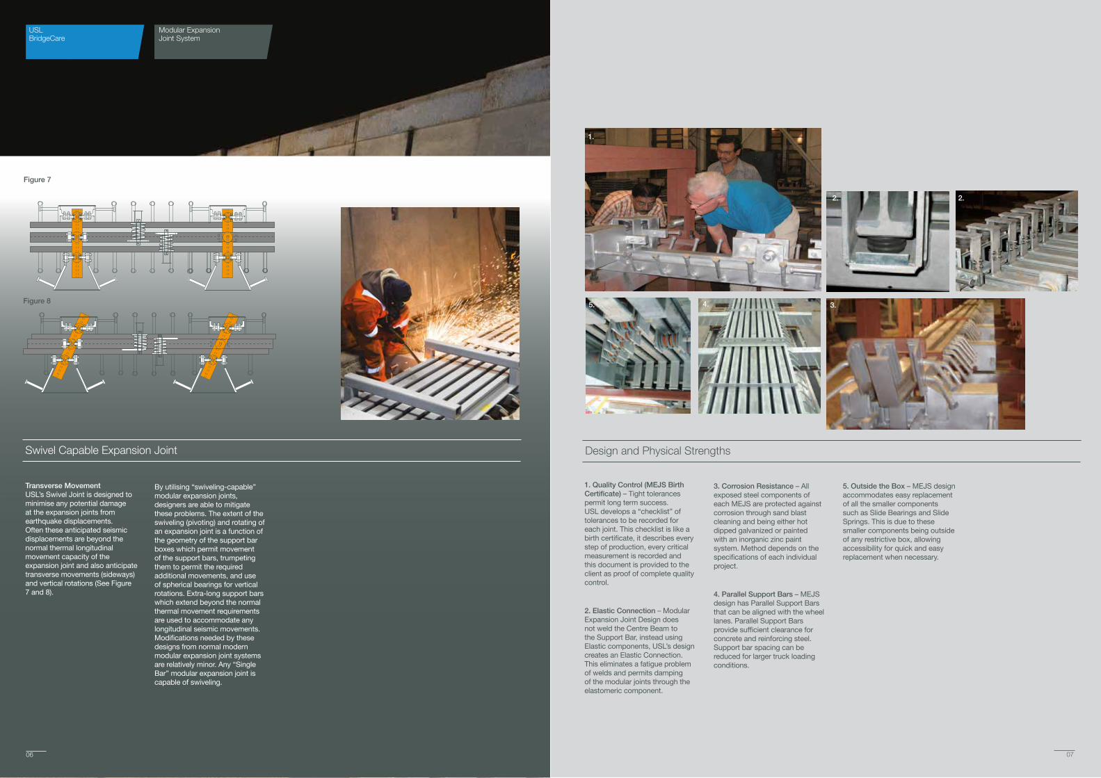
Transverse Movement USL’s Swivel Joint is designed to minimise any potential damage at the expansion joints from earthquake displacements. Often these anticipated seismic displacements are beyond the normal thermal longitudinal movement capacity of the expansion joint and also anticipate transverse movements (sideways) and vertical rotations (See Figure 7 and 8).
By utilising “swiveling-capable” modular expansion joints, designers are able to mitigate these problems. The extent of the swiveling (pivoting) and rotating of an expansion joint is a function of the geometry of the support bar boxes which permit movement of the support bars, trumpeting them to permit the required additional movements, and use of spherical bearings for vertical rotations. Extra-long support bars which extend beyond the normal thermal movement requirements are used to accommodate any longitudinal seismic movements. Modifications needed by these designs from normal modern modular expansion joint systems are relatively minor. Any “Single Bar” modular expansion joint is capable of swiveling.
Swivel Capable Expansion Joint
Figure 7
Figure 8
1. Quality Control (MEJS Birth Certificate) – Tight tolerances permit long term success. USL develops a “checklist” of tolerances to be recorded for each joint. This checklist is like a birth certificate, it describes every step of production, every critical measurement is recorded and this document is provided to the client as proof of complete quality control.
2. Elastic Connection – Modular Expansion Joint Design does not weld the Centre Beam to the Support Bar, instead using Elastic components, USL’s design creates an Elastic Connection. This eliminates a fatigue problem of welds and permits damping of the modular joints through the elastomeric component.
3. Corrosion Resistance – All exposed steel components of each MEJS are protected against corrosion through sand blast cleaning and being either hot dipped galvanized or painted with an inorganic zinc paint system. Method depends on the specifications of each individual project.
4. Parallel Support Bars – MEJS design has Parallel Support Bars that can be aligned with the wheel lanes. Parallel Support Bars provide sufficient clearance for concrete and reinforcing steel. Support bar spacing can be reduced for larger truck loading conditions.
5. Outside the Box – MEJS design accommodates easy replacement of all the smaller components such as Slide Bearings and Slide Springs. This is due to these smaller components being outside of any restrictive box, allowing accessibility for quick and easy replacement when necessary.
Design and Physical Strengths
1.
2. 2.
4.5. 3.

USLBridgeCare
Modular ExpansionJoint System
08
Project:
Benica Martinez Bridge
Location: Martinez, California, USA
Product: 80 metres (4 joints of 8-cell modular)
Project: Mohammed Hanif Flyover
Location: Dhaka, Bangladesh
Product: 312 metres (31 joints of 8-cell modular)
Project: Hyderbad Outer Ring Road
Location: Hyderbad, India
Product: 300 metres (30 joints of 2-cell modular)
Project: Lusail Bridge to the Pearl
Location: Doha, Qatar
Product: 314 metres (31 joints of 3-cell modular)
Project References
Benica Martinez Bridge Hyderbad Outer Ring Road
Lusail Bridge to the Pearl
Mohammed Hanif Flyover
09
USL Group
USL BridgeCare are part of the USL Group of companies - a global manufacturer and installer of specialist construction products offering turnkey solutions for bridges, tunnels, car parks, roofs, utilities, oil & gas projects.
Additional Products
USL BridgeCare offer their clients a range of UK Highways Agency registered bridge expansion joints along with high performance waterproofing systems:
• Uniflex - Buried Joint
• FEBA - Asphaltic Plug Joint
• Bridflex NJ - Nosing Preformed Compression Seal
• Britflex BEJ - Elastomeric In Metal Runners
• Britflex UCP - Footbridges and Elevated Structures
• Transflex - Reinforced Elastomeric Joints
• Britdex MDP & CPM Tredseal - Methyl Methacrylate (MMA) Spray Applied Waterproofing
• PmB - Polyurethane Spray Applied Waterproofing
BridgeCare
StructureCare11
General information
The FEBA joint extends to the full depth of surfacing and is installed after the carriageway and verge construction has been completed. Typical construction is indicated in Figure 1. The width of the FEBA is selected depending upon the bridge deck movement factors and the nature of the traffic using the structure. Optimum movement capacity is attained in joints 500mm nominal width and no less than 100mm deep. The materials are applied hot and in fluid condition, with temperatures up to 180°C - consequently careful consideration should be made by the Engineer before utilising FEBA in the vicinity of services of any Statutory Authority unless suitably protected.
Binder compounds are classified as thermoplastic materials and consist of a blend of polymer modified bitumen, mineral fillers and chemical additives.
FEBA utilises a nominal three size aggregate mix of 20mm (nominal) graded chippings. In joints less than 100mm deep, graded aggregate with smaller sized stone may be selected.
Drainage may be built into the joint as a pressure relief system to the adjacent road construction. The use of drainage is designed to protect the surfacing and deck waterproofing from the effects of water trapped adjacent to the asphaltic plug joints, however it should be noted that it is not essential to the correct functioning of the FEBA joint nor is it a substitute for positive deck drainage.
Conventionally pressure relief is installed along the joint on the upstream face, most usually when the FEBA is at the low end of a bridge deck (see figure 1). In this instance it is recommended that in-joint drainage is used in conjunction with a more positive and larger capacity ‘Dri Deck’ drainage system, supplied by Pipeline and Drainage Systems.
Standard metal bridging plates are suitable for up to a 45mm maximum gap opening - for larger gaps, it is recommended that wider plates of a heavier gauge be used. (As a general guide please refer to Table 1).
Drainage channel
Dri-Deck drainage unit (optional)
03
Figure 1
500mm nominal
Bridging plate
Binder
Caulking
FEBA Joint Surfacing
Bridge deck
Britdex MDP waterproofing
Installation
i) The surfacing is cut to the specified width in the carriageway using a floor saw and a trench is excavated.
ii) This cut-out together with the previously formed recess in the verge/central reserve is cleaned and dried with hot compressed air.
iii) The expansion gap is then caulked and the deck sealed with hot binder. If specified, in joint hydraulic relief is installed, metal bridging plates inserted over the gap and the entire trench tanked with binder.
iv) The aggregate is heated and pre-coated with the binder before being placed into the trench. The layer is then flooded with binder before subsequent layers are placed. The joint is allowed to cool before the final layer is applied—this is stone rich, brought marginally above the road surface and then compacted to the level of the adjacent carriageway.
v) Finally the joint is flooded with binder to the finished profile and allowed to cool to ambient temperature. Normally the joint can be trafficked in 3-4 hours, but this will depend on the ambient temperature, depth of joint and the general weather conditions.
vi) A final application of binder may be necessary to blend in any small interstices which may appear on the surface of the joint whilst cooling.
vii) Anti skid dressing is applied to the joint.
At the onset of unacceptably wet weather conditions or for example at the end of normal working hours, the joint construction may be suspended and continued at a later stage.
Technical & Advisory Services Further technical information may be obtained on request and consultation is encouraged to ensure choice of materials selected and detailing is optimised to suit in-service performance requirements and economic solutions.
Health & Safety USL operate a strict health and safety policy and details are available on request.
Note:The colours used in the illustration may not be indicative of the finished product. USL reserve the right to update and improve the FEBA joint and its specification without notice and Engineers and Contractors should satisfy themselves that they have full and up to date information.
USLBridgeCare
FEBA Joints
06
Additional information
The FEBA joint is also approved in the following countries
• Ireland
• Hong Kong
• Singapore
• China
• Brunei
• Philippines
• Russia
• Malaysia
• Indonesia
• Kuwait
• Denmark
• Greece
• Switzerland
• Australia
• South Africa
viiiii iv
ii
FEBA joint extends across the full length of the carriageway and into the verges.
v
Britflex BEJ Installation of Britflex BEJ on Westminster Bridge, London, UK
Pitchmastic PmB
Transflex
Britdex MDP
Britflex UCP
FEBA
Our Brands
wwww.usluk.com
Head OfficeKingston House3 Walton RoadPattinson NorthWashingtonTyne & WearNE38 8QAUnited Kingdom t: +44(0)191 416 1530f: +44(0)191 415 4377e: [email protected]
UK OfficePanama House 184 Attercliffe RoadSheffieldS4 7WZUnited Kingdom t: +44(0)844 417 0720f: +44(0)114 276 8782
International OfficeAl Barsha 1 B8 Building, Office 204 Dubai UAE t: +44(0)971 4234 9752
www.usluk.com