Embed Size (px)
Citation preview
1
Head Tracking Using Stereo
Karthik Narayanan
Abstract
A different perspective to head tracking, one of
the more studied topics in computer vision is
presented here. The heavy reliance of
contemporary head trackers on intensity images
is countered here. The algorithm presented here,
uses stereo data to track the head of a moving
subject. This is used to achieve effective and
accurate foreground segmentation. The head is
modeled as an ellipse and tracking is done using
constant velocity prediction. The depth
information obtained from the stereo algorithms
is used to predict the size of the head accurately.
1 Introduction Head tracking is an active area of research in
computer vision and several successful
implementations of it have been carried out in
the past. Most of these have extensively banked
on intensity images that are rendered unreliable
when the lighting is variable and in the presence
of clutter. This though has been driven by the
non-availability of real time stereo cameras, till
recently. Most of these algorithms rely on
intensity edges [1] or using skin color [2] to
track the subject’s head. A few others rely on
mathematical models that involve subspace
projection, such as PCA[3] and employing shape
and contour models.
Though substantial work has been done in
head tracking, stereo has not been used
extensively for the same. Besides annulling the
sensitivity to light variations, it enables the
localization of the head in 3-D space. This would
find extensive use in “smart room” based
applications.
[4] Uses stereo only for tracking, but uses a
very complicated model that does not acquire
fast movements. Stereo has also been used in
multimodal head tracking where it happens to be
ones of the cues used along with other cues such
as color, as in [5]. Again these rely on intensity
based measurements. The algorithm used here is based on the
foreground segmentation as proposed in [6]. But
instead of fitting to a simple torso model,
constant velocity prediction and disparity based
scale prediction is used here in predicting the
location and size of the head. An elliptical head
tracker is used here. This is one step closer to
localizing the subject’s head in 3-D space.
Similar techniques have been used in [7] for
people (and not head) tracking though.
The report is organized as follows: Section 2
describes briefly the stereo correspondence
algorithm used and various associated
constraints. Section 3 describes the foreground
segmentation algorithm in fair detail. Section 4
would describe in detail the elliptical head
tracker used with the scale and position
prediction equations. The results and their
analysis is provided in Section 5 with the
concluding remarks in Section 6.
2 Stereo Algorithm The correlation based stereo algorithm is used
here. Simplicity and real-time implementation
are motivating factors in the choice of this
algorithm over other stereo matching algorithms.
It is intended to study the various modifications
of this algorithm, with multiple windows and
sub-pixel resolution and thus stereo cameras
were not employed to yield the disparity images
directly.
A sequence of left and right rectified images
was obtained and the correlation based stereo
algorithm as in [8] was implemented. The basic
idea is tiling the left image with windows and
searching for its best match in the right image,
on the basis of an error measure. The Sum of
Squared differences (SSD) is used here, along
with a rectangular window of size 15 and a
maximum displacement of 64 pixels.
The choice of the window size proved to be
critical in this case, as the issue of addressing
depth discontinuities was critical. A very small
window yielded an unreliable disparity image
while a large window smoothed the disparity
map, hampering detection of edges. Lack of
texture in a test image affects the performance of
the stereo algorithm, yielding unreliable
disparities in the disparity image. This is one
issue to be addressed before the segmentation is performed, as discussed in the following section.
2
There were a few palpable shortcomings in this
algorithm, thus requiring a few modifications as
discussed in Section 5.
3 Segmentation algorithm This section describes the foreground-
background segmentation used to obtain the
subject in the foreground. This is akin to the one
used in [6], where every pixel in the disparity
image is modeled as a Gaussian with mean µ and
standard deviation σ. This is tantamount to
modeling depth as against traditional techniques
of modeling intensity values as Gaussians. As
the very purpose of this exercise is to reduce the
reliance on intensity values, the latter is not used
for segmentation. Besides, this technique is more
intuitive, where any pixel closer (higher
disparity) is classified as foreground and the rest
as background.
Once the depth model of the background is
obtained, segmentation can be performed
accurately. This though is hampered by the
unreliability in the disparity images, induced by
the lack of texture in the test images. To counter
this, the unreliable pixels in the disparity image
are identified as those with a standard deviation
σij>T, where ‘T’ is a pre-determined threshold (2
in this case).
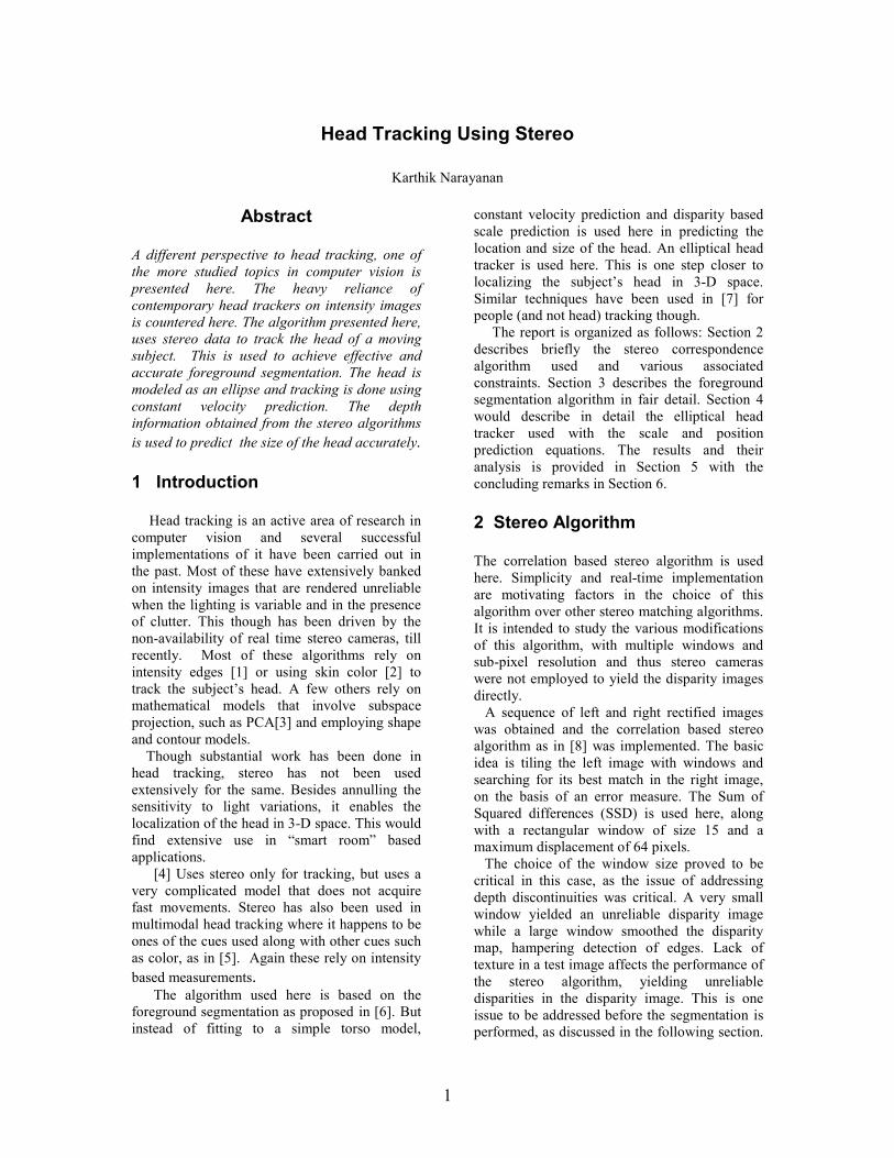
Figure 1: Top left: Image used to model
background. Top Right: Disparity image
obtained from stereo algorithm. Bottom left:
Unreliable pixels (in white), σij>2. Bottom right:
Mean image obtained after modeling.
The means and the standard deviations of the
of the images are estimated as the sample means
and sample standard deviations given by (for
pixel i, j ):
Once the means and standard deviations for the
background images are obtained, the unreliable
pixels are determined, i.e. those with a standard
deviation greater than T (2 in this case).
The segmentation for the reliable pixels is
simple. All those pixels in the disparity image (to
be segmented), with a disparity greater than the
mean by a standard deviation, are considered as
foreground pixels. As the same image of the
background is used to model it, any reliable pixel
would ideally have the same disparity for all the
considered background images (25 used here).
Thus ideally the mean µ for each reliable pixel
would be the disparity value at that pixel and the
standard deviation would be zero. Even
otherwise, the mean disparity would be close to
the test images’ disparities. Thus any pixel in the
foreground would have a disparity greater than
the mean by one standard deviation atleast.
Figure 1 illustrates this where the image
constructed with the mean disparity values for
each pixel, is very similar to the original
disparity image.
Considering the fact that our region of interest
(human) is a continuous blob of pixels, all the
unreliable pixels are considered to be
foreground. Figure 1 shows the unreliable pixels
in the test images used.
The segmentation algorithm can thus be
summarized as:
1. Using 25 images, the background is
modeled as a Gaussian with mean µ and
standard deviation σ.
2. All pixels having σij >T (2 in this case),
are classified as unreliable pixels.
3. In every subsequent disparity image,
classify each
a. Reliable pixel as foreground if
the pixel’s disparity value
DIij > µij + σij
b. Unreliable pixel as foreground
Once the foreground segmentation is
achieved, connected components algorithm is
executed, enforcing the size constraint (retaining
3
the bigger blobs), to obtain the blob of the region
of interest. Also morphological operations such
as closing (dilation followed by erosion) are
performed to address occlusions. Thus a binary
image is obtained by retaining the largest
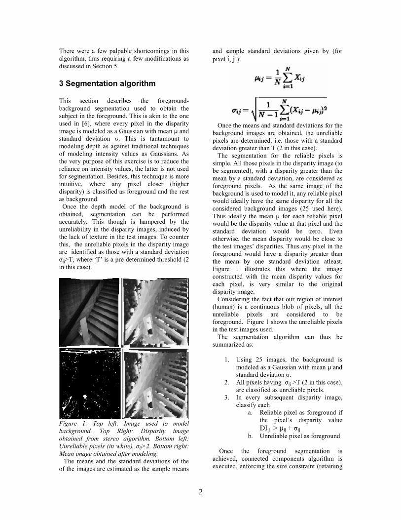
component alone. An edge detector is then
employed to obtain the edges of the region of
interest (human body). These are shown in
Figure 2.
Figure 2: Top left: Test image used for
segmentation. Top right: Corresponding
disparity image (histogram equalized for better
viewing). Bottom right: Binary image after
connected components. Bottom left: Edge
obtained after edge detection (image modified
for better viewing).
4 Tracking
The projection of the head on a plane can be
closely modeled by an ellipse. Two parameters
describe the state of the ellipse in each frame:
center and the size. Equation of an ellipse is
given by:
(x-xc) 2 + (y-yc)
2 = 1
a2 b
2
The center of the ellipse is described by the
image coordinates (xc, yc) and the scale (a) by the
length of the minor axis of the ellipse. The major
axis length (b) is a multiple of the minor axis
length. This ratio is called the aspect ratio which
when set to unity transforms the ellipse in to a
circle (as was the case in the experiments
conducted here). The outline of the head, as
shown in Figure 2 (bottom right), is to be
modeled as an ellipse. For each frame, the most
likely position of the ellipse is determined as
stated in [1]. The scale though, is determined
using the already available disparity maps.
The position of the ellipse is updated in each
image in to the one with the maximum
likelihood, i.e. to one that has the maximum
normalized sum about the circumference of the
ellipse.
The likelihood P is given by:
Here pi are the pixel values along the
circumference of the ellipse, xp ,yp being the
center of ellipse and xc and yc denoting the
search range (60 pixels here). N is the number of
pixels on the ellipse’s circumference. The scale
is predicted with the knowledge of the disparity
values, as stated below..
The scale of the ellipse in a given frame can
be used to predict the scales in the subsequent
frames, by using the disparity values in the
current and the next frame. The projection of the
head of a subject in motion decreases in size
when moving away from the camera and
increases when moving towards the camera. At
different positions, these would have unique
disparities, that can be exploited to yield the
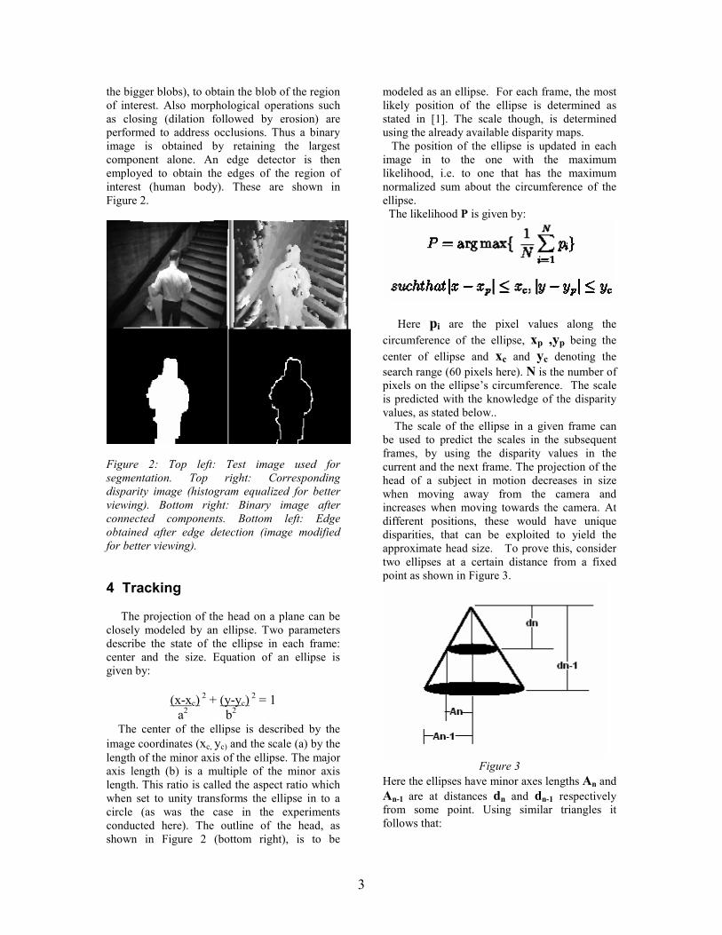
approximate head size. To prove this, consider
two ellipses at a certain distance from a fixed
point as shown in Figure 3.
Figure 3
Here the ellipses have minor axes lengths An and
An-1 are at distances dn and dn-1 respectively
from some point. Using similar triangles it
follows that:
4
This is analogous to the motion of the subject
away from the camera in frames ‘n-1’ and ‘n’.
Thus the scale of the ellipse in frame ‘n’ is:
where the d’s are normalized disparities of the
human head in frames ‘n’ and ‘n-1’. The
normalized disparities are obtained as follows:
a. Find the pixels corresponding to the
human blob as in Figure 2, bottom left.
b. Obtain the disparities of these pixels in
the corresponding normalized disparity
image, i.e. maximum disparity is unity.
c. Take the statistical mode of these
disparities as the required normalized
disparity ‘d’
As for the prediction of the positions, constant
velocity prediction as in [1] is used here. It is
assumed that the object of interest approximately
moves the same between two consecutive
frames, as it did between the previous two
frames. Thus the x and y co-ordinates of the
ellipse’s center are updated with each frame as:
where ‘n’ is the current frame. A local search
about the estimated center of the ellipse is
conducted to obtain the most likely position for
the ellipse. The performance of the tracker
though is heavily reliant on the initial scale
chosen, which needs to be accurate.
5 Results and analysis
The above mentioned algorithm was run on a
set of rectified images obtained from a database
used for people tracking [9]. A set of 25 images
of the background was used to generate the
background model.
To check the performance of the scale
prediction technique mentioned above, two
sequences that involved the subject walking
towards and away from the camera was
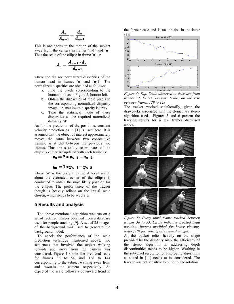
considered. Figure 4 shows the predicted scale
for frames 36 to 54, and 128 to 144
corresponding to the subject walking away from
and towards the camera respectively. As
expected the scale follows a downward trend in
the former case and is on the rise in the latter
case.
Figure 4: Top: Scale observed to decrease from
frames 36 to 53. Bottom: Scale, on the rise
between frames 129 to 143
The tracker worked satisfactorily, given the
drawbacks associated with the elementary stereo
algorithm used. Figures 5 and 6 present the
tracking results for a few frames discussed
above.
Figure 5: Every third frame tracked between
frames 36 to 53. Circle indicates tracked head
position. Images modified for better viewing.
Refer [10] for viewing all original images.
As the tracker relies heavily on the shape
provided by the disparity map, the efficiency of
the stereo algorithm in addressing depth
discontinuities needs to be higher. Working in
the sub-pixel resolution or employing algorithms
as stated in [11] needs to be considered. The
tracker was not sensitive to out of plane rotation
5
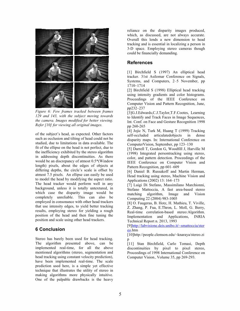
Figure 6: Few frames tracked between frames
129 and 143, with the subject moving towards
the camera. Images modified for better viewing.
Refer [10] for viewing all original images.
of the subject’s head, as expected. Other factors
such as occlusion and tilting of head could not be
studied, due to limitations in data available. The
fit of the ellipse on the head is not perfect, due to
the inefficiency exhibited by the stereo algorithm
in addressing depth discontinuities. As there
would be an discrepancy of atmost 0.5*(Window
length) pixels, about the edges of objects at
differing depths, the circle’s scale is offset by
atmost 7.5 pixels. An ellipse can easily be used
to model the head by modifying the aspect ratio.
The head tracker would perform well in any
background, unless it is totally untextured, in
which case the disparity image would be
completely unreliable. This can also be
employed in consonance with other head trackers
that use intensity edges, to yield better tracking
results, employing stereo for yielding a rough
position of the head and then fine tuning the
position and scale using other head trackers.
6 Conclusion
Stereo has barely been used for head tracking.
The algorithm presented above, can be
implemented real-time, for all the above
mentioned algorithms (stereo, segmentation and
head tracking using constant velocity prediction),
have been implemented real-time. The scale
prediction used here, is a simple yet effective
technique that illustrates the utility of stereo in
making algorithms more physically intuitive.
One of the palpable drawbacks is the heavy
reliance on the disparity images produced,
which, as discussed, are not always accurate.
Overall this lends a new dimension to head
tracking and is essential in localizing a person in
3-D space. Employing stereo cameras though
could be financially demanding.
References
[1] Birchfield S (1997) An elliptical head
tracker. 31st Asilomar Conference on Signals,
Systems, and Computers, 2–5 November, pp
1710–1714
[2] Birchfield S (1998) Elliptical head tracking
using intensity gradients and color histograms.
Proceedings of the IEEE Conference on
Computer Vision and Pattern Recognition, June,
pp232–237
[3]G.J.Edwards,C.J.Taylor,T.F.Cootes, Learning
to Identify and Track Faces in Image Sequences,
Int. Conf. on Face and Gesture Recognition 1998
pp 260-265
[4] Jojic N, Turk M, Huang T (1999) Tracking
self-occluded articulatedobjects in dense
disparity maps. In: International Conference on
ComputerVision, September, pp 123–130
[5] Darrell T, Gordon G, Woodfill J, Harville M
(1998) Integrated persontracking using stereo,
color, and pattern detection. Proceedings of the
IEEE Conference on Computer Vision and
Pattern Recognition, pp 601–609
[6] Daniel B. Russakoff and Martin Herman,
Head tracking using stereo, Machine Vision and
Applications (2002) 13: 164–173
[7] Luigi Di Stefano, Massimilano Marchionni,
Stefano Mattoccia, A fast area-based stereo
matching algorithm, Image and Vision
Computing 22 (2004) 983-1005
[8] O. Faugeras, B. Hotz, H. Mathieu, T. Viville,
Z. Zhang, P. Fua, E.Thron, L. Moll, G. Berry,
Real-time correlation-based stereo:Algorithm.
Implementation and Applications, INRIA
Technical Report n. 2013, 1993
[9]http://labvisione.deis.unibo.it/~smattoccia/ster
eo.htm
[10]http://people.clemson.edu/~knaraya/stereo.zi
p
[11] Stan Birchfield, Carlo Tomasi, Depth
discontinuities by pixel to pixel stereo,
Proceedings of 1998 International Conference on
Computer Vision., Volume 35, pp 269-293.