Embed Size (px)
Citation preview
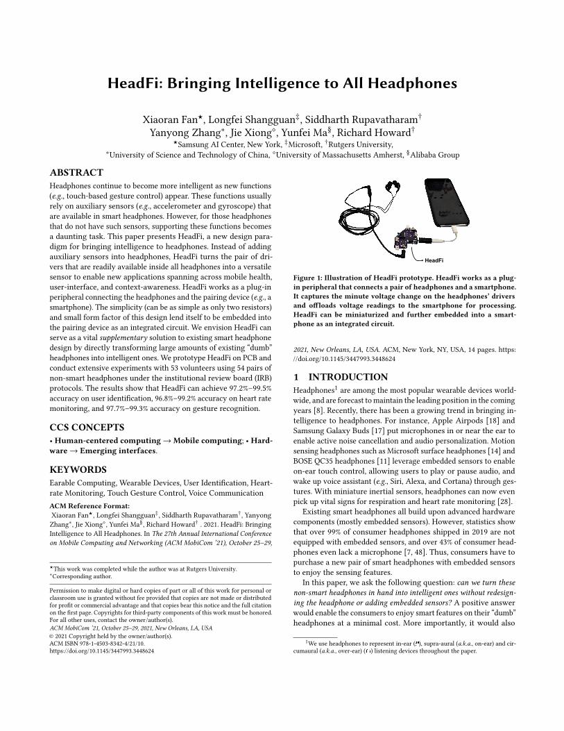
HeadFi: Bringing Intelligence to All Headphones
Xiaoran Fan★, Longfei Shangguan‡, Siddharth Rupavatharam†
Yanyong Zhang∗, Jie Xiong⋄, Yunfei Ma§, Richard Howard†★Samsung AI Center, New York, ‡Microsoft, †Rutgers University,
∗University of Science and Technology of China, ⋄University of Massachusetts Amherst, §Alibaba Group
ABSTRACTHeadphones continue to become more intelligent as new functions(e.g., touch-based gesture control) appear. These functions usuallyrely on auxiliary sensors (e.g., accelerometer and gyroscope) thatare available in smart headphones. However, for those headphonesthat do not have such sensors, supporting these functions becomesa daunting task. This paper presents HeadFi, a new design para-digm for bringing intelligence to headphones. Instead of addingauxiliary sensors into headphones, HeadFi turns the pair of dri-vers that are readily available inside all headphones into a versatilesensor to enable new applications spanning across mobile health,user-interface, and context-awareness. HeadFi works as a plug-inperipheral connecting the headphones and the pairing device (e.g., asmartphone). The simplicity (can be as simple as only two resistors)and small form factor of this design lend itself to be embedded intothe pairing device as an integrated circuit. We envision HeadFi canserve as a vital supplementary solution to existing smart headphonedesign by directly transforming large amounts of existing “dumb”headphones into intelligent ones. We prototype HeadFi on PCB andconduct extensive experiments with 53 volunteers using 54 pairs ofnon-smart headphones under the institutional review board (IRB)protocols. The results show that HeadFi can achieve 97.2%–99.5%accuracy on user identification, 96.8%–99.2% accuracy on heart ratemonitoring, and 97.7%–99.3% accuracy on gesture recognition.
CCS CONCEPTS• Human-centered computing→Mobile computing; • Hard-ware→ Emerging interfaces.
KEYWORDSEarable Computing, Wearable Devices, User Identification, Heart-rate Monitoring, Touch Gesture Control, Voice CommunicationACM Reference Format:Xiaoran Fan★, Longfei Shangguan‡, Siddharth Rupavatharam†, YanyongZhang∗, Jie Xiong⋄, Yunfei Ma§, Richard Howard† . 2021. HeadFi: BringingIntelligence to All Headphones. In The 27th Annual International Conferenceon Mobile Computing and Networking (ACM MobiCom ’21), October 25–29,
★This work was completed while the author was at Rutgers University.∗Corresponding author.
Permission to make digital or hard copies of part or all of this work for personal orclassroom use is granted without fee provided that copies are not made or distributedfor profit or commercial advantage and that copies bear this notice and the full citationon the first page. Copyrights for third-party components of this work must be honored.For all other uses, contact the owner/author(s).ACM MobiCom ’21, October 25–29, 2021, New Orleans, LA, USA© 2021 Copyright held by the owner/author(s).ACM ISBN 978-1-4503-8342-4/21/10.https://doi.org/10.1145/3447993.3448624
HeadFi
Figure 1: Illustration of HeadFi prototype. HeadFi works as a plug-in peripheral that connects a pair of headphones and a smartphone.It captures the minute voltage change on the headphones’ driversand offloads voltage readings to the smartphone for processing.HeadFi can be miniaturized and further embedded into a smart-phone as an integrated circuit.
2021, New Orleans, LA, USA. ACM, New York, NY, USA, 14 pages. https://doi.org/10.1145/3447993.3448624
1 INTRODUCTIONHeadphones1 are among the most popular wearable devices world-wide, and are forecast tomaintain the leading position in the comingyears [8]. Recently, there has been a growing trend in bringing in-telligence to headphones. For instance, Apple Airpods [18] andSamsung Galaxy Buds [17] put microphones in or near the ear toenable active noise cancellation and audio personalization. Motionsensing headphones such as Microsoft surface headphones [14] andBOSE QC35 headphones [11] leverage embedded sensors to enableon-ear touch control, allowing users to play or pause audio, andwake up voice assistant (e.g., Siri, Alexa, and Cortana) through ges-tures. With miniature inertial sensors, headphones can now evenpick up vital signs for respiration and heart rate monitoring [28].
Existing smart headphones all build upon advanced hardwarecomponents (mostly embedded sensors). However, statistics showthat over 99% of consumer headphones shipped in 2019 are notequipped with embedded sensors, and over 43% of consumer head-phones even lack a microphone [7, 48]. Thus, consumers have topurchase a new pair of smart headphones with embedded sensorsto enjoy the sensing features.
In this paper, we ask the following question: can we turn thesenon-smart headphones in hand into intelligent ones without redesign-ing the headphone or adding embedded sensors? A positive answerwould enable the consumers to enjoy smart features on their “dumb”headphones at a minimal cost. More importantly, it would also
1We use headphones to represent in-ear ( ), supra-aural (a.k.a., on-ear) and cir-cumaural (a.k.a., over-ear) ( ) listening devices throughout the paper.
ACM MobiCom ’21, October 25–29, 2021, New Orleans, LA, USA X. Fan, L. Shangguan, S. Rupavatharam, Y. Zhang, J. Xiong, Y. Ma, and R. Howard
pave the way for realizing earable intelligence at an unprecedentedscale by transforming the large amount of existing non-smart head-phones into intelligent ones.
We try to answer this question by presenting the design andimplementation of HeadFi—a low-power and low-cost peripheralthat can be conveniently plugged into a device (such as one’s smart-phone) to enable a multitude of smart functionalities on non-smartheadphones. Our solution serves as an alternative approach to pro-viding smart features to headphone users. HeadFi differs from theexisting smart headphone design in the following two key aspects.Firstly, it uses the headphones, in particular the pair of drivers2 al-ready inside a headphone, as a versatile sensor as opposed to addingauxiliary sensors to enable smart features. Secondly, it serves asa plug-in peripheral, connecting the headphones and the pairingdevice (e.g., a smartphone) in a non-intrusive manner.
HeadFi leverages the coupling effect between the headphonesand the surroundings to enable new functionalities. For example,when a user wears a pair of headphones, the headphones, ear canal,and eardrum would couple together to form a semi-hermetic spacethat is extremely sensitive to pressure changes. A pressure changecan be induced externally by a vibration of the headphones causedby a gentle touch. Similarly, internal physiological activities such asheartbeats cause repetitive deformation of blood vessels in the earcanal, altering the pressure inside the semi-hermetic space. As thevoltage measured at the headphones is affected by these pressurechanges (§2.1), we can thus leverage the voltage variations to detectthe external and subtle internal physiological changes.
To realize this high-level idea, we need to address both technicaland implementation challenges. From the technical point of view,the primary challenge comes from measuring the minute variationin voltage induced by the pressure change. The voltage measure-ment on the headphones is determined by both the audio inputsignal (e.g., music) and the excitation signal. In practice, however,the excitation signals are weak and can easily be buried in the au-dio input signal that is orders of magnitude stronger (discussed inSection 2.2). From the usability point of view, our design should notbreak the appearance and the internal structure of the headphones.Besides, as the headphones are usually driven by mobile devices,our design should also be low power, incurring zero or negligiblepower consumption.
To address these challenges, we are inspired by a null measure-ment circuit design—Wheatstone bridge. Originally Wheatstonebridge was used to measure an unknown resistance by balancingthe two arms of the bridge. In HeadFi, we re-purpose the Wheat-stone bridge to cancel the strong interference of the audio inputsignals to measure the subtle variations in voltage caused by ex-citation signals. Specifically, the left and right two drivers of theheadphones are connected to the two arms of the bridge using theheadphones’ stereo jacket. Once the bridge is balanced, its outputvoltage does not change with the variation of the audio input signal.On the other hand, the output voltage of this bridge still varies withthe pressure change around the headphones, which is affected bythe excitation signals such as the hand touch and the physiologicalactivities.
2Different from computer hardware drivers, a headphone driver is a capacitiveelectronic component that drives the sound down to the ear canal.
Using Wheatstone bridge to detect subtle excitation signalsprovides multiple advantages over existing high-precision meth-ods [30, 32, 40, 41, 63]. First, it provides a high measurement sen-sitivity as it is purely a passive circuit and thus less affected bythermal noises compared to active circuits. Second, the inherent dif-ferential circuit setup of this bridge cancels the strong audio inputsignals without any overhead. Third, it only consists of two simple,passive resistors. The simplicity of this design makes it easy to beminiaturized and embedded into mobile devices. To summarize,this paper makes the following contributions:• We identify the feasibility of using the drivers already inside head-phones to enable smart features. This idea potentially transformsexisting non-smart headphones into smart ones at an unprece-dented scale.
• Wepropose a simple yet effective circuit design to realize this idea.Our design uses purely passive components and costs extremelylittle (i.e., <50 cents when fabricated at scale). We envision tointegrate it into the pairing device (e.g., a smartphone) in thefuture. Our measurement study shows HeadFi has little impacton sound quality of existing audio outputs (§2.4.3).
• We build a proof-of-concept prototype and conduct comprehen-sive experiments. These experiments involve 53 volunteers and54 pairs of headphones with estimated prices ranging from $2.99to $15,000. We further showcase four types of smart applicationson non-smart headphones: user identification, touch based ges-ture control, physiological sensing, and voice communicationwithout a microphone. We believe the potential of HeadFi is farbeyond these.While the current prototype of HeadFi is for wired headphones,
the design can be easily extended to work with wireless headphonesby putting the miniaturized circuit in between the amplifier andthe Digital-to-analog converter (DAC). The rest of this paper isorganized as follows: Section 2 presents the design and performancevalidation. We showcase four intelligent applications in Section 3−6.We discuss related works in Section 7 and potential improvementin Section 8. Conclusion follows in Section 9.
2 TRANSFORMING HEADPHONES INTOSENSORS
HeadFi employs the pair of drivers inside headphones as versatilesensors to realize the functionalities mentioned above. In essence,speakers and microphones are reciprocal in principle [1]. For head-phones without a built-in microphone, an intuitive solution wouldbe turning the speaker3 into a microphone to capture these exci-tation signals. However, this solution does not work in our casedue to the following two reasons. First, the sensitivity of speaker-converted microphone is inferior to purposely-built microphonesas diaphragms in headphones are well-calibrated for playing soundas opposed to sound recording [50]. Second, the excitation signalsare feeble and will be buried in the music signal that is orders ofmagnitude higher. Instead of converting the speakers into micro-phones, we explore the coupling effect between headphones andthe surrounding environment and design a differential circuit to
3The driver is the key component of a speaker in headphones and therefore driverand speaker are used interchangeably throughout the paper.
HeadFi: Bringing Intelligence to All Headphones ACM MobiCom ’21, October 25–29, 2021, New Orleans, LA, USA
Sound wave (mechanical signal)
Cone
Diaphragm
Magnet
Input sound waves (electronic signal)
Coil
Eheadphones
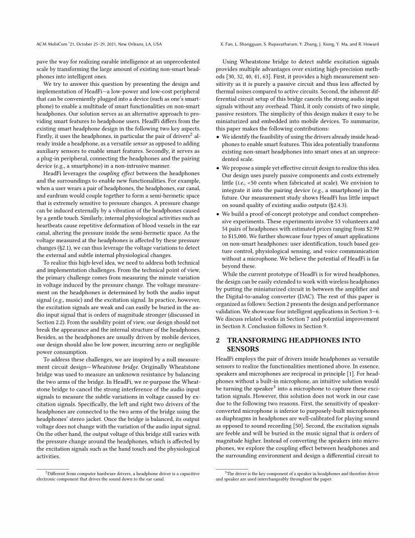
Figure 2: An illustration of headphones’ working principle.
capture the minute voltage variation.
2.1 Modeling the Coupling EffectThe drivers in headphones turn electrical energy into sound byvibrating the air through built-in magnets. We refer to the alter-nating voltage that travels through the headphones’ voice coil as𝐸ℎ𝑒𝑎𝑑𝑝ℎ𝑜𝑛𝑒𝑠 . As shown in Figure 2, the Lorentz force inducted bythe voltage variation pulls the voice coil back and forth, which thendrives the diaphragm to push the air. In this way, the electrical sig-nals are transformed into sound. Note that this process is reciprocal,i.e. the change of air pressure around the diaphragm of headphonesalso alters 𝐸ℎ𝑒𝑎𝑑𝑝ℎ𝑜𝑛𝑒𝑠 .
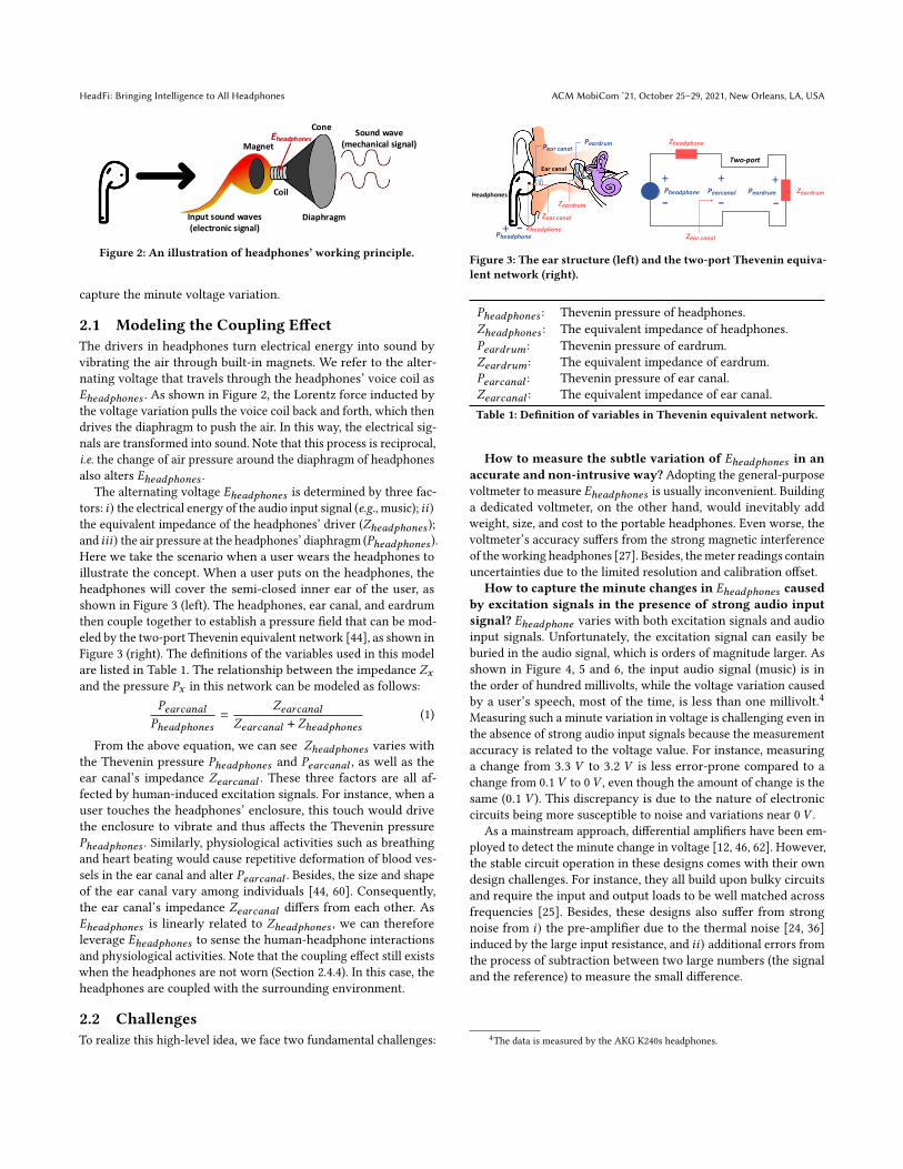
The alternating voltage 𝐸ℎ𝑒𝑎𝑑𝑝ℎ𝑜𝑛𝑒𝑠 is determined by three fac-tors: 𝑖) the electrical energy of the audio input signal (e.g., music); 𝑖𝑖)the equivalent impedance of the headphones’ driver (𝑍ℎ𝑒𝑎𝑑𝑝ℎ𝑜𝑛𝑒𝑠 );and 𝑖𝑖𝑖) the air pressure at the headphones’ diaphragm (𝑃ℎ𝑒𝑎𝑑𝑝ℎ𝑜𝑛𝑒𝑠 ).Here we take the scenario when a user wears the headphones toillustrate the concept. When a user puts on the headphones, theheadphones will cover the semi-closed inner ear of the user, asshown in Figure 3 (left). The headphones, ear canal, and eardrumthen couple together to establish a pressure field that can be mod-eled by the two-port Thevenin equivalent network [44], as shown inFigure 3 (right). The definitions of the variables used in this modelare listed in Table 1. The relationship between the impedance 𝑍𝑥and the pressure 𝑃𝑥 in this network can be modeled as follows:
𝑃𝑒𝑎𝑟𝑐𝑎𝑛𝑎𝑙
𝑃ℎ𝑒𝑎𝑑𝑝ℎ𝑜𝑛𝑒𝑠=
𝑍𝑒𝑎𝑟𝑐𝑎𝑛𝑎𝑙
𝑍𝑒𝑎𝑟𝑐𝑎𝑛𝑎𝑙 + 𝑍ℎ𝑒𝑎𝑑𝑝ℎ𝑜𝑛𝑒𝑠(1)
From the above equation, we can see 𝑍ℎ𝑒𝑎𝑑𝑝ℎ𝑜𝑛𝑒𝑠 varies withthe Thevenin pressure 𝑃ℎ𝑒𝑎𝑑𝑝ℎ𝑜𝑛𝑒𝑠 and 𝑃𝑒𝑎𝑟𝑐𝑎𝑛𝑎𝑙 , as well as theear canal’s impedance 𝑍𝑒𝑎𝑟𝑐𝑎𝑛𝑎𝑙 . These three factors are all af-fected by human-induced excitation signals. For instance, when auser touches the headphones’ enclosure, this touch would drivethe enclosure to vibrate and thus affects the Thevenin pressure𝑃ℎ𝑒𝑎𝑑𝑝ℎ𝑜𝑛𝑒𝑠 . Similarly, physiological activities such as breathingand heart beating would cause repetitive deformation of blood ves-sels in the ear canal and alter 𝑃𝑒𝑎𝑟𝑐𝑎𝑛𝑎𝑙 . Besides, the size and shapeof the ear canal vary among individuals [44, 60]. Consequently,the ear canal’s impedance 𝑍𝑒𝑎𝑟𝑐𝑎𝑛𝑎𝑙 differs from each other. As𝐸ℎ𝑒𝑎𝑑𝑝ℎ𝑜𝑛𝑒𝑠 is linearly related to 𝑍ℎ𝑒𝑎𝑑𝑝ℎ𝑜𝑛𝑒𝑠 , we can thereforeleverage 𝐸ℎ𝑒𝑎𝑑𝑝ℎ𝑜𝑛𝑒𝑠 to sense the human-headphone interactionsand physiological activities. Note that the coupling effect still existswhen the headphones are not worn (Section 2.4.4). In this case, theheadphones are coupled with the surrounding environment.
2.2 ChallengesTo realize this high-level idea, we face two fundamental challenges:
Headphones
Ear canal
Zeardrum
Zheadphone
Zear canal
Zheadphone
++
- -
Zear canal
+
-+ -
Pear canalPeardrum
Pearcanal PeardrumPheadphone
Two-port
Zeardrum
Pheadphone
Figure 3: The ear structure (left) and the two-port Thevenin equiva-lent network (right).
𝑃ℎ𝑒𝑎𝑑𝑝ℎ𝑜𝑛𝑒𝑠 : Thevenin pressure of headphones.𝑍ℎ𝑒𝑎𝑑𝑝ℎ𝑜𝑛𝑒𝑠 : The equivalent impedance of headphones.𝑃𝑒𝑎𝑟𝑑𝑟𝑢𝑚 : Thevenin pressure of eardrum.𝑍𝑒𝑎𝑟𝑑𝑟𝑢𝑚 : The equivalent impedance of eardrum.𝑃𝑒𝑎𝑟𝑐𝑎𝑛𝑎𝑙 : Thevenin pressure of ear canal.𝑍𝑒𝑎𝑟𝑐𝑎𝑛𝑎𝑙 : The equivalent impedance of ear canal.Table 1: Definition of variables in Thevenin equivalent network.
How to measure the subtle variation of 𝐸ℎ𝑒𝑎𝑑𝑝ℎ𝑜𝑛𝑒𝑠 in anaccurate and non-intrusive way? Adopting the general-purposevoltmeter to measure 𝐸ℎ𝑒𝑎𝑑𝑝ℎ𝑜𝑛𝑒𝑠 is usually inconvenient. Buildinga dedicated voltmeter, on the other hand, would inevitably addweight, size, and cost to the portable headphones. Even worse, thevoltmeter’s accuracy suffers from the strong magnetic interferenceof theworking headphones [27]. Besides, themeter readings containuncertainties due to the limited resolution and calibration offset.
How to capture the minute changes in 𝐸ℎ𝑒𝑎𝑑𝑝ℎ𝑜𝑛𝑒𝑠 causedby excitation signals in the presence of strong audio inputsignal? 𝐸ℎ𝑒𝑎𝑑𝑝ℎ𝑜𝑛𝑒 varies with both excitation signals and audioinput signals. Unfortunately, the excitation signal can easily beburied in the audio signal, which is orders of magnitude larger. Asshown in Figure 4, 5 and 6, the input audio signal (music) is inthe order of hundred millivolts, while the voltage variation causedby a user’s speech, most of the time, is less than one millivolt.4Measuring such a minute variation in voltage is challenging even inthe absence of strong audio input signals because the measurementaccuracy is related to the voltage value. For instance, measuringa change from 3.3 𝑉 to 3.2 𝑉 is less error-prone compared to achange from 0.1𝑉 to 0𝑉 , even though the amount of change is thesame (0.1 𝑉 ). This discrepancy is due to the nature of electroniccircuits being more susceptible to noise and variations near 0 𝑉 .
As a mainstream approach, differential amplifiers have been em-ployed to detect the minute change in voltage [12, 46, 62]. However,the stable circuit operation in these designs comes with their owndesign challenges. For instance, they all build upon bulky circuitsand require the input and output loads to be well matched acrossfrequencies [25]. Besides, these designs also suffer from strongnoise from 𝑖) the pre-amplifier due to the thermal noise [24, 36]induced by the large input resistance, and 𝑖𝑖) additional errors fromthe process of subtraction between two large numbers (the signaland the reference) to measure the small difference.
4The data is measured by the AKG K240s headphones.
ACM MobiCom ’21, October 25–29, 2021, New Orleans, LA, USA X. Fan, L. Shangguan, S. Rupavatharam, Y. Zhang, J. Xiong, Y. Ma, and R. Howard
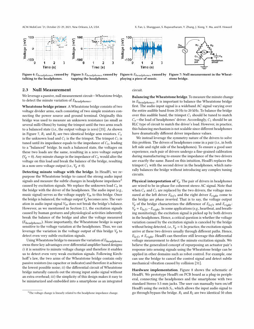
Figure 4: 𝐸ℎ𝑒𝑎𝑑𝑝ℎ𝑜𝑛𝑒𝑠 caused bytalking to the headphones.
Figure 5: 𝐸ℎ𝑒𝑎𝑑𝑝ℎ𝑜𝑛𝑒𝑠 caused bytapping the headphones.
Figure 6: 𝐸ℎ𝑒𝑎𝑑𝑝ℎ𝑜𝑛𝑒𝑠 caused byplaying a piece of music.
Trimpot
Headphonedriver
R1 R2
C1 Cx
Vg
Vin(audio)
Figure 7: Null measurement in the Wheat-stone bridge.
2.3 Null MeasurementWe leverage a passive, null measurement circuit—Wheatstone bridge,to detect the minute variation of 𝐸ℎ𝑒𝑎𝑑𝑝ℎ𝑜𝑛𝑒𝑠 .
Wheatstone bridge primer. AWheatstone bridge consists of twovoltage divider arms, each consisting of two simple resistors con-necting the power source and ground terminal. Originally thisbridge was used to measure an unknown resistance (as small asseveral milli-Ohms) by tuning the trimpot until the two arms reachto a balanced state (i.e., the output voltage is zero) [35]. As shownin Figure 7, 𝑅1 and 𝑅2 are two identical bridge arm resistors. 𝐶𝑥is the unknown load and 𝐶1 is the the trimpot. The trimpot 𝐶1 istuned until its impedance equals to the impedance of 𝐶𝑥 , leadingto a “balanced” bridge. In such a balanced state, the voltages onthese two loads are the same, resulting in a zero voltage output(𝑉𝑔 = 0). Any minute change in the impedance of𝐶𝑥 would alter thevoltage on this load and break the balance of the bridge, resultingin a non-zero voltage output (i.e., 𝑉𝑔 ≠ 0).
Detecting minute voltage with the bridge. In HeadFi, we re-purpose the Wheatstone bridge to cancel the strong audio inputsignals and measure the subtle changes in headphone impedance5caused by excitation signals. We replace the unknown load 𝐶𝑥 inthe bridge with the driver of the headphones. The audio input (e.g.,music signal) serves as the voltage supply 𝑉𝑖𝑛 to this bridge. Oncethe bridge is balanced, the voltage output𝑉𝑔 becomes zero. The vari-ation in audio input signal 𝑉𝑖𝑛 does not break the bridge’s balance.However, as we mentioned in Section 2.1, the excitation signalscaused by human gestures and physiological activities inherentlybreak the balance of the bridge and alter the voltage measured(𝐸ℎ𝑒𝑎𝑑𝑝ℎ𝑜𝑛𝑒𝑠 ). More importantly, the Wheatstone bridge is supersensitive to the voltage variation at the headphones. Thus, we canleverage the variation in the voltage output of this bridge 𝑉𝑔 todetect even very subtle excitation signals.
UsingWheatstone bridge tomeasure the variation of𝐸ℎ𝑒𝑎𝑑𝑝ℎ𝑜𝑛𝑒𝑠owns three key advantages over differential amplifier based designs:𝑖) it is sensitive to minute voltage change and therefore it enablesus to detect even very weak excitation signals. Following Kirch-hoff’s law, the two arms of the Wheatstone bridge contain onlypassive resistors (no capacitor or indicator) and therefore it achievesthe lowest possible noise; 𝑖𝑖) the differential circuit of Wheatstonebridge naturally cancels out the strong input audio signal withoutan extra overhead; 𝑖𝑖𝑖) the simplicity of this design makes it easy tobe miniaturized and embedded into a smartphone as an integrated
5The voltage change is linearly related to the headphone impedance change.
circuit.
Balancing theWheatstone bridge. Tomeasure theminute changein 𝐸ℎ𝑒𝑎𝑑𝑝ℎ𝑜𝑛𝑒𝑠 , it is important to balance the Wheatstone bridgefirst. The audio input signal is a wideband AC signal varying overthe entire audible band from 20 Hz to 20 kHz. To balance the bridgeover this audible band, the trimpot 𝐶1 should be tuned to match𝐶𝑥—the load of headphones’ driver. Accordingly, 𝐶1 should be anRLC type of circuit to match the driver’s load. However, in practice,this balancing mechanism is not scalable since different headphoneshave dramatically different driver impedance values.
We instead leverage the symmetry nature of the drivers to solvethis problem. The drivers of headphones come in a pair (i.e., in bothleft side and right side of the headphones). To ensure a good userexperience, each pair of drivers undergo a fine-grained calibrationduring manufacturing to ensure the impedance of the two driversare exactly the same. Based on this intuition, HeadFi replaces thetrimpot 𝐶1 with the second driver in the headphones, which natu-rally balances the bridge without introducing any complex tuningcircuits.
Physical interpretation of𝑉𝑔 . The pair of drivers in headphonesare wired to be in-phase for coherent stereo AC signal. Note thatwhen 𝐶𝑥 and 𝐶1 are replaced by the two drivers, the voltage mea-sured at the left driver 𝐸𝑙𝑒 𝑓 𝑡 and the right driver 𝐸𝑟𝑖𝑔ℎ𝑡 come tothe bridge are phase inverted. That is to say, the voltage output𝑉𝑔 of the bridge characterizes the difference of 𝐸𝑙𝑒 𝑓 𝑡 and 𝐸𝑟𝑖𝑔ℎ𝑡 :𝑉𝑔 = 𝐸𝑙𝑒 𝑓 𝑡 −𝐸𝑟𝑖𝑔ℎ𝑡 . In some applications (e.g., heartbeat, and breath-ing monitoring), the excitation signal is picked up by both driversin the headphones. Hence, a critical question is whether the voltagevariation caused by the excitation signals is canceled by the bridgewithout being detected, i.e.,𝑉𝑔 = 0. In practice, the excitation signalsarrive at these two drivers usually through different paths. Hence,𝐸𝑙𝑒 𝑓 𝑡 ≠ 𝐸𝑟𝑖𝑔ℎ𝑡 . HeadFi can therefore still leverage this differentialvoltage measurement to detect the minute excitation signals. Webelieve the generalized concept of repurposing an actuator pair’sresponse into sensing signals using the Wheatstone bridge can beapplied in other domains such as robot control. For example, onecan use the bridge to cancel the control signal and detect subtlemechanical vibration caused by collision [31].
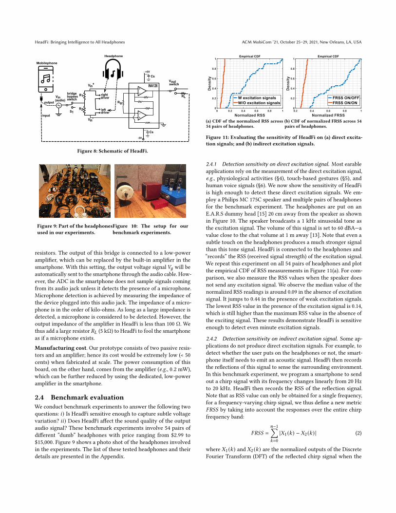
Hardware implementation. Figure 8 shows the schematic ofHeadFi. We prototype HeadFi on PCB board as a plug-in periph-eral, connecting the headphones and the smartphone with twostandard Stereo 3.5 mm jacks. The user can manually turn on/offHeadFi using the switch 𝑆1, which allows the input audio signal togo through/bypass the bridge. 𝑅1 and 𝑅2 are two identical 50 ohm
HeadFi: Bringing Intelligence to All Headphones ACM MobiCom ’21, October 25–29, 2021, New Orleans, LA, USA
RL
Vin+
Voutswitch
Vin(audio)
-5V
Rg
INA126
Vin-
R1
R2
+5V
Cs
Cs
driverright
driverleft
bridge
switchbypass
Mobilephone
Headphone
output
inputS1
Figure 8: Schematic of HeadFi.
Figure 9: Part of the headphonesused in our experiments.
Figure 10: The setup for ourbenchmark experiments.
resistors. The output of this bridge is connected to a low-poweramplifier, which can be replaced by the built-in amplifier in thesmartphone. With this setting, the output voltage signal 𝑉𝑔 will beautomatically sent to the smartphone through the audio cable. How-ever, the ADC in the smartphone does not sample signals comingfrom its audio jack unless it detects the presence of a microphone.Microphone detection is achieved by measuring the impedance ofthe device plugged into this audio jack. The impedance of a micro-phone is in the order of kilo-ohms. As long as a large impedance isdetected, a microphone is considered to be detected. However, theoutput impedance of the amplifier in HeadFi is less than 100 Ω. Wethus add a large resistor 𝑅𝐿 (5 kΩ) to HeadFi to fool the smartphoneas if a microphone exists.
Manufacturing cost. Our prototype consists of two passive resis-tors and an amplifier; hence its cost would be extremely low (< 50cents) when fabricated at scale. The power consumption of thisboard, on the other hand, comes from the amplifier (e.g., 0.2 mW),which can be further reduced by using the dedicated, low-poweramplifier in the smartphone.
2.4 Benchmark evaluationWe conduct benchmark experiments to answer the following twoquestions: 𝑖) Is HeadFi sensitive enough to capture subtle voltagevariation? 𝑖𝑖) Does HeadFi affect the sound quality of the outputaudio signal? These benchmark experiments involve 54 pairs ofdifferent “dumb” headphones with price ranging from $2.99 to$15,000. Figure 9 shows a photo shot of the headphones involvedin the experiments. The list of these tested headphones and theirdetails are presented in the Appendix.
(a) CDF of the normalized RSS across54 pairs of headphones.
(b) CDF of normalized FRSS across 54pairs of headphones.
Figure 11: Evaluating the sensitivity of HeadFi on (a) direct excita-tion signals; and (b) indirect excitation signals.
2.4.1 Detection sensitivity on direct excitation signal. Most earableapplications rely on the measurement of the direct excitation signal,e.g., physiological activities (§4), touch-based gestures (§5), andhuman voice signals (§6). We now show the sensitivity of HeadFiis high enough to detect these direct excitation signals. We em-ploy a Philips MC 175C speaker and multiple pairs of headphonesfor the benchmark experiment. The headphones are put on anE.A.R.S dummy head [15] 20 cm away from the speaker as shownin Figure 10. The speaker broadcasts a 1 kHz sinusoidal tone asthe excitation signal. The volume of this signal is set to 60 dBA—avalue close to the chat volume at 1 m away [13]. Note that even asubtle touch on the headphones produces a much stronger signalthan this tone signal. HeadFi is connected to the headphones and“records” the RSS (received signal strength) of the excitation signal.We repeat this experiment on all 54 pairs of headphones and plotthe empirical CDF of RSS measurements in Figure 11(a). For com-parison, we also measure the RSS values when the speaker doesnot send any excitation signal. We observe the median value of thenormalized RSS readings is around 0.09 in the absence of excitationsignal. It jumps to 0.44 in the presence of weak excitation signals.The lowest RSS value in the presence of the excitation signal is 0.14,which is still higher than the maximum RSS value in the absence ofthe exciting signal. These results demonstrate HeadFi is sensitiveenough to detect even minute excitation signals.
2.4.2 Detection sensitivity on indirect excitation signal. Some ap-plications do not produce direct excitation signals. For example, todetect whether the user puts on the headphones or not, the smart-phone itself needs to emit an acoustic signal. HeadFi then recordsthe reflections of this signal to sense the surrounding environment.In this benchmark experiment, we program a smartphone to sendout a chirp signal with its frequency changes linearly from 20 Hzto 20 kHz. HeadFi then records the RSS of the reflection signal.Note that as RSS value can only be obtained for a single frequency,for a frequency-varying chirp signal, we thus define a new metric𝐹𝑅𝑆𝑆 by taking into account the responses over the entire chirpfrequency band:
𝐹𝑅𝑆𝑆 =
𝑛−1∑𝑘=0
|𝑋1 (𝑘) − 𝑋2 (𝑘) | (2)
where 𝑋1 (𝑘) and 𝑋2 (𝑘) are the normalized outputs of the DiscreteFourier Transform (DFT) of the reflected chirp signal when the
ACM MobiCom ’21, October 25–29, 2021, New Orleans, LA, USA X. Fan, L. Shangguan, S. Rupavatharam, Y. Zhang, J. Xiong, Y. Ma, and R. Howard
- W HeadFi
- W/O HeadFi
- W HeadFi
- W/O HeadFi
Sennheiser HD600
Mackie MC150
(a) The impact of HeadFi on head-phones’ frequency response (FR).
W/O headFi
W headFi
(b) A snapshot of the cumulative spec-tral decay (CSD).
Figure 12: The impact ofHeadFi onheadphones. (a) The FRof ahigh-(Sennheiser HD600, $399.95) and low-quality (MackieMC150, $49.0)headphones in the presence and absence of HeadFi, respectively. (b)A CSD snapshot of Mackie MC150.
headphones are ON and OFF the dummy head respectively. 𝑛 is thenumber of DFT frequency bins.
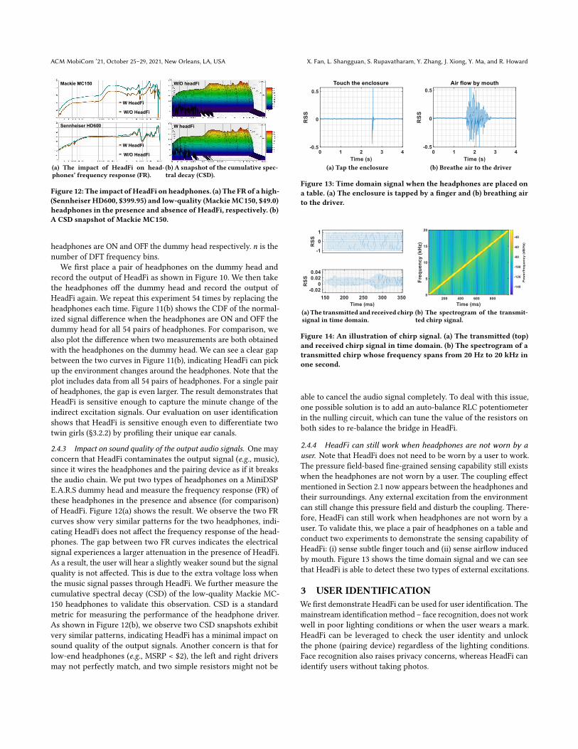
We first place a pair of headphones on the dummy head andrecord the output of HeadFi as shown in Figure 10. We then takethe headphones off the dummy head and record the output ofHeadFi again. We repeat this experiment 54 times by replacing theheadphones each time. Figure 11(b) shows the CDF of the normal-ized signal difference when the headphones are ON and OFF thedummy head for all 54 pairs of headphones. For comparison, wealso plot the difference when two measurements are both obtainedwith the headphones on the dummy head. We can see a clear gapbetween the two curves in Figure 11(b), indicating HeadFi can pickup the environment changes around the headphones. Note that theplot includes data from all 54 pairs of headphones. For a single pairof headphones, the gap is even larger. The result demonstrates thatHeadFi is sensitive enough to capture the minute change of theindirect excitation signals. Our evaluation on user identificationshows that HeadFi is sensitive enough even to differentiate twotwin girls (§3.2.2) by profiling their unique ear canals.
2.4.3 Impact on sound quality of the output audio signals. One mayconcern that HeadFi contaminates the output signal (e.g., music),since it wires the headphones and the pairing device as if it breaksthe audio chain. We put two types of headphones on a MiniDSPE.A.R.S dummy head and measure the frequency response (FR) ofthese headphones in the presence and absence (for comparison)of HeadFi. Figure 12(a) shows the result. We observe the two FRcurves show very similar patterns for the two headphones, indi-cating HeadFi does not affect the frequency response of the head-phones. The gap between two FR curves indicates the electricalsignal experiences a larger attenuation in the presence of HeadFi.As a result, the user will hear a slightly weaker sound but the signalquality is not affected. This is due to the extra voltage loss whenthe music signal passes through HeadFi. We further measure thecumulative spectral decay (CSD) of the low-quality Mackie MC-150 headphones to validate this observation. CSD is a standardmetric for measuring the performance of the headphone driver.As shown in Figure 12(b), we observe two CSD snapshots exhibitvery similar patterns, indicating HeadFi has a minimal impact onsound quality of the output signals. Another concern is that forlow-end headphones (e.g., MSRP < $2), the left and right driversmay not perfectly match, and two simple resistors might not be
(a) Tap the enclosure (b) Breathe air to the driver
Figure 13: Time domain signal when the headphones are placed ona table. (a) The enclosure is tapped by a finger and (b) breathing airto the driver.
(a) The transmitted and received chirpsignal in time domain.
(b) The spectrogram of the transmit-ted chirp signal.
Figure 14: An illustration of chirp signal. (a) The transmitted (top)and received chirp signal in time domain. (b) The spectrogram of atransmitted chirp whose frequency spans from 20 Hz to 20 kHz inone second.
able to cancel the audio signal completely. To deal with this issue,one possible solution is to add an auto-balance RLC potentiometerin the nulling circuit, which can tune the value of the resistors onboth sides to re-balance the bridge in HeadFi.
2.4.4 HeadFi can still work when headphones are not worn by auser. Note that HeadFi does not need to be worn by a user to work.The pressure field-based fine-grained sensing capability still existswhen the headphones are not worn by a user. The coupling effectmentioned in Section 2.1 now appears between the headphones andtheir surroundings. Any external excitation from the environmentcan still change this pressure field and disturb the coupling. There-fore, HeadFi can still work when headphones are not worn by auser. To validate this, we place a pair of headphones on a table andconduct two experiments to demonstrate the sensing capability ofHeadFi: (i) sense subtle finger touch and (ii) sense airflow inducedby mouth. Figure 13 shows the time domain signal and we can seethat HeadFi is able to detect these two types of external excitations.
3 USER IDENTIFICATIONWe first demonstrate HeadFi can be used for user identification. Themainstream identification method – face recognition, does not workwell in poor lighting conditions or when the user wears a mark.HeadFi can be leveraged to check the user identity and unlockthe phone (pairing device) regardless of the lighting conditions.Face recognition also raises privacy concerns, whereas HeadFi canidentify users without taking photos.
HeadFi: Bringing Intelligence to All Headphones ACM MobiCom ’21, October 25–29, 2021, New Orleans, LA, USA
(a) iHip Mr Bud ($ 3.6) (b) Beyerdynamic T1 ($ 999)
Figure 15: Channel response of three persons characterized by (a)low-end and (b) high-end headphones.
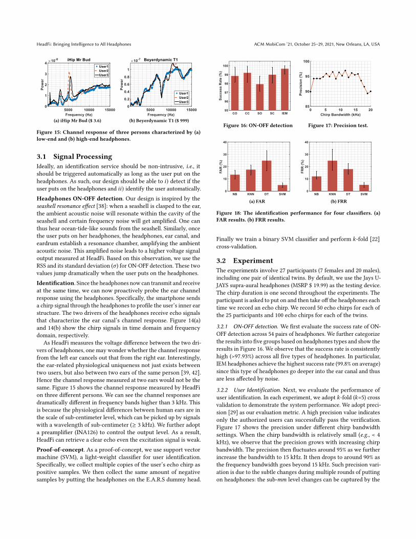
3.1 Signal ProcessingIdeally, an identification service should be non-intrusive, i.e., itshould be triggered automatically as long as the user put on theheadphones. As such, our design should be able to 𝑖) detect if theuser puts on the headphones and 𝑖𝑖) identify the user automatically.Headphones ON-OFF detection. Our design is inspired by theseashell resonance effect [38]: when a seashell is clasped to the ear,the ambient acoustic noise will resonate within the cavity of theseashell and certain frequency noise will get amplified. One canthus hear ocean-tide-like sounds from the seashell. Similarly, oncethe user puts on her headphones, the headphones, ear canal, andeardrum establish a resonance chamber, amplifying the ambientacoustic noise. This amplified noise leads to a higher voltage signaloutput measured at HeadFi. Based on this observation, we use theRSS and its standard deviation (𝜎) for ON-OFF detection. These twovalues jump dramatically when the user puts on the headphones.Identification. Since the headphones now can transmit and receiveat the same time, we can now proactively probe the ear channelresponse using the headphones. Specifically, the smartphone sendsa chirp signal through the headphones to profile the user’s inner earstructure. The two drivers of the headphones receive echo signalsthat characterize the ear canal’s channel response. Figure 14(a)and 14(b) show the chirp signals in time domain and frequencydomain, respectively.
As HeadFi measures the voltage difference between the two dri-vers of headphones, one may wonder whether the channel responsefrom the left ear cancels out that from the right ear. Interestingly,the ear-related physiological uniqueness not just exists betweentwo users, but also between two ears of the same person [39, 42].Hence the channel response measured at two ears would not be thesame. Figure 15 shows the channel response measured by HeadFion three different persons. We can see the channel responses aredramatically different in frequency bands higher than 3 kHz. Thisis because the physiological differences between human ears are inthe scale of sub-centimeter level, which can be picked up by signalswith a wavelength of sub-centimeter (≥ 3 kHz). We further adopta preamplifier (INA126) to control the output level. As a result,HeadFi can retrieve a clear echo even the excitation signal is weak.Proof-of-concept. As a proof-of-concept, we use support vectormachine (SVM), a light-weight classifier for user identification.Specifically, we collect multiple copies of the user’s echo chirp aspositive samples. We then collect the same amount of negativesamples by putting the headphones on the E.A.R.S dummy head.
Figure 16: ON-OFF detection Figure 17: Precision test.
(a) FAR (b) FRR
Figure 18: The identification performance for four classifiers. (a)FAR results. (b) FRR results.
Finally we train a binary SVM classifier and perform 𝑘-fold [22]cross-validation.
3.2 ExperimentThe experiments involve 27 participants (7 females and 20 males),including one pair of identical twins. By default, we use the Jays U-JAYS supra-aural headphones (MSRP $ 19.99) as the testing device.The chirp duration is one second throughout the experiments. Theparticipant is asked to put on and then take off the headphones eachtime we record an echo chirp. We record 50 echo chirps for each ofthe 25 participants and 100 echo chirps for each of the twins.
3.2.1 ON-OFF detection. We first evaluate the success rate of ON-OFF detection across 54 pairs of headphones. We further categorizethe results into five groups based on headphones types and show theresults in Figure 16. We observe that the success rate is consistentlyhigh (>97.93%) across all five types of headphones. In particular,IEM headphones achieve the highest success rate (99.8% on average)since this type of headphones go deeper into the ear canal and thusare less affected by noise.
3.2.2 User Identification. Next, we evaluate the performance ofuser identification. In each experiment, we adopt 𝑘-fold (𝑘=5) crossvalidation to demonstrate the system performance. We adopt preci-sion [29] as our evaluation metric. A high precision value indicatesonly the authorized users can successfully pass the verification.Figure 17 shows the precision under different chirp bandwidthsettings. When the chirp bandwidth is relatively small (e.g., < 4kHz), we observe that the precision grows with increasing chirpbandwidth. The precision then fluctuates around 95% as we furtherincrease the bandwidth to 15 kHz. It then drops to around 90% asthe frequency bandwidth goes beyond 15 kHz. Such precision vari-ation is due to the subtle changes during multiple rounds of puttingon headphones: the sub-𝑚𝑚 level changes can be captured by the
ACM MobiCom ’21, October 25–29, 2021, New Orleans, LA, USA X. Fan, L. Shangguan, S. Rupavatharam, Y. Zhang, J. Xiong, Y. Ma, and R. Howard
PredictionUser One User Two Total
Ground-truth User One 36, 018(94.8%) 1, 982(5.2%) 38, 000User Two 1, 831(4.8%) 36, 169(95.2%) 38, 000
Table 2: Confusion matrix for twin girls. The results are presentedusing 𝑘-fold cross validation.
Status Sitting still Moving head Eating Walking
FRR (%) 3.64 4.75 5.15 8.75
Table 3: Impact of human motions.
high-frequency (higher than 15 kHz) signal, which disturbs theuser identification. Suggested by this study, we employ a frequencyband from 100 Hz to 10 kHz as the default chirp bandwidth. Weexclude the frequency band below 100 Hz because most mechanicalmovement-induced noise is in this frequency range.
Impact of different classifiers. Next, we evaluate the identifi-cation performance with four classifiers, Naive Bayesian (NB), 𝑘-nearest neighbors (KNN), decision tree (DT), and SVM. We investi-gate and report the false acceptance rate (FAR) and false rejectionrate (FRR). As shown in Figure 18(a) and 18(b), SVM achieves thebest performance for both FAR and FRR. We envision more ad-vanced learning techniques such as DNN can be applied to furtherimprove the identification performance.
Differentiating twins. We further conduct user identification ex-periment on two 26-year old identical twin girls. Identifying twinsis challenging because they share very similar physiological fea-tures. However, as suggested by the confusion matrix in Table 2,the identification performance for twins is comparable (95% successrate) to other individuals. Note we collected 100 echo chirps for eachindividual of the twins. Therefore we performed a total of 38000classification tests for each individual in the 𝑘-fold cross-validation.
Impact of humanmotions. We conduct user identification whenthe subject is sitting still, moving her head, eating, and walking.The result is shown in Table 3. We observe that larger body move-ments undermine the user identification performance. In particular,HeadFi achieves the lowest false rejection rate when the subject issitting still. The false rejection rate increases as the user starts tomove, e.g. eating, walking, or moving her head. This is expectedsince the headphones are likely to move with the human motionsand alter the channel response.
Long-term user identification. We further track one volunteerover two months and record the user identification performanceover time. The result is shown in Table 4. We observe that the iden-tification precision decreases gradually from 96.45% to 92.17% overtwo months. We suspect the reason behind this is the physiologicalcharacteristics of this subject change over time. For example, thefluid in the ear can alter the ear canal’s frequency response, whichimpacts the user identification performance [26]. To validate thishypothesis, we conduct user identification after the shower and
Time Reference One Day One Week One Month Two Months
Average Precision (%) 96.45 95.20 94.51 93.26 92.17
Table 4: Identification performance over time.
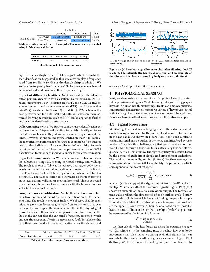
(a) The voltage output before and af-ter filtering.
(b) The ACF plot and time domain in-terference.
Figure 19: (a) heartbeat signal becomes clear after filtering. (b) ACFis adopted to calculate the heartbeat rate (top) and an example oftime domain interference caused by body movements (bottom).
observe a 7% drop in identification accuracy.
4 PHYSIOLOGICAL SENSINGNext, we demonstrate the feasibility of applying HeadFi to detectsubtle physiological signals. Vital physiological sign sensing plays akey role in human health monitoring. HeadFi can empower users tocontinuously and accurately monitor a variety of key physiologicalactivities (e.g., heartbeat rate) using their non-smart headphones.Below we take heartbeat monitoring as an illustrative example.
4.1 Signal ProcessingMonitoring heartbeat is challenging due to the extremely weakexcitation signal induced by the subtle blood vessel deformationin the ear canal. As shown in Figure 19(a) (top), such a minuteexcitation signal can be buried in the noise and interfered by usermotions. To solve this challenge, we first pass the signal outputfrom HeadFi through a low-pass filter with a very low cut-off fre-quency (𝐹𝑐 = 24Hz) to remove the high-frequency noise introducedby the echoes of audio input signals and environment excitations.The result is shown in Figure 19(a) (bottom). We then leverage theauto-correlation function (ACF) to identify the periodicity whichcorresponds to the heartbeat rate:
𝑟𝑥𝑥 (𝑘) =1
𝑁 − 𝑘
𝑁−1−𝑘∑𝑛=0
𝑥 (𝑛)𝑥 (𝑛 + 𝑘) . (3)
where 𝑥 (𝑛) is a copy of the signal output from HeadFi and 𝑘 isthe lag. 𝑁 is the length of the received signals. Figure 19(b) (top)shows an example of the auto-correlation output. The location ofpeak values reflects the time period of one heartbeat cycle. Blindlyenumerating all choice of 𝑘 in hopes of finding the peak is compu-tationally intractable. It may also introduce false positives. We thusset the upper (𝑈 ) and lower (𝐿) bounds of 𝑘 based on the possibleheartbeat rate of human beings (35 - 200 bpm [59]). Our goal canbe represented by the following function:
𝑘★ = argmax𝑘⊆(𝐿,𝑈 )
𝑟𝑥𝑥 (𝑘) . (4)
We then calculate the heartbeat rate using the equation 𝑅𝐵𝑃𝑀 =
60 · 𝐹𝑠𝑘★
, where 𝐹𝑠 is the sampling rate. In reality, however, bodymovements may also introduce strong excitation signals that canoverwhelm the minute heartbeat signals, as shown in Figure 19(b)(bottom). We thus truncate the voltage output from HeadFi into
HeadFi: Bringing Intelligence to All Headphones ACM MobiCom ’21, October 25–29, 2021, New Orleans, LA, USA
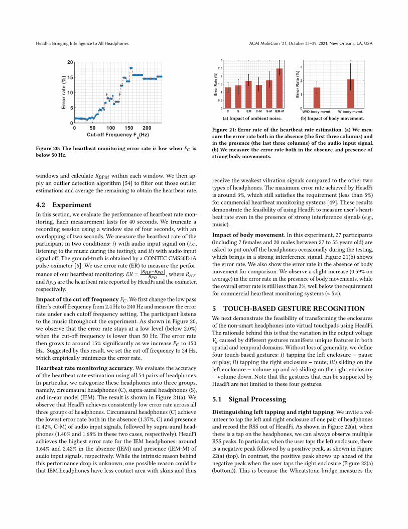
Figure 20: The heartbeat monitoring error rate is low when 𝐹𝐶 isbelow 50 Hz.
windows and calculate 𝑅𝐵𝑃𝑀 within each window. We then ap-ply an outlier detection algorithm [54] to filter out those outlierestimations and average the remaining to obtain the heartbeat rate.
4.2 ExperimentIn this section, we evaluate the performance of heartbeat rate mon-itoring. Each measurement lasts for 40 seconds. We truncate arecording session using a window size of four seconds, with anoverlapping of two seconds. We measure the heartbeat rate of theparticipant in two conditions: 𝑖) with audio input signal on (i.e.,listening to the music during the testing); and 𝑖𝑖) with audio inputsignal off. The ground-truth is obtained by a CONTEC CMS50D1Apulse oximeter [6]. We use error rate (ER) to measure the perfor-mance of our heartbeat monitoring: 𝐸𝑅 =
|𝑅𝐻𝐹−𝑅𝑃𝑂 |𝑅𝑃𝑂
, where 𝑅𝐻𝐹
and 𝑅𝑃𝑂 are the heartbeat rate reported by HeadFi and the oximeter,respectively.
Impact of the cut off frequency 𝐹𝐶 . We first change the low passfilter’s cutoff frequency from 2.4 Hz to 240 Hz and measure the errorrate under each cutoff frequency setting. The participant listensto the music throughout the experiment. As shown in Figure 20,we observe that the error rate stays at a low level (below 2.0%)when the cut-off frequency is lower than 50 Hz. The error ratethen grows to around 15% significantly as we increase 𝐹𝐶 to 150Hz. Suggested by this result, we set the cut-off frequency to 24 Hz,which empirically minimizes the error rate.
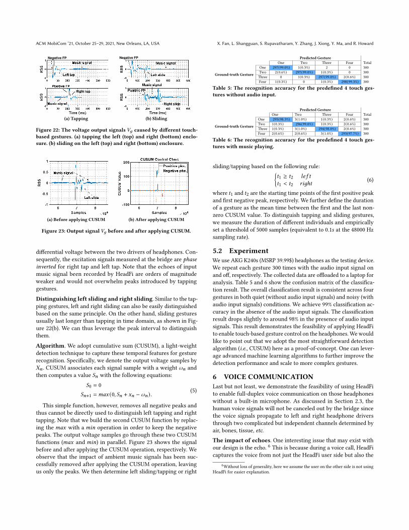
Heartbeat rate monitoring accuracy. We evaluate the accuracyof the heartbeat rate estimation using all 54 pairs of headphones.In particular, we categorize these headphones into three groups,namely, circumaural headphones (C), supra-aural headphones (S),and in-ear model (IEM). The result is shown in Figure 21(a). Weobserve that HeadFi achieves consistently low error rate across allthree groups of headphones. Circumaural headphones (C) achievethe lowest error rate both in the absence (1.37%, C) and presence(1.42%, C-M) of audio input signals, followed by supra-aural head-phones (1.40% and 1.68% in these two cases, respectively). HeadFiachieves the highest error rate for the IEM headphones: around1.64% and 2.42% in the absence (IEM) and presence (IEM-M) ofaudio input signals, respectively. While the intrinsic reason behindthis performance drop is unknown, one possible reason could bethat IEM headphones have less contact area with skins and thus
(a) Impact of ambient noise. (b) Impact of body movement.
Figure 21: Error rate of the heartbeat rate estimation. (a) We mea-sure the error rate both in the absence (the first three columns) andin the presence (the last three columns) of the audio input signal.(b) We measure the error rate both in the absence and presence ofstrong body movements.
receive the weakest vibration signals compared to the other twotypes of headphones. The maximum error rate achieved by HeadFiis around 3%, which still satisfies the requirement (less than 5%)for commercial heartbeat monitoring systems [49]. These resultsdemonstrate the feasibility of using HeadFi to measure user’s heart-beat rate even in the presence of strong interference signals (e.g.,music).
Impact of body movement. In this experiment, 27 participants(including 7 females and 20 males between 27 to 55 years old) areasked to put on/off the headphones occasionally during the testing,which brings in a strong interference signal. Figure 21(b) showsthe error rate. We also show the error rate in the absence of bodymovement for comparison. We observe a slight increase (0.59% onaverage) in the error rate in the presence of body movements, whilethe overall error rate is still less than 3%, well below the requirementfor commercial heartbeat monitoring systems (< 5%).
5 TOUCH-BASED GESTURE RECOGNITIONWe next demonstrate the feasibility of transforming the enclosuresof the non-smart headphones into virtual touchpads using HeadFi.The rationale behind this is that the variation in the output voltage𝑉𝑔 caused by different gestures manifests unique features in bothspatial and temporal domains. Without loss of generality, we definefour touch-based gestures: 𝑖) tapping the left enclosure − pauseor play; 𝑖𝑖) tapping the right enclosure − mute; 𝑖𝑖𝑖) sliding on theleft enclosure − volume up and 𝑖𝑣) sliding on the right enclosure− volume down. Note that the gestures that can be supported byHeadFi are not limited to these four gestures.
5.1 Signal Processing
Distinguishing left tapping and right tapping. We invite a vol-unteer to tap the left and right enclosure of one pair of headphonesand record the RSS out of HeadFi. As shown in Figure 22(a), whenthere is a tap on the headphones, we can always observe multipleRSS peaks. In particular, when the user taps the left enclosure, thereis a negative peak followed by a positive peak, as shown in Figure22(a) (top). In contrast, the positive peak shows up ahead of thenegative peak when the user taps the right enclosure (Figure 22(a)(bottom)). This is because the Wheatstone bridge measures the
ACM MobiCom ’21, October 25–29, 2021, New Orleans, LA, USA X. Fan, L. Shangguan, S. Rupavatharam, Y. Zhang, J. Xiong, Y. Ma, and R. Howard
Negative FP
(a) Tapping
Negative FP
(b) Sliding
Figure 22: The voltage output signals 𝑉𝑔 caused by different touch-based gestures. (a) tapping the left (top) and right (bottom) enclo-sure. (b) sliding on the left (top) and right (bottom) enclosure.
(a) Before applying CUSUM (b) After applying CUSUM
Figure 23: Output signal𝑉𝑔 before and after applying CUSUM.
differential voltage between the two drivers of headphones. Con-sequently, the excitation signals measured at the bridge are phaseinverted for right tap and left tap. Note that the echoes of inputmusic signal been recorded by HeadFi are orders of magnitudeweaker and would not overwhelm peaks introduced by tappinggestures.
Distinguishing left sliding and right sliding. Similar to the tap-ping gestures, left and right sliding can also be easily distinguishedbased on the same principle. On the other hand, sliding gesturesusually last longer than tapping in time domain, as shown in Fig-ure 22(b). We can thus leverage the peak interval to distinguishthem.
Algorithm. We adopt cumulative sum (CUSUM), a light-weightdetection technique to capture these temporal features for gesturerecognition. Specifically, we denote the output voltage samples by𝑋𝑛 . CUSUM associates each signal sample with a weight 𝜔𝑛 andthen computes a value 𝑆𝑛 with the following equations:
𝑆0 = 0𝑆𝑛+1 =𝑚𝑎𝑥 (0, 𝑆𝑛 + 𝑥𝑛 − 𝜔𝑛) .
(5)
This simple function, however, removes all negative peaks andthus cannot be directly used to distinguish left tapping and righttapping. Note that we build the second CUSUM function by replac-ing the 𝑚𝑎𝑥 with a 𝑚𝑖𝑛 operation in order to keep the negativepeaks. The output voltage samples go through these two CUSUMfunctions (𝑚𝑎𝑥 and 𝑚𝑖𝑛) in parallel. Figure 23 shows the signalbefore and after applying the CUSUM operation, respectively. Weobserve that the impact of ambient music signals has been suc-cessfully removed after applying the CUSUM operation, leavingus only the peaks. We then determine left sliding/tapping or right
Predicted GestureOne Two Three Four Total
Ground-truth Gesture
One 297(99.0%) 1(0.3%) 2 0 300Two 2(0.6%) 297(99.0%) 1(0.3%) 0 300Three 0 1(0.3%) 297(99.0%) 2(0.6%) 300Four 1(0.3%) 0 1(0.3%) 298(99.3%) 300
Table 5: The recognition accuracy for the predefined 4 touch ges-tures without audio input.
Predicted GestureOne Two Three Four Total
Ground-truth Gesture
One 295(98.3%) 3(1.0%) 1(0.3%) 2(0.6%) 300Two 1(0.3%) 296(99.0%) 1(0.3%) 2(0.6%) 300Three 1(0.3%) 3(1.0%) 294(98.0%) 2(0.6%) 300Four 2(0.6%) 2(0.6%) 3(1.0%) 293(97.7%) 300
Table 6: The recognition accuracy for the predefined 4 touch ges-tures with music playing.
sliding/tapping based on the following rule:{𝑡1 ≥ 𝑡2 𝑙𝑒 𝑓 𝑡
𝑡1 < 𝑡2 𝑟𝑖𝑔ℎ𝑡(6)
where 𝑡1 and 𝑡2 are the starting time points of the first positive peakand first negative peak, respectively. We further define the durationof a gesture as the mean time between the first and the last non-zero CUSUM value. To distinguish tapping and sliding gestures,we measure the duration of different individuals and empiricallyset a threshold of 5000 samples (equivalent to 0.1𝑠 at the 48000 Hzsampling rate).
5.2 ExperimentWe use AKG K240s (MSRP 39.99$) headphones as the testing device.We repeat each gesture 300 times with the audio input signal onand off, respectively. The collected data are offloaded to a laptop foranalysis. Table 5 and 6 show the confusion matrix of the classifica-tion result. The overall classification result is consistent across fourgestures in both quiet (without audio input signals) and noisy (withaudio input signals) conditions. We achieve 99% classification ac-curacy in the absence of the audio input signals. The classificationresult drops slightly to around 98% in the presence of audio inputsignals. This result demonstrates the feasibility of applying HeadFito enable touch-based gesture control on the headphones.Wewouldlike to point out that we adopt the most straightforward detectionalgorithm (i.e., CUSUM) here as a proof-of-concept. One can lever-age advanced machine learning algorithms to further improve thedetection performance and scale to more complex gestures.
6 VOICE COMMUNICATIONLast but not least, we demonstrate the feasibility of using HeadFito enable full-duplex voice communication on those headphoneswithout a built-in microphone. As discussed in Section 2.3, thehuman voice signals will not be canceled out by the bridge sincethe voice signals propagate to left and right headphone driversthrough two complicated but independent channels determined byair, bones, tissue, etc.
The impact of echoes. One interesting issue that may exist withour design is the echo. 6 This is because during a voice call, HeadFicaptures the voice from not just the HeadFi user side but also the
6Without loss of generality, here we assume the user on the other side is not usingHeadFi for easier explanation.
HeadFi: Bringing Intelligence to All Headphones ACM MobiCom ’21, October 25–29, 2021, New Orleans, LA, USA
(a) Objective evaluation. (b) Subjective evaluation.
Figure 24: (a) Objective and (b) subjective evaluations on the qualityof voice call over different types of headphones.
other side at the headphone’s diaphragm. Both captured voiceswill be transmitted to the other side. Thus, the other side mayhear an echo of her own voice. Fortunately, this issue is alreadyaddressed by the service providers. To provide high-quality voicecommunication, service providers usually run sophisticated signalcancellation algorithms at the base station to remove echoes beforetransmitting the voice signals to the receiver [2]. Therefore, echoeswould not be a problem and the evaluation results also confirm this.Next, we present our evaluation results in voice communication.
6.1 Experiment
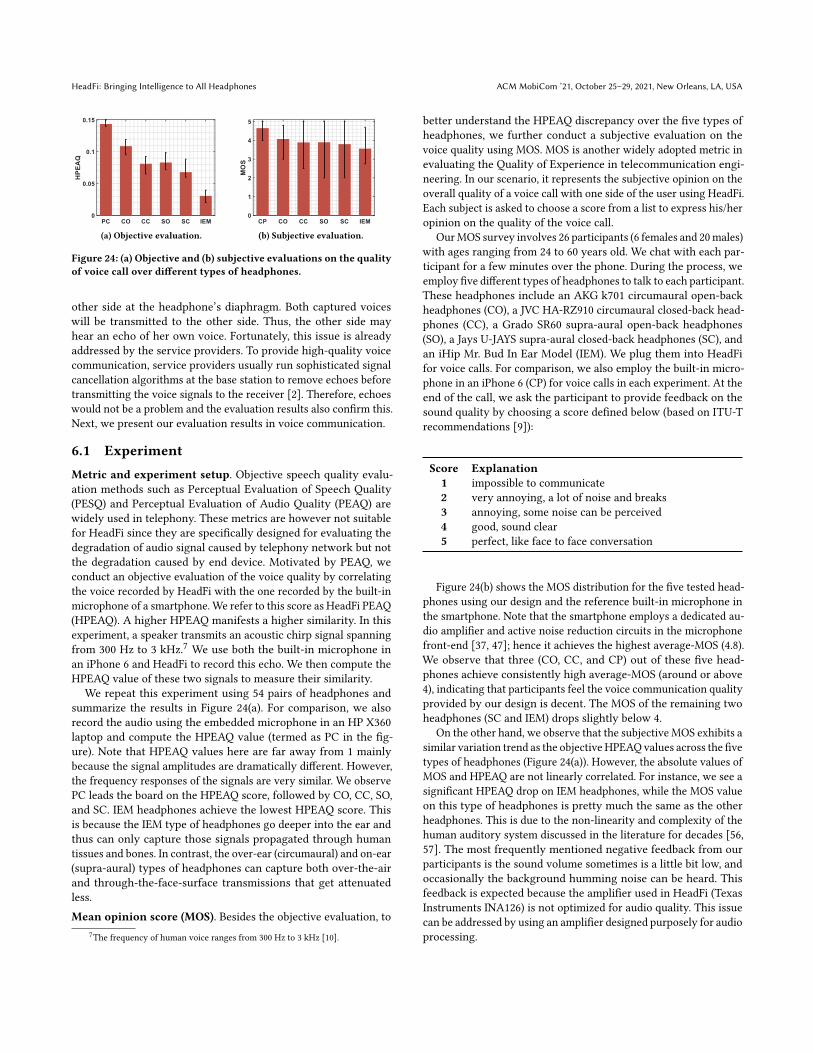
Metric and experiment setup. Objective speech quality evalu-ation methods such as Perceptual Evaluation of Speech Quality(PESQ) and Perceptual Evaluation of Audio Quality (PEAQ) arewidely used in telephony. These metrics are however not suitablefor HeadFi since they are specifically designed for evaluating thedegradation of audio signal caused by telephony network but notthe degradation caused by end device. Motivated by PEAQ, weconduct an objective evaluation of the voice quality by correlatingthe voice recorded by HeadFi with the one recorded by the built-inmicrophone of a smartphone. We refer to this score as HeadFi PEAQ(HPEAQ). A higher HPEAQ manifests a higher similarity. In thisexperiment, a speaker transmits an acoustic chirp signal spanningfrom 300 Hz to 3 kHz.7 We use both the built-in microphone inan iPhone 6 and HeadFi to record this echo. We then compute theHPEAQ value of these two signals to measure their similarity.
We repeat this experiment using 54 pairs of headphones andsummarize the results in Figure 24(a). For comparison, we alsorecord the audio using the embedded microphone in an HP X360laptop and compute the HPEAQ value (termed as PC in the fig-ure). Note that HPEAQ values here are far away from 1 mainlybecause the signal amplitudes are dramatically different. However,the frequency responses of the signals are very similar. We observePC leads the board on the HPEAQ score, followed by CO, CC, SO,and SC. IEM headphones achieve the lowest HPEAQ score. Thisis because the IEM type of headphones go deeper into the ear andthus can only capture those signals propagated through humantissues and bones. In contrast, the over-ear (circumaural) and on-ear(supra-aural) types of headphones can capture both over-the-airand through-the-face-surface transmissions that get attenuatedless.Mean opinion score (MOS). Besides the objective evaluation, to
7The frequency of human voice ranges from 300 Hz to 3 kHz [10].
better understand the HPEAQ discrepancy over the five types ofheadphones, we further conduct a subjective evaluation on thevoice quality using MOS. MOS is another widely adopted metric inevaluating the Quality of Experience in telecommunication engi-neering. In our scenario, it represents the subjective opinion on theoverall quality of a voice call with one side of the user using HeadFi.Each subject is asked to choose a score from a list to express his/heropinion on the quality of the voice call.
OurMOS survey involves 26 participants (6 females and 20males)with ages ranging from 24 to 60 years old. We chat with each par-ticipant for a few minutes over the phone. During the process, weemploy five different types of headphones to talk to each participant.These headphones include an AKG k701 circumaural open-backheadphones (CO), a JVC HA-RZ910 circumaural closed-back head-phones (CC), a Grado SR60 supra-aural open-back headphones(SO), a Jays U-JAYS supra-aural closed-back headphones (SC), andan iHip Mr. Bud In Ear Model (IEM). We plug them into HeadFifor voice calls. For comparison, we also employ the built-in micro-phone in an iPhone 6 (CP) for voice calls in each experiment. At theend of the call, we ask the participant to provide feedback on thesound quality by choosing a score defined below (based on ITU-Trecommendations [9]):
Score Explanation1 impossible to communicate2 very annoying, a lot of noise and breaks3 annoying, some noise can be perceived4 good, sound clear5 perfect, like face to face conversation
Figure 24(b) shows the MOS distribution for the five tested head-phones using our design and the reference built-in microphone inthe smartphone. Note that the smartphone employs a dedicated au-dio amplifier and active noise reduction circuits in the microphonefront-end [37, 47]; hence it achieves the highest average-MOS (4.8).We observe that three (CO, CC, and CP) out of these five head-phones achieve consistently high average-MOS (around or above4), indicating that participants feel the voice communication qualityprovided by our design is decent. The MOS of the remaining twoheadphones (SC and IEM) drops slightly below 4.
On the other hand, we observe that the subjective MOS exhibits asimilar variation trend as the objective HPEAQvalues across the fivetypes of headphones (Figure 24(a)). However, the absolute values ofMOS and HPEAQ are not linearly correlated. For instance, we see asignificant HPEAQ drop on IEM headphones, while the MOS valueon this type of headphones is pretty much the same as the otherheadphones. This is due to the non-linearity and complexity of thehuman auditory system discussed in the literature for decades [56,57]. The most frequently mentioned negative feedback from ourparticipants is the sound volume sometimes is a little bit low, andoccasionally the background humming noise can be heard. Thisfeedback is expected because the amplifier used in HeadFi (TexasInstruments INA126) is not optimized for audio quality. This issuecan be addressed by using an amplifier designed purposely for audioprocessing.
ACM MobiCom ’21, October 25–29, 2021, New Orleans, LA, USA X. Fan, L. Shangguan, S. Rupavatharam, Y. Zhang, J. Xiong, Y. Ma, and R. Howard
7 RELATEDWORK
Touch-based gesture control. The touch-based gesture controlis usually realized by adding capacitive or resistive sensors intoheadphones. These sensors typically measure changes in resis-tance or capacitance to detect gestures such as touch. Many smartheadphones including Microsoft Surface Headphones [14], Sony1000XM3 headphones [4], Zealot B21 headphones [3], and BoseNC700 headphones [5] come with this function. Our system canserve as a supplementary solution to conveniently transform those“dumb” headphones into smart headphones.
Physiological sensing. There is a growing trend in embeddingsensors in headphones for physiological sensing. Heartbeat rate,respiratory rate, and blood pressure can be monitored using electro-cardiography (ECG), ballistocardiography (BCG), and photoplethys-mography (PPG) [28, 51, 52, 58, 61]. Bui et al. adopted PPG sensorsand developed an in-ear system to measure the blood pressure [23].Anh et al. proposed to customize an in-ear sensor to measure thebrain activities [45]. Rupavatharam et al. proposed to use the IMUin a pair of dedicated designed headphones to monitor jaw clench-ing [55]. Roddiger et al. developed a respiration rate monitoringsystem using the embedded IMU [53]. There is also an open-sourcemulti-sensor integrated research platform, eSense, for earable com-puting research [16]. These sensing systems and platforms rely ondedicated sensors that add weight, require additional form factordesign, and incur higher cost and power consumption.
User authentication. The unique physical structure of the earcanal can be used to authenticate users. High-frequency audio sig-nals are bounced off the ear canal to serve as a unique feature forauthentication. Arakawa et al. proposed to use the Mel-frequencycepstral coefficients (MFCC) instead of the frequency-domain trans-fer function to achieve a higher authentication accuracy [21]. Hi-gashiguchi et al. proposed to use the built-in microphones in acellphone to perform ear-related user authentications [34]. Akker-mans et al. and Mahto et al. studied the feasibility of using inaudiblepilot tones for user authentications [20, 43]. Gao et al. designed anear-related user authentication system using commercially avail-able headphones [33]. These techniques, however, rely heavily onauxiliary and application-specific sensors placed around ear canalthat add size and even affect the quality of the audio output whichis the primary function of headphones. HeadFi instead bring intel-ligence to “dumb” headphones without requiring extra sensors orcompromising the output signal quality.
8 DISCUSSIONHeadFi leaves room for further investigations, as discussed below:
The effect on user experience. HeadFi converts the audio outputinto mono for sensing and such audio conversion may affect userexperience in some, if not all applications, as we discussed below.𝑖) Voice call. As stereo itself is not supported for voice calls, HeadFidoes not affect the user experience on voice calls. 𝑖𝑖) Music playing.The user experience can get compromised for stereotype musicsince the audio output will be converted into mono by HeadFi. 𝑖𝑖𝑖)User identification. HeadFi has limited influence on user experi-ence as user identification takes a very short time and happensoccasionally in the time domain. 𝑖𝑣) Physiological sensing. These
applications such as heartbeat rate monitoring usually require con-tinuous sensing. The user experience would thus be affected. Tominimize such impact, we include a switch (𝑆1 in Figure 8) in HeadFi,allowing the user to turn on/off HeadFi as needed. A more compre-hensive solution could be using a separate matching network toindependently balance the left and right drivers rather than balanc-ing them as a single pair. This allows the user to retain the stereoexperience in the presence of HeadFi.
HeadFi vs. dedicated sensors. While adding dedicated sensorsmay achieve a better user experience in some applications, it hascertain drawbacks as we discussed below. From the user’s point ofview, adding sensors to their headphones is not always feasible asit requires hardware modifications (e.g., embedding sensors intothe headphones) which may break the internal structure, layout,and circuit of the headphones. In contrast, HeadFi serves as a plug-in peripheral wiring the headphones and pairing device (e.g., asmartphone) without a need of any hardware modification. On theother hand, from the manufacture’s point of view, adding dedicatedsensors to headphones usually incurs an extra cost to both head-phone hardware and the assembly line. In contrast, HeadFi relies onlow-cost hardware that is as simple as two resistors, making it a cost-effective solution. In addition, as most of the headphones ownedby users or shipped to the market nowadays are still non-smartones, HeadFi thus can serve as an important alternative solutionto existing smart headphone design by turning those non-smartheadphones on hand into smart ones, thereby paving the way forrealizing earable intelligence at an unprecedented scale.
9 CONCLUSIONWe have presented the design, implementation, and evaluation ofHeadFi, a low-power peripheral to bring intelligence to headphones.HeadFi employs the pair of drivers inside headphones as a versatilesensor to enable new functionalities as opposed to adding embeddedsensors. This design can potentially upgrade existing non-smartheadphones into intelligent ones. We prototype HeadFi on PCBboard and demonstrate the potential of HeadFi by showcasing fourrepresentative applications using 54 pairs of headphones.
ACKNOWLEDGEMENTSWe thank the anonymous reviewers and shepherd for their insight-ful comments. We thank Dr. Lin Zhong for providing us insightfulfeedback on this work. We also thank Mr. Gefeng Wang for provid-ing us testing headphones. This work is supported by 2030 NationalKey AI Program of China Grant No. 2018AAA0100500 and the KeyResearch Program of Frontier Sciences, CAS, Grant No. ZDBS-LY-JSC001. Corresponding author: [email protected]
REFERENCES[1] 2014. Gig Fix: Turn Your Headphones Into A Mic. Webpage.[2] 2014. Voice Quality Enhancement and Echo Cancellation. .[3] 2018. B21 Super Bass Wireless Bluetooth Headphone Stereo Touch Control
Headset Noise Cancelling With Micro. Webpage.[4] 2018. Wireless Noise Canceling Stereo Headset WH-1000XM3. Webpage.[5] 2019. Bose Noise Cancelling Headphones 700. Webpage.[6] 2019. CMS50D1A GEHP040AHUS pulse oximeter. Webpage.[7] 2019. Earphones and Headphones Market Size, Industry Report. Webpage.[8] 2019. Global unit sales of headphones and headsets from 2013 to 2017. Website.[9] 2019. P.800.1 : Mean opinion score (MOS) terminology. Webpage.[10] 2019. Voice frequency. Webpage.
HeadFi: Bringing Intelligence to All Headphones ACM MobiCom ’21, October 25–29, 2021, New Orleans, LA, USA
[11] 2020. BOSE QC-35 Wireless Headphones.[12] 2020. The Differential Amplifier. Webpage.[13] 2020. How Sound Works. Webpage.[14] 2020. Microsoft Surface Headphones. Website.[15] 2020. MiniDSP E.A.R.S. Webpage.[16] 2020. A Research Space for EARABLE COMPUTING. Webpage.[17] 2020. Samgsung Galaxy Buds. Website.[18] 2021. Apple Airpods. Website.[19] 2021. Hifi Shark - Used, Second hand and Pre-owned Hifi. Webpage.[20] Anton HM Akkermans, Tom AM Kevenaar, and Daniel WE Schobben. 2005.
Acoustic ear recognition for person identification. In AutoID. IEEE.[21] Takayuki Arakawa, Takafumi Koshinaka, Shohei Yano, Hideki Irisawa, Ryoji
Miyahara, and Hitoshi Imaoka. 2016. Fast and accurate personal authenticationusing ear acoustics. In APSIPA. IEEE.
[22] Yoshua Bengio and Yves Grandvalet. 2004. No unbiased estimator of the varianceof k-fold cross-validation. Journal of machine learning research (2004).
[23] Nam Bui, Nhat Pham, Jessica Jacqueline Barnitz, Zhanan Zou, Phuc Nguyen,Hoang Truong, Taeho Kim, Nicholas Farrow, Anh Nguyen, Jianliang Xiao, et al.2019. eBP: A Wearable System For Frequent and Comfortable Blood PressureMonitoring From User’s Ear. In MobiCom.
[24] Bruce Carter. 2009. Op Amp noise theory and applications, 12.3.2 Thermal Noise.Elsevier.
[25] Bruce Carter and Thomas R Brown. 2001. Handbook of operational amplifierapplications. Texas Instruments Dallas, Tex, USA.
[26] Justin Chan, Sharat Raju, Rajalakshmi Nandakumar, Randall Bly, and Shyam-nath Gollakota. 2019. Detecting middle ear fluid using smartphones. Sciencetranslational medicine 11, 492 (2019).
[27] John Clarke, Claudia D Tesche, and RP Giffard. 1979. Optimization of dc SQUIDvoltmeter and magnetometer circuits. Journal of Low Temperature Physics (1979).
[28] David Da He, Eric S Winokur, and Charles G Sodini. 2012. An ear-worn continu-ous ballistocardiogram (BCG) sensor for cardiovascular monitoring. In EMBC.IEEE.
[29] Jesse Davis and Mark Goadrich. 2006. The relationship between Precision-Recalland ROC curves. In Proceedings of the 23rd international conference on Machinelearning. 233–240.
[30] Christian C Enz and Gabor C Temes. 1996. Circuit techniques for reducing theeffects of op-amp imperfections: autozeroing, correlated double sampling, andchopper stabilization. Proc. IEEE (1996).
[31] Xiaoran Fan, Daewon Lee, Yuan Chen, Colin Prepscius, Volkan Isler, Larry Jackel,H Sebastian Seung, and Daniel Lee. 2020. Acoustic collision detection andlocalization for robot manipulators. IROS.
[32] Joel Gak, Matías Miguez, Martín Bremermann, and Alfredo Arnaud. 2008. Onthe reduction of thermal and flicker noise in ENG signal recording amplifiers.Analog Integrated Circuits and Signal Processing (2008).
[33] Yang Gao, Wei Wang, Vir V Phoha, Wei Sun, and Zhanpeng Jin. 2019. EarEcho:Using Ear Canal Echo for Wearable Authentication. IMWUT (2019).
[34] Yutaka Higashiguchi, Yoshinobu Kajikawa, and Shunsuke Kita. 2017. A personalauthentication system based on pinna related transfer function. In ICBAKE. IEEE.
[35] Karl Hoffmann. 1974. Applying the Wheatstone bridge circuit. HBM Germany.[36] Texas Instruments. 2007. Noise analysis in operational amplifier circuits. Appli-
cation Report, SLVA043B (2007).[37] Thomas M Jensen, Vladan Bajic, and Andrew P Bright. 2016. Active noise
cancellation using multiple reference microphone signals. US Patent 9,330,652.[38] Liang-Ting Jiang and Joshua R Smith. 2012. Seashell effect pretouch sensing for
robotic grasping. In ICRA. IEEE.[39] Agnès Job, Paul Grateau, and Jacques Picard. 1998. Intrinsic differences in hearing
performances between ears revealed by the asymmetrical shooting posture inthe army. Hearing research (1998).
[40] Ron Kapusta, Haiyang Zhu, and Colin Lyden. 2014. Sampling circuits that breakthe kT/C thermal noise limit. IEEE Journal of Solid-State Circuits (2014).
[41] Ronald A Kapusta, Katsufumi Nakamura, et al. 2007. Methods and apparatus forreducing thermal noise. US Patent 7,298,151.
[42] F Laurain King and Doreen Kimura. 1972. Left-ear superiority in dichotic percep-tion of vocal nonverbal sounds. Canadian Journal of Psychology/Revue canadiennede psychologie (1972).
[43] Shivangi Mahto, Takayuki Arakawa, and Takafumi Koshinak. 2018. Ear acous-tic biometrics using inaudible signals and its application to continuous userauthentication. In EUSIPCO. IEEE.
[44] Henrik Møller, Dorte Hammershøi, Clemen Boje Jensen, and Michael FriisSørensen. 1995. Transfer characteristics of headphones measured on human ears.Journal of the Audio Engineering Society (1995).
[45] Anh Nguyen, Raghda Alqurashi, Zohreh Raghebi, Farnoush Banaei-Kashani,Ann C Halbower, and Tam Vu. 2016. A lightweight and inexpensive in-earsensing system for automatic whole-night sleep stage monitoring. In SenSys.
[46] Viet Nguyen, Siddharth Rupavatharam, Luyang Liu, Richard Howard, and MarcoGruteser. 2019. HandSense: capacitive coupling-based dynamic, micro fingergesture recognition. In SenSys.
[47] Guy C Nicholson. 2013. Active noise cancellation decisions in a portable audio
device. US Patent 8,515,089.[48] Sean Olive, Omid Khonsaripour, and Todd Welti. 2018. A Survey and Analysis of
Consumer and Professional Headphones Based on Their Objective and SubjectivePerformances. In Audio Engineering Society Convention 145. Audio EngineeringSociety.
[49] Alexandros Pantelopoulos and Nikolaos G Bourbakis. 2009. A survey on wearablesensor-based systems for health monitoring and prognosis. IEEE Transactions onSystems, Man, and Cybernetics, Part C (Applications and Reviews) (2009).
[50] Melih Papila, Raphael T Haftka, Toshikazu Nishida, and Mark Sheplak. 2006.Piezoresistive microphone design pareto optimization: tradeoff between sensitiv-ity and noise floor. Journal of microelectromechanical systems (2006).
[51] Ming-Zher Poh, Kyunghee Kim, Andrew Goessling, Nicholas Swenson, andRosalind Picard. 2010. Cardiovascular monitoring using earphones and a mobiledevice. IEEE Pervasive Computing (2010).
[52] Ming-Zher Poh, Kyunghee Kim, Andrew D Goessling, Nicholas C Swenson, andRosalind W Picard. 2009. Heartphones: Sensor earphones and mobile applicationfor non-obtrusive health monitoring. In ISWC. IEEE.
[53] Tobias Röddiger, Daniel Wolffram, David Laubenstein, Matthias Budde, andMichael Beigl. 2019. Towards Respiration Rate Monitoring Using an In-EarHeadphone Inertial Measurement Unit. In EarComp.
[54] Peter J Rousseeuw and Annick M Leroy. 2005. Robust regression and outlierdetection. John wiley & sons.
[55] Siddharth Rupavatharam and Marco Gruteser. 2019. Towards In-Ear Inertial JawClenching Detection. In EarComp.
[56] Otto Stuhlman Jr. 1937. The nonlinear transmission characteristics of the auditoryossicles. The Journal of the Acoustical Society of America (1937).
[57] Frédéric E Theunissen, Kamal Sen, and Allison J Doupe. 2000. Spectral-temporalreceptive fields of nonlinear auditory neurons obtained using natural sounds.Journal of Neuroscience (2000).
[58] Stefan Vogel, Markus Hülsbusch, Thomas Hennig, Vladimir Blazek, and SteffenLeonhardt. 2009. In-ear vital signs monitoring using a novel microoptic reflectivesensor. IEEE Transactions on Information Technology in Biomedicine (2009).
[59] Joseph C Volpe Jr. 2008. Heart rate monitor for controlling entertainment devices.US Patent 7,354,380.
[60] Susan E Voss and Jont B Allen. 1994. Measurement of acoustic impedance andreflectance in the human ear canal. The Journal of the Acoustical Society ofAmerica (1994).
[61] Eric S Winokur, David Da He, and Charles G Sodini. 2012. A wearable vital signsmonitor at the ear for continuous heart rate and pulse transit time measurements.In EMBS. IEEE.
[62] Myung-Gyoo Won, Jae-hoon Kim, and Jong-wook Park. 2006. Temperaturesensing circuit for use in semiconductor integrated circuit. US Patent 7,107,178.
[63] Daniel Yum. 1991. Bandgap voltage reference circuit. US Patent 5,053,640.
A APPENDIXA.1 List of headphones in experimentsTable 7 is the list of headphones used in our experiments. Notesome headphones are discontinued. The estimated prices for thediscontinued headphones are sourced from Hifi-Shark [19]. Takea departure from other consumer electronics like computers orcellphones, headphones are built to last, especially the traditionalheadphones. Many of our tested headphones are manufactured 20years ago and they still work fine.

ACM MobiCom ’21, October 25–29, 2021, New Orleans, LA, USA X. Fan, L. Shangguan, S. Rupavatharam, Y. Zhang, J. Xiong, Y. Ma, and R. Howard
No. Type Name Driver type Estimated Price ($) Year01 Circumaural Sennheiser HD800S Dynamic 1,699.95 201502 Circumaural Verum Audio Verum Planar 349.00 201803 Circumaural Sennheiser HD58x Dynamic 150.00 201704 Circumaural Sennheiser HD650 Dynamic 499.95 200305 Circumaural Sennheiser HD540II Dynamic 200.00 198606 Circumaural Harman Kardon HARKAR NC Dynamic 299.95 201307 Circumaural JVC HA-RZ910 Dynamic 78.54 201408 Circumaural Equation RP-21 Dynamic 99.95 201009 Circumaural AKG K500 Dynamic 150.00 199110 Circumaural AKG K701 Dynamic 449.00 200511 Circumaural AKG K812 Dynamic 1,499.00 201312 Circumaural Monoprie M565C Planar 199.99 201813 Circumaural Focal Elear Dynamic 999.00 201714 Circumaural Focal Elex Dynamic 600.00 201715 Circumaural Sennheiser HD580 Dynamic 200.00 199116 Circumaural Sennheiser HD540G Dynamic 400.00 198817 Circumaural Hifiman Susvara Planar 6,000.00 201618 Circumaural Hifiman HE500 Planar 700.00 201019 Circumaural Audeze LCD2 Planar 995.00 201020 Circumaural Beyerdynamic T1 Dynamic 999.00 200921 Circumaural Sony MDR R10 Dynamic 15,000.00 198922 Circumaural AKG K240s Dynamic 39.99 200123 Circumaural Abyss AB-1266 Planar 6,000.00 201224 Circumaural Abyss AB-1266 Phi Planar 7,000.00 201725 Circumaural Kennerton Thror Planar 3,080.00 201826 Circumaural Hifiman HE6 Planar 1,000.00 201027 Circumaural Sennheiser HD580 Jubilee Dynamic 500.00 199528 Circumaural Sennheiser HD600 Dynamic 399.95 199729 Circumaural AKG K872 Dynamic 1,499.00 201630 Circumaural Audeze LCD3 Planar 1,945.00 201231 Circumaural Sennheiser HD224 Dynamic 49.00 197732 Supra-aural Koss Porta Pro Dynamic 49.99 198433 Supra-aural Grado SR60 Dynamic 69.00 199534 Supra-aural Koss KSC75x Dynamic 19.99 200435 Supra-aural BlueAnt Embrace Dynamic 200.00 201136 Supra-aural Equation Audio RP-15MC Dynamic 50.00 200437 Supra-aural Audio-Technica ATH-OR7 Dynamic 200.00 200938 Supra-aural Marshall Monitor II ANC Dynamic 319.99 201939 Supra-aural Spider PowerForce Dynamic 50.00 201240 Supra-aural Monoprice Pro Dynamic 29.99 201241 Supra-aural Musical Fidelity MF-100 Dynamic 199.00 201342 Supra-aural AKG Q460 Dynamic 129.90 201043 Supra-aural Beats Diamond Tears Dynamic 349.95 201244 Supra-aural Mackie MC-250 Dynamic 80.00 201945 Supra-aural Jays U-JAYS On Ear Dynamic 19.99 201746 In-ear Beats Heartbeats Dynamic 99.99 201247 In-ear Philips Fidelio S2 Dynamic 149.00 201348 In-ear Etymotic Research ER6i Armature 149.00 200449 In-ear SENFER DT6 Trio hybrid 35.00 201950 In-ear Beats urBeats Dynamic 99.99 201851 In-ear KEF M200 Duo dynamic 200.00 201352 In-ear Sennheiser HD405 Dynamic 35.00 200153 In-ear iHip Mr Bud Dynamic 3.60 201554 In-ear Insten In-ear Dynamic 2.99 2013
Table 7: List of headphones in our experiment.