Embed Size (px)
Citation preview
FOR TRAINING PURPOSES ONLY
HEADSET COMMUNICATION & REFUELING TRAINING
A/C Type: A320
FOR TRAINING PURPOSES ONLY
CONTENT:
COMMUNICATION WITH CREW
A/C TOWING STANDARD PROCEDURE AND INSTRUCTION
A320 REFUELING OPERATION
OPENING/CLOSING OF CARGO DOOR PROCEDURE
FINAL DEPARTURE WALK AROUND CHECKLIST
FOR TRAINING PURPOSES ONLY Page 1
COMMUNICATE TO CREW
I. Departure procedures:
A. General
The following intercom procedure is the normal procedure to be applied before departure. This
procedure is based upon a standard dialogue between the flight crew and the headset man and is
standard for all Company aircraft types.
Strict adherence to the procedure is necessary in order to ensure the safety of the ground
personnel and the aircraft during the start, push back and departure procedures.
B. Before engine start
Prior to engine start, the headset man will ensure that during the landing gear locking pins not
required for the start and push back procedures are removed and stowed on the aircraft.
Removal of landing gear locking pins must be recorded in techlog book by CRS holder. Safety
pin is installed at towing position on Nose Wheel Steering Deactivation Electrical Box.
During a pre-flight walk around check, flight crew will normally observe the landing gear
locking pins in place. They should confirm with the headset man that these have been
removed prior to engine start.
If the aircraft has been connected to a ground power unit and has a serviceable APU the
headset man will establish contact with the flight crew and confirm that the ground power unit
can be removed prior to engine start.
During the p e r i o d when the a i r c r a f t is a l m o s t ready for d i s p a t c h the headset man
may make contact with the flight crew to confirm that the parking brake has been set and that
the headset man are to connect the tow bar, or position the tow-bar-less tractor.
Push back should not be commenced until all the doors have been closed and the mobile stairs
or the jet way has been removed from the aircraft, together with all other ground equipment,
and confirmation with flight crew.
Once cockpit preparation is complete, all doors have been closed and a clearance received from
ATC for the start and push back the BEACON should be selected ON and the commander should
establish intercom contact with the headset man .
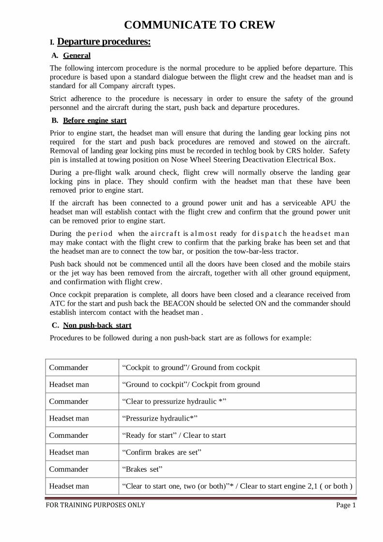
C. Non push-back start
Procedures to be followed during a non push-back start are as follows for example:
Commander “Cockpit to ground”/ Ground from cockpit
Headset man “Ground to cockpit”/ Cockpit from ground
Commander “Clear to pressurize hydraulic *”
Headset man “Pressurize hydraulic*”
Commander “Ready for start” / Clear to start
Headset man “Confirm brakes are set”
Commander “Brakes set”
Headset man “Clear to start one, two (or both)”* / Clear to start engine 2,1 ( or both )

FOR TRAINING PURPOSES ONLY Page 2
Commander “Starting one, two (or both)* / Starting engine two, one.
Commander “Monitor N1 speed”
Headset man “N1 speed rotating”
When start complete:
Commander “Start complete, disconnect” / Start complete, clear to disconnect, hand
signals on left/right
Headset man “Disconnecting” / Hand signals on left/right
The headset man will move clear of the aircraft (either left or right hand side). And give a
“thumbs up” signal when the aircraft is clear to move under its own power.
D. Push-back start
Procedures to be followed during a push-back start are as follows for example:
Example 1:
Commander “Cockpit to ground” / Ground from cockpit
Headset man “Ground to cockpit” / Cockpit from ground
Commander “Clear to pressurize hydraulic *”
Headset man “Pressurize hydraulic*”
Commander “Ready for push back and start” / Clear for push
Headset man “Brakes off ?” / Release brakes
Commander “Brakes off” / Brakes released, commence push back
Headset man “Commencing push back”
When clear to start.
Headset man “Clear to start one, two (or both)”* / Clear to start engine 2, 1 (or both)
Commander “Starting one, two (or both)** / Starting engine two, one.
Commander “Monitor N1 speed”
Headset man “N1 speed rotating”
When push back complete:
Headset man “Parking brakes” / Set parking brakes
Commander “Brakes parked” or “Packing brakes set” / Brakes set

FOR TRAINING PURPOSES ONLY Page 3
When start complete:
Commander “Start complete, disconnect” / Start complete, clear to disconnect, hand
signals on left/right side.
Headset man “Disconnecting” hand signals on left/right
The headset man will move clear of the aircraft (either left or right hand side) and give a
“thumbs up” signal when the ground equipment has been cleared of the aircraft and the
aircraft is clear to move under its own power.
II. Arrival procedures:
Once the aircraft arrives at the parking position the and the engines have been shut down and
the BEACON has be selected OFF the commander should make contact with the headset and
confirm that the aircraft chocks are in placed and that the park brake can be released.
A/C arrives at the parking position
- Monitor the engines have been shutdown.
- Monitor the parking brakes have been set: Packing brakes light come on
Communicate to the Flight crew:
Ground Ground to cockpit/ Cockpit from ground
Cockpit Cockpit to ground/ Ground from cockpit
Ground Parking brakes/ Confirm brakes are set
Cockpit Parking brakes set/ Brakes set
Ground Brakes packed/ Brakes set checked
- Monitor the BEACON lights have been selected OFF:
Communicate to the Flight crew:
Ground Ground to cockpit/ Cockpit from ground
Cockpit Cockpit to ground/ Ground from cockpit
Ground BEACON lights still ON
Cockpit BEACON set OFF
Ground BEACON OFF/ BEACON OFF checked
- Put chock on:
+ Confirm that the A/C has been chocked.
+ Confirm that the parking brakes can be released.
Ground Chock-in
Cockpit Packing brakes release/ Brakes released

FOR TRAINING PURPOSES ONLY Page 4
Ground Brakes released/ Brakes released checked
III. Alert call
It is extremely important to identify the precise nature of the abnormal condition observed and relay
this information to the flight crew.
A tail pipe fire for example requires dry motoring of the engine to extinguish the flames. An
undercowl fire however may require the crew to pull the engine fire handle and discharge the fire
suppressant. If the fire handle is pulled for a tail pipe fire, the engine cannot then be dry-motored,
and the fire will continue to burn as long as there is a fuel source.
Giving the wrong information can result in serious damage to the engine and aircraft and jeopardise
passenger and crew safety.
Ingestion risk/event:
Ground crew to Cockpit “Cockpit alert! Cockpit alert! Shutdown left/right engine….”
Engine tail pipe fire:
Headset man remains calm and inform cockpit of engine tailpipe and engine number: “Cockpit
alert! Cockpit alert! Tailpipe fire, left/right engine”. Then, headset man continue to report at regular
intervals on status of tailpipe fire.
Tow bar shear pin failure
Ground crew to Cockpit “Cockpit alert! Cockpit alert! Towbar sheared” (if towbar bolts sheared but
towbar does not separate).
Ground crew to Cockpit “Cockpit alert! Cockpit alert! Towbar separated” (if towbar separated).
Please refer to section “emergency procedure” of aircraft towing standard procedure instruction.
IV. Conventional Visual Signals
These signals are designed for the use of signalman, with hands illuminated as necessary to
facilitate observation by the pilot, and facing the aircraft. The meaning of the relevant signals
remains the same if bats, illuminated wands or torchlight’s are used. The numbering of the
signals is what have been used in the official documentation ICAO – Rules of the Air Annex 2.
“ALL CLEAR”
During the day: by the thumbs-up signal OR at night:
MANEUVERS 1- To proceed under further guidance by signalman

FOR TRAINING PURPOSES ONLY Page 5
Signalman directs pilot if traffic conditions on airport require this action.
2- Assigned bay
Arms above head in vertical position with palms facing inward.
3- Proceed to next signalman
Right or left arm down, other arm moved across the body and extended to indicate
direction of next signalman.
4- Move ahead
Arms a little aside, palms facing backward and repeatedly moved upward-backward from
shoulder height.
5- Turn
a) Turn to your left:
Right arm downward, left arm repeatedly moved upward-backward. Speed of arm movement
indicating rate of turn.
b) Turn to your right:
Right arm downward, left arm repeatedly moved upward-backward. Speed of arm movement
indicating rate of turn
6- Slow down
Arms down with palms toward ground then moved up and down several times.
FOR TRAINING PURPOSES ONLY Page 6
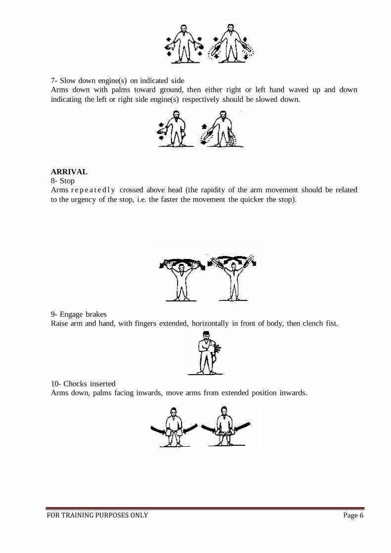
7- Slow down engine(s) on indicated side
Arms down with palms toward ground, then either right or left hand waved up and down
indicating the left or right side engine(s) respectively should be slowed down.
ARRIVAL
8- Stop
Arms r e p e a t e d l y crossed above head (the rapidity of the arm movement should be related
to the urgency of the stop, i.e. the faster the movement the quicker the stop).
9- Engage brakes
Raise arm and hand, with fingers extended, horizontally in front of body, then clench fist.
10- Chocks inserted
Arms down, palms facing inwards, move arms from extended position inwards.
FOR TRAINING PURPOSES ONLY Page 7
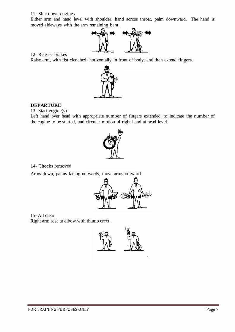
11- Shut down engines
Either arm and hand level with shoulder, hand across throat, palm downward. The hand is
moved sideways with the arm remaining bent.
12- Release brakes
Raise arm, with fist clenched, horizontally in front of body, and then extend fingers.
DEPARTURE 13- Start engine(s)
Left hand over head with appropriate number of fingers extended, to indicate the number of
the engine to be started, and circular motion of right hand at head level.
14- Chocks removed
Arms down, palms facing outwards, move arms outward.
15- All clear
Right arm rose at elbow with thumb erect.

FOR TRAINING PURPOSES ONLY Page 8
A/C TOWING STANDARD PROCEDURE INSTRUCTION
1. The preparation procedures before towing A/C
Cockpit man must be CRS holder or Pilot in command (PIC)
- Turn on APU in cockpit. If APU is INOP, he should inform GSE to prepare GPU and cable
to supply the electric power.
- Adjust the seat and do not put feet on the pedal, maintain A/C in the condition of parking
brake set to prepare towing operating.
- Turn on the position light of A/C. If A/C towing is performed at night, turn on the logo light.
- Stand by to turn on the hydraulic system, turn on anti-collision light and stand by to release
parking brake.
Headset man
- Confirm the jet way withdrew and the clearance of GSE. All the entry doors should be
completely close and locked.
- Check all down lock pins plug in landing gears and ensure the steering pin being properly
set
- Confirm flap/slat is in the up condition, and then inform cockpit man to build up the
hydraulic system. The cockpit man should confirm the pressure is in normal condition.
- Check plug-pin of tow-bar is completely locked, confirm the mechanic remove the chocks
and wing walker is in position.
- Put on the headset and next to the nose wheel in safety position and keep in connection with
cockpit main and towing tractor driver.
- Establish permission from control tower to tow.
2. The procedures of A/C towing
- Headset man confirms all personnel are in position.
- Headset man contact with cockpit man to release parking brake and turn on the anti-collision
light.
- When the headset man confirm parking brake is released and anti-collision light is on, he
should make a gesture to towing tractor driver --raise right hand with fist (means parking
brake is set), release the fist (means parking brake is released). Then thumb up to mean the
A/C is ready to tow.
3. The procedures during A/C towing
Headset man
- Contact with cockpit man with headset and keep contact whole the time.
- Observe the speed of A/C towing, turning angle, the condition of tow-bar and the clearance
of ground, and inform the conditions to driver.
- If the A/C is temporarily stopped by other reasons, restrain to ask cockpit man to set parking
brake. Once re-towing A/C, he should face to towing driver first with thumb up to confirm
towing driver didn’t set paring brake.
- If the shear pin of tow-bar is broken, he should inform towing driver with walkie-talkie to
slow down the speed. If the tow-bar is separated from A/C, he should inform cockpit man
with headset or walkie-talkie to brake A/C immediately and also inform towing driver to
take immediately actions.
Cockpit man
- Do not brake and operate flight control system of A/C except for emergency conditions or
informed by headset man.

FOR TRAINING PURPOSES ONLY Page 9
Note: The cockpit man is prohibited from putting his feet on brake pedal during A/C towing.
- The cockpit man is prohibited from testing the outer lights in cockpit during A/C towing at
night.
- Keep alert during towing A/C.
- If the APU or GPU of towing tractor is malfunctioned, he should confirm the brake pressure
is still within the normal condition first and continue to tow A/C. However, the towing
should keep the speed under 5 km/hr.
4. The procedures after towing A/C to the destination points
a) When towing A/C to the destination point, the towing driver should step the brake slightly
to completely stop the A/C and shift gear of towing tractor to neutral position, and pull the
hand brake. Towing driver and headset man should confirm A/C is parked with thumb up,
and then inform cockpit man to set parking brake with headset.
b) When cockpit man receive the message from headset man, he should set parking brake at
once and definitely answer parking brake set.
c) The headset man should inform GSE personnel with thumb up after confirming brake set.
d) Towing tractor driver should be responsible for release tow-bar, set chocks and drive towing
tractor away.
e) After towing tractor and tow bar is disconnected, the headset man should inform cockpit
man to depressurize hydraulic system, turn off anti-collision lights, position lights and logo
lights and report the parking time of A/C by walkie-talkie.
f) The cockpit man should perform 360: Check (walk around) to confirm there is no damage
on the A/C.
5. Emergency procedures
“Towbar sheared” refers to only pin shearing and no separation. “Towbar separated” refer to
complete disconnection of towbar from A/C.
If towbar bolt SHEARED but towbar does NOT separate:
1. Ground declares “towbar sheared”.
2. Towing tractor to slow down and stop.
3. Chock a/c.
If towbar SEPARATES
1. Ground declares “towbar separated”.
2. Cockpit to apply brakes.
3. Towing tractor to move away from A/C.
Whenever the aircraft under tow or pushback goes out of the apron pavement or taxiway boundaries
inton the grass area, towing or pushback must stop immediately. No attempt should be made to
pull/push out the aircraft until proper assessment has been carried out on the situation by senior staff
and the airline management.
This is provided that the aircraft is not in danger or its position will pose a danger to other aircraft
movement. If the aircaft is in a dangerous position such as tail sticking out into taxiway, then the
towing crew must take appropriate remedial action to mitigate the risk. Such action include and not
limited to notifying management staff, control tower.
FOR TRAINING PURPOSES ONLY Page 10
A320 REFUELING OPERATION
1. SAFETY PRECAUTION
Aircraft and refueling vehicle must be grounded and bonded correctly.
Make sure that there is no equipment below aircraft which can cause damage.
A fire extinguisher is available.
Make sure the fuel bowser can move away quickly in event of an emergency.
Make sure that all electrical equipment you use will not cause a spark.
Do not refuel/defuel procedure in bad weather conditions.
During refuel/defuel operations, do not fill oxygen systems.
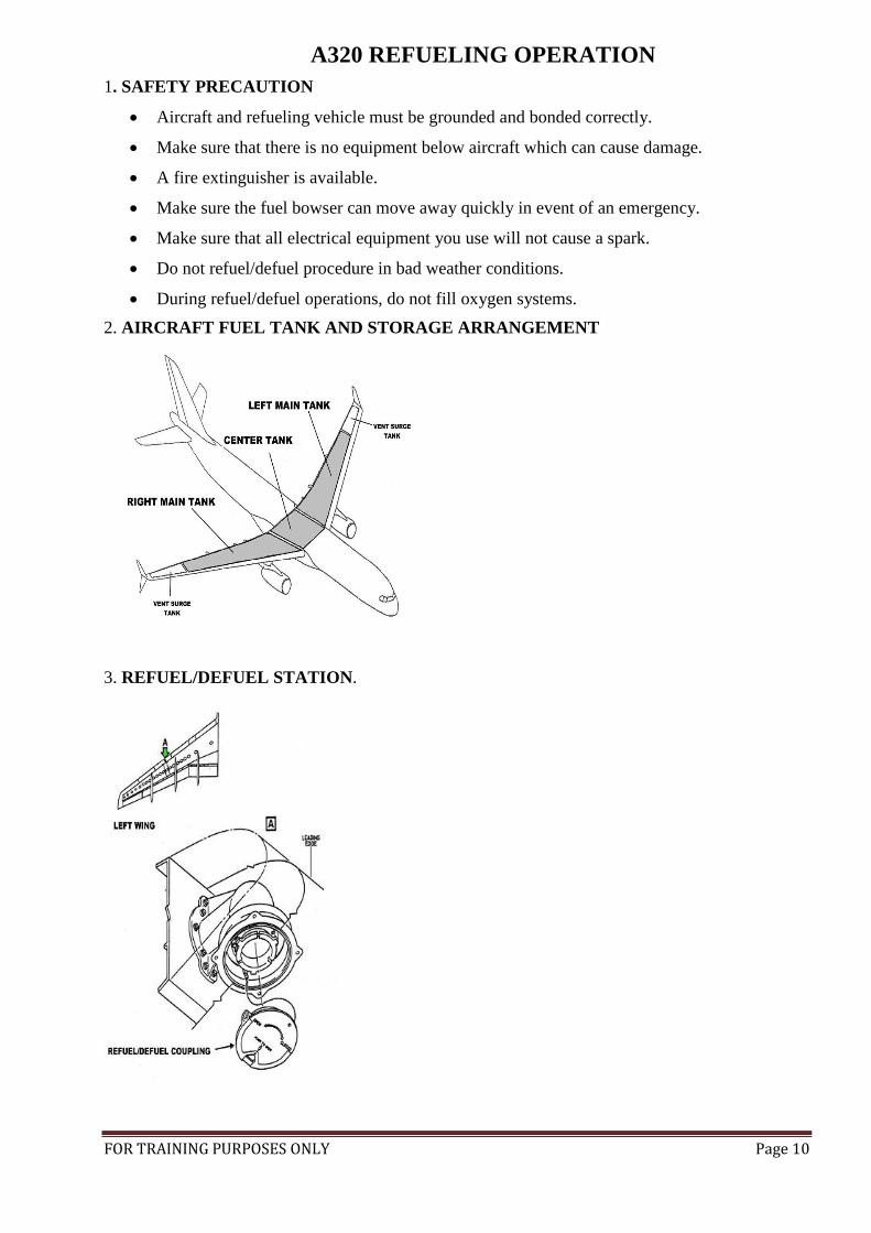
2. AIRCRAFT FUEL TANK AND STORAGE ARRANGEMENT
3. REFUEL/DEFUEL STATION.

FOR TRAINING PURPOSES ONLY Page 11
4. GROUNDING LOCATION AT MAIN LANDING GEAR DURING REFUELING/
DEFUELING
5. WATER CONTAMINATION CHECKS ON BOWSER:
This work must be carried out by CRS Holder or Pilot In Command. A fuel sample shall be
requested from the fuel supplier at commencement and completion of refueling. The fuel shall be
clear and water free. The check for water may be visually or by use of the fuel drain sample kit.
Water detector remains YELLOW if nil water is detected. Water detector turns BLUE when fuel is
contaminated with water.
FOR TRAINING PURPOSES ONLY Page 12
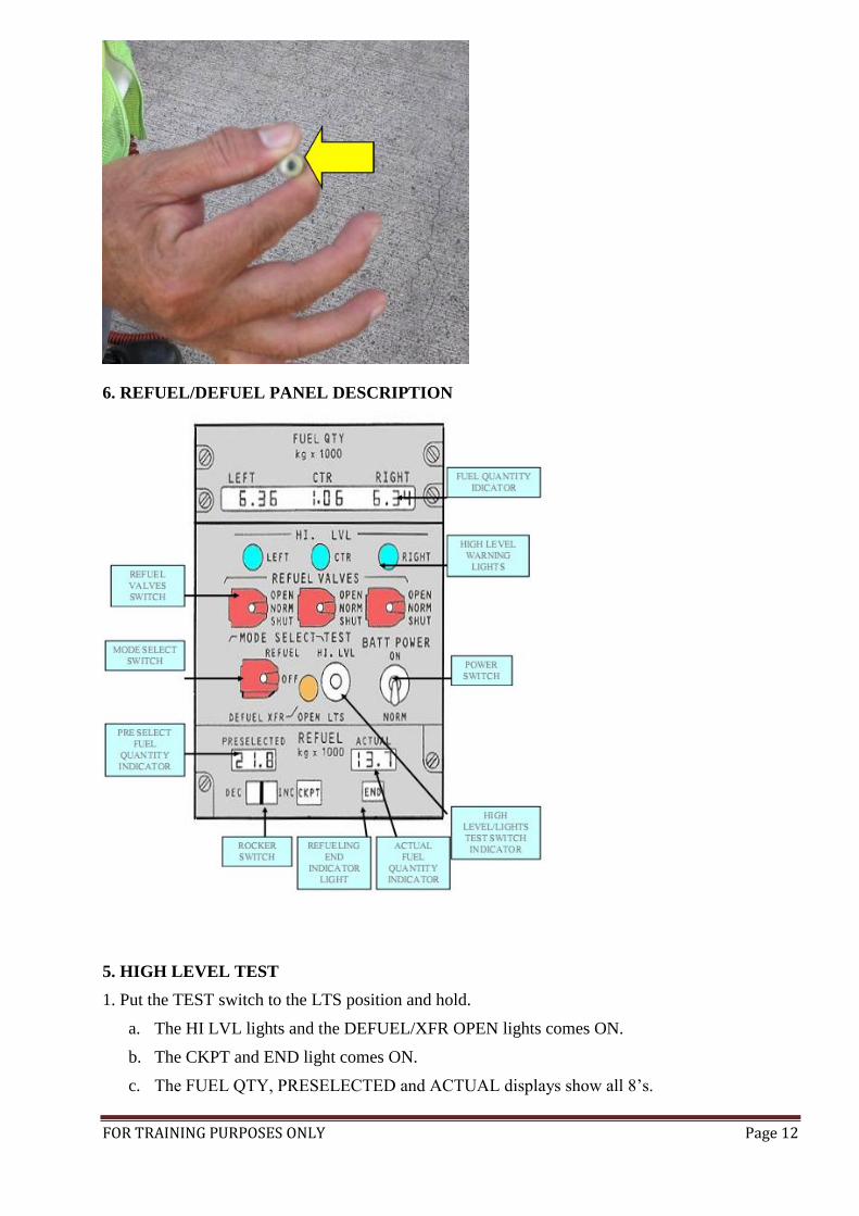
6. REFUEL/DEFUEL PANEL DESCRIPTION
5. HIGH LEVEL TEST
1. Put the TEST switch to the LTS position and hold.
a. The HI LVL lights and the DEFUEL/XFR OPEN lights comes ON.
b. The CKPT and END light comes ON.
c. The FUEL QTY, PRESELECTED and ACTUAL displays show all 8’s.

FOR TRAINING PURPOSES ONLY Page 13
2. Release the TEST switch.
a. The lights go back to their initial condition.
b. The FUEL QTY, PRESELECTED and ACTUAL displays back to their initial condition.
c. Put the TEST switch to the HI LVL position and hold.
d. If they were ON, they will come OFF. If they were OFF, they will come ON.
3. Release the TEST switch: The HI LVL lights go back to their initial condition.
6. PRESSURE REFUELING AUTOMATIC CONTROL
1. Perform a LTS and HI LVL test.
2. Make sure all refuel valves are in their NORM position.
3. Put the PRESELECTED rocker switch to the INC position and set to the required fuel load.
4. Put the MODE SELECT switch to the REFUEL position.
5. Start the pump from the bowser.
6. Make sure that the numbers on the ACTUAL display increases.
7. Make sure that the numbers on the FUEL QTY display increases.
8. When refueling operation is completed, the END light comes ON,
9. The numbers on the ACTUAL and PRESELECTED displays are stable and the same.
10. Stop the pump from the bowser.
CAUTION : If the tanks are full, the HI LVL lights comes ON.
7. PRESSURE REFUELING MANUAL CONTROL
1. Perform a LTS and HI LVL test.
2. Put the MODE SELECT switch to the REFUEL position.
3. Put REFUEL VALVES switch(es) for the applicable fuel tank(s) to the OPEN position.
4. Put REFUEL VALVES switch(es) for the fuel tank(s) which will not be refueled to the
SHUT position.
5. Start the pump from the bowser.
6. Make sure that the numbers on the ACTUAL and the FUEL QTY display increases.
7. Monitor the FUEL QTY displays.
8. When each tank has the correct fuel quantity, put its REFUEL VALVE switch to the SHUT
position.
9. Stop the pump from the bowser when refueling operation is complete.
10. Put MODE SELECT switch to the OFF position and guard it.
11. Put all REFUEL VALVES switches to the NORM position and guard it.
FOR TRAINING PURPOSES ONLY Page 14
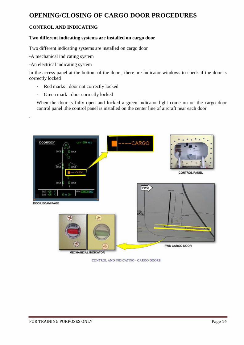
OPENING/CLOSING OF CARGO DOOR PROCEDURES
CONTROL AND INDICATING
Two different indicating systems are installed on cargo door
Two different indicating systems are installed on cargo door
-A mechanical indicating system
-An electrical indicating system
In the access panel at the bottom of the door , there are indicator windows to check if the door is
correctly locked
- Red marks : door not correctly locked
- Green mark : door correctly locked
When the door is fully open and locked a green indicator light come on on the cargo door
control panel .the control panel is installed on the center line of aircraft near each door
.

FOR TRAINING PURPOSES ONLY Page 15
FINAL DEPARTURE WALK AROUND CHECK LIST
GENERAL
The exterior inspection is primarily a visual check to ensure that the overall condition of the A/C,
the visible components and equipment are safe for the following flight.
OBSERVE AND MEMORIZE SLATS/FLAPS POSITION.
IF A L/G DOOR IS OPEN, OR IF SPOILERS ARE DEPLOYED, MAKE
CONTACT WITH MAINTENANCE BEFORE APPLYING HYDR. POWER.
CHECK STRUCTURE FOR NO IMPACT.

FOR TRAINING PURPOSES ONLY Page 16
1. LH FWD FUSELAGE
- AOA probe CONDITION
- Static port CLEAR
- Avionic ventilation inlet valve CHECK
- Left avionic compartment door CLOSED
- Oxygen overboard disch ind GREEN
2. NOSE SECTION
- Pitot probes CONDITION
- Static ports CLEAR
- TAT probes CONDITION
- Radome and latches CONDITION/LATCHED
- Forward avionic compartment door CLOSED
- Ground elec. pwr. door (if not rqrd.) CLOSED
3. NOSE L/G
- Nose wheel chocks AS REQUIRED
- Wheels and tires CONDITION
- Nose gear structure CONDITION
-Taxi, T.O., turn off lights CONDITION
- Proximity detectors CLEAN
- Hydraulic lines and CONDITION
- Wheelwell CHECK
- Safety pin AS REQUIRED
- L/G doors CLOSED
4. RH FWD FUSELAGE
- RH + AFT avionic compartment doors CLOSED
- Avionic ventilation overboard valve CONDITION
- Static port CLEAR
- AOA probes CONDITION
- Forward cargo door & service panel CHECK
5. LOWER CENTER FUSELAGE
- Antennas CONDITION
- Drain mast CONDITION

FOR TRAINING PURPOSES ONLY Page 17
- RAM air inlet flap CLOSED
- Ground air cond and eng start door CLOSED
- Anticollision light CHECK
- CTR TK fuel dripstick FLUSH
- Pack air intakes & outlets CLEAR
- Ground service cond. door CLOSED
- RAT door CLOSED
6. RH CENTER WING
- Refuel panel door CLOSED
- Fuel dripstick inner tank FLUSH
- Fuel water drain valve inner tank NO LEAK
- Landing lights CONDITION
- Wing leading edge ventilation intake CLEAR
- Slat 1 CONDITION
7. ENG 2 LH SIDE
- Cowl doors CLOSED/LATCHED
- Oil servicing access door CLOSED
- Drain mast CONDITION/NO LEAK
- Vent inlet CLEAR
- Engine inlet and fan blades CHECK
8. ENG 2 RH SIDE
- Anti ice exhaust CLEAR
- Compartment cooling exit CLEAR
- Pressure relief door CLOSED
- Starter valve access door CLOSED
- Turbine exhaust CLEAR
- Pylon/access panel CONDITION/CLOSED
9. RH WING LEADING EDGE
- Slats 2, 3, 4, 5 CONDITION
- Fuel dripstick inner and outer cells FLUSH
- Fuel water drain valves NO LEAK
(outer cell, surge tank)
- Refuel coupling CLOSED

FOR TRAINING PURPOSES ONLY Page 18
- Surge tank air inlet CLEAR
- Navigation light CONDITION
- Wing tip CONDITION
10. RH WING TRAILING EDGE
- Static dischargers CHECK
- Control surfaces CONDITION
- Flaps and fairings CONDITION
11. RH L/G AND FUSELAGE
- Chocks AS REQUIRED
- Wheels and tires CONDITION
- Brakes and brakes wear Ind. CONDITION
- Proximity sensors CLEAN
- Hydraulic lines CHECKS
- L/G structure CHECK
- Downlock spring CHECK
- Safety collar AS REQUIRED
- L/G doors CLOSED
- Hydraulic access door CLOSED
- Water drain mast CONDITION
12. RH AFT FUSELAGE
- Antennas CONDITION
- Cargo door and service panel CHECK
- Bulk door (optional) CHECK
- Toilet servicing access door CLOSED
- Outflow valve CONDITION
- Drain mast CONDITION
- Access door CLOSED
13. TAIL
- Stabilizer, elevator, fin and rudder CONDITION
- Static dischargers CHECK

FOR TRAINING PURPOSES ONLY Page 19
14. APU
- Access doors CLOSED
- Air intake CLEAR
- Drain and vents CONDITION/NO LEAK
- Oil cooler air outlet CLEAR
- Exhaust CLEAR
- Nav light CONDITION
15. LH AFT FUSELAGE
- Stabilizer, elevator, fin and rudder CONDITION
- Water filling and drainage CLOSED
- Hydraulic access door CLOSED
16. LH L/G
- Chocks AS REQUIRED
- Wheels and tires CONDITION
- Brakes and brakes wear ind CONDITION
- Proximity sensors CLEAN
- Hydraulic lines CHECK
- L/G structure CHECK
- Down lock springs CHECK
- Safety collar AS REQUIRED
- L/G doors CLOSED
17. LH WING TRAILING EDGE
- Flaps and fairing CONDITION
- Control surfaces CONDITION
- Static dischargers CHECK
18. LH WING LEADING EDGE
- Wing tip CONDITION
- Navigation light CONDITION
- Surge tank air inlet CLEAR
- Fuel water drain valves NO LEAK
(outer cell, surge tank)
FOR TRAINING PURPOSES ONLY Page 20
- Fuel dripstick inner and outer cell FLUSH
- Slats 2, 3, 4, 5 CONDITION
19. ENG 2 LH SIDE
- Cowl door CLOSED/LATCHED
- Oil servicing access door CLOSED
- Drain mast CONDITION/NO LEAK
- Vent inlet CLEAR
- Engine inlet and fan blades CHECK
20. ENG 2 RH SIDE
- Anti ice exhaust CLEAR
- Compartment cooling exit CLEAR
- Pressure relief door CLOSED
- Starter valve access door CLOSED
- Turbine exhaust CLEAR
- Pylon/access panel CONDITION/CLOSED
21. LH CENTER WING
- Slat 1 CONDITION
- Fuel water drain valves inner tank NO LEAK
- Fuel dripstick inner tank FLUSH
- Wing leading edge ventilation intake CLEAR
- Landing lights CONDITION