Embed Size (px)
Citation preview
OPERATING MANUAL
HEALTH AND SAFETY GUIDANCE NOTES
MODEL:B6FC
DATE :2001/06/29 VERSION:3.3

INDEX
1. OPERATING SAFETY PRECAUTIONS 1-1 1.1 OPERATING SAFETY PRECAUTIONS 1-1 1.2 MACHINE OPERATORS PRECAUTIONS 1-1 1.3 WARNING SIGNS AND MARKS ON THE MACHINE 1-2 1.4 SAFETY DEVICES AND INSPECTION 1-3
2. MACHINE SPECIFICATIONS 2-1 2.1 GENERAL DESCRIPTION 2-1 2.2 SPECIFICATION 2-1
3. NAMESS OF MACHINE PARTS 3-1 3.1 OUTLOOKING AND MAIN UNITS 3-1 3.2 HEAD STOCK 3-2
4. OPERATOR’S POSITION AND NOISE LEVEL 4-1 4.1 POSSITION AND NOISE EVEL 4-1 4.2 SPINDLE NOISE DETAIL 4-2
5. LUBRICATION 5-1 5.1 HEADSTOCK LUBRICATION 5-1 5.2 LUBICATION SYSTEM 5-2
6. INSTRUCTIONS IN OPERATIONS 6-1 6.1 HEAD STOCK 6-1
7. TRANSPORT, UNPACKING AND FLOOR SPACE 7-1 7.1 METHODS OF TRANSPORT 7-1 7.2 CAUTIONS FOR UNPACKING 7-1 7.3 FLOOR SPACE 7-3
8. TROUBLE SHOOTING 8-1 8.1 DISMANTLING OF MOTOR CAS HOWING 8-1 8.2 REPLACEMENT OF BELT 8-2
9. ADJUSTMENT OF PLAY BETWEEN GIBS 9-1 9.1 ADJUSSTMENT OF WORK TABLE GIBS 9-1 9.2 ADJASTMENT OF SADDLE GIB 9-1 9.3 ADJUSTMENT OF ELVEANTING GIB 9-2
INDEX
10. MAINTENANCE 10-1 10.1 DAILY MAINTENANCE 10-1 10.2 MONTHLY MAINTENANCE 10-1 10.3 QUARTERLY MAINTENANCE 10-1
11. PARTS LIST 11-1 11.1 HEAD STOCK UPSIDE (1) 11-1 11.2 HEAD STOCK UPSIDE (2) 11-3 11.3 HEAD STOCK INFRASTRUCTURE (1) 11-5 11.4 HEAD STOCK INFRASTRUCTURE (2) 11-7 11.5 HEAD STOCK INFRASTRUCTURE (3) 11-9 11.6 HEAD STOCK INFRASTRUCTURE (4) 11-11 11.7 COLUMN, BASE ASSEMBLY 11-13 11.8 COLUMN, BASE ASSEMBLY 11-15 11.9 ELEVANTING ASSEMBLY 11-17 11.10 Z AXIS ASSEMBLY 11-19 11.11 TABLE, SADDLE ASSEMBLY 11-21 11.12 TABLE, SADDLE (AXIS WITH HANDLE WHEEL) ASSEMBLY 11-23 11.13 X, Y AXIS ASSEMBLY 11-25 11.14 X, Y AXIS (WITH HANDLE WHEEL) ASSEMBLY 11-27 11.15 LUBRICATION, COOLINT ASSEMBLY 11-29
1. OPERATING SAFETY GUIDELINES 1.1 OPERATING SAFETY PRECAUTIONS a. The operator must be a technician who is trained in the operation and familiar with the manual. b. Never lay anything on the working surfaces of the machine, where it may foul with moving parts. c. Do not touch or reach over moving or rotating machine parts. d. Ensure you know how to stop the machine before starting it. e. Do not operate the machine in excess of its rated capacity. f. Do not wear rings, watches, ties or loose sleeved clothing. g. Stop machine immediately anything unexpected happens. h. Do not cutting Mg metal. i. Always select the correct tool for the job. j. Do not run the machine unattended. k. Do not place hand or body in path of moving objects. l. Know the function of each and every control.
m. Make sure power has been turned off when machine is unused for sometime.
n. Be sure spindle is not running when using gauges on the machine. o. Never take depth of cuts beyond machine's capability. 1.2 MACHINE OPERATORS PRECAUTIONS a. The machine is to be started or operated by an authorized operator only. b. Immediate stop and repair are needed in case of troubles in operations. c. In installation, the machine shall be connected to earth. d. In stop motion, the feed lever shall be placed in the neutral position. e. The machine should be stopped during the inspection on the work pieces. f. In clamping, check and ensure if the work pieces are firmly vise. g. The spindle must be kept clean and lubricated all the time. h. Do not place any tools on the work table to maintain its surface preciseness and smoothness. i. Prior to cutting, wait until the spindle is running steadily after the motor is stared. j. Use brush to clean off the iron fragments.
1-1
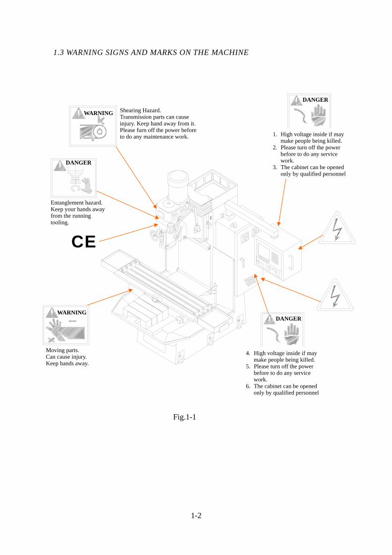
1.3 WARNING SIGNS AND MARKS ON THE MACHINE
1-2
Fig.1-1
CE
Shearing Hazard. Transmission parts can cause injury. Keep hand away from it. Please furn off the power before to do any maintenance work.
WARNING
Entanglement hazard. Keep your hands away from the running tooling.
DANGER
WARNING
Moving parts. Can cause injury. Keep hands away.
4. High voltage inside if may make people being killed.
5. Please turn off the power before to do any service work.
6. The cabinet can be opened only by qualified personnel
DANGER
1. High voltage inside if may make people being killed.
2. Please turn off the power before to do any service work.
3. The cabinet can be opened only by qualified personnel
DANGER
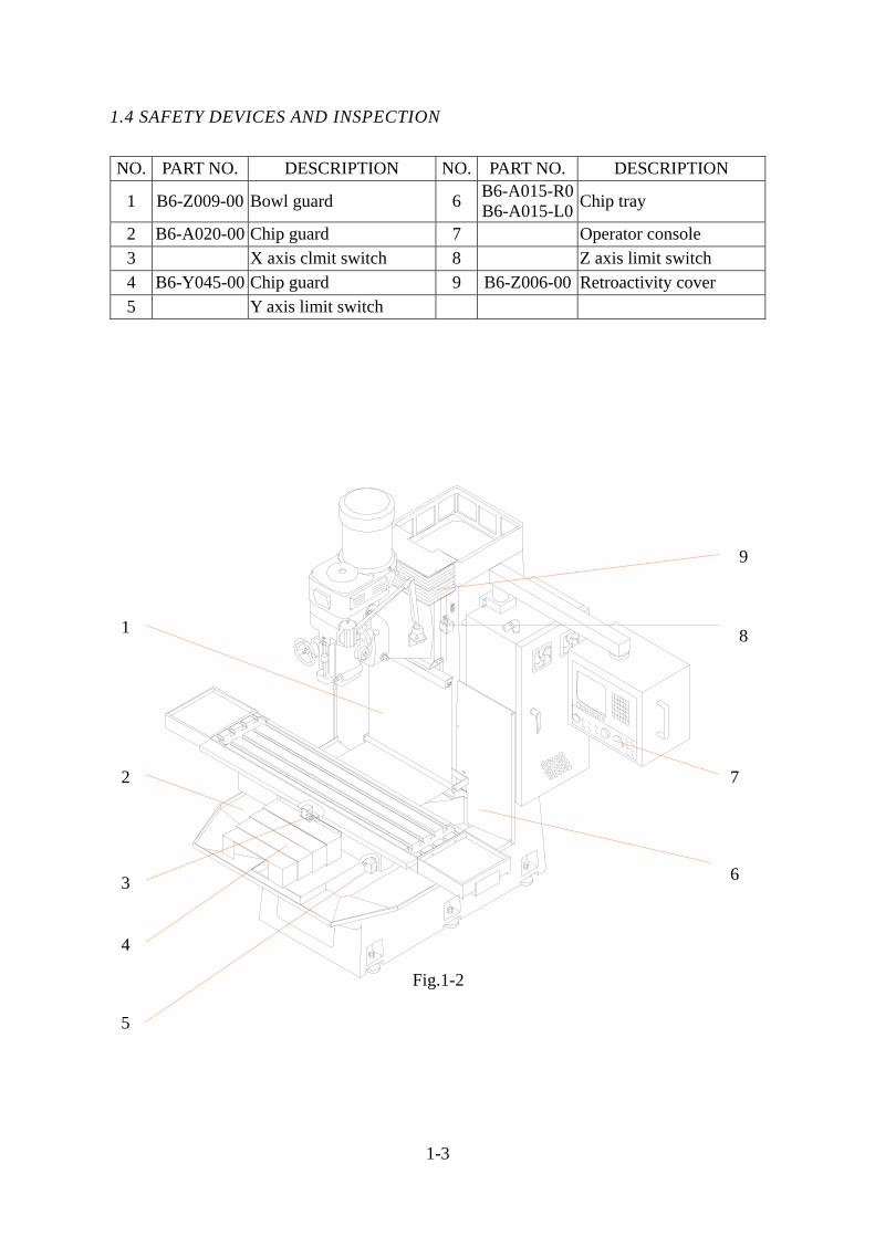
1.4 SAFETY DEVICES AND INSPECTION
NO. PART NO. DESCRIPTION NO. PART NO. DESCRIPTION
1 B6-Z009-00 Bowl guard 6 B6-A015-R0B6-A015-L0 Chip tray
2 B6-A020-00 Chip guard 7 Operator console 3 X axis clmit switch 8 Z axis limit switch 4 B6-Y045-00 Chip guard 9 B6-Z006-00 Retroactivity cover 5 Y axis limit switch
1-3
5
Fig.1-2
1
2
3
4
9
8
7
6
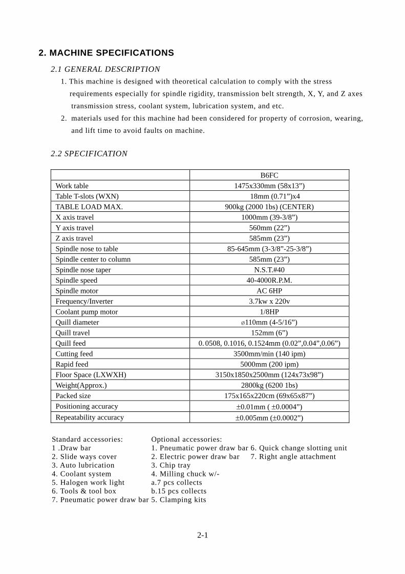
2. MACHINE SPECIFICATIONS
2.1 GENERAL DESCRIPTION 1. This machine is designed with theoretical calculation to comply with the stress requirements especially for spindle rigidity, transmission belt strength, X, Y, and Z axes transmission stress, coolant system, lubrication system, and etc. 2. materials used for this machine had been considered for property of corrosion, wearing, and lift time to avoid faults on machine. 2.2 SPECIFICATION
B6FC Work table 1475x330mm (58x13”) Table T-slots (WXN) 18mm (0.71”)x4 TABLE LOAD MAX. 900kg (2000 1bs) (CENTER) X axis travel 1000mm (39-3/8”) Y axis travel 560mm (22”) Z axis travel 585mm (23”) Spindle nose to table 85-645mm (3-3/8”-25-3/8”) Spindle center to column 585mm (23”) Spindle nose taper N.S.T.#40 Spindle speed 40-4000R.P.M. Spindle motor AC 6HP Frequency/Inverter 3.7kw x 220v Coolant pump motor 1/8HP Quill diameter ¿110mm (4-5/16”) Quill travel 152mm (6”) Quill feed 0. 0508, 0.1016, 0.1524mm (0.02”,0.04”,0.06”) Cutting feed 3500mm/min (140 ipm) Rapid feed 5000mm (200 ipm) Floor Space (LXWXH) 3150x1850x2500mm (124x73x98”) Weight(Approx.) 2800kg (6200 1bs) Packed size 175x165x220cm (69x65x87”) Positioning accuracy ±0.01mm ( ±0.0004”) Repeatability accuracy ±0.005mm (±0.0002”)
Standard accessories: 1 .Draw bar 2. Slide ways cover 3. Auto lubrication 4. Coolant system 5. Halogen work light 6. Tools & tool box 7. Pneumatic power draw bar
Optional accessories: 1. Pneumatic power draw bar 2. Electric power draw bar3. Chip tray4. Milling chuck w/- a.7 pcs collects b.15 pcs collects 5. Clamping kits
6. Quick change slotting unit7. Right angle attachment
2-1
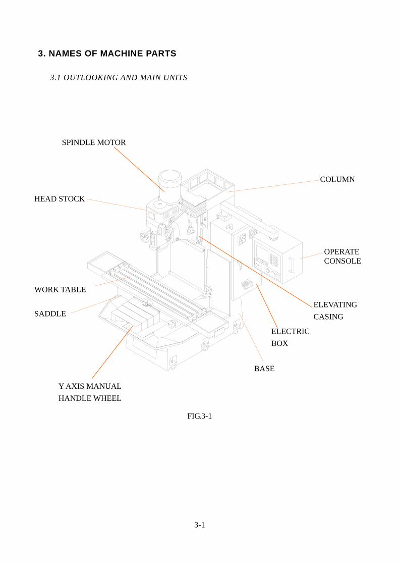
3. NAMES OF MACHINE PARTS 3.1 OUTLOOKING AND MAIN UNITS
FIG.3-1
3-1
HEAD STOCK
WORK TABLE
SADDLE
BASE
OPERATECONSOLE
COLUMN
SPINDLE MOTOR
Y AXIS MANUAL HANDLE WHEEL
ELECTRIC BOX
ELEVATING CASING
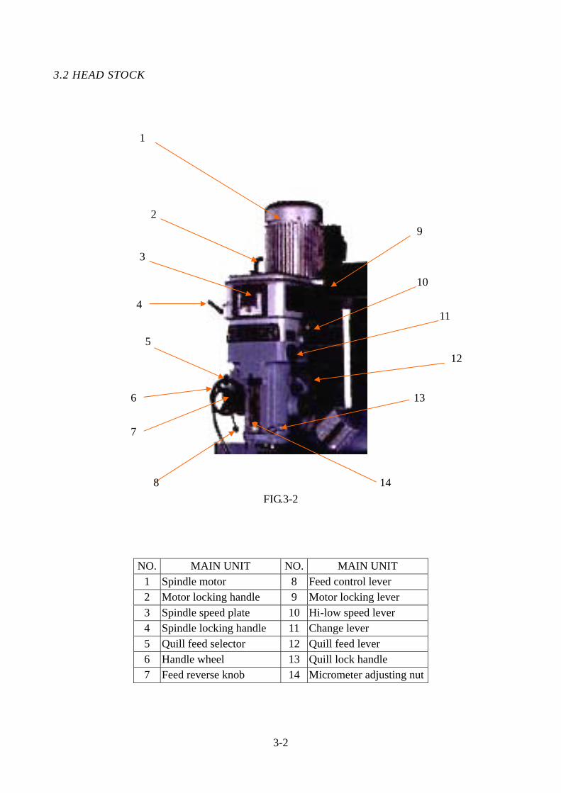
3.2 HEAD STOCK
FIG.3-2
NO. MAIN UNIT NO. MAIN UNIT
1 Spindle motor 8 Feed control lever 2 Motor locking handle 9 Motor locking lever 3 Spindle speed plate 10 Hi-low speed lever 4 Spindle locking handle 11 Change lever 5 Quill feed selector 12 Quill feed lever 6 Handle wheel 13 Quill lock handle 7 Feed reverse knob 14 Micrometer adjusting nut
3-2
1
12
11
10
5
4
3
2 9
6
8 14
7
13
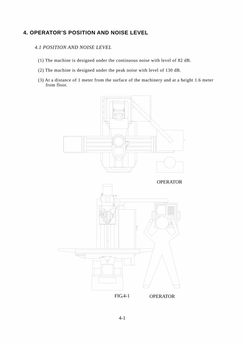
4. OPERATOR’S POSITION AND NOISE LEVEL
4.1 POSITION AND NOISE LEVEL (1) The machine is designed under the continuous noise with level of 82 dB. (2) The machine is designed under the peak noise with level of 130 dB.
(3) At a distance of 1 meter from the surface of the machinery and at a height 1.6 meter from floor.
FIG.4-1
4-1
OPERATOR
OPERATOR
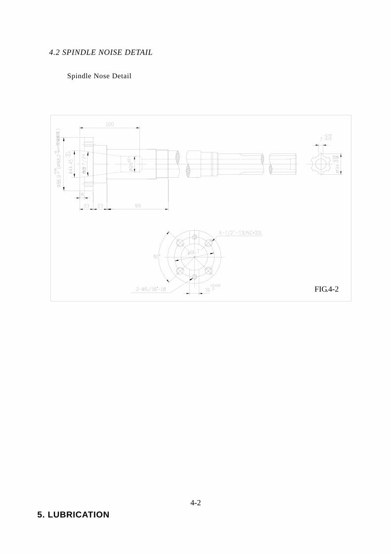
4.2 SPINDLE NOISE DETAIL Spindle Nose Detail
4-2 5. LUBRICATION
FIG.4-2
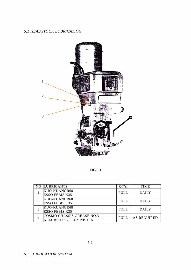
5.1 HEADSTOCK LUBRICATION
FIG.5-1
NO LUBRICANTS QTY. TIME
1 KUO-KUANGR68 ESSO FEBIS K35 FULL DAILY
2 KUO-KUANGR68 ESSO FEBIS K35 FULL DAILY
3 KUO-KUANGR68 ESSO FEBIS K35 FULL DAILY
4 COSMO CHASSIS GREASE NO.3 KLEUBER ISO FLEX-NBU 15 FULL AS REQUIRED
5-1
5.2 LUBRICATION SYSTEM
1
2
3
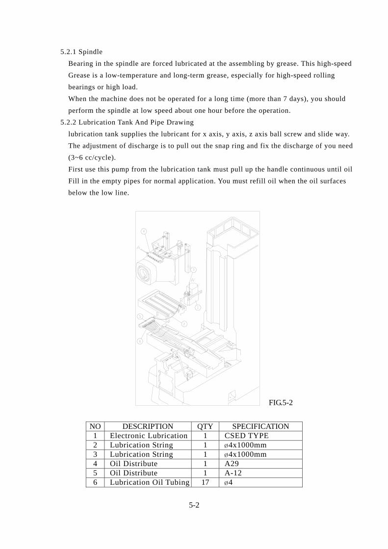
5.2.1 Spindle Bearing in the spindle are forced lubricated at the assembling by grease. This high-speed Grease is a low-temperature and long-term grease, especially for high-speed rolling bearings or high load. When the machine does not be operated for a long time (more than 7 days), you should perform the spindle at low speed about one hour before the operation. 5.2.2 Lubrication Tank And Pipe Drawing lubrication tank supplies the lubricant for x axis, y axis, z axis ball screw and slide way. The adjustment of discharge is to pull out the snap ring and fix the discharge of you need (3~6 cc/cycle). First use this pump from the lubrication tank must pull up the handle continuous until oil Fill in the empty pipes for normal application. You must refill oil when the oil surfaces below the low line.
NO DESCRIPTION QTY SPECIFICATION 1 Electronic Lubrication 1 CSED TYPE 2 Lubrication String 1 ¿4x1000mm 3 Lubrication String 1 ¿4x1000mm 4 Oil Distribute 1 A29 5 Oil Distribute 1 A-12 6 Lubrication Oil Tubing 17 ¿4
5-2
FIG.5-2
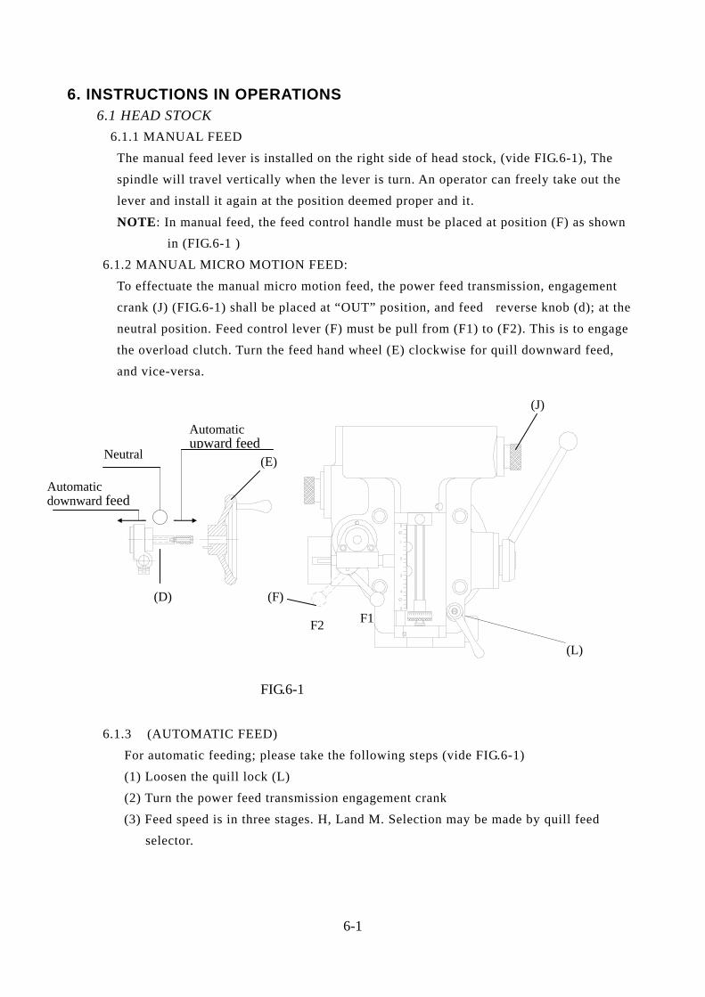
6. INSTRUCTIONS IN OPERATIONS 6.1 HEAD STOCK 6.1.1 MANUAL FEED The manual feed lever is installed on the right side of head stock, (vide FIG.6-1), The spindle will travel vertically when the lever is turn. An operator can freely take out the lever and install it again at the position deemed proper and it.
NOTE: In manual feed, the feed control handle must be placed at position (F) as shown in (FIG.6-1 ) 6.1.2 MANUAL MICRO MOTION FEED: To effectuate the manual micro motion feed, the power feed transmission, engagement crank (J) (FIG.6-1) shall be placed at “OUT” position, and feed reverse knob (d); at the neutral position. Feed control lever (F) must be pull from (F1) to (F2). This is to engage the overload clutch. Turn the feed hand wheel (E) clockwise for quill downward feed, and vice-versa.
6.1.3 (AUTOMATIC FEED) For automatic feeding; please take the following steps (vide FIG.6-1) (1) Loosen the quill lock (L) (2) Turn the power feed transmission engagement crank
(3) Feed speed is in three stages. H, Land M. Selection may be made by quill feed selector.
6-1
FIG.6-1
F2 F1
(J)
(D)
(L)
(F)
(E)
Automatic upward feed
Neutral
Automatic downward feed
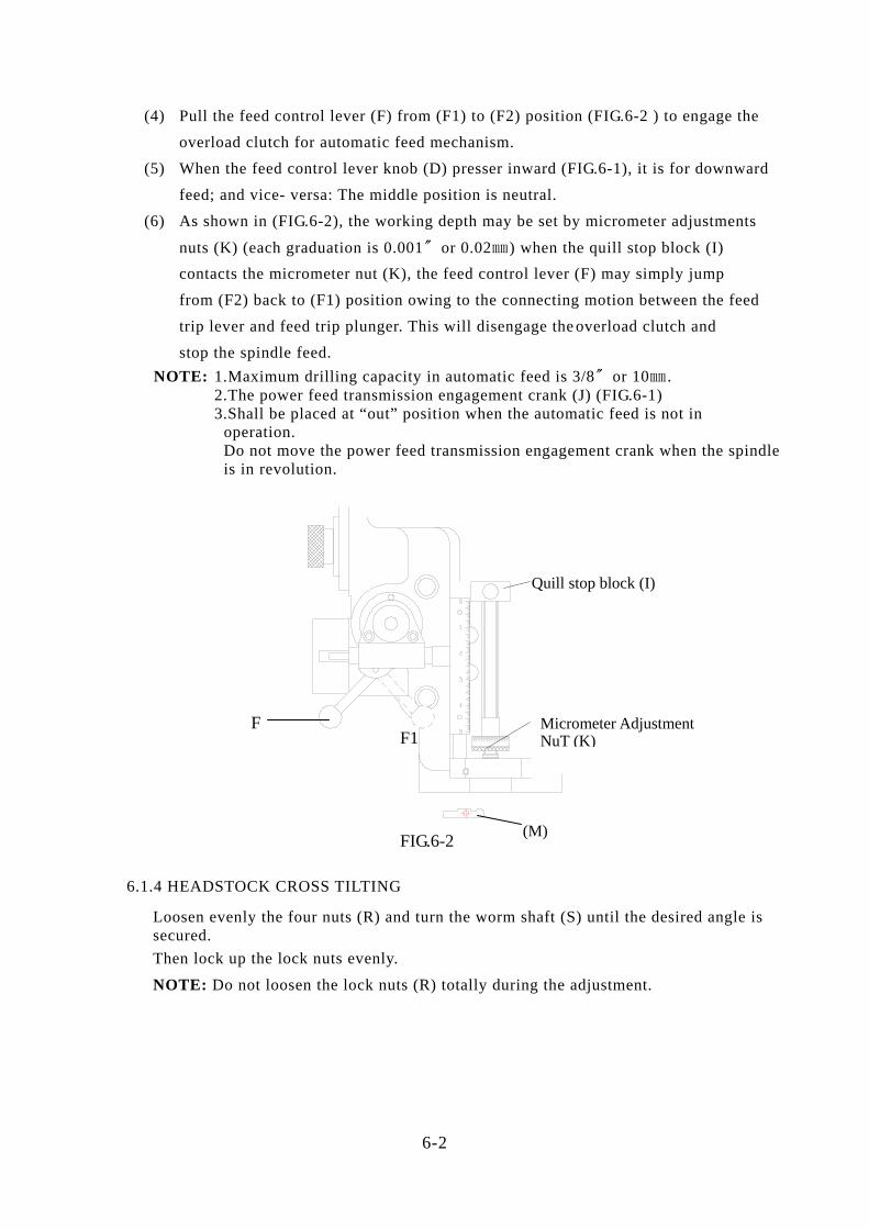
(4) Pull the feed control lever (F) from (F1) to (F2) position (FIG.6-2 ) to engage the overload clutch for automatic feed mechanism. (5) When the feed control lever knob (D) presser inward (FIG.6-1), it is for downward feed; and vice- versa: The middle position is neutral. (6) As shown in (FIG.6-2), the working depth may be set by micrometer adjustments
nuts (K) (each graduation is 0.001〞or 0.02㎜) when the quill stop block (I) contacts the micrometer nut (K), the feed control lever (F) may simply jump from (F2) back to (F1) position owing to the connecting motion between the feed trip lever and feed trip plunger. This will disengage the overload clutch and stop the spindle feed.
NOTE: 1.Maximum drilling capacity in automatic feed is 3/8〞or 10㎜ . 2.The power feed transmission engagement crank (J) (FIG.6-1) 3.Shall be placed at “out” position when the automatic feed is not in operation. Do not move the power feed transmission engagement crank when the spindle is in revolution.
6.1.4 HEADSTOCK CROSS TILTING
Loosen evenly the four nuts (R) and turn the worm shaft (S) until the desired angle is secured. Then lock up the lock nuts evenly.
NOTE: Do not loosen the lock nuts (R) totally during the adjustment.
6-2
(M)
F1F
Quill stop block (I)
Micrometer Adjustment NuT (K)
FIG.6-2
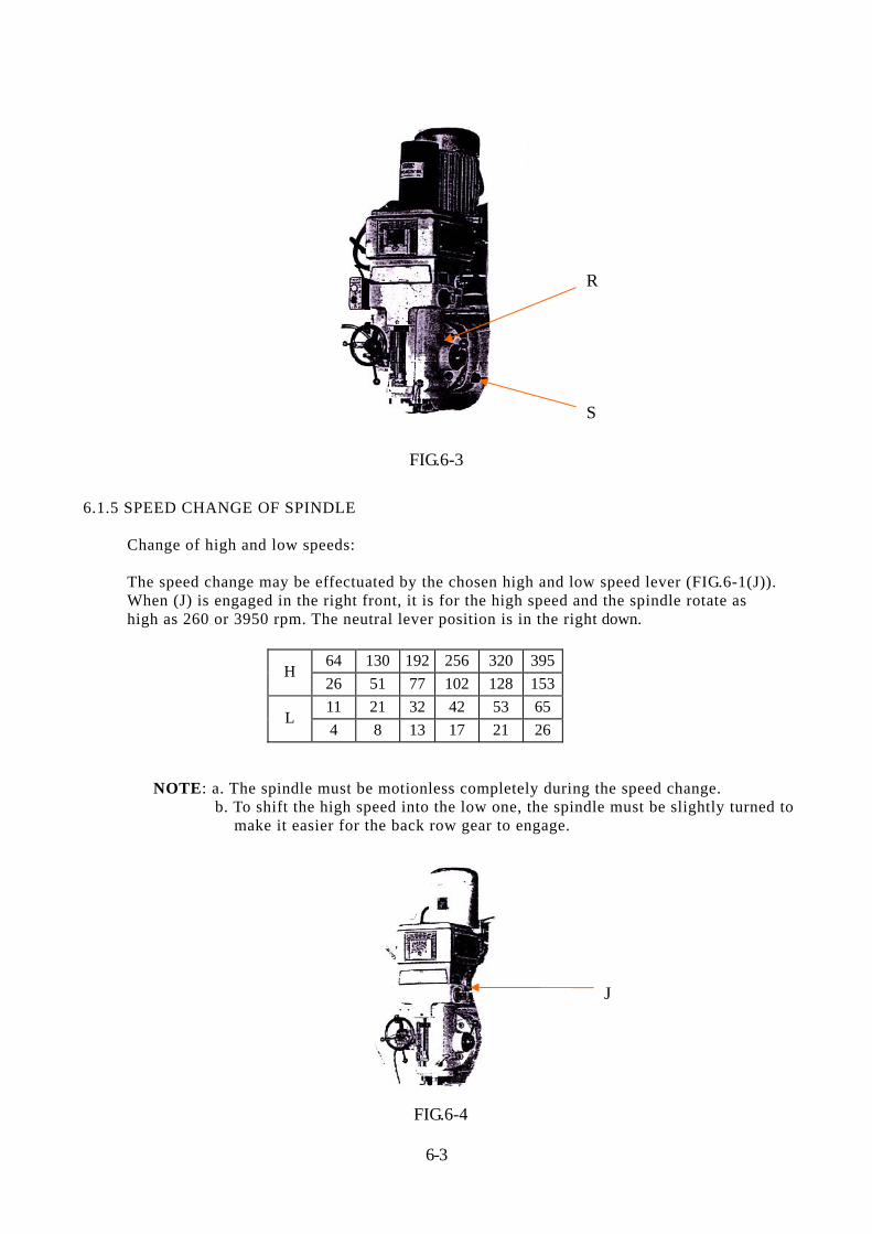
FIG.6-3
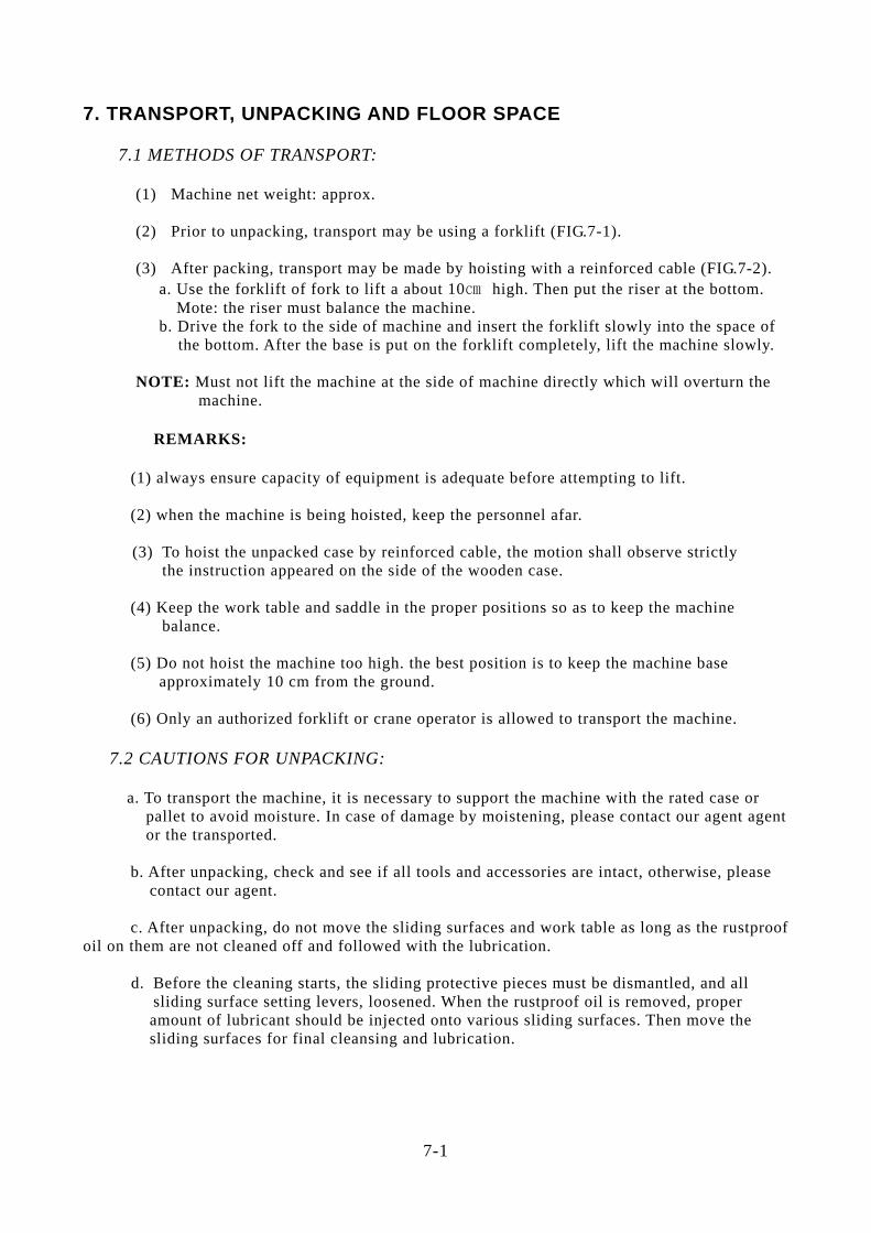
6.1.5 SPEED CHANGE OF SPINDLE Change of high and low speeds:
The speed change may be effectuated by the chosen high and low speed lever (FIG.6-1(J)). When (J) is engaged in the right front, it is for the high speed and the spindle rotate as high as 260 or 3950 rpm. The neutral lever position is in the right down.
64 130 192 256 320 395H
26 51 77 102 128 15311 21 32 42 53 65
L 4 8 13 17 21 26
NOTE: a. The spindle must be motionless completely during the speed change.
b. To shift the high speed into the low one, the spindle must be slightly turned to make it easier for the back row gear to engage.
FIG.6-4
6-3
R
S
J
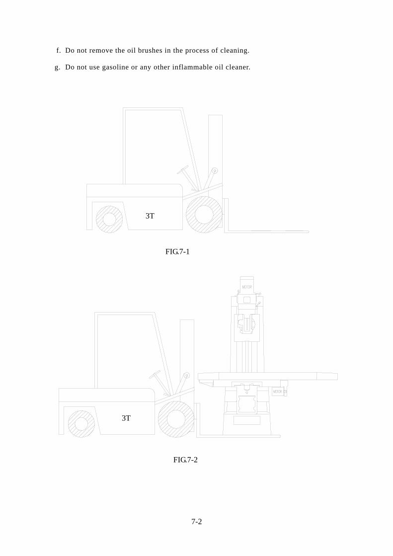
7. TRANSPORT, UNPACKING AND FLOOR SPACE 7.1 METHODS OF TRANSPORT: (1) Machine net weight: approx. (2) Prior to unpacking, transport may be using a forklift (FIG.7-1). (3) After packing, transport may be made by hoisting with a reinforced cable (FIG.7-2). a. Use the forklift of fork to lift a about 10㎝ high. Then put the riser at the bottom. Mote: the riser must balance the machine. b. Drive the fork to the side of machine and insert the forklift slowly into the space of the bottom. After the base is put on the forklift completely, lift the machine slowly. NOTE: Must not lift the machine at the side of machine directly which will overturn the machine. REMARKS: (1) always ensure capacity of equipment is adequate before attempting to lift. (2) when the machine is being hoisted, keep the personnel afar. (3) To hoist the unpacked case by reinforced cable, the motion shall observe strictly
the instruction appeared on the side of the wooden case.
(4) Keep the work table and saddle in the proper positions so as to keep the machine balance. (5) Do not hoist the machine too high. the best position is to keep the machine base approximately 10 cm from the ground. (6) Only an authorized forklift or crane operator is allowed to transport the machine. 7.2 CAUTIONS FOR UNPACKING:
a. To transport the machine, it is necessary to support the machine with the rated case or pallet to avoid moisture. In case of damage by moistening, please contact our agent agent or the transported.
b. After unpacking, check and see if all tools and accessories are intact, otherwise, please contact our agent. c. After unpacking, do not move the sliding surfaces and work table as long as the rustproof oil on them are not cleaned off and followed with the lubrication. d. Before the cleaning starts, the sliding protective pieces must be dismantled, and all sliding surface setting levers, loosened. When the rustproof oil is removed, proper amount of lubricant should be injected onto various sliding surfaces. Then move the sliding surfaces for final cleansing and lubrication.
7-1
f. Do not remove the oil brushes in the process of cleaning. g. Do not use gasoline or any other inflammable oil cleaner.
7-2
FIG.7-1
FIG.7-2
3T
3T
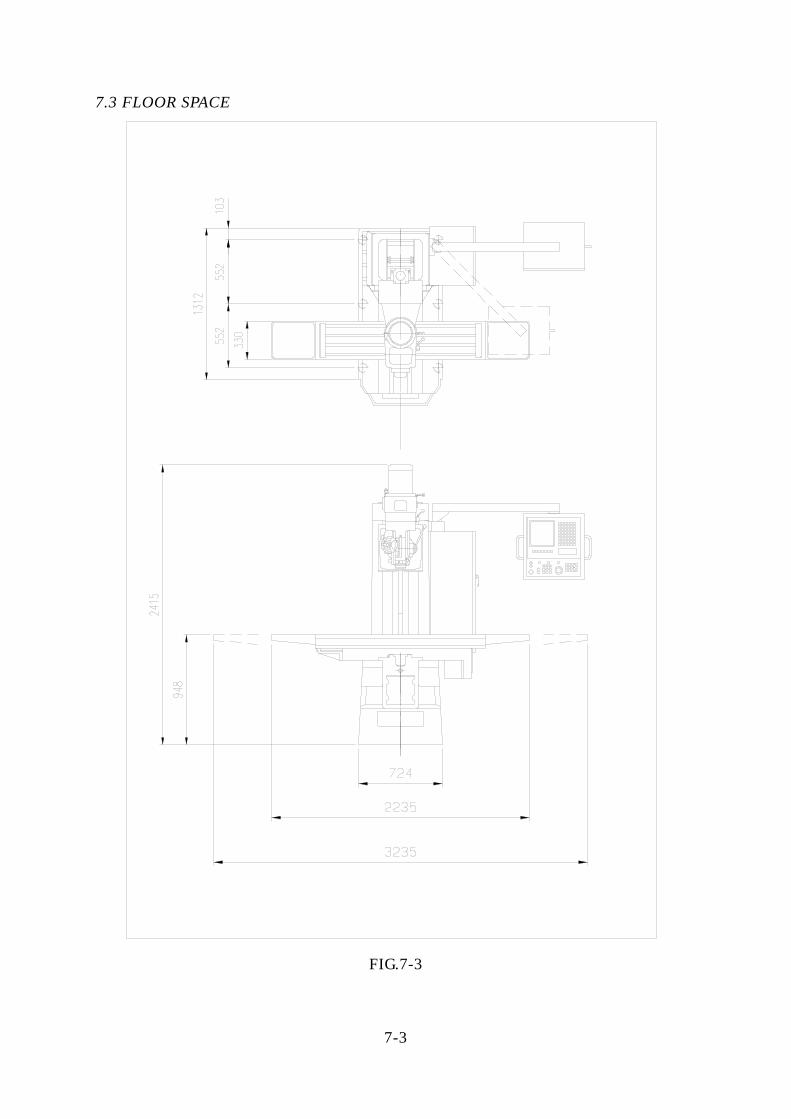
7.3 FLOOR SPACE
FIG.7-3
7-3
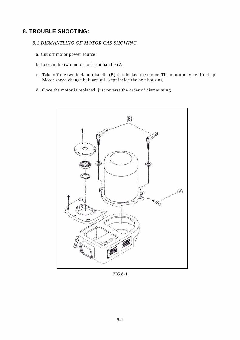
8. TROUBLE SHOOTING: 8.1 DISMANTLING OF MOTOR CAS SHOWING a. Cut off motor power source b. Loosen the two motor lock nut handle (A) c. Take off the two lock bolt handle (B) that locked the motor. The motor may be lifted up. Motor speed change belt are still kept inside the belt housing. d. Once the motor is replaced, just reverse the order of dismounting.
FIG.8-1
8-1
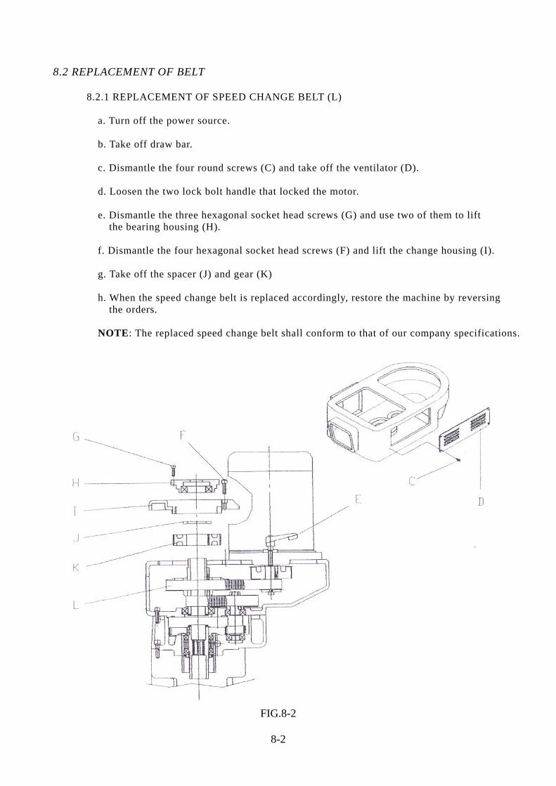
8.2 REPLACEMENT OF BELT 8.2.1 REPLACEMENT OF SPEED CHANGE BELT (L) a. Turn off the power source. b. Take off draw bar. c. Dismantle the four round screws (C) and take off the ventilator (D). d. Loosen the two lock bolt handle that locked the motor. e. Dismantle the three hexagonal socket head screws (G) and use two of them to lift the bearing housing (H). f. Dismantle the four hexagonal socket head screws (F) and lift the change housing (I). g. Take off the spacer (J) and gear (K) h. When the speed change belt is replaced accordingly, restore the machine by reversing the orders. NOTE: The replaced speed change belt shall conform to that of our company specifications.
FIG.8-2
8-2
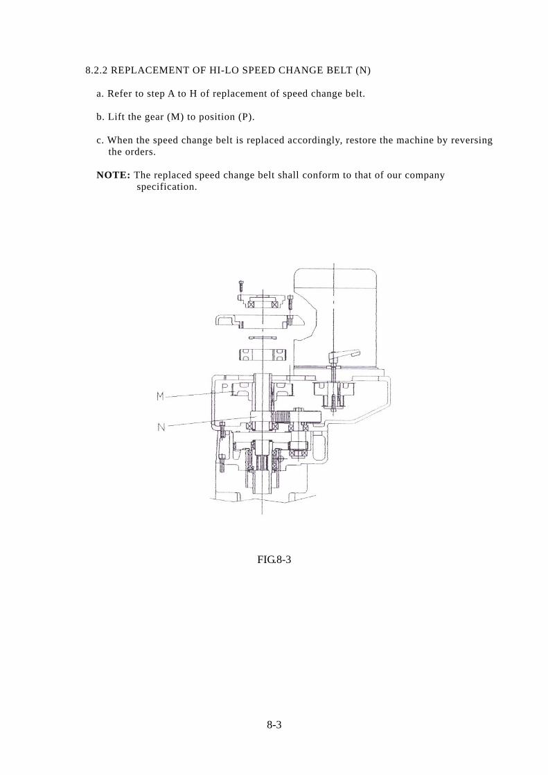
8.2.2 REPLACEMENT OF HI-LO SPEED CHANGE BELT (N) a. Refer to step A to H of replacement of speed change belt. b. Lift the gear (M) to position (P). c. When the speed change belt is replaced accordingly, restore the machine by reversing the orders. NOTE: The replaced speed change belt shall conform to that of our company specification.
FIG.8-3
8-3
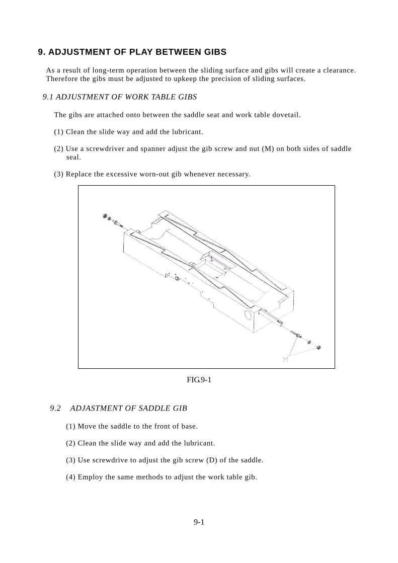
9. ADJUSTMENT OF PLAY BETWEEN GIBS As a result of long-term operation between the sliding surface and gibs will create a clearance. Therefore the gibs must be adjusted to upkeep the precision of sliding surfaces. 9.1 ADJUSTMENT OF WORK TABLE GIBS The gibs are attached onto between the saddle seat and work table dovetail.
(1) Clean the slide way and add the lubricant. (2) Use a screwdriver and spanner adjust the gib screw and nut (M) on both sides of saddle
seal. (3) Replace the excessive worn-out gib whenever necessary.
FIG.9-1
9.2 ADJASTMENT OF SADDLE GIB (1) Move the saddle to the front of base. (2) Clean the slide way and add the lubricant. (3) Use screwdrive to adjust the gib screw (D) of the saddle. (4) Employ the same methods to adjust the work table gib.
9-1
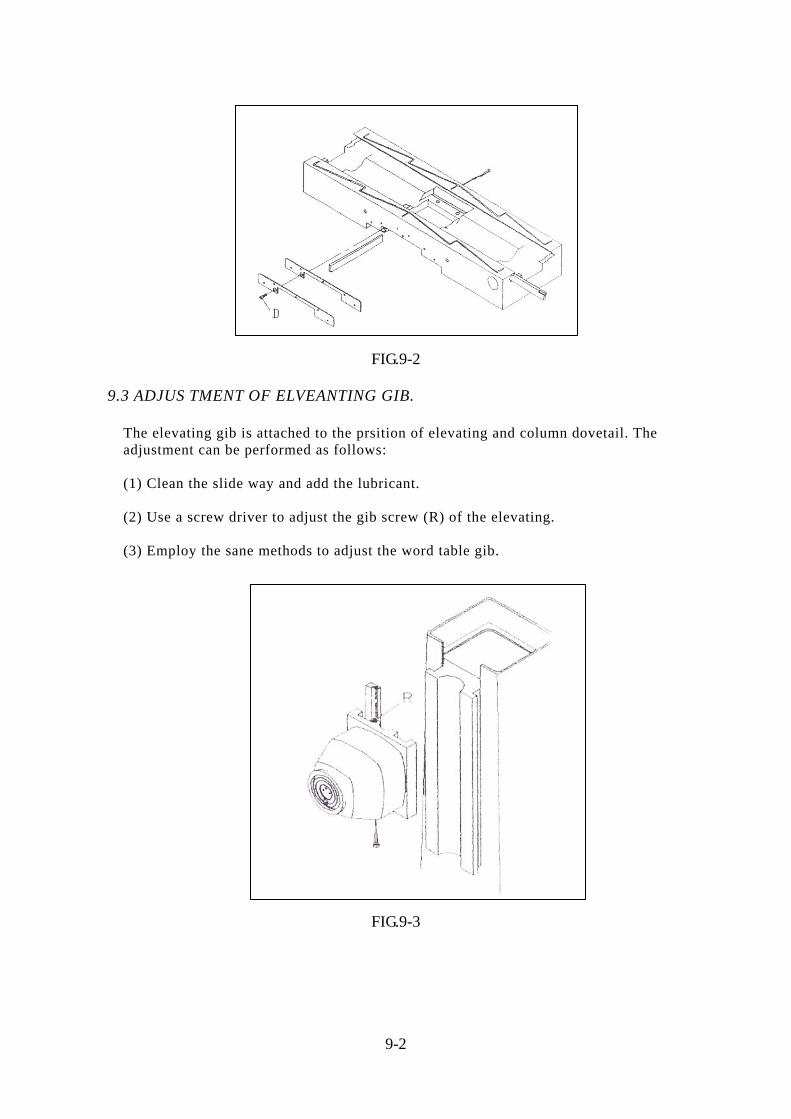
FIG.9-2 9.3 ADJUS TMENT OF ELVEANTING GIB. The elevating gib is attached to the prsition of elevating and column dovetail. The adjustment can be performed as follows: (1) Clean the slide way and add the lubricant. (2) Use a screw driver to adjust the gib screw (R) of the elevating. (3) Employ the sane methods to adjust the word table gib.
FIG.9-3
9-2
10. MAINTENANCE: "Maintenance is more important than repair; and repair is better than purchase". Under long-term operations, if the machine has not been properly maintained and operated, its service life shall be greatly reduced. The work piece quality is therefore affected, and the efficiency, decreased. it is essential for an operator to know how to handle the machine and the concept of its maintenance and keep correctly. 10.1DAILY MAINTENANCE: (1) Check and see if the oil level of oil pump is on the designated line. (2) The designated positions must be lubricated prior to operations . (3) Keep the machine idling for three to five minutes daily prior to operations.
(4) At the close of each day, work table shall be cleaned and the unfinished work piece must be removed. A little bit of lubricant is recommended.
(5) At the close of each day, all setting levers shall be loosened, and all sliding parts shall be move to the proper position. The cutter must be dismantled. (6) At the close of each day, the head stock must be restored to its normal position if it is tilted. 10.2 MONTHLY MAINTENANCE (1) Check and see if all clamping rails of various sliding surfaces are normal. (2) Check and see if the backlash between lead screw and its nut is normal. (3) Check and see if the quill lock and that of each and every sliding surface is normal. 10.3 QUARTERLY MAINTENANCE: (1) Check and see if the brake functions and belt are normal. (2) Inspect the level of work table and erection status of head stock. (3) Test the machine again by the chart of test specs. (4) Replace whatever parts worn-out.
10-1
11. PARTS LIST:
11-1
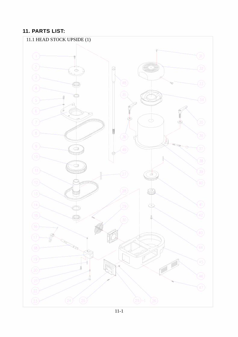
11.1 HEAD STOCK UPSIDE (1)
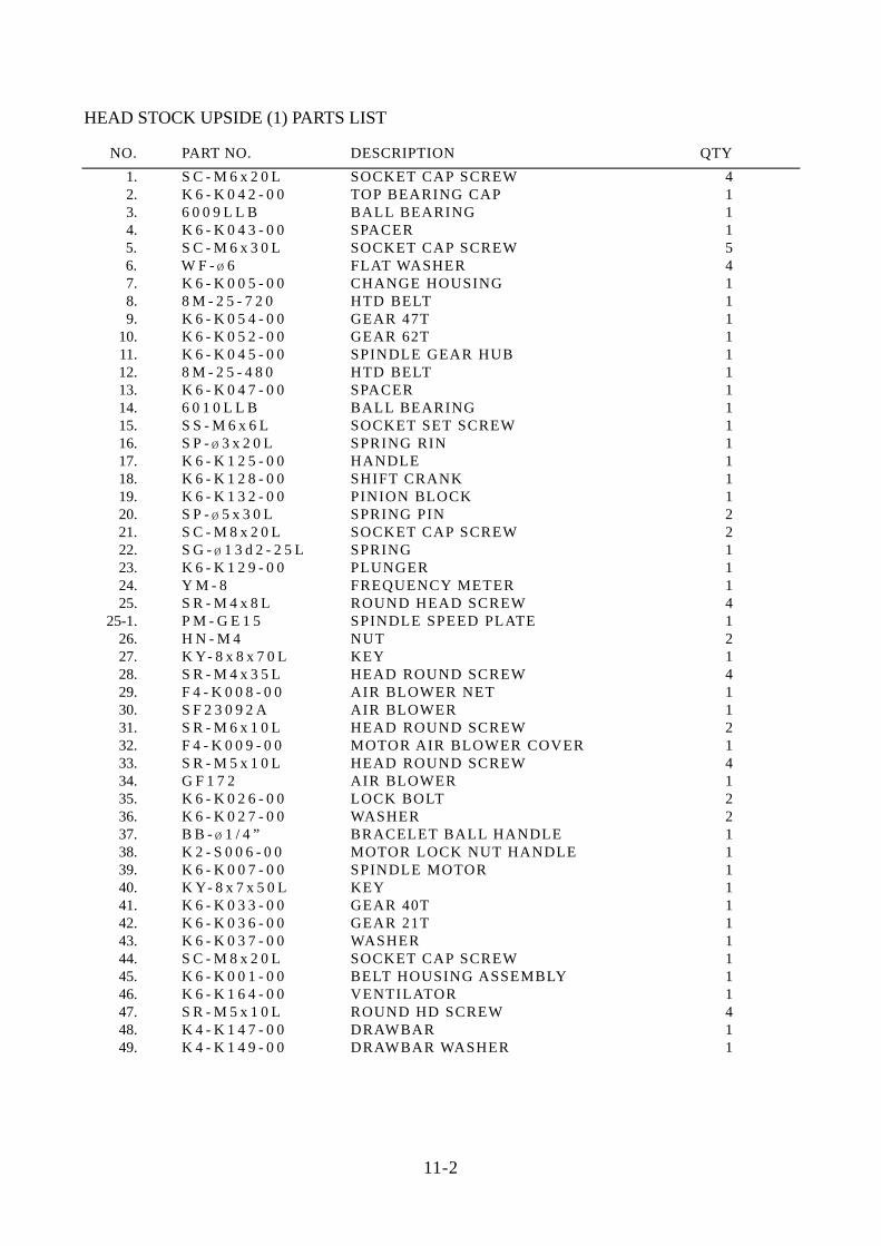
HEAD STOCK UPSIDE (1) PARTS LIST
NO. PART NO. DESCRIPTION QTY 1. S C - M 6 x 2 0 L SOCKET CAP SCREW 4 2. K 6 - K 0 4 2 - 0 0 TOP BEARING CAP 1 3. 6 0 0 9 L L B BALL BEARING 1 4. K 6 - K 0 4 3 - 0 0 SPACER 1
5. S C - M 6 x 3 0 L SOCKET CAP SCREW 5 6. W F - ¿ 6 FLAT WASHER 4
7. K 6 - K 0 0 5 - 0 0 CHANGE HOUSING 1 8. 8 M - 2 5 - 7 2 0 HTD BELT 1 9. K 6 - K 0 5 4 - 0 0 GEAR 47T 1
10. K 6 - K 0 5 2 - 0 0 GEAR 62T 1 11. K 6 - K 0 4 5 - 0 0 SPINDLE GEAR HUB 1 12. 8 M - 2 5 - 4 8 0 HTD BELT 1
13. K 6 - K 0 4 7 - 0 0 SPACER 1 14. 6 0 1 0 L L B BALL BEARING 1
15. S S - M 6 x 6 L SOCKET SET SCREW 1 16. S P - ¿ 3 x 2 0 L SPRING RIN 1 17. K 6 - K 1 2 5 - 0 0 HANDLE 1
18. K 6 - K 1 2 8 - 0 0 SHIFT CRANK 1 19. K 6 - K 1 3 2 - 0 0 PINION BLOCK 1
20. S P - ¿ 5 x 3 0 L SPRING PIN 2 21. S C - M 8 x 2 0 L SOCKET CAP SCREW 2
22. S G - ¿ 1 3 d 2 - 2 5 L SPRING 1 23. K 6 - K 1 2 9 - 0 0 PLUNGER 1
24. Y M - 8 FREQUENCY METER 1 25. S R - M 4 x 8 L ROUND HEAD SCREW 4
25-1. P M - G E 1 5 SPINDLE SPEED PLATE 1 26. H N - M 4 NUT 2
27. K Y- 8 x 8 x 7 0 L KEY 1 28. S R - M 4 x 3 5 L HEAD ROUND SCREW 4 29. F 4 - K 0 0 8 - 0 0 AIR BLOWER NET 1 30. S F 2 3 0 9 2 A AIR BLOWER 1 31. S R - M 6 x 1 0 L HEAD ROUND SCREW 2 32. F 4 - K 0 0 9 - 0 0 MOTOR AIR BLOWER COVER 1
33. S R - M 5 x 1 0 L HEAD ROUND SCREW 4 34. G F 1 7 2 AIR BLOWER 1
35. K 6 - K 0 2 6 - 0 0 LOCK BOLT 2 36. K 6 - K 0 2 7 - 0 0 WASHER 2 37. B B - ¿ 1 / 4 ” BRACELET BALL HANDLE 1 38. K 2 - S 0 0 6 - 0 0 MOTOR LOCK NUT HANDLE 1
39. K 6 - K 0 0 7 - 0 0 SPINDLE MOTOR 1 40. K Y- 8 x 7 x 5 0 L KEY 1
41. K 6 - K 0 3 3 - 0 0 GEAR 40T 1 42. K 6 - K 0 3 6 - 0 0 GEAR 21T 1
43. K 6 - K 0 3 7 - 0 0 WASHER 1 44. S C - M 8 x 2 0 L SOCKET CAP SCREW 1
45. K 6 - K 0 0 1 - 0 0 BELT HOUSING ASSEMBLY 1 46. K 6 - K 1 6 4 - 0 0 VENTILATOR 1 47. S R - M 5 x 1 0 L ROUND HD SCREW 4 48. K 4 - K 1 4 7 - 0 0 DRAWBAR 1 49. K 4 - K 1 4 9 - 0 0 DRAWBAR WASHER 1
11-2
11-3
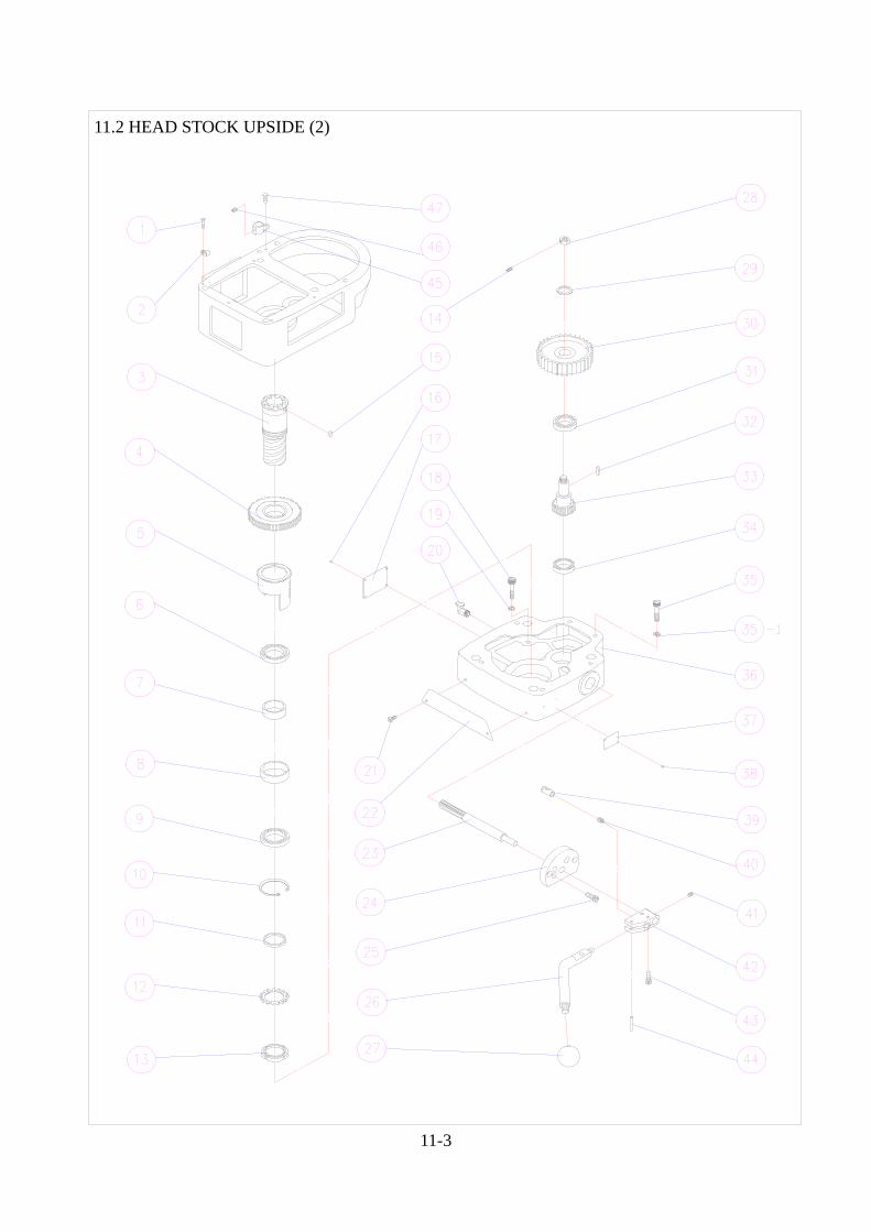
11.2 HEAD STOCK UPSIDE (2)
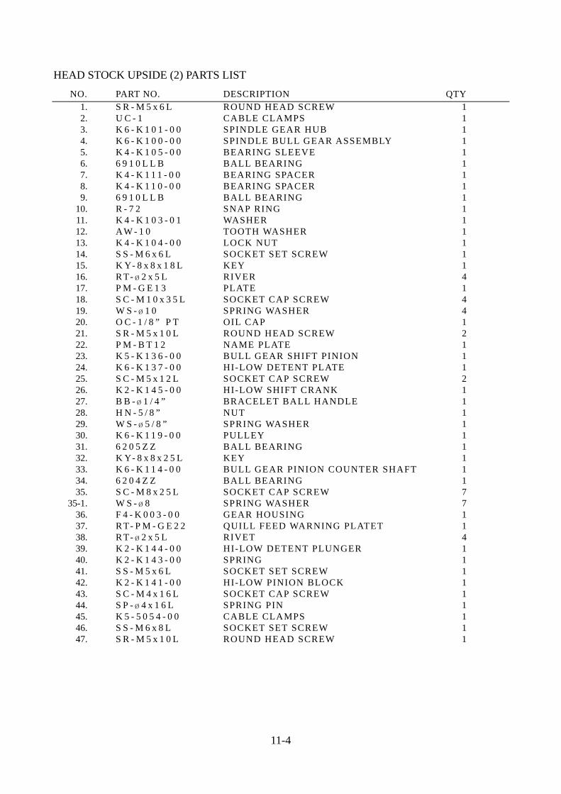
HEAD STOCK UPSIDE (2) PARTS LIST NO. PART NO. DESCRIPTION QTY 1. S R - M 5 x 6 L ROUND HEAD SCREW 1 2. U C - 1 CABLE CLAMPS 1
3. K 6 - K 1 0 1 - 0 0 SPINDLE GEAR HUB 1 4. K 6 - K 1 0 0 - 0 0 SPINDLE BULL GEAR ASSEMBLY 1 5. K 4 - K 1 0 5 - 0 0 BEARING SLEEVE 1 6. 6 9 1 0 L L B BALL BEARING 1 7. K 4 - K 1 1 1 - 0 0 BEARING SPACER 1 8. K 4 - K 1 1 0 - 0 0 BEARING SPACER 1 9. 6 9 1 0 L L B BALL BEARING 1 10. R - 7 2 SNAP RING 1 11. K 4 - K 1 0 3 - 0 1 WASHER 1
12. AW - 1 0 TOOTH WASHER 1 13. K 4 - K 1 0 4 - 0 0 LOCK NUT 1
14. S S - M 6 x 6 L SOCKET SET SCREW 1 15. K Y- 8 x 8 x 1 8 L KEY 1 16. R T- ¿ 2 x 5 L RIVER 4 17. P M - G E 1 3 PLATE 1 18. S C - M 1 0 x 3 5 L SOCKET CAP SCREW 4 19. W S - ¿ 1 0 SPRING WASHER 4 20. O C - 1 / 8 ” P T OIL CAP 1 21. S R - M 5 x 1 0 L ROUND HEAD SCREW 2 22. P M - B T 1 2 NAME PLATE 1
23. K 5 - K 1 3 6 - 0 0 BULL GEAR SHIFT PINION 1 24. K 6 - K 1 3 7 - 0 0 HI-LOW DETENT PLATE 1
25. S C - M 5 x 1 2 L SOCKET CAP SCREW 2 26. K 2 - K 1 4 5 - 0 0 HI-LOW SHIFT CRANK 1 27. B B - ¿ 1 / 4 ” BRACELET BALL HANDLE 1 28. H N - 5 / 8 ” NUT 1 29. W S - ¿ 5 / 8 ” SPRING WASHER 1 30. K 6 - K 1 1 9 - 0 0 PULLEY 1
31. 6 2 0 5 Z Z BALL BEARING 1 32. K Y- 8 x 8 x 2 5 L KEY 1
33. K 6 - K 1 1 4 - 0 0 BULL GEAR PINION COUNTER SHAFT 1 34. 6 2 0 4 Z Z BALL BEARING 1 35. S C - M 8 x 2 5 L SOCKET CAP SCREW 7
35-1. W S - ¿ 8 SPRING WASHER 7 36. F 4 - K 0 0 3 - 0 0 GEAR HOUSING 1
37. R T- P M - G E 2 2 QUILL FEED WARNING PLATET 1 38. R T- ¿ 2 x 5 L RIVET 4 39. K 2 - K 1 4 4 - 0 0 HI-LOW DETENT PLUNGER 1 40. K 2 - K 1 4 3 - 0 0 SPRING 1 41. S S - M 5 x 6 L SOCKET SET SCREW 1 42. K 2 - K 1 4 1 - 0 0 HI-LOW PINION BLOCK 1 43. S C - M 4 x 1 6 L SOCKET CAP SCREW 1 44. S P - ¿ 4 x 1 6 L SPRING PIN 1 45. K 5 - 5 0 5 4 - 0 0 CABLE CLAMPS 1 46. S S - M 6 x 8 L SOCKET SET SCREW 1 47. S R - M 5 x 1 0 L ROUND HEAD SCREW 1
11-4
11-5
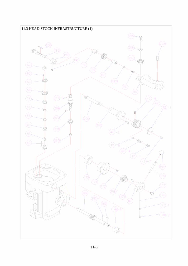
11.3 HEAD STOCK INFRASTRUCTURE (1)

HEAD STOCK INFRASTRUCTURE (1) PARTS LIST NO. PART NO. DESCRIPTION QTY 42. K 5 - A 0 4 2 - 0 0 SHIFTER CRANK 1 42-1. K 5 - A 0 4 2 - 1 0 PLATE 1 42-2. S C - M 5 x 1 2 L SOCKET CAP SCREW 1 42-3. S S - M 6 x 6 L SOCKET SET SCREW 1 42-4. K 5 - A 0 4 0 - 0 0 COMPRESSION SPRING 1 42-5. B S - ¿ 6 STEEL BALL 1 42-6. S S - M 6 x 1 0 L SOCKET SET SCREW 1 42-7. R T- ¿ 2 x 5 L RIVET 2 53. K 2 - A 0 5 3 - 0 0 FEED REVERSE BEVEL PINION 1 54. K 2 - A 0 5 4 - 0 0 BEVEL GEAR BEARING 1 55. K 2 - A 0 5 5 - 0 0 BEVEL GEAR THRUST WASHER 1 56. S - 1 6 SNAP RING 1 57. K 2 - A 0 5 7 - 0 0 FEED DRIVE CLUSTER GEAR (UPPER) 1 58. K 2 - A 0 5 8 - 0 0 FEED DRIVE CLUSTER GEAR (ENTER) 1 59. K 2 - A 0 5 9 - 0 0 FEED DRIVE CLUSTER GEAR 1 60. K Y- 3 x 3 x 4 5 L KEY 1 62. K 2 - A 0 6 2 - 0 0 TRIP SHAFT BUSHING 1 63. S S - M 4 x 1 0 L SOCKET SET SCREW 1 164. B B - 3 / 8 ” BLACK PLASTIC BALL HANDLE 1 165. K 2 - A 1 6 5 - 0 0 PINION SHAFT HUB HANDLE 1 166. K 2 - A 1 6 6 - 0 0 PINON SHAFT HUB 1 167. K 2 - A 1 6 7 - 0 0 PINION SHAFT HUB SCREW 1 168. K 2 - A 1 6 8 - 0 0 PINION SHAFT HUB SLEEVE 1 169. K Y- 3 x 3 x 1 8 L KEY 1 170. B S - ¿ 5 STEEL BALL 1 170-1. K 2 - A 1 7 0 - A 0 SPRING 1 170-2. S S - 5 / 1 6 ” x 5 / 1 6 ” SOCKET SET SCREW 1 171. K 2 - A 1 7 1 - 0 0 ROLL PIN 1 172. K 2 - A 1 7 2 - 0 0 SOCKET SET SCREW M5x10 2 173. K 4 - A 1 7 3 - 0 0 CLOCK SPRING 1 174. K 4 - A 1 7 4 - 0 0 SPRING COVER 1 176-A. K 4 - A 1 7 6 - 1 0 SHAFT BUSHING 1 182. K 4 - A 1 8 2 - 0 0 QUILL PINION SHAFT 1 182-1. K 2 - A 1 8 2 - A 0 PIN 1 191. S R - M 6 x 1 2 L ROUND HEAD SCREW 1
192. K 2 - A 1 9 2 - 0 0 BEVEL PINION WASHER 1 193. K 4 - A 1 9 3 - 0 0 FEED BEVEL PINION 1 195. S S - M 6 x 6 L SOCKET SET SCREW 1 196. K 4 - A 1 9 6 - 0 0 FEED WORM GEAR SHAFT SLEEVE 1 197. K 2 - A 1 9 7 - 0 0 WORM CRADLE BUSHING 1 198. K 4 - A 1 9 8 - 0 0 WORM GEAR SPACER 1 199. K 2 - A 1 9 9 - 0 0 FEED DRIVE WORM GEAR 1 200. K Y- 3 x 3 x 2 5 L KEY 1 202. K 4 - A 2 0 2 - 0 0 WORM GEAR CRADLE 1 203. K 2 - A 2 0 3 - 0 0 FEED ENGAGE PIN 1 206. K 5 - A 2 0 6 - 0 0 WORM GEAR CRADLE THROW-OUT 1 208. K 5 - A 2 0 8 - 0 0 SHIFT SLEEVE 1 215. S C - M 8 x 1 6 L SOCKET CAP SCREW 1 215-1. W S - ¿ 8 SPRING WASHER 1 216. W F - ¿ 5 / 6 ” FLAT WASHER 1 217. K 2 - A 2 1 7 - 0 0 FEED REVERSE BEVEL GEAR 1 217-1. K Y- 3 x 3 x 1 0 L KEY 1 218. K 5 - A 2 1 8 - 0 0 FEED DRIVING GEAR 1 221. K 2 - A 2 2 1 - 0 0 FEED DRIVE GEAR 1 222. K Y- 3 x 3 x 8 L KEY 1 223. B A - 6 6 TORRINGTON NEEDLE BEARING 1
11-6
11-7
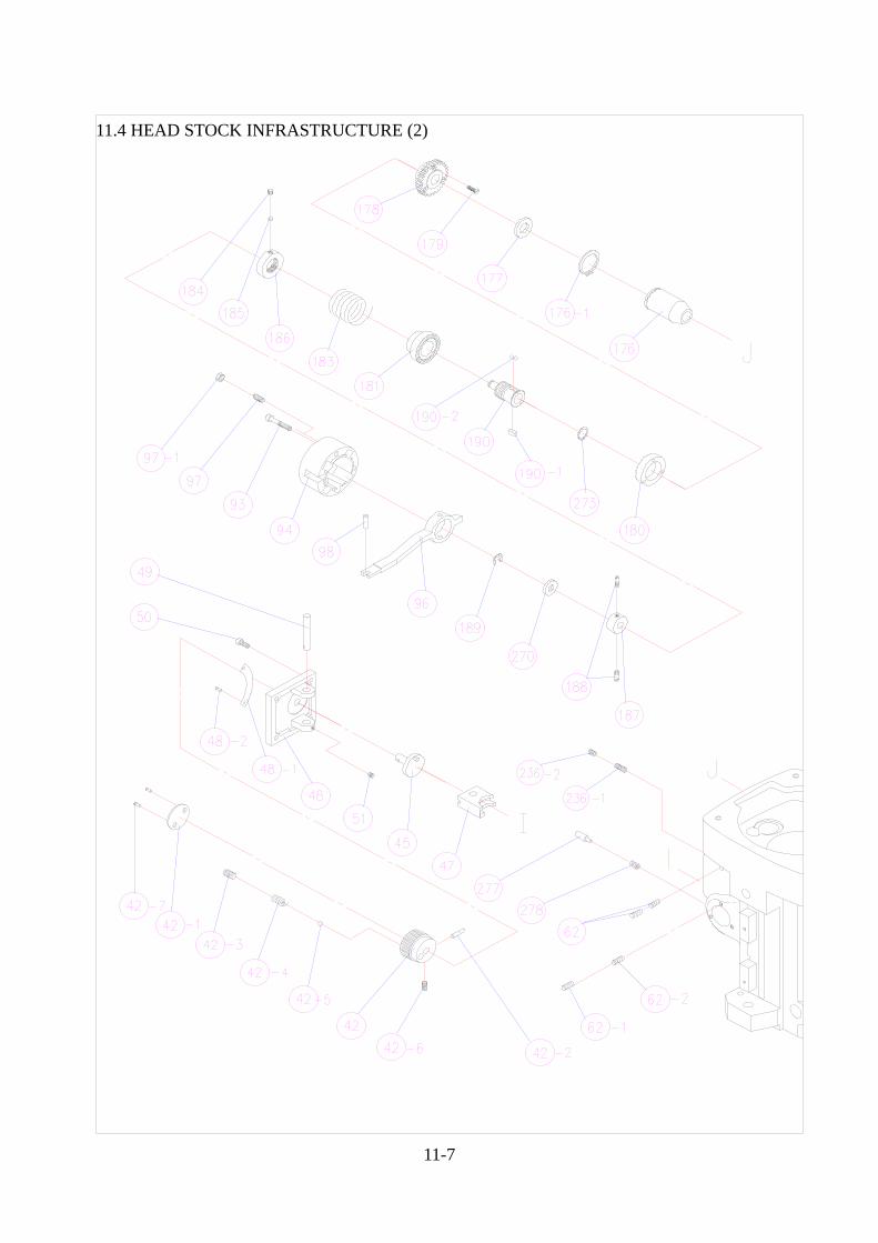
11.4 HEAD STOCK INFRASTRUCTURE (2)
HEAD STOCK INFRASTRUCTURE (2) PARTS LIST
NO. PART NO. DESCRIPTION QTY
42. K 5 - A 0 4 2 - 0 0 SHIFT CRANK 2 42-1. K 5 - A 0 4 2 - 1 0 NAME PLATE 1 42-2. S P - ¿ 3 x 3 0 L SPRING PIN 1 42-3. S S - M 6 x 6 L SOCKET SET SCREW 1 42-4. K 5 - A 0 4 2 - 4 0 COMPRESSION SPRING 1 42-5. B S - ¿ 6 STEEL BALL 1 42-6. S S - M 6 x 6 SET SCREW 1 42-7. R T- ¿ 2 x 5 L RIVET 2 45. K 5 - A 0 4 5 - 0 0 CLUSTER GEAR SHIFT CRANK 1 47. K 2 - A 0 4 7 - 0 0 FEED GEAR SHIFT FORK 1 48. K 4 - A 0 4 8 - 0 0 CLUSTER GEAR COVER 1 48-1. P M - G 2 6 QUILL FEED SPEED PLATE 1 48-2. R T- ¿ 2 x 5 L RIVET 2 49. K 2 - A 0 4 9 - 0 0 FEED SHIFT ROD 1 50. S C - M 5 x 1 5 L SOCKET CAP SCREW 4 51. S S - M 5 x 5 L SOCKET SET SCREW 1 62. S S - M 6 x 6 L SOCKET SET SCREW 2 62-1. S S - M 6 x 6 L SOCKET SET SCREW 1 62-2. S S - M 6 x 8 L SOCKET SET SCREW 1 93. S C - M 5 x 3 5 L SOCKET CAP SCREW 2 94. K 2 - A 0 9 4 - 0 0 CLUTCH ARM COVER 1 96. K 5 - A 0 9 6 - 0 0 OVERLOAD CLUTCH TRIP 1 97. 1 / 4 ” x 3 / 4 ” SOCKET SET SCREW 1 97-1. 1 / 4 ” NUT 1 98. S P - ¿ 5 x 1 6 L SPRING PIN 1 176. K 2 - A 1 7 6 - 0 0 QUILL PINON SHAFT BUSHING 1 176-1. K 2 - A 1 7 6 - A 0 SNAP RING S-32 1 177. K 2 - A 1 7 7 - 0 0 PINION SHAFT WORM GEAR SPACER 1 178. K 2 - A 1 7 8 - 0 0 OVERLOAD CLUTCH WORM GEAR 1 179. S R - M 4 x 1 3 L ROUND HEAD SCREW 3 180. K 2 - A 1 8 0 - 0 0 OVERLOAD CLUTCH RING 1 181. K 2 - A 1 8 1 - 0 0 OVERLOAK CLUTCH 1 183. K 2 - A 1 8 3 - 0 0 SAFETY CLUTCH SPRING 1 184. S S - M 6 x 6 L SOCKET SET SCREW 1 185. K 2 - A 1 8 5 - 0 0 SPACET 1 186. K 2 - A 1 8 6 - 0 0 OVERLOAD CLUTCH ADJUSTABLE NUT 1 187. K 2 - A 1 8 7 - 0 0 OVERLOAD CLUTCH RING 1 188. K 2 - A 1 8 8 - 0 0 OVERLOAD CLUTCH RING PIN 2 189. E - 8 SNAP RING 1 190. K 2 - A 1 9 0 - 0 0 OVERLOAD CLUTCH SLEEVE 1 190-1. K Y- 5 x 5 x 1 2 KEY 1 190-2. S B - ¿ 6 STEEL BALL SET SCREW 2 236-1. S S - M 6 x 1 0 L SOCKET SET SCREW 1 236-2. K 2 - A 2 3 6 - B 0 A236 SOCKET SET SCREW 1 270. K 2 - A 2 7 0 - 0 0 WASHER 1 273. S - 1 5 SNAP RING 1 277. K 2 - A 2 7 7 - 0 0 PIN 1 278. K 2 - A 2 7 8 - 0 0 COMPRESSION SPRING 1
11-8
11-9
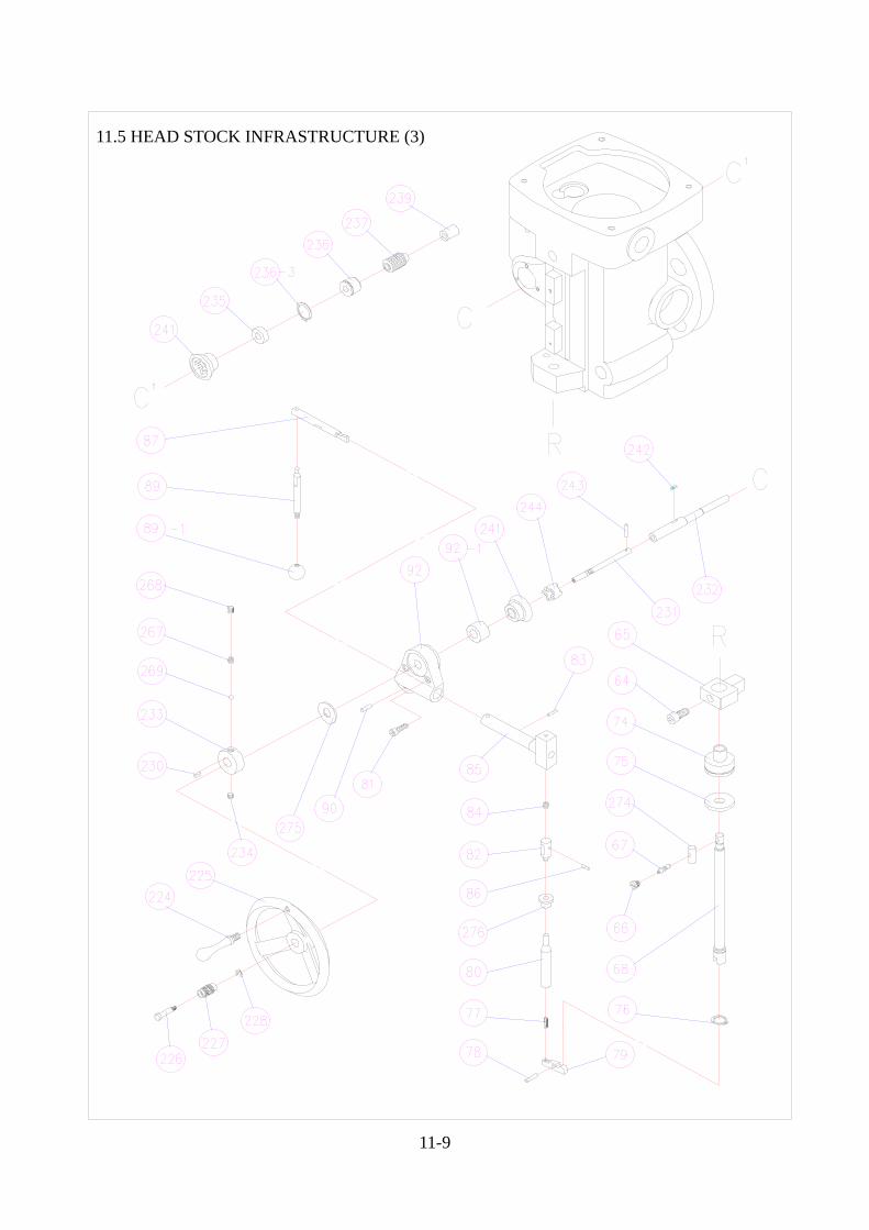
11.5 HEAD STOCK INFRASTRUCTURE (3)
HEAD STOCK INFRASTRUCTURE (3) PARTS LIST
NO. PART NO. DESCRIPTION QTY
64. S C - 3 / 8 ” x 3 / 4 ” SOCKET CAP SCREW 1 65. K 6 - A 0 6 5 - 0 0 QUILL STOP KNOB 1 66. K 2 - A 0 6 6 - 0 0 REVERSE TRIP BALL LEVER SCREW 1 67. K 2 - A 0 6 7 - 0 0 REVERSE TRIP BALL LEVER 1 68. K 5 - A 0 6 8 - I 0 QUILL STOP MICRO SCREW (IMPERIAL) 1 74. K 2 - A 0 7 4 - I 0 DIAL WITH 50 GRADUATIONS (IMPERIAL) 1 K 2 - A 0 7 4 - M 0 DIAL WITH 50 GRADUATIONS (METRIC) 1 75. K 2 - A 0 7 5 - I 0 QUILL DIAL STOP NUT (IMPERIAL) 1 K 2 - A 0 7 5 - M 0 QUILL DIAL STOP NUT (METRIC) 1 76. S E - 1 6 SNAP RING 1 77. S S - M 4 x 1 6 L SOCKET SET SCREW 1 78. K 2 - A 0 7 8 - 0 0 TRIP LEVER PIN 1 79. K 2 - A 0 7 9 - 0 0 FEED TRIP LEVER 1 80. K 2 - A 0 8 0 - 0 0 FEED TRIP PLUNGER 1 81. S C - M 6 x 2 0 L SOCKET CAP SCREW 2 82. K 2 - A 0 8 2 - 0 0 GEARSHIFT PLUNGER 1 83. S P - ψ 3 x 1 5 L SPRING PIN 1 84. K 2 - A 0 8 4 - 0 0 COMPRESSION SPRING 1 85. K 4 - A 0 8 5 - 0 0 FEED TRIP PLUNGER BUSHING 1 86. S P - ψ 3 x 1 2 L SPRING PIN 1 87. K 4 - A 0 8 7 - 0 0 CAM ROD 1 89. K 2 - A 0 8 9 - 0 0 TRIP HANDLE 1 89-1. B B - ψ 1 / 4 ” BLACK PLASTIC BALL HANDLE 1 90. K 2 - A 0 9 0 - 0 0 TRIP HANDLE PIN 1 92. K 2 - A 0 9 2 - 0 0 FEED TRIP BRACKET 1 92-1. K 5 - A 0 9 2 - 0 0 WASHER 1 224. K 2 - A 2 2 4 - 0 0 HANDWHEEL HANDLE 1 225. K 2 - A 2 2 5 - 0 0 HANDWHEEL 1 226. K 2 - A 2 2 6 - 0 0 FEED REVERSE KNOB STUD 1 227. K 2 - A 2 2 7 - 0 0 REVERSE KNOB 1 228. E S - 5 SNAP RING 1 230. K Y- 3 x 3 x 1 0 L KEY 1 231. K 6 - A 2 3 1 - 0 1 REVERSE CLUTCH ROD 1 232. K 6 - A 2 3 2 - 0 0 FEED WORM SHAFT 1 233. K 2 - A 2 3 3 - 0 0 HANDWHEEL CLUTCH 1 234. S S - M 6 x 6 L SOCKET SET SCREW 1 235. K 5 - A 2 3 5 - 0 0 FEED WORM SHAFT THRUST WASHER 1 236. K 2 - A 2 3 6 - 0 0 WORM SHAFT BUSHING 1 236-3. S - 2 2 SNAP RING 1 237. K 2 - A 2 3 7 - 0 0 WORM 1 239. K 2 - A 2 3 9 - 0 0 BUSHING 1 241. K 2 - A 2 4 1 - 0 0 FEED REVERSE BEVEL GEAR 2 242. K Y- 3 x 3 x 1 5 L KEY 1 243. S P - ψ 3 x 2 0 L PIN 1 244. K 2 - A 2 4 4 - 0 0 FEED REVERSE CLUTCH 1 267. K 2 - A 2 6 7 - 0 0 COMPRESSION SPRING 1 268. S S - M 8 x 6 L SOCKET SET SCREW 1 269. B S - ψ 3 / 1 6 ” STEEL BALL 1 274. K 2 - A 2 7 4 - 0 0 PIN 1 275. K 2 - A 2 7 5 - 0 0 WASHER 2 276. K 2 - A 2 7 6 - 0 0 TRIP PLUNGER BUSHING 1
11-10
11-11
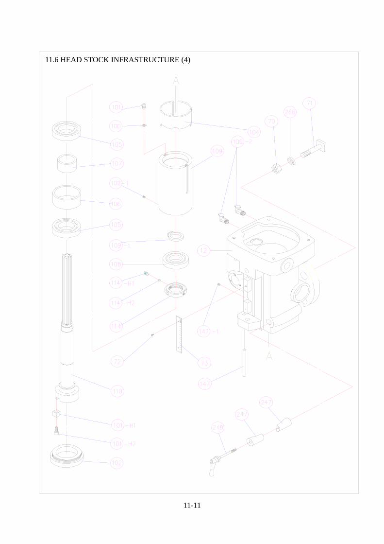
11.6 HEAD STOCK INFRASTRUCTURE (4)
HEAD STOCK INFRASTRUCTURE (4) PARTS LIST
NO. PART NO. DESCRIPTION QTY
12. F 4 - A 0 1 2 - 0 1 QUILL HOUSING 1 70. K 4 - A 0 7 0 - 0 0 HEX. NUT 4 71. K 5 - A 0 7 1 - 0 0 5/8”x65L T-BOLT 4 72. S R - M 3 x 4 L ROUND HEAD SCREW 2 73. K 5 - A 0 7 3 - I 0 MICROMETER SCALE (IMPERIAL) 1 K 5 - A 0 7 3 - M 0 MICROMETER SCALE (METRIC) 1 100. K 2 - A 1 0 0 - 0 0 WASHER 2 101. S R - M 5 x 8 L ROUND HEAD SCREW 2 101-H1. K 2 - A 1 1 0 - A 0 LOCK BLOCK 2 101-H2. S C - 5 / 1 6 ” x 5 / 8 ” SOCKET CAP SCREW 2 102. K 6 - A 1 0 2 - 0 0 #7207 NOSE-PIECE #40,R8 1 102-1. S C - M 5 x 6 L SET SCREW 1 104. K 6 - A 1 0 4 - 0 0 OIL BAFFLE 1 105. 7 2 1 0 B BEARING 2 106. K 5 - A 1 0 6 - 0 0 BUSHING 1 107. K 5 - A 1 0 7 - 0 0 BUSHING 1 108. 6 2 0 8 BEARING 1 109. K 6 - A 1 0 9 - 0 0 SLEEVE 1 109-1. S E - 4 0 SNAP RING 1 109-2. O C - 1 / 8 ” P T OIL CAP 1 110. K 6 - A 1 1 0 - 0 0 SPINDLE 1 114. K 5 - A 1 1 4 - 0 0 LOCK NUT 1 114-H1. S S - M 8 x 8 L SET SCREW 1 114-H2. K 2 - A 1 8 5 - 0 0 PRESSURE WASHER 1 147. K 2 - B 1 4 7 - 0 0 STOP PIN 1 147-1. S S - M 6 x 8 L SOCKET SET SCREW 1 247. K 5 - A 2 4 7 - 0 0 QUILL LOCK SLEEVE 1 248. K 4 - A 2 4 8 - 0 0 QUILL LOCK BOLT 1 266. K 4 - A 2 6 6 - 0 0 WASHER 4 11-12
11-13
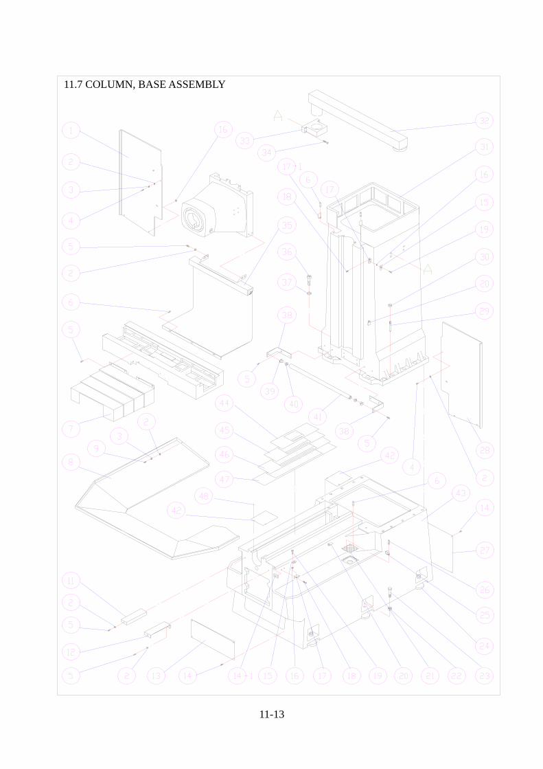
11.7 COLUMN, BASE ASSEMBLY
COLUMN, BASE ASSEMBLY PARTS LIST
NO. PART NO. DESCRIPTION QTY 1. B 6 - A 1 1 5 - L 0 CHIP GUARD 1 2. W F - ¿ 6 FLAT WASHER 18 3. W S - ¿ 6 SPRING WASHER 8 4. S B - M 6 x 8 L HEX. SOCKET BUTTON HEAD SCREW 4 5. S C - M 6 x 1 2 L SOCKET CAP SCREW 23 6. S R - M 5 x 1 0 L ROUND HEAD SCREW 6 7. B 6 - Y 0 4 5 - 0 0 CHIP GUARD 1 8. B 6 - A 1 2 0 - 0 1 CHIP TRAY 1 9. S B - M 6 x 1 2 L HEX. SOCKET BUTTON HEAD SCREW 4 11. B 6 - Y 0 4 6 - L 0 BRACKET 1 12. B 6 - Y 0 4 6 - R 0 BRACKET 1 13. B 6 - A 0 0 7 - 0 0 COVER 1 14. S R - M 6 x 6 L ROUND HEAD SCREW 8 14-1. B 6 - Y 0 1 8 - 0 0 STOP DOG 1 15. B 6 - X 0 1 9 - 0 1 DOG 2 16. H N - M 6 NUT 8 17. B 6 - X 0 1 6 - A 1 DOG 2 17-1. B 4 - Z 0 1 6 - 0 1 FIXED PLTE 2 18. S C - M 5 x 8 L SOCKET CAP SCREW 8 19. S C - M 5 x 1 2 L SOCKET CAP SCREW 4 20. B 6 - X 0 1 6 - 0 1 DOG 2 21. K 2 - C 1 3 0 - 0 0 STRAINER 2 22. H N - 3 / 4 ” NUT 6 23. S H - 3 / 4 ” x 3 ” ADJUSTING BOLT 6 24. K 5 - C 0 9 9 - 0 0 CHOCK 6 25. A C C - 6 CABLE CLAMPS 2 26. S R - M 6 x 1 0 L ROUND HEAD SCREW 2 27. B 6 - A 0 0 8 - 0 0 COVER 1 28. B 6 - A 1 1 5 - R 0 CHIP GUARD 1 29. D F - 6 0 0 4 - 0 0 TAPER PIN 2 30. H N - M 8 NUT 2 31. B 6 - A 0 0 1 - 0 0 COLUMN 1 32. B 6 - C 1 4 4 - 0 0 BOOM 1 33. B 6 - C 1 4 1 - A 1 BRACKET 1 34. S C - M 8 x 3 0 L SOCKET CAP SCREW 4 35. B 6 - Z 0 0 9 - 0 0 BOWL GUARD 1 36. S C - M 1 6 x 7 5 L SOCKET CAP SCREW 12 37. W S - ¿ 1 6 SPRING WASHER 12 38. B 6 - Z 0 4 2 - 0 0 BRACKET 2 39. B 6 - Z 0 4 1 - 0 0 PLUNGER 2 40. 6 0 9 Z Z BALL BEARING 2 41. B 6 - Z 0 4 0 - 0 0 BEAM 1 42. B 6 - Y 0 2 9 - A 1 COVER 2 43. B 6 - A 0 0 0 - 0 0 BASE 1 44. B 6 - Y 0 2 5 - 0 3 CHIP GUARD 1 45. B 6 - Y 0 2 6 - 0 3 CHIP GUARD 1 46. B 6 - Y 0 2 7 - 0 3 CHIP GUARD 1 47. B 6 - Y 0 2 8 - 0 3 CHIP GUARD 1 48. S P - ¿ 3 x 6 L SPRING PIN 4
11-14

11-15
11.8 COLUMN, BASE ASSEMBLY
COLUMN, BASE ASSEMBLY PARTS LIST
NO. PART NO. DESCRIPTION QTY 1. B 6 - A 1 1 5 - L 0 CHIP GUARD 1 2. W F - ¿ 6 FLAT WASHER 8 3. W S - ¿ 6 SPRING WASHER 8 4. S B - M 6 x 8 L HEX. SOCKET BUTTON HEAD SCREW 4 5. S C - M 6 x 1 2 L SOCKET CAP SCREW 30 6. S R - M 5 x 1 0 L ROUND HEAD SCREW 8 7. B 6 - Y 0 4 5 - 0 0 CHIP GUARD 1 8. B 6 - A 1 2 0 - 0 1 CHIP TRAY 1 9. S B - M 6 x 1 2 L HEX. SOCKET BUTTON HEAD SCREW 4 11. B 6 - Y 0 4 6 - L 0 BRACKET 1 12. B 6 - Y 0 4 6 - R 0 BRACKET 1 13. B 6 - A 0 0 7 - 0 0 COVER 1 14. S R - M 6 x 6 L ROUND HEAD SCREW 8 15. B 6 - X 0 1 9 - 0 1 DOG 2 16. H N - M 6 NUT 8 17. B 6 - X 0 1 6 - A 1 DOG 2 18. S C - M 5 x 8 L SOCKET CAP SCREW 8 19. S C - M 5 x 1 2 L SOCKET CAP SCREW 4 20. B 6 - X 0 1 6 - 0 1 DOG 2 21. K 2 - C 1 3 0 - 0 0 STRAINER 2 22. H N - 3 / 4 ” NUT 6 23. S H - 3 / 4 ” x 3 ” ADJUSTING BOLT 6 24. K 5 - C 0 9 9 - 0 0 CHOCK 6 25. A C C - 6 CABLE CLAMPS 2 27. B 6 - A 0 0 8 - 0 0 COVER 1 28. B 6 - A 1 1 5 - R 0 CHIP GUARD 1 29. D F - 6 0 0 4 - 0 0 TAPER PIN 2 30. H N - M 8 NUT 2 31. B 6 - A 0 0 1 - A 0 COLUMN 1 32. B 6 - C 1 4 4 - 0 0 BOOM 1 33. B 6 - C 1 4 1 - A 1 BRACKET 1 34. S C - M 8 x 3 0 L SOCKET CAP SCREW 4 35. B 6 - Z 0 0 6 - 0 0 RETRACTILITY COVER 1 36. S C - M 1 6 x 7 5 L SOCKET CAP SCREW 12 37. W S - ¿ 1 6 SPRING WASHER 12 38. B 6 - Z 0 1 8 - 0 0 RETRACTILITY COVER BRACKEY 2 39. B 6 - Y 0 4 7 - 0 0 CHIP GUARD 1 40. B 6 - Z 0 1 9 - 0 0 FIXED PLATE 1 41. B 6 - A 0 1 3 - A 1 COVER PLATE 1 42. B 4 - Z 0 1 6 - 0 1 FIXED PIECE 2 43. B 6 - A 0 0 0 - 0 0 BASE 1
11-16
11-17
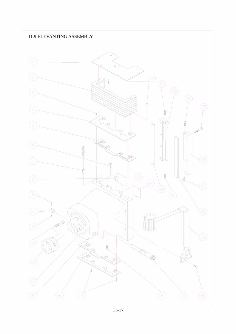
11.9 ELEVANTING ASSEMBLY
ELEVANTING ASSEMBLY PARTS LIST
NO PART NO DESCRIPTION QTY 1. B 6 - Z 0 0 5 - 0 0 FIXED PLATE 1 2. B 6 - Z 0 0 6 - 0 0 RETRACTILITY COVER 1 3. S R - M 5 x 1 0 L ROUND HEAD SCREW 12 4. B 6 - Z 0 0 7 - 0 1 WIPER HOLDER 1 5. B 6 - Z 0 1 4 - 0 0 WIPER 2 6. K 2 - C 0 4 1 - A 0 GIB ADJ-SCREW 2 7. B 6 - Z 0 0 8 - 0 0 BALANCING SCREW 2 8. B 6 - Z 0 2 2 - 0 0 GIB 1 9. S P - ¿ 5 x 3 0 L SPRING PIN 1 10. K 5 - C 0 0 7 - 0 0 SPACER 1 11. S S - M 6 x 8 L SOCKET SET SCREW 1 12. S C - M 1 0 x 9 0 L SOCKET CAR SCREW 4 13. K 5 - C 0 0 1 - 0 0 QUILL HOUSING ADJ-GEAR 1 14. B 6 - A 0 0 2 - 0 0 ELEVANTING CASTING 1 16. B 6 - Z 0 1 3 - 0 1 WIPER HOLDER 2 17. K 5 - C 0 0 6 - 0 0 WORM SHAFT 1 18. S C - M 6 x 1 2 L SOCKET CAP SCREW 4 19. W L - 1 2 V 5 5 W WORK LAMP 1 20. B 6 - Z 0 2 4 - 0 0 GIB 2 21. K 2 - C 0 4 1 - 0 0 GIB ADJ-SCREW 4 22. B 6 - Z 0 2 1 - 0 0 TURCITE 1 23. B 6 - Z 0 2 0 - 0 0 TURCITE 1 24. B 6 - Z 0 1 0 - 0 0 SLIDING RAIL 1 25. S C - M 1 0 x 4 0 L SOCKET CAP SCREW 8 26. B 6 - Z 0 1 1 - 0 0 SLIDING RAIL 1 27. S R - M 6 x 6 L ROUND HEAD SCREW 8
11-18
11-19
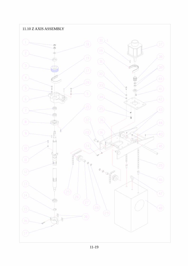
11.10 Z AXIS ASSEMBLY
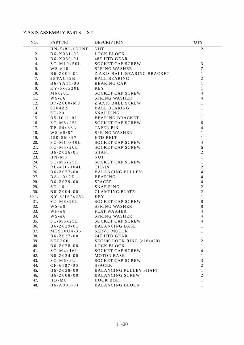
Z AXIS ASSEMBLY PARTS LIST
NO. PART NO. DESCRIPTION QTY 1. H N - 5 / 8 ” - 1 8 U N F NUT 2 2. B 6 - X 0 3 1 - 0 2 LOCK BLOCK 1 3. B 6 - X 0 3 0 - 0 1 48T HTD GEAR 1 4. S C - M 1 0 x 5 0 L SOCKET CAP SCREW 3 5. W S - ¿ 1 0 SPRING WASHER 7 6. B 6 - Z 0 0 1 - 0 1 Z AXIS BALL BEARING BRACKET 1 7. 2 5 TA C 6 2 B BALL BEARING 2 8. B 6 - YA 1 1 - 0 0 BEARING CAP 1 9. K Y- 6 x 6 x 2 0 L KEY 1 10. M 6 x 2 0 L SOCKET CAP SCREW 4 11. W S - ¿ 6 SPRING WASHER 4 12. B 7 - Z 0 0 0 - M 0 Z AXIS BALL SCREW 1 13. 6 2 0 4 Z Z BALL BEARING 1 14. S E - 2 0 SNAP RING 1 15. B 5 - I 0 1 1 - 0 1 BEARING BRACKET 1 16. S C - M 8 x 2 5 L SOCKET CAP SCREW 6 17. T P - # 4 x 3 8 L TAPER PIN 4 18. W S - ¿ 5 / 8 ” SPRING WASHER 1 19. 4 5 0 - 5 M x 2 7 HTD BELT 1 20. S C - M 1 0 x 4 0 L SOCKET CAP SCREW 4 21. S C - M 5 x 2 0 L SOCKET CAP SCREW 6 22. B 6 - Z 0 3 6 - 0 1 SHAFT 2 23. H N - M 6 NUT 1 24. S C - M 6 x 2 5 L SOCKET CAP SCREW 1 25. R L - 4 2 0 - 1 0 4 L CHAIN 2 26. B 6 - Z 0 3 7 - 0 0 BALANCING PULLEY 4 27. B A - 1 0 1 2 Z BEARING 4 28. B 6 - Z 0 3 9 - 0 0 SPACER 4 29. S E - 1 6 SNAP RING 2 30. B 6 - Z 0 0 4 - 0 0 CLAMPING PLATE 2 30-1. K Y- 3 / 1 6 ” x 2 5 L KEY 1 31. S C - M 8 x 2 0 L SOCKET CAP SCREW 8 32. W S - ¿ 8 SPRING WASHER 8 33. W F - ø 8 FLAT WASHER 4 34. W S - ø 6 SPRING WASHER 4 35. S C - M 6 x 2 5 L SOCKET CAP SCREW 4 36. B 6 - Z 0 2 9 - 0 1 BALANCING BASE 1 37. M T S 3 0 U 4 - 3 6 SERVO MOTOR 1 38. B 6 - Z 0 2 7 - 0 0 24T HTD GEAR 1 39. S E C 3 0 0 SEC300 LOCK RING ( ¿ 16x ¿ 20) 2 40. B 6 - Z 0 2 8 - 0 0 LOCK BLOCK 1 41. S C - M 4 x 1 6 L SOCKET CAP SCREW 4 42. B 6 - Z 0 3 4 - 0 0 MOTOR BASE 1 43. S C - M 6 x 8 L SOCKET CAP SCREW 3 44. C F - 6 1 0 7 - 0 0 SPACER 2 45. B 6 - Z 0 3 8 - 0 0 BALANCING PULLEY SHAFT 1 46. B 6 - Z 0 0 8 - 0 0 BALANCING SCREW 2 47. H B - M 8 HOOK BOLT 1 48. B 6 - A 0 0 5 - 0 1 BALANCING BLOCK 1
11-20
11-21
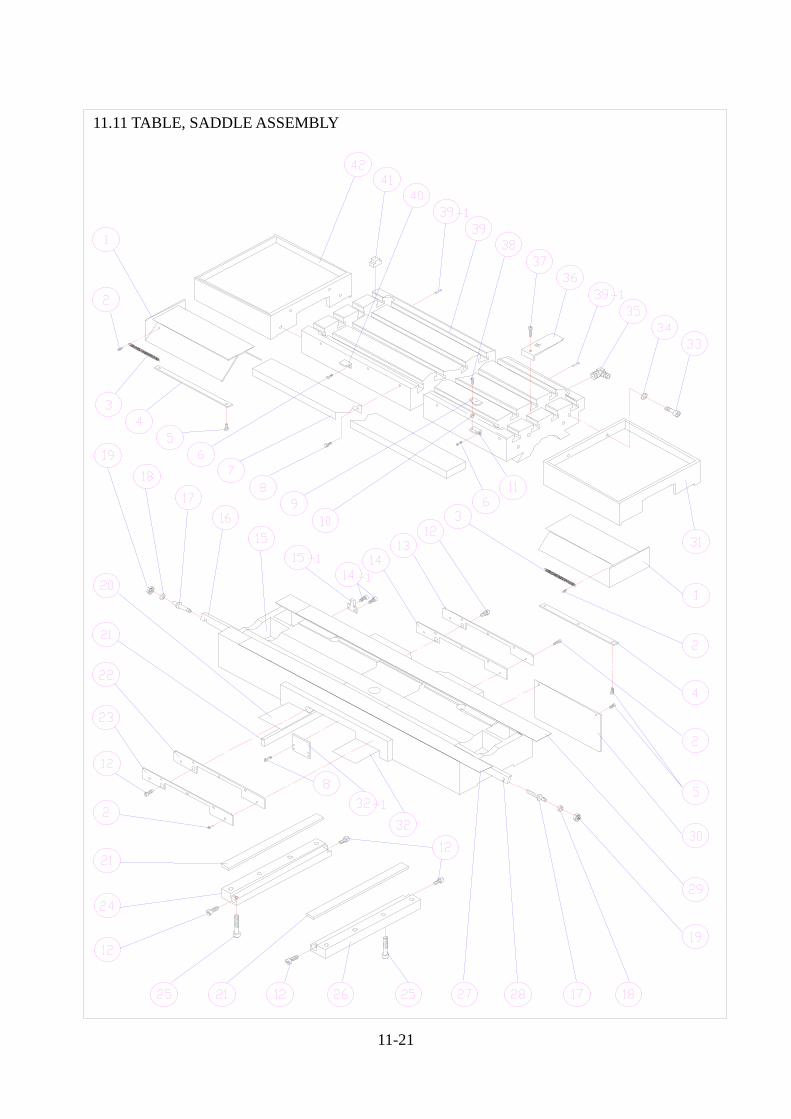
11.11 TABLE, SADDLE ASSEMBLY
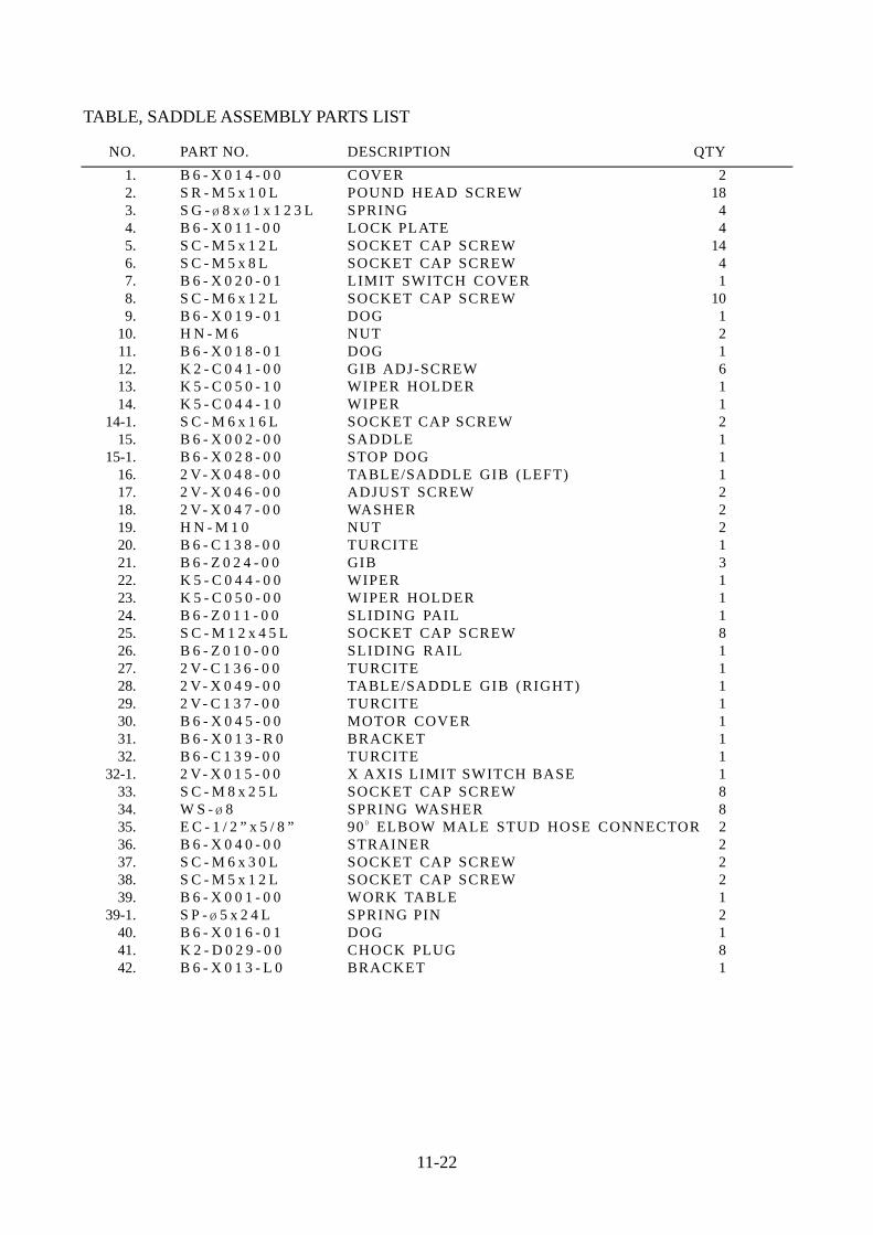
TABLE, SADDLE ASSEMBLY PARTS LIST
NO. PART NO. DESCRIPTION QTY 1. B 6 - X 0 1 4 - 0 0 COVER 2 2. S R - M 5 x 1 0 L POUND HEAD SCREW 18 3. S G - ¿ 8 x ¿ 1 x 1 2 3 L SPRING 4 4. B 6 - X 0 1 1 - 0 0 LOCK PLATE 4 5. S C - M 5 x 1 2 L SOCKET CAP SCREW 14 6. S C - M 5 x 8 L SOCKET CAP SCREW 4 7. B 6 - X 0 2 0 - 0 1 LIMIT SWITCH COVER 1 8. S C - M 6 x 1 2 L SOCKET CAP SCREW 10 9. B 6 - X 0 1 9 - 0 1 DOG 1 10. H N - M 6 NUT 2 11. B 6 - X 0 1 8 - 0 1 DOG 1 12. K 2 - C 0 4 1 - 0 0 GIB ADJ-SCREW 6 13. K 5 - C 0 5 0 - 1 0 WIPER HOLDER 1 14. K 5 - C 0 4 4 - 1 0 WIPER 1 14-1. S C - M 6 x 1 6 L SOCKET CAP SCREW 2 15. B 6 - X 0 0 2 - 0 0 SADDLE 1 15-1. B 6 - X 0 2 8 - 0 0 STOP DOG 1 16. 2 V- X 0 4 8 - 0 0 TABLE/SADDLE GIB (LEFT) 1 17. 2 V- X 0 4 6 - 0 0 ADJUST SCREW 2 18. 2 V- X 0 4 7 - 0 0 WASHER 2 19. H N - M 1 0 NUT 2 20. B 6 - C 1 3 8 - 0 0 TURCITE 1 21. B 6 - Z 0 2 4 - 0 0 GIB 3 22. K 5 - C 0 4 4 - 0 0 WIPER 1 23. K 5 - C 0 5 0 - 0 0 WIPER HOLDER 1 24. B 6 - Z 0 1 1 - 0 0 SLIDING PAIL 1 25. S C - M 1 2 x 4 5 L SOCKET CAP SCREW 8 26. B 6 - Z 0 1 0 - 0 0 SLIDING RAIL 1 27. 2 V- C 1 3 6 - 0 0 TURCITE 1 28. 2 V- X 0 4 9 - 0 0 TABLE/SADDLE GIB (RIGHT) 1 29. 2 V- C 1 3 7 - 0 0 TURCITE 1 30. B 6 - X 0 4 5 - 0 0 MOTOR COVER 1 31. B 6 - X 0 1 3 - R 0 BRACKET 1 32. B 6 - C 1 3 9 - 0 0 TURCITE 1 32-1. 2 V- X 0 1 5 - 0 0 X AXIS LIMIT SWITCH BASE 1 33. S C - M 8 x 2 5 L SOCKET CAP SCREW 8 34. W S - ¿ 8 SPRING WASHER 8 35. E C - 1 / 2 ” x 5 / 8 ” 90 ¼ ELBOW MALE STUD HOSE CONNECTOR 2 36. B 6 - X 0 4 0 - 0 0 STRAINER 2 37. S C - M 6 x 3 0 L SOCKET CAP SCREW 2 38. S C - M 5 x 1 2 L SOCKET CAP SCREW 2 39. B 6 - X 0 0 1 - 0 0 WORK TABLE 1 39-1. S P - ¿ 5 x 2 4 L SPRING PIN 2 40. B 6 - X 0 1 6 - 0 1 DOG 1 41. K 2 - D 0 2 9 - 0 0 CHOCK PLUG 8 42. B 6 - X 0 1 3 - L 0 BRACKET 1
11-22

11-23
11.12 TABLE, SADDLE (AXIS WITH HANDLE WHEEL) ASSEMBLY
TABLE, SADDLE (AXIS WITH HANDLE WHEEL) ASSEMBLY PARTS LIST
NO. PART NO. DESCRIPTION QTY 1. B 6 - X 0 1 4 - 0 0 COVER 2 2. S R - M 5 x 1 0 L POUND HEAD SCREW 18 3. S G - ¿ 8 x ¿ 1 x 1 2 3 L SPRING 4 4. B 6 - X 0 1 1 - 0 0 LOCK PLATE 4 5. S C - M 5 x 1 2 L SOCKET CAP SCREW 14 6. S C - M 5 x 8 L SOCKET CAP SCREW 4 7. B 6 - X 0 2 0 - 0 1 LIMIT SWITCH COVER 1 8. S C - M 6 x 1 2 L SOCKET CAP SCREW 6 9. B 6 - X 0 1 9 - 0 1 DOG 1 10. H N - M 6 NUT 2 11. B 6 - X 0 1 6 - A 1 DOG 1 12. K 2 - C 0 4 1 - 0 0 GIB ADJ-SCREW 6 13. K 5 - C 0 5 0 - 1 0 WIPER HOLDER 1 14. K 5 - C 0 4 4 - 1 0 WIPER 1 15. B 6 - X 0 0 2 - 0 0 SADDLE 1 16. 2 V- X 0 4 8 - 0 0 TABLE/SADDLE GIB (LEFT) 1 17. 2 V- X 0 4 6 - 0 0 ADJUST SCREW 2 18. 2 V- X 0 4 7 - 0 0 WASHER 2 19. H N - M 1 0 NUT 2 20. B 6 - C 1 3 8 - 0 0 TURCITE 1 21. B 6 - Z 0 2 4 - 0 0 GIB 3 22. K 5 - C 0 4 4 - 0 0 WIPER 1 23. K 5 - C 0 5 0 - 0 0 WIPER HOLDER 1 24. B 6 - Z 0 1 1 - 0 0 SLIDING PAIL 1 25. S C - M 1 2 x 4 5 L SOCKET CAP SCREW 8 26. B 6 - Z 0 1 0 - 0 0 SLIDING RAIL 1 27. 2 V- C 1 3 6 - 0 0 TURCITE 1 28. 2 V- X 0 4 9 - 0 0 TABLE/SADDLE GIB (RIGHT) 1 29. 2 V- C 1 3 7 - 0 0 TURCITE 1 30. B 6 - X 0 4 5 - 0 0 MOTOR COVER 1 31. B 6 - X 0 1 3 - R 0 BRACKET 1 32. B 6 - C 1 3 9 - 0 0 TURCITE 1 33. S C - M 8 x 2 5 L SOCKET CAP SCREW 8 34. W S - ¿ 8 SPRING WASHER 8 35. E C - 1 / 2 ” x 5 / 8 ” 90 ¼ ELBOW MALE STUD HOSE CONNECTOR 2 36. B 6 - X 0 4 0 - 0 0 STRAINER 2 37. S C - M 6 x 3 0 L SOCKET CAP SCREW 2 38. S C - M 5 x 1 2 L SOCKET CAP SCREW 2 39. B 6 - X 0 0 1 - 0 0 WORK TABLE 1 40. B 6 - X 0 1 6 - 0 1 DOG 1 41. K 2 - D 0 2 9 - 0 0 CHOCK PLUG 8 42. B 6 - X 0 1 3 - L 0 BRACKET 1 43. B 6 - X 0 4 3 - 0 0 HANDLE 1 44. H N - 5 / 8 ” - 1 8 U N F NUT 1 45. W S - ¿ 5 / 8 ” SPRING WASHER 1 46. B 6 - X 0 4 2 - 0 0 HANDLE WHEEL 1 47. B 6 - X 0 4 1 - 0 0 BUSHING 1 48. 6 0 0 4 Z BALL BEARING 2 49. D F - 3 0 5 3 - 0 0 HANDLE 1 50. B 6 - X 0 5 3 - 0 0 BRACET 1 51. K Y- 3 x 3 x 2 5 L KEY 1 52. B 6 - X 0 5 1 - 0 0 12T GEAR SHAFT 1
11-24

11-25
11.13 X, Y AXIS ASSEMBLY
X,Y AXIS ASSEMBLY PARTS LIST
NO PART NO DESCRIPTION QTY 1. S C - M 6 x 1 6 L SOCKET CAP SCREW 11 2. B 6 - X 0 1 2 - 0 0 BEARING CAP 1 3. S E - 2 0 SNAP RING 2 4. 6 2 0 4 Z Z BALL BEARING 1 5. T P - # 4 x 3 8 L TAPE PIN 12 6. 2 V- X 0 1 1 - 0 3 X AXIS BEARING BRACKET 1 7. T P - # 4 x 4 5 L TAPER PIN 1 8. S C - M 6 x 2 0 L SOCKET CAP SCREW 10 9. W S - ¿ 6 SPRING WASHER 8 10. K Y- 6 x 6 x 2 5 L KEY 2 11. B 6 - Y 0 8 0 - 0 0 Y AXIS FEED NUT BRACKET 1 12. 6 0 0 4 Z Z BALL BEARING 1 13. B 6 - YA 3 5 - 0 0 BEARING BRACKET 1 14. S C - M 8 x 2 0 L SOCKET CAP SCREW 2 15. 6 1 5 - 5 M x 2 7 HTD BELT 1 16. H N - 5 / 8 ” - 1 8 U N F NUT 4 17. B 6 - YA 0 8 - B 0 SPACER 1 18. B 6 - YA 0 7 - 0 0 Y AXIS BEARING BRACKET 1 19. 2 5 TA C 6 2 B BALL BEARING 4 20. B 6 - Y 0 3 0 - T 0 38T HTD GEAR 1 21. B 6 - YA 5 0 - M 0 Y AXIS BALL SCREW 1 22. S C - M 1 0 x 4 0 L SOCKET CAP SCREW 12 23. W S - ¿ 1 0 SPRING WASHER 24 24. M T S 3 0 U 4 - 3 6 SERVO MOTOR 2 25. K 5 - C 0 1 8 - 0 0 WASHER 1 26. S C - M 6 x 4 0 L SOCKET CAP SCREW 4 27. S C - M 1 0 x 2 5 L SOCKET CAP SCREW 4 28. S C - M 8 x 3 0 L SOCKET CAP SCREW 20 29. W S - ¿ 8 SPRING WASHER 20 30. B 6 - YA 1 1 - 0 0 BEARING CAP 2 31. S C - M 6 x 3 0 L SOCKET CAP SCREW 4 32. K Y- 3 / 1 6 ” x 2 5 L KEY 2 33. B 6 - Y 0 0 4 - 0 0 COVER 1 34. B 6 - Y 0 2 1 - 0 0 Y AXIS MOTOR BASE 1 35. B 6 - Y 0 1 5 - 0 0 MOTOR BRACKET 1 36. B 3 - X 0 3 1 - A 1 LOCK BLOCK 2 37. B 6 - X 0 0 8 - T 1 38T HTD PULLEY 2 38. 5 7 5 - 5 M x 2 7 HTD BELT 1 39. B 6 - X 0 2 5 - 0 0 X AXIS MOTOR BASE 1 40. S C - M 1 0 x 3 5 L SOCKET CAP SCREW 8 41. S R - M 5 x 8 L ROUND HEAD SCREW 4 42. B 6 - X 0 0 7 - 0 0 COVER 1 43. B 6 - X 0 0 4 - 0 0 X AXIS GEAR BOX 1 44. B 6 - X 0 0 5 - 0 0 X AXIS BEARING BRACKET 1 45. B 6 - X 0 1 7 - M 1 X AXIS BALL SCREW 1 46. B 6 - X 0 3 1 - 0 2 LOCK BLOCK 1 47. B 6 - X 0 3 0 - T 1 38T HTD GEAR 1 48. 2 V- X 0 0 3 - A 0 FEED NUT BRACKET 1
11-26
11-27
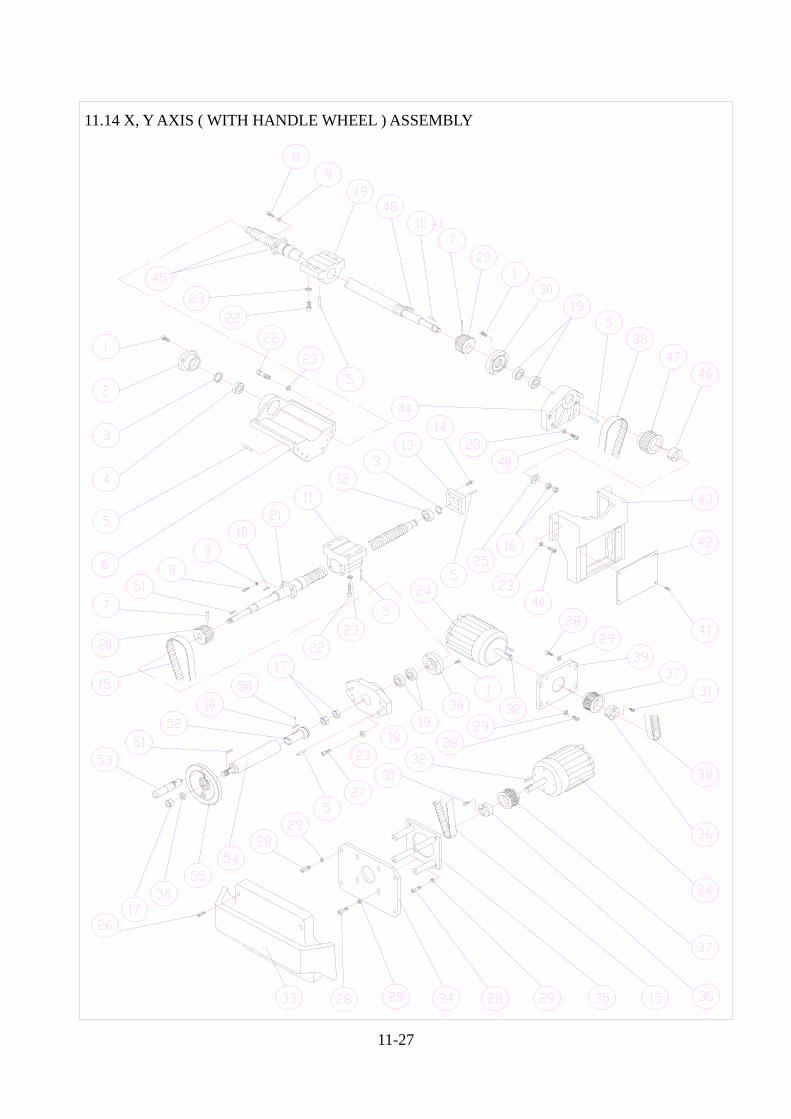
11.14 X, Y AXIS ( WITH HANDLE WHEEL ) ASSEMBLY
X,Y AXES (WITH HANDLE WHEEL) ASSEMBLY PARTS LIST
NO PART NO DESCRIPTION QTY 1. S C - M 6 x 1 6 L SOCKET CAP SCREW 11 2. B 6 - X 0 1 2 - 0 0 BEARING CAP 1 3. S E - 2 0 SNAP RING 2 4. 6 2 0 4 Z Z BALL BEARING 1 5. T P - # 4 x 3 8 L TAPE PIN 12 6. 2 V- X 0 1 1 - 0 3 X AXIS BEARING BRACKET 1 7. T P - # 4 x 4 5 L TAPER PIN 1 8. S C - M 6 x 2 0 L SOCKET CAP SCREW 10 9. W S - ¿ 6 SPRING WASHER 8 10. K Y- 6 x 6 x 2 5 L KEY 2 11. B 6 - Y 0 8 0 - 0 0 Y AXIS FEED NUT BRACKET 1 12. 6 0 0 4 Z Z BALL BEARING 1 13. B 6 - YA 3 5 - 0 0 BEARING BRACKET 1 14. S C - M 8 x 2 0 L SOCKET CAP SCREW 2 15. 6 1 5 - 5 M x 2 7 HTD BELT 1 16. H N - 5 / 8 ” - 1 8 U N F NUT 2 17. H N - ¿ 1 / 2 - 2 0 U N F NUT 3 18. B 6 - YA 0 7 - 0 0 Y AXIS BEARING BRACKET 1 19. 2 5 TA C 6 2 B BALL BEARING 4 20. B 6 - Y 0 3 0 - T 0 38T HTD GEAR 1 21. B 6 - YA 5 0 - M 0 Y AXIS BALL SCREW 1 22. S C - M 1 0 x 4 0 L SOCKET CAP SCREW 12 23. W S - ¿ 1 0 SPRING WASHER 24 24. M T S 3 0 U 4 - 3 6 SERVO MOTOR 2 25. K 5 - C 0 1 8 - 0 0 WASHER 1 26. S C - M 6 x 4 0 L SOCKET CAP SCREW 4 27. S C - M 1 0 x 2 5 L SOCKET CAP SCREW 4 28. S C - M 8 x 3 0 L SOCKET CAP SCREW 20 29. W S - ¿ 8 SPRING WASHER 20 30. B 6 - YA 1 1 - 0 0 BEARING CAP 2 31. S C - M 6 x 3 0 L SOCKET CAP SCREW 4 32. K Y- 3 / 1 6 ” x 2 5 L KEY 2 33. B 6 - Y 0 0 4 - 0 0 COVER 1 34. B 6 - Y 0 2 1 - 0 0 Y AXIS MOTOR BASE 1 35. B 6 - Y 0 1 5 - 0 0 MOTOR BRACKET 1 36. B 3 - X 0 3 1 - A 1 LOCK BLOCK 2 37. B 6 - X 0 0 8 - T 1 38T HTD PULLEY 2 38. 5 7 5 - 5 M x 2 7 HTD BELT 1 39. B 6 - X 0 2 5 - 0 0 X AXIS MOTOR BASE 1 40. S C - M 1 0 x 3 5 L SOCKET CAP SCREW 8 41. S R - M 5 x 8 L ROUND HEAD SCREW 4 42. B 6 - X 0 0 7 - 0 0 COVER 1 43. B 6 - X 0 0 4 - 0 0 X AXIS GEAR BOX 1 44. B 6 - X 0 0 5 - 0 0 X AXIS BEARING BRACKET 1 45. B 6 - X 0 1 7 - M 1 X AXIS BALL SCREW 1 46. B 6 - X 0 3 1 - 0 2 LOCK BLOCK 1 47. B 6 - X 0 3 0 - T 1 38T HTD GEAR 1 48. K Y- 6 x 6 x 3 5 L KEY 1 49. 2 V- X 0 0 3 - A 0 FEED NUT BRACKET 1 50. S P - ¿ 3 x 8 SPRING PIN 1 51. K Y- 3 x 3 x 2 5 L KEY 3 52. B 6 - YA 0 8 - A 0 SPACER 1 53. B 6 - X 0 4 3 - 0 0 HANDLE 1 54. B 6 - YA 1 5 - 0 0 HANDLE WHEEL CONNECT SHAFT 1 55. B 6 - X 0 4 2 - 0 0 HANDLE WHEEL 1 56. W S - ¿ 5 / 8 ” SPRING WASHER 1
11-28
11-29
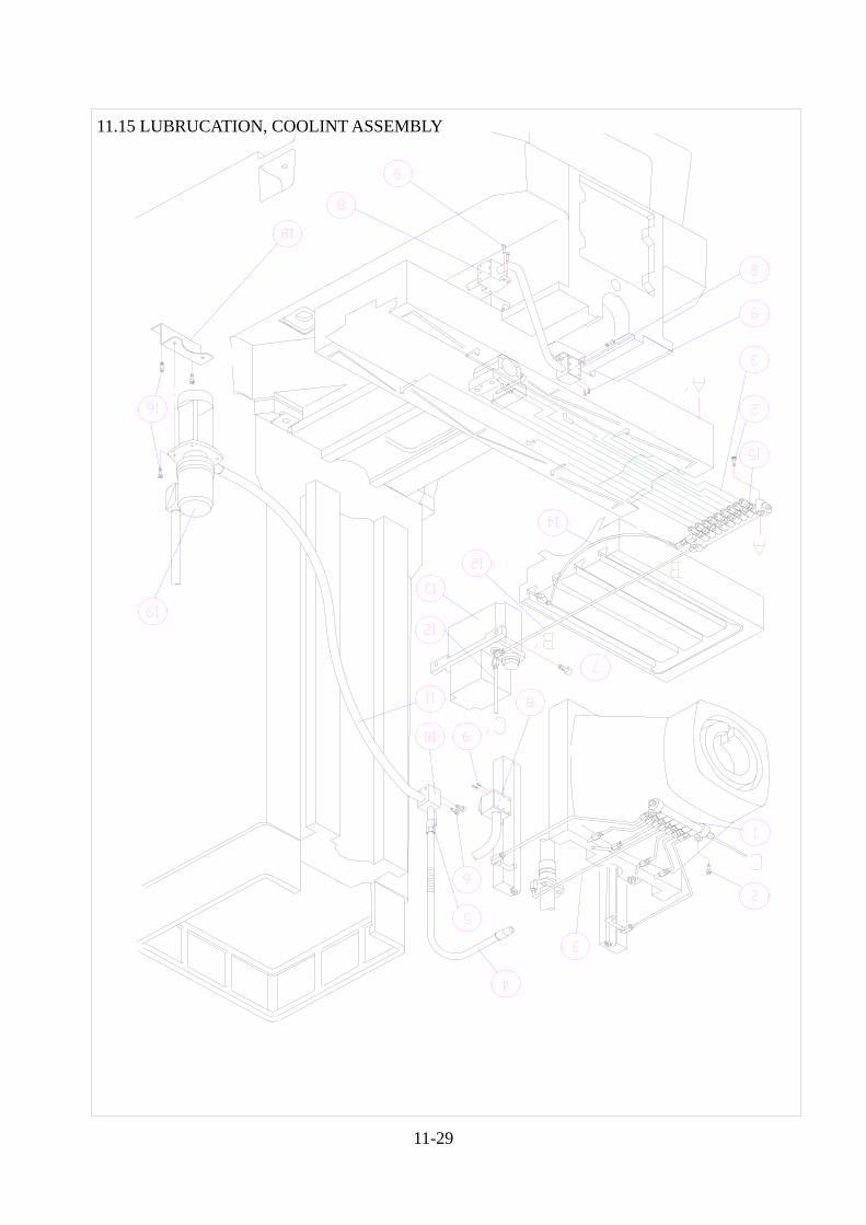
11.15 LUBRUCATION, COOLINT ASSEMBLY
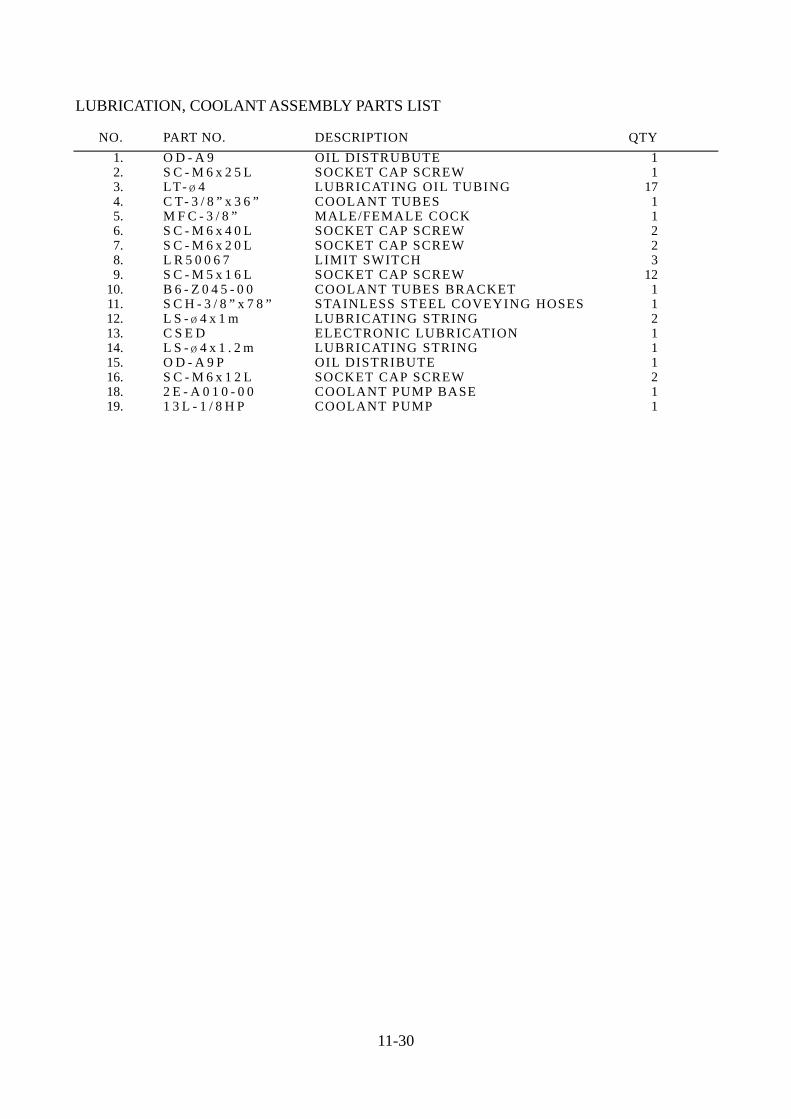
LUBRICATION, COOLANT ASSEMBLY PARTS LIST
NO. PART NO. DESCRIPTION QTY 1. O D - A 9 OIL DISTRUBUTE 1 2. S C - M 6 x 2 5 L SOCKET CAP SCREW 1 3. LT- ¿ 4 LUBRICATING OIL TUBING 17 4. C T- 3 / 8 ” x 3 6 ” COOLANT TUBES 1 5. M F C - 3 / 8 ” MALE/FEMALE COCK 1 6. S C - M 6 x 4 0 L SOCKET CAP SCREW 2 7. S C - M 6 x 2 0 L SOCKET CAP SCREW 2 8. L R 5 0 0 6 7 LIMIT SWITCH 3 9. S C - M 5 x 1 6 L SOCKET CAP SCREW 12 10. B 6 - Z 0 4 5 - 0 0 COOLANT TUBES BRACKET 1 11. S C H - 3 / 8 ” x 7 8 ” STAINLESS STEEL COVEYING HOSES 1 12. L S - ¿ 4 x 1 m LUBRICATING STRING 2 13. C S E D ELECTRONIC LUBRICATION 1 14. L S - ¿ 4 x 1 . 2 m LUBRICATING STRING 1 15. O D - A 9 P OIL DISTRIBUTE 1 16. S C - M 6 x 1 2 L SOCKET CAP SCREW 2 18. 2 E - A 0 1 0 - 0 0 COOLANT PUMP BASE 1 19. 1 3 L - 1 / 8 H P COOLANT PUMP 1
11-30