Embed Size (px)
Citation preview

TECHNICAL SPECIFICATIONS:
SUPPLY, INSTALLATION & COMMISSIONING OF AUTOMATIC ACTUATED RIM SEAL FIRE DETECTION & FOAM BASED FIRE EXTINGUISHING SYSTEM AS PER OISD-117 FOR EXTERNAL FLOATING ROOF STORAGE TANKS (EFRT) OF BPCL’S POL LOCATIONS STORING CLASS-A PETROLEUM PRODUCTS
TECHNICAL SPECIFICATIONS FOR SUPPLY, INSTALLATION & COMMISSIONING OF AUTOMATIC ACTUATED RIM SEAL FIRE
DETECTION & FOAM BASED FIRE EXTINGUISHING SYSTEM AS PER OISD-117 FOR EXTERNAL FLOATING ROOF STORAGE
TANKS (EFRT) OF BPCL’S POL LOCATIONS STORING CLASS-A PETROLEUM PRODUCTS
Page 1 of 52

1.0 SCOPE :
This specification covers design, engineering, fabrication, calibration, testing supply, installation and commissioning of automatic actuated Rim seal fire detection and foam based extinguishing system for external floating roof tanks (EFRT) storing class “A” petroleum products in line with OISD standard 117. Only those Rim seal protection systems, which use the linear heat hollow metallic tube type detectors with foam based extinguishing media shall be used. These detection systems shall be certified by any of the international certifying agencies like UL, FM, Vds or LPC to ensure that those systems are used which meet with the highest international standard of safety certification. The automatic actuated Rim seal fire Detection & Extinguishing system shall consist of:
a. Linear Heat Hollow metallic tube type detection system. b. Automatic Foam based Fire Extinguishing system c. Control and monitoring of heat detection and Fire extinguishing system. d. Associated Cabling & Piping
2.0 OBJECTIVE OF THE AUTOMATIC RIM SEAL FIRE DETECTION AND EXTINGUISHING SYSTEM :
The overall purpose of the system is to detect and extinguish the Rim seal fire over external floating roof tanks storing class “A” Petroleum products at the incipient stage and simultaneously alert the personnel at the facility so that they can respond to the incident.
3.0 APPLICABLE CODES AND STANDARDS:
a. OISD standard 117 (latest edition) b. NFPA 11 2010: Standard for low expansion Foam c. Factories Rules – for applicable States. d. Indian Electricity Rules & Relevant Bureau of Indian standards e. ASME Section VIII Div. I & ASME 31.3 f. Cylinder rules and Static and Mobile Pressure Vessels (unfired) rules g. Petroleum Explosives and Safety Organizations (PESO) Rules h. Relevant UL/FM/VdS/LPC & EN Standards i. API-650 j. Any other applicable codes and standards
Note: Where edition number of standards referred are not indicated, latest editions shall apply.
TECHNICAL SPECIFICATIONS FOR SUPPLY, INSTALLATION & COMMISSIONING OF AUTOMATIC ACTUATED RIM SEAL FIRE
DETECTION & FOAM BASED FIRE EXTINGUISHING SYSTEM AS PER OISD-117 FOR EXTERNAL FLOATING ROOF STORAGE
TANKS (EFRT) OF BPCL’S POL LOCATIONS STORING CLASS-A PETROLEUM PRODUCTS
Page 2 of 52

4.0 BASIC DESCRIPTION OF THE SYSTEM
The system consists of a microprocessor based; site configurable Hollow Metallic Tube type Linear Heat Detection system monitoring the rim seal area over the whole tank circumference. The hollow metallic steel detection tubing, which is laid around the whole circumference in the rim seal area of the floating roof tank, along with the Detector box, rapidly detects the fire on the rim seal at its incipient stage (within 10 seconds of its occurrence) due to an increase in pressure inside the tube as a result of heat generated due to fire. On detection, system shall be capable of raising an alarm at manned location/s and shall automatically discharge low expansion foam solution (stored on the tank roof) over the rim seal area of the tank. The Fire detection & Fire extinguishing system shall be mounted on the pontoon of the floating roof tank & shall be modular type with each module protecting a defined length of rimseal area. All the foam extinguishing modules shall be designed to discharge foam solution simultaneously on the entire rim seal area, on detection of fire at any location of the rim seal by any of the fire detection modules. The detection system shall have programmable self diagnostic facility with annunciation of status displayed on the panels placed in the Control Room / Security cabin. The minimum requirement for the design of the system is given below:
5.0 Linear Heat Detection(LHD) system :
5.1 Principle of Operation:
Linear Heat Detection Systems work on the principle of change in pressure of gases (air) caused by rise in temperature in a close circuit metallic sensor tube. The system shall be able to sense the rapid rate of rise as well as preset maximum temperature to ensure that any incipient fire on rim seal is detected within 10 seconds of occurrence. The Pneumatically tight system is formed by the sensor tube, which is sealed at its one end and connected at the other end to a detector box, which contains an electronic pressure sensor, a suitable device / mechanism for self diagnostic / real time monitoring of effectiveness of the detection system. The principle of the detection, alarm and actuation shall be as under : Detection The Detection system shall be programmed to detect :
a. Rate of rise in temperature
TECHNICAL SPECIFICATIONS FOR SUPPLY, INSTALLATION & COMMISSIONING OF AUTOMATIC ACTUATED RIM SEAL FIRE
DETECTION & FOAM BASED FIRE EXTINGUISHING SYSTEM AS PER OISD-117 FOR EXTERNAL FLOATING ROOF STORAGE
TANKS (EFRT) OF BPCL’S POL LOCATIONS STORING CLASS-A PETROLEUM PRODUCTS
Page 3 of 52

as well as
b. Absolute maximum temperature
Alarms There shall be 2 site configurable alarms for both the above situations. a. Rate of rise : Alarm should be generated at a preset rate of rise of
temperature
as well as b. Maximum temperature : Alarm should also be generated at a preset
temperature
Actuation The actuation of the foam suppression system ( which shall be site configurable) shall occur in all the following cases :
a. Rate of Rise: Rate of rise of temperature has reached a preset value, which will be higher than that for Alarm.
b. Maximum Temperature: The temperature has reached a preset value,
which will be higher than that for alarm.
c. When both ‘a’ AND ‘b’ occur
5.2 LHD Mounting
The LHD sensor tube should be provided between primary and secondary seal for early detection of incipient fire. LHD tube mounts shall be such that it can accommodate tank flexing & movement without causing chaffing or other damage to the tube. Bidders shall supply all necessary fixing brackets, sleeves, clamps or other devices required to install the sensor tube on the floating roof tank.
5.3 Detection system requirements: • The sensor (metallic tube) element shall be reusable after exposure to
incipient fire and rapid extinguishment. The detection system shall be resettable after actuation. The detection system shall be restored for service
TECHNICAL SPECIFICATIONS FOR SUPPLY, INSTALLATION & COMMISSIONING OF AUTOMATIC ACTUATED RIM SEAL FIRE
DETECTION & FOAM BASED FIRE EXTINGUISHING SYSTEM AS PER OISD-117 FOR EXTERNAL FLOATING ROOF STORAGE
TANKS (EFRT) OF BPCL’S POL LOCATIONS STORING CLASS-A PETROLEUM PRODUCTS
Page 4 of 52

after event occurrence from the Control Room without the need for access to the protected area.
• The Sensor tube shall be hollow metallic S.S. tube of suitable diameter and
thickness in line with international certification agencies like UL / VdS/ FM/ LPC, free from glass, fiber, and rubber & plastic for its long and dependable service.
• The LHD evaluation unit shall either be flame proof / intrinsically safe or
shall be housed in a flameproof enclosure and installed alongside one of the extinguishing systems (Foam Module) installed on the tank roof / pontoon.
• The linear heat detection system shall have a suitable device / mechanism
for self diagnostic / real time monitoring of effectiveness of the detection system.
• When the entire length of linear heat metallic detection tube as per
approved design is kept at a height of 300 mm above the centre line along the length of 300 mm wide and 6.0 M meter long fire tray containing motor spirit & fuel is set on fire, the fire alarm & actuation of foam suppression system should not start later than 10 seconds from the inception of fire.
• The linear heat detection system shall provide fire alarm/fault signals
separately for each tank at the rim seal main fire alarm panel at Control Room / LCP /security cabin.
• The Graphic Console provided in the control room shall have the capability
of storing system specific parameters and event logging for all the tanks covered under rim seal protection system.
• The Detection system shall be site configurable for rate of rise and /or
maximum temperature at two different alarm thresholds at Graphic console & rim seal main fire alarm panel.
• The Detection system shall be of decentralised type i.e. individual detection
system (sensor tube with evaluation unit) for individual tank shall be independent & shall be mounted on the tank roof itself.
• The system shall have the facility for interface to the Laptop for site
configuration at rim seal main fire alarm panel and LCP and setting the parameters of the system. Suitable port connectivity with Desktop Workstation at Control Room shall be provided for diagnosis and graphic HMI.
TECHNICAL SPECIFICATIONS FOR SUPPLY, INSTALLATION & COMMISSIONING OF AUTOMATIC ACTUATED RIM SEAL FIRE
DETECTION & FOAM BASED FIRE EXTINGUISHING SYSTEM AS PER OISD-117 FOR EXTERNAL FLOATING ROOF STORAGE
TANKS (EFRT) OF BPCL’S POL LOCATIONS STORING CLASS-A PETROLEUM PRODUCTS
Page 5 of 52

• All field junction boxes/instruments/electrical equipment shall be provided
with prefabricated canopy ( pre-coated sheets) • Software for the detection system shall be capable to configure site specific
graphics with authorisation for use of the software for a minimum of 5 years at a particular facility. The documented authorisation shall accompany the software at the time of supply. Software shall have provision to configure at least 2 additional tanks in future.
The system shall have fail safe / diagnostic features as per the criteria given in Annexure-1.
5.4 Installation requirements:
The LHD & automatic foam suppression system is required to be installed on the tank roof as per approved drawings & after obtaining confirmation of the tank roof being capable of holding the subject system. No modification or alterations will be allowed on the main tank shell or on the floating roof. Rim seal fire protection system design shall be suitable in accordance with the individual tank design.
It is recognized that erection of rim seal fire protection system on floating roof tank shall be carried out while the tank shall be out of service in gas free condition. The floating roof shall be made to float on water during execution of job. Also, vendor to note that there may be other agencies working on the roof simultaneously on other activities, viz providing addl. Nozzles for high level switch etc. The following condition shall be complied with during installation of rim seal protection system on the tanks:
a. Bidder shall comply fully with all safe working practices and Permit to Work
system of the owner. b. No hot work shall be allowed on the tank. c. All persons working on the roof shall use required personal protective
equipment & retractable type fall arrestor system. d. The SS sensor tube shall be securely laid using SS clips and screws with
provision for linear expansion. e. While working on tank roof, non-sparking tools only shall be used.
TECHNICAL SPECIFICATIONS FOR SUPPLY, INSTALLATION & COMMISSIONING OF AUTOMATIC ACTUATED RIM SEAL FIRE
DETECTION & FOAM BASED FIRE EXTINGUISHING SYSTEM AS PER OISD-117 FOR EXTERNAL FLOATING ROOF STORAGE
TANKS (EFRT) OF BPCL’S POL LOCATIONS STORING CLASS-A PETROLEUM PRODUCTS
Page 6 of 52

f. Bidder shall be required to submit detailed procedure for installation of rim seal protection system on the tanks. The same shall be required to be approved by owner / owner’s authorized representatives before commencement of the job
. 6.0 Automatic Foam based Fire extinguishing System:
6.1 Design :
A large storage tank may require one or more than one modular units for foam application on the entire rim seal area. Each such unit shall consist of a foam distribution piping, laid along the tank perimeter over the rim seal area. The spray nozzles for foam application are mounted on the distribution pipe at suitable intervals for full coverage of the rim seal area. Distribution pipe is permanently connected to a storage vessel containing pre-mix foam and both are placed on the roof. The foam solution contained in the storage vessel is kept always pressurized with nitrogen.
The automatic Rim seal foam suppression / fire extinguishing system shall consist of appropriate number of equally spaced identical modular foam units mounted adjacent to but outside the containment area of the foam dam so as to protect the entire rim seal area. The foam units shall be charged with pre-mixed foam solution pressurized with nitrogen as an expellant gas. All modules on a tank shall be actuated simultaneously in the event of automatic detection of fire from any detec€tor (in case of more than one linear heat detector) on the tank roof or by actuation of a manual release station outside the bund.
The system shall be designed for a minimum foam application rate of 18 lpm /m2 of rim seal surface area. An application period of minimum 40 seconds shall be considered.
The system shall be modular in design with each section of foam distribution manifold protecting an equal length of Rimseal area. In order to ensure full foam coverage in the entire rimseal area, the placement of the nozzle shall be such that foam application shall be uniform including the area at the ends of the manifold. The nozzle shall be made of SS-316/chrome plated brass.
6.2 Foam solution modules:
a. Stainless Steel (SS-316) Foam solution storage tank for each foam module shall
be designed to meet foam application rate of minimum 18 lpm/m2 of protected rim seal area for an application period of minimum 40 seconds. However, the maximum capacity of each foam solution storage tank shall not exceed 250 litres. The specification of Stainless steel and fabrication of Foam solution tanks shall be
TECHNICAL SPECIFICATIONS FOR SUPPLY, INSTALLATION & COMMISSIONING OF AUTOMATIC ACTUATED RIM SEAL FIRE
DETECTION & FOAM BASED FIRE EXTINGUISHING SYSTEM AS PER OISD-117 FOR EXTERNAL FLOATING ROOF STORAGE
TANKS (EFRT) OF BPCL’S POL LOCATIONS STORING CLASS-A PETROLEUM PRODUCTS
Page 7 of 52

as per attached specifications. b. Foam solution storage tank shall be manufactured to ASME-VIII, Div-1
requirements .Indicative drawings have been attached to this specification. c. Foam Discharge Manifold and distribution pipe work with semi aspirating foam
spray nozzles (expansion ratio 1:3 to 1:6) shall be UL listed /Vds/ FM/ LPC approved & made of SS-316 / Chrome Plated Brass and evenly spaced to cover one segment of rim seal up-to maximum length of 50 meters. This shall be designed for delivering foam at 18 lpm/m2 and extinguishing of fire within 40 seconds of detection.
d. Automatic Foam Discharge actuation valve shall be provided at discharge outlet. e. Instrumentation Panel containing nitrogen charging port, Distribution Manifold,
pressure switch to monitor foam module pressure, etc. shall be installed on each foam module.
f. Pre-coated canopy shall be provided on each foam module for protection from
direct impingement by sunlight & rain water. g. Clearly legible schematic and operating instruction plate shall be permanently
fixed on each foam module. h. Suitable sized filling and draining facilities shall be provided for operation and
maintenance of modules. i. Each foam module shall be fitted with a pressure gauge/pressure switch of suitable
range to manually identify module pressure. Additionally, the signal from the pressure switch shall terminated into the Local junction box and a common signal for “Module pressure low” shall be transmitted for each tank to the LCP, Rim seal fire alarm panel at the control room.
j. One Test discharge connection with nozzle shall be provided to allow testing of
system without discharging foam into Rim seal area.
6.3 Foam system general requirements :
a. The foam discharge nozzles of extinguishing system shall be positioned above
primary seal & below secondary seal/weather shield after puncturing weather shield/secondary seal.
b. The Extinguishing / Suppression system shall be capable of actuation by LHD
TECHNICAL SPECIFICATIONS FOR SUPPLY, INSTALLATION & COMMISSIONING OF AUTOMATIC ACTUATED RIM SEAL FIRE
DETECTION & FOAM BASED FIRE EXTINGUISHING SYSTEM AS PER OISD-117 FOR EXTERNAL FLOATING ROOF STORAGE
TANKS (EFRT) OF BPCL’S POL LOCATIONS STORING CLASS-A PETROLEUM PRODUCTS
Page 8 of 52

system locally without requirement of any signal from the Fire Alarm Panels outside the tank dyke.
c. All the piping coming in contact with foam solution shall be of SS 316. d. Pipe supports shall be designed and located to effectively sustain the weight
and thermal effects of piping system and to prevent its vibration. e. The piping shall be provided with the required number of valves, bends, and
fittings for the efficient functioning of the system. f. Module Pressure Low signals shall be available from the unit.
6.4 AQUEOUS FILM FORMING FOAM-AFFF
Selection and design of foam based rim seal fire protection system shall be as defined in the latest NFPA – 11 & 11A Standard for Low and Medium Expansion Foam. Film Forming Fluro Protein Foam (FFFP) / Aqueous Film Forming Foam (AFFF) type Concentrate is to be used in the system as specified in these specifications
Foam concentrate to be used in the rimseal fire protection system shall be UL listed / BIS approved 3% concentrate Aqueous film forming foam (AFFF) or 3% type Film Forming Flouro Protein (FFFP) or 3%/3% Alcohol Resistant-Aqueous Film Forming Foam (AR-AFFF).
The specifications shall be as per Annexure II.
7.0 Alarm & Auto Actuation System: The system shall be such that after any Rim-seal fire event it can be quickly reinstated by trained site personnel without the need for specialist engineers.
In case of fire on the rim seal, it is automatically detected by a device capable to sense the same. The device then actuates the spray system for application of foam in the complete area of rim seal to quickly extinguish the fire in its incipient stage. An audio-visual alarm is also coupled with the detection & extinguishing system for necessary fire alert.
The system includes a fire detector network which senses fire and actuates the automatic release of the extinguishing medium on the rim seal area. Each tank shall have Independent detection & extinguishing system.
TECHNICAL SPECIFICATIONS FOR SUPPLY, INSTALLATION & COMMISSIONING OF AUTOMATIC ACTUATED RIM SEAL FIRE
DETECTION & FOAM BASED FIRE EXTINGUISHING SYSTEM AS PER OISD-117 FOR EXTERNAL FLOATING ROOF STORAGE
TANKS (EFRT) OF BPCL’S POL LOCATIONS STORING CLASS-A PETROLEUM PRODUCTS
Page 9 of 52

The validity of the approach must be demonstrated by the designer for an effective total Flooding extinguishing system which quickly detects and extinguishes fire in its incipient stage without re-flash. Also, the design considerations should include the impact of the weight of the modules placed on the floating roof.
The detection system needs to be highly reliable and shall work at varied site ambient temperatures for protection of rim seal fire. Only those Rim seal protection systems, which use the linear heat hollow metallic tube type detectors with foam based extinguishing media shall be used. These detection systems shall be certified by any of the international certifying agencies like UL, FM, VdS or LPC to ensure that those systems are used which meet with highest international standards of safety certification.
8.0 Alarm & Control Panels:
Graphic console and rim seal main fire alarm panel shall be provided at manned locations (Control Rooms) and LCP (Local Control panel) is placed outside dyke for control and monitoring of the system. Repeater Panel for indications/alarm of FIRE and FAULT shall be provided at security cabin as applicable.
8.1 Local Control Panel (LCP):
There shall be one no. common Explosion proof Junction Box & Explosion proof local control panel (LCP) as minimum for every 2 tanks located in the same a tank dyke . Such Junction boxes & LCP’s shall be provided outside the Tank dyke area with system status annunciation lights and sounder (Fire, Fault, common Foam Module Pressure Low per tank) to alert the field personal of any alarm or fault condition of the Rimseal protection system. The panel shall be provided with a pre-coated canopy. There shall be no junction box within tank dyke area.
8.2 Emergency Actuation point ( Integral to LCP):
Manual Actuation point shall be provided on the Local control panel (LCP) to be located outside the tank dyke for manual action of foam extinguishing / suppression system on each tank. There shall be separate manual actuation point for each tank.
Manual Actuation Point (MAP) shall be painted & labeled with fluorescent paint clearly indicating the relevant tank numbers. It should require two operations for actuation.
8.3 Rim seal Main Fire Alarm Panel at control Room/Operator Cabin:
TECHNICAL SPECIFICATIONS FOR SUPPLY, INSTALLATION & COMMISSIONING OF AUTOMATIC ACTUATED RIM SEAL FIRE
DETECTION & FOAM BASED FIRE EXTINGUISHING SYSTEM AS PER OISD-117 FOR EXTERNAL FLOATING ROOF STORAGE
TANKS (EFRT) OF BPCL’S POL LOCATIONS STORING CLASS-A PETROLEUM PRODUCTS
Page 10 of 52
Site specific designed Rimseal main Fire Alarm Panel (FAP) shall be provided at the relevant Control Room/operator Cabin for r e m o t e indication of the signals from the detection and extinguishing/ suppression system. The panel shall be designed to accommodate all the tanks getting protected by rim seal protection system at the location under this tender with a provision for two additional future tanks. As a minimum, each panel shall be compatible for 4 tanks. Bidder to inform the maximum number of modules / tanks that can be configured with the offered graphic HMI software and the Rim seal main fire alarm Panel.
The panel shall be provide with a volt meter & ammeter to monitor incoming power supply from UPS
This panel should have visual and audible alarm with resetting facility. An annunciation window shall be provided on the front face of the panel. The following signals shall be available in the panel:
• Fire - flashing light and sounder • Detector Fault – flashing light and sounder • Cable Fault – flashing light and sounder • Module pressure low (common per tank) – flashing light and sounder • Total system is healthy –Constantly illuminated green light
Repeater Panel (Optional) for only indication of fire for all tanks under protection shall be provided at security cabin.
8.4 Graphic Console (HMI):
One Graphic Console of adequate capacity (LG/Samsung/Sony/Panasonic make 21 inch LCD) with software shall be provided in the control room to monitor Rim seal Fire protection system installed on all the tanks. Graphical representation of tanks should be configured in the console with unique site based layout of tank farm.
The console shall have features of tank number with Pop-up, event logging, history and prints. It shall be able to maintain historical data of alarm and faults for minimum 30 days.
The system hardware & software shall be designed to accommodate all the tanks getting protected by rim seal protection system at the location under this tender with a provision for two additional future tanks. As a minimum, the system shall be compatible for 4 tanks. Bidder to inform the maximum number of modules / tanks
TECHNICAL SPECIFICATIONS FOR SUPPLY, INSTALLATION & COMMISSIONING OF AUTOMATIC ACTUATED RIM SEAL FIRE
DETECTION & FOAM BASED FIRE EXTINGUISHING SYSTEM AS PER OISD-117 FOR EXTERNAL FLOATING ROOF STORAGE
TANKS (EFRT) OF BPCL’S POL LOCATIONS STORING CLASS-A PETROLEUM PRODUCTS
Page 11 of 52
that can be configured with the offered graphic HMI software and the Rim seal main fire alarm Panel.
The console shall have facility for simulating the fire protection system for checking the performance.
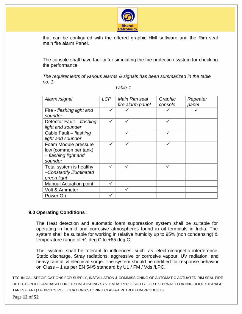
The requirements of various alarms & signals has been summarized in the table no. 1:
Table-1
Alarm /signal LCP Main Rim seal fire alarm panel
Graphic console
Repeater panel
Fire - flashing light and sounder
Detector Fault – flashing light and sounder
Cable Fault – flashing light and sounder
Foam Module pressure low (common per tank) – flashing light andsounder
Total system is healthy –Constantly illuminatedgreen light
Manual Actuation point Volt & Ammeter Power On
9.0 Operating Conditions :
The Heat detection and automatic foam suppression system shall be suitable for operating in humid and corrosive atmospheres found in oil terminals in India. The system shall be suitable for working in relative humidity up to 95% (non condensing) & temperature range of +1 deg C to +65 deg C.
The system shall be tolerant to influences such as electromagnetic interference, Static discharge, Stray radiations, aggressive or corrosive vapour, UV radiation, and heavy rainfall & electrical surge. The system should be certified for response behavior on Class – 1 as per EN 54/5 standard by UL / FM / Vds /LPC.
TECHNICAL SPECIFICATIONS FOR SUPPLY, INSTALLATION & COMMISSIONING OF AUTOMATIC ACTUATED RIM SEAL FIRE
DETECTION & FOAM BASED FIRE EXTINGUISHING SYSTEM AS PER OISD-117 FOR EXTERNAL FLOATING ROOF STORAGE
TANKS (EFRT) OF BPCL’S POL LOCATIONS STORING CLASS-A PETROLEUM PRODUCTS
Page 12 of 52

All enclosures for electrical equipment shall be suitable for use in Zone 1, Gas group IIA/IIB as per hazardous area classification & approved by PESO India. Bidder shall submit valid test certificates issued by PESO, India irrespective of country of origin. The test certificate for enclosure shall contain details of the components installed in it. As a minimum, all enclosures and instruments in the field shall be dust proof & weather proof to IP65.
10.0 FAIL SAFE / DIAGNOSTIC PHILOSOPHY :
The system should have features that ensure fail safe operation of the rim seal fire protection system on floating roof storage tanks even under abnormal conditions. To ensure the fail safe operation of the rim seal fire protection system, the system should be designed in such a way that in the event of any failures within the system due to any reasons like cable damage, power failure, mechanical damage due to excavation, movement of heavy machinery or adverse environmental conditions, the system should function as per details provided in Annexure- I.
11.0 Approvals, Authorization & Performance:
11.1 Following approvals are required to be made available along with the bid
a) Valid certifications from any of the international certifying agencies like
UL,FM,VDS or LPC for Linear heat detection system . Evaluation unit shall either be FLP/ intrinsically safe by itself or shall be housed in a FLP box having CMRI/PESO approvals mentioning details of components housed inside the FLP box including the sensor tube entering the FLP box.
b) 3 % type- AFFF/FFFP or 3 % / 3% type AR-AFFF foam conforming to UL listing/ BIS approvals to be used in the system.
c) Valid UL listing or Vds/FM /LPC approvals for foam spray nozzles.
All above approvals / certifications / listing, shall be valid as on due date of submission of Bids.
11.2 All the FLP enclosures shall be CMRI/ PESO approved for the intended hazardous area. Valid PESO approval for the same should be available with the bidder at the time of bid submission
11.3 Following authorizations shall be required along-with the bid;
a. If the bidder is not the manufacturer of Linear Heat detection system / Automatic foam based fire extinguishing system then following documents
TECHNICAL SPECIFICATIONS FOR SUPPLY, INSTALLATION & COMMISSIONING OF AUTOMATIC ACTUATED RIM SEAL FIRE
DETECTION & FOAM BASED FIRE EXTINGUISHING SYSTEM AS PER OISD-117 FOR EXTERNAL FLOATING ROOF STORAGE
TANKS (EFRT) OF BPCL’S POL LOCATIONS STORING CLASS-A PETROLEUM PRODUCTS
Page 13 of 52

are required to be submitted from the manufacturers of the Linear heat Detection and / or Automatic foam based Fire extinguishing system:
i. Undertaking from the OEM of Linear heat Detection and / or
Automatic foam based Fire extinguishing system that “all necessary technical , logistic & after sales support including all software & hardware (including spares) shall be provided for at least a period of 10 years from date of supply, including commissioning assistance mentioning clearly the specific tender no.”
b. If the bidder is a manufacturer of either or both the sub-systems (heat
detection & automatic foam suppression systems), Bidder shall be required to submit above undertakings along with the bid.
12.0 Electrical & Instrumentation System:
a. Power cables shall be stranded copper conductor of minimum 2.5mm2 FRLS cables or higher according to power requirements. All cables shall be XLPE as per IS 7098.
b. All signal & control cables shall be multi core 1.5 sq mm armoured copper FRLS
cables. All cables shall be PVC insulated. c. Cable to be laid over tank roof shall have length and mounting suitable for tank roof
movement over the entire height. Provision shall be made to prevent snagging of the cable. It shall take account of tank roof movement and wind conditions. Routing shall be done along the tank stair case / rolling ladder with necessary arrangement to ensure that the cable does not snag under the ladder wheels. Cables laid aboveground shall be in GI cable trays of suitable size. Bidder shall ensure that the bending radius of the cables (power / control / signal) has been considered during cable selection for the cables provided on tank top considering the movement of the tank roof deck.
d. All the cables within dyke area shall be laid above ground. e. Cable Joints shall not be used for signal and control cables. There shall not be any
cable joints for power cables inside the tank dyke. f. All cable glands shall be provided with PVC shrouds to prevent ingress of moisture
and rain water inside the enclosures.
TECHNICAL SPECIFICATIONS FOR SUPPLY, INSTALLATION & COMMISSIONING OF AUTOMATIC ACTUATED RIM SEAL FIRE
DETECTION & FOAM BASED FIRE EXTINGUISHING SYSTEM AS PER OISD-117 FOR EXTERNAL FLOATING ROOF STORAGE
TANKS (EFRT) OF BPCL’S POL LOCATIONS STORING CLASS-A PETROLEUM PRODUCTS
Page 14 of 52

g. All power cables having more than three cores shall have a minimum of 20% spare cores .
h. All multicore cables ( Power , signal & control cables ) shall have 20 % spare cores for future expannsion/ maintenance.
i. Power distribution network shall be designed in such a way that single point failureshall not cause tripping of the total system. Each distribution point shall be providedwith a separate MCB of power rating for isolation of the system. We require apower distribution board at the Rim Seal Main Fire Alarm in the control room. Thepower requirement (either 230 VAC or 24 VDC) at field for each LCP, rim sealdetection, fire protection system & repeater panel shall be through this powerdistribution board via separate dedicated MCBs of power rating for isolation. Notethat we do not require any device for conversion of 230 VAC to 24 VDC in thefield.
j. All the above ground cables shall be laid in galvanized metallic cable trays & theUnderground cables shall directly buried in the ground ( min. 600 mm. depth)through Armored HDPE conduits of suitable size as per ASTM F2160 (StandardSpecification for Solid Wall High Density Polyethylene Conduit) shall be used.
Detailed specifications of cables & cable laying are given in Annexure-III
13.0 INSTRUMENTATION SPECIFICATIONS :
13.1 Unless specified otherwise Solenoid operated valve (SOV) shall be stainless Steel body and shall be intrinsically safe /explosion proof as per job specification.
13.2 Canopies shall be used along with all field instruments in general. Wherever used, these shall be prefabricated and pre-coated type. The color of the canopies shall be ‘Red’ for instruments connected to interlocks / shutdown. The local panel shall also be provided with canopies.
13.3 Specification of signal cable shall be as per enclosed specification. Signal cables (1 pair / 6 pair / 12 pair) shall be shielded (individual as well as overall shielding) and armored with conductor size 1.5 mm2 minimum for single pair and 0.5 mm2 for multi-pair cable.
13.4 Control cables shall be as per enclosed specification shall be overall shielded and armored with conductor size 1.5 mm2 minimum. Only 12 pair/8 Triad multi
TECHNICAL SPECIFICATIONS FOR SUPPLY, INSTALLATION & COMMISSIONING OF AUTOMATIC ACTUATED RIM SEAL FIRE
DETECTION & FOAM BASED FIRE EXTINGUISHING SYSTEM AS PER OISD-117 FOR EXTERNAL FLOATING ROOF STORAGE
TANKS (EFRT) OF BPCL’S POL LOCATIONS STORING CLASS-A PETROLEUM PRODUCTS
Page 15 of 52
cables shall be used. However, higher conductor sizes shall be considered based on distance. Signaling system shall work on 2 wire and 4 wire based communication and 30% spare core shall be provided for all signal and communication cables above 2 core.
13.5 The cable trays and accessories required for interconnecting above ground cables between all bidders supplied field instruments and junction boxes / local gauge board / local control panel, shall be supplied by bidder. Cable trays shall be of Galvanized Iron (GI) material. Cables up to control room and security room/pipeline control panel are also in bidder’s scope.
13.6 All tubes shall be of SS 316 L and its OD shall be in mm. All tubes fittings shall be of SS- 316, double compression, suitable for tubes in mm OD. All the coupling / connections shall be swage lock or approved equivalent.
13.7 All field instruments, junction boxes, etc. shall be as per enclosed specifications. All wetted parts shall be minimum SS 316.
Detailed specifications of various instruments are given in Annexure-IV
14.0 Factory Testing / Inspection:
14.1 Bidder shall arrange following inspections in presence of owner’s representative/
Third Party Inspection (TPI) agency approved by the owner. Third party Inspection Charges shall be borne by the Bidder.
Based upon the specification, bidder shall develop detailed Quality Assurance plan (QAP) under guidance of TPIA & submit to the owner for approval. QAP should include all the major sub-components, viz. Fire detection system, Automatic fire extinguishing system, cables, panels etc. of the complete fire protection system & following activities as minimum shall be covered under QAP.
a. Approval of design & engineering documents of the entire system by TPIA b. Positive Material Identification (PMI) test of 10% material of all piping, vessel
and fasteners and other pressure components and witness by TPI. c. 100% Review of certification for electrical enclosures to be mounted in
classified hazardous areas by TPIA
TECHNICAL SPECIFICATIONS FOR SUPPLY, INSTALLATION & COMMISSIONING OF AUTOMATIC ACTUATED RIM SEAL FIRE
DETECTION & FOAM BASED FIRE EXTINGUISHING SYSTEM AS PER OISD-117 FOR EXTERNAL FLOATING ROOF STORAGE
TANKS (EFRT) OF BPCL’S POL LOCATIONS STORING CLASS-A PETROLEUM PRODUCTS
Page 16 of 52

d. 100% Review of certificate of approval / listing of Linear Heat Detection by TPIA e. 100% welding joints of pressure vessel and piping shall be radiographed and
reports will be reviewed by TPIA f. Inter granular corrosion test as per ASTM A-262 Practice-E (IGC) sampling and
stamping to be done. TPIA to review the same. g. Weld joint fit up to 10 % will be witnessed randomly by TPIA. h. Review of WPS (Welding Procedure Specification) & witness of WPQ
(Welder’s Performance Qualification) as per ASME Sec-II – Part-C & ASME-Sec-IX, QAP ( Quality assurance plan ) and mill test certificate of raw material and test certificate marking by TPIA
i. TPIA shall witness 100% of the following manufacturing activities of pressure
vessel and piping besides other inspection as per applicable codes : • Weld joint hardness test after PWHT if any • Final Visual and dimensional inspection • Air testing of nozzle pads • Hydro testing (Water quality should be monitored and shall not contain more
than 25 PPM chlorides)
j. Measurement of expansion ratio of the foam produced from nozzle at 7 KG/CM2
14.2 Factory Acceptance Test (FAT)
Factory Performance test shall be carried out using the test simulator. Simulator shall comprise of:
a. 2 nos of linear heat detection units with full length of sensor tube.
b. 2 nos automatic foam suppression system consisting of foam modules and
foam discharge piping manifold along with all the valves etc.
c. Junction box & Local Control panel
d. Rim seal main fire alarm Panel with power distribution board.
e. Graphic Console &
TECHNICAL SPECIFICATIONS FOR SUPPLY, INSTALLATION & COMMISSIONING OF AUTOMATIC ACTUATED RIM SEAL FIRE
DETECTION & FOAM BASED FIRE EXTINGUISHING SYSTEM AS PER OISD-117 FOR EXTERNAL FLOATING ROOF STORAGE
TANKS (EFRT) OF BPCL’S POL LOCATIONS STORING CLASS-A PETROLEUM PRODUCTS
Page 17 of 52

f. Repeater panel as applicable
The following two tests shall be carried out:
i. For detection: The full length of linear heat detection tube of any one of the heat detection units shall be placed 300 mm above Six meter long and 300 mm wide tray along the centre line of the length of the tray. The test fuel shall be a liquid hydrocarbon such as motor spirit. The detection system shall detect the fire within 10 seconds of start of fire.
ii. For extinguishing: The set up shall be prepared as above , however, 6M
length of the tray shall be replaced by 50 M (max) long tray or length as per approved design. Complete LHD sensor tube & automatic foam extinguishing / suppression system shall be placed above the tray. The fire shall be initiated at any random point on the tray. The fire in the tray shall be required to be extinguished in approx 40 seconds after detection .The module and discharge Manifold with Nozzles for carrying out the test shall be selected by the owner/Third Party Inspection Agency.
One such test shall be performed for every 50 % units ordered in random manner as decided by the owner.
15.0 Erection / Installation /Site Acceptance Test (SAT) & Commissioning of
System:
Erection / Installation of linear Bidder shall arrange following Siteheat detection and foam based fire extinguighing system for the tanks shall be carried out in line with the applicable procedures as approved.
Bidder shall arrange following site acceptance test in presence of TPIA / Owner’s representative at no extra cost to the owner:
a. Simulation of discharge of all the Foam modules installed on each tank shall be
done from the Main rim seal fire alarm panel installed at control room. Foam required for the simulation/testing shall be supplied by the Bidder.
b. Actuation of foam discharge valve by operation of manual actuation point
provided on LCP located outside the dyke. c. Functioning of All signals at the control panels & Junction box outside the dyke.
TECHNICAL SPECIFICATIONS FOR SUPPLY, INSTALLATION & COMMISSIONING OF AUTOMATIC ACTUATED RIM SEAL FIRE
DETECTION & FOAM BASED FIRE EXTINGUISHING SYSTEM AS PER OISD-117 FOR EXTERNAL FLOATING ROOF STORAGE
TANKS (EFRT) OF BPCL’S POL LOCATIONS STORING CLASS-A PETROLEUM PRODUCTS
Page 18 of 52

d. Demonstration of resetting of Detection system after simulation from Main rim seal fire alarm panel installed at control room.
e. Demonstration of Site specific graphic console in line with the requirements of
the tender specifications. f. UL listed 3% type AFFF/FFFP or 3%/3% type AR-AFFF foam suitable for foam
nozzles required during testing & commissioning shall be supplied by the bidder.
g. For new/decommissioned tanks entire functioning of the entire rim-seal fire
protection system shall be tested using rim-seal simulator as mentioned in FAT. Site Acceptance Test (SAT) as given above shall be conducted for each tank within maximum 15 days of completion of installation.
Based upon the above test requirement, Bidder shall develop detailed Site Acceptance test Plan & submit it to the owner for approval.
Any replacements of defective parts found during commissioning shall be in the scope of the vendor.
16.0 Testing and maintenance during operation : Both the detection and the extinguishing system shall have a manual or au toma t i c simulation facility to test system integrity and function during operation. A discharge test nozzle and appropriate valve shall be provided so that the system can be discharged without the need for discharging foam into the seal area.
17.0 Documentation:
A) Documents to be furnished with offer / bid:
a. Detailed P&ID indicating the complete scheme of instrumentation and controls for a typical system.
b. All approvals / authorizations as per Clause 11.1 & 11.3 of tender documents
c. Control and Interlocking Philosophy for a typical system.
d. Typical Power supply requirement for field instruments along with consumption
TECHNICAL SPECIFICATIONS FOR SUPPLY, INSTALLATION & COMMISSIONING OF AUTOMATIC ACTUATED RIM SEAL FIRE
DETECTION & FOAM BASED FIRE EXTINGUISHING SYSTEM AS PER OISD-117 FOR EXTERNAL FLOATING ROOF STORAGE
TANKS (EFRT) OF BPCL’S POL LOCATIONS STORING CLASS-A PETROLEUM PRODUCTS
Page 19 of 52

e. List of spares to be maintained by vendor at each location duringcommissioning and during 2 year warranty.
f. Bill of Material indicative for all the tanks covered under this tender enquiry
g. Procedure for calibration of rim-seal detection system
h. Provide necessary loading data of the Rim seal protection system modules.
B) Documents to be submitted for approval after order placement as minimum
i. Detailed design of the system which should include detection, control,monitoring, foam suppressant system.
ii. Detail specification (completely filled up data sheets) with make and modelno. before placement of order to sub-vendor
iii. Logic diagram with detailed logic write up
iv. General Arrangement Drawings of panels and internal layout withdimensions
v. Power supply distribution
vi. P&ID & cable schedules
vii. Bill of material after site survey
viii. Instrument tray layout
ix. Instrument location plan
x. Wiring and termination drawings for panels and junction boxes
xi. PESO approval for electrical system
xii. UL approval for foam containers
C) Documents to be submitted after commissioning
i. Operating and Maintenance manuals for all offered instruments (2 sets perlocation)
TECHNICAL SPECIFICATIONS FOR SUPPLY, INSTALLATION & COMMISSIONING OF AUTOMATIC ACTUATED RIM SEAL FIRE
DETECTION & FOAM BASED FIRE EXTINGUISHING SYSTEM AS PER OISD-117 FOR EXTERNAL FLOATING ROOF STORAGE
TANKS (EFRT) OF BPCL’S POL LOCATIONS STORING CLASS-A PETROLEUM PRODUCTS
Page 20 of 52

ii. As built Wiring and termination drawings for panels and junction boxes (2 sets per location)
iii. All relevant test certificates
iv. As built drawings (tank farm) showing the location of systems and
associated alarm/control equipment.
v. Data sheets providing technical details of all Major components. vi. PESO Certificates for Electrical Enclosure mounted in classified hazardous
areas. vii. UL listing/ FM/VdS/LPC approval document for the nozzle.
viii. UL/ FM/VdS/LPC certifications for linear heat detector.
All manuals shall be provided in hard bound A4 size folders with clear printed labels on it. In addition to the hard copies following software shall be supplied after the commissioning
a. Soft copies of the documents/drawings placed in the manual.
b. CD for Software to be used with the rim seal fire detection system along-with the
authorization.
18.0 Training:
Bidder shall impart training to site personnel for routine operation & maintenance of the rim-seal fire protection system. The training shall be imparted at owners’ site for minimum two days immediately after commissioning.
19.0 Warranty
The warranty shall be come into vogue after commissioning of entire rim seal protection systems & completion of SAT as per specifications all the tanks in a location. Bidder shall offer performance guarantee for satisfactory and trouble free operation of the entire Rimseal protection system for a minimum period of 2 year from the date of commissioning of the system.
TECHNICAL SPECIFICATIONS FOR SUPPLY, INSTALLATION & COMMISSIONING OF AUTOMATIC ACTUATED RIM SEAL FIRE
DETECTION & FOAM BASED FIRE EXTINGUISHING SYSTEM AS PER OISD-117 FOR EXTERNAL FLOATING ROOF STORAGE
TANKS (EFRT) OF BPCL’S POL LOCATIONS STORING CLASS-A PETROLEUM PRODUCTS
Page 21 of 52

The Bidder shall repair any defect or replace any defective part during the warranty period within 2 weeks of receiving such information from the owner.
During the warranty period, the bidder shall also provide the following services:
a. Once in six month, complete checking, validation of measuring instruments and detailed reporting.
b. Once in a year calibration of detection system, solenoid valves, pressure
gauges/pressure switches & cleaning of the foam nozzles. 20.0 Post Warranty Maintenance:
The bidder shall provide annual post-warranty comprehensive maintenance for 3 years. The following shall be covered under post warranty maintenance:
a. The Bidder shall provide comprehensive maintenance including supply
of spares for period of three years after the expiry of the warranty period. The consumables such as nitrogen, foam and water shall be provided by BPCL.
b. The travel, boarding & lodging of service engineer/technician shall be
borne by the Bidder. The Bidder shall also bring tools & tackles as required for maintenance of the system.
c. The service under post warranty maintenance shall include :
i. Once in six month, complete checking, site acceptance test as per
the specif ication, repair/replacement of defective part/components, and detailed reporting.
ii. Once in a year calibration of detection system, solenoid valves,
pressure gauges/pressure switches & cleaning of the foam nozzles. iii. Emergency maintenance:
In the event of any malfunction of the system, experienced service engineer shall be made available at site with-in 72 hours after such information from the owner & the system must be brought to the Normal within 24 hrs after reporting at site.
d. Any spares supplied during warranty period and which has not been
used, may be utilized by the bidder during post maintenance AMC period.
TECHNICAL SPECIFICATIONS FOR SUPPLY, INSTALLATION & COMMISSIONING OF AUTOMATIC ACTUATED RIM SEAL FIRE
DETECTION & FOAM BASED FIRE EXTINGUISHING SYSTEM AS PER OISD-117 FOR EXTERNAL FLOATING ROOF STORAGE
TANKS (EFRT) OF BPCL’S POL LOCATIONS STORING CLASS-A PETROLEUM PRODUCTS
Page 22 of 52

21.0 Bidder’s Scope of Supply/work: Vendor is required to carry out following activities while executing the job of supply and installation of the Rim seal Fire detection & automatic fire extinguishing system;
a) To carry out basic design of the system based on no. of tanks to be covered under the protection system & site specific requirements & prepare General arrangement drawing of the Rim seal Fire detection & automatic fire extinguishing system to be installed on the floating roof tanks designated by the owner.
b) Provide necessary loading data along with the technical bid, to the Owner to verify suitability of existing floating roof design to support the load of the rim seal fire protection system being offered by the vendor. The Vendor shall provide detailed drawings of the equipment to be mounted on the tank roof and the total weight with foam solution charge.
c) To carry out detailed Design & Engineering of various sub-components of the Rim
seal Fire Protection system in line with tender specifications & relevant codes & standards.
d) Preparation of engineering drawings, viz. G.A. drawings, Cable schedules, cable
layouts, piping layouts etc along-with bill of material & submit for approval of the site-In charge.
e) To carry out Fabrication, assembly of various sub-systems, calibration, testing and
Supply of all the components of Rim seal Fire Protection system as per the tender specifications. Preparation of engineering drawing along-with bill of material & submit for approval of the site-In charge based on location layout & visit to the location.
f) To arrange / carryout Factory acceptance test for various sub-systems of the
tender specifications.
g) To transport various sub-systems to the location & Installation of the same the floating roof deck as per approved drawing.
h) Supply & Installation of FLP Junction boxes, Flame proof LCP’s with audio/visual
indication & manual actuation point outside each dyke.
i) Supply and laying of all required cables (signal / power cables & control), junction boxes from the roof mounted rim seal protection system up-to LCP & Rimseal Main Fire Alarm Panel in the control room/operator cabin. Above ground Cables shall be laid over cable trays, while U.G. cables shall be laid through HDPE conduits of
TECHNICAL SPECIFICATIONS FOR SUPPLY, INSTALLATION & COMMISSIONING OF AUTOMATIC ACTUATED RIM SEAL FIRE
DETECTION & FOAM BASED FIRE EXTINGUISHING SYSTEM AS PER OISD-117 FOR EXTERNAL FLOATING ROOF STORAGE
TANKS (EFRT) OF BPCL’S POL LOCATIONS STORING CLASS-A PETROLEUM PRODUCTS
Page 23 of 52

required sizes
j) Supply and laying of all required signal cables, interface cables & junction boxes from Rim seal Main Fire Alarm Panel to Repeater Panel. Above ground Cables shall be laid over cable trays, while U.G. cables shall be laid through HDPE conduits of required sizes. Providing instrument earthing pits.
k) Supply & installation of Customized site specific Main Fire Alarm Panel dedicated
to the Rim seal system in the relevant Control Room/operator cabin.
l) Supply & Installation of Repeater Panel for indications/alarm of FIRE and FAULT at security cabin, If specified in BOQ.
m) Provision of potential-free contacts at Rim seal Main Fire Alarm Panel for
Fire and Fault Signals for each tank for necessary hook up with main fire alarm system at the location. The offered Main fire alarm System at the control room shall have a provision of connecting and providing data to the existing PLC System via a spare Modbus port.
n) Provision of RS485/RS232 or equivalent communication links up-to Rim Seal Main
Fire Alarm Panel at control room/operator cabin for connection with a Desktop Workstation computer.
o) Provision of Uninterrupted power supply (through a power distribution board with
individual MCB of suitable power rating for isolation) at the Rim seal main Fire Alarm panel control room/operator room for uninterrupted operation of entire rim seal fire protection system. UPS (of suitable size for each location) shall be single phase, parallel redundant, with bypass transformer, static voltage stabilizer and a common battery bank (Ni –Cad Battery) with 2 hours back up. UPS shall be provided with 2 sets of rectifiers and inverters. Bidder to submit the UPS sizing details along with the make / model of the offered UPS for each location.
k. Power distribution from owner’s source of supply in the control room to UPS &
further distribution to rim seal main fire alarm panel, LCP’s located near dyke area, rim seal detection & fire protection system mounted over the tank roof & repeater panel located in security cabin shall be designed, supplied & installed by the Bidder. We require a power distribution board at the Rim Seal Main Fire Alarm in the control room. The power requirement (either 230 VAC or 24 VDC) at field for each LCP, rim seal detection, fire protection system & repeater panel shall be through this power distribution board via separate dedicated MCBs of power rating for isolation. Note that we do not require any device for conversion of 230 VAC to 24 VDC in the field.
TECHNICAL SPECIFICATIONS FOR SUPPLY, INSTALLATION & COMMISSIONING OF AUTOMATIC ACTUATED RIM SEAL FIRE
DETECTION & FOAM BASED FIRE EXTINGUISHING SYSTEM AS PER OISD-117 FOR EXTERNAL FLOATING ROOF STORAGE
TANKS (EFRT) OF BPCL’S POL LOCATIONS STORING CLASS-A PETROLEUM PRODUCTS
Page 24 of 52

p) Supply & Installation of One Graphic Console of adequate hardware
(LG/Samsung/Sony/Panasonic make 21 inch size LCD) with software for graphical representation of unique site based layout of tank farm indicating tanks being protected by rim seal fire protection system, LCP’s & Repeater station. The software shall have features of tank number with active pop-up, event logging, history and prints.
q) Manual simulation at Graphic Console, rim seal main fire alarm panel at the control
room and LCP shall be provided.
r) Audible and visual alarms shall be provided on rim seal main fire alarm panel (in control room), repeater panel (in security cabin/pipeline control room) and LCP (outside the dyke), which shall be audible up to 500 m radial distance. Bidder to provide FLP & WP Hooters in the field and WP Hooter at rim seal main fire alarm panel (in control room).
s) Suitable Water supply arrangement for re-filling each foam modules mounted over
tank roofs shall be made. G.I. Piping is required to be laid from tank roof top to the nearest fire water hydrant line along the road outside the dyke area & standard 63 mm instantaneous male hose coupling shall be fitted at the end for connectivity wit nearest fire hydrant.
t) Portable trolley mounted N2 filling kit including cylinder, & hose reel to facilitate
pressurizing the foam modules shall be provided for each location. Nitrogen & Foam filling till SAT is to be arranged by Vendor
u) Supply of Manuals containing Operating and Maintenance procedures, as built
drawings, technical documents & approvals in Hard copies & CD form
v) Supply of all software on CD along with required software licenses.
w) To carry out Site acceptance test as per clause 15.0 of the tender specifications. Which shall include, loop testing of all the cabling done, integration of the entire sub-systems & demonstration of performance of all the sub-systems in totality & Commissioning the system to the satisfaction of Engineer-In-Charge.
x) Training of the Owner’s personnel on functional, operational & routine maintenance
aspects of the system.
y) The vendor is required to carry out All the associated civil, mechanical, electrical & instrumentation work required for completion of the job. Power required for construction shall be arranged by the vendor at its own cost. Power & Water
TECHNICAL SPECIFICATIONS FOR SUPPLY, INSTALLATION & COMMISSIONING OF AUTOMATIC ACTUATED RIM SEAL FIRE
DETECTION & FOAM BASED FIRE EXTINGUISHING SYSTEM AS PER OISD-117 FOR EXTERNAL FLOATING ROOF STORAGE
TANKS (EFRT) OF BPCL’S POL LOCATIONS STORING CLASS-A PETROLEUM PRODUCTS
Page 25 of 52

required for execution of the job shall be arranged by the vendor. Any other component and software required for completion and commissioning of Rimseal Fire Protection system shall be supplied & installed by the Bidder except the items mentioned under the Owner’s scope under clause 6.0. 22.0 Owner’s Scope
Owner shall provide either 230 V (+ 10%) or 110V (+ 10%), 50 Hz (+ 3%) AC Power at control room as a single point source by the owner at each location. Further power cabling up to UPS system being supplied by the vendor , distribution of power from UPS (through power distribution board) to Main fire alarm panel / graphic console located in the control room, LCP (Local control panel) located outside the dyke & rim seal detection & Foam suppression system mounted on the tank shall be designed, supplied & installed by the Bidder. Bidder shall indicate the maximum and normal operating power loads along with the technical bid. Owner shall arrange to get the floating roof tank design verified for establishing suitability of installing of above fire detection & automatic extinguishing system. The necessary inputs regarding weight & configuration of fire protection system to be mounted on the tanks shall be provided by the bidder along with the technical bid. Water required for testing & commissioning of system shall be provided by Owner at single pre-determined point in the location. Owner shall also provide electrical power earthing pits required for earthing. Owner shall provide available space for constructing temporary shed inside the premises. The same has to be demolished / restored to original condition after the completion of job.
LIST OF ANNEXURES ANNEXURE-1: FAIL SAFE / DIAGNOSTIC FEATURES/ REQUIREMENTS ANNEXURE-2: SPECIFICATIONS FOR AFFF/AR-AFFF FOAM ANNEXURE-3: SPECIFICATIONS FOR ELECTRICAL ITEMS & CABLES ANNEXURE-4: TECHNICAL SPECIFICATION FOR VARIOUS INSTRUMENTS ANNEXURE-5: APPROVED SUB-VENDOR LIST ANNEXURE-6: SPECIFICATION FOR PRESSURE VESSEL & STAINLESS STEEL PLATES
TECHNICAL SPECIFICATIONS FOR SUPPLY, INSTALLATION & COMMISSIONING OF AUTOMATIC ACTUATED RIM SEAL FIRE
DETECTION & FOAM BASED FIRE EXTINGUISHING SYSTEM AS PER OISD-117 FOR EXTERNAL FLOATING ROOF STORAGE
TANKS (EFRT) OF BPCL’S POL LOCATIONS STORING CLASS-A PETROLEUM PRODUCTS
Page 26 of 52

Annexure -1
FAIL SAFE / DIAGNOSTIC FEATURES/ REQUIREMENTS
CASE 1: Power failure from mains to the main rim seal fire alarm panel located in the control room Power supply to all components of the Rimseal fire protection system including panels shall be taken from Un-interrupted Power Supply (UPS) source. In case of failure of AC Power, UPS should be rated to supply continuous power for minimum 2 hours to all the components of the system. CASE 2: Any problem in functioning of main rim seal fire alarm panel located in control room: The rim seal protection System should independently be able to actuate the extinguishing system locally on the tank upon detection of fire without any support from the main rim seal fire alarm panel / graphic console located in the control room. This feature should be of de-centralized type and independent for each tank. CASE 3: Failure / cut of any or all signal cables communicating to / from tank to control room : The detection system should have the feature whereby it would still remain functional locally on the tank i.e. detect fire, give alarm (actuation signal) locally and actuate the extinguishing system. Cable fault signal should be displayed on the Main rim seal fire alarm panel / graphic console in control room. CASE 4: Failure / cut of any/or all power cables supplying power to the local unit of the tank: The system shall provide fault alarm/signal at main rim seal fire alarm panel / graphic console located in control room. CASE 5: Failure of detection system installed on the tank The system should give ‘detection fault’ alarm signal at main rim seal fire alarm panel / LCP / graphic console located in control room. CASE 6: Leakage / damage in detection Tube: Fault indication / alarm should be displayed on the main rim seal fire alarm panel /Graphic console CASE 7: Pressure in the Foam module low: Low foam module pressure indication & alarm should be displayed on the main rim seal fire alarm panel , LCP & Graphic console
TECHNICAL SPECIFICATIONS FOR SUPPLY, INSTALLATION & COMMISSIONING OF AUTOMATIC ACTUATED RIM SEAL FIRE
DETECTION & FOAM BASED FIRE EXTINGUISHING SYSTEM AS PER OISD-117 FOR EXTERNAL FLOATING ROOF STORAGE
TANKS (EFRT) OF BPCL’S POL LOCATIONS STORING CLASS-A PETROLEUM PRODUCTS
Page 27 of 52
Annexure 2 SPECIFICATIONS FOR AFFF/AR-AFFF FOAM
Aqueous film forming foam (AFFF) 3% concentrate should be UL listed (UL 162) or BIS Approved, the standard for foam equipment and foam Concentrate. In addition the AFFF should have spreading co-efficient of +4.5 as per OISD Specification No.115. Foam shall be supplied by the bidder for the purpose of SAT and thereafter for first fill.
The foam concentrate should be biodegradable and environment friendly. In addition to above the AFFF should be free from butyl carbitol and perfluorooctanyl sulfonate (PFOS).
The AFFF concentrate should be capable of being stored in sealed container for a period not less than 10 years at local ambient temperatures and conditions encountered under covered shed without deterioration by chemical or bacterial action.
The bidder must enclose a copy of UL listing and BIS certificate along with the offer. The said UL Listing/approval should be in the name of the vendor from whom the bidder intends to purchase the foam. The bidder must enclose copy of UL Listing / Recognition of the containers along with the offer. The said UL Listing Recognition should be in the name of the vendor and should include containers.
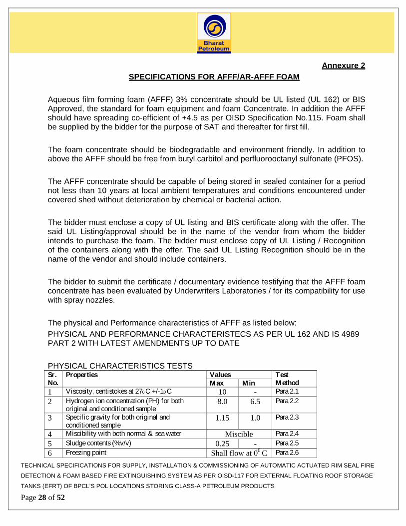
The bidder to submit the certificate / documentary evidence testifying that the AFFF foam concentrate has been evaluated by Underwriters Laboratories / for its compatibility for use with spray nozzles. The physical and Performance characteristics of AFFF as listed below: PHYSICAL AND PERFORMANCE CHARACTERISTECS AS PER UL 162 AND IS 4989 PART 2 WITH LATEST AMENDMENTS UP TO DATE PHYSICAL CHARACTERISTICS TESTS Sr. No.
Properties Values Test Method Max Min
1 Viscosity, centistokes at 270 C +/-10 C 10 - Para 2.1 2 Hydrogen ion concentration (PH) for both
original and conditioned sample 8.0 6.5 Para 2.2
3 Specific gravity for both original and conditioned sample
1.15 1.0 Para 2.3
4 Miscibility with both normal & sea water Miscible Para 2.4 5 Sludge contents (%v/v) 0.25 - Para 2.5 6 Freezing point Shall flow at 00 C Para 2.6
TECHNICAL SPECIFICATIONS FOR SUPPLY, INSTALLATION & COMMISSIONING OF AUTOMATIC ACTUATED RIM SEAL FIRE
DETECTION & FOAM BASED FIRE EXTINGUISHING SYSTEM AS PER OISD-117 FOR EXTERNAL FLOATING ROOF STORAGE
TANKS (EFRT) OF BPCL’S POL LOCATIONS STORING CLASS-A PETROLEUM PRODUCTS
Page 28 of 52
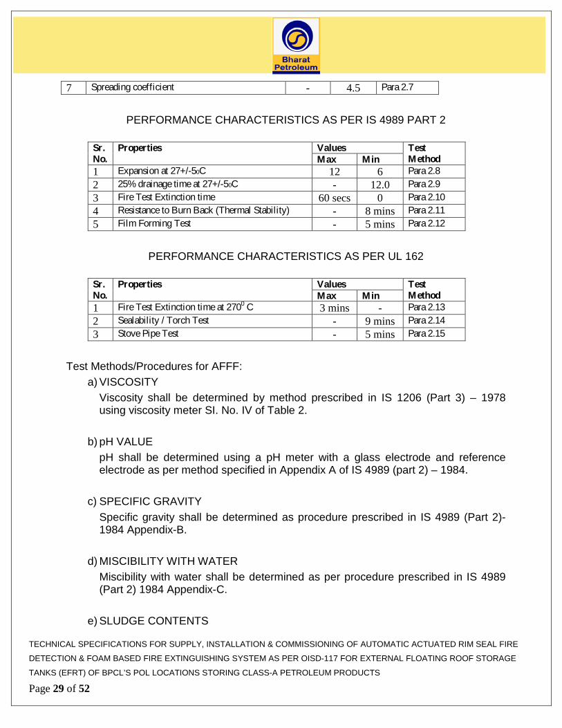
7 Spreading coefficient - 4.5 Para 2.7
PERFORMANCE CHARACTERISTICS AS PER IS 4989 PART 2
Sr. No.
Properties Values Test Method Max Min
1 Expansion at 27+/-50C 12 6 Para 2.8 2 25% drainage time at 27+/-50C - 12.0 Para 2.9 3 Fire Test Extinction time 60 secs 0 Para 2.10 4 Resistance to Burn Back (Thermal Stability) - 8 mins Para 2.11 5 Film Forming Test - 5 mins Para 2.12
PERFORMANCE CHARACTERISTICS AS PER UL 162
Sr. No.
Properties Values Test Method Max Min
1 Fire Test Extinction time at 2700 C 3 mins - Para 2.13 2 Sealability / Torch Test - 9 mins Para 2.14 3 Stove Pipe Test - 5 mins Para 2.15
Test Methods/Procedures for AFFF:
a) VISCOSITY Viscosity shall be determined by method prescribed in IS 1206 (Part 3) – 1978 using viscosity meter SI. No. IV of Table 2.
b) pH VALUE
pH shall be determined using a pH meter with a glass electrode and reference electrode as per method specified in Appendix A of IS 4989 (part 2) – 1984.
c) SPECIFIC GRAVITY
Specific gravity shall be determined as procedure prescribed in IS 4989 (Part 2)- 1984 Appendix-B.
d) MISCIBILITY WITH WATER
Miscibility with water shall be determined as per procedure prescribed in IS 4989 (Part 2) 1984 Appendix-C.
e) SLUDGE CONTENTS
TECHNICAL SPECIFICATIONS FOR SUPPLY, INSTALLATION & COMMISSIONING OF AUTOMATIC ACTUATED RIM SEAL FIRE
DETECTION & FOAM BASED FIRE EXTINGUISHING SYSTEM AS PER OISD-117 FOR EXTERNAL FLOATING ROOF STORAGE
TANKS (EFRT) OF BPCL’S POL LOCATIONS STORING CLASS-A PETROLEUM PRODUCTS
Page 29 of 52

Sludge contents shall be determined as per procedure prescribed in IS 4989 (Part 2)- 1984 Appendix-D.
f) FREEZING POINT
Freezing point shall be determined as per procedure prescribed in IS 4989 (Part 2) 1984 APPENDIX-E
g) SPREADING COEFFICIENT
Spreading coefficient shall be determined as per formula/method described in IS 4989 (Part 2) - 1984 Appendix –H-valve as per OISD 115.
h) EXPANSION
Expansion of the foam shall be determined as per procedure prescribed in IS 4989 (Part 2) 1984 – Appendix – J.
i) 25% DRAINAGE TIME
25% drainage time shall be determined as per procedure prescribed in IS 4989 (Part 2) 1984 Appendix- K
j) FIRE TEST EXTINGUISHMENT TIME
Fire test extinguishments shall be determined as per procedure prescribed in IS 4989 (Part 2) – 1984 Appendix – L
k) RESISTANCE TO BURN BACK
Resistance to burn back shall be determined as per procedure prescribed in IS 4989 (Part2) –1984 Appendix – M.
l) FILM FORMING
Film forming test shall be determined as per procedure prescribed in IS 4989 (Part 2) 1984 Appendix –G
m) FIRE TEST AS PER UL 162 Fire pan size and shape: 50 Sq.Ft.(4.65 Sq.Mtr) (LxBxH) (L=7.07 ft.., B=7.07ft, H=11inch.min) Fuel Type: Haptane Qty: 243 Ltrs.
TECHNICAL SPECIFICATIONS FOR SUPPLY, INSTALLATION & COMMISSIONING OF AUTOMATIC ACTUATED RIM SEAL FIRE
DETECTION & FOAM BASED FIRE EXTINGUISHING SYSTEM AS PER OISD-117 FOR EXTERNAL FLOATING ROOF STORAGE
TANKS (EFRT) OF BPCL’S POL LOCATIONS STORING CLASS-A PETROLEUM PRODUCTS
Page 30 of 52
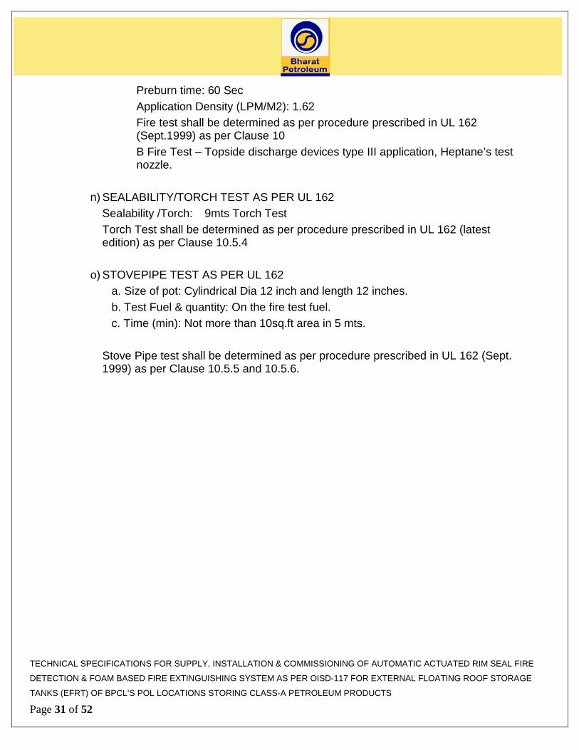
Preburn time: 60 Sec Application Density (LPM/M2): 1.62
Fire test shall be determined as per procedure prescribed in UL 162 (Sept.1999) as per Clause 10 B Fire Test – Topside discharge devices type III application, Heptane’s test nozzle.
n) SEALABILITY/TORCH TEST AS PER UL 162 Sealability /Torch: 9mts Torch Test
Torch Test shall be determined as per procedure prescribed in UL 162 (latest edition) as per Clause 10.5.4
o) STOVEPIPE TEST AS PER UL 162
a. Size of pot: Cylindrical Dia 12 inch and length 12 inches. b. Test Fuel & quantity: On the fire test fuel. c. Time (min): Not more than 10sq.ft area in 5 mts.
Stove Pipe test shall be determined as per procedure prescribed in UL 162 (Sept. 1999) as per Clause 10.5.5 and 10.5.6.
TECHNICAL SPECIFICATIONS FOR SUPPLY, INSTALLATION & COMMISSIONING OF AUTOMATIC ACTUATED RIM SEAL FIRE
DETECTION & FOAM BASED FIRE EXTINGUISHING SYSTEM AS PER OISD-117 FOR EXTERNAL FLOATING ROOF STORAGE
TANKS (EFRT) OF BPCL’S POL LOCATIONS STORING CLASS-A PETROLEUM PRODUCTS
Page 31 of 52

ANNEXURE-3 SPECIFICATIONS FOR ELECTRICAL ITEMS & CABLES :
1. SPECIFICATION FOR EXPLOSION / FLAMEPROOF JUNCTION BOX
1 Body & Cover Cast Al. Alloy (LM-6); minimum 5 mm thick. 2 Gasket Neoprene rubber
3 Terminals Clip on type, block locked at both ends suitable for up to 2.5 mm2 conductor.
4 Tag nameplate to be provided
5 Paint Anti corrosive epoxy paint, shade light gray
6 Protection class
Flameproof – Ex d Zone 1 & 2, Group IIA, IIB as per IS 2148, T6 & IP 65 to IS 13947/93, PESO (CCOE) approval
7 Other
Flameproof junction box shall have detachable cover, which is fixed, to the box by means of cadmium plated hexagonal head screws. Terminal shall be spring loaded; vibration proof, clip-on type, mounted on nickel plated steel rails complete with end cover and clamps for each row. Sizing shall be done with due consideration for accessibility and maintenance in accordance with the following guidelines: • Two Terminal strips consisting of 24 terminals shall be
provided • 50 to 60 mm gap between terminal strips and sides of box
parallel to terminals strip , • 50 to 60 mm gap between two parallel terminal strips. • Bottom/ top of terminal strips shall not be less than 100 mm
from bottom/top of the Junction Box All junction boxes shall be provided with external earthing lugs. All junction boxes shall be provided with 20% spare cable entries and terminals. Each junction box shall have a minimum of 10% or 2 Nos. whichever are higher, spare entries. All spare entries shall be with Ex d plugs. Flameproof / WP Double compression type SS cable glands /Plugs shall be provided by vendor. All the cable glands shall be preferably NPT with PVC hoods unless otherwise specified.
TECHNICAL SPECIFICATIONS FOR SUPPLY, INSTALLATION & COMMISSIONING OF AUTOMATIC ACTUATED RIM SEAL FIRE
DETECTION & FOAM BASED FIRE EXTINGUISHING SYSTEM AS PER OISD-117 FOR EXTERNAL FLOATING ROOF STORAGE
TANKS (EFRT) OF BPCL’S POL LOCATIONS STORING CLASS-A PETROLEUM PRODUCTS
Page 32 of 52

8 Cable Entry Shall have min. 12 side entry points(1/2” or ¾ “) for 2C x 1.5 mm2 cable and 1 bottom entry (1½”) for Multicore cable ( 24C x 1.5mm2)
Manual Actuation Point (MAP)
No. Description Specification A. Mechanical Data 1 Type One push button actuated with mushroom head 2 Material Aluminum LM6 with safety glass 3 Protection Flameproof – Exd Zone 1 & 2, Group IIA, IIB as
per IS 2148, T6 & IP 65 to IS 13947/93, PESO (CCOE) approval
4 No. of contacts 2 NO + 2 NC. 5 Contact Rating 230V AC, 5A 6 Gasket Neoprene
2. CABLES :
Power and Control cables shall be 1100 / 660 V grade. Multi stranded copper conductor. PVC insulated, PVC inner extruded sheathed, GI wire / Strip armoured and FRLS PVC outer sheathed confirming to IS 1554. Signal cable shall be with multi stranded copper conductor. PVC insulated 2 cores twisted to form a pair, shielded with an aluminium Mylar tape along with multi-strand bare tinned annealed copper drain wire pair laid up together overall shielded with aluminium Mylar tape, PVC inner sheath, galvanized wire armoured and overall FRLS PVC outer sheathed as per IS 5831. Sequential marking on outer sheath to be provided at an interval of 1 M.
2.1. SIGNAL CABLE Type of cable Single pair/ Multi-pair shielded copper cable. Construction Min. 1.5 mm2, 7/0.43 strand annealed tinned electrolytic
copper as per IS 8130/84 Primary insulation
PVC compound type ST2. Thickness - 0.6 mm (minimum) extruded PVC as per IS 5831 type C
Pair twist Two cores of the pair shall be twisted. Ten number of twist per meter shall be minimum
TECHNICAL SPECIFICATIONS FOR SUPPLY, INSTALLATION & COMMISSIONING OF AUTOMATIC ACTUATED RIM SEAL FIRE
DETECTION & FOAM BASED FIRE EXTINGUISHING SYSTEM AS PER OISD-117 FOR EXTERNAL FLOATING ROOF STORAGE
TANKS (EFRT) OF BPCL’S POL LOCATIONS STORING CLASS-A PETROLEUM PRODUCTS
Page 33 of 52

Shield (Individual Pair)
Each pair shall be shielded with aluminium backed Mylar, tape with 100 % coverage and minimum 25 % overlap.
Shield (Multi-pair)
Same as above for individual pair shielding. Also the overall shield shall be of aluminium backed Mylar tape with 100 % coverage and minimum 25 % overlap.
Shield thickness Min. 0.05 mm for individual and overall shielding Inner Jacket Extruded PVC, type ST2 ,
Thickness – 0.7 mm Outer Jacket Extruded PVC, type ST2, FRLS, Blue colour
Thickness – 1.4 mm (min) Pair identification
As per BS:5308 ( Table 11)
Rip cord Shall be provided Drain wire 0.5 sq. mm multi-strand bare tinned copper conductor in a
continuous contact with aluminium side of the shield shall be provided,
Armour Armour over inner jacket shall be of Galvanized steel wire as per IS 1554. Part I
Electrical characteristics
Maximum resistance of the conductor of the complete cable shall not exceed 12.3 ohm/Km at 20-deg. C Mutual capacitance of the adj. cores or pair shall not exceed a max. Of 250 nF/Km at a frequency of 1 kHz. Capacitance between any core and screen shall not exceed 400 pF/m at a frequency of 1 kHz. L/R ratio shall not exceed 40 micro henries per ohm.
2.2 POWER CABLE Type of cable XLPE (FRLS) insulated armoured Cable Construction Size as per actual design, multi stranded annealed bare
electrolytic grade copper conductor. Voltage Rating Up to and including 1100 volts Primary insulation
Extruded PVC compound as per IS 5831 type A
Inner Sheath Extruded PVC compound type STI, min thickness as per table 4 of IS 1554 Part (I)
Outer Sheath XLPE, Colour black, FRLS (Fire Retardant Low Smoke ),
TECHNICAL SPECIFICATIONS FOR SUPPLY, INSTALLATION & COMMISSIONING OF AUTOMATIC ACTUATED RIM SEAL FIRE
DETECTION & FOAM BASED FIRE EXTINGUISHING SYSTEM AS PER OISD-117 FOR EXTERNAL FLOATING ROOF STORAGE
TANKS (EFRT) OF BPCL’S POL LOCATIONS STORING CLASS-A PETROLEUM PRODUCTS
Page 34 of 52

Oxygen index of 29 at 27 (+/- 2) deg C. Armour over inner sheath
Galvanized steel wire for UAD less than 13 mm, Galvanised steel strip for UAD greater than 13 mm Dimensions as per table 5 of IS 1554 Part I
Core identification
2 Core : Red & Black 3 Core : Red, Yellow & Blue
Note: Extra core to be considered for purpose of internal earthing of FLP equipment
2.3 CONTROL CABLE Type of Cable PVC (FRLS) insulated armoured Cable Cable Size • Branch Cable - 3C x 1.5 mm2
• Multicore Cable- 24C x 1.5mm2 Construction Solid bright annealed electrolytic copper conductor insulated
and sheathed as per IS-8130. Multi stranded annealed bare electrolytic grade copper conductor
Primary Insulation
Extruded PVC compound as per IS 5381 type C. Min thickness as per IS.
Inner Sheath Extruded PVC compound, type ST2, Min thickness as per IS 5831
Outer Sheath Extruded PVC compound, type ST2, Min thickness as per IS, FRLS (Fire Retardant Low Smoke ), Black Colour.
Armour Shall be provided of galvanized steel wire/flat strip (1.4mm wire for 2-pair and 4 x 0.8mm strip for multi-pair)
Electrical Characteristics
Max. Resistance of the conductor of the cable shall not exceed 12.4 ohm/km at 20 deg. C
Voltage Class Up to & including 1100V Core Identification
Core Identification number shall be provided at a distance of not more than 1m
3.0 Specification FOR G.I. CABLE TRAYS & ACCESSORIES
Codes IS 1079 Hot Rolled Carbon Steel & Strip IS 816 Code of practice for use metal arc welding for
general TECHNICAL SPECIFICATIONS FOR SUPPLY, INSTALLATION & COMMISSIONING OF AUTOMATIC ACTUATED RIM SEAL FIRE
DETECTION & FOAM BASED FIRE EXTINGUISHING SYSTEM AS PER OISD-117 FOR EXTERNAL FLOATING ROOF STORAGE
TANKS (EFRT) OF BPCL’S POL LOCATIONS STORING CLASS-A PETROLEUM PRODUCTS
Page 35 of 52

IS 2629 Recommended practice for hot dip galvanizing of iron & steel
IS 2633 Method of testing, uniformity of coating on zinc coated articles
Indian Electricity Act & Indian Electricity Rules Tray & Accessories Type Perforated Width As Specified Standard Length 2500mm Thickness 2.5mm Height 50mm Support Span 2500mm Hardware Nuts, Bolts, Washers
Electrogalvanised / Zinc Passivated
Coupler Plate Perforated Type 2.5mm Sizes As per Installation Standards Coupler Plates shall be provided with necessary fixing hardware Coating Coating Thickness 65 micron Zinc Deposit 460 gms/sq. mtr Makes Indiana / Profab / Anand Udyog / Superfab
4.0 STANDARD SPECIFICATION / PROCEDURE FOR CABLE LAYING
a. Armoured power, control & signalling cables shall laid above ground on G.I. Cable trays or directly buried under soil / through HDPE pipes as per approved drawings.
b. In direct burial, cable trenches shall be prepared by earthwork in excavation in all
types of soils and across roads, dykes etc. as required. The automation vendor shall carry out all the necessary shoring, strutting and bailing of water wherever required. The trench shall be kept dry. The trench bottom shall be rammed, levelled and back filled with a layer of fine river sand.
c. The entire cable length has to be laid overhead or on pedestals except where there
is no other alternative but to lay the cable underground through Hume pipes /
TECHNICAL SPECIFICATIONS FOR SUPPLY, INSTALLATION & COMMISSIONING OF AUTOMATIC ACTUATED RIM SEAL FIRE
DETECTION & FOAM BASED FIRE EXTINGUISHING SYSTEM AS PER OISD-117 FOR EXTERNAL FLOATING ROOF STORAGE
TANKS (EFRT) OF BPCL’S POL LOCATIONS STORING CLASS-A PETROLEUM PRODUCTS
Page 36 of 52
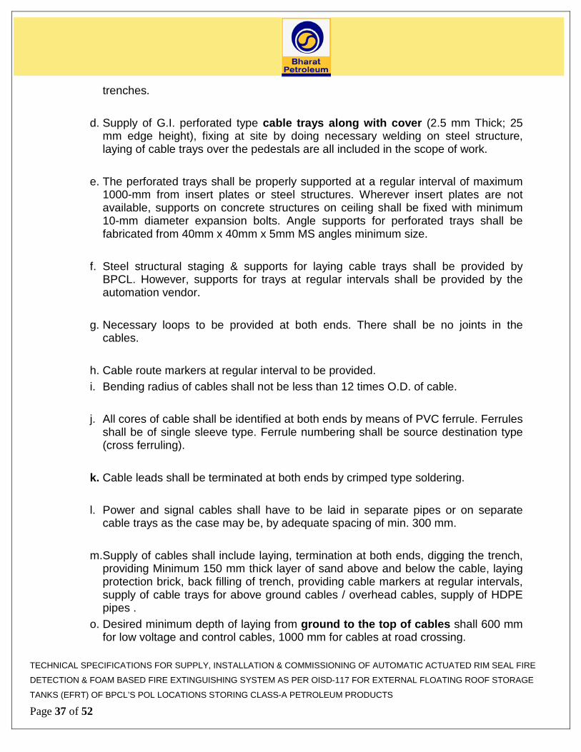
trenches. d. Supply of G.I. perforated type cable trays along with cover (2.5 mm Thick; 25
mm edge height), fixing at site by doing necessary welding on steel structure, laying of cable trays over the pedestals are all included in the scope of work.
e. The perforated trays shall be properly supported at a regular interval of maximum
1000-mm from insert plates or steel structures. Wherever insert plates are not available, supports on concrete structures on ceiling shall be fixed with minimum 10-mm diameter expansion bolts. Angle supports for perforated trays shall be fabricated from 40mm x 40mm x 5mm MS angles minimum size.
f. Steel structural staging & supports for laying cable trays shall be provided by
BPCL. However, supports for trays at regular intervals shall be provided by the automation vendor.
g. Necessary loops to be provided at both ends. There shall be no joints in the
cables. h. Cable route markers at regular interval to be provided. i. Bending radius of cables shall not be less than 12 times O.D. of cable. j. All cores of cable shall be identified at both ends by means of PVC ferrule. Ferrules
shall be of single sleeve type. Ferrule numbering shall be source destination type (cross ferruling).
k. Cable leads shall be terminated at both ends by crimped type soldering. l. Power and signal cables shall have to be laid in separate pipes or on separate
cable trays as the case may be, by adequate spacing of min. 300 mm. m. Supply of cables shall include laying, termination at both ends, digging the trench,
providing Minimum 150 mm thick layer of sand above and below the cable, laying protection brick, back filling of trench, providing cable markers at regular intervals, supply of cable trays for above ground cables / overhead cables, supply of HDPE pipes .
o. Desired minimum depth of laying from ground to the top of cables shall 600 mm for low voltage and control cables, 1000 mm for cables at road crossing.
TECHNICAL SPECIFICATIONS FOR SUPPLY, INSTALLATION & COMMISSIONING OF AUTOMATIC ACTUATED RIM SEAL FIRE
DETECTION & FOAM BASED FIRE EXTINGUISHING SYSTEM AS PER OISD-117 FOR EXTERNAL FLOATING ROOF STORAGE
TANKS (EFRT) OF BPCL’S POL LOCATIONS STORING CLASS-A PETROLEUM PRODUCTS
Page 37 of 52

p. Wherever the cables have to cross the asphalt roads, the rate quoted shall include cutting of the asphalt and WBM roads including soling and necessary excavation to the required depth and back filling the trench with river sand and restoring the asphalt / WBM roads to its original condition including compacting and rolling the surface shall be arranged by the vendor.
q. Wherever underground conduits are provided by other contractor & if space is
available than automation vendor shall lay cables in conduit without any additional cost.
r. Separate cable tray shall be used for laying Power & Signal / Communication / Control Cables.
s. The cables shall be laid with min. spacing of “D” (D being the diameter of the
thicker cable) * 15mm from edge of the cable tray. Power Cable shall be laid in separate trench and Signal & Communication Cabling shall be laid different trench. The same may be laid in common trench provided physical barrier in the form of bricks are provided in such a way that both are laid min 300mm apart. Power & Signal / Communication / Control Cables shall be laid separately.
t. Wherever the cables have to cross the asphalt roads, the job shall include cutting
of the asphalt and WBM roads including soiling and necessary excavation to the required depth and back filling the trench with river sand and restoring the asphalt / WBM roads to its original condition including compacting and rolling the surface.
u. All the cables be neatly clamped on the cable tray and loose hanging cables shall
not be allowed. v. Required loops shall be provided at both ends of the main cables. Cable shall be
laid without any joints. w. Cable route markers at 20m/c and at all the bends/turnings shall be provided. x. Bending radius of cables shall not be less than 12times O.D. of cable. y. All cores of cable shall be identified at both ends by means of PVC ferrule. z. Line drivers & all other accessories required in this regard are included in the
scope of work of the vendor.
aa. Cable laying shall also include termination of cables at both the ends. Cable leads shall be terminated at both ends by crimped type soldering.
TECHNICAL SPECIFICATIONS FOR SUPPLY, INSTALLATION & COMMISSIONING OF AUTOMATIC ACTUATED RIM SEAL FIRE
DETECTION & FOAM BASED FIRE EXTINGUISHING SYSTEM AS PER OISD-117 FOR EXTERNAL FLOATING ROOF STORAGE
TANKS (EFRT) OF BPCL’S POL LOCATIONS STORING CLASS-A PETROLEUM PRODUCTS
Page 38 of 52

bb. Rate shall also include megger test by 1000V megger for establishing the healthiness of cable in the drum before removing the same, unwinding and straightening the cable & after laying of cables.
5.0 Painting
a. This part of the specification is applicable to CS impulse pipes, instrument supports and all other structural supports for cable trays, ducts, impulse tubes, airlines etc.
b. The surface to be painted shall be thoroughly cleaned with wire brush, sandpaper to remove all scales. After cleaning, the surface is painted with one coat of red oxide zinc chromate primer conforming to IS 1074 and allowed to dry completely
c. Primer coated surface is painted with one coat of synthetic enamel paint to the
color nearest to the final paint and allowed to dry. The color number shall be from IS 5.
d. Final second coating shall be with the paint of desired colors and shall be selected
from IS 5. e. The name of manufacturer, color and quality of all types of primer paint shall be
subject to approval of BPCL.
6.0 INSPECTION, TESING AND ACCEPTANCE The cables shall be tested and inspected at the manufacturer’s works or alternatively at lab if the cables are procured from traders. All the materials employed in the manufacture of the cable shall be subjected, both before and after manufacture, to examination, testing and approval by Third Party Inspection. Manufacturer shall furnish all necessary information concerning the supply to BPCL. After completion of manufacture of cables and prior to dispatch, the cables shall be subjected to type, routine, acceptance and special tests as detailed below. BPCL reserves the right to witness all test with sufficient advance notice from vendor. The test reports for all cables shall be approved from the Third Party Inspection agency before dispatch of the cables. All routine tests, acceptance tests, type tests and additional type tests for improved fire
TECHNICAL SPECIFICATIONS FOR SUPPLY, INSTALLATION & COMMISSIONING OF AUTOMATIC ACTUATED RIM SEAL FIRE
DETECTION & FOAM BASED FIRE EXTINGUISHING SYSTEM AS PER OISD-117 FOR EXTERNAL FLOATING ROOF STORAGE
TANKS (EFRT) OF BPCL’S POL LOCATIONS STORING CLASS-A PETROLEUM PRODUCTS
Page 39 of 52

performance shall be carried out as listed in IS:1554 (Part I). The test requirements for PVC insulation and sheath of cables shall be as per latest revision of IS:5831.
• Test for Resistance to Ultra Violet Radiation:- This test shall be carried out as per DIN 53387 or ASTM-G-53 on outer sheath. The retention value of tensile strength and ultimate elongation after the test shall be minimum 60% of tensile strength and ultimate elongation before the test. Test certificates with respect to this test (not older than one year) from recognized testing laboratory to be furnished for review by Third Party Inspection agency before dispatch clearance of cables. In case test certificates are not available, test is to be conducted by vendor at his own cost in any recognized test laboratory or in house testing laboratory, before dispatch clearance of cables. Sampling for this test is to be done randomly once for each order, provided outer sheath remains same.
• Acceptance test as per IS-1554 (Part 1) and the following special tests to be performed on the cables as per sampling plan. These tests are required to be witnessed by Third Party Inspection Agency before dispatch of cables. o Accelerated water absorption test for insulation as per NEMA-WC-5 (for PVC
insulated cables). Test certificate with respect to this test (not older than one year) from recognized testing laboratory to be furnished for review by Third Party Inspection Agency before dispatch clearance of cables. In case test certificates are not available, test is to be conducted by vendor at his own cost in any recognized test laboratory or in-house testing laboratory, before dispatch clearance of cables. Sampling for this test is to be done randomly once for each order, provided type of insulation remains same.
o Dielectric Retention Test :- The dielectric strength of the cable insulation tested in accordance with NEMA WC-5 at 75 +/- 1 deg C shall not be less than 50% of the original dielectric strength (for PVC insulated cables). Test certificates with respect to this test (not older than one year) from recognized testing laboratory to be furnished for review by Third Party Inspection Agency before dispatch clearance of cables. In case test certificates are not available, test is to be conducted by vendor at his own cost in any recognized test laboratory or in-house testing laboratory, before dispatch clearance of cables. Sampling for this test is to be done randomly and once for each order.
o Oxygen Index Test:- The test shall be carried out as per ASTM D2863 or applicable Indian Standard Specifications. Sampling to be done for every offered lot/size as per sampling plan.
o Flammability Test:- The test shall be carried out on finished cable as per IS-10810 (Part 61 & 62). Sampling for these tests is to be done randomly once for each order provide outer sheath remains same. The acceptance criteria for tests conducted shall be as under:-
TECHNICAL SPECIFICATIONS FOR SUPPLY, INSTALLATION & COMMISSIONING OF AUTOMATIC ACTUATED RIM SEAL FIRE
DETECTION & FOAM BASED FIRE EXTINGUISHING SYSTEM AS PER OISD-117 FOR EXTERNAL FLOATING ROOF STORAGE
TANKS (EFRT) OF BPCL’S POL LOCATIONS STORING CLASS-A PETROLEUM PRODUCTS
Page 40 of 52

Part-61:- The cable meets the requirement if there is no visible damage on the test specimen within 300mm from its upper end.
Part-62:- The maximum extent of the charred portion measured on the test sample should not have reached a height exceeding 2.5m above the bottom edge of the burner at the front of the ladder.
o Test for rodent and termite repulsion property. The vendors shall furnish the test details to analyze the property by chemical method. Sampling to be done for every offered lot / size as per sampling plan.
In case the cables are purchased through Traders the same shall be sent to lab for testing purpose.
Earthing Each panel, cabinet and other equipment in control room shall be provided with an earthing lug. All these lugs shall be properly secured to the AC mains earthing bus. The earthing cables from the earth-pit to the respective systems shall be insulated and use of bare cable / strips shall be avoided.
EARTH PITS Separate earth pits shall be provided for system earth, IS earth, power earth, and general body earth for instruments, equipments, junction box body etc. These earth pits shall be separate and isolated from electrical earth pits. Earth pit resistance and exact no. of earth pits/electrodes shall be considered based on the PLC, TFMS & other instrument’s manufacture’s requirements and recommendation. For system earth redundant earth pit shall be provided. Both earth pits shall be connected to form ring loop.
Instrument Grounding System In principle, grounding earth for instruments shall be provided in compliance with instrument manufacturer's recommendation. However, two independent earth pits shall be provided for following:
Signal Earth: Low voltage/IS signals (Shield) etc shall be connected to this earth. Grounding shall have 1 ohms or less than 1 ohms earth resistance unless otherwise recommended by System manufacture. When recommended by system manufacturer for independent earth pit it shall be provided as specified.
Power Earth: The frame of Panels/cabinets/junction boxes, instrument body etc. shall be connected to this earth. Power earth for high voltage level of 240 /110VAC
TECHNICAL SPECIFICATIONS FOR SUPPLY, INSTALLATION & COMMISSIONING OF AUTOMATIC ACTUATED RIM SEAL FIRE
DETECTION & FOAM BASED FIRE EXTINGUISHING SYSTEM AS PER OISD-117 FOR EXTERNAL FLOATING ROOF STORAGE
TANKS (EFRT) OF BPCL’S POL LOCATIONS STORING CLASS-A PETROLEUM PRODUCTS
Page 41 of 52

shall be connected to this grounding. Earth resistance shall be 5 ohms or less than 5 ohms for standard electrical earth pits in this project.
TECHNICAL SPECIFICATIONS FOR SUPPLY, INSTALLATION & COMMISSIONING OF AUTOMATIC ACTUATED RIM SEAL FIRE
DETECTION & FOAM BASED FIRE EXTINGUISHING SYSTEM AS PER OISD-117 FOR EXTERNAL FLOATING ROOF STORAGE
TANKS (EFRT) OF BPCL’S POL LOCATIONS STORING CLASS-A PETROLEUM PRODUCTS
Page 42 of 52
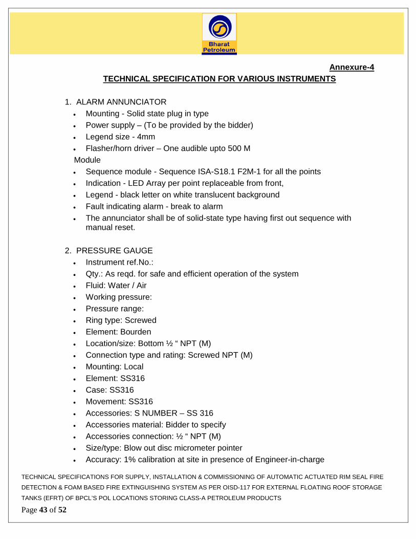
Annexure-4 TECHNICAL SPECIFICATION FOR VARIOUS INSTRUMENTS
1. ALARM ANNUNCIATOR
• Mounting - Solid state plug in type • Power supply – (To be provided by the bidder) • Legend size - 4mm • Flasher/horn driver – One audible upto 500 M
Module • Sequence module - Sequence ISA-S18.1 F2M-1 for all the points • Indication - LED Array per point replaceable from front, • Legend - black letter on white translucent background • Fault indicating alarm - break to alarm • The annunciator shall be of solid-state type having first out sequence with
manual reset. 2. PRESSURE GAUGE
• Instrument ref.No.: • Qty.: As reqd. for safe and efficient operation of the system • Fluid: Water / Air • Working pressure: • Pressure range: • Ring type: Screwed • Element: Bourden • Location/size: Bottom ½ “ NPT (M) • Connection type and rating: Screwed NPT (M) • Mounting: Local • Element: SS316 • Case: SS316 • Movement: SS316 • Accessories: S NUMBER – SS 316 • Accessories material: Bidder to specify • Accessories connection: ½ “ NPT (M) • Size/type: Blow out disc micrometer pointer • Accuracy: 1% calibration at site in presence of Engineer-in-charge
TECHNICAL SPECIFICATIONS FOR SUPPLY, INSTALLATION & COMMISSIONING OF AUTOMATIC ACTUATED RIM SEAL FIRE
DETECTION & FOAM BASED FIRE EXTINGUISHING SYSTEM AS PER OISD-117 FOR EXTERNAL FLOATING ROOF STORAGE
TANKS (EFRT) OF BPCL’S POL LOCATIONS STORING CLASS-A PETROLEUM PRODUCTS
Page 43 of 52

• Enclosure type: Weatherproof, IP 55 3. PRESSURE SWITCH
• Qty. required: As reqd. for safe and efficient operation the system • Service Fluid: Water /Air • Working pressure:As per design of the vendor • Working temperature: Ambient • Element type: Bellows • Element material: SS 316 • Connection size and type: ½ “ NPT(F) • Location: Bottom • Over range (max.op.pr): • Set point: as per design requirements • Switch type: Snap acting micro switch • Switch action: Opens on low pressure condition • Accuracy: 0.5% • Cable entry/size: ½ “ NPTF • Enclosure type: Weather proof, IP 65, Ex (d) • Setting adjustment: 10% to 90% • Gland type: Weather proof • Mounting: Direct with brackets • Alarm contacts, rating: SPDT, 5A • Case material: Die cast Aluminium • Calibration: Calibration at site in presence of engineer-in-charge
4. JUNCTION BOX SPECIFICATION
• Type: For connecting cables from individual instruments • Enclosure: Explosion proof (Ex(d)), W/P IP65 • Mounting: Bracket / pedestal mounting • Entries: As per requirement • Cable glands: Adequate double compression cable glands to be provided • Earthing terminal: Required • Drain fittings: Required • Tag plate: Non corrosive SS tag plate
TECHNICAL SPECIFICATIONS FOR SUPPLY, INSTALLATION & COMMISSIONING OF AUTOMATIC ACTUATED RIM SEAL FIRE
DETECTION & FOAM BASED FIRE EXTINGUISHING SYSTEM AS PER OISD-117 FOR EXTERNAL FLOATING ROOF STORAGE
TANKS (EFRT) OF BPCL’S POL LOCATIONS STORING CLASS-A PETROLEUM PRODUCTS
Page 44 of 52

5. SOLENIOD VALVE • Coil Voltage: To be provided by the Bidder • Coil insulation: Class H • Enclosure: Weather proof to IP 65 • Ex. Proof required: Yes, Ex(d) required • Body & Trim of the valve: SS 316 • Seat: SS 316 • Disc: Teflon • Seal: Teflon • Port type: 3 way • No. of coil: single • Pneumatic connection: ¼” NPT(F) • Cable entry: ½”NOT(F) • Accessories: Bug proof on vent port SS cable gland
5. Graphic Console : 1. Make DELL / HP / IBM 2. Model To be furnished by vendor 3. Processor Intel Core i5-760 processor(2.8 GHz,
1333Mhz FSB, 8 MB cache) 4. Processor cache 6 MB Advanced Transfer Cache 5. RAM 6 GB DDR3 SDRAM 6. Hard Disk Drive 500 GB SATA 3.0Gb/s 7. Optical Drive Single drive: Blu-ray Disc Combo (DVD+/-
RW+NABRCBO BD-ROM) 8. Video Card In Built – ATI Radeon HD5770 1GB 9. Sound Card Integrated high definition 7.1 channel audio 10. Speaker Multimedia Desktop speaker system 11. Graphics Subsystem
NVIDA Quadro Graphics card for supporting high resolution images
12. Keyboard Minimum 104 keys 13. Mouse Optical 14. Built In I/O Ports 1 serial; keyboard; mouse; 2 USB
10/100/1000 Base -TX Redundant LAN Interface
TECHNICAL SPECIFICATIONS FOR SUPPLY, INSTALLATION & COMMISSIONING OF AUTOMATIC ACTUATED RIM SEAL FIRE
DETECTION & FOAM BASED FIRE EXTINGUISHING SYSTEM AS PER OISD-117 FOR EXTERNAL FLOATING ROOF STORAGE
TANKS (EFRT) OF BPCL’S POL LOCATIONS STORING CLASS-A PETROLEUM PRODUCTS
Page 45 of 52

Quad Card for expansion of monitoring screens
15. Ethernet Dual integrated 10/100/1000 Mbps Ethernet 16.
Monitor
21.5" Full HD Wide screen Flat panel with provision to accept input from two work stations with toggle button to select the work station.
17 Operating System Microsoft Windows 7 Professtional 18 Software Microsoft office 2010 19 Antivirus program Required
7.0 Specifications for MAIN RIM SEAL FIRE ALARM PANEL
a. Panel shall be of freestanding, enclosed type and shall be designed for bottom
entry for cable connection. Panel’s structure shall be sound and rigid and shall be provided with removable lifting lugs to permit lifting of the panels.
b. Panel shall be fabricated from cold rolled steel sheet of minimum 2-mm thickness suitably reinforced to prevent warping and buckling. Doors shall be fabricated from cold rolled steel sheet of minimum 1.6 mm thickness. Panel shall be thoroughly deburred and all sharp edges shall be grounded smooth after fabrication.
c. Panel shall be of maximum 2100-mm height and 800 mm width. d. Painting of Control Panels shall be oven baked (2 primer coats and 2 final coats)
powder coating, with matt finish. The colour scheme is as below- e. Panel Exterior – Light Grey (RAL 7035) f. Panel Interior- Pale Yellow g. A 100mm channel base is to be provided at the bottom for mounting the Control
Panel. Shade shall be Light Grey (RAL 7035). h. Control Panel-Front, shall be provided with cut-outs for Flush mounting of Alarm
Annunciator & Accessories. i. Control Panel – Rear, shall be equipped with access doors. Doors shall be
equipped with lockable handles and concealed hinges with pull pins for each door removal.
j. In order to effectively remove dissipated heat from the panels, vent louvers backed by wire fly screen shall be provided to panel doors. Two nos. each i.e. total four nos. of ventilation fans shall be provided for front & rear portions of the panel.
k. Illumination shall be provided for all panels by CFL/ LED Lamps and door operated micro switches. Utility socket of the rated power supply shall be provided.
l. Equipment, within the panel, shall be laid out in an accessible and logically
TECHNICAL SPECIFICATIONS FOR SUPPLY, INSTALLATION & COMMISSIONING OF AUTOMATIC ACTUATED RIM SEAL FIRE
DETECTION & FOAM BASED FIRE EXTINGUISHING SYSTEM AS PER OISD-117 FOR EXTERNAL FLOATING ROOF STORAGE
TANKS (EFRT) OF BPCL’S POL LOCATIONS STORING CLASS-A PETROLEUM PRODUCTS
Page 46 of 52

segregated manner. Clamping rails shall be provided for incoming cables to prevent excessive stress on the individual terminal. All metal parts of the panel including doors shall be electrically continuous and shall be provided with a common grounding lug.
m. Terminals Blocks and wiring
1. Termination blocks shall be of clip-on type mountable on standard rails. They shall be of shrouded type with slot for screwdriver. TB shall be of stacking type.
2. Wherever needed, fused TB with adequate rated fuse shall be provided. 3. Terminal blocks shall be so located that there is proper accessibility. 4. Terminal Blocks for 230 V AC and 24 V DC shall be of different colours. There
shall be CAUTION plate with plastic holding screws. 5. Single terminals shall not be used for terminating more than 2 wires. 6. Terminal blocks shall carry identification marks on each of them. 7. At least 20% extra terminals shall be provided. 8. Panel wiring shall be neat and tidy, confirming to the engineering practice
existing. 9. 1100 volts grade, PVC insulated, multi strand, single core cable shall be used
as per specification. 10. Cable size of minimum 0.5 sq. mm to 2.5 sq. mm or higher size depends on the
current rating. 11. Recommended colour codes for wires
• 230 V Phase Red • 230 V Neutral Black • 230 V Ground Green
12. All cables shall be routed through good quality rectangular cable ducts. Cables shall occupy only up to 60% of duct area.
13. Wire termination shall be made with solder less crimping type tinned copper lugs of suitable shape such as bootlace, spade, etc., which shall firmly grip conductor and insulation. Sleeves shall be provided for all wire termination.
14. All cables shall be properly marked at both ends using ferrules. These ferrules shall be printed on an electronic machine using a single PVC sleeve. At each end target and source code shall be described.
n. Breakers and Fuses:
All electrical circuits shall be fed from moulded case circuit breakers, installed in the “line” lead, using separate breaker for each circuit. Neutrals may be bussed but must be identified with the associated circuit breaker.
TECHNICAL SPECIFICATIONS FOR SUPPLY, INSTALLATION & COMMISSIONING OF AUTOMATIC ACTUATED RIM SEAL FIRE
DETECTION & FOAM BASED FIRE EXTINGUISHING SYSTEM AS PER OISD-117 FOR EXTERNAL FLOATING ROOF STORAGE
TANKS (EFRT) OF BPCL’S POL LOCATIONS STORING CLASS-A PETROLEUM PRODUCTS
Page 47 of 52

Each type of power supply (230 V AC, 50Hz) of each section shall be isolated by means of adequately rated single pole thermal magnetic circuit breaker.
Circuit breaker shall be of the miniature thermal magnetic type and shall be of plug in construction (supply with plug in terminal block)
Current trip rating shall be selected to protect the load as applicable, for instrument supply generally 0.5A (assumed), common circuit breaker is to be provided to switch on and off the AC supply of the control system.
Individual circuit breaker shall be provided for each instrument shelf or group of shelves and digital indicators on mimic.
o. Earthing : 1. The Instrument Control panel in the planning room shall be provided with an
earthing lug. All these lugs shall be properly secured to the AC mains earthing bus.
2. All circuit grounds of electronic instruments, shields and drain wires of control cables shall be connected to instrument ground bus, which is electrically isolated from the AC mains earthing bus. This bus shall be typically 25 mm wide and 6 mm thick of copper. The instrument ground bus is connected to independent instrument system ground buses through insulated wires.
3. All safety Isolator shall be securely grounded. The Isolator ground wire shall be capable of carrying a maximum fault level current of 0.5 ampere at 250 V R.M.S. per barrier.
p. ALARM ANNUNCIATOR : Alarm Annunciator, shall either be solid state type or microprocessor based programmable type with plug in modules, in a panel with window display with cluster LED type integral power supply. For cluster type LED display, the number of LED (8 nos.) in the cluster matrix windows shall be sufficient to provide illumination level of a last 150 lumens. The circuit shall be designed in such a way that removal/failure of LED from a window/ cluster shall not hamper functioning of that particular window/display. The annunciator lamps shall be replaceable from the front of the enclosure panel. In general, dedicated alarm logic module shall be used for each alarm input. However, when micro processor based alarm Annunciator is offered failure of one microprocessor shall not affect more than four alarm windows.
TECHNICAL SPECIFICATIONS FOR SUPPLY, INSTALLATION & COMMISSIONING OF AUTOMATIC ACTUATED RIM SEAL FIRE
DETECTION & FOAM BASED FIRE EXTINGUISHING SYSTEM AS PER OISD-117 FOR EXTERNAL FLOATING ROOF STORAGE
TANKS (EFRT) OF BPCL’S POL LOCATIONS STORING CLASS-A PETROLEUM PRODUCTS
Page 48 of 52

An interruption of power supply up to 20 msec shall not affect the functioning of unit.
1. Type Audio and Visual, solid state with plug in module
2. Mounting Flush –Panel mounted 3. Enclosure General purpose 4. Field contact voltage Potential free 5. Input power 230 V AC, 50 Hz ±5% 6. Operating System ISA-S-18.1 7. High Intensity LED 8 nos. in each window (or Standard) 8. No. of Window 16 nos. 9. Flasher Integral 10. Make /Alarm Vendor to specify
11. Type alarm Bright flashing with audio alarm ( Breaking of contact of Field Instrument shall generate the Alarm)
12. Type of reset Manual 13. Type of Acknowledgment Lamp glow but Audio silent 14. Push Button, 3 Nos. (TEST, ACK, Reset) 15. No. of hooters 1 no. Multi tone 16. Hooter enclosure General purpose
The Alarm annunciator shall be mounted on Instrument control panel & and shall be in general accordance with ISA-S 18.1. Sequence of alarms for panel display shall be:
Process alarms Process Abnormal - Lights are flashing and Horn sound Horn/light Acknowledgement button pressed -Horn silent, Light becomes steady Process returns to normal before horn & - Light flashing and Horn blowing Light Acknowledgment buttons are pressed
Audible Alarm / hooter FOR THE MAIN RIM SEAL PANEL Hooter in general, shall be solid state type with audibility of the order of 100 dB at the distance of 3 meters, the volume of which is variable an adjustable timer shall limit the duration of audible signal. Actuation of the acknowledge button on the panel shall reset
TECHNICAL SPECIFICATIONS FOR SUPPLY, INSTALLATION & COMMISSIONING OF AUTOMATIC ACTUATED RIM SEAL FIRE
DETECTION & FOAM BASED FIRE EXTINGUISHING SYSTEM AS PER OISD-117 FOR EXTERNAL FLOATING ROOF STORAGE
TANKS (EFRT) OF BPCL’S POL LOCATIONS STORING CLASS-A PETROLEUM PRODUCTS
Page 49 of 52
the Hooter.
TECHNICAL SPECIFICATIONS FOR SUPPLY, INSTALLATION & COMMISSIONING OF AUTOMATIC ACTUATED RIM SEAL FIRE
DETECTION & FOAM BASED FIRE EXTINGUISHING SYSTEM AS PER OISD-117 FOR EXTERNAL FLOATING ROOF STORAGE
TANKS (EFRT) OF BPCL’S POL LOCATIONS STORING CLASS-A PETROLEUM PRODUCTS
Page 50 of 52

Annexure-5
APPROVED SUB-VENDOR LIST Serial No
EQUIPMENTS APPROVED VENDOR
1. ALARM ANNUNCATOR
Applied Electronics Bangalore, Procon Instrumentation, IIC , Mumbai, Minilek, Toyo Electronic Corporation Japan , Insta Alarm, Aplab
2 PRESSURE GUAGE Switzer Instruments, H.Guru Instruments Odin India, Wika Instruments Wellwin Industries, Manometer(I)Ltd. Spirana Italy, Wyka Germany
3 PRESSURE SWITCH Switzer, Danfos, Honeywell, UE through, Chemtrols
4 INSTRUMENT PANEL Waves Electronics, Kochi, Megatech Controls Rittal, Pyrotech, Chemin Controls, Pondichery
5 SIGNAL CABLES Lapp Cables, TCL cables, Nicco Corporation, Associated Cables, Delton Cables, Associated Flexibles & wires Ltd Brooks Cable works, Polycab, Radiant, Universal, Incab
6 CONTROL CABLES TCL cables, Nicco Corporation, Associated Cables Delton Cables, Brooks Cable works, CCI, KEI, Torrent, Finolex, Polycab, Universal, Gemscab, Golster cables
7 SOLENOID OPERATED VALVE
ASCO HERION
8 GI CABLE TRAYS PATNY & CO / TECHNOFAB / INDIANA / SADHANA/ IDS Composites/ National Galvaniser/Vatco/Steelite/Ratan Engineering
9 Flameproof enclosure/Junction box & cable glands
Baliga Lightings, Flexpro Electricals CEAG Flameproof Controls, Ex-Protecta / Bajaj/ Sudhir Switchgears, FCG Control Gear/ FEPL/ FCG power industries, Ex Protecta, Sudhir Switch gears
10 Power cables TCL cables, Nicco Corporation, Associated Cables
Delton Cables, Brooks Cable works, CCI, KEI, TECHNICAL SPECIFICATIONS FOR SUPPLY, INSTALLATION & COMMISSIONING OF AUTOMATIC ACTUATED RIM SEAL FIRE
DETECTION & FOAM BASED FIRE EXTINGUISHING SYSTEM AS PER OISD-117 FOR EXTERNAL FLOATING ROOF STORAGE
TANKS (EFRT) OF BPCL’S POL LOCATIONS STORING CLASS-A PETROLEUM PRODUCTS
Page 51 of 52
Torrent, Finolex, Polycab, Universal, Gemscab, Golster cables
11 UPS Emerson, HiRel, Aplab, DB Electronics 12 Instrument Control
Panel Rittal, Hoffman, Pyrotech, ICA, Vero president, APW, Enclotech
13 Relays Omron, OEN, Allen Bradly, Pramount, Lzume Denki, Finder.Honeywell
14 Push buttons L&T, Siemens, C&S, GE Power, ABB, Teknic, Merlin GERIN/BCH
15 Indication Cluster LED Lamps
Binary Electronics and Electricals / Technik/ Siemens / L&T / BCH
16 Miniature Circuit Breakers
MDS / Indokopp / Siemens / G. E Power Control / Schneider Electric/ Merlin Gerin
17 Terminal Blocks Phoenix, wago, Elmex 18 Signal Isolators/
Zener Barriers MTL, P&F
19 24 V Bulk power supply unit
Lamda, Cosel, Phoenix, Siemens, Quint
Note: 1. All the ex-proof /Intrinsic items located in hazardous area shall have CMRI, BIS
and PESO certification. 2. In case of imported items the Flameproof /Intrinsic certification from following
agency shall be provided. i.e. ATEXFM/BASEEFA/PTB/KEMA/TUV etc. PESO certificate is mandatory for both Indian and imported item.
3. Only in exceptional cases at sole discretion of owner, In case the bidder intends to provide any alternate makes then prior approval of owner is required. The bidder shall provide documents proving equivalency.
TECHNICAL SPECIFICATIONS FOR SUPPLY, INSTALLATION & COMMISSIONING OF AUTOMATIC ACTUATED RIM SEAL FIRE
DETECTION & FOAM BASED FIRE EXTINGUISHING SYSTEM AS PER OISD-117 FOR EXTERNAL FLOATING ROOF STORAGE
TANKS (EFRT) OF BPCL’S POL LOCATIONS STORING CLASS-A PETROLEUM PRODUCTS
Page 52 of 52