Embed Size (px)
Citation preview
Mathematics and Computer Science 2018; 3(4): 93-99
http://www.sciencepublishinggroup.com/j/mcs
doi: 10.11648/j.mcs.20180304.13
ISSN: 2575-6036 (Print); ISSN: 2575-6028 (Online)
Heat and Mass Transfer of NH3-H2O Falling-Film Absorption on Horizontal Round Tube Banks
Nghia-Hieu Nguyen1, Hiep-Chi Le
2, *, Quoc-An Hoang
3
1Faculty of Heat & Refrigeration Engineering, Industry University of Ho Chi Minh City, Ho Chi Minh City, Vietnam 2Department of Heat & Refrigeration Engineering, Ho Chi Minh City University of Technology, VNU-HCM, Ho Chi Minh City, Vietnam 3Science Technology Office, Ho Chi Minh City University of Technology and Education, Ho Chi Minh City, Vietnam
Email address:
*Corresponding author
To cite this article: Nghia-Hieu Nguyen, Hiep-Chi Le, Quoc-An Hoang. Heat and Mass Transfer of NH3-H2O Falling-Film Absorption on Horizontal Round
Tube Banks. Mathematics and Computer Science. Vol. 3, No. 4, 2018, pp. 93-99. doi: 10.11648/j.mcs.20180304.13
Received: July 12, 2018; Accepted: July 30, 2018; Published: August 23, 2018
Abstract: The absorption process has been confirmed as the most important process in absorption refrigeration machines in
terms of improving their total efficiency. For this reason, absorber structures in general and heat and mass transfers in absorber
in particular have attracted the interest of many researchers in this field. Commonly, the falling film absorber structure is the
liquid mixture flows over tubes in a film mode. Mathematical model is developed for the falling film flowing on horizontal
round tubes absorber derived from the mathematical model of the test volume element. The two-dimensional numerical
simulation is written to solve partial differential equations predicting absorption efficiency. For evaluating the parameters
which affect the coupled heat-mass transfer as NH3-H2O diluted solution flowing over horizontal round tubes absorb NH3
vapor to become the higher concentration solution. The fields of velocity, temperature, concentration and thickness of the
falling film solution varied by the input conditions of diluted solution and cooling water temperature flowing in the tube
represented for a test volume element of the tube. The correlations which give the heat transfer coefficient and mass transfer
coefficient in the absorption process in range of solution concentration ω = 28% ÷ 31%, solution mass flow rate per unit tube
length Γ = 0.001 ÷ 0.015 kgm-1
s-1
, coolant temperature twater = 28°C ÷ 38oC are set as two functions. The accuracy of numerical
model and experiments are compared by the inlet, outlet the tube bundle of cooling water temperatures and absorber heat load.
The absorber heat load deviation of the computing program Qa_cumpute and experimental result Qa_meas is 4.3%. The absorber
heat load deviation of simulation result Qa_sim and experimental result Qa_meas is 12.3%. The overall heat transfer coefficient k
used for simulation result of absorber heat load was taken from the relationship of the heat transfer coefficient k = f(C; Г; T) =
f(0.308; 0.008; 306.3) = 0.863 kWm-2
K-1
). The results were also evaluated with other similar studies by other authors. Based
on these simulations, the theoretical studies were done for absorption refrigeration system in order to narrow the working area
where the experiments later focused on. The results of this study will be the basis for subsequent application research of falling
film absorbers.
Keywords: Absorption Refrigeration, NH3-H2O Solution, Absorber, Falling Film, Heat and Mass Transfer
1. Introduction
Heat exchanger plays an important role in chemical
processing, refrigeration, petroleum refining, food industries
and desalination as evaporators, condensers and absorbers.
So falling film technology of heat exchanger has been widely
researched by experts. Because compare with the flood
exchanger, it provides higher heat transfer coefficient and
smaller liquid inventory [1, 2]. And Horizontal-tube falling
film absorbers can realise high heat and mass transfer rates
with compact size and negligible pressure losses [3]. The
absorber is usually the largest component in absorption
cooling systems. An improvement in the absorption process
leads to a reduction in area of the heat exchangers, and
therefore a significant reduction in the costs of absorption
chillers [4]. Falling film absorber is the most popular due to
94 Nghia-Hieu Nguyen et al.: Heat and Mass Transfer of NH3-H2O Falling-Film Absorption on Horizontal Round Tube Banks
many advantages of heat transfer efficiency, easy to
assemble, easy to manufacture, especially well-suited to
Vietnam conditions. This research focuses on the properties
of motion, the coupled heat and mass transfer of falling film
absorption on the horizontal tubes of the cooling tube bundle.
Two common pairs of working fluid (refrigerant-
absorbent) in refrigeration absorption system are H2O-LiBr
and NH3-H2O. Testing absorber using dilute solution
concentration (NH3-H2O) distributed evenly from top to form
the falling film around the tubes of parallel tube layers, NH3
vapor go pass through the tube layers from the absorber
bottom [5-9]. Dilute solution absorb NH3 vapor to become
stronger solution generating the absorption heat flow. This
heat flow go through the tube wall to the cooling water
flowing in tubes and carry it away. The falling film covers
only one part of the tube depends on the fluid distribution
along the tube length and surface tension of the solution, as
well as surface roughness of tube.
Solution concentration profile and temperature profile of
the film leaving out the cooling tube bottom have decisive
role in appropriate choice between adequate absorber size
and system operation. Therefore, studying of the influence of
solution flow rate, cooling water temperature, solution
concentration inlet, and cooling water flow rate on heat and
mass transfer coefficients are urgently needed for accurate
thermal calculations and applications which is used for
designing in falling film absorber.
2. Mathematical Model for a Test Volume
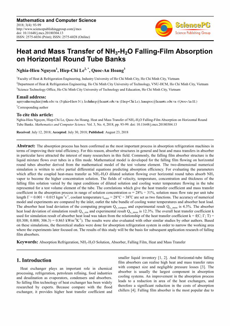
2.1. Model Description
A test volume element has 100% wetted ratio. 3D physical
models become 2D physical model has dilute solution flow
direction along the tube circumference by coordinate x. Film
thickness direction is from the tube center by coordinate y. Any
points on the film are determined by coordinate θ, y respectively.
Figure 1. 2D physical model.
Assumptions of 2D physical model
1. The flow is laminar and there are no interfacial waves;
2. Wettability of the solution on the tube surface is 100%;
3. Thermodynamic equilibrium exits at the interface
between of solution film and vapor;
4. Heat transfer from interface to vapor phase is negligible;
5. The variation of film thickness due to absorption of NH3
vapor is negligible;
6. Outside tube surface temperature equals the cooling
water temperature.
2.2. Mathematical Description
The continuity, momentum, energy, transport equations of
solution falling film on tube bundle are described 2D [10-13].
For a given solution mass flow rate per unit tube length
� � �� /� (kgm-1
s-1
). Film thickness (m) is expressed as
equation (1).
1/3
3. .1
(W ). . .sinR g
υδρ θ
Γ= −
(1)
Where υ is kinematic viscosity of solution (m2s
-1) and WR
is wetted ratio of the tube (%).
Velocity component u (ms-1
) along x direction is belong to
flow direction as equation (2).
2.sin(2. . )
2.
gu y y
θ δυ
= − (2)
Velocity component v (ms-1
) along y direction is normal to
flow direction as equation (3).
2 1sin ( ).cos
2. 3o
g d yv y
dx R
δ θ δ θυ
= − + −
(3)
The phenomenon of coupled heat and mass transfer in
steady state is discribed by energy transport equation (4)
and spicies transport equation (5).
2
2
T T Tu v
x y yα∂ ∂ ∂+ =
∂ ∂ ∂ (4)
2
2u v D
x y y
ω ω ω∂ ∂ ∂+ =∂ ∂ ∂
(5)
Where α and β are thermal diffusivity (m2s
-1) and mass
diffusivity (m2s
-1) of solution respectively, while T and ω are
corresponding temperature and concentration of solution at
the appropriate reference point.
Concentration and temperature boundary conditions at the
inlet (6).
0
inin
in
T Tx x
y ω ωδ == → =≤ ≤
(6)
Concentration and temperature boundary conditions at the
tube wall surface (7).
w
00
all
in out
T Tx x x
yy
ω=≤ ≤ → ∂ == ∂
(7)
Mathematics and Computer Science 2018; 3(4): 93-99 95
Concentration and temperature boundary conditions at the
liquid-vapor interface (8).
.
int
int int
.( )
(1 )
'. ( )
( , ) ( )
in out
ab f
D dm at y concentration
dy
x x x dTq m h k at y heat flow
y dy
T f p at y equivalent
ρ ω δω
δδ
ω δ
= = −
≤ ≤ → = = = =
= =
(8)
Where m’ is calculated mass flux (kgm-2
s-1
), hab is heat of
absorption (Jkg-1
) and kf is thermal conduction conductivity
of solution (Wm-1
K-1
).
Local heat transfer coefficients from interface to bulk
solution along the film flow (9) and from bulb solution to
tube wall surface along the film flow (10) in terms of Nusselt
number.
int
.
( )
ib
ib
f sb
dTNu at y
k T T dy
α δ δ δ= = =−
(9)
wall
wall
wall
.0
( )
b
b
f sb
dTNu at y
k T T dy
α δ δ= = =−
(10)
Where αib and αbwall are heat transfer coefficients from
interface to bulk and from bulk to wall (Wm-2
K-1
), while Tint,
Tsb and Twall are temperatures at interface, bulk solution, and
tube wall respectively.
Mass transfer coefficient from interface to bulk solution
along the film flow (11) in terms of Sherwood number.
int
'.
. .( )
m
ab ab sb
h mSh
D D
δρ ω ω
= =−
(11)
Where hm is mass transfer coefficient from interface to
bulk (ms-1
), Dab diffusion coeffiction of absorption (m2s
-1).
Total heat transfer coefficient from bulk solution to
cooling water (Wm-2
K-1
) can be expressed as (12).
w
w w
1 1 1 all
bwall allU
δα α λ
= + + (12)
Where αbwall and αw are convective heat transfer coefficients
from bulk solution to wall and for cooling water (Wm-2
K-1
),
while δwall and λwall are wall thickness of cooling tube (m) and
thermal conductivity of tube wall (Wm-1
K-1
) respectively.
The physical domain has a complex geometry. Moreover,
the film thicness is in micro-size vs half circumference length
of the cooling tube is 0.0157 m. This ratio make the domain
can not be meshed directly which must be transformed from
sliding coordinate xy to non-dimentional coordinate εη
making the computational domain rectangular.
3. Result and Discussion
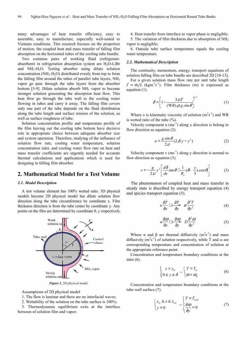
Parameters used in this study are presented in table 1. Figure
2 shows the mass transfer phenomenon as NH3 vapor is
absorbed in order to become a stronger concentration solution.
Table 1. Input parameters.
Parameters Values
Inlet temperature Tin 316 K
Inlet solution concentration �in 0.295
Absorber pressure p 2.8 bar
Solution density ρ 880 kgm-3
Dynamic viscosity µ 3.95* 10-4 Nsm-2
Solution flow rate Γ 0.008 kgm-1s-1
Out tube radius Ro 0.005 m
Thermal diffusivity α 6.7*10-8 m2s-1 Mass diffusivity D 4.4*10-9 m2s-1
Wall tube temperature Twall 303 K
Thermal conductivity of solution kf 0.384 Wm-1K-1
Figure 2. Concentration profile, ω.
Figure 2 is the three-dimensional distribution of the
concentration ω in the solution film domain. Concentration of
dilute solution when the solution has not contact the tube
assumed without absorption phenomenon so the concentration
equals the inlet concentration. Interface temperature is
saturated to solution concentration. At tube wall, solution
temperature equals wall temperature. When absorption
phenomenon occurs, concentration of the liquid-vapor
interface increases along ε-axis (x), then diffuses into the tube
wall along η-axis (y). This absorption generates heat making
liquid-vapor interface temperature increases along ε-axis (x).
Due to the temperature difference between the interface and
tube wall, heat transfer to the wall along axis η (y).
Average concentration of the film leaves the wall ω =
0.3537; increases 0.0587. Average temperature of the film
coming in the tube is 317.6 K (44.5°C), average temperature
of the film leaving tube is T = 304.8 K (31.7°C), decreases
12.8°C. Temperature of the liquid-vapor interface coming in
the tube is 332 K (58°C), temperature of the liquid-vapor
interface leaving the tube is T = 306.5 K (33.4°C), decreased
24.7°C. Difference temperature between liquid-vapor
interface leaving the tube and the tube wall is 3.4°C.
3.1. The Effect of Solution Flow Rate on Heat and Mass
Transfer
Input data as in table 1, tube wall temperature is 303 K,
average local temperature at the inlet of falling film on tube
is 325 K, solution flow rate Γ are changed: 0.001; 0.005;
96 Nghia-Hieu Nguyen et al.: Heat and Mass Transfer of NH3-H2O Falling-Film Absorption on Horizontal Round Tube Banks
0.008; 0.0113; 0.0146; 0.03 kgm-1
s-1
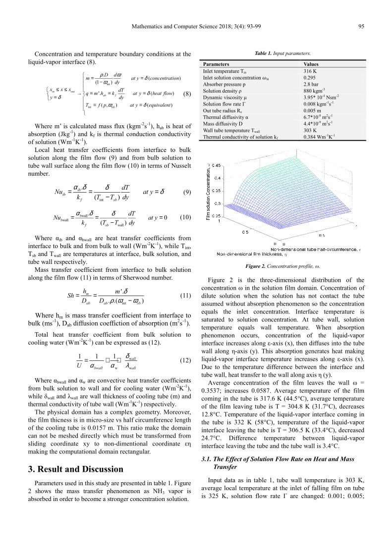
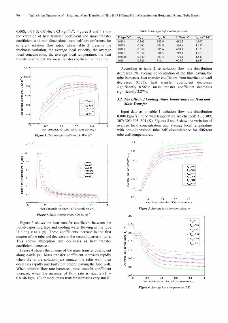
. Figures 3 and 4 show
the variation of heat transfer coefficient and mass transfer
coefficient with non-dimensional tube half circumference for
different solution flow rates, while table 2 presents the
thickness variation, the average local velocity, the average
local concentration, the average local temperature, the heat
transfer coefficient, the mass transfer coefficient of the film.
Figure 3. Heat transfer coefficient, U Wm-2K-1.
Figure 4. Mass transfer of the film, hm ms-1.
Figure 3 shows the heat transfer coefficient between the
liquid-vapor interface and cooling water flowing in the tube
U along ε-axis (x). These coefficients increase in the first
quarter of the tube and decrease in the second quarter of tube.
This shows absorption rate decreases as heat transfer
coefficient decreases.
Figure 4 shows the change of the mass transfer coefficient
along ε-axis (x). Mass transfer coefficient increases rapidly
when the dilute solution just contact the tube wall, then
decreases rapidly and fairly flat before leaving the tube wall.
When solution flow rate increases, mass transfer coefficient
increase, when the increase of flow rate is sizable (Γ =
0.0146 kgm-1
s-1
) or more, mass transfer increases very small.
Table 2. The effect of solution flow rate.
Γ kgm-1s-1 ωal_o Tal_o K U Wm-2K-1 hm ms-1 10-5
0.001 0.369 303.9 488.2 0.967
0.005 0.363 304.8 584.8 1.197
0.008 0.358 305.6 658.1 1.323
0.0113 0.354 306.5 719.1 1.467
0.0146 0.349 307.4 778.1 1.543
0.03 0.329 311.1 975.7 1.657
According to table 2, as solution flow rate distribution
decreases 1%, average concentration of the film leaving the
tube increases, heat transfer coefficient from interface to wall
decreases 0.72%, heat transfer coefficient decreases
significantly 0.56%; mass transfer coefficient decreases
significantly 3.27%.
3.2. The Effect of Cooling Water Temperature on Heat and
Mass Transfer
Input data as in table 1, solution flow rate distribution
0.008 kgm-1
s-1
, tube wall temperature are changed: 311; 309;
307; 305; 303; 301 (K). Figures 5 and 6 show the variation of
average local concentration and average local temperature
with non-dimensional tube half circumference for different
tube wall temperatures.
Figure 5. Average local concentration, ω.
Figure 6. Average local temperature, T K.
Mathematics and Computer Science 2018; 3(4): 93-99 97
When cooling water temperature decreases, average local
concentration increases (Figure 5), average local temperature
decreases (Figure 6).
Table 3. The effect of cooling water temperature.
Twall K ωal_o Tal_in/ Tal_o K U Wm-2K-1 hm ms-1 10-5
311 0.329 321/315 904 1.1688
309 0.332 320/313 926 1.2717
307 0.338 319/311 949 1.3713
305 0.344 318/309 969 1.4612
303 0.349 317/307 985 1.5398
301 0.355 316/305 900 1.6110
According to table 3, cooling water temperature decreases
1oC, average concentration of the film leaving the tube
increases, average film temperature leaving the tube
decreases, heat transfer coefficient increases 0.95%; mass
transfer coefficient increases significantly 3.7%.
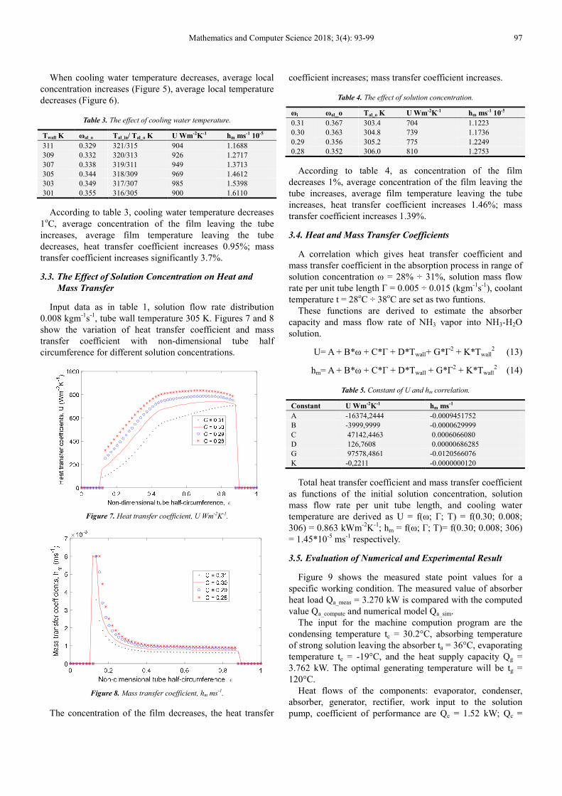
3.3. The Effect of Solution Concentration on Heat and
Mass Transfer
Input data as in table 1, solution flow rate distribution
0.008 kgm-1
s-1
, tube wall temperature 305 K. Figures 7 and 8
show the variation of heat transfer coefficient and mass
transfer coefficient with non-dimensional tube half
circumference for different solution concentrations.
Figure 7. Heat transfer coefficient, U Wm-2K-1.
Figure 8. Mass transfer coefficient, hm ms-1.
The concentration of the film decreases, the heat transfer
coefficient increases; mass transfer coefficient increases.
Table 4. The effect of solution concentration.
ωi ωal_o Tal_o K U Wm-2K-1 hm ms-1 10-5
0.31 0.367 303.4 704 1.1223
0.30 0.363 304.8 739 1.1736
0.29 0.356 305.2 775 1.2249
0.28 0.352 306.0 810 1.2753
According to table 4, as concentration of the film
decreases 1%, average concentration of the film leaving the
tube increases, average film temperature leaving the tube
increases, heat transfer coefficient increases 1.46%; mass
transfer coefficient increases 1.39%.
3.4. Heat and Mass Transfer Coefficients
A correlation which gives heat transfer coefficient and
mass transfer coefficient in the absorption process in range of
solution concentration ω = 28% ÷ 31%, solution mass flow
rate per unit tube length Γ = 0.005 ÷ 0.015 (kgm-1
s-1
), coolant
temperature t = 28oC ÷ 38
oC are set as two funtions.
These functions are derived to estimate the absorber
capacity and mass flow rate of NH3 vapor into NH3-H2O
solution.
U= A + B*ω + C*Г + D*Twall+ G*Г2 + K*Twall
2 (13)
hm= A + B*ω + C*Г + D*Twall + G*Г2 + K*Twall
2 (14)
Table 5. Constant of U and hm correlation.
Constant U Wm-2K-1 hm ms-1
A -16374,2444 -0.0009451752
B -3999,9999 -0.0000629999
C 47142,4463 0.0006066080
D 126,7608 0.00000686285
G 97578,4861 -0.0120566076
K -0,2211 -0.0000000120
Total heat transfer coefficient and mass transfer coefficient
as functions of the initial solution concentration, solution
mass flow rate per unit tube length, and cooling water
temperature are derived as U = f(ω; Г; T) = f(0.30; 0.008;
306) = 0.863 kWm-2
K-1
; hm = f(ω; Г; T)= f(0.30; 0.008; 306)
= 1.45*10-5
ms-1
respectively.
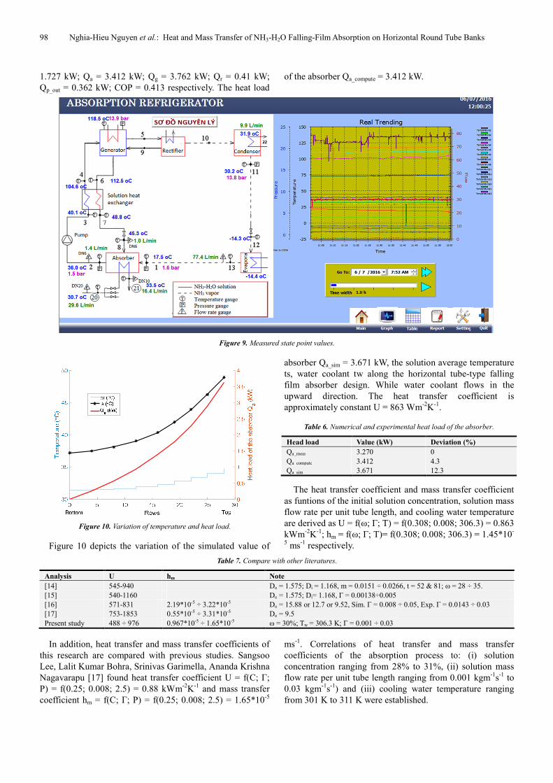
3.5. Evaluation of Numerical and Experimental Result
Figure 9 shows the measured state point values for a
specific working condition. The measured value of absorber
heat load Qa_meas = 3.270 kW is compared with the computed
value Qa_compute and numerical model Qa_sim.
The input for the machine compution program are the
condensing temperature tc = 30.2°C, absorbing temperature
of strong solution leaving the absorber ta = 36°C, evaporating
temperature te = -19°C, and the heat supply capacity Qg =
3.762 kW. The optimal generating temperature will be tg =
120°C.
Heat flows of the components: evaporator, condenser,
absorber, generator, rectifier, work input to the solution
pump, coefficient of performance are Qe = 1.52 kW; Qc =
98 Nghia-Hieu Nguyen et al.: Heat and Mass Transfer of NH3-H2O Falling-Film Absorption on Horizontal Round Tube Banks
1.727 kW; Qa = 3.412 kW; Qg = 3.762 kW; Qr = 0.41 kW;
Qp_out = 0.362 kW; COP = 0.413 respectively. The heat load
of the absorber Qa_compute = 3.412 kW.
Figure 9. Measured state point values.
Figure 10. Variation of temperature and heat load.
Figure 10 depicts the variation of the simulated value of
absorber Qa_sim = 3.671 kW, the solution average temperature
ts, water coolant tw along the horizontal tube-type falling
film absorber design. While water coolant flows in the
upward direction. The heat transfer coefficient is
approximately constant U = 863 Wm-2
K-1
.
Table 6. Numerical and experimental heat load of the absorber.
Head load Value (kW) Deviation (%)
Qa_meas 3.270 0
Qa_compute 3.412 4.3
Qa_sim 3.671 12.3
The heat transfer coefficient and mass transfer coefficient
as funtions of the initial solution concentration, solution mass
flow rate per unit tube length, and cooling water temperature
are derived as U = f(ω; Г; T) = f(0.308; 0.008; 306.3) = 0.863
kWm-2
K-1
; hm = f(ω; Г; T)= f(0.308; 0.008; 306.3) = 1.45*10-
5 ms
-1 respectively.
Table 7. Compare with other literatures.
Analysis U hm Note
[14] 545-940 Do = 1.575; Di = 1.168, m = 0.0151 ÷ 0.0266, t = 52 & 81; ω = 28 ÷ 35.
[15] 540-1160 Do = 1.575; Di= 1.168, Г = 0.00138÷0.005
[16] 571-831 2.19*10-5 ÷ 3.22*10-5 Do = 15.88 or 12.7 or 9.52, Sim. Г = 0.008 ÷ 0.05, Exp. Г = 0.0143 ÷ 0.03
[17] 753-1853 0.55*10-5 ÷ 3.31*10-5 Do = 9.5
Present study 488 ÷ 976 0.967*10-5 ÷ 1.65*10-5 ω = 30%; Tw = 306.3 K; Г = 0.001 ÷ 0.03
In addition, heat transfer and mass transfer coefficients of
this research are compared with previous studies. Sangsoo
Lee, Lalit Kumar Bohra, Srinivas Garimella, Ananda Krishna
Nagavarapu [17] found heat transfer coefficient U = f(C; Г;
P) = f(0.25; 0.008; 2.5) = 0.88 kWm-2
K-1
and mass transfer
coefficient hm = f(C; Г; P) = f(0.25; 0.008; 2.5) = 1.65*10-5
ms-1
. Correlations of heat transfer and mass transfer
coefficients of the absorption process to: (i) solution
concentration ranging from 28% to 31%, (ii) solution mass
flow rate per unit tube length ranging from 0.001 kgm-1
s-1
to
0.03 kgm-1
s-1
) and (iii) cooling water temperature ranging
from 301 K to 311 K were established.
Mathematics and Computer Science 2018; 3(4): 93-99 99
4. Conclusion
Solution flow rate increases, average local concentration of
the film decreases, average local temperature increases. Heat
transfer coefficient increases strongly, mass transfer
coefficient increases. When increasing of flow rate is sizable
Γ = 0.0146 kgm-1
s-1
or more, mass transfer increases very
small.
The effects of the solution concentration ω = 28% ÷ 31%,
solution mass flow rate per unit tube length Γ = 0.001 ÷
0.015 kgm-1
s-1
, cooling water temperature, and cooling water
tw = 28°C ÷ 38°C on the heat transfer coefficient U Wm-2
K-1
and mass transfer coefficient hm ms-1
of the absorption
process were:
a) As solution flow rate distribution decreases 1%, heat
transfer coefficient decreases significantly 0.56% and
mass transfer coefficient decreases significantly 3.27%.
b) As cooling water temperature decreases 1°C, heat
transfer coefficient increases 0.95%; mass transfer
coefficient increases significantly 3.7%.
c) As concentration of the film decreases 1%, heat transfer
coefficient increases 1.46%; mass transfer coefficient
increases 1.39%.
Two functions giving heat transfer coefficient and mass
transfer coefficient in the absorption process in range of
solution concentration ω = 28% ÷ 31%, solution mass flow
rate per unit tube length Γ = 0.001 ÷ 0.03 kgm-1
s-1
, coolant
temperature twater = 28°C ÷ 38°C are set as (13) and (14).
This research did not receive any specific grant from
funding agencies in the public, commercial, or not-for-profit
sectors.
References
[1] Jingdong Chena, Jili Zhanga, Zhijiang Hua, Zhixian Maa, “Falling Film Transitions on Horizontal Enhanced Tubes: Effect of Tube Spacing,” Procedia Engineering 205, 1542–1549 (2017).
[2] Christos N. Markides, Richard Mathie, Alexandros Charogiannis, “An experimental study of spatiotemporally resolved heat transfer in thin liquid-film flows falling over an inclined heated foil,” International Journal of Heat and Mass Transfer 93, 872–888 (2016).
[3] Niccolò Giannetti, Andrea Rocchetti, Seiichi Yamaguchi, Kiyoshi Saito, “Heat and mass transfer coefficients of falling-film absorption on a partially wetted horizontal tube,” Int. J. of Thermal Sciences 126, 56–66 (2018).
[4] María E._Alvarez, Jos_e A. Hern_andez, Mahmoud Bourouis, “Modelling the performance parameters of a horizontal falling film absorber with aqueous (lithium, potassium, sodium) nitrate solutionusing artificial neural networks,” Energy 102, 313-323 (2016).
[5] Xavier Daguenet-Fric, Paul Gantenbein, Jonas Müller,
“Benjamin Fumey, Robert Weber, Seasonal thermochemical energy storage: Comparison of the experimental results with the modelling of the falling film tube bundle heat and mass exchanger unit,” Renewable Energy 1-12 (2016).
[6] A. V. Bobylev, V. V. Guzanov, O. M. Heinz, S. M. Kharlamov, A. Z. Kvon, D. M. Markovich, “Characterization of 3-D wave flow regimes on falling liquid films,” International Journal of Multiphase Flow, Volume 99, Pages 474-484 (2018).
[7] Beethoven Narváez-Romo, Marx Chhay, Elí W. Zavaleta-Aguilar, José R. Simões-Moreira, “A Critical Review of Heat and Mass Transfer Correlations for LiBr-H2O and NH3-H2O Absorption Refrigeration Machines Using Falling Liquid Film Technology,” Applied Thermal Engineering, Volume 123, Pages 1079-1095 (2017).
[8] Delphine Triché, Sylvain Bonnot, Maxime Perier-Muzet, François Boudéhenn, Hélène Demasles, Nadia Caney, “Experimental and numerical study of a falling film absorber in an ammonia-water absorption chiller”, International Journal of Heat and Mass Transfer 111, 374–385 (2017).
[9] Qiang Zhang, Yide Gao, “Analytical solution of velocity for ammonia-water horizontal falling-film flow”, Applied Thermal Engineering, Volume 101, Pages 131-138 (2016).
[10] Niccolo Giannetti, Andrea Rocchetti, Kiyoshi Saito, Seiichi Yamaguchi, “Irreversibility analysis of falling film absorption over a cooled horizontal Tube,” International Journal of Heat and Mass Transfer 88, 755–765 (2015).
[11] V. D. Papaefthimiou, I. P. Koronaki, D. C. Karampinos, E. D. Rogdakis, “A novel approach for modelling LiBr- H2O falling film absorption on cooled horizontal bundle of tubes,” Int. J. of refrigeration 35, p. 1115-1122 (2012).
[12] L. Harikrishnan, Shaligram Tiwari, M. P. Maiya, “Numerical study of heat and mass transfer characteristics on a falling film horizontal tubular absorber for R-134a-DMAC,” International Journal of Thermal Sciences 50, p. 149-159 (2011).
[13] Conlisk AT, Mao J., “Nonisothermal absorption on a horizontal cylindrical tube-1. The film flow,” Chemical engineering science, 51, p. 1275-1285, 1996.
[14] Meacham, J. M. G., Srinivas, Ammonia-Water Absorption Heat and Mass Transfer in Microchannel Absorbers with Visual Confirmation, ASHRAE 2004. 110 (1): p. 525-532.
[15] Srinivas Garimella, Matthew D. Determan, J. MarkMeacham, Sangsoo Lee, Timothy C. Ernst, “Microchannel component technology for system-wide application in ammonia/water absorption heat pumps,” International Journal of Refrigeration, 34 (5): p. 1184-1196 (2011).
[16] Phan, T. T. (PhD. Thesis), Performance of Horizontal Tube Absorber with Variation of Tube Diameter, 2007, Pukyong National University [Thailand].
[17] Sangsoo Lee, Lalit Kumar Bohra, Srinivas Garimella, Ananda Krishna Nagavarapu, “Measurement of absorption rates in horizontal-tube falling-film ammonia-water absorbers,” International Journal of Refrigeration, 35 (3): p. 613-632 (2012).


![Presentation absorption 07-02-2014 [Mode de compatibilité]€¦ · absorption cooling system with falling film. ... Water dropplets elimination in a water vapor gas flow Identification](https://img.pdfslide.net/doc/110x75/5e22d6d8bad3dc224e14def0/presentation-absorption-07-02-2014-mode-de-compatibilit-absorption-cooling-system.jpg)