Embed Size (px)
Citation preview

Heat Loss & Gain Calculations
1
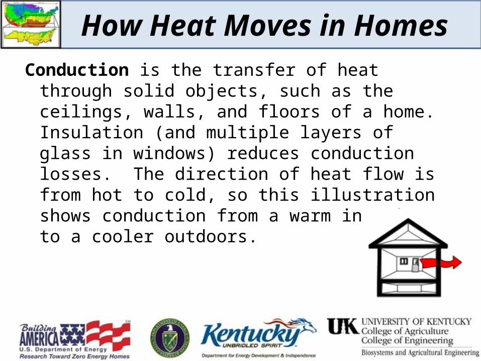
How Heat Moves in HomesConduction is the transfer of heat through solid
objects, such as the ceilings, walls, and floors of a home. Insulation (and multiple layers of glass in windows) reduces conduction losses. The direction of heat flow is from hot to cold, so this illustration shows conduction from a warm interior to a cooler outdoors.
2
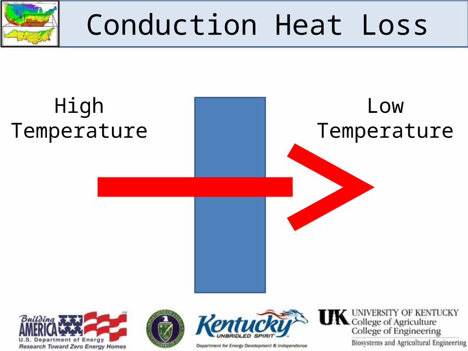
Conduction Heat Loss
HighTemperature
LowTemperature
3
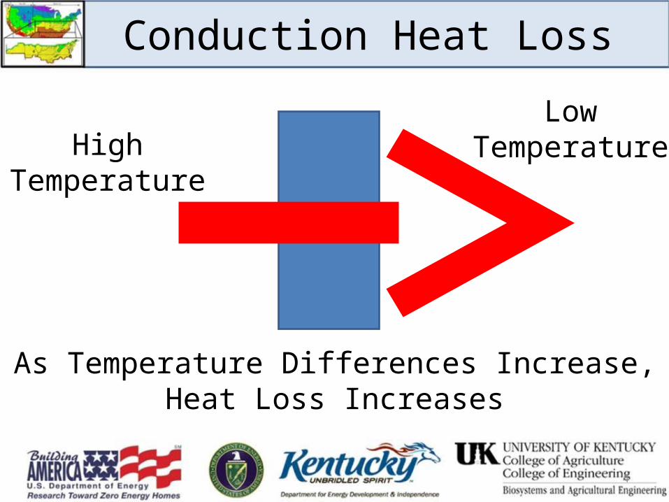
Conduction Heat Loss
HighTemperature
LowTemperature
As Temperature Differences Increase,Heat Loss Increases
4
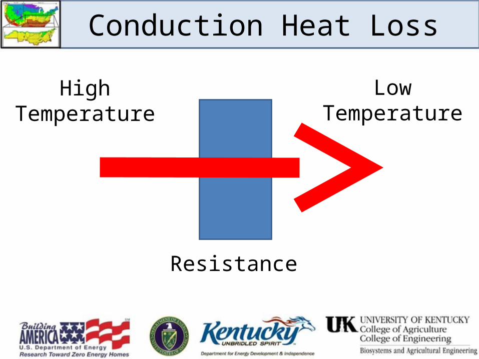
Conduction Heat Loss
HighTemperature
LowTemperature
Resistance
5
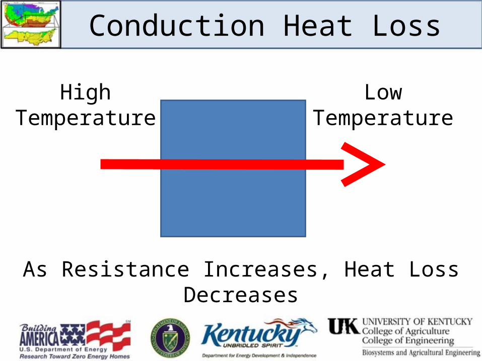
Conduction Heat Loss
HighTemperature
LowTemperature
As Resistance Increases, Heat Loss Decreases
6

7
Conduction Heat Loss
How Heat Moves in HomesConvection is the flow of heat by currents of air.
Air currents are caused by pressure differences, stirring fans, and air density changes as it heats and cools. As air becomes heated, it becomes less dense and rises; as air cools, it becomes more dense and sinks.
8
9
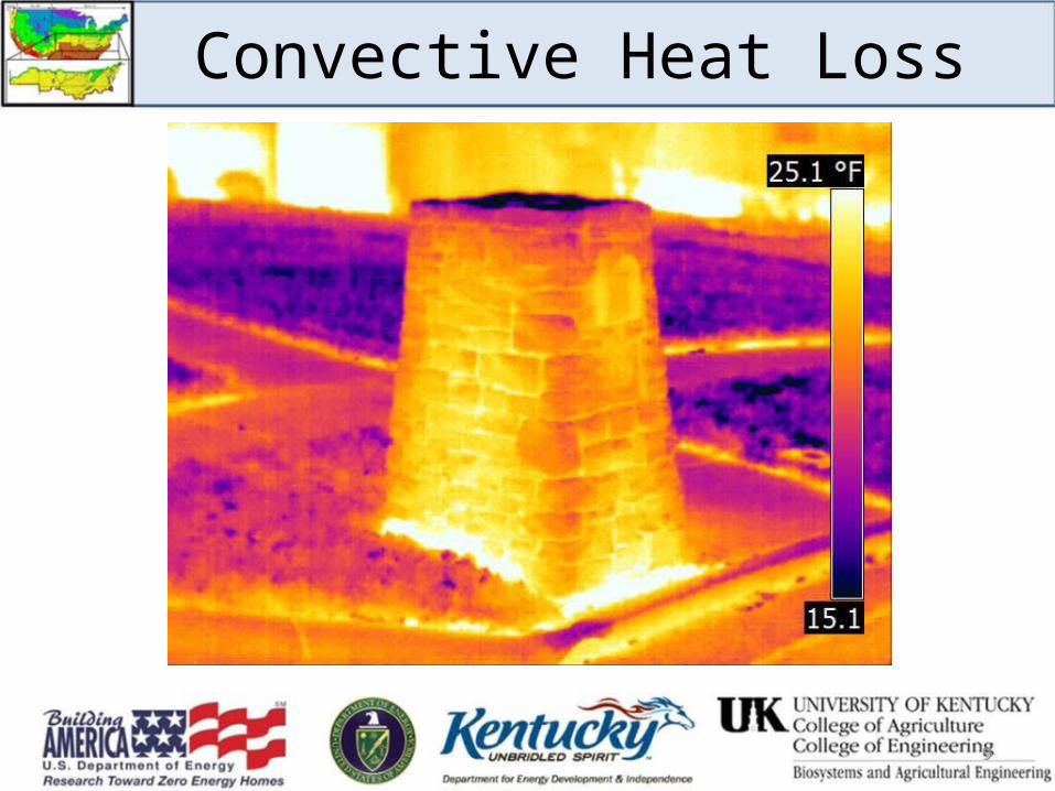
Convective Heat Loss
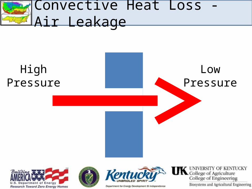
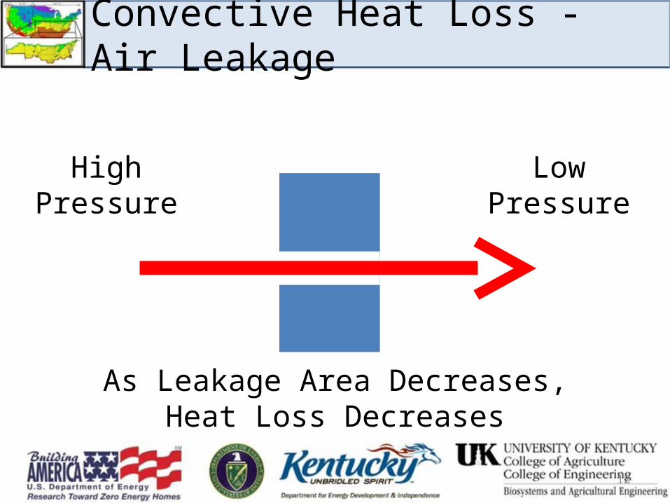
Convective Heat Loss - Air Leakage
HighPressure
LowPressure
10
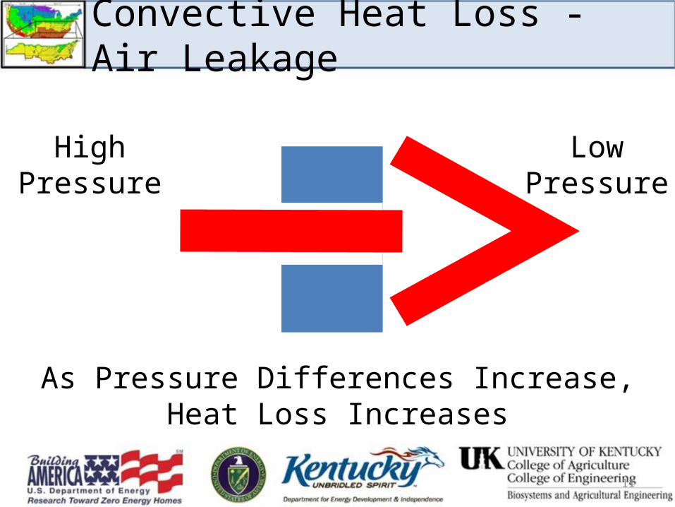
Convective Heat Loss - Air Leakage
HighPressure
LowPressure
As Pressure Differences Increase,Heat Loss Increases
11
HighPressure
LowPressure
As Leakage Area Decreases,Heat Loss Decreases
12
Convective Heat Loss - Air Leakage
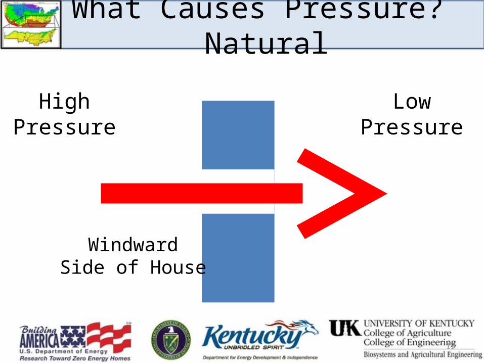
What Causes Pressure? Natural
HighPressure
LowPressure
13
WindwardSide of House
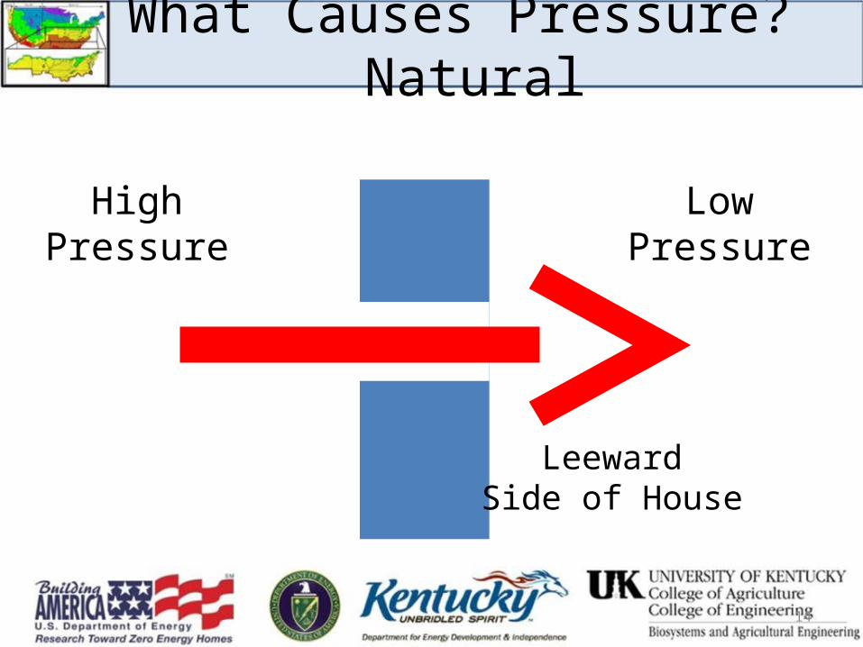
What Causes Pressure? Natural
HighPressure
LowPressure
14
LeewardSide of House

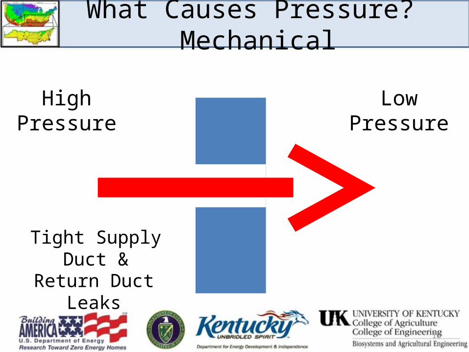
What Causes Pressure? Mechanical
HighPressure
LowPressure
15
Tight Supply Duct &
No Return Duct
What Causes Pressure? Mechanical
HighPressure
LowPressure
16
Tight Supply Duct &
Return Duct Leaks

What Causes Pressure? Mechanical
HighPressure
LowPressure
17
Supply Duct Leaks &
Tight Return Ducts
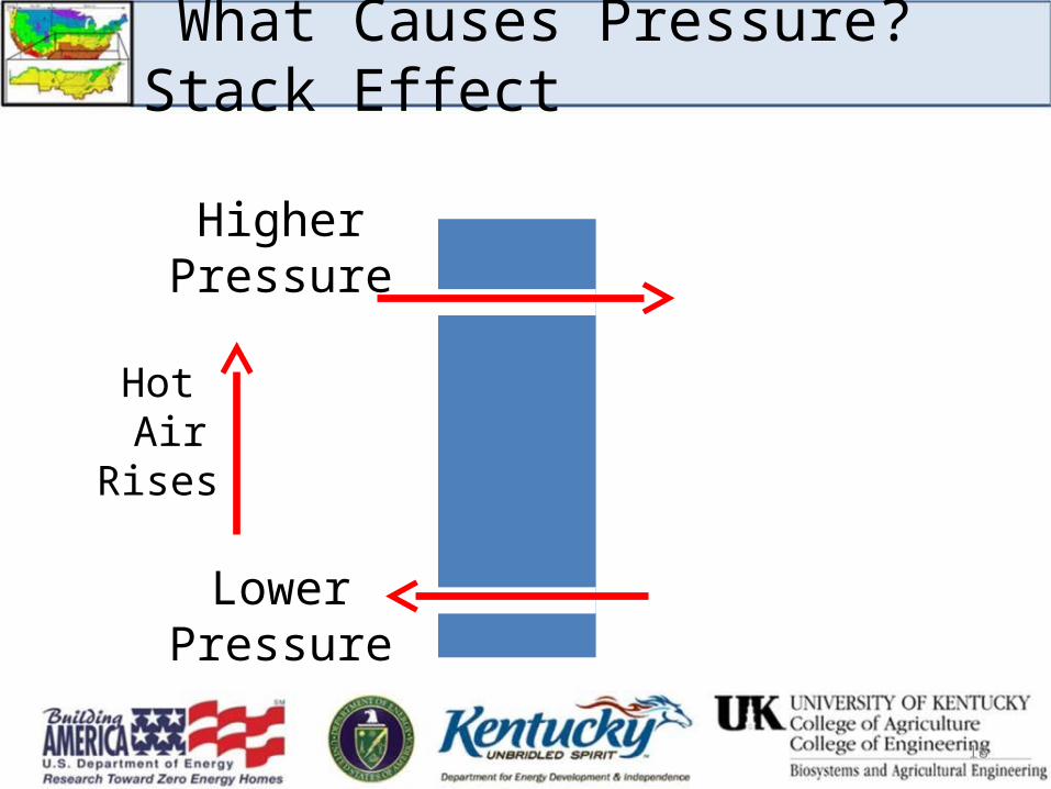
What Causes Pressure? Stack Effect
HigherPressure
LowerPressure
Hot Air
Rises
18
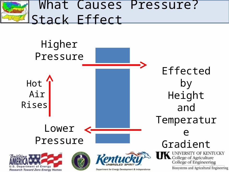
What Causes Pressure? Stack Effect
HigherPressure
LowerPressure
Hot Air
Rises
19
Effectedby
Heightand
TemperatureGradient
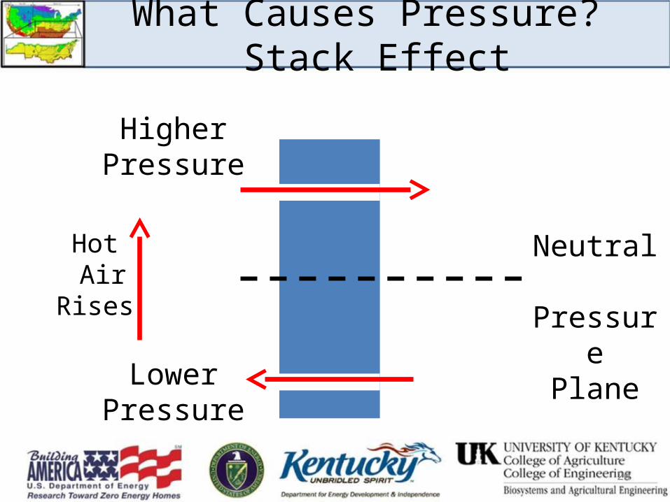
What Causes Pressure? Stack Effect
HigherPressure
LowerPressure
Hot Air
Rises
20
Neutral Pressure
Plane
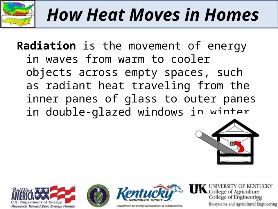
How Heat Moves in Homes
Radiation is the movement of energy in waves from warm to cooler objects across empty spaces, such as radiant heat traveling from the inner panes of glass to outer panes in double-glazed windows in winter.
21
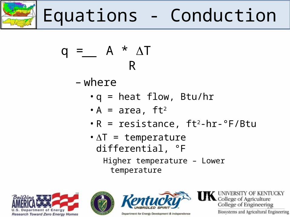
Equations - Conduction
q = A * T R
– where• q = heat flow, Btu/hr• A = area, ft2
• R = resistance, ft2-hr-°F/Btu• T = temperature differential, °F
Higher temperature – Lower temperature
22

Where Do You Get R?
• Table of R-values for various materials• Some values are for entire thickness
– Brick– Plywood– Gypsum Board
• Some values are per inch of thickness– Wood (framing)– Insulation
23
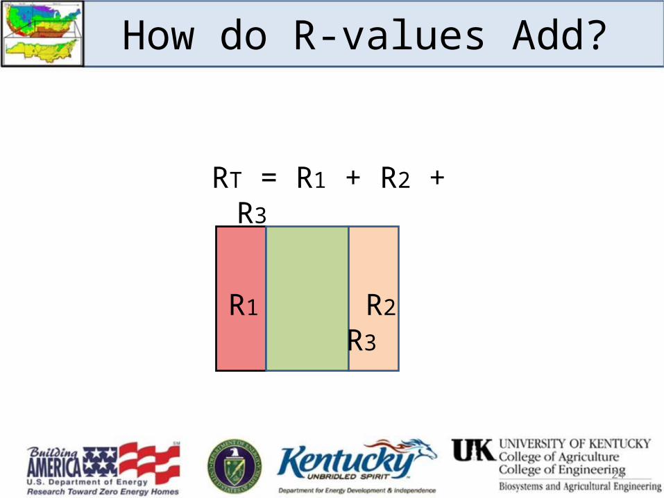
How do R-values Add?
24
RT = R1 + R2 + R3
R1 R2 R3
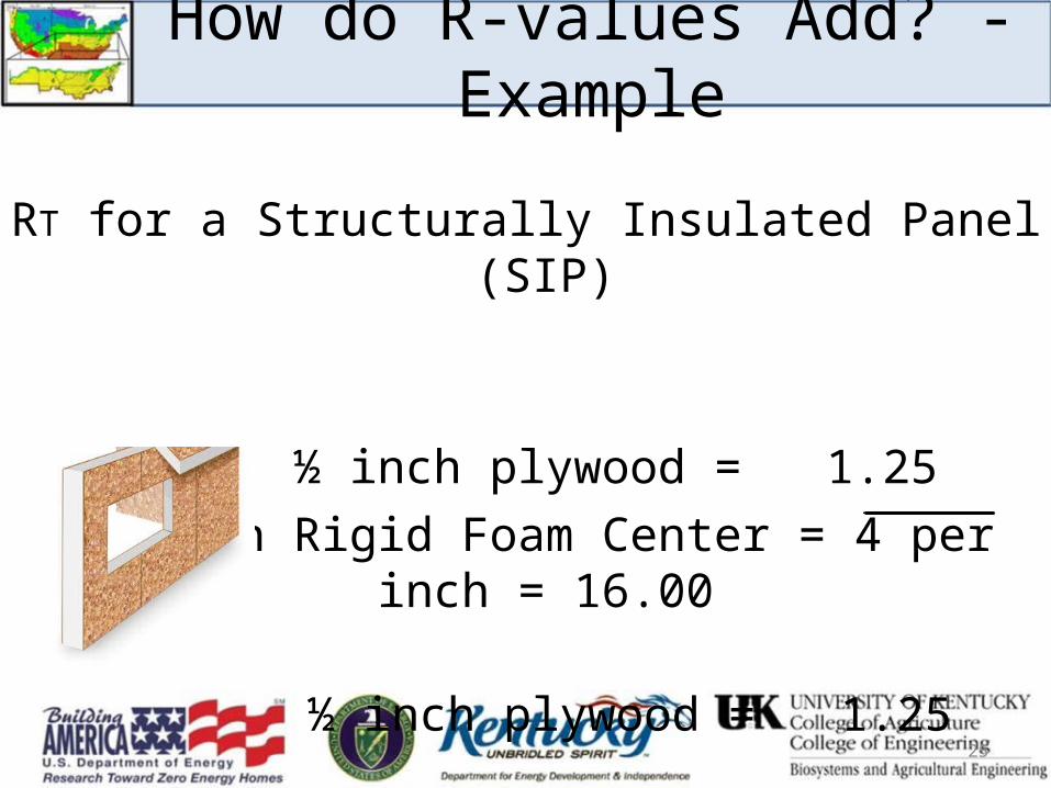
How do R-values Add? - Example
25
RT for a Structurally Insulated Panel (SIP)
½ inch plywood = 1.254 inch Rigid Foam Center = 4 per inch = 16.00
½ inch plywood = 1.25 RT = 18.50
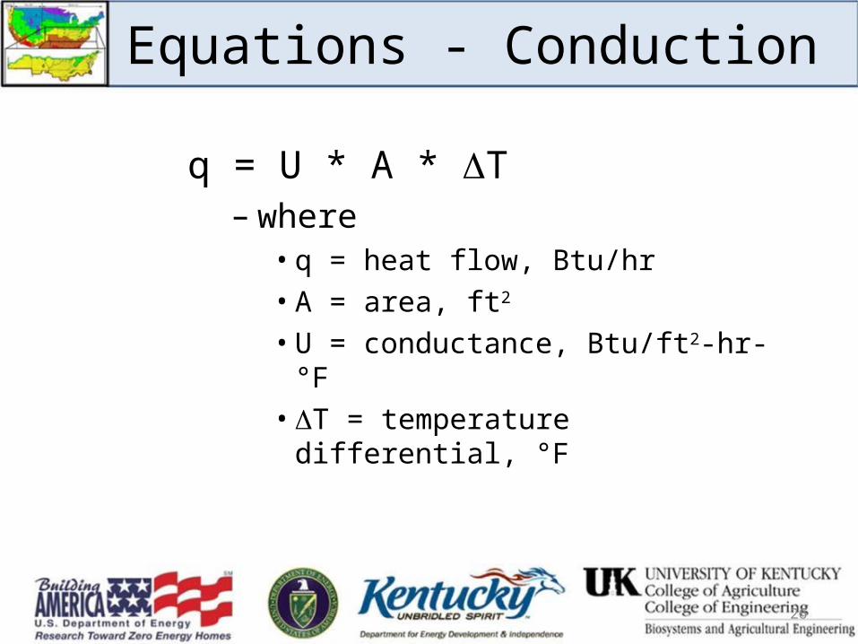
Equations - Conduction
q = U * A * T– where
• q = heat flow, Btu/hr• A = area, ft2
• U = conductance, Btu/ft2-hr-°F• T = temperature differential, °F
26
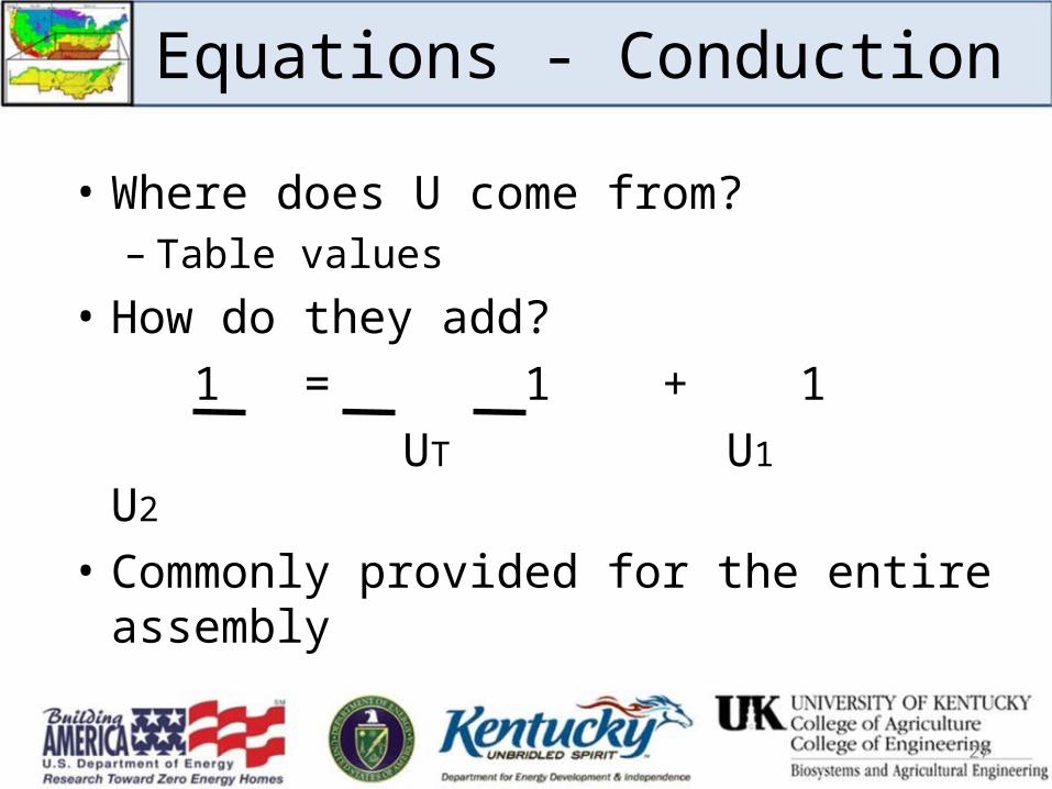
• Where does U come from?– Table values
• How do they add? 1 = 1 + 1
UT U1 U2 • Commonly provided for the entire assembly
27
Equations - Conduction
U-factor
A U-factor is used to describe an area that is composed of several materials.
Example:Window U-factor includes the glass, frame, and sash.
28

Relationship Between R and Uq = U * A * T
q = A* TR
U * A * T = A * T R
U * A * T = A * T R
U = 1 R
29
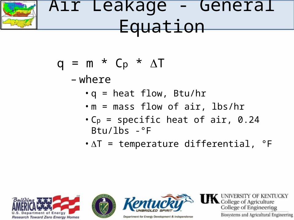
Air Leakage - General Equation
q = m * Cp * T– where
• q = heat flow, Btu/hr• m = mass flow of air, lbs/hr• Cp = specific heat of air, 0.24 Btu/lbs -°F• T = temperature differential, °F
30
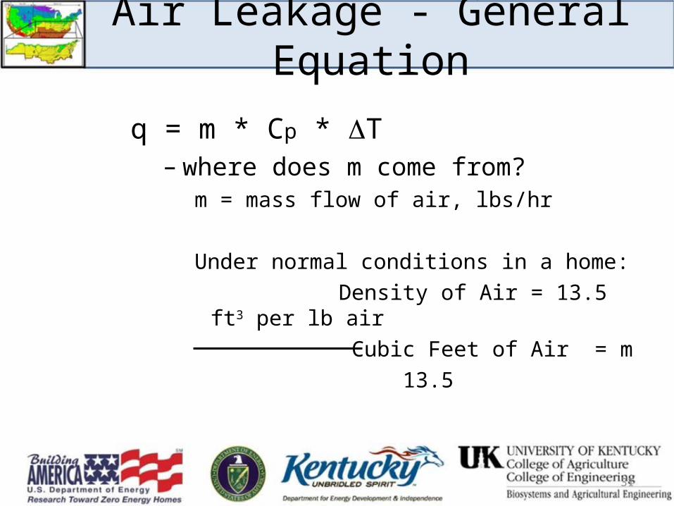
Air Leakage - General Equation
q = m * Cp * T– where does m come from?
m = mass flow of air, lbs/hr
Under normal conditions in a home: Density of Air = 13.5 ft3 per lb air Cubic Feet of Air = m 13.5
31
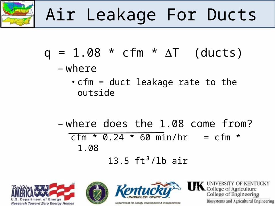
Air Leakage For Ducts
q = 1.08 * cfm * T (ducts)– where
• cfm = duct leakage rate to the outside
– where does the 1.08 come from?cfm * 0.24 * 60 min/hr = cfm * 1.08 13.5 ft³/lb air
32
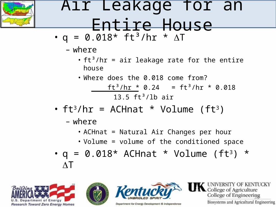
Air Leakage for an Entire House• q = 0.018* ft³/hr * T
– where• ft³/hr = air leakage rate for the entire house• Where does the 0.018 come from?
ft³/hr * 0.24 = ft³/hr * 0.018 13.5 ft³/lb air
• ft3/hr = ACHnat * Volume (ft3)– where
• ACHnat = Natural Air Changes per hour• Volume = volume of the conditioned space
• q = 0.018* ACHnat * Volume (ft3) * T
33
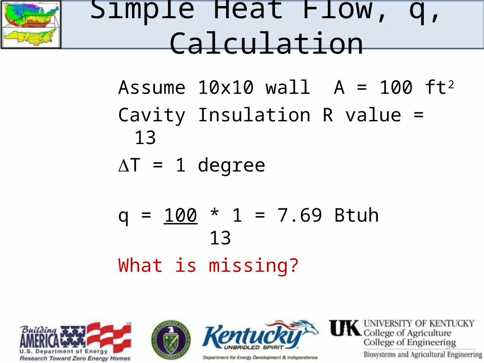
Simple Heat Flow, q, Calculation
Assume 10x10 wall A = 100 ft2
Cavity Insulation R value = 13T = 1 degree
q = 100 * 1 = 7.69 Btuh 13What is missing?
34
Simple Heat Flow, q, Calculation
What about the wood framing?
2x4 R-value = 4.38 (1.25 per inch)
35
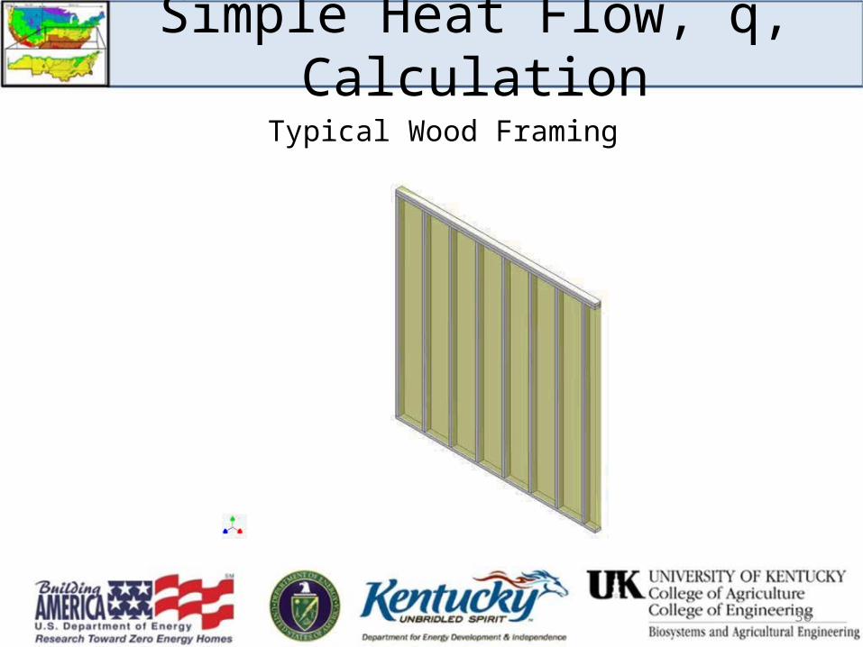
Simple Heat Flow, q, Calculation
Typical Wood Framing
36
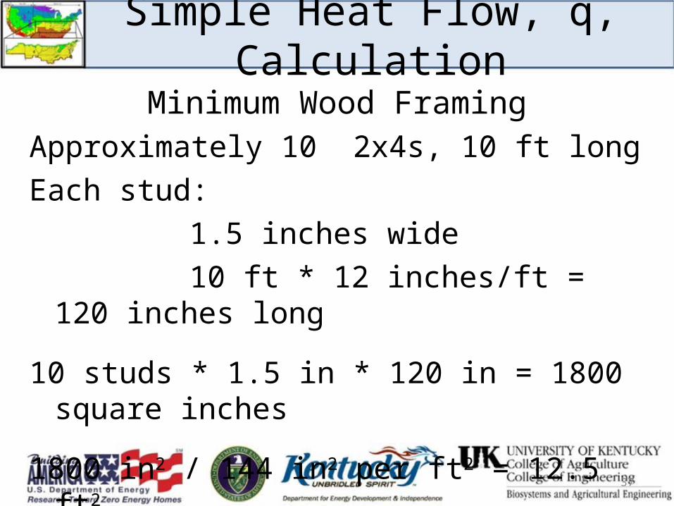
Minimum Wood FramingApproximately 10 2x4s, 10 ft longEach stud:
1.5 inches wide10 ft * 12 inches/ft = 120 inches long
10 studs * 1.5 in * 120 in = 1800 square inches
1800 in2 / 144 in2 per ft2 = 12.5 ft2
Simple Heat Flow, q, Calculation
37
Simple Heat Flow, q, Calculation w/Framing
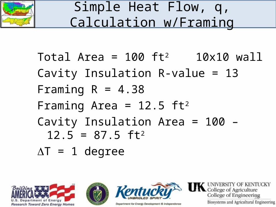
Total Area = 100 ft2 10x10 wallCavity Insulation R-value = 13Framing R = 4.38Framing Area = 12.5 ft2
Cavity Insulation Area = 100 – 12.5 = 87.5 ft2
T = 1 degree
38
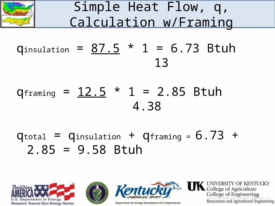
qinsulation = 87.5 * 1 = 6.73 Btuh 13
qframing = 12.5 * 1 = 2.85 Btuh 4.38
qtotal = qinsulation + qframing = 6.73 + 2.85 = 9.58 Btuh
39
Simple Heat Flow, q, Calculation w/Framing
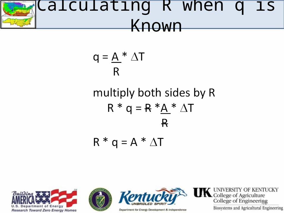
Calculating R when q is Known
40
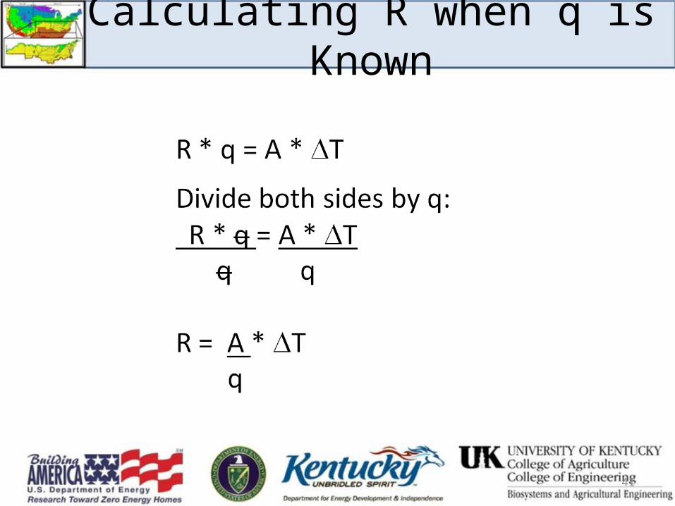
Calculating R when q is Known
41
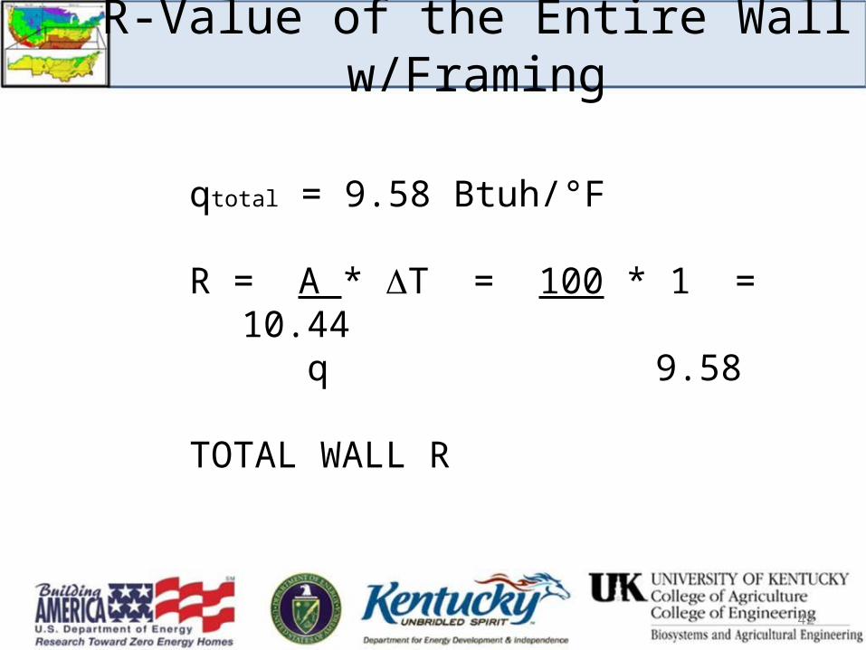
R-Value of the Entire Wall w/Framing
qtotal = 9.58 Btuh/°F
R = A * T = 100 * 1 = 10.44 q 9.58
TOTAL WALL R
42
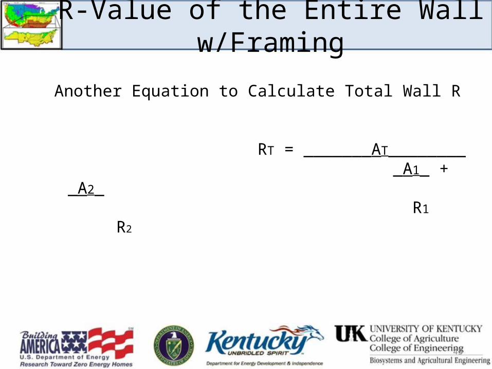
Another Equation to Calculate Total Wall R
RT = _______AT________ _A1_ + _A2_ R1 R2
43
R-Value of the Entire Wall w/Framing
Simple Heat Flow, q, Calculation
What if there is a window in the wall?
Window:Size 3 ft x 5 ft = 15 ft2 U-factor = 0.40
44
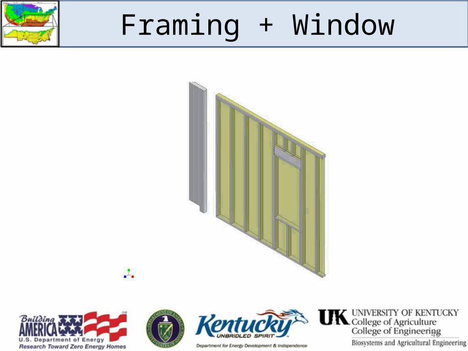
Framing + Window
45
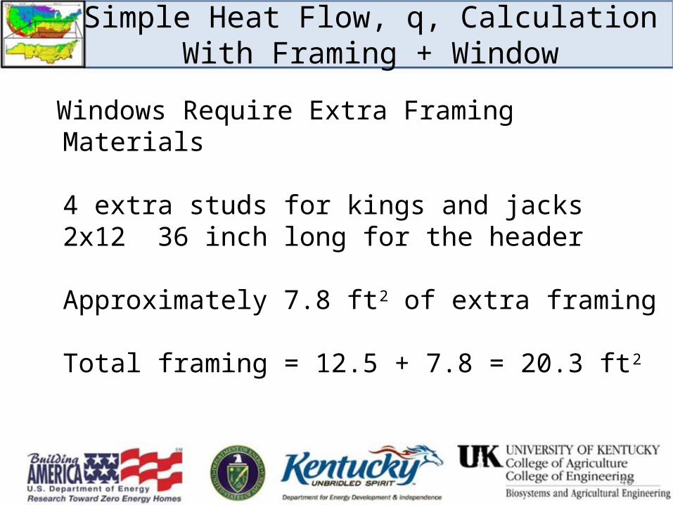
Simple Heat Flow, q, CalculationWith Framing + Window
Windows Require Extra Framing Materials
4 extra studs for kings and jacks2x12 36 inch long for the header
Approximately 7.8 ft2 of extra framing
Total framing = 12.5 + 7.8 = 20.3 ft2
46
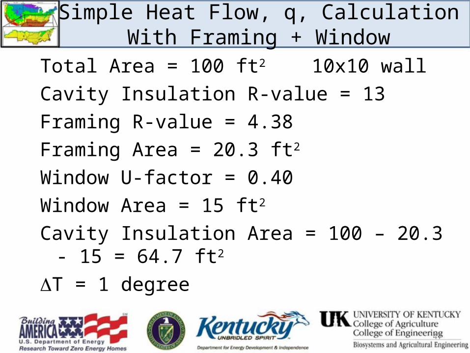
Simple Heat Flow, q, CalculationWith Framing + Window
Total Area = 100 ft2 10x10 wallCavity Insulation R-value = 13Framing R-value = 4.38Framing Area = 20.3 ft2
Window U-factor = 0.40Window Area = 15 ft2 Cavity Insulation Area = 100 – 20.3 - 15 = 64.7 ft2
T = 1 degree
47
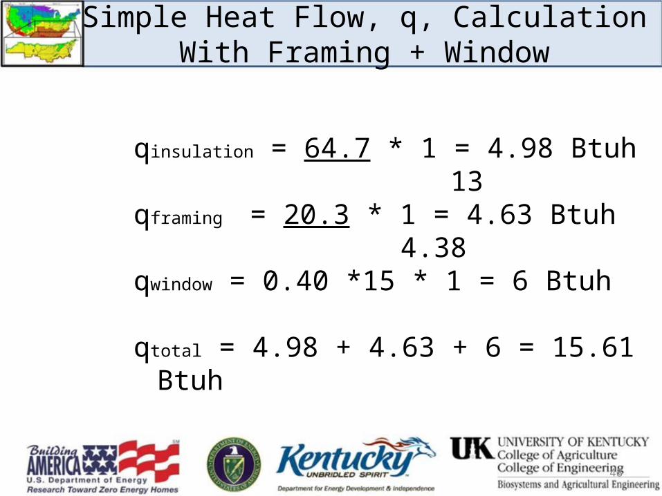
Simple Heat Flow, q, CalculationWith Framing + Window
qinsulation = 64.7 * 1 = 4.98 Btuh 13qframing = 20.3 * 1 = 4.63 Btuh 4.38qwindow = 0.40 *15 * 1 = 6 Btuh
qtotal = 4.98 + 4.63 + 6 = 15.61 Btuh
48
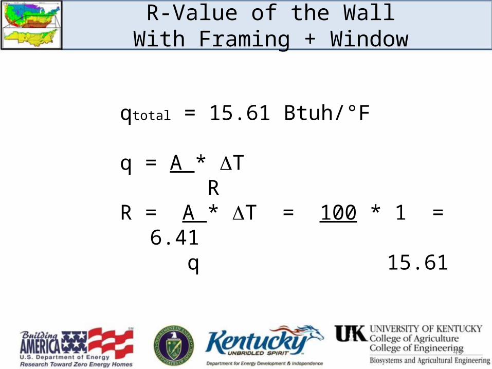
R-Value of the WallWith Framing + Window
qtotal = 15.61 Btuh/°F
q = A * T R R = A * T = 100 * 1 = 6.41
q 15.61
49
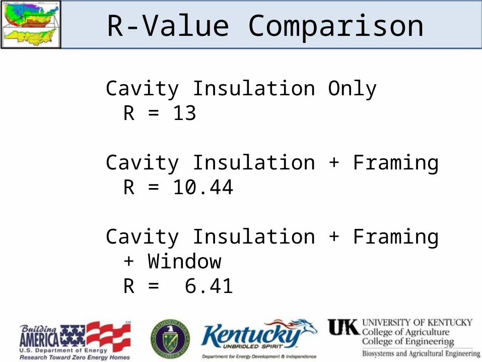
R-Value Comparison
Cavity Insulation OnlyR = 13
Cavity Insulation + FramingR = 10.44
Cavity Insulation + Framing + WindowR = 6.41
50
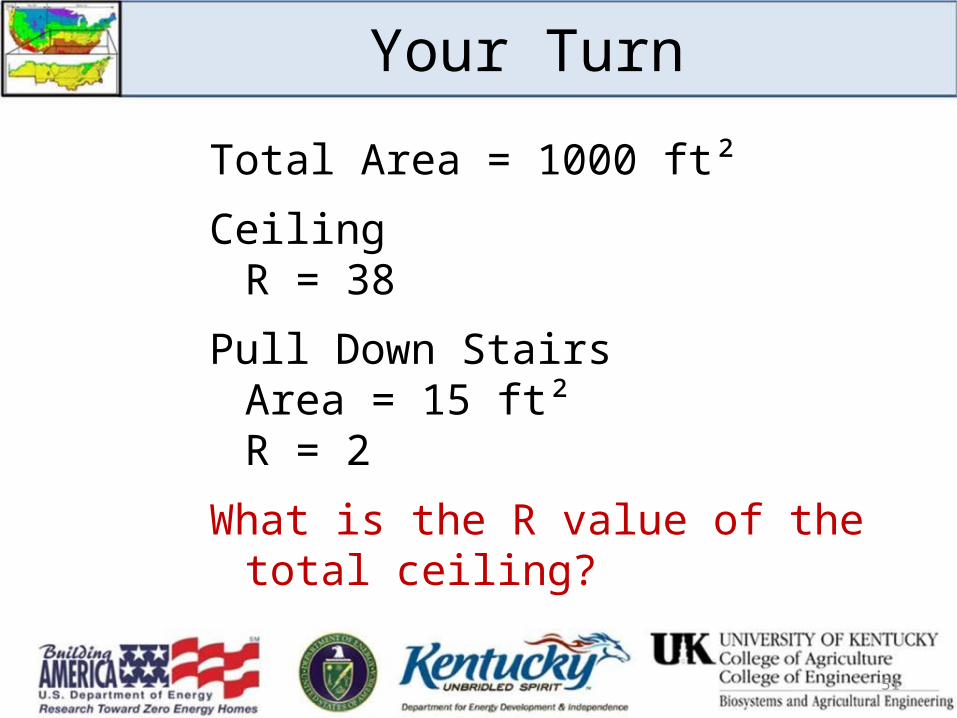
Your Turn
Total Area = 1000 ft²
CeilingR = 38
Pull Down StairsArea = 15 ft²R = 2
What is the R value of the total ceiling?
51
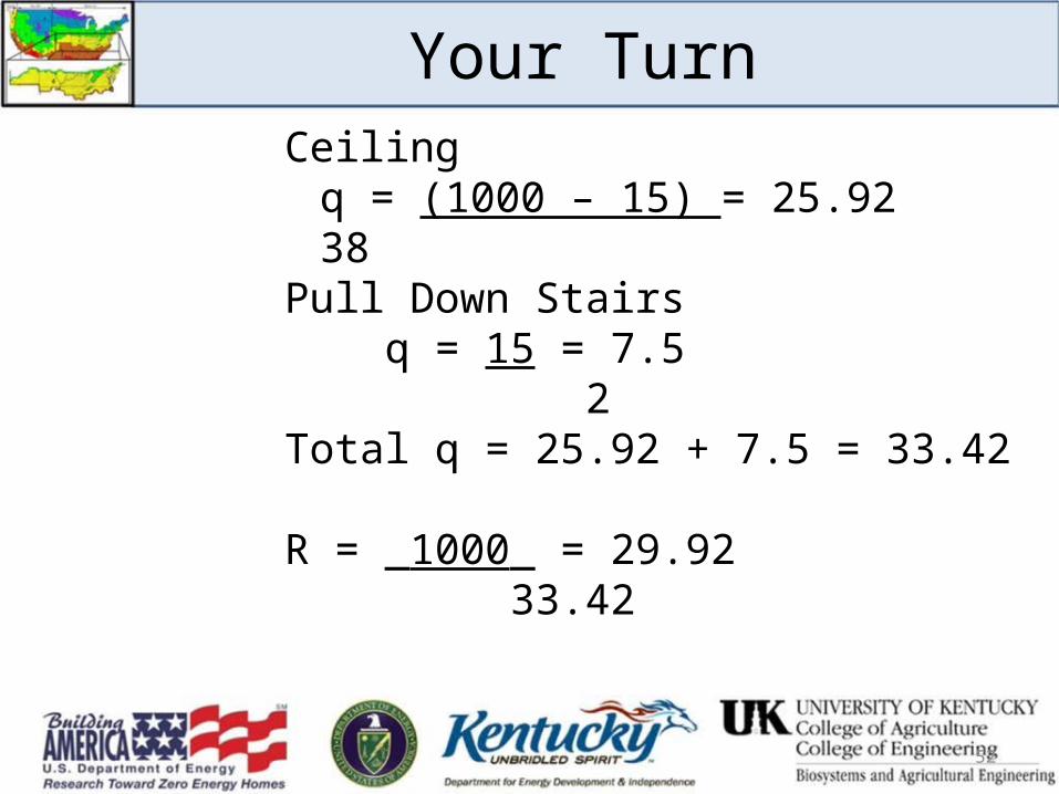
Your TurnCeiling
q = (1000 – 15) = 25.9238
Pull Down Stairs q = 15 = 7.5 2Total q = 25.92 + 7.5 = 33.42
R = _1000_ = 29.92 33.42
52
HERS Rating Software Examples
Must know:• Areas• R / U values• Temperature Differential
– Indirectly by knowing what is on the other side of the surface
53
54
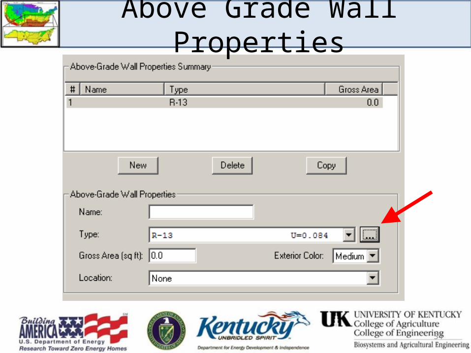
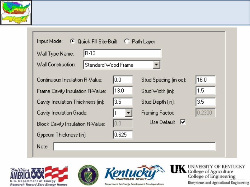
Above Grade Wall Properties
55
56
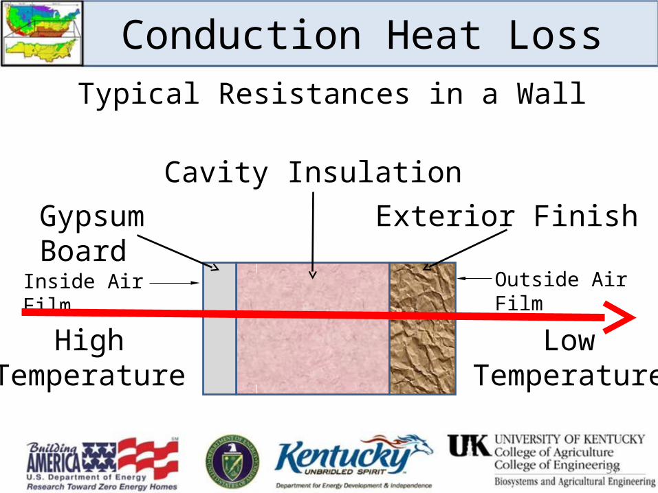
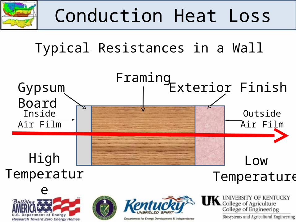
Conduction Heat Loss
HighTemperature
LowTemperature
Typical Resistances in a Wall
Outside Air Film
Exterior Finish
Cavity Insulation
Gypsum Board
Inside Air Film
57
58
59
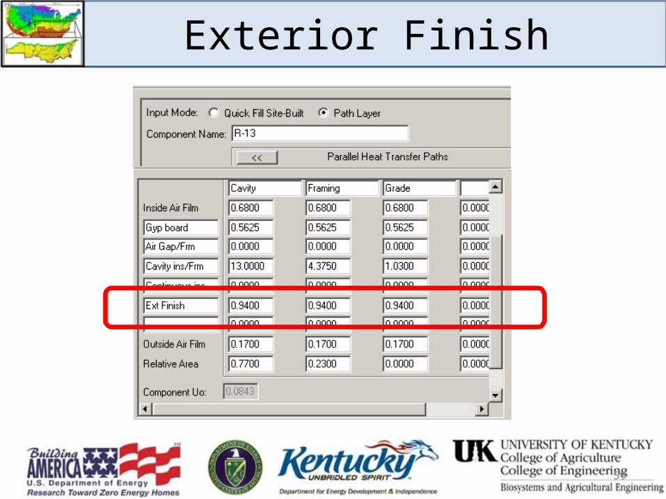
Exterior Finish
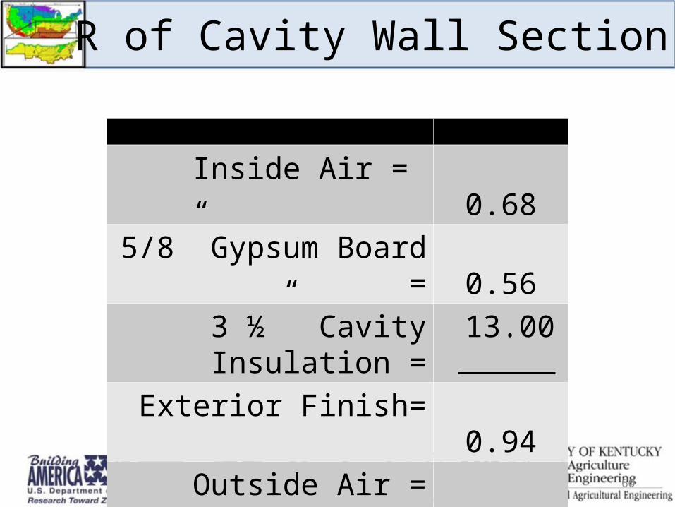
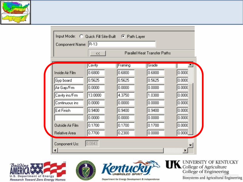
R of Cavity Wall Section
Inside Air = 0.685/8” Gypsum Board = 0.56
3 ½” Cavity Insulation = 13.00Exterior Finish= 0.94
Outside Air = 0.17Cavity Wall Section R = 15.35
60
Conduction Heat Loss
HighTemperature
LowTemperature
Typical Resistances in a Wall
Outside Air Film
Exterior FinishFraming
Gypsum Board
Inside Air Film
61
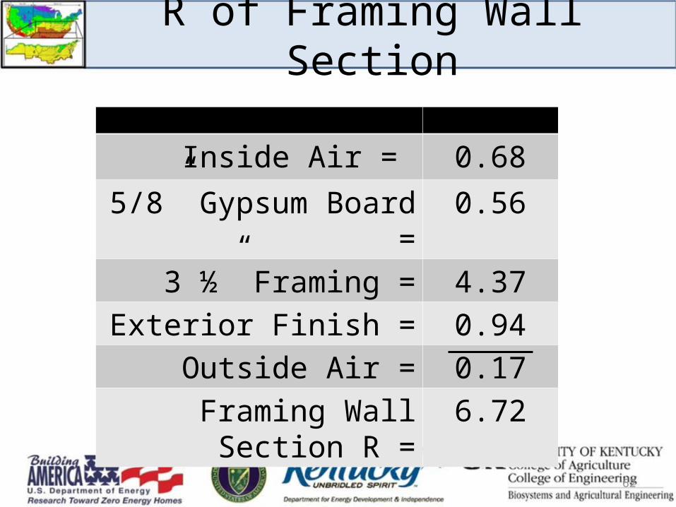
R of Framing Wall Section
Inside Air = 0.685/8” Gypsum Board = 0.56
3 ½” Framing = 4.37Exterior Finish = 0.94
Outside Air = 0.17Framing Wall Section R = 6.72
62
63
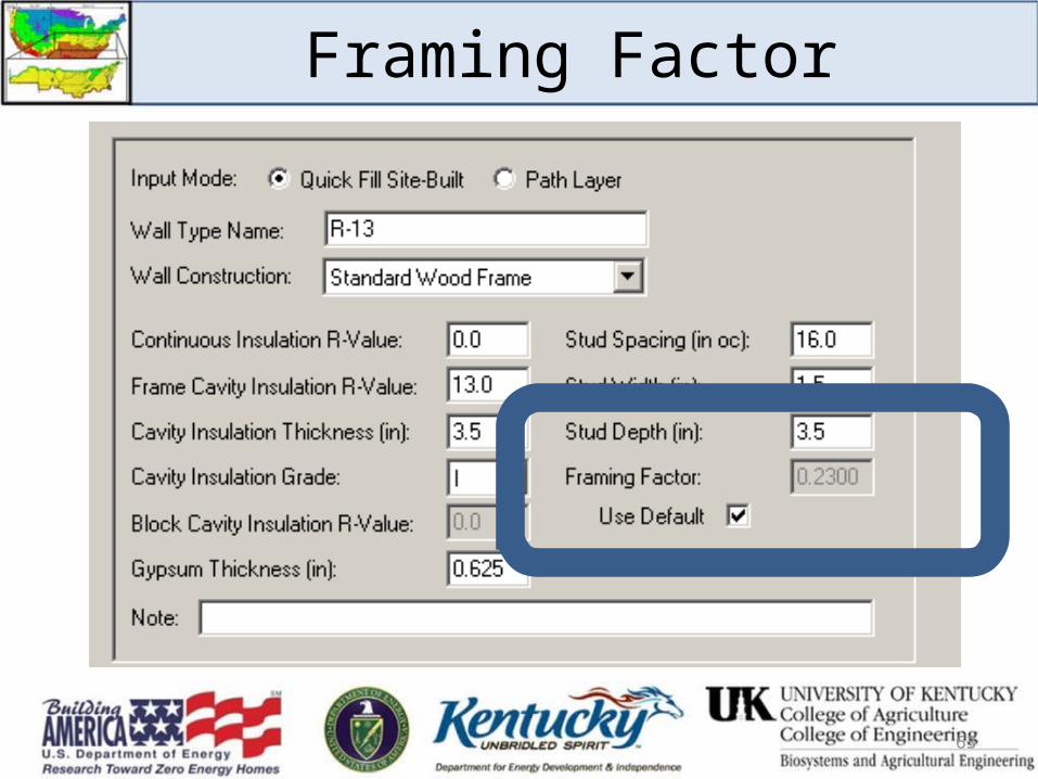
Framing Factor

64
Framing Factor
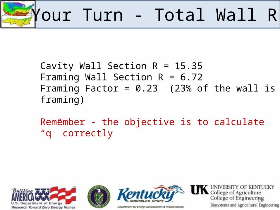
Your Turn - Total Wall R
Cavity Wall Section R = 15.35Framing Wall Section R = 6.72Framing Factor = 0.23 (23% of the wall is framing)
Remember - the objective is to calculate “q” correctly
65
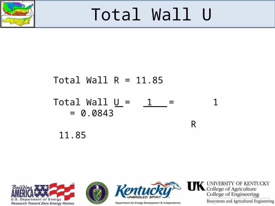
Total Wall U
Total Wall R = 11.85
Total Wall U = 1 = 1 = 0.0843 R 11.85
68
69
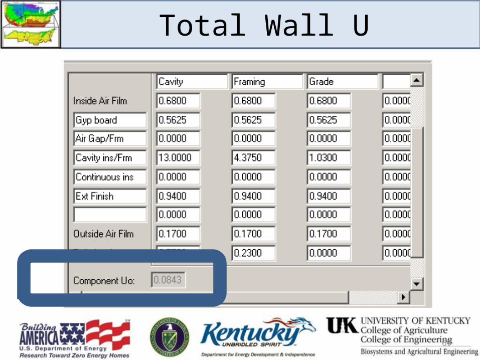
Total Wall U
Total UA for a House
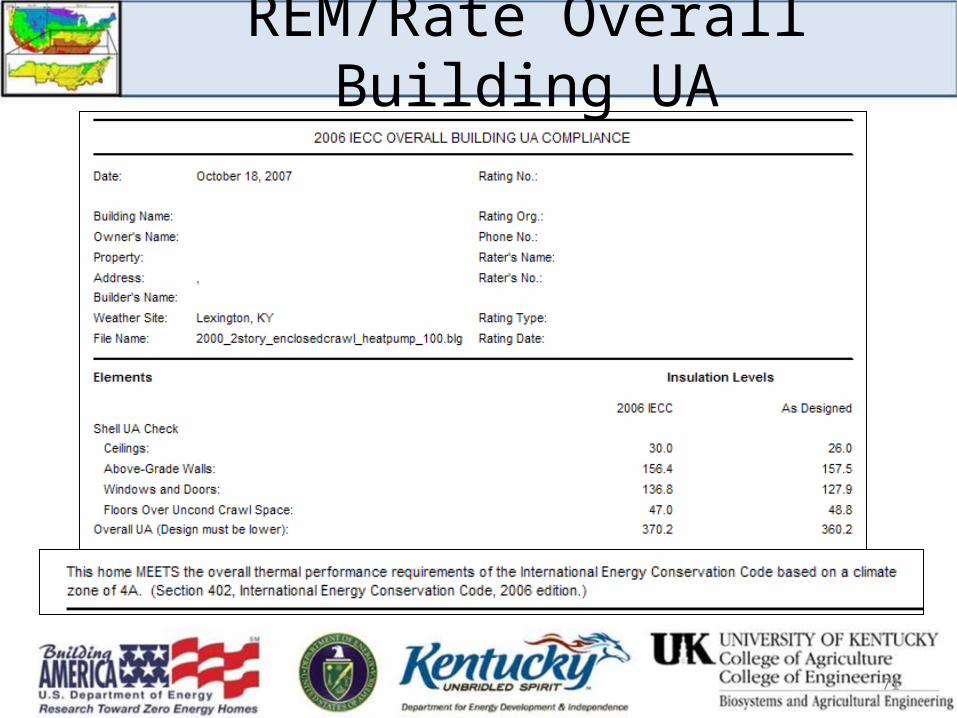
2006 IECC Compliance (2006 IRC, Chapter 11, Energy Efficiency)
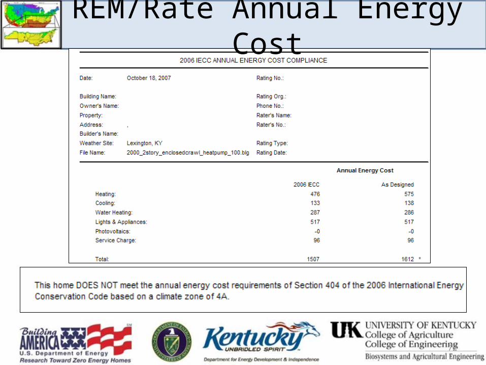
• Prescriptive• Overall Building UA• Annual Energy Cost
70
71
REM/Rate Overall Building UA
72
REM/Rate Annual Energy Cost
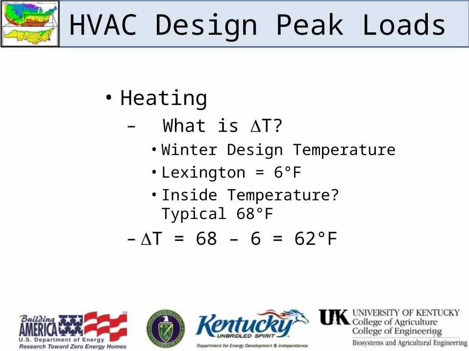
HVAC Design Peak Loads
• Heating– What is T?
• Winter Design Temperature• Lexington = 6°F • Inside Temperature? Typical 68°F
– T = 68 – 6 = 62°F
73
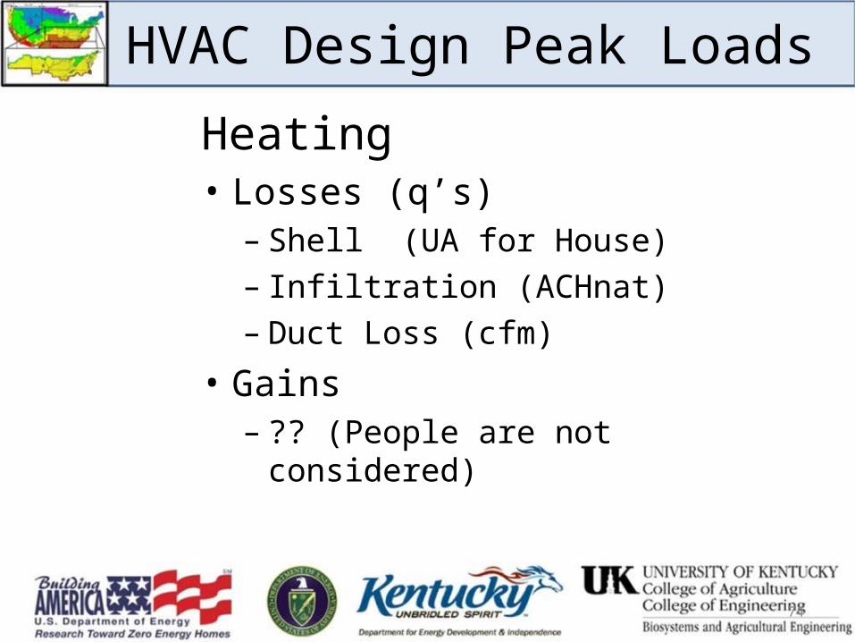
HVAC Design Peak Loads
Heating• Losses (q’s)
– Shell (UA for House)– Infiltration (ACHnat)– Duct Loss (cfm)
• Gains– ?? (People are not considered)
74
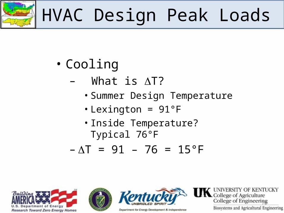
HVAC Design Peak Loads
• Cooling– What is T?
• Summer Design Temperature• Lexington = 91°F • Inside Temperature? Typical 76°F
– T = 91 – 76 = 15°F
75
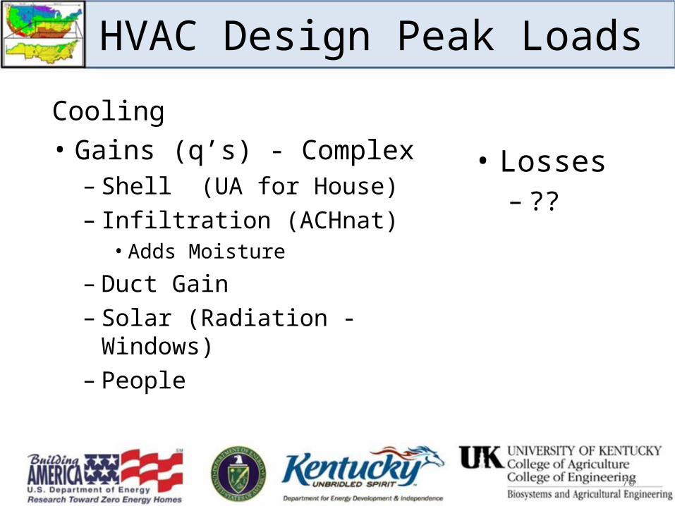
HVAC Design Peak Loads
Cooling• Gains (q’s) - Complex
– Shell (UA for House)– Infiltration (ACHnat)
• Adds Moisture
– Duct Gain– Solar (Radiation - Windows)– People
76
• Losses– ??

HVAC Design Peak Loads
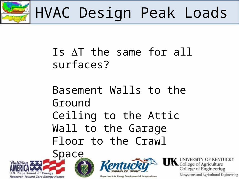
Is T the same for all surfaces?
77
HVAC Design Peak Loads
Is T the same for all surfaces?
Basement Walls to the GroundCeiling to the AtticWall to the GarageFloor to the Crawl Space
78
79
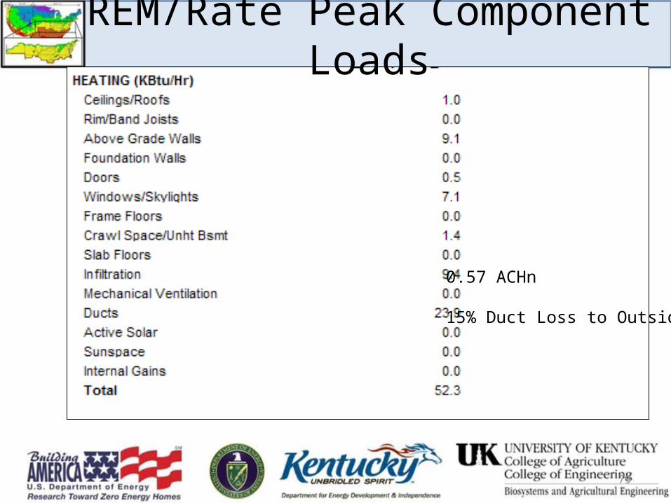
REM/Rate Peak Component Loads
0.57 ACHn
15% Duct Loss to Outside
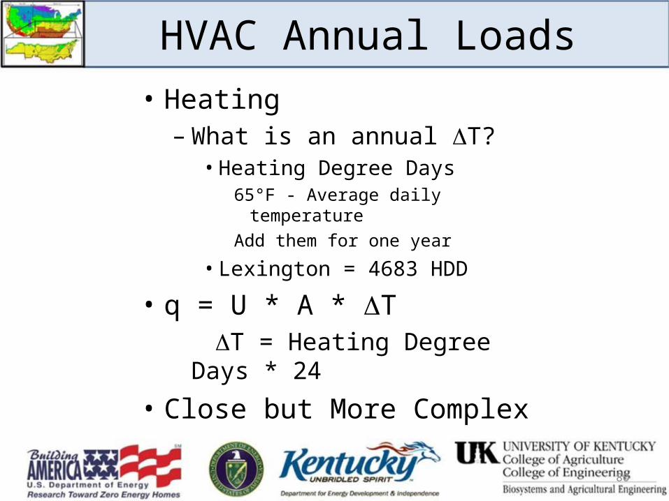
HVAC Annual Loads• Heating
– What is an annual T?• Heating Degree Days
65°F - Average daily temperature Add them for one year
• Lexington = 4683 HDD
• q = U * A * T T = Heating Degree Days * 24
• Close but More Complex
80
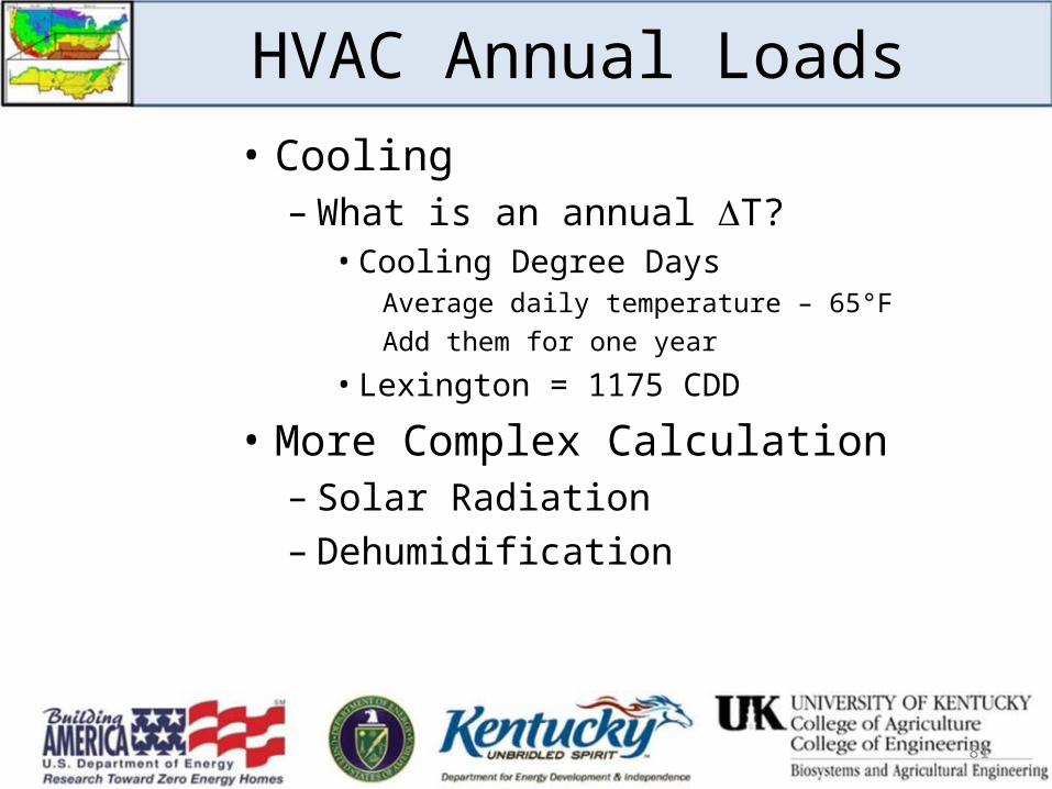
HVAC Annual Loads• Cooling
– What is an annual T?• Cooling Degree Days
Average daily temperature – 65°FAdd them for one year
• Lexington = 1175 CDD
• More Complex Calculation– Solar Radiation– Dehumidification
81
82
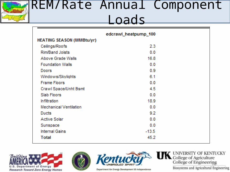
REM/Rate Annual Component Loads
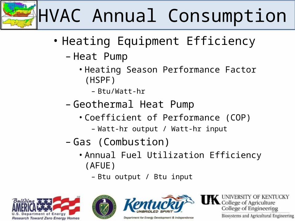
HVAC Annual Consumption• Heating Equipment Efficiency
– Heat Pump • Heating Season Performance Factor (HSPF)
– Btu/Watt-hr
– Geothermal Heat Pump• Coefficient of Performance (COP)
– Watt-hr output / Watt-hr input
– Gas (Combustion)• Annual Fuel Utilization Efficiency (AFUE)
– Btu output / Btu input
83
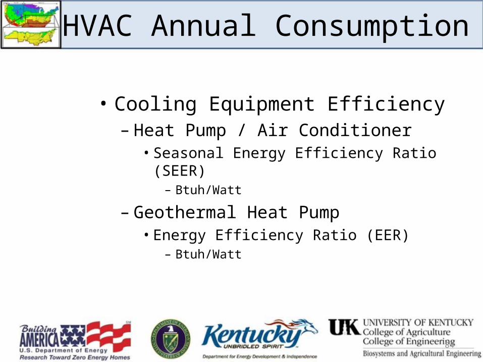
HVAC Annual Consumption
• Cooling Equipment Efficiency– Heat Pump / Air Conditioner
• Seasonal Energy Efficiency Ratio (SEER)– Btuh/Watt
– Geothermal Heat Pump• Energy Efficiency Ratio (EER)
– Btuh/Watt
84
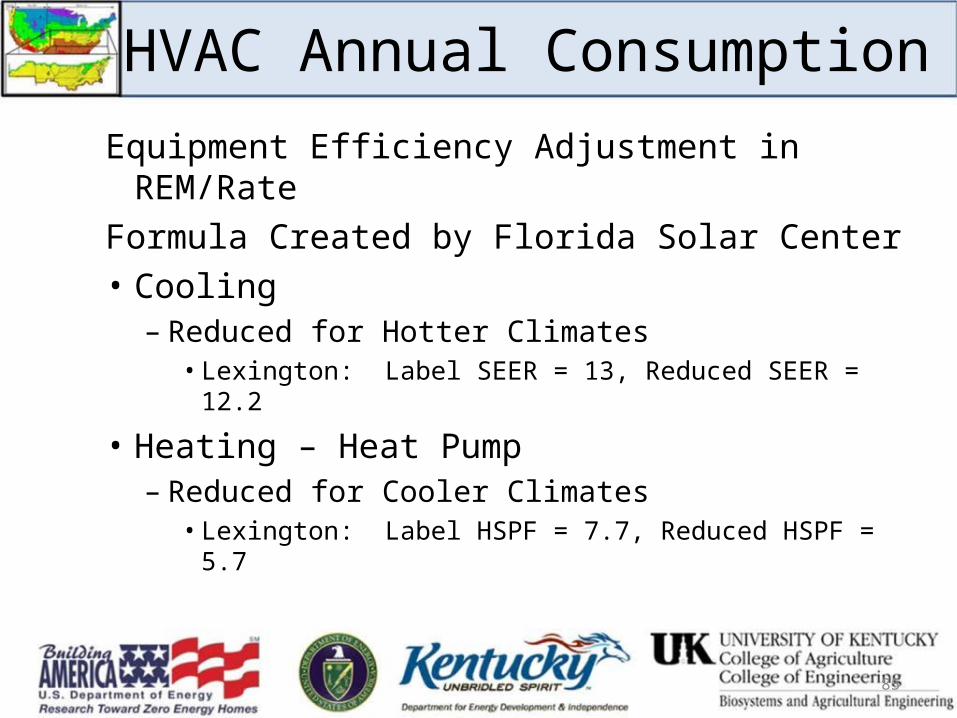
HVAC Annual Consumption
Equipment Efficiency Adjustment in REM/RateFormula Created by Florida Solar Center• Cooling
– Reduced for Hotter Climates• Lexington: Label SEER = 13, Reduced SEER = 12.2
• Heating – Heat Pump– Reduced for Cooler Climates
• Lexington: Label HSPF = 7.7, Reduced HSPF = 5.7
85
86
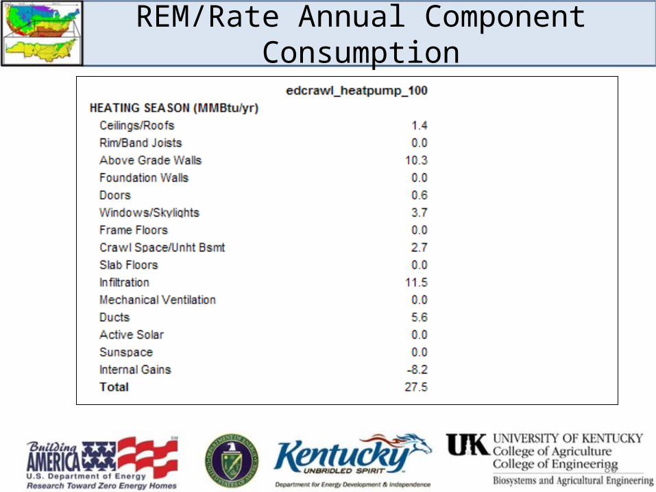
REM/Rate Annual Component Consumption