Embed Size (px)
Citation preview
1
- Do not store or use gasoline or other flam-mable vapors and liquids in the vicinity of thisor any other appliance.
- What to do if you smell gas
� Do not try to light any appliance.
� Do not touch any electrical switch.
� Do not use any phone in your building.
� Immediately call your gas supplier from aneighbor's phone. Follow the gas supplier'sinstructions.
� If you cannot reach your gas supplier, callthe fire department.
- Installation and service must be performed by aqualified installer, service agency, or the gassupplier.
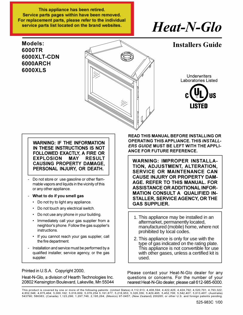
Heat-N-GloModels:6000TR6000XLT-CDN6000ARCH6000XLS
Installers Guide
WARNING: IMPROPER INSTALLA-TION, ADJUSTMENT, ALTERATION,SERVICE OR MAINTENANCE CANCAUSE INJURY OR PROPERTY DAM-AGE. REFER TO THIS MANUAL. FORASSISTANCE OR ADDITIONAL INFOR-MATION CONSULT A QUALIFIED IN-STALLER, SERVICE AGENCY, OR THEGAS SUPPLIER.
525-983C 1/00
READ THIS MANUAL BEFORE INSTALLING OROPERATING THIS APPLIANCE. THIS INSTALL-ERS GUIDE MUST BE LEFT WITH THE APPLI-ANCE FOR FUTURE REFERENCE.
1. This appliance may be installed in anaftermarket, permanently located,manufactured (mobile) home, where notprohibited by local codes.
2. This appliance is only for use with thetype of gas indicated on the rating plate.This appliance is not convertible for usewith other gases, unless a certified kit isused.
Please contact your Heat-N-Glo dealer for anyquestions or concerns. For the number of yournearest Heat-N-Glo dealer, please call 612-985-6000.
Printed in U.S.A. Copyright 2000,
Heat-N-Glo, a division of Hearth Technologies Inc.20802 Kensington Boulevard, Lakeville, Mn 55044
WARNING: IF THE INFORMATIONIN THESE INSTRUCTIONS IS NOTFOLLOWED EXACTLY, A FIRE OREXPLOSION MAY RESULTCAUSING PROPERTY DAMAGE,PERSONAL INJURY, OR DEATH.
UnderwritersLaboratories Listed
1This product is covered by one or more of the following patents: (United States) 4,112,913; 4,408,594; 4,422,426; 4,424,792; 4,520,791; 4,793,322;4,852,548; 4,875,464; 5,000,162; 5,016,609; 5,076,254 5,191,877; 5,218,953; 5,328,356; 5,429,495; 5,452,708; 5,542,407; 5,613,487; (Australia)543790; 586383; (Canada) 1,123,296; 1,297,746; 2,195,264; (Mexico) 97-0457; (New Zealand) 200265; or other U.S. and foreign patents pending.

2
!
!
!
!
!
!
!
!
!
!
!
!
!
!
!
!
!
!
SAFETY AND WARNING INFORMATION
READ and UNDERSTAND all instructions carefully before starting the installation.FAILURE TO FOLLOW these installation instructions may result in a possible firehazard and will void the warranty.
Prior to the first firing of the fireplace, READ the Using Your Fireplace section of theOwners Guide.
DO NOT USE this appliance if any part has been under water. Immediately CALL aqualified service technician to inspect the unit and to replace any part of the controlsystem and any gas control which has been under water.
THIS UNIT IS NOT FOR USE WITH SOLID FUEL.
Installation and repair should be PERFORMED by a qualified service person. Theappliance and venting system should be INSPECTED before initial use and at leastannually by a professional service person. More frequent cleaning may be required dueto excessive lint from carpeting, bedding material, etc. It is IMPERATIVE that the unit�scontrol compartment, burners, and circulating air passageways BE KEPT CLEAN toprovide for adequate combustion and ventilation air.
Always KEEP the appliance clear and free from combustible materials, gasoline, andother flammable vapors and liquids.
NEVER OBSTRUCT the flow of combustion and ventilation air. Keep the front of theappliance CLEAR of all obstacles and materials for servicing and proper operations.
Due to the high temperature, the appliance should be LOCATED out of traffic areasand away from furniture and draperies. Clothing or flammable material SHOULD NOTBE PLACED on or near the appliance.
Children and adults should be ALERTED to the hazards of high surface temperatureand should STAY AWAY to avoid burns or clothing ignition. Young children should beCAREFULLY SUPERVISED when they are in the same room as the appliance.
These units MUST use one of the vent systems described in the Installing the Fireplacesection of the Installers Guide. NO OTHER vent systems or components MAY BE USED.
This gas fireplace and vent assembly MUST be vented directly to the outside andMUST NEVER be attached to a chimney serving a separate solid fuel burningappliance. Each gas appliance MUST USE a separate vent system. Common ventsystems are PROHIBITED.
INSPECT the external vent cap on a regular basis to make sure that no debris isinterfering with the air flow.
The glass door assembly MUST be in place and sealed, and the trim door assemblyMUST be in place on the fireplace before the unit can be placed into safe operation.
DO NOT OPERATE this appliance with the glass door removed, cracked, or broken.Replacement of the glass door should be performed by a licensed or qualified serviceperson. DO NOT strike or slam the glass door.
The glass door assembly SHALL ONLY be replaced as a complete unit, as suppliedby the gas fireplace manufacturer. NO SUBSTITUTE material may be used.
DO NOT USE abrasive cleaners on the glass door assembly. DO NOT ATTEMPT toclean the glass door when it is hot.
Turn off the gas before servicing this appliance. It is recommended that a qualifiedservice technician perform an appliance check-up at the beginning of each heatingseason.
Any safety screen or guard removed for servicing must be replaced before operatingthis appliance.
3
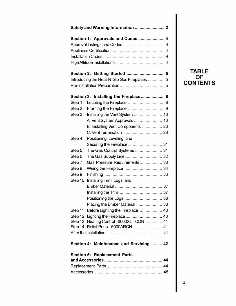
TABLEOF
CONTENTS
Safety and Warning Information ......................... 2
Section 1: Approvals and Codes ...................... 4Approval Listings and Codes ................................... 4
Appliance Certification ............................................. 4
Installation Codes .................................................... 4
High Altitude Installations.......................................... 4
Section 2: Getting Started ................................ 5Introducing the Heat-N-Glo Gas Fireplaces .............. 5
Pre-installation Preparation...................................... 5
Section 3: Installing the Fireplace .................... 8Step 1 Locating the Fireplace ............................... 8
Step 2 Framing the Fireplace ............................... 9
Step 3 Installing the Vent System ........................ 10
A. Vent System Approvals ........................ 10
B. Installing Vent Components ................. 20
C. Vent Termination ................................. 26
Step 4 Positioning, Leveling, and
Securing the Fireplace ............................. 31
Step 5 The Gas Control Systems ....................... 31
Step 6 The Gas Supply Line ............................... 32
Step 7 Gas Pressure Requirements ................... 33
Step 8 Wiring the Fireplace ................................ 34
Step 9 Finishing ................................................. 36
Step 10 Installing Trim, Logs, and
Ember Material ........................................ 37
Installing the Trim..................................... 37
Positioning the Logs ................................ 38
Placing the Ember Material ...................... 38
Step 11 Before Lighting the Fireplace.................... 40
Step 12 Lighting the Fireplace ............................... 40Step 13 Heating Control - 6000XLT-CDN .............. 41Step 14 Relief Ports - 6000ARCH ......................... 41
After the Installation ............................................... 41
Section 4: Maintenance and Servicing .......... 42
Section 5: Replacement Partsand Accessories ................................................. 44Replacement Parts ............................................... 44
Accessories ......................................................... 48
4
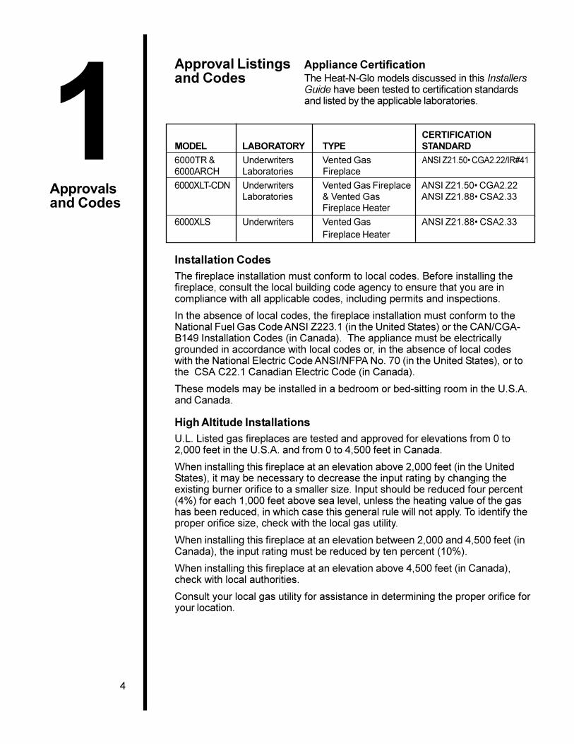
Approval Listingsand Codes
Appliance CertificationThe Heat-N-Glo models discussed in this InstallersGuide have been tested to certification standardsand listed by the applicable laboratories.
CERTIFICATIONMODEL LABORATORY TYPE STANDARD
6000TR & Underwriters Vented Gas ANSI Z21.50� CGA2.22/IR#416000ARCH Laboratories Fireplace
6000XLT-CDN Underwriters Vented Gas Fireplace ANSI Z21.50� CGA2.22Laboratories & Vented Gas ANSI Z21.88� CSA2.33
Fireplace Heater
6000XLS Underwriters Vented Gas ANSI Z21.88� CSA2.33Fireplace Heater
Installation CodesThe fireplace installation must conform to local codes. Before installing thefireplace, consult the local building code agency to ensure that you are incompliance with all applicable codes, including permits and inspections.
In the absence of local codes, the fireplace installation must conform to theNational Fuel Gas Code ANSI Z223.1 (in the United States) or the CAN/CGA-B149 Installation Codes (in Canada). The appliance must be electricallygrounded in accordance with local codes or, in the absence of local codeswith the National Electric Code ANSI/NFPA No. 70 (in the United States), or tothe CSA C22.1 Canadian Electric Code (in Canada).
These models may be installed in a bedroom or bed-sitting room in the U.S.A.and Canada.
High Altitude InstallationsU.L. Listed gas fireplaces are tested and approved for elevations from 0 to2,000 feet in the U.S.A. and from 0 to 4,500 feet in Canada.
When installing this fireplace at an elevation above 2,000 feet (in the UnitedStates), it may be necessary to decrease the input rating by changing theexisting burner orifice to a smaller size. Input should be reduced four percent(4%) for each 1,000 feet above sea level, unless the heating value of the gashas been reduced, in which case this general rule will not apply. To identify theproper orifice size, check with the local gas utility.
When installing this fireplace at an elevation between 2,000 and 4,500 feet (inCanada), the input rating must be reduced by ten percent (10%).
When installing this fireplace at an elevation above 4,500 feet (in Canada),check with local authorities.
Consult your local gas utility for assistance in determining the proper orifice foryour location.
1Approvalsand Codes
5
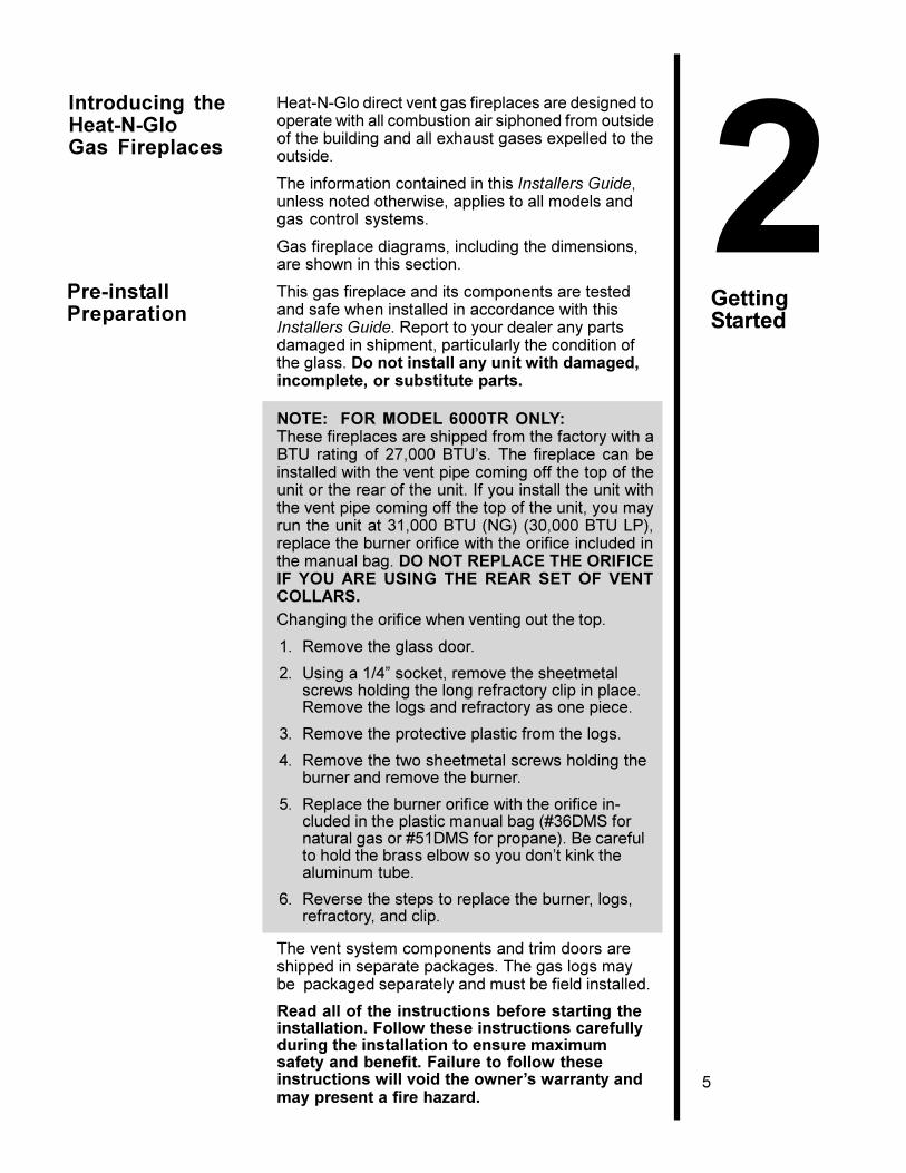
2GettingStarted
Heat-N-Glo direct vent gas fireplaces are designed tooperate with all combustion air siphoned from outsideof the building and all exhaust gases expelled to theoutside.
The information contained in this Installers Guide,unless noted otherwise, applies to all models andgas control systems.
Gas fireplace diagrams, including the dimensions,are shown in this section.
This gas fireplace and its components are testedand safe when installed in accordance with thisInstallers Guide. Report to your dealer any partsdamaged in shipment, particularly the condition ofthe glass. Do not install any unit with damaged,incomplete, or substitute parts.
NOTE: FOR MODEL 6000TR ONLY:These fireplaces are shipped from the factory with aBTU rating of 27,000 BTU�s. The fireplace can beinstalled with the vent pipe coming off the top of theunit or the rear of the unit. If you install the unit withthe vent pipe coming off the top of the unit, you mayrun the unit at 31,000 BTU (NG) (30,000 BTU LP),replace the burner orifice with the orifice included inthe manual bag. DO NOT REPLACE THE ORIFICEIF YOU ARE USING THE REAR SET OF VENTCOLLARS.Changing the orifice when venting out the top.
1. Remove the glass door.
2. Using a 1/4� socket, remove the sheetmetalscrews holding the long refractory clip in place.Remove the logs and refractory as one piece.
3. Remove the protective plastic from the logs.
4. Remove the two sheetmetal screws holding theburner and remove the burner.
5. Replace the burner orifice with the orifice in-cluded in the plastic manual bag (#36DMS fornatural gas or #51DMS for propane). Be carefulto hold the brass elbow so you don�t kink thealuminum tube.
6. Reverse the steps to replace the burner, logs,refractory, and clip.
The vent system components and trim doors areshipped in separate packages. The gas logs maybe packaged separately and must be field installed.
Read all of the instructions before starting theinstallation. Follow these instructions carefullyduring the installation to ensure maximumsafety and benefit. Failure to follow theseinstructions will void the owner�s warranty andmay present a fire hazard.
Introducing theHeat-N-GloGas Fireplaces
Pre-installPreparation
6
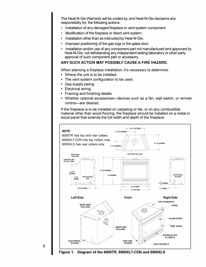
Figure 1. Diagram of the 6000TR, 6000XLT-CDN and 6000XLS
The Heat-N-Glo Warranty will be voided by, and Heat-N-Glo disclaims anyresponsibility for, the following actions:
� Installation of any damaged fireplace or vent system component.
� Modification of the fireplace or direct vent system.
� Installation other than as instructed by Heat-N-Glo.
� Improper positioning of the gas logs or the glass door.
� Installation and/or use of any component part not manufactured and approved byHeat-N-Glo, not withstanding any independent testing laboratory or other partyapproval of such component part or accessory.
ANY SUCH ACTION MAY POSSIBLY CAUSE A FIRE HAZARD.
When planning a fireplace installation, it�s necessary to determine:� Where the unit is to be installed.� The vent system configuration to be used.� Gas supply piping.� Electrical wiring.� Framing and finishing details.� Whether optional accessories�devices such as a fan, wall switch, or remote
control�are desired.
If the fireplace is to be installed on carpeting or tile, or on any combustiblematerial other than wood flooring, the fireplace should be installed on a metal orwood panel that extends the full width and depth of the fireplace.
Left Side Front Right Side
NOTE:6000TR has top and rear collars.
6000XLT-CDN has top collars only.
6000XLS has rear collars only.
7
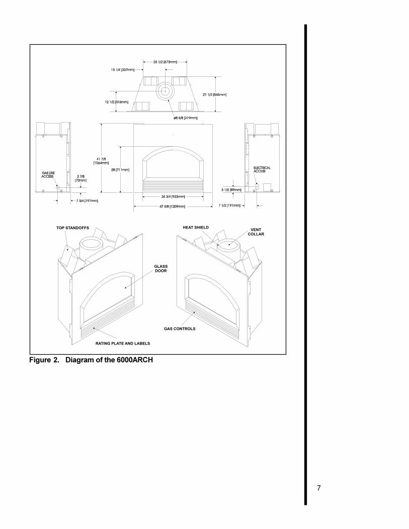
Figure 2. Diagram of the 6000ARCH
8
3Installing theFireplace
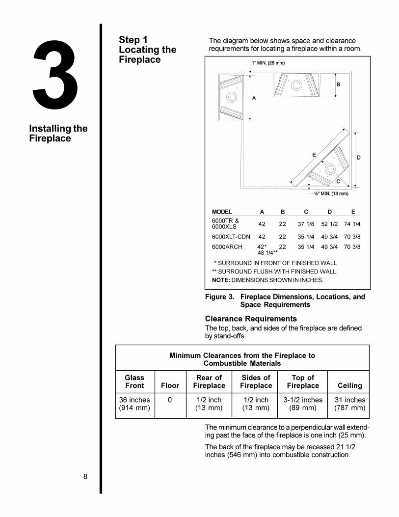
Step 1Locating theFireplace
The diagram below shows space and clearancerequirements for locating a fireplace within a room.
MODEL A B C D E
6000TR &42 22 37 1/8 52 1/2 74 1/46000XLS
6000XLT-CDN 42 22 35 1/4 49 3/4 70 3/8
6000ARCH 42* 22 35 1/4 49 3/4 70 3/8 48 1/4**
* SURROUND IN FRONT OF FINISHED WALL
** SURROUND FLUSH WITH FINISHED WALL.
NOTE: DIMENSIONS SHOWN IN INCHES.
Figure 3. Fireplace Dimensions, Locations, andSpace Requirements
Clearance RequirementsThe top, back, and sides of the fireplace are definedby stand-offs.
Minimum Clearances from the Fireplace toCombustible Materials
Glass Rear of Sides of Top ofFront Floor Fireplace Fireplace Fireplace Ceiling
36 inches 0 1/2 inch 1/2 inch 3-1/2 inches 31 inches(914 mm) (13 mm) (13 mm) (89 mm) (787 mm)
The minimum clearance to a perpendicular wall extend-ing past the face of the fireplace is one inch (25 mm).
The back of the fireplace may be recessed 21 1/2inches (546 mm) into combustible construction.
9
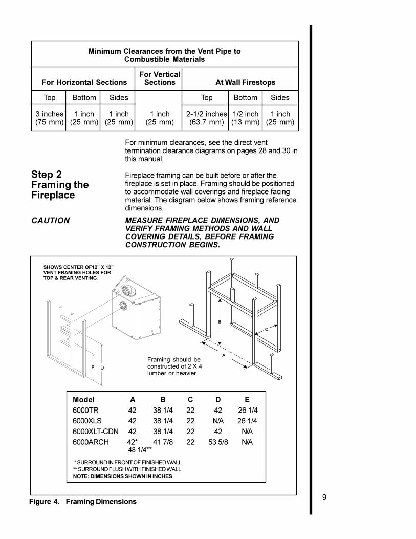
A
B
C
Framing should beconstructed of 2 X 4lumber or heavier.
Model A B C D E6000TR 42 38 1/4 22 42 26 1/4
6000XLS 42 38 1/4 22 N/A 26 1/4
6000XLT-CDN 42 38 1/4 22 42 N/A
6000ARCH 42* 41 7/8 22 53 5/8 N/A 48 1/4**
* SURROUND IN FRONT OF FINISHED WALL** SURROUND FLUSH WITH FINISHED WALLNOTE: DIMENSIONS SHOWN IN INCHES
DE
SHOWS CENTER OF12" X 12"VENT FRAMING HOLES FORTOP & REAR VENTING.
Figure 4. Framing Dimensions
Minimum Clearances from the Vent Pipe toCombustible Materials
For VerticalFor Horizontal Sections Sections At Wall Firestops
Top Bottom Sides Top Bottom Sides
3 inches 1 inch 1 inch 1 inch 2-1/2 inches 1/2 inch 1 inch(75 mm) (25 mm) (25 mm) (25 mm) (63.7 mm) (13 mm) (25 mm)
For minimum clearances, see the direct venttermination clearance diagrams on pages 28 and 30 inthis manual.
Step 2Framing theFireplace
Fireplace framing can be built before or after thefireplace is set in place. Framing should be positionedto accommodate wall coverings and fireplace facingmaterial. The diagram below shows framing referencedimensions.
CAUTION MEASURE FIREPLACE DIMENSIONS, ANDVERIFY FRAMING METHODS AND WALLCOVERING DETAILS, BEFORE FRAMINGCONSTRUCTION BEGINS.
10
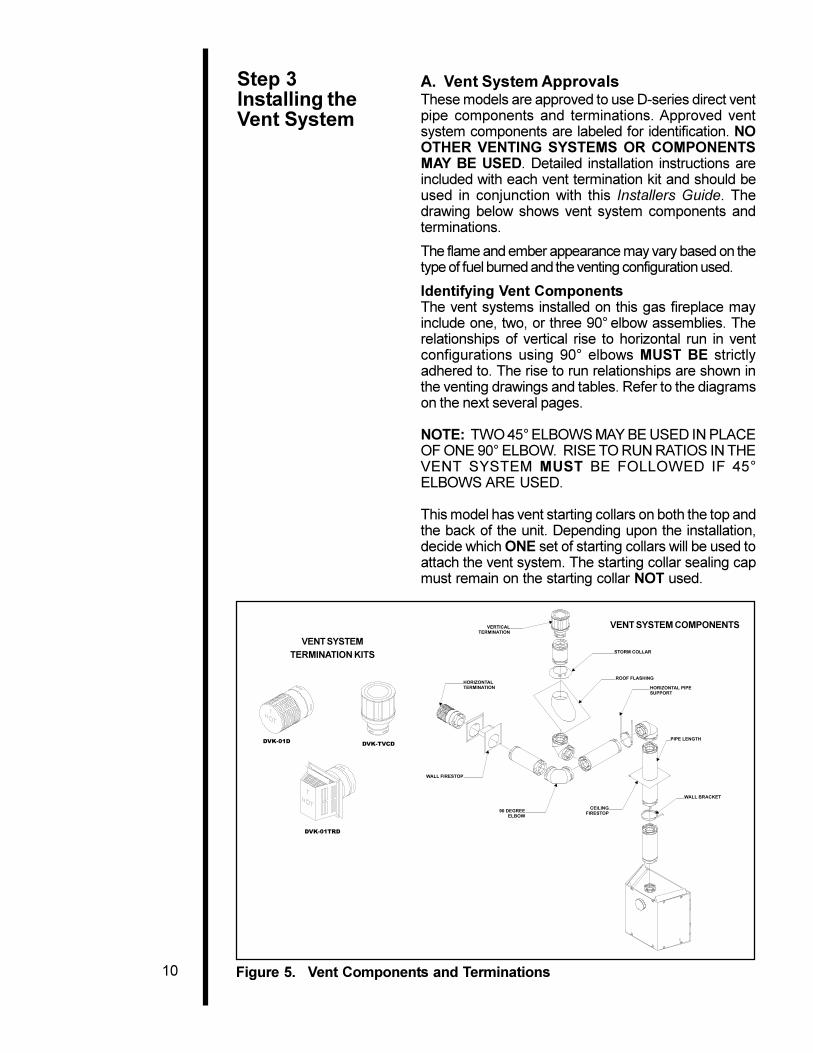
VENT SYSTEMTERMINATION KITS
VENT SYSTEM COMPONENTS
Figure 5. Vent Components and Terminations
Step 3Installing theVent System
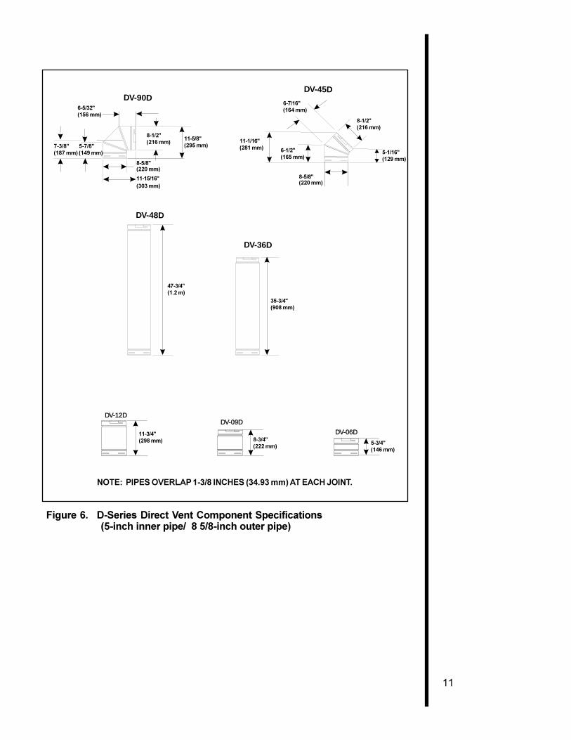
A. Vent System ApprovalsThese models are approved to use D-series direct ventpipe components and terminations. Approved ventsystem components are labeled for identification. NOOTHER VENTING SYSTEMS OR COMPONENTSMAY BE USED. Detailed installation instructions areincluded with each vent termination kit and should beused in conjunction with this Installers Guide. Thedrawing below shows vent system components andterminations.
The flame and ember appearance may vary based on thetype of fuel burned and the venting configuration used.
Identifying Vent ComponentsThe vent systems installed on this gas fireplace mayinclude one, two, or three 90° elbow assemblies. Therelationships of vertical rise to horizontal run in ventconfigurations using 90° elbows MUST BE strictlyadhered to. The rise to run relationships are shown inthe venting drawings and tables. Refer to the diagramson the next several pages.
NOTE: TWO 45° ELBOWS MAY BE USED IN PLACEOF ONE 90° ELBOW. RISE TO RUN RATIOS IN THEVENT SYSTEM MUST BE FOLLOWED IF 45°ELBOWS ARE USED.
This model has vent starting collars on both the top andthe back of the unit. Depending upon the installation,decide which ONE set of starting collars will be used toattach the vent system. The starting collar sealing capmust remain on the starting collar NOT used.
11
DV-90D
6 5/32
5 7/87 3/8
DV-45D
6 7/16
11 1/166 1/2
8 5/8
8 1/2
5 1/16
8 /12 11 5/8
8 5/8
11 15/16
DV-36D
35 3/4
47 3/4
DV-48D
5 3/48 3/411 3/4
DV-12DDV-09D
DV-06D
6-5/32"(156 mm)
7-3/8" 5-7/8"(187 mm) (149 mm)
8-1/2"(216 mm)
8-5/8"(220 mm)
11-15/16"(303 mm)
11-5/8"(295 mm)
11-1/16"(281 mm) 6-1/2"
(165 mm)
8-5/8"(220 mm)
5-1/16"(129 mm)
8-1/2"(216 mm)
6-7/16"(164 mm)
35-3/4"(908 mm)
47-3/4"(1.2 m)
11-3/4"(298 mm) 8-3/4"
(222 mm)5-3/4"(146 mm)
NOTE: PIPES OVERLAP 1-3/8 INCHES (34.93 mm) AT EACH JOINT.
Figure 6. D-Series Direct Vent Component Specifications (5-inch inner pipe/ 8 5/8-inch outer pipe)

12
Figure 7. Straight Up Vertical Venting
STRAIGHT UPVERTICAL VENTING
V (FT.)
40' MAX. (12.4 M)
NOTE: Model 6000ARCHA 12-inch length of straight ventpipe MUST be the first ventcomponent attached to the unit.
13
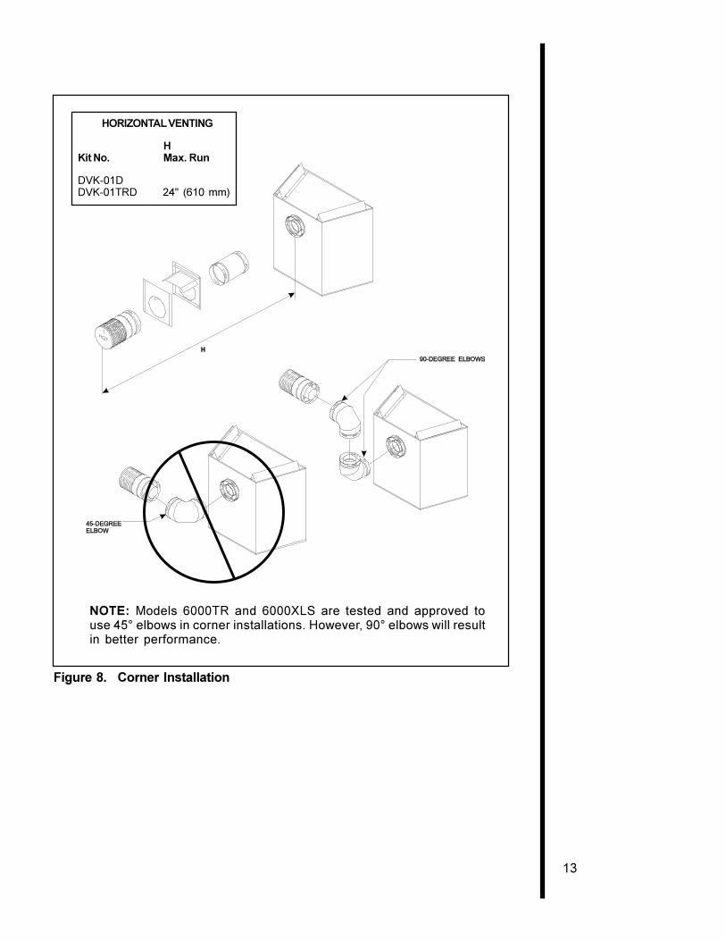
HORIZONTAL VENTING
HKit No. Max. Run
DVK-01DDVK-01TRD 24" (610 mm)
NOTE: Models 6000TR and 6000XLS are tested and approved touse 45° elbows in corner installations. However, 90° elbows will resultin better performance.
Figure 8. Corner Installation

14
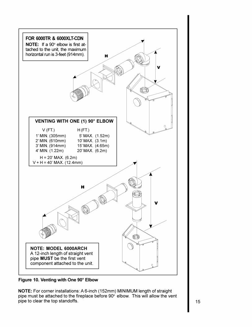
VENTING WITH ONE (1) 90° ELBOW
V (FT.) H (FT.)
1' MIN. (305mm) 2' MAX. (610mm) 2' MIN. (610mm) 4' MAX. (1.22m) 3' MIN. (914mm) 6' MAX. (1.86m) 4' MIN. (1.22m) 8' MAX. (2.4m)
H = 8' MAX. (2.4m) V+H = 40' MAX. (12.4m)
Figure 9. Venting with One 90° Elbow
15
VENTING WITH ONE (1) 90° ELBOW
V (FT.) H (FT.)
1' MIN. (305mm) 5' MAX. (1.52m) 2' MIN. (610mm) 10' MAX. (3.1m) 3' MIN. (914mm) 15' MAX. (4.65m) 4' MIN. (1.22m) 20' MAX. (6.2m)
H = 20' MAX. (6.2m)V + H = 40� MAX. (12.4mm)
Figure 10. Venting with One 90° Elbow
FOR 6000TR & 6000XLT-CDNNOTE: If a 90o elbow is first at-tached to the unit, the maximumhorizontal run is 3-feet (914mm).
NOTE: For corner installations: A 6-inch (152mm) MINIMUM length of straightpipe must be attached to the fireplace before 90o elbow. This will allow the ventpipe to clear the top standoffs.
NOTE: MODEL 6000ARCHA 12-inch length of straight ventpipe MUST be the first ventcomponent attached to the unit.
16
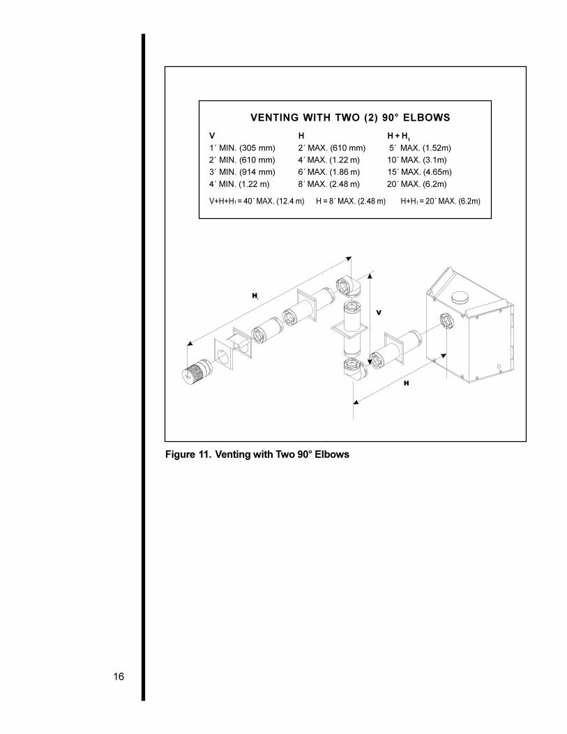
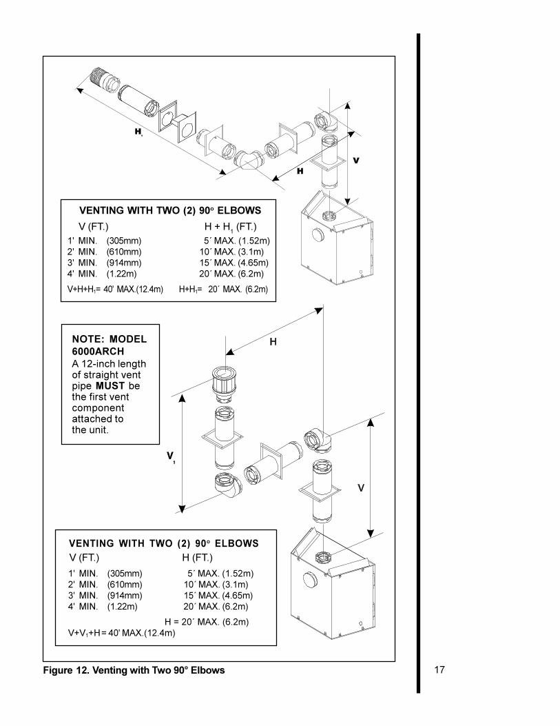
VENTING WITH TWO (2) 90° ELBOWS
V H H + H1
1´ MIN. (305 mm) 2´ MAX. (610 mm) 5´ MAX. (1.52m)
2´ MIN. (610 mm) 4´ MAX. (1.22 m) 10´ MAX. (3.1m)
3´ MIN. (914 mm) 6´ MAX. (1.86 m) 15´ MAX. (4.65m)
4´ MIN. (1.22 m) 8´ MAX. (2.48 m) 20´ MAX. (6.2m)
V+H+H1 = 40´ MAX. (12.4 m) H = 8´ MAX. (2.48 m) H+H1 = 20´ MAX. (6.2m)
Figure 11. Venting with Two 90° Elbows
17
VENTING WITH TWO (2) 90o ELBOWS
V (FT.) H + H1 (FT.)
1' MIN. (305mm) 5´ MAX. (1.52m)2' MIN. (610mm) 10´ MAX. (3.1m)3' MIN. (914mm) 15´ MAX. (4.65m)4' MIN. (1.22m) 20´ MAX. (6.2m)
V+H+H1= 40' MAX.(12.4m) H+H1= 20´ MAX. (6.2m)
Figure 12. Venting with Two 90° Elbows
NOTE: MODEL6000ARCHA 12-inch lengthof straight ventpipe MUST bethe first ventcomponentattached tothe unit.
VENTING WITH TWO (2) 90o ELBOWS V (FT.) H (FT.)
1' MIN. (305mm) 5´ MAX. (1.52m)2' MIN. (610mm) 10´ MAX. (3.1m)3' MIN. (914mm) 15´ MAX. (4.65m)4' MIN. (1.22m) 20´ MAX. (6.2m)
H = 20´ MAX. (6.2m)V+V1+H = 40' MAX.(12.4m)
18
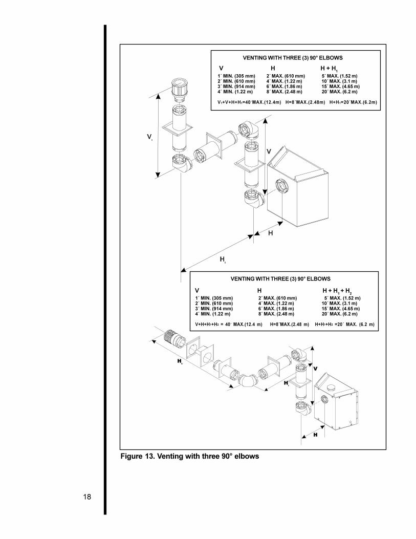
1´ MIN. (305 mm) 2´ MAX. (610 mm) 5´ MAX. (1.52 m)2´ MIN. (610 mm) 4´ MAX. (1.22 m) 10´ MAX. (3.1 m)3´ MIN. (914 mm) 6´ MAX. (1.86 m) 15´ MAX. (4.65 m)4´ MIN. (1.22 m) 8´ MAX. (2.48 m) 20´ MAX. (6.2 m)
V+H+H1+H2 = 40´ MAX.(12.4 m) H=8´MAX.(2.48 m) H+H1+H2 =20´ MAX. (6.2 m)
VENTING WITH THREE (3) 90° ELBOWS
V H H + H1 + H2
1´ MIN. (305 mm) 2´ MAX. (610 mm) 5´ MAX. (1.52 m)2´ MIN. (610 mm) 4´ MAX. (1.22 m) 10´ MAX. (3.1 m)3´ MIN. (914 mm) 6´ MAX. (1.86 m) 15´ MAX. (4.65 m)4´ MIN. (1.22 m) 8´ MAX. (2.48 m) 20´ MAX. (6.2 m)
V1+V+H+H1=40´MAX.(12.4m) H=8´MAX.(2.48m) H+H1=20´MAX.(6.2m)
VENTING WITH THREE (3) 90° ELBOWS
V H H + H1
Figure 13. Venting with three 90° elbows
19
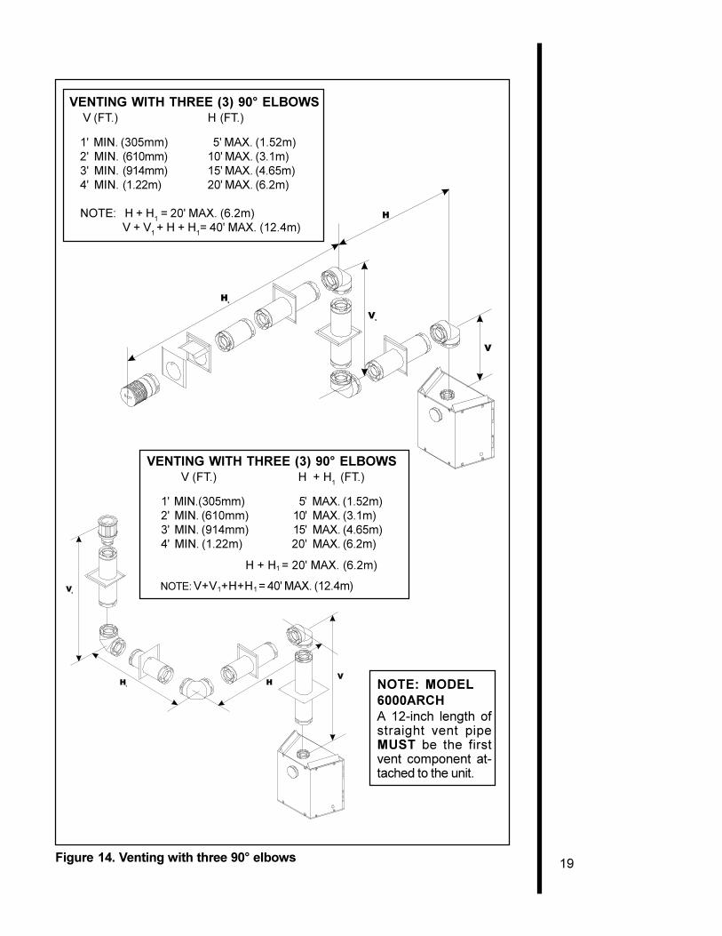
VENTING WITH THREE (3) 90° ELBOWS V (FT.) H
(FT.)
1' MIN. (305mm) 5' MAX. (1.52m)2' MIN. (610mm) 10' MAX. (3.1m)3' MIN. (914mm) 15' MAX. (4.65m)4' MIN. (1.22m) 20' MAX. (6.2m)
NOTE: H + H1 = 20' MAX. (6.2m)V + V1 + H + H1= 40' MAX. (12.4m)
VENTING WITH THREE (3) 90° ELBOWS V (FT.) H + H
1 (FT.)
1' MIN.(305mm) 5' MAX. (1.52m)2' MIN. (610mm) 10' MAX. (3.1m)3' MIN. (914mm) 15' MAX. (4.65m)4' MIN. (1.22m) 20' MAX. (6.2m)
H + H1 = 20' MAX. (6.2m)
NOTE: V+V1+H+H1 = 40' MAX. (12.4m)
Figure 14. Venting with three 90° elbows
NOTE: MODEL6000ARCHA 12-inch length ofstraight vent pipeMUST be the firstvent component at-tached to the unit.
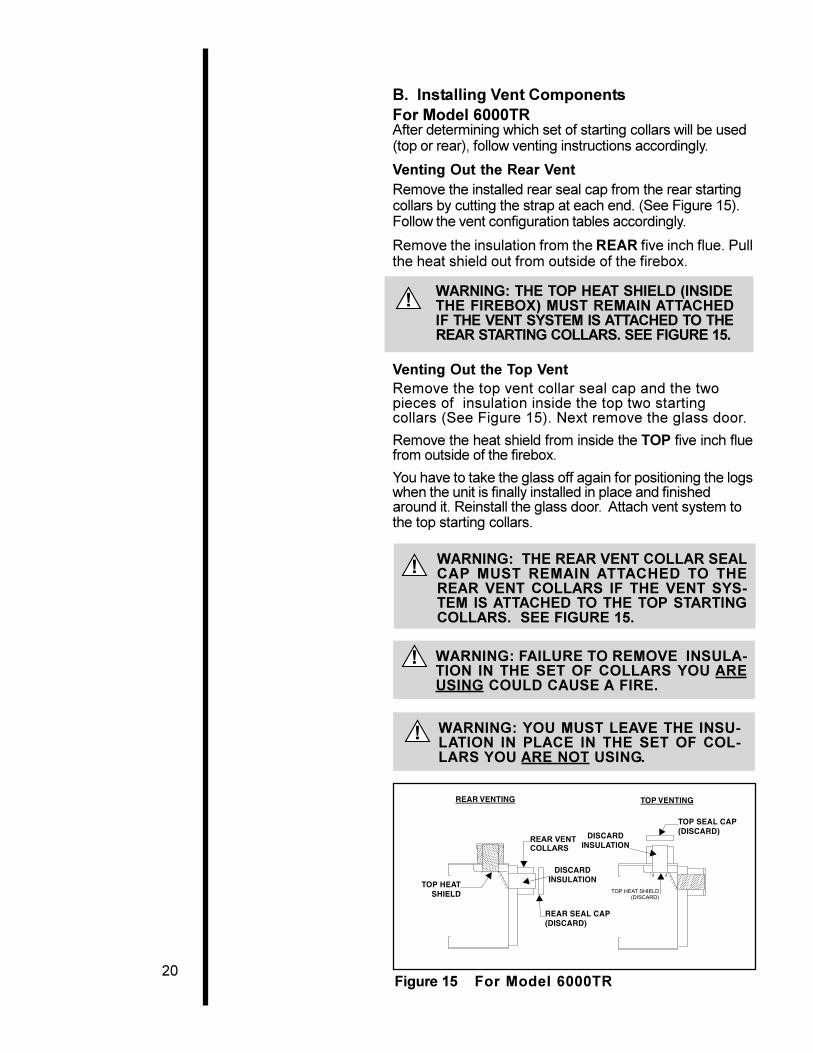
20Figure 15 For Model 6000TR
B. Installing Vent ComponentsFor Model 6000TRAfter determining which set of starting collars will be used(top or rear), follow venting instructions accordingly.
Venting Out the Rear VentRemove the installed rear seal cap from the rear startingcollars by cutting the strap at each end. (See Figure 15).Follow the vent configuration tables accordingly.
Remove the insulation from the REAR five inch flue. Pullthe heat shield out from outside of the firebox.
WARNING: THE TOP HEAT SHIELD (INSIDETHE FIREBOX) MUST REMAIN ATTACHEDIF THE VENT SYSTEM IS ATTACHED TO THEREAR STARTING COLLARS. SEE FIGURE 15.
Venting Out the Top VentRemove the top vent collar seal cap and the twopieces of insulation inside the top two startingcollars (See Figure 15). Next remove the glass door.
Remove the heat shield from inside the TOP five inch fluefrom outside of the firebox.
You have to take the glass off again for positioning the logswhen the unit is finally installed in place and finishedaround it. Reinstall the glass door. Attach vent system tothe top starting collars.
WARNING: FAILURE TO REMOVE INSULA-TION IN THE SET OF COLLARS YOU AREUSING COULD CAUSE A FIRE.
WARNING: THE REAR VENT COLLAR SEALCAP MUST REMAIN ATTACHED TO THEREAR VENT COLLARS IF THE VENT SYS-TEM IS ATTACHED TO THE TOP STARTINGCOLLARS. SEE FIGURE 15.
WARNING: YOU MUST LEAVE THE INSU-LATION IN PLACE IN THE SET OF COL-LARS YOU ARE NOT USING.
!
!
!
!
21
WARNING: ENSURE THAT THE FIBER-GLASS ROPE GASKET SUPPLIED WITHTHE FIREPLACE SEALS BETWEEN THEFIRST VENT COMPONENT & THE OUTERFIREPLACE WRAP.
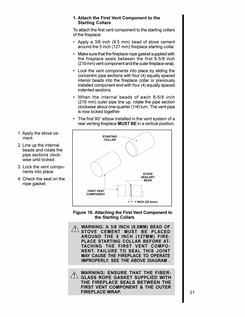
1. Attach the First Vent Component to theStarting Collars
To attach the first vent component to the starting collarsof the fireplace:
� Apply a 3/8 inch (9.5 mm) bead of stove cementaround the 5 inch (127 mm) fireplace starting collar.
� Make sure that the fireplace rope gasket supplied withthe fireplace seals between the first 8-5/8 inch(219 mm) vent component and the outer fireplace wrap.
� Lock the vent components into place by sliding theconcentric pipe sections with four (4) equally spacedinterior beads into the fireplace collar or previouslyinstalled component end with four (4) equally spacedindented sections.
� When the internal beads of each 8-5/8 inch(219 mm) outer pipe line up, rotate the pipe sectionclockwise about one-quarter (1/4) turn. The vent pipeis now locked together.
� The first 90° elbow installed in the vent system of arear venting fireplace MUST BE in a vertical position.
1. Apply the stove ce-ment.
2. Line up the internalbeads and rotate thepipe sections clock-wise until locked.
3. Lock the vent compo-nents into place.
4. Check the seal on therope gasket.
Figure 16. Attaching the First Vent Component tothe Starting Collars
WARNING: A 3/8 INCH (9.5MM) BEAD OFSTOVE CEMENT MUST BE PLACEDAROUND THE 5 INCH (127MM) FIRE-PLACE STARTING COLLAR BEFORE AT-TACHING THE FIRST VENT COMPO-NENT. FAILURE TO SEAL THIS JOINTMAY CAUSE THE FIREPLACE TO OPERATEIMPROPERLY. SEE THE ABOVE DIAGRAM .
!
!
STARTINGCOLLAR
STOVESEALANT
BEAD
1 INCH (25.4mm)
FIRST VENTCOMPONENT
22
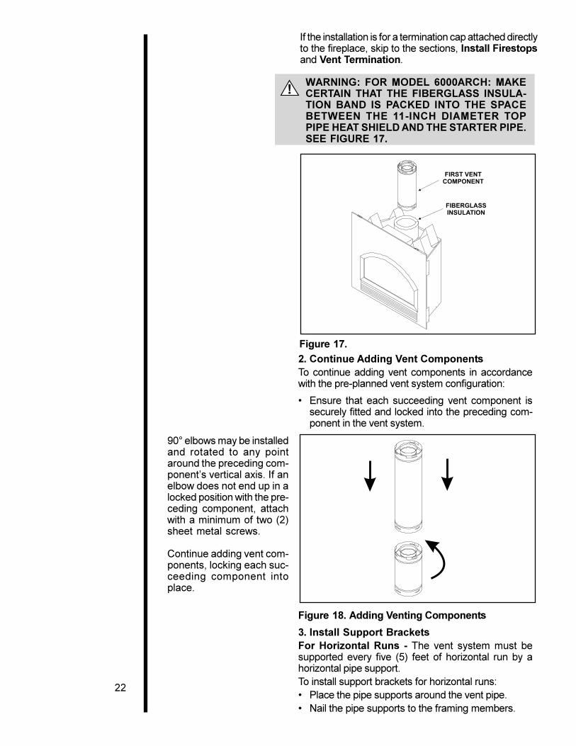
2. Continue Adding Vent ComponentsTo continue adding vent components in accordancewith the pre-planned vent system configuration:
� Ensure that each succeeding vent component issecurely fitted and locked into the preceding com-ponent in the vent system.
Figure 18. Adding Venting Components
3. Install Support BracketsFor Horizontal Runs - The vent system must besupported every five (5) feet of horizontal run by ahorizontal pipe support.To install support brackets for horizontal runs:� Place the pipe supports around the vent pipe.� Nail the pipe supports to the framing members.
Figure 17.
If the installation is for a termination cap attached directlyto the fireplace, skip to the sections, Install Firestopsand Vent Termination.
WARNING: FOR MODEL 6000ARCH: MAKECERTAIN THAT THE FIBERGLASS INSULA-TION BAND IS PACKED INTO THE SPACEBETWEEN THE 11-INCH DIAMETER TOPPIPE HEAT SHIELD AND THE STARTER PIPE.SEE FIGURE 17.
90° elbows may be installedand rotated to any pointaround the preceding com-ponent�s vertical axis. If anelbow does not end up in alocked position with the pre-ceding component, attachwith a minimum of two (2)sheet metal screws.
Continue adding vent com-ponents, locking each suc-ceeding component intoplace.
!
23
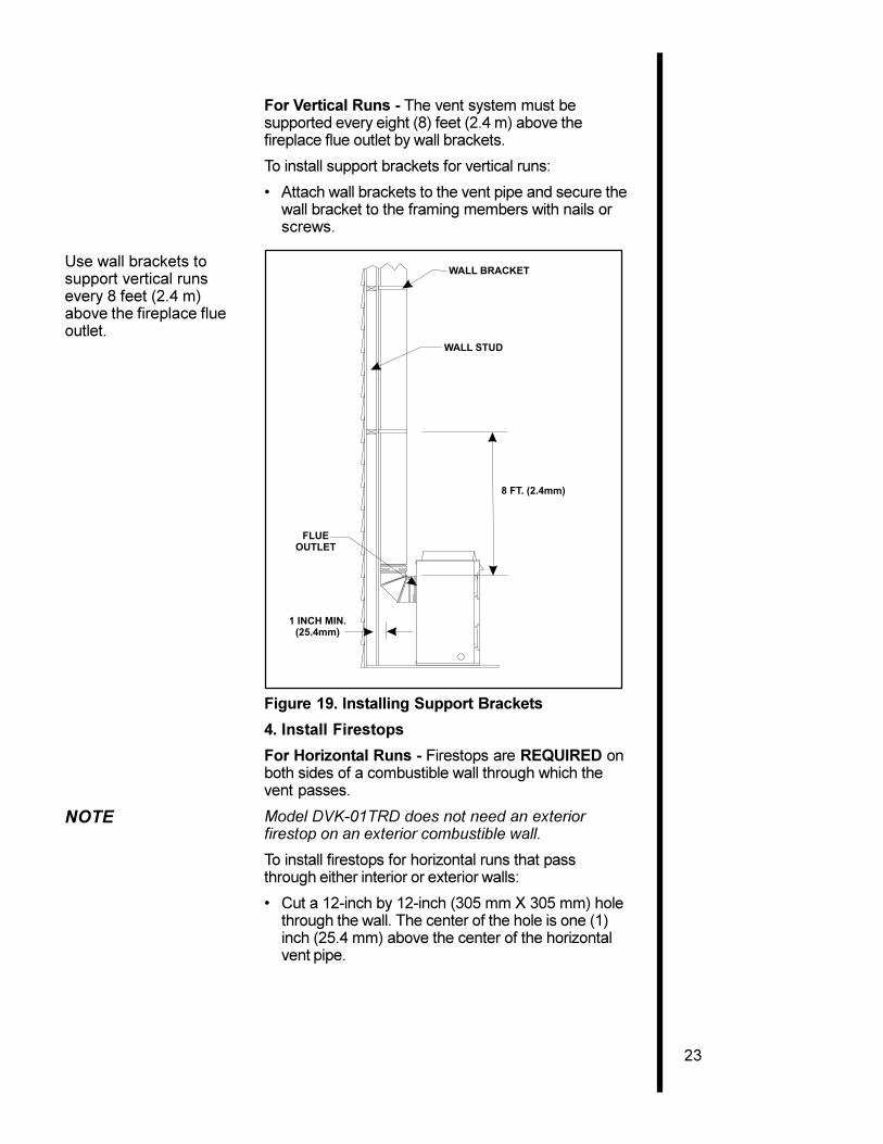
For Vertical Runs - The vent system must besupported every eight (8) feet (2.4 m) above thefireplace flue outlet by wall brackets.
To install support brackets for vertical runs:
� Attach wall brackets to the vent pipe and secure thewall bracket to the framing members with nails orscrews.
Use wall brackets tosupport vertical runsevery 8 feet (2.4 m)above the fireplace flueoutlet.
Figure 19. Installing Support Brackets
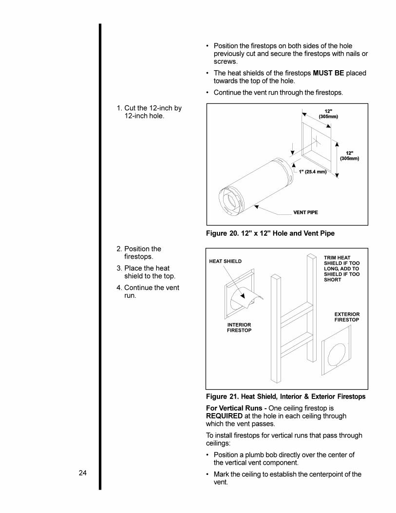
4. Install Firestops
For Horizontal Runs - Firestops are REQUIRED onboth sides of a combustible wall through which thevent passes.
NOTE Model DVK-01TRD does not need an exteriorfirestop on an exterior combustible wall.
To install firestops for horizontal runs that passthrough either interior or exterior walls:
� Cut a 12-inch by 12-inch (305 mm X 305 mm) holethrough the wall. The center of the hole is one (1)inch (25.4 mm) above the center of the horizontalvent pipe.
1 INCH MIN.(25.4mm)
FLUEOUTLET
WALL BRACKET
WALL STUD
8 FT. (2.4mm)
24
TRIM HEATSHIELD IF TOOLONG, ADD TOSHIELD IF TOOSHORT
EXTERIORFIRESTOP
INTERIORFIRESTOP
HEAT SHIELD
Figure 20. 12" x 12" Hole and Vent Pipe
2. Position thefirestops.
3. Place the heatshield to the top.
4. Continue the ventrun.
Figure 21. Heat Shield, Interior & Exterior Firestops
For Vertical Runs - One ceiling firestop isREQUIRED at the hole in each ceiling throughwhich the vent passes.
To install firestops for vertical runs that pass throughceilings:
� Position a plumb bob directly over the center ofthe vertical vent component.
� Mark the ceiling to establish the centerpoint of thevent.
� Position the firestops on both sides of the holepreviously cut and secure the firestops with nails orscrews.
� The heat shields of the firestops MUST BE placedtowards the top of the hole.
� Continue the vent run through the firestops.
1. Cut the 12-inch by12-inch hole.
25
� Drill a hole or drive a nail through this centerpoint.
� Check the floor above for any obstructions, such aswiring or plumbing runs.
� Reposition the fireplace and vent system, if neces-sary, to accommodate the ceiling joists and/orobstructions.
� Cut an 11-inch X 11-inch (280 mm X 280 mm) holethrough the ceiling, using the centerpoint previouslymarked.
� Frame the hole with framing lumber the same sizeas the ceiling joists.
1. Cut the 11-inch by11-inch hole.
2. Add the new framingmembers.
JOIST
CEILING FIRESTOP
CEILING
NAILS (4 REQUIRED)
Figure 22. 11" x 11" Hole and New FramingMembers
If the area above the ceiling is NOT an attic, positionand secure the ceiling firestop on the ceiling side ofthe previously cut and framed hole.
This shows a ceilinginstallation.
Figure 23. Ceiling Firestop (Ceiling Side)
26
JOIST
CEILING FIRESTOP
CEILING
NAILS (4 REQUIRED)
!
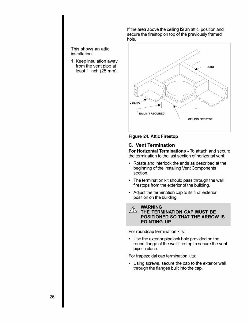
If the area above the ceiling IS an attic, position andsecure the firestop on top of the previously framedhole.
This shows an atticinstallation.
1. Keep insulation awayfrom the vent pipe atleast 1 inch (25 mm).
Figure 24. Attic Firestop
C. Vent TerminationFor Horizontal Terminations - To attach and securethe termination to the last section of horizontal vent:
� Rotate and interlock the ends as described at thebeginning of the Installing Vent Componentssection.
� The termination kit should pass through the wallfirestops from the exterior of the building.
� Adjust the termination cap to its final exteriorposition on the building.
WARNINGTHE TERMINATION CAP MUST BEPOSITIONED SO THAT THE ARROW ISPOINTING UP.
For roundcap termination kits:
� Use the exterior pipelock hole provided on theround flange of the wall firestop to secure the ventpipe in place.
For trapezoidal cap termination kits:
� Using screws, secure the cap to the exterior wallthrough the flanges built into the cap.

27
For round captermination:
1. Secure the 8-5/8inch (219 mm) pipe,using the exteriorpipelock hole on theround flange of thewall firestop.
For trapezoidaltermination:
1. Screw the cap to theexterior wall throughthe flanges in thecap.
2. Seal the joint be-tween the pipe andthe exterior firestop.
Figure 25. Round & Trapezoid Termination Caps
WARNING: THE BOTTOM OF THEVENT TERMINATION CAP MUST BE AMINIMUM OF 12 INCHES (305MM)ABOVE GROUND LEVEL (GRADE). THETOP OF THE CAP MUST BE A MINIMUMOF 18 INCHES (457MM) BELOW COM-BUSTIBLE MATERIAL, SUCH AS ADECK, AND THE SIDE OF THE CAPMUST BE A MINIMUM OF 6 INCHES(152MM) AWAY FROM A PARALLEL OUT-SIDE WALL. VENTING TERMINALSSHALL NOT BE RECESSED INTO AWALL OR SIDING. SEE THE FOLLOW-ING DIAGRAM FOR VENT TERMINA-TION CLEARANCES.
!
ROUND CAP TERMINATION
PERFORATION CANNOT BEINSIDE THE WALL
7 1/2"(191mm)MINIMUM
TRAPEZOID CAP TERMINATION
7 1/4"(184mm)

28
V =VENT TERMINAL
X =AIR SUPPLY INLET
12341234123412341234
=AREA WHERE TERMINAL IS NOT PERMITTED
A = 12" clearances above grade, veranda, porch, deck or balcony
B = 12" clearances to window or door that may be opened
C = 9" (U.S.A.) clearance to permanently closed window12" (Canada)
*D = 18" vertical clearance to ventilated soffit located above theterminal within a horizontal distance of 2 feet (60 cm)from the center-line of the terminal
*E = 18" clearance to unventilated soffit
F = 9" clearance to outside corner
G = 6" clearance to inside corner
H = 3 ft. (Canada) not to be installed above a gas meter/regulator assemblywithin 3 feet (90 cm) horizontally from the center-line ofthe regulator
I = 3 ft. (U.S.A.) clearance to service regulator vent outlet6 ft. (Canada)
J = 9" (U.S.A.) clearance to non-mechanical air supply inlet to building12" (Canada) or the combustion air inlet to any other appliance
K = 3 ft. (U.S.A.) clearance to a mechanical air supply inlet6 ft. (Canada)
**L = 7 ft. clearance above paved sidewalk or a paved drivewaylocated on public property
***M = 18" clearance under veranda, porch, deck or balcony
* 30� minimum for vinyl clad soffits.
** a vent shall not terminate directly above a sidewalk or paved driveway which islocated between two single family dwellings and serves both dwellings.
*** only permitted if veranda, porch, deck or balcony is fully open on a minimum of2 sides beneath the floor.
NOTE: Local Codes or Regulations may require different clearances.
Figure 26. Vent Termination Minimum Clearances
CAUTION IF EXTERIOR WALLS ARE FINISHED WITHVINYL SIDING, IT IS NECESSARY TO INSTALLTHE VINYL PROTECTOR KIT TO THE TOP OFTHE EXTERIOR FIRESTOP (FOR ALL ROUNDTERMINATION CAPS).
D
E
BL
v
vv
v
v
v
v
v
openableC
B B
B
fixed closed
A H
MX
J or K
I
A
G
F
29
!
For Vertical Terminations - To locate the vent andinstall the vent sections:
� Locate and mark the vent centerpoint on the under-side of the roof, and drive a nail through thecenterpoint.
� Make the outline of the roof hole around thecenterpoint nail.
� The size of the roof hole framing dimensionsdepend on the pitch of the roof. There MUST BE a1-inch (25.4 mm) clearance from the vertical ventpipe to combustible materials.
� Mark the roof hole accordingly.
� Cover the opening of the installed vent pipes.
� Cut and frame the roof hole.
� Use framing lumber the same size as the roofrafters and install the frame securely. Flashinganchored to the frame must withstand heavy winds.
� Continue to install concentric vent sections upthrough the roof hole (for inside vent installations) orup past the roof line until you reach the appropriatedistance above the roof (for outside terminations).
WARNING:MAJOR U.S. BUILDING CODES SPECI-FY MINIMUM CHIMNEY AND/OR VENTHEIGHT ABOVE THE ROOF TOP. THESEMINIMUM HEIGHTS ARE NECESSARY INTHE INTEREST OF SAFETY. SEE THEFOLLOWING DIAGRAM FOR MINIMUMHEIGHTS, PROVIDED THE TERMINA-TION CAP IS AT LEAST TWO (2) FEETFROM A VERTICAL WALL AND 2-FEETBELOW A HORIZONTAL OVERHANG.
NOTE This also pertains to vertical vent systems installedon the outside of the building.
30
TERMINATIONCAP
To seal the roof hole, and to divert rain and snow fromthe vent system:
� Attach a flashing to the roof using nails, and use anon-hardening mastic around the edges of theflashing base where it meets the roof.
� Attach a storm collar over the flashing joint to form awater-tight seal. Place non-hardening masticaround the joint, between the storm collar and thevertical pipe.
� Slide the termination cap over the end of the ventpipe and rotate the pipe clockwise 1/4 turn.
1. Attach the flashingand apply sealantaround the edges ofthe flashing base.
2. Attach the stormcollar over the flashingjoint and apply sealantbetween the stormcollar and verticalpipe.
HORIZONTAL OVERHANG
VERTICAL WALL
TERMINATION CAP
12X
ROOF PITCH IS X/ 12
LOWEST DISCHARGE OPENING
H (MIN.) - MINIMUM HEIGHT FROM ROOFTO LOWEST DISCHARGE OPENING
2 FT.MIN.
2 FT. MIN.
Roof Pitch H (min.) ft.
flat to 6/12 1.06/12 to 7/12 1.25over 7/12 to 8/12 1.5over 8/12 to 9/12 2.0over 9/12 to 10/12 2.5over 10/12 to 11/12 3.25over 11/12 to 12/12 4.0over 12/12 to 14/12 5.0over 14/12 to 16/12 6.0over 16/12 to 18/12 7.0over 18/12 to 20/12 7.5over 20/12 to 21/12 8.0
Figure 27. Minimum Height from Roof to LowestDischarge Opening
31
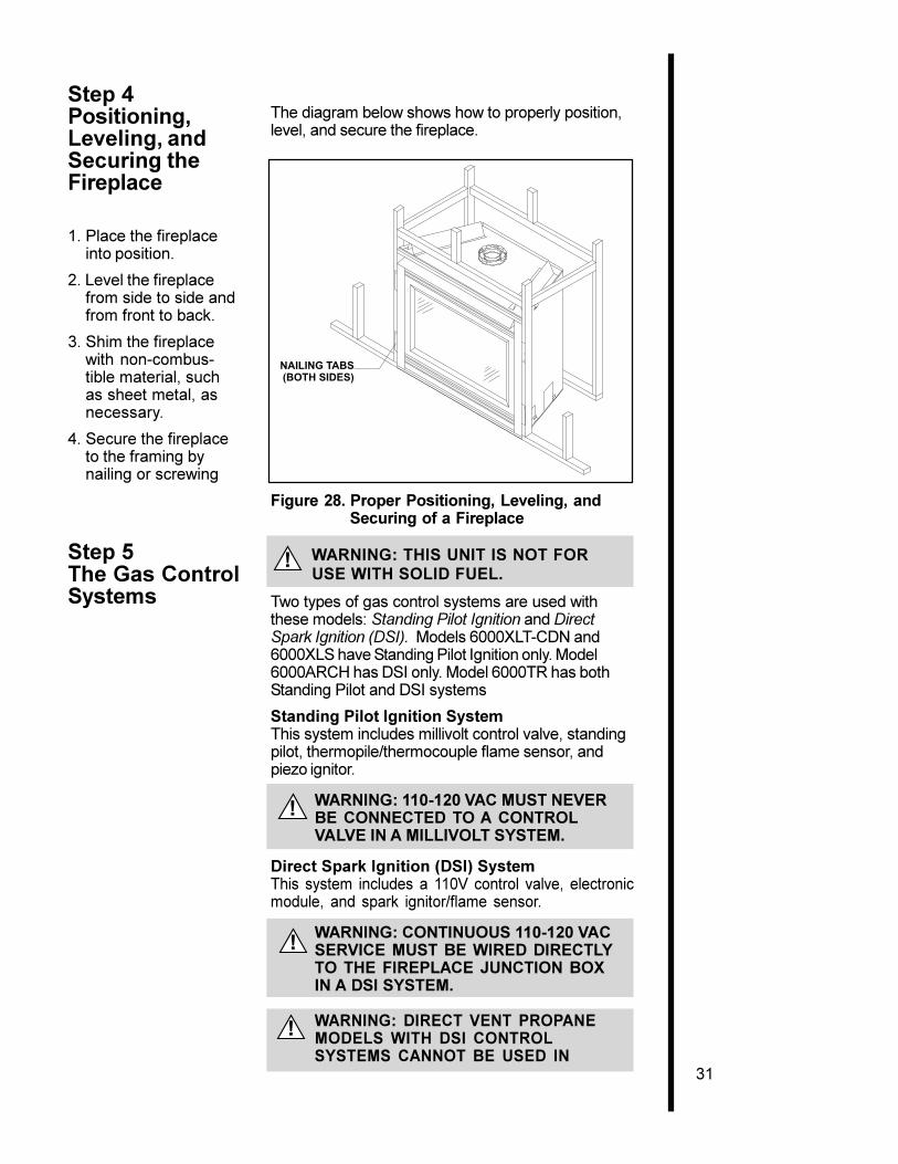
The diagram below shows how to properly position,level, and secure the fireplace.
1. Place the fireplaceinto position.
2. Level the fireplacefrom side to side andfrom front to back.
3. Shim the fireplacewith non-combus-tible material, suchas sheet metal, asnecessary.
4. Secure the fireplaceto the framing bynailing or screwing
Figure 28. Proper Positioning, Leveling, andSecuring of a Fireplace
Step 5The Gas ControlSystems
WARNING: THIS UNIT IS NOT FOR USE WITH SOLID FUEL.
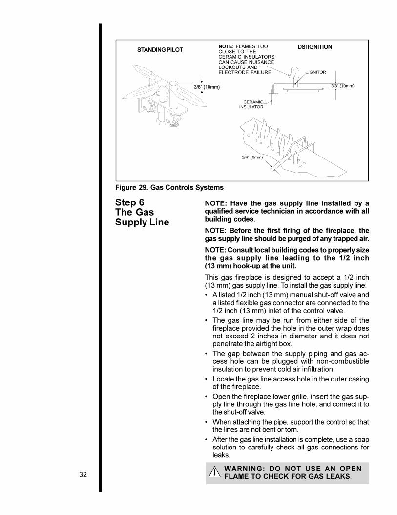
Two types of gas control systems are used withthese models: Standing Pilot Ignition and DirectSpark Ignition (DSI). Models 6000XLT-CDN and6000XLS have Standing Pilot Ignition only. Model6000ARCH has DSI only. Model 6000TR has bothStanding Pilot and DSI systems
Standing Pilot Ignition SystemThis system includes millivolt control valve, standingpilot, thermopile/thermocouple flame sensor, andpiezo ignitor.
WARNING: 110-120 VAC MUST NEVERBE CONNECTED TO A CONTROLVALVE IN A MILLIVOLT SYSTEM.
Direct Spark Ignition (DSI) SystemThis system includes a 110V control valve, electronicmodule, and spark ignitor/flame sensor.
WARNING: CONTINUOUS 110-120 VACSERVICE MUST BE WIRED DIRECTLYTO THE FIREPLACE JUNCTION BOXIN A DSI SYSTEM.
WARNING: DIRECT VENT PROPANEMODELS WITH DSI CONTROLSYSTEMS CANNOT BE USED IN
!
!
!
!
Step 4Positioning,Leveling, andSecuring theFireplace
32
STANDING PILOTNOTE: FLAMES TOOCLOSE TO THECERAMIC INSULATORSCAN CAUSE NUISANCELOCKOUTS ANDELECTRODE FAILURE.
DSI IGNITION
Figure 29. Gas Controls Systems
Step 6The GasSupply Line
NOTE: Have the gas supply line installed by aqualified service technician in accordance with allbuilding codes.
NOTE: Before the first firing of the fireplace, thegas supply line should be purged of any trapped air.
NOTE: Consult local building codes to properly sizethe gas supply line leading to the 1/2 inch(13 mm) hook-up at the unit.
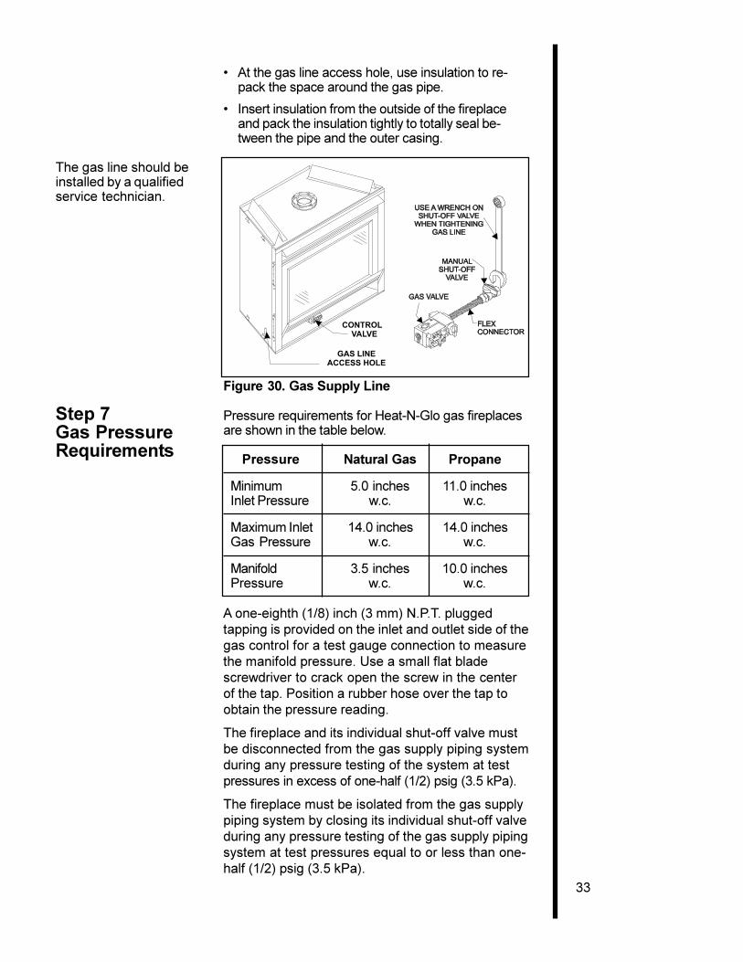
This gas fireplace is designed to accept a 1/2 inch(13 mm) gas supply line. To install the gas supply line:� A listed 1/2 inch (13 mm) manual shut-off valve and
a listed flexible gas connector are connected to the1/2 inch (13 mm) inlet of the control valve.
� The gas line may be run from either side of thefireplace provided the hole in the outer wrap doesnot exceed 2 inches in diameter and it does notpenetrate the airtight box.
� The gap between the supply piping and gas ac-cess hole can be plugged with non-combustibleinsulation to prevent cold air infiltration.
� Locate the gas line access hole in the outer casingof the fireplace.
� Open the fireplace lower grille, insert the gas sup-ply line through the gas line hole, and connect it tothe shut-off valve.
� When attaching the pipe, support the control so thatthe lines are not bent or torn.
� After the gas line installation is complete, use a soapsolution to carefully check all gas connections forleaks.
WARNING: DO NOT USE AN OPENFLAME TO CHECK FOR GAS LEAKS.!
1/4" (6mm)
IGNITOR
3/8” (10mm)
CERAMICINSULATOR
33
� At the gas line access hole, use insulation to re-pack the space around the gas pipe.
� Insert insulation from the outside of the fireplaceand pack the insulation tightly to totally seal be-tween the pipe and the outer casing.
The gas line should beinstalled by a qualifiedservice technician.
Figure 30. Gas Supply Line
Step 7Gas PressureRequirements
Pressure requirements for Heat-N-Glo gas fireplacesare shown in the table below.
Pressure Natural Gas Propane
Minimum 5.0 inches 11.0 inchesInlet Pressure w.c. w.c.
Maximum Inlet 14.0 inches 14.0 inchesGas Pressure w.c. w.c.
Manifold 3.5 inches 10.0 inchesPressure w.c. w.c.
A one-eighth (1/8) inch (3 mm) N.P.T. pluggedtapping is provided on the inlet and outlet side of thegas control for a test gauge connection to measurethe manifold pressure. Use a small flat bladescrewdriver to crack open the screw in the centerof the tap. Position a rubber hose over the tap toobtain the pressure reading.
The fireplace and its individual shut-off valve mustbe disconnected from the gas supply piping systemduring any pressure testing of the system at testpressures in excess of one-half (1/2) psig (3.5 kPa).
The fireplace must be isolated from the gas supplypiping system by closing its individual shut-off valveduring any pressure testing of the gas supply pipingsystem at test pressures equal to or less than one-half (1/2) psig (3.5 kPa).
CONTROLVALVE
GAS LINEACCESS HOLE
34
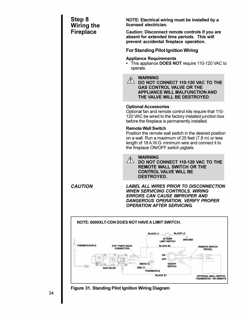
NOTE: 6000XLT-CDN DOES NOT HAVE A LIMIT SWITCH.
!
!
Figure 31. Standing Pilot Ignition Wiring Diagram
Step 8Wiring theFireplace
NOTE: Electrical wiring must be installed by alicensed electrician.
Caution: Disconnect remote controls if you areabsent for extended time periods. This willprevent accidental fireplace operation.
For Standing Pilot Ignition Wiring
Appliance Requirements� This appliance DOES NOT require 110-120 VAC to
operate.
WARNINGDO NOT CONNECT 110-120 VAC TO THEGAS CONTROL VALVE OR THEAPPLIANCE WILL MALFUNCTION ANDTHE VALVE WILL BE DESTROYED.
Optional AccessoriesOptional fan and remote control kits require that 110-120 VAC be wired to the factory installed junction boxbefore the fireplace is permanently installed.
Remote Wall SwitchPosition the remote wall switch in the desired positionon a wall. Run a maximum of 25 feet (7.8 m) or lesslength of 18 A.W.G. minimum wire and connect it tothe fireplace ON/OFF switch pigtails.
WARNINGDO NOT CONNECT 110-120 VAC TO THEREMOTE WALL SWITCH OR THECONTROL VALVE WILL BEDESTROYED.
CAUTION LABEL ALL WIRES PRIOR TO DISCONNECTIONWHEN SERVICING CONTROLS. WIRINGERRORS CAN CAUSE IMPROPER ANDDANGEROUS OPERATION. VERIFY PROPEROPERATION AFTER SERVICING.
35
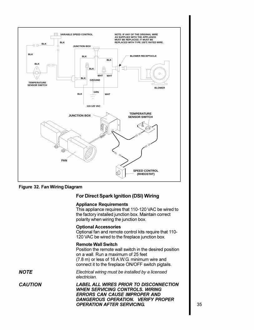
Figure 32. Fan Wiring Diagram
For Direct Spark Ignition (DSI) Wiring
Appliance RequirementsThis appliance requires that 110-120 VAC be wired tothe factory installed junction box. Maintain correctpolarity when wiring the junction box.
Optional AccessoriesOptional fan and remote control kits require that 110-120 VAC be wired to the fireplace junction box.
Remote Wall SwitchPosition the remote wall switch in the desired positionon a wall. Run a maximum of 25 feet(7.8 m) or less of 16 A.W.G. minimum wire andconnect it to the fireplace ON/OFF switch pigtails.
NOTE Electrical wiring must be installed by a licensedelectrician.
CAUTION LABEL ALL WIRES PRIOR TO DISCONNECTIONWHEN SERVICING CONTROLS. WIRINGERRORS CAN CAUSE IMPROPER ANDDANGEROUS OPERATION. VERIFY PROPEROPERATION AFTER SERVICING.
NOTE: IF ANY OF THE ORIGINAL WIREAS SUPPLIED WITH THE APPLIANCE MUST BE REPLACED, IT MUST BE REPLACED WITH TYPE 105 C RATED WIRE.O
JUNCTION BOX
VARIABLE SPEED CONTROL
TEMPERATURESENSOR SWITCH
WHT
GRN
BLK
BLK
110-120 VAC
BLOWER
BLOWER RECEPTACLEBLK
BLK
BLK
BLK
WHT
GROUND
WHT
BLK
BLK
BLK
FAN
TEMPERATURESENSOR SWITCH
SPEED CONTROL(RHEOSTAT)
JUNCTION BOX
36
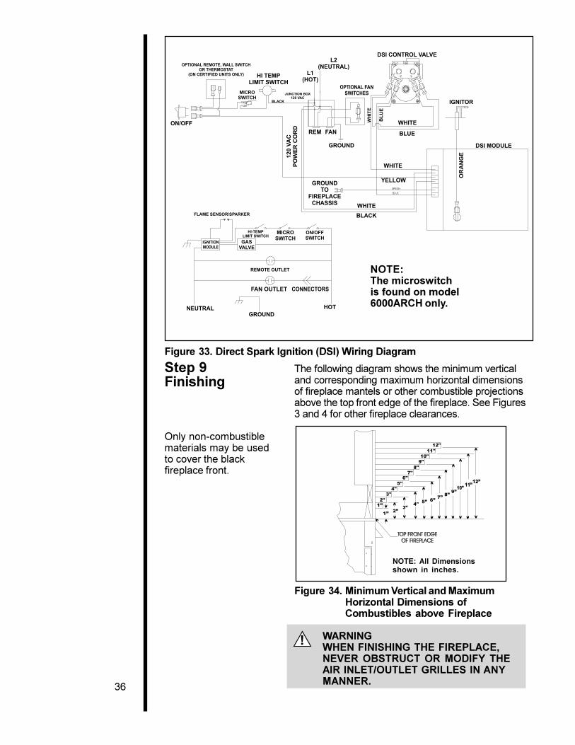
Figure 33. Direct Spark Ignition (DSI) Wiring Diagram
Step 9Finishing
The following diagram shows the minimum verticaland corresponding maximum horizontal dimensionsof fireplace mantels or other combustible projectionsabove the top front edge of the fireplace. See Figures3 and 4 for other fireplace clearances.
Only non-combustiblematerials may be usedto cover the blackfireplace front.
NOTE:The microswitchis found on model6000ARCH only.
NOTE: All Dimensionsshown in inches.
!
Figure 34. Minimum Vertical and MaximumHorizontal Dimensions ofCombustibles above Fireplace
WARNINGWHEN FINISHING THE FIREPLACE,NEVER OBSTRUCT OR MODIFY THEAIR INLET/OUTLET GRILLES IN ANYMANNER.
37
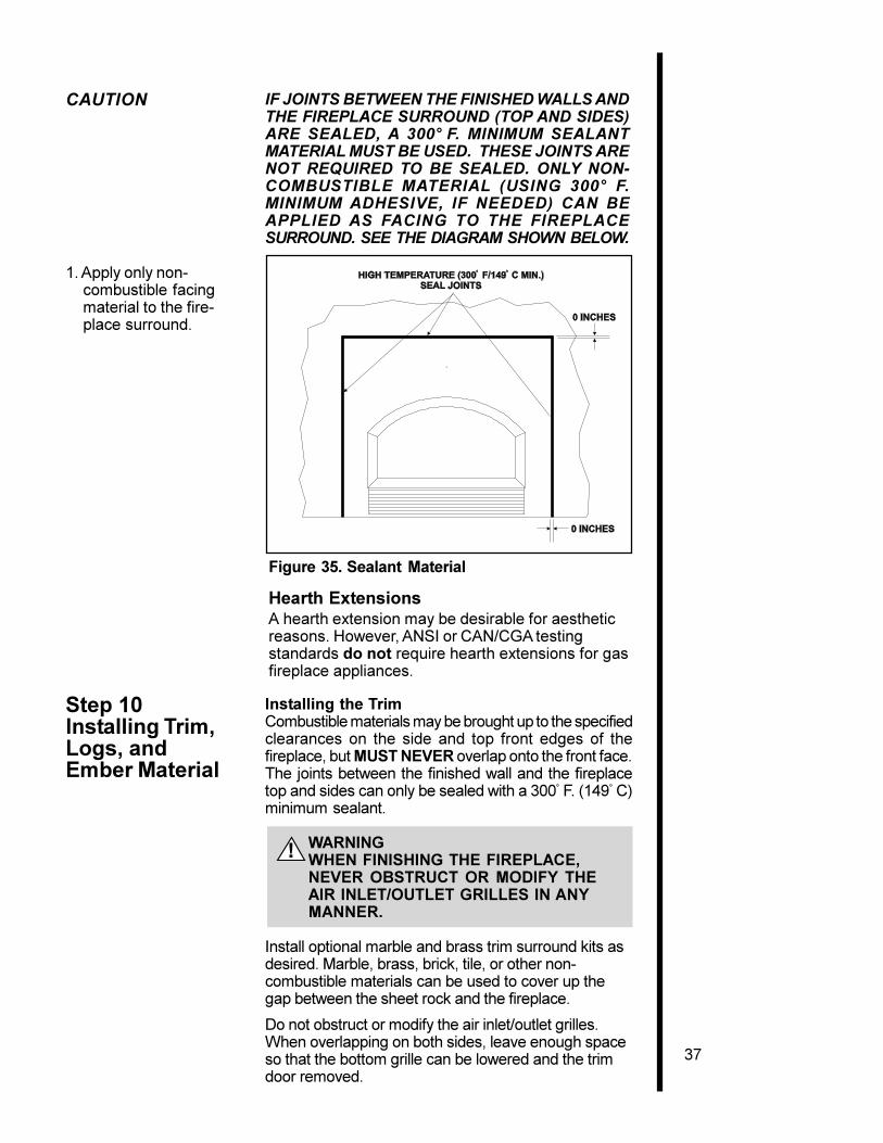
CAUTION IF JOINTS BETWEEN THE FINISHED WALLS ANDTHE FIREPLACE SURROUND (TOP AND SIDES)ARE SEALED, A 300° F. MINIMUM SEALANTMATERIAL MUST BE USED. THESE JOINTS ARENOT REQUIRED TO BE SEALED. ONLY NON-COMBUSTIBLE MATERIAL (USING 300° F.MINIMUM ADHESIVE, IF NEEDED) CAN BEAPPLIED AS FACING TO THE FIREPLACESURROUND. SEE THE DIAGRAM SHOWN BELOW.
1. Apply only non-combustible facingmaterial to the fire-place surround.
Installing the TrimCombustible materials may be brought up to the specifiedclearances on the side and top front edges of thefireplace, but MUST NEVER overlap onto the front face.The joints between the finished wall and the fireplacetop and sides can only be sealed with a 300° F. (149° C)minimum sealant.
WARNINGWHEN FINISHING THE FIREPLACE,NEVER OBSTRUCT OR MODIFY THEAIR INLET/OUTLET GRILLES IN ANYMANNER.
Install optional marble and brass trim surround kits asdesired. Marble, brass, brick, tile, or other non-combustible materials can be used to cover up thegap between the sheet rock and the fireplace.
Do not obstruct or modify the air inlet/outlet grilles.When overlapping on both sides, leave enough spaceso that the bottom grille can be lowered and the trimdoor removed.
!
Step 10Installing Trim,Logs, andEmber Material
Figure 35. Sealant Material
Hearth ExtensionsA hearth extension may be desirable for aestheticreasons. However, ANSI or CAN/CGA testingstandards do not require hearth extensions for gasfireplace appliances.
38
Positioning the LogsIf the gas logs have been factory installed theyshould not need to be positioned.
If the logs have been packaged separately, refer tothe installation instructions that accompany thelogs. Save the log instructions with thismanual.
If sooting occurs, the logs might need to berepositioned slightly to avoid excessive flameimpingement.
Placing the Ember Material
Two separate bags of ember material are shippedwith this gas fireplace:
� The bag labeled Golden Ember (GE-93) is flamecolorant material.
� The bag labeled Glowing Ember (050-721) isstandard glowing ember material.
To place the ember material:
� Turn the tension springs around the glass door 90°.
� Remove the glass door from the unit.
� NOTE: FOR MODEL 6000ARCH ONLY.Remove wing nuts and glass clips. Pull glass outfrom bottom and pull downward.
� Cover the top of the burner with a single layer ofember material. Then sprinkle GE-93 on top ofthe burner.
� Save the remaining ember materials for useduring fireplace servicing.
� Replace the glass door and a front trim door onthe unit (see Replacement Parts Section of themanual.)
� Pull out and twist the tension springs 90° to lock.
39
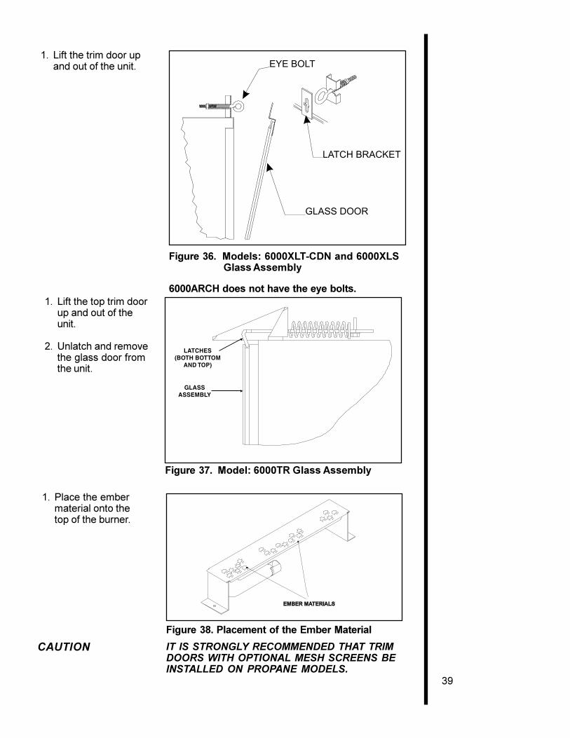
1. Lift the trim door upand out of the unit. EYE BOLT
LATCH BRACKET
GLASS DOOR
Figure 38. Placement of the Ember Material
CAUTION IT IS STRONGLY RECOMMENDED THAT TRIMDOORS WITH OPTIONAL MESH SCREENS BEINSTALLED ON PROPANE MODELS.
Figure 36. Models: 6000XLT-CDN and 6000XLS Glass Assembly
6000ARCH does not have the eye bolts.
1. Place the embermaterial onto thetop of the burner.
Figure 37. Model: 6000TR Glass Assembly
1. Lift the top trim doorup and out of theunit.
2. Unlatch and removethe glass door fromthe unit.
40
Before lighting the fireplace, be sure to do thefollowing:
Remove all paperwork and documents from thefireplace.
Review safety warnings and cautions
� Read the Safety and Warning Informationsection at the beginning of this Installers Guide.
Double-check for gas leaks
� Before lighting the fireplace, double-check the unitfor possible gas leaks.
Double-check vent terminations and frontgrilles for obstructions.
� Before lighting the fireplace, double-check the unitfor possible obstructions that could be blockingthe vent terminations or the front grilles.
Double-check for faulty components
� Any component that is found to be faulty MUSTBE replaced with an approved component.Tampering with the fireplace components isDANGEROUS and voids all warranties.
A small amount of air will be in the gas supply lines.When first lighting the fireplace, it will take a fewminutes for the lines to purge themselves of this air.Once the purging is complete, the fireplace will lightand will operate normally.
Subsequent lightings of the fireplace will not requirethis purging of air from the gas supply lines, unlessthe gas valve has been turned to the OFFposition, in which case the air would have to bepurged.
NOTE: The fireplace should be run for 8 hours onthe inital start-up.This will help to cure the chemicalsused in the paint and logs.
You�ve reviewed all safety warnings, you�ve checkedthe fireplace for gas leaks, you know the ventsystem is unobstructed, and you�ve checked forfaulty components. Now you�re ready to light thefireplace.
WARNINGPLEASE REFER TO THE USER�SMANUAL FOR ALL CAUTIONS, SAFETY,AND WARNING INFORMATIONPERTAINING TO THE LIGHTING ANDOPERATION OF THE FIREPLACE.
!
Step 11Before Lightingthe Fireplace
Step 12Lighting theFireplace
41
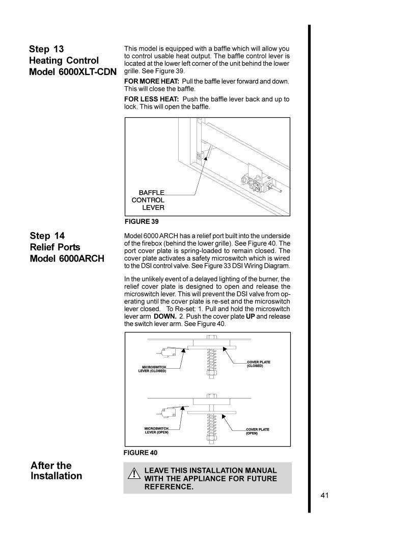
This model is equipped with a baffle which will allow youto control usable heat output. The baffle control lever islocated at the lower left corner of the unit behind the lowergrille. See Figure 39.
FOR MORE HEAT: Pull the baffle lever forward and down.This will close the baffle.
FOR LESS HEAT: Push the baffle lever back and up tolock. This will open the baffle.
FIGURE 39
After theInstallation
LEAVE THIS INSTALLATION MANUALWITH THE APPLIANCE FOR FUTUREREFERENCE.
Step 13Heating ControlModel 6000XLT-CDN
Step 14Relief PortsModel 6000ARCH
Model 6000 ARCH has a relief port built into the undersideof the firebox (behind the lower grille). See Figure 40. Theport cover plate is spring-loaded to remain closed. Thecover plate activates a safety microswitch which is wiredto the DSI control valve. See Figure 33 DSI Wiring Diagram.
In the unlikely event of a delayed lighting of the burner, therelief cover plate is designed to open and release themicroswitch lever. This will prevent the DSI valve from op-erating until the cover plate is re-set and the microswitchlever closed. To Re-set: 1. Pull and hold the microswitchlever arm DOWN. 2. Push the cover plate UP and releasethe switch lever arm. See Figure 40.
FIGURE 40
!
42
4MaintainingandServicingYourFireplace
FireplaceMaintenance
Although the frequency of your fireplace servicing andmaintenance will depend on use and the type ofinstallation, you should have a qualified servicetechnician perform an appliance check-up at thebeginning of each heating season. See the table belowfor specific guidelines regarding each fireplacemaintenance task.
IMPORTANT TURN OFF THE GAS BEFORE SERVICINGYOUR FIREPLACE.
Type ofFireplace Fireplace Maintenance Task To
Maintenance Frequency By Be Completed
Replacing Once annually, Qualified Brush away loose ember material nearOld Ember during the Service the burner. Replace old emberMaterial annual check-up Technician material with new dime-size and -shape
pieces of Golden Ember (GE-93) andGlowing Ember (050-721). New embermaterial should be placed alternately ontop of the burner�a layer of GoldenEmber, a layer of Glowing Ember,and so on. Save the remaining embermaterial and repeat this procedure atyour next servicing. For moreinformation, see Placing EmberMaterial in the INSTALLERS GUIDE.
Cleaning Once annually Qualified Brush or vacuum the controlBurner Service compartment, fireplace logs, and& Controls Technician burner areas surrounding the logs.
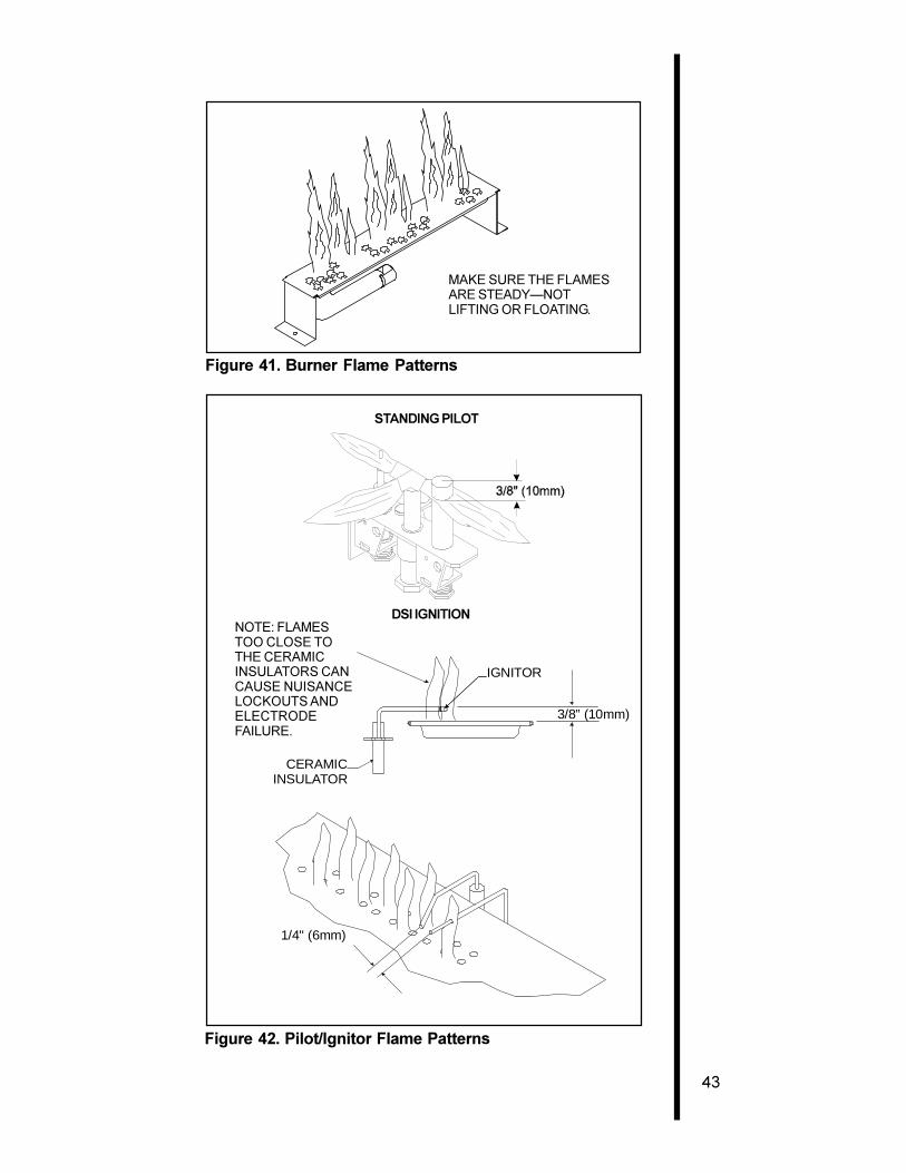
Checking Periodically Qualified Make a visual check of your fireplace�sFlame Service flame patterns. Make sure the flamesPatterns, Technician/ are steady�not lifting or floating. SeeFlame Height Owner the picture in Figure 41. The flame
sensor(DSI) or thermopile/thermocouple(standing pilot) tips should be coveredwith flame. See the picture in Figure 42.
Checking Before initial use Qualified Inspect the external vent cap on aVent System and at least Service regular basis to ensure that no debris is
annually thereafter, Technician/ interfering with the flow of air. Inspectmore frequently Owner entire vent system for proper function.if possible
Cleaning As necessary Homeowner Clean as necessary, particularly afterGlass Door adding new ember (flame colorant)
material. Film deposits on the inside ofthe glass door should be cleaned offusing a household glass cleaner.NOTE: DO NOT handle or attempt toclean the door when it is hot andDO NOT use abrasive cleaners.
43
STANDING PILOT
Figure 41. Burner Flame Patterns
MAKE SURE THE FLAMESARE STEADY�NOTLIFTING OR FLOATING.
Figure 42. Pilot/Ignitor Flame Patterns
DSI IGNITIONNOTE: FLAMESTOO CLOSE TOTHE CERAMICINSULATORS CANCAUSE NUISANCELOCKOUTS ANDELECTRODEFAILURE.
1/4" (6mm)
IGNITOR
3/8” (10mm)
CERAMICINSULATOR