Embed Size (px)
Citation preview

CAPILLARY PUMP LOOP (CPL)
HEAT PIPE
DEVELOPMENT STATUS REPORT
August 1982
Prepared for National Aeronautics and Space Administrat ion
Goddard Space F l i g h t Center Greenbelt, M ~ r y l and 20771
I n Response t o Contract NAS5-26660, Task 005
Prepared by OAO Corporation
7500 Greenway Center Greenbelt, Maryland 20770
https://ntrs.nasa.gov/search.jsp?R=19850009014 2019-04-18T18:35:32+00:00Z

CONTENTS
Sect ion . Pase
1 . INTRODUCTION . . . . . . . . . . . . . . . . . . . . . . . . . . 1-1 2 . CPL HEAT PIPE OPERATING PRINCIPLE . . . . . . . . . . . . . . . 2-1
3 . 9ROTOTYPE DESIGK . . . . . . . . . . . . . . . . . . . . . . . . 3-1
3.1 Design Sumnary . . . . . . . . . . . . . . . . . . . . . . 3-3
3.2 Evaporator Design . . . . . . . . . . . . . . . . . . . . . 3-7
. . . . . . . . . . . . . . . . . . . . . 3.3 Condenser Design 3-7
. . . . . . . . . . . . . . . . 3.4 L i q u i d Inventory Management 3-7
. . . . . . . . . . . . . . . . . . . . 3.5 Temperature Control 3-11
. . . . . . . . . . . . . . . . 3.6 Pressure Priming . . . . 3-12
3.7 Non-Condensible Gas Trap . . . . . . . . . . . . . . . . . 3-13
4 . PROOF-OF-CONCEPT TESTS . . . . . . . . . . . . . . . . . . . . . 4-1
4.1 Test Set.Up . . . . . . . . . . . . . . . . . . . . . . . . 4-1
4.2 Heat Transport Performance . . . . . . . . . . . . . . . . 4-3
4.3 Heat Transfer Performance . . . . . . . . . . . . . . . . . 4-6
. . . . . . . . . . . . . . . . . . . . . 4.4 Pressure Priming 4-7
. . . . . . . . . . . . . . . . . . . . 4.5 Temperature Coctrc l 4-10
. . . . . . . . . . . . . . . . . . . . . 4.6 Heat Load Sharing 4-10
5 SUMMARY AND CONCLUSIONS . . . . . . . . . . . . . . . . . . . . 5-1
REFERENCES . . . . . . . . . . . . . . . . . . . . . . . . . . . . . REF-1
ILLUSTRATIGNS
F i gure Page
. . . . . . . . . . . . . . . . . 2-1 Cap i l l a r y Pump Loop Schematic 2-2
. . . . . . . . . . . . . . . . . . . . 3-1 CPL Heat Pipe Prototype 3-2
. . . . . . . . . . . . . . . . . . . 3-2 Cap i l l a r y Pump Evaporator 3-8
. . . . . . . . . . . . . . . . . 3-3 L i q u i d Inventory D i s t r i b u t i o n 3-10
. . . . . . . . . . . . . . . . . . . 3-4 Wn-Condensi b l e Gas Trap 3-15
. . . . . . . . . . . . . . . . . . . 4-1 CPL Heat Pipe Test Set.Up 4-2
. . . . . . . . . . . . . . . . . . 4-2 Typical Reccvery Under Load 4-8
. . . . . . . . . . . . . . . . . . . 4-3 Temperature Cycle P r o f i l e 4-11
CONTENTS ( con t . )
ILLUSTRATIONS (cont .)
F i gure Page
. . . . . . . . . . . . . . . . 4-4 Heat Load Sharing Test Profile 4-12
TABLES
Table - Page
. . . . . . . . . . . . 3-1 CPL Heat Pipe Prototype Design Surmary 3-4 . . . . . . . 3-2 CPL Heat Pipe Prototype Theoretical Performance. 3-6
. . . . . . . . . 4-1 CPL Heat Pipe Prototype Performance Siqmary. 4-4 . . . . . . . . 5-1 CPL Heat P'pe Development Status-February 1982 5-2
iii
2,- w-,

SECTION 1. INTRODUCTION
A significant ~dvance in heat pipe technology has recently been realized by the re-introduction of the Capi lary ?ump Loop (CPL) concept as a potential candidate for the management of large heat loads. The CPL heat pipe, f i r s t developed by NASA/Lewis i n the mic 1960's (Reference I ) , i s a two-phase heat transfer device capable of transferring heat e f f i c i en t l y , with l i t t l e temperature di f ferent i a1 and no external power (pump) requirements. I t offers 1 arge heat load carrying capacities together with substanti a1 nicking height in gravity. I t is currently being evaluated fo r potential application i n the thermal management of large space structures (Reference
2 1
Experimental lmps tested by NASA/Lewis in the mid 1960's demonstrated the f ea s ib i l i t y , the potential high heat load capacity and low gravity sensi- t i v i t y of the CPL heat pipe concept. Recently, a CPL heat pipe prototype was developed and tested f o r NASA/GSFC to demofistrate the p rac t ica l i ty of such a design including the f ea s ib i l i t y of multiple parall e l evaporator/ condenser zones within a single loop, heat load sharing between evaporators, 1 iquid inventory/temperature control feature, priming under load and entrapment of non-condensi ble gases. The design a1 so i ncorpor- ates very lzng yapor and l iquid return headers (approximately 32 f ee t ) designed t o demonstrate the abi 1 i t y of transferring heat loads over a large distance.
The primary objectives of development and t e s t e f fo r t s conducted t o date were to establish f ea s ib i l i t y of the CPL heat pipe design. The scope of these e f for t s were 1 imited and the CPL heat pipe prototype was designed and fabricated using comnerci a l l y available hardware and materi a l s . The scope of the t e s t e f fo r t s wers also limited t o proof-of-concept test ing. Despite these 1 ini t a t i ons, sign if i cant progress has been nade i n the development of the CPL heat pipe. The curreot development s ta tus of the CPL heat pipe
i s presented i n the section tha t follows.

SECTION 2. CPL HEAT PIPE OPERATING PRINCIPLE
The basic design of the CPL heat pipe, i l l u s t r a t e d schematically i n Figure
2-1, consists of an evaporator, which includes a wick structure, and a
continuous loop which i s devoid o f any wick material. The loop, which can
be made o f smooth wall tubing, provi des a f low passage f o r the vapor, heat
t ransfer area i n the condenser and l i q u i d re turn t o the evaporator.
The CPL heat pipe i s a continuous loop i n which both tne vapor and l i q u i d
always f low i n the same direct ion. As heat i s appl ied t a the evaporator,
l i q u i d evaporates from the saturated wick and flows through the loop t o the
condenser zone where heat i s removed. Flow i n the condenser zone i ni ti a1 l y
consists o f high-vel oci t y vapor plus 1 i qu i d wall f i l m which subsequently
turns i n t o l i q u i d "s lug f low". The l i q u i d i s returned t o the evaporator
v i a a subcooled 1 iqu i d re turn header w9ich collapses any rsnai n i ng vapor
bubbles. The uniqueness of the CPL heat pipe i s tha t a wick structure i s
required i n the evaporator zone only. Capi 11 ary ac t i on i s 1 i m i ted t o tha t
zone, where i t provides the necessary pressure d i i f o r e n t i a1 t o i n i t i a t e
vapor flow. i n the remainder of the loop, pressure gxerted by the f low o f
vapor on the 1 i quid col unn ahead of i t drives the 1 i qui 4 back t o the
evaporator by a posi ti ve "p i ston" ac t i on.


SECTION 3. PROTOTYPE DESIGV
The design of the CPL heat pipe, i l lustrated in Figure 3-1, differs significantly from the early NASAILewis capillary pumped loop. The major differences include:
a. Paral 1 el Evaporators and Condensers. Paral 1 el ci rcui t s are
essenti a1 to m i nimi ze pressure drops; to accomnodate mu1 t i pl e heat sources and heat sinks; and to f a c i l i t a t e the design and construction of cold plates. Pressure drop consi derati ons are especi a1 l y cr i t i cal because of the 1 imi ted pumpi ng head that can be developed by capi 11 ary acti on.
b. Reservoir. A reservoir has been included as an integral part of the CPL heat pipe design. I t s primary function i s liquid inventory control. Addi t i onal features derived from the use of the reservoir i ncl ude tcvperature control; pressure primi ng under load and/or against gravity; and reduced s e ~ s i t i v i t y t o f luid 1 eaks .
c. Non-Condensi ble Gas ( N C G ) Trap. A we1 1 established weakness of high composite capillary systems (such as the CPL heat pipe), i s their sensit ivity t o the presence of non-condensi bl e gases. The one-way action of the capillary punped loop and the physical separation of the vapor and 1 iquid flow channels a1 lows the introduction of a trap to prevent the displacement of non- condensi bl e gases i nto the evaporator zones.
Other features incorporated i nto the CPL heat pipe design i ncl ude separate sizing of the vapor header and 1 iquid return channel s t o optimize pressure drops; and the use of axi ally grooved tubing in the condenser to enhance heat transfer .

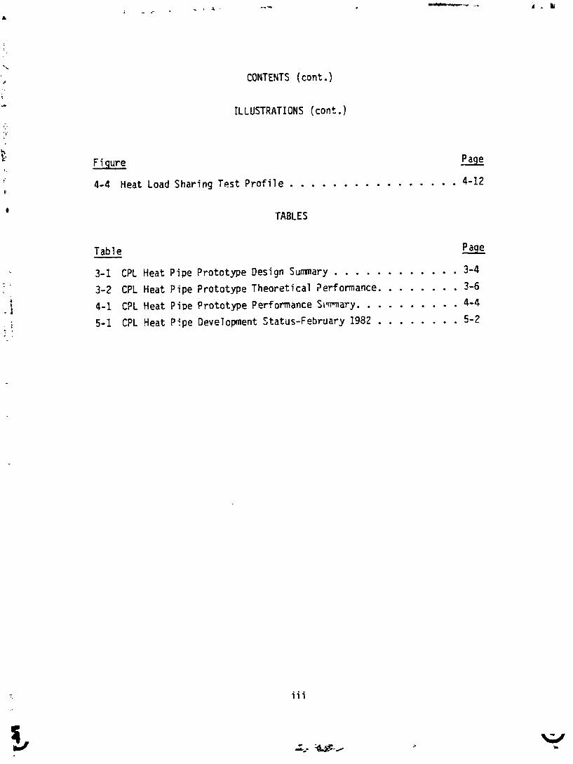
3.1 DESIGN SUMMARY
A CPL heat p ipe prototype (Figure 3-1) cons is t ing o f two para l l e l c a p i l l ary
pump evaporators and two para l l e l a x i a l 1 y grooved condensers was developed
for proof-of-concept tes t ing . The evaporator zone and condenser zone are
interconnected by a 1/2 in. diameter X 0.035 in . wal l vapor header and a
1/4 in. diameter X 0.035 in . wa l l l i q u i d re turn . Both the vapor header and
the l i q u i d r e t u r n are made of smooth wal led aluminum tub ing bent i n t o
several passes t o prov ide an adiabat ic t ransport length o f 9.8 meters (32
feet) . The CPL heat p ipe prototype design a1 so includes a 100 cc capaci ty
non-condensible gas t rap located a t the o u t l e t c f the condenser tone and a
1000 cc capaci ty l i q u i d reservo i r (accumulator) connected t o the evapora-
t o r s as shgwn i n F igure 3-1. A l l tub ing connections were made w i th s ta in -
1 ess steel compression f i t t i n g s .
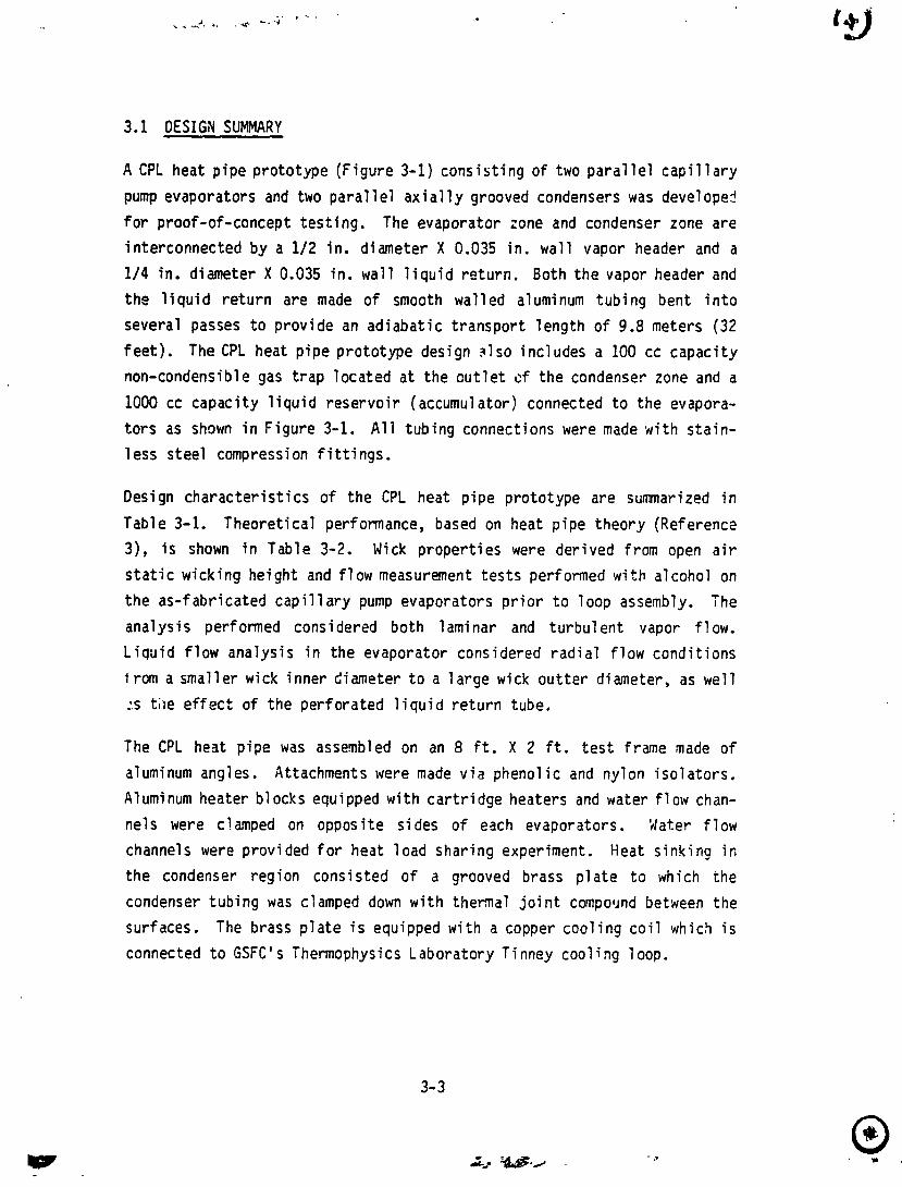
Design cha rac te r i s t i cs of the CPL heat p ipe prototype are summarized i n
Tab1 e 3-1. Theoret ica l performance, based on heat p ipe theory (Ref erencs
3), i s shown i n Table 3-2. Wick proper t ies were derived from open a i r
s t a t i c wick ing height and flow measurement t es t s performed wi th alcohol on
the as-f abricated c a p i l l a r y pump evaporators p r i o r t o loop assembly. The
analysis performed considered both laminar and tu rbu len t vapor f l ow.
L i q u i d f low analysis i n the evaporator considered r a d i a l f l o w condi t ions
from a smaller wick inner diameter t o a l a rge wick ou t te r diameter, as wel l
2s t i le e f fec t o f the per forated l i q u i d r e t u r n tube.
The CPL heat p ipe was assembled on an 8 ft. X 2 ft. t e s t frame made o f
aluminum angles. Attachments were made v i a phenol ic and nylon i so la to rs .
Aluminum heater blocks equipped w i th ca r t r i dge heaters and water f l ow chan-
nels were clamped on opposite sides o f each evaporators. 'dater f l ow
channels were provided f o r heat load sharing experiment. Heat s ink inp i n
the condenser region consisted o f a grooved brass p l a t e t o which the
condenser tub ing was clamped down w i t h thermal j o i n t C O ~ ~ O I J ~ ~ between the
surfaces. The brass p l a t e i s equipped w i th a copper coo l ing c o i l which i s
connected t o GSFC' s Thermophysics Laboratory T i nney cool: ng 1 oop.
Table 3-1. CPL Heat Pipe Prototype Design Sumnary
Evaporators - r Number o f Evapora t~ rs i n Para1 l e l 2
e Total Length 0.38 m (15 in.)
r Act ive Length 0.31 m (12 in.)
Condensers
r Number o f Condensers i n P a r a l l e l 2
r Maximum Act ive Length Per 1.8 m (72 in . ) Condenser
r Subcooled Section Length 0.61 m (27 in.)
Wick - r Mater ia l Alumina/Si 1 i c a F e l t
Mean F iber Diameter 2.5 Micron
r Packing Density 40%
r E f f e c t i v e Pumping Radius 9.7 Micron (Measured )
r Permeabi 1 i ty (Measured) 2.6 X 10- 13 ,2
r Geometry See Figure 3-2
Evaporator Tube
e Mater ia l
e Permeabi 1 i t y
e Flow Area
e Geometry
Vapor Header
r Mater ia l
r Inner Diameter
e length
~ l u m . A x i a l l y Gror ved Tubing 8 2 4.57 X 10' m
-5 2 6 . 9 X 1 0 m
Tag 54-5 (See Figure 3-2)
Alum. Smooth Walled Tubing
1.1 X m (0.43 in.)
9.8 m (386 in.)

Table 3-1. CPL Heat Pipe Prototype Design Sumnary (cont . )
L i q u i d Return
0 M a t e r i a l
a Inner Diameter
0 Length
Condenser
a M a t e r i a l
a Vapor Diameter
Alum. Smooth Walled Tubing
4.6 X m (.I8 i n . )
9.8 m (386 i n . )
Alum. A x i a l l y Grooved Tubing
4.' X rn (0.185 in.)

Tab1 e 3-2. CPL Heat Pipe Prototype Theoret ical Performance
Vorking Flu1 1 Freon-11
Operating Temperature 20°c
Ac t ive 1 ength Per Condenser* 0.5 m (20 in.)
Capi 11 ary Pumping Head 3940 n/m2
Maximum Heat Transport (Zero Elevat ion; 400 Watts
Maximum S t a t i c Wicking Height 0.27 m (10.5 in . )
Pressure Drop D i s t r i b u t i o n
r Wick
r Vapor - Evaporator
e Vapor - Header
Vapor - Condenser
r L i q u i d - Condenser
e L i q u i d - Return L ine
r L i q u i d - Evaporator
* Based on obse rv~d temperature p r o f i 1 e w i t h the co ld p l a t e temperature a t
approximately - 3 ' ~

EVAPORATOR UES I GN
Construct i on o f the capi 11 ary pump evaporators, i 11 ustrated i n F igure 3-2,
consisted o f 1.15 i n . Tag 54-5 a x i a l l y grooved a lm inun tub ing packed w i t h
a luninum/s i l ica f i b e r wick. The wick was made by c u t t i n g washers from 1 i n . t h i c k f e l t t ha t was inser ted ar,d packed i n t o the Tag 54-5 tub ing t o an
approximate densi ty o f 40 percent. Approximate1 y 140 washers were
inser ted i n t o each of the c a p i l l a r y punp evaporators. Located i n t he
center of the wick i s a 3/8 i n . diameter perforated l i q u i d r e t u r n w i t h a
1/4 in. diameter reservoi r i n j e c t o r tube located i n s ~ d e the 3 /8 i n . l i q u i d
return. The compacted wick mater ia l i s reta ined by an aluninum r e t a i n e r
f i t t i n g a t the vapor o u t l e t end snd a press f i t t e d a1 uminlsl washer a t t he
1 i quid re turn end. 'clel ded a1 uni nun end f i t t i n g s complete che assenbly o f
the capi 11 ary pump evaporator.
CONDENSER DESIGY
Axi a1 l y grooved tubing was used i n the design o f the condensers t o erlhance
heat t rans fer chzrac ter is t i cs . The condenser zone consis ts of two 1.8
metsrs (6 f t . ) p a r a l l e l paths and a 0.6 meters ( 2 f t . ) subcooled zone.
3.4 LIQUID INVENTORY MANAGEMEaT
Stable operation o f the CPL heat pipe requi res complete condensation o f the
vapor phase before the working f l u i d e n t m the evaporator zone. I n
addit ion, l i q u i d en ter ing the evaporator must Se a t a temperature lower
than saturat ion. This i s because a f i n i t e amount of heat, conducted
through the l i q u i d re tu rn end f i t t i n g , would cause vapor bubbles t o be
generated i n a saturated l i q u i d . Since these vapor bubbles cannot pass
through the wick st ructure, they wculd accumulated w i t h i n the l i q u i d
re turn l i n e u n t i l the resu l t i ng blockage would deprime the wick. To avoid
the above condit ions, a po r t i on o f the c~ndenser must be a1 located as a
subcooled region. This can be accomplished by charging t h e CPL heat pipe
w i t h s u f f i c i e n t ! i q u i d t o ensure a p a r t i a l l y blocked condenser a t a l l


times. Predetermined charging of the CPL heat pipe, however, presents several problems which include the fo l l owing:
a. Precise fluid inventory calculations and accurate charging procedures that would be required since condenser zone volume i s small compared to total volume. That i s , even small variances i n
total inventory will significantly affect extent of condenser blockage.
b. Liquid entrapment in the vapor header can significantly affect condenser zone blockage. The amount of entrapment, if any, cannot be predetermined.
c . If a non-condensi ble gas ( K G ! tr;p i s used in the systen design, liquid inventory will be displaced as NCG's are collected. Additional blockage of the condenser by the displaced 1 i qu i j wi 11 cause a performance degradation.
d. Fluid densities vary as a function of temperature. A CPL heat pipe charged to have a partially blocked condenser at low operating temperatures could be completely blocked at high
operating temperatures. The operating temperature of a CPL heat pipe with a fixed charge would be limited depending on the relative volume of the condenser zone as compared to the remainder of the system.
To avoid the above problems, a reservoir (accumulator) has been I ncorpor- ated as part of the CPL heat pipe design. As i l lustrated schematically i n
Figure 3-3, distribution of the : iquid between the reservoir and the loop is mai ctai ned by a pressure bal ance between the saturation pressure in the reservoir and the saturation pressure in the loop. Any change in loo? operating temperature due to vari ati ons in condenser Sl ockage caused by
the above factors or variations in heat load and/or sink temperature wi 1 1
cause a pressure imbalance which will result i n a d~splacement of liquid into or out of the reservoir. Condenser blockage i s thus increased or decreased until equilibrium i s restored.

In effect, tbe reservoir saturation conditions will control the loop saturation conditions as long as:
a. The reservoir i s of sufficient volune to accomodate the range of liquid displacement required to ~nai ntain variations in operating condi t i ons .
b. The reservoir i s only parti a1 l y f i l led under a1 1 conditions.
c. A parti a1 ly blocked condenser i s maintained a t a1 1 times.
To sa t i s fy the l a s t condition, the reservoir must be maintained a t a temperature which i s equal to or greater than the temperature at which liquid displacement from the subcooled regicn will occur. Any lower reservoir temperature will drain an excessive mount of iiquid from the loop to a point where subcooling conditions are no longer sat isf ied and the CPL heat pipe will deprime. A1 though the reservoir can be operated at any range of temperature, a single se t point designed to accom,odate maximum heat 1 oad/maximun si nk condi t i on will sat isfy a1 1 other operati ng conditions. Thus, a simple controller will sa t i scy CPL heat pipe reservoir rrqui rement s . 3.5 TEWE,RATIIRE CONTROL
The need to maintain temperature control of the reservoir i s predicated by the need to control liquid inventory in the CPL heat pipe for reasons previously discussed. A 1 though a temperature control led reservoir auds ccnrtqlexity to the C?L heat pipe design, the benefits derived f a r o u t ~ e i g h t
the disadlldntages. In addition to the abil i t y to compensate for any nunber of va! .: ~ b l e s in the ccjntrol of liquid inventory, a temperature controlled re. . rvoir provides the f 01 1 owing addi t i onal benefits:
a. Operating temperature of the CPL heat pipe i s control led by the se t point of the reservoir. Temperatures of components mounted on the CPL heat pipe are automati cal ly mai ntai ned over the enti re ,-ange of operating conditions.
b. Complete shut-down o f the CPL heat p ipe can be achieved.
Component temperature w i l l be maintained as lung as su f f i c i en t
power i s ava i l ab le t o compensate f o r p a r a s i t i c heat leaks.
c. Automatic shut-down o f the condenser under condi t ions where heat
load sharing between components i s requi red.
The temperature cont ro l fea ture i s derived from a pressure balance t h a t
must be maintained betueen t h e sa tura t ion pressure i n t h e rese rvo i r and t h e
sa tura t ion pressure i n t he loop. As stated e a r l i e r , any change i n l cop
temperature due t o var ia t ions i n heat load and/or s ink te ipe ra tu re w i l l
cause a pressure imbalance which w i 1 l r e s u l t i n a displacement of 1 i q u i d
in to , o r ou t of t h e reservo i r . Condenser blockage i s thus increased c r
decreased u n t i l equi1 i b r i m i s restored. Control o f the rese rvo i r
temperature a s t m a t i c a l l j cont ro ls t he vapor temperature i t h e CPL heat
pipe. The CPL heat p ipe thus operates 1 i ke a va r iab le conductance heat
p ipe w i t h the except ion t h a t l i q u i d blockage, instead o f non-condensi b l e
gas blockage, i s vsed t o vary the ac t i ve 1 ength o f the condenser.
The f a c t t h a t sa tura t ion pressure bal ance must be rnai n t a i ned a1 so provides
the a b i l i t y fo r complete shut-down o f the loop and heat load sharing
between components. If power from components i s not s u f f i c i ent t o mai n t a i n
sa tura t ion condit ions, complete f l o o d i n g o f the loop o r t o t a l deplet ion o f
t he reservo i r inventory (depending on r e l a t i v e vo lmes ) w i l l r esu l t . I n
e i t he r case, shut-Gown o f the CPL heat pipe i s achieved. S im i l a r l y , i f
heat sharing i s requi red between components, p a r t i a l or complete shut-down
o f the condenser w i l l occur i n order t o mainta in sa tura t ion pr, P ~ ~ ~ r ~
balance. The l i m i t i n g f a c t o r i n load sharing i s t he need t o mainta in
subcooled i n l e t condit ions i n t o the ac t ive evaporators.
3.6 PRESSURE PRIMING
A heated rese rvo i r provides the a b i l i ty t o prime the CPL heat pipe under
load and/or against g rav i ty . Pr iming can be achieved by r a i s i n g t h e
rese rvo i r temperature t o develop s u f f i c i e n t pressure t o a1 low d i s? l aczment
o f 1 i qui d i nto the evaporators.

In a typical dry-out of the CPL heat pipe, either thermal or mechanical, depletion of the liquid inventory in the evaporators causes a total
blockage of the condenser zone which extends into the vapor header. By maintaining the vapor header temperature a t higher than evaporztor dry-out temperature, and by cycl ing the reservoir to a temperature above the dry- out temperature, pressure priming of the evaporators can be achieved. Two factors make th i s priming mechanism possible: 1) the high saturation pressure established in a heated vapor header which allows liquid to be injected into the evaporators as i f the evaporators were subcooled and 2 ) complete shut-down of the loop by virtue of the blocked condenser zone which allows priming under an ar t i f ic ia l "no-load" cordition. Priming under load i s t h u s possible as long as the rate of evaporator temperature r i se under the dry-out condition i s sufficiently slow to allow the tmpera- ture cycling of the reservoir before the dry-out temperature exceeds vapor header temperature and/or before physical damage of the loop and the components mounted to the loop. P.lso, heat mus t be applied to the vapor header to maintain an elsvated temperature in that zone. The power level required can be minimal as long as the vapor header i s well insulated. During normal operation, power applied to the vapor header helps prevent liquid entrapment. The need to maintain power on the vapor header can be eliminated for pressure priming purposes with a reservoir f luid inventory capable of flooding the ent i re loop.
3.7 YON-CONDENSIBLE GAS TRAP
Any of the non-condensible gases in the CPL heat pipe will be swept along in the flow stream of the working fluid. Since they cannot be condensed, they begin forming small bubbles in the condenser. Eventually the bubbles w i l l migrate into the evaporators where surface tension forces a t the wick interface will prevent further migration. If sufficient quantities of non-condensible gases are present i n the system, accumulation of bubbles in the evaporators will continue until the CPL heat pipe deprimes.
To ensure reliable CPL heat pipe operation, non-condensibl e gases must be
reduced to sufficiently low quantities or they must be trapped in an area where they wi 11 not detrimental1 y affect performance. Past experience

with conventional heat pipes has demonstrated the impracticality of producing gas free heat pipes. The problem i s compounded in the CPL heat p ipe due t o extremely long tubing lengths and t ight ly packed wick structure which makes it impracticle to properly evaluate the systea prior t o charging. In addition, reflux boiler methods of gas separaticn used in conventional heat pipe processing cannot easily be applied to the CPL heat pipe due to i t s complex geometry and because gases tend to collect in the evaporator (instead of the condenser) where they cannot easily be removed.
Far these reasons a nun-condensible gas trag was introduced into the de~ ign of the CPL heat pipe. The gas trap i s located a t the exit of the condenser and i s designed (Figure 3-4) to separate gas bubbles from the liquid by
means of buoyancy forces exerted on the gas bubbles. T h i s design was selected fo r i t s simplicity and ease of implementation.
In zero-g operation, a mechanism other than buoyancy w i l l be required t o separate non-condensible gases from the liquid. One approach will be to use a gas trap design which incorporates a wick structure desi~ned t o
prevent further migration of gas bubbles by surface tensian forces at the wick interface.

GZAV ITY
S I R E YSH SC?EE!t COVERING
Figure 2-4. Non-Condensi ble Gas Trap.

SECTION 4. PROOF-OF-CONCEPT TEST
CPL heat p i pe proof -of -concept t e s t s have been conducted on several
occasions dur ing t he past 10 months. Tes t i ng was 1 i m i t ed i n scope and
design p r i m a r i l y t o e s t a b l i s h f e a s i b i l i t y o f design, t o o b t a i n an under-
s tanding of opera t ing behavior and t o e s t a b l i s h bas ic performance
c h a r a c t e r i s t i c s . Resu l ts of t e s t s conducted on t h r e e separate occasions
are sumnarized be1 ow.
4.1 TEST SET-UP
P r i o r t o t es t i ng , t he CPL heat p i pe was b r i e f l y evacuated w i t h a mechanical
pump and charged w i t h comnerci a l l y a v a i l ab le Freon-11. No speci a1 attempt
was made t o minimize non-condens i b l e gases.
The CPL t e s t set-up (F igure 5-1 ) i nc luded i n d i v i d u a l con t ro l o f evaporator
power t o e s t a b l i s h t h e a b i l i t y o f opera t ing p a r a l l e l c i r c u i t s a t d i f f e r e n t
power l eve l s . P rov i s i ons were a lso made t o cool t he evaporators t o
e s t a b l i s h the f e a s i b i l i t y o f heat load sharing. The set-up a l so inc luded a
vapor header heater designed t o prevent l i q u i d entrapment and t o p rov ide a
back pressure dur ing pr iming, and a r e s e r v o i r heater f o r temperature
con t ro l and pressure p r im ing cycles. A t t he condenser end, t he p a r a l l e l
condenser tubes were clamped t o a c o l d p l a t e connected t o t he GSFC Themo-
physics Laboratory Tinney cool ant loop. The e n t i r e I oop was i nsu la ted w i t h
f i b e r g l a s s i n s u l a t i o n b lanke ts w i t h the except ion o f the c o l d p l a t e which
was l e f t un- insul ated t o o b t a i n v i s u a l observat ion o f the l i qu id / vapo r
i n t e r f a c e 1 ocat ion i n t he condenser. V isual observat ions were made
poss ib l e by ma in ta in ing the co ld p l a t e a t a low enough t m p e r a t u r e t o f o m
f r o s t which was subsequently thawed as the vapor f r o n t advanced i n t o t he
condenser zone. F i n a l l y , i ns t rumenta t ion of the CPL heat p i pe p ro to type
cons is ted o f copper-constantan thermocouples (see F igure 5-1 f o r
1 oca t i ons) .

4.2 HEAT TRANSPORT PERFORMANCE
The CPL heat p ipe was f i r s t operated at the end o f August 1981. A f te r an
i n i t i a l success, s ta r t -up o f the CPL proved t o be d i f f i c u l t . An excessive
amount of non-condensible gases was determined t o be present i n the system.
A f t e r several bleeding operations, the CPL heat ~ i p e was successfu l ly
operated a t power leve ls i n excess of 200 watts and a t e levat ions o f 2.0
i nc hes . Performance t e s t s were repeated on several occasions
substant i a t i ng the CPL heat p ipe 's capabi l i t y of t r ans fe r r i ng la rge heat
loads over long distances and a t subs tant ia l elevat ions. The i n i t i a l t es t s
a lso ind ica ted tha t a p a r a l l e l c i r c u i t design i s f e a s i b l e and t h a t
unbalanced heat loads can be appl ied t o the evaporators. I n addit ion, the
fac t t ha t the CPL heat p ipe was successfu l ly operated w i t h minimal attempts
t o cont ro l non-condensible gases indicates t h a t the problem o f gas bubbles
may be circumvented w i t h t h i s design.
Performance tes ts were repeated a t the end o f Septemberlbeginning o f
October 1981 and i n February 1982. Results, i nc lud ing evaporator and
condenser conductance, are sumnar ized i n Table 4-1. The SeptemberIOctober
t e s t r e s u l t s e s s e n t i a l l y dupl icated i n i t i a l t e s t resu l t s . Capacit ies i n
the range of 200 watts a t an e levat ion of 2.0 inches were obtaned. On the
basis o f the data obtained, ext rapolated zero e levat ion performance o f 250
watts was achieved as compared t o theo re t i ca l p red ic t ions of 400 watts. An
attempt, a t the end o f t h i s t e s t e f f o r t , t o ab ta in performance data a t 4.0
inches of e leva t ion was unsuccessful.
During the SeptemberIOctober performance t e s t i n g , i t became apparent t h a t
s i g n i f i c a n t quan t i t i es o f non-condensible gases were s t i 11 present i n the
system. This determination was made on the basis o f the r e l a t i v e l y high
loop operat ing temperature as compared t o the raservo i r se t p o i n t tempera-
ture. After several reservo i r bleeding operations, a s i g n i f i c a n t
reduc t i on i n 1 oop operat ing temperature w i th respect t o reservo i r tempera-
t u r e was noted. Further attempts t o remove non-condensi b l e gases from the
system were d iscont i rged because o f the i n a b i l i t y t o c l e a r l y es tab l ish a
gas i n te r face i n the reservo i r . This was due t o the f a c t t ha t the

Hea
t T
ran
spo
rt
Ta
ble
4-1
. C
PL
Hea
t P
ipe
Pro
toty
pe
Per
form
ance
Sum
nary
Un
its
FREO
N-1
1 (M
easu
red)
m
8 -
10/8
1 2/
82
Te
st D
ata
~e
st
D
ata
1 E
xtra
po
late
d)
Max
imum
Hea
t Lo
ad
Wat
ts
200
Wat
ts
350
Wat
ts
- - C
ap
aci
ty A
chie
ved
@
2 i
n.
@ 1.
5 in
.
Est
ima
ted
Max
imum
Hea
t Lo
ad
Wat
ts
250
Wat
ts
400
Wa
tts
3400
Wat
ts
Ca
pa
city
at
Zer
o E
leva
tio
n
Hea
t T
ran
spo
rt C
ap
aci
ty
Wa
tts
2500
W-M
40
00 W
-M
34,0
00
W-M
Hea
t T
ran
nf e
r
e E
vap
ora
tor
F~
lm
Co
eff
icie
nt
BTU/
HR-
FT
~-O
F
250-
500
250-
500
1400
-280
0 C
onde
nser
F
ilm
Co
eff
icie
nt
BTU
/HR
-FT~
-OF
750-
1500
75
0-15
00
4000
- 800
0

rese rvo i r was heated along i t s e n t i r e length which masked any gradients
developed by non-condensible gas/vapor separation,
A f t e r a four-month i nac t i ve period, t he CPL heat p ipe was react 'vated i n
February 1982. The primary ob jec t i ve was t o determi ne i f any res idual non-
condensible gases were present i n t h . system, t o removs the gases i f
possib le and t o determine any e f fec t qas reduct ion ~ o u l d have on
performance. A new heater, confined t o the bottom o f the reservo i r , was
i n s t a l l e d and a p o s i t i v e i ndi c a t i on of non-condensi b l e gases was obta i ned.
A f t e r repeated rese rvo i r b l eedi ng operat i on, i t became apparent t ha t the
l i q u i d inventory was being depleted and t h e CPL heat p ipe was charged w i t h
add i t iona l Freon-11. After the reservo i r bleeding operat ion was
c m p l eted, prev iously achieved performance could not be dupl icated. The
CPL heat p ipe was then bled a t the non-condensi b l e gal. t r a p valve, t o
ensure t h a t i t was not t o t a l l y blocked, and a t t he valve located a t the end
o f the l i q u i d re tu rn l i n e (see Figure 3-1 f o r valve l oca t i on ) . A p o s i t i v e
displacement o f non-condensi b l e gas was obtained a t both locat ions. The
CPL heat p ipe wzs then perf ormanco tested a t an e levat ion of 1.5 i nche; and
a heat t ranspor t capaci ty of 340-350 watts was achieved. Thi: performance
l eve l was repeated dur ing several t e s t runs. The measured performance
extrapol ates t o approximately 400 watts at zero-eievat i on whi ch i s
i den t i ca l t o t heo re t i ca l l y predicted performance. The small e l evi?t i on
difference, cornpared t o previous tes t i nq , c a l l r i ~ t expl ai n t he pe r f grmance
d i f ference. Possi b l e expl anat i ons i ncl ude b l zedi ng o f non-condensi b l e
gases, addi ti onal 1 i quid charge (previous charge i nadequate due t 9
repeated r e s d v o i r b leedi nq operat i ons) and/or Freon-11 i s be t te r a01 e t o
br idge (form a s lug ra the r than a puddle) the inner diameter of t h e l i q u i d
r e i urn a t 1 ower e l eva t i on.
The most 1 i k e l y explanat ion i s t ha t removal of non-condensable gases t o a
1 ow enough leve l a l l awed t h e CPL heat p ipe to be operated without premature
deprimi ng. Displ acemeot of non-condensi b l e f roni the : i qui d re tu rn may be
especia!ly troublesome because o f the very long l i q u i d r e t u r n and the
possi b i l i t y o f non-condensi b l e gas bubble entrapnent due ';J the mu1 t i p l e
pass arrangement used i n t h i s set-up. Since a i te rna te 'lengths of t he
l i q u i d re tu rn are t i 1 ted downward, the l i q u i d re tu rn must act against

buoyancy forces to displace any gas bubbles. In addition, Freon-11 wicking
height properties are very low, making i t d i f f icu l t for the f luid to gap the inner diameter of the lCquid return by capillary action. I t is thus possible for the liquid return to have a tendency to by-pass non-conden- sible gas inclusions, making the displacement of gas bubbles, by entrap- ment, a d i f f icu l t and slow process. During a significant number of tes ts where burnout occurred at relat7ve7y ?3w power inputs, the amount of watt- hours transported prior to burnout were most often i n excesr of that required to displace total loop liquid inventory at least orlce and often twice. This would tecd to support the possibi 1 i t y that non-condensible gases trapped i n the liquid return were slow!y migrating and hindered the abi l i ty to achieve fu l l capacity in early tes ts ; and that the displacement of such gases from the liquid return is a very slow process die to entrap-
ment in the multipl,; pass set-up. Future tes ts will consider th is possi- b i l i ty including means of effectively removing residual non-condensible gases from the liquid return and means of determining the effectiveness of the non-condensi bl e gas t)-ap .
4.3 HEAT TRANSFER PERFORMANCE
Evaporator and condenser f i lm coefficients derived from performance tes t s conductsd t i date are sumnarized in Table 4-1. A range of valuss i s indicated t o account for uncertainties in temperature measurements, location of thennocouples, establishnent of a reference saturation vapor temperature, effects of non-unif orm heat input/out?ut and determinat ion of active zone in the condenser. Establishment of a reference saturation vapor temperature is made d i f f icu l t since a heated vapor header is used in this set-up. Determination of the active condenser tone was also d i f f icu l t since i t s n o t passibie to establish the lengtb of annular flow and slug flow zones since both are subcooled and cannot be clearly detected w i t h
thermocoup 1 es . Accurate determi nation of heat transfer characteristics wi 1 1 require controlled test conditions including instruventation ~nore suitable for this purpose. Nevertheless, a high heat transfer efficiency of the CPL
heat pipe i s clearly indic3fsd from the data obtained t o date. Evaporator

film coefficients are two to four times those of conventional axial groove heat pipe designs. This perf crmance improvement i s consi stant with observations made by Saaski for inverted m i niscus evaporator designs (Reference 4 ) . Very ef f i c i ent condenser performance i s a1 so apparent from the observation that only short, fu l ly active zones were required to reject 1 arge quantities of heat. Minimum 1 engths associ ated with subcool ed regions (i.e., annular, slug and a l l liquid phase zones) have yet to be established; however, since they represent 1 ow heat dissipation areas, they should not significantly affect an overall system design w i t h
regards t o radi ator surf ace area a1 1 ocation.
4.4 PRESSURE PRIMING
An important design feature of the CPL heat pipe i s the ab i l i ty to establish conditions favorable for pressure priming and to in i t i a t e a priming cycle on command. The CPL heat pige was subjected to a ~ e r i e s of priming cycl es during perf omance testing to determine prining charac t~r - i s t i c s and to establish conditions necessary to achieve relizble dnd
consi stant priming.
The ab i l i ty of the CPL heat pipe to prime under load and/or against gravity i s i l lustrated in Figure 4-2. After an in i t ia l steady s tate was established at an elevation of 2.0 inches and evaporator power i n p u t of 1C3 watts, power was then increased to 180 watts. A t th is power level, evaporator dry-out was indicated. Power to the etl orators was reduced to 20 watts, to avoid rapid and excessive temperature r i s e of the evaporators due ta their smail thema: mass, and, simultaneously, the reservoir was cycled to a temperature above that of the evaporators. The reservoir was than allowed to cool down t o i t s in i t ia l se t point. Once recovery was i ndi cated, noted by a reduction i n evaDorator temperature, evaporator power was then increased to 100 watts to confirm pr iminq . Subsequently, power was stepped up t o 180 watts a t which pgi n t the t e s t was terminated. The priming cycle i l lustrated in Figure 4-2 was repeated on at least six different occasions during the September/October tes t effor t , demonstrating the potenti a1 o f CPL heat pipe priming mechani sm. Additional pressure priming evaluation t2sts were conducted in February

Figure 4-2. Typ ica l Recovery Under Load

1982. Priming was judged to be successful in two o u t of four attempts made
on the same day. Review of the data af ter test;ng indicated some differences between the successful and the unsucces. f ul cycles. This included the fac t tkat the reservoir temperature was not alloked sufficient time to cycle down prior to power application to the reservoir during the unsuccessful cycles. Another observation i s that a signif: :aht amount of watt-hours were transported ( a t least txice that required to circulate total loop inventory) prior to burnout indications a f te r the tho unsuccessful priming cycles, which may indicate the existance of some re;idual non-condensible gases i n the liquid return l ine and/or that the non-condensible gas trap i s ineffective.
Evaluation of pressure priming to date has been made d i f f icu l t by the fac t that Cstz was obtained manually. Since 2 number of factors can icfluence priming anq since time constants may be significant, additional testing and evaluation w i t h improved ar~d quicker data gathering methods w i 7 1 be required before the re l iab i l i ty of pressure priming can be established.
Although pressure priming has yet to be achieved on a repeatable and consistant basis, successful priming has been achieved on a significant number of occasions indicating that once the cantrolling factors are establ ished and understood, a rei i abl e procedure may be possible. Obser- vations made to date which tend to su?port th i s prilivinary conclusion include the fact that a significant r i s e i n reservoir l ine temperature (T/C
$31, Figure 4-1) and shut-down of the condenser have consistantly been noted prior to any noticeable r i se in evaporator temperature. I n addition, a r i se i n reservoir temperature was notsd indicating that vapor and/or hot l i q u i d are displaced into the reservoir d u r i n g dry-out. The abi l i ty to detect dry-out before si gnif i cant evaporatcr temperature r i s e shoul d prove valuable i n allowing priming cycles to be init iated w i t h minimum reduction in appl i ed system power. Condenser shut-down and di spl acement of vaporjliquid i nto the reservoir i ndi cate that conditions favorable to pressure priming are being established during dry-out. Back-flow i n t o the

reservo i r aiso indicates t h a t d i q 1 acement of non-condensi b l e gas bubbles
may be possible.
4.5 1 EtWERATIIRE CONTROL
Temperature cont ro l c a p a b i l i t i e s o f t he CPL heat p ipe i s i l l u s t r a t e d i n
F igure 4-3. k ' i th 120 watts appl ied t o the evaporator, a rese rvo i r set
po in t temperature o f 2 3 ' ~ and a sink temperature o f -s°C, the condenser i s
p a r t i a l l y opened mai n t a i n ing an evaporator temperature of approximately
25'~. As t9e bink i s cycled t o -30°c, aq e a r l y t o t a l shut-down o i t h t
tonde:~ser i s achieved. A t a sillk t m ~ e r a t u r e of +15% the copdenser i s
f u l l y open. No not iceable change i n evaporhtor teqperacure can t~ b e ~ e c t e d
throughout the e n t i r e cycle. S i m i l ar temperature ~ u n t r o l charzc ter i s t i c s
were abserved wi th respect t o power var iat ions. As expected, a s l i g h t r i s e
o r drop i n evaporator tenperature t h a t i s proport ional t o evaporator
conductance and power input was noted during power v a r i a t i o n cycles. These
tes ts v e r i f i e d the a b i l i t y using the reservo i r t o contro l the temperature
o f t he CPL heat pipe.
4.6 HEAT LOAD SHARING
The a b i l i t y t o share heat between components represents a s ign i f i can t
advantage f o r power savings i n space syscens appl icat ions. Results of a
t e s t conducted t o es tab l ish f e a s i b i l i t y o f heat load sharing i n the CPL
heat pipe i s shown i n Figure 4-4. I n i t i a l l y , power was appl ied i n
increments t o each evaporator u n t i l a t o t a l 300-watt load was achieved.
This stepwise increase i n power deqonstrates the a b i l i t y of the CPL heat
p ipe t o cont ro l temperature as a funt ion o f power input. Af ter the i n i t i a l
r i s e t o operating temperature, on1 y ma1 1 temperature i ncrements resul ted
w i th la rge power increases. The power increment from 100 watts per
evaporator t o 150 watts per evaporator resu l ted i n only 1.5'~ r i s e i n
evaporator temperature which i s consistant ~ i t h the measured range o f
evaporator f i l m coeff ic ients. A t the 300-watt input, a f u l l y open
condenser condi t ion (w i th respect t o the r e l a t i v e l oca t ion o f T/C #17) i s
indicated. As can be seen, the condenser tenperature i s only lot below

NAPaRAia 7
- RESERVOIR
NAPORATW ?OK?: ;iD YATTS ELEVATION 2 IN. REERVOIR?!lYR L . 4 Z A r n
Figure 4-3. Temperature Cycle Prof i l e

Figure 4-4. Heat Load Shar ing T e s t Profi le

that of the reservoir saturation set point temperature indicating a very high film coefficient in the ful ly active section of the condenser.
As the power to one of the evaporators was shut-off, i t s temperature reduced to a point sl ightiy above that of the reservoir set-point. A
temperature drop in the second (acti ve) evaporator operat: ~g temperature i s also apparent. Although this i s yet to b? ful ly explained, a t least part of this temperature droo can be accaunted for by the reduction of vapor pressure drop between the evaporator and condenser resclting from the smaller total applied heat load. A reduction in condenser temperaturs i s also noted indicating the condenser i s no longer ful ly active to the point at which the condener thermocouple i s located.
When water cooling was in i t i a l ly applied ( a t approximately 40 watts) to the inactive evaporatcr, no significant change in either evaporator tempera- tures could be detected. The inactive evaporator continued to operate isothermally and a further reduction in condenser temperature, indicating
additional shut-down, was apparent. I t was also noted, as might be expected, that sbocooli ng temperature entering the active evaporator increased as cooling of the inactive evaporator was init iated.
As cooiing to the inactive evaporator was increased to 70 watts (nearly 50
percent of the applied heat to the active evaporator), a significant decrease in condenser temperature was noticed combined with a sl i g h t
decrease in active evaporator temperature. The inactive evaporator remained isothermal with no apparent change in i t s operating temperature. After 10 minutes of operation at the increased cooling load, inlet tempera- ture to the active evaporature increased to saturation temperatures which was followed by a depriming and burnout of the active evaporator.
The above behavior can be explained by the fact that the impedance to vapor flew between evaporators i s much lower than the impedance to the candenser. Vapor, therefore, wi 11 f 1 ow preferent! a1 ly betxeen evaporators and, since pressure equilibrium with respect t o the reservoir set point must be maintained, a condenser shut-down results, as coolirlg in the inactive evaporator is increased. In a l l b u t one respect, preferential shutdown of

the condenser i s an ideal condition for heat load sharing. However, the problem that develops i s that, since there i s l i t t l e if any liquid blockage of the inactive evaporator, the liquid returned t o the loop i s at saturation temperature. As discussed ear l ier , some subcooling i s required for proper operation of CPL heat pipe. Heat load sharing becomes 1 imited by
the condition af the liquid returning to the active evaporator.
Additional t e s t s and evaluations will be required not only t o confirm the above observations, b u t to establish more clearly the limits that might be imposed on heat load sharing by subcool i ng considerations. Also, evaporator designs with reduced sensit ivity of subcool ing and the abi 1 i ty t o provide some means of subcooli ng between evaporators should be investi-
gated before further conclusions on heat load sharing can be formulated.

SECTION 5. SUMMARY AND CONCLUSIONS
Despite the l i m i t e d l e v e l o f development and t e s t e f f o r t s conducted t o
date, s i g n i f i c a n t progress has been made i n es tab l i sh i ng t h e CPL heat p i pe
as p o t e n t i a1 candidate f o r systems app l i ca t i on r e q u i r i n g 1 arge heat load
ca r r y i ng capac i t i es over long distances. Current CPL heat p i pe develop-
m e ~ ~ t s ta tus i s ~umnar i zed i n Table 5.1. A l l aspects o f t he CPL heat p i p e
design have been demonstrated a t l e a s t i n p r i n c i p l e . Heat l oad c a r r y i n g
capac i t i es dur ing p roo f -o f -concept t e s t s are consi s t a n t w i t h t h e o r e t i c a l
p red ic t ions . Mu1 t i - k i l o w a t t capac i t i es w i t h Freon-11 and an order o f
magnitude, b e t t e r performance w i t h Ammonia can be reasonably ex t rapo la ted
f o r l a r g e r system designs. The CPL heat p ipe has a l so proved t o be an
e f f i c i e n t heat t r ans fe r device w i t h measured evaporator and condenser f i l m
c o e f f i c i e n t s tw ice t o four t imes t h a t of convent ional a x i a l groove heat
p i pe designs. Other features t h a t have been c l e a r l y demonstrated inc lude
t he f e a s i b i l i t y o f m u l t i p l e p a r a l l e l c i r c u i t s design and t he a b i l i t y t o
c o n t r o l opera t ing temperature by c o n t r o l l i n g the temperature o f the l i q u i d
i nven to ry rese rvo i r .
Areas r e q u i r i n g f u r t h e r t e s t s and eva lua t ion t o reach f i r m conclusions
inc lude:
a. Pressure pr iming.
b. Head load shar ing c h a r a c t e r i s t i c s and l i m i t a t i o n s .
c. S e n s i t i v i t y t o gas bubbles entrapment i n the l i q u i d r e t u r n l i n e
and f e a s i b i l i t y o f d i sp lac ing gas bubbles i n t o the rese rvo i r .
d. S e n s i t i v i t y t o l i q u i d r e t u r n diameter i n a 1-g operat ion.
Add i t i ona l t e s t s c u r r e n t l y planned f o r t he near f u tu re should reso l ve most
o f these quest ionable areas. On the bas is of t e s t s and evaluat ions
conducted t o date, the CPL heat p i pe has i n most aspects unquest ion3bly
proven i t s a b i l i t y t o perform as pred ic ted. Even i n quest ionable areas o f
performance, a s u f f i c i e n t l y 1 arge degree of success has been achieved
i n d i c a t i n g a good t o e x c e l l e n t p o t e n t i a l f o r favorable reso lu t i ons o f
these areas. The p o t e n t i a1 l e v e l s o f performance achievable w i t h i n

I te
m
-
1.
Con
cept
V
eri
fic
ati
on
Ta
ble
5-1
. CP
L H
eat
Pip
e D
evel
opm
ent
Sta
tus
- F
eb
rua
ry 1
982
2.
Mu
ltip
le P
ara
lle
l C
irc
uit
s
Des
i gn
3.
Hea
t T
ran
spo
rt
I
b
TU
I, 4.
H
eat
Tra
nsf
er
5.
One
-g
Op
era
tio
n
Fe
as
ibil
ity
and
b
asi
c o
pe
rati
ng
pri
nc
iple
s o
f th
e C
PL
he
at
pip
e
have
bee
n de
mon
stra
ted.
Fe
as
ibil
ity
of
mu
ltip
le e
vap
ora
tors
and
/or
cond
ense
rs
in p
ara
lle
l ha
s be
en d
emon
stra
ted.
Hea
t T
ran
spo
rt c
ap
ac
itie
s c
on
sis
tan
t w
ith
th
eo
reti
ca
l p
red
icti
on
s
have
be
en
dem
onst
rate
d.
Ext
rap
ol a
ted
Z
ero-
g p
erf
om
an
ce
of
the
p
roto
typ
e C
PL h
ea
t p
ipe
wit
h F
reon
-11
is 4
00 W
atts
yie
ldin
g a
400
0 W
-M
(160
,000
W
-in.
) ca
pa
city
. F
or
am
on
ia,
the
e
xtr
ap
gla
ted
pe
rfor
man
ce
is 3
400
Wat
ts
yie
ldin
g a
34,
000
W-M
(1
.35
X 10
in
.)
cap
aci
ty.
Mu
lti-
kil
ow
att
ca
pa
city
can
re
aso
na
bly
be
exp
ect
ed
wit
h
Fre
on
-11
in
aug
men
ted
syst
em
de
sig
ns
and
an
ord
er
of
mag
nitu
de
gre
ate
r ca
pa
city
wit
h a
mno
nia
is p
oss
ible
.
Eva
po
rato
r f i lm
co
eff
icie
nts
in
th
e r
an
ge
of
250-
500
B IU
/HR
-FT~
-'F
have
bee
n de
mon
stra
ted
wit
h F
reon
-11.
C
onde
nser
fil
m c
oe
ffic
ien
ts
appe
ar
to
be
sig
nif
ica
ntl
y
hig
he
r.
Fiv
e
tim
es
hig
he
r fi
lm
co
eff
icie
nts
sh
ou
ld
be
exp
ect
ed
w
ith
A
mno
nia.
T
est
se
t-u
p
de
sig
ne
d
to
mor
e a
ccu
rate
ly
es
tab
lis
h
eva
po
rato
r an
d co
nden
ser
film
co
eff
icie
nts
is
re
qu
ire
d t
o v
eri
fy h
ea
t tr
an
sfe
r c
ha
rac
teri
s-
tic
s.
The
CPL
he
at
pip
e i
s s
en
sit
ive
to
vap
or h
eade
r li
qu
id e
ntra
pmen
t in
O
ne-g
. P
refe
rre
d o
rie
nta
tio
n a
nd/o
r va
por
head
er g
ua
rd h
ea
ter
can
illu
min
ate
th
is p
robl
em.
Ent
rapm
ent
of
no
n-c
on
de
nsi
ble
gas
bu
bb
les
in th
e l
iqu
id r
eiu
rn d
ue
to O
ne-g
bu
oyan
cy f
orc
es
is
als
o p
oss
ible
. F
urt
he
r'e
va
lua
tio
n i
s
req
uir
ed
to
es
tab
lis
h e
xte
nd
of
pro
ble
m a
nd m
eans
of
circ
um
ven
tin
g
gas
bu
bb
le e
ntra
pmen
t.

I tem
--
Ta
ble
5-1
. CP
L H
eat
Pip
e D
evel
opm
ent
Std
tus
- Fe
bru
ary
198
2 (c
on
t .)
6.
Sta
tic
-Nic
kin
g H
eig
ht
Sta
tic
wic
kin
g h
eig
ht
ca
pa
bil
itie
s h
ave
no
t be
en e
sta
bli
she
d.
7.
Pre
ssur
e P
r i~
ni ng
8.
Tem
pera
ture
Con
,rol
ul
I w
9.
Hea
t Lo
ad S
har i ng
10.
Su
bco
olin
g
11.
Non
-Con
dens
i ble
Gas
T
rap
The
ab
il i ty
to
p
rim
e
the
CP
L h
ea
t p
ipe
un
der
loa
d
and
ag
ain
st
gra
vit
y h
as
been
de
mon
stra
ted.
A
dd
itio
na
l e
valu
ati
on
an
d te
sts
a
re
req
ui r
ed
to
est
ab
l is
h c
on
dit
ion
s w
hich
wil
l y
ield
re
pe
ata
ble
an
d co
nsi
st a
nt
pri
min
g.
Nea
r a
bs
olu
t~ te
mp
era
ture
co
ntr
ol
wit
h r
esp
ect
to
wid
e s
ink
vari
a-
tio
ns
has
bee
n d
en
on
stra
ted
. T
empe
ratu
re c
or~
tro
l ch
ara
cte
ris
ti c
r un
der
1 oa
d va
r i a
t i on
s an
d re
se
rvi o
r se
t-p
oi n
t te
mpe
rat t
ire
ha
ve
als
o b
een
ve
rifi
ed
.
The
fea
sib
ilit
y
of
he
at
loa
d
sha
rin
g
has
been
d
en
ocs
tra
ted
. P
ref e
ren
ti a1
sh
ut-d
own
of
the
con
dens
er
in t
he
ex
isti
ng
pro
toty
pe
d
esi
gn
ha
s be
en
note
d.
Liq
uid
su
bco
olin
g
into
th
e
ac
tiv
e
eva
po
rato
rs a
ppea
r to
be
a l
imit
ing
fa
cto
r in
t.he
m
ou
nt
of
he
at
tha
t ca
n be
sha
red.
A
dd
itio
na
l te
sts
and
eva
lua
tio
ns
are
re
qu
ire
d
to m
ore
cle
arl
y
de
fin
e
sub
coo
ling
1
imit
ati
on
s
and
to
as
ce
rta
in
met
hods
of
rnin
i~n
izin
g or
eli
min
ati
ng
th
is e
ffe
ct.
The
need
fo
r su
bco
olin
g h
as b
een
cle
arl
y e
sta
bli
she
d.
Ad
dit
ion
al
tes
ts a
nd e
valu
ati
on
s a
re r
eq
uir
ed
to
id
en
tify
min
imun
su
bco
olin
g
req
ui r
emen
ts
and
to
de
f i ne
d
esi
gn
itn
prov
emen
ts
to
mi n
imi z
e su
bcoo
l in
g r
eq
ui r
an
en
ts.
Eff
ect
ive
ne
ss
of
no
n-c
on
de
nsi
ble
ga
s tr
ap
ha
s n
ot
been
de
mon
stra
ted.

current state-of -the-art make i t possible to consider capi 11 ary pumped two-phase heat transfer designs f o r 1 arge space s t ructure appl icat ions with capacit ies in the t e n ' s of ki; owatt range. Furthermore, 'mprovements and additional development i n the wick material properties beyond that of
currently avail able comnercial products, may make i t possible i;o acllieve another order of magnitude improvement i n kilowatt capacity, thus making i t possible t o consider designs with mu1 ti -nundred kilowatt capacit ies.

REFERENCES
1.. S t e ~ g e r , F.J. "Expsrimental F s a s i b i ' l i t y Study o f Water F i l l e d Capil-.
1 ary-Pumped Heat T ran r f er Loops ," NA5A Teihni ca l N a ~ o r e n d u ~ ~ l NASA-TH-
X- 1310, Ntvernber 1966.
2. "Developnent o f Heat P ipe Design C- i -ep ts f o r ii e igh Capacity
I n s t r m e n t Module Heat Transport System," BK079-1001, B&K f ng i neerif ig
I nc . , Towssn , Hary l and 21204.
3. "Heat Pipe Design Handbook," B&;( Engineering I;Ic., Volume I, June
1379 NTIS N81-70H2.
4. Saaski, E.W., " I n i f es t i ga t i on of an Inver ted Nin iscus Heat Pipe Ai:%
Concept," NASA CR-137, 724, August 1375.