Embed Size (px)
Citation preview
HEAT PUMP WATER HEATER
Installation & Instruction Manual
1.Introduction for product
2.Operation principles
3.Performance data
4.Installation
4.1. Dimensions
4.2. Free space for installation
4.3. About water tank
4.4. Pipeline connections
4.5. Pre-operation
4.6. Normal operation
5.Operation
5.1. Controller illustration
5.2. Selecting mode
5.3. Checking current parameters
5.4. Parameter overview (Table 1)
5.5. Parameter overview (Table 2)
5.6. Setting parameter
5.7. Setting time
5.8. Setting TIMER ON/OFF
5.9. Cancellation of TIMER ON/OFF
6. Failure code overview
7. Wiring diagram
8. Maintenance
1
2
3
4
5
6
6
7
7
7
8
8
9
9
10
11
12
1212
12
13-14
15-16
17
1
1.PRODUCTION INTRODUCTION
2
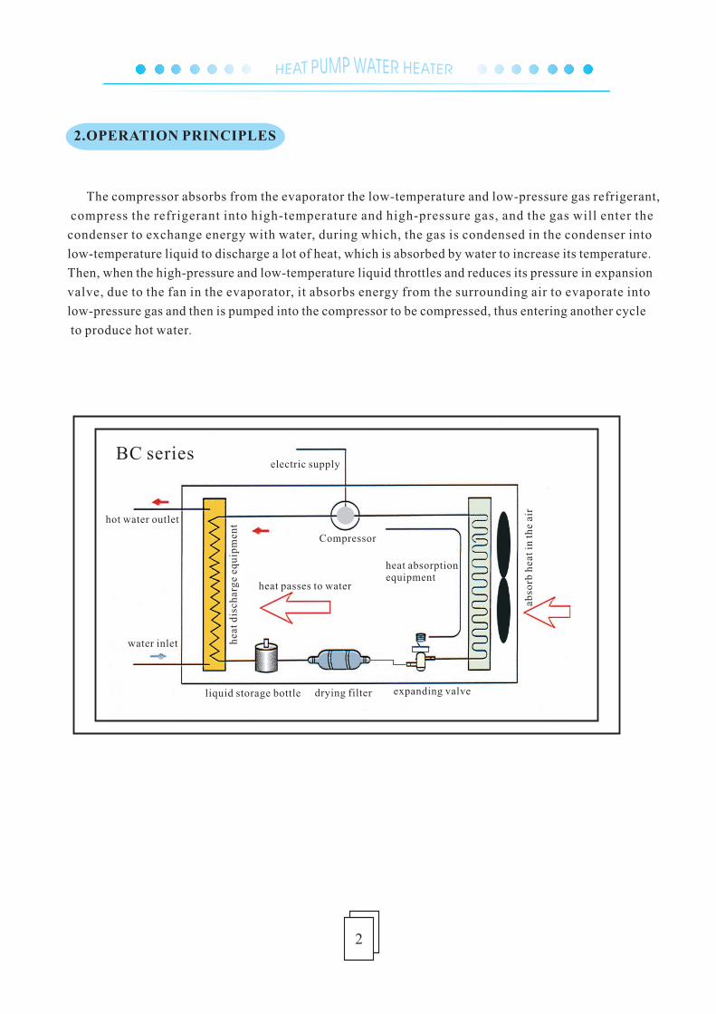
The compressor absorbs from the evaporator the low-temperature and low-pressure gas refrigerant,
compress the refrigerant into high-temperature and high-pressure gas, and the gas will enter the
condenser to exchange energy with water, during which, the gas is condensed in the condenser into
low-temperature liquid to discharge a lot of heat, which is absorbed by water to increase its temperature.
Then, when the high-pressure and low-temperature liquid throttles and reduces its pressure in expansion
valve, due to the fan in the evaporator, it absorbs energy from the surrounding air to evaporate into
low-pressure gas and then is pumped into the compressor to be compressed, thus entering another cycle
to produce hot water.
2.OPERATION PRINCIPLES
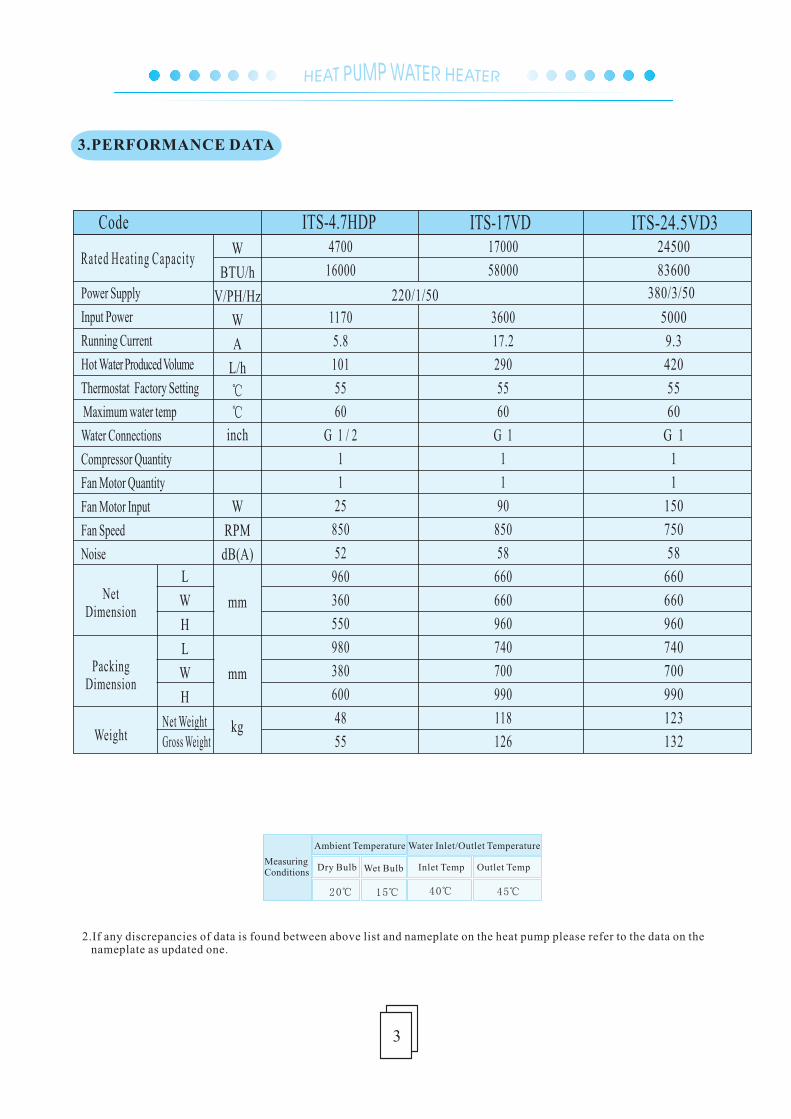
2.If any discrepancies of data is found between above list and nameplate on the heat pump please refer to the data on the nameplate as updated one.
20℃ 15℃ 40℃ 45℃
MeasuringConditions
Ambient Temperature Water Inlet/Outlet Temperature
Dry Bulb Wet Bulb Inlet Temp Outlet Temp
L
W
H
L
W
H
W
BTU/h
V/PH/Hz
W
A
L/h
℃
℃
inch
W
RPM
dB(A)
mm
mm
kg
220/1/50
ITS-4.7HDP4700
16000
1170
5.8
101
55
60
G 1 / 2
1
1
25
850
52
960
360
550
980
380
600
48
55
Power Supply
Input Power
Running Current
Hot Water Produced Volume
Thermostat Factory Setting
Maximum water temp
Water Connections
Compressor Quantity
Fan Motor Quantity
Fan Motor Input
Fan Speed
Noise
Rated Heating Capacity
Code
NetDimension
PackingDimension
WeightNet WeightGross Weight
L
W
H
L
W
H
ITS-17VD17000
58000
3600
17.2
290
55
60
G 1
1
1
90
850
58
660
660
960
740
700
990
118
126
3
3.PERFORMANCE DATA
380/3/50
ITS-24.5VD324500
83600
5000
9.3
420
55
60
G 1
1
1
150
750
58
660
660
960
740
700
990
123
132
4
ITS-4.7HDP
2 2.5mm 13AWG 24.0mm /11AWG
ITS-17VD ITS-24.5VD3
24.0mm /11AWG
Code
Specs
2.Installation 4.INSTALLATION
A
C
D
B
G H
FE
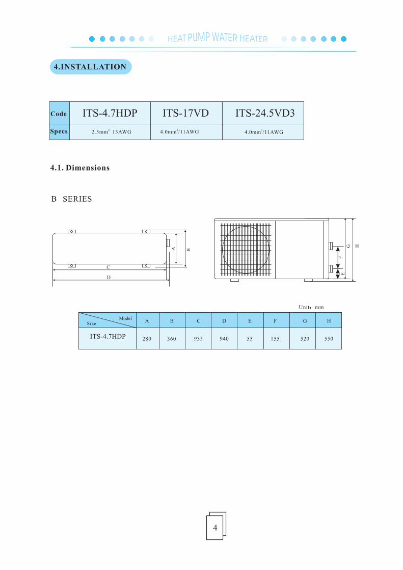
B SERIES
B C D E F G H
ITS-4.7HDP
A
280 360 935 940 55 155 520 550
Model
Size
Unit:mm
4.1. Dimensions
5
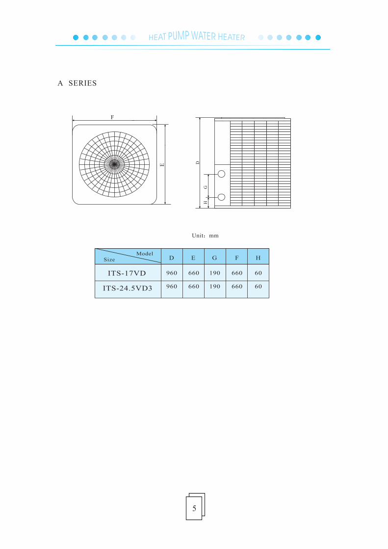
A SERIES
D
HG
F
E
D GE HF
Unit:mm
ITS-17VD
ITS-24.5VD3
960
960
660
660
190
190
660
660
60
60
Model
Size
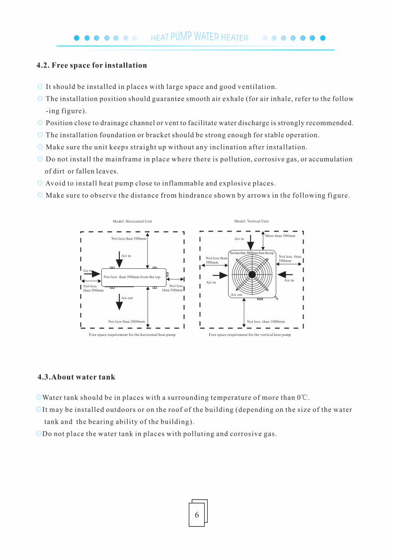
4.2. Free space for installation
6
◎
◎
◎
Water tank should be in places with a surrounding temperature of more than 0℃.
It may be installed outdoors or on the roof of the building (depending on the size of the water
tank and the bearing ability of the building).
Do not place the water tank in places with polluting and corrosive gas.
4.3.About water tank
◎
◎
◎
◎
◎
◎
◎
◎
It should be installed in places with large space and good ventilation.
The installation position should guarantee smooth air exhale (for air inhale, refer to the follow
-ing figure).
Position close to drainage channel or vent to facilitate water discharge is strongly recommended.
The installation foundation or bracket should be strong enough for stable operation.
Make sure the unit keeps straight up without any inclination after installation.
Do not install the mainframe in place where there is pollution, corrosive gas, or accumulation
of dirt or fallen leaves.
Avoid to install heat pump close to inflammable and explosive places.
Make sure to observe the distance from hindrance shown by arrows in the following figure.
Air out
Air in
Air in
Not less than 500mm
Not less than 2000mm
Not less than 500mm
Not less than 500mm
Not less than 500mm from the top
Free space requirement for the horizontal heat pump
Air in
Air inAir in
More than 500mm
Not less than 500mm
Not less than 500mm
Not less than 1000mm
Not less than 3000mm from the top
Air out
Free space requirement for the vertical heat pump
Model: Vertical UnitModel: Horizontal Unit
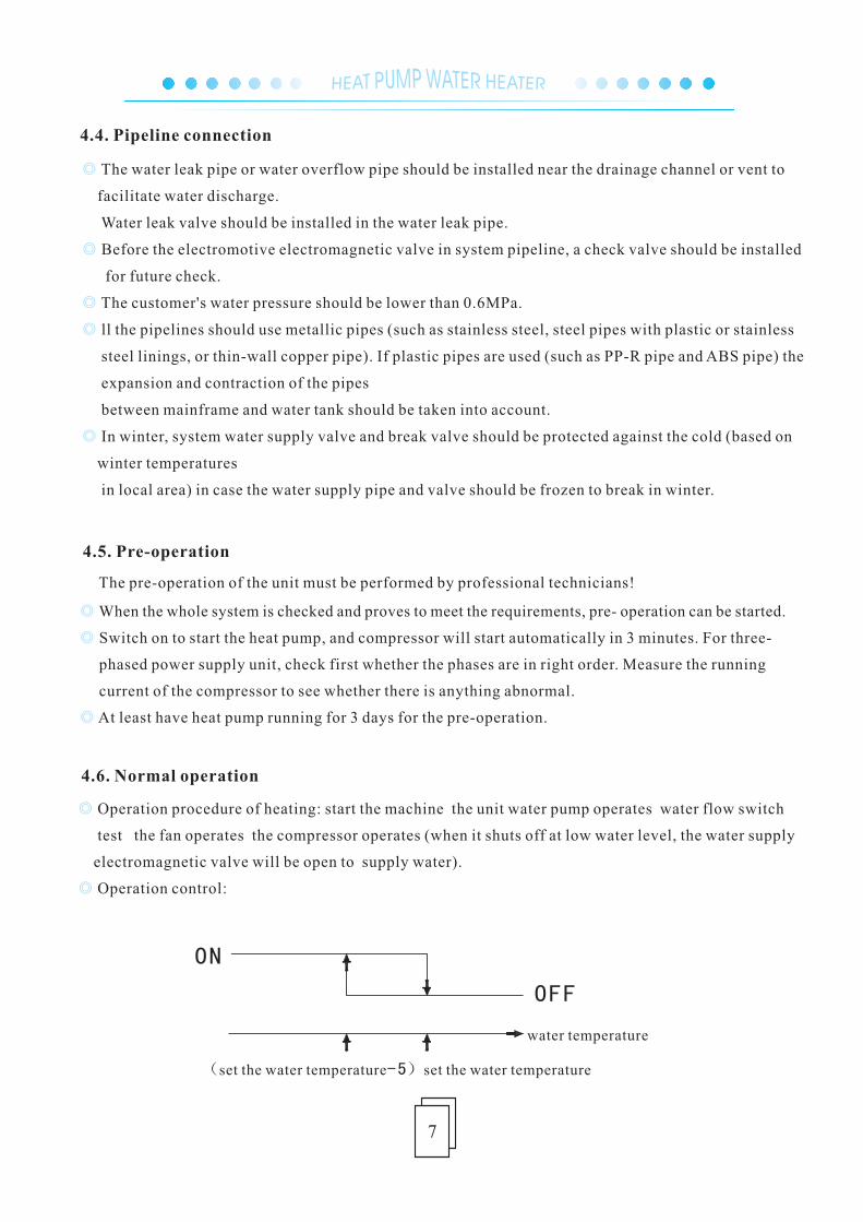
( -5)set the water temperature set the water temperature
ON
water temperature
OFF
7
Operation procedure of heating: start the machine the unit water pump operates water flow switch
test the fan operates the compressor operates (when it shuts off at low water level, the water supply
electromagnetic valve will be open to supply water).
Operation control:
◎
◎
The pre-operation of the unit must be performed by professional technicians!
◎
◎
◎
When the whole system is checked and proves to meet the requirements, pre- operation can be started.
Switch on to start the heat pump, and compressor will start automatically in 3 minutes. For three-
phased power supply unit, check first whether the phases are in right order. Measure the running
current of the compressor to see whether there is anything abnormal.
At least have heat pump running for 3 days for the pre-operation.
◎
◎
◎
◎
◎
The water leak pipe or water overflow pipe should be installed near the drainage channel or vent to
facilitate water discharge.
Water leak valve should be installed in the water leak pipe.
Before the electromotive electromagnetic valve in system pipeline, a check valve should be installed
for future check.
The customer's water pressure should be lower than 0.6MPa.
ll the pipelines should use metallic pipes (such as stainless steel, steel pipes with plastic or stainless
steel linings, or thin-wall copper pipe). If plastic pipes are used (such as PP-R pipe and ABS pipe) the
expansion and contraction of the pipes
between mainframe and water tank should be taken into account.
In winter, system water supply valve and break valve should be protected against the cold (based on
winter temperatures
in local area) in case the water supply pipe and valve should be frozen to break in winter.
4.4. Pipeline connection
4.6. Normal operation
4.5. Pre-operation
8
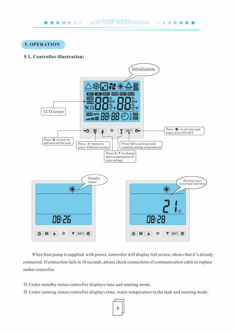
Standby status
5.1. Controller illustration:
When heat pump is supplied with power, controller will display full screen, shows that it’s already
connected. If connection fails in 10 seconds, please check connections of communication cable or replace
anther controller.
◎ Under standby status controller displays time and running mode.
◎ Under running status controller displays time, water temperature in the tank and running mode.
Running statusActual tank water temp.
5. OPERATION
9
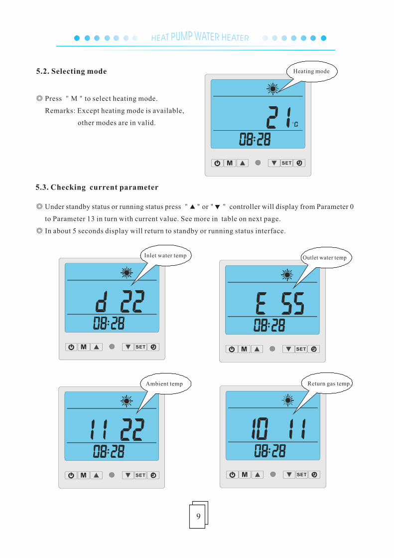
5.2. Selecting mode
◎ Press "M"to select heating mode.
Remarks: Except heating mode is available,
other modes are in valid.
5.3. Checking current parameter
◎ Under standby status or running status press " "or" " controller will display from Parameter 0
to Parameter 13 in turn with current value. See more in table on next page.
◎ In about 5 seconds display will return to standby or running status interface.
10
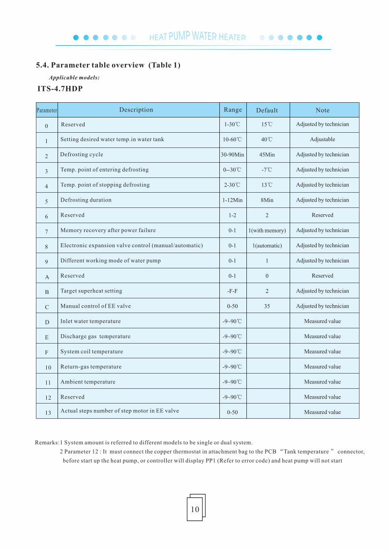
Remarks:1 System amount is referred to different models to be single or dual system.
2 Parameter 12 : It must connect the copper thermostat in attachment bag to the PCB “Tank temperature ” connector,
before start up the heat pump, or controller will display PP1 (Refer to error code) and heat pump will not start
5.4. Parameter table overview (Table 1)
0
1
2
3
4
5
6
7
8
9
A
B
C
D
E
F
10
11
12
13
Parameter Description Range Default Note
Reserved
Setting desired water temp.in water tank
Defrosting cycle
Temp. point of entering defrosting
Temp. point of stopping defrosting
Defrosting duration
Reserved
Memory recovery after power failure
Electronic expansion valve control (manual/automatic)
Different working mode of water pump
Reserved
Target superheat setting
Manual control of EE valve
Inlet water temperature
Discharge gas temperature
System coil temperature
Return-gas temperature
Ambient temperature
Reserved
Actual steps number of step motor in EE valve
1-30℃
10-60℃
30-90Min
0--30℃
2-30℃
1-12Min
1-2
0-1
0-1
0-1
0-1
-F-F
0-50
-9~90℃
-9~90℃
-9~90℃
-9~90℃
-9~90℃
-9~90℃
0-50
15℃
40℃
45Min
-7℃
13℃
8Min
2
1(with memory)
1(automatic)
1
0
2
35
Adjusted by technician
Adjustable
Adjusted by technician
Adjusted by technician
Adjusted by technician
Adjusted by technician
Reserved
Adjusted by technician
Adjusted by technician
Adjusted by technician
Reserved
Adjusted by technician
Adjusted by technician
Measured value
Measured value
Measured value
Measured value
Measured value
Measured value
Measured value
Αpplicable models:
ITS-4.7HDP
11
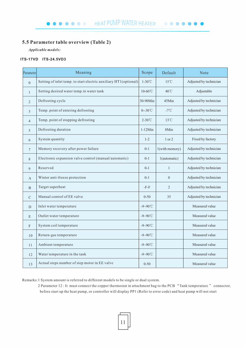
Remarks:1 System amount is referred to different models to be single or dual system.
2 Parameter 12 : It must connect the copper thermostat in attachment bag to the PCB “Tank temperature ” connector,
before start up the heat pump, or controller will display PP1 (Refer to error code) and heat pump will not start
5.5 Parameter table overview (Table 2)
0
1
2
3
4
5
6
7
8
9
A
B
C
D
E
F
10
11
12
13
Parameter Meaning Scope Default Note
Setting of inlet temp. to start electric auxiliary HT1(optional)
Setting desired water temp.in water tank
Defrosting cycle
Temp. point of entering defrosting
Temp. point of stopping defrosting
Defrosting duration
System quantity
Memory recovery after power failure
Electronic expansion valve control (manual/automatic)
Reserved
Winter anti-freeze protection
Target superheat
Manual control of EE valve
Inlet water temperature
Outlet water temperature
System coil temperature
Return-gas temperature
Ambient temperature
Water temperature in the tank
Actual steps number of step motor in EE valve
1-30℃
10-60℃
30-90Min
0--30℃
2-30℃
1-12Min
1-2
0-1
0-1
0-1
0-1
-F-F
0-50
-9~90℃
-9~90℃
-9~90℃
-9~90℃
-9~90℃
-9~90℃
0-50
15℃
40℃
45Min
-7℃
13℃
8Min
1 or 2
1(with memory)
1(automatic)
1
0
2
35
Adjusted by technician
Adjustable
Adjusted by technician
Adjusted by technician
Adjusted by technician
Adjusted by technician
Fixed by factory
Adjusted by technician
Adjusted by technician
Adjusted by technician
Adjusted by technician
Adjusted by technician
Adjusted by technician
Measured value
Measured value
Measured value
Measured value
Measured value
Measured value
Measured value
Αpplicable models:
ITS-17VD ITS-24.5VD3
12
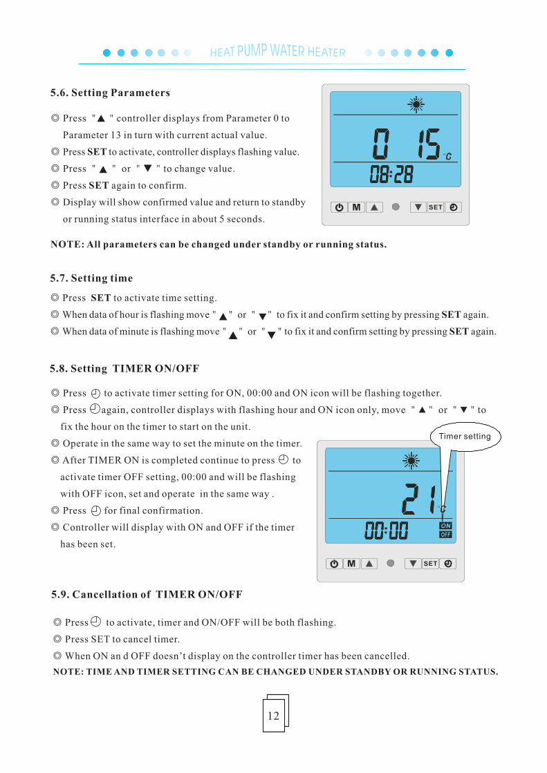
◎ Press " "controller displays from Parameter 0 to
Parameter 13 in turn with current actual value.
◎ Press SET to activate, controller displays flashing value.
◎ Press " " or " "to change value.
◎ Press SET again to confirm.
◎ Display will show confirmed value and return to standby
or running status interface in about 5 seconds.
NOTE: All parameters can be changed under standby or running status.
5.7. Setting time
◎ Press SET to activate time setting.
◎ When data of hour is flashing move" " or " " to fix it and confirm setting by pressing SET again.
◎ When data of minute is flashing move" " or " "to fix it and confirm setting by pressing SET again.
5.8. Setting TIMER ON/OFF
◎ Press to activate timer setting for ON, 00:00 and ON icon will be flashing together.
◎ Press again, controller displays with flashing hour and ON icon only, move " " or " "to
fix the hour on the timer to start on the unit.
◎ Operate in the same way to set the minute on the timer.
◎ After TIMER ON is completed continue to press to
activate timer OFF setting, 00:00 and will be flashing
with OFF icon, set and operate in the same way .
◎ Press for final confirmation.
◎ Controller will display with ON and OFF if the timer
has been set.
◎ Press to activate, timer and ON/OFF will be both flashing.
◎ Press SET to cancel timer.
◎ When ON an d OFF doesn’t display on the controller timer has been cancelled.
5.9. Cancellation of TIMER ON/OFF
NOTE: TIME AND TIMER SETTING CAN BE CHANGED UNDER STANDBY OR RUNNING STATUS.
5.6. Setting Parameters
13
Wire controller
PP1
PP2
PP3
PP4
PP5
PP7
EE1
EE2
EE3
EE4
EE8
☆●(1 flashes & 1 pause)
☆☆●(2 flashes & 1 pause)
☆☆☆●(3 flashes & 1 pause)
☆☆☆☆●(4 flashes & 1 pause)
☆☆☆☆☆●(5 flashes & 1 pause)
☆☆☆☆☆☆●(6 flashes & 1 pause)
☆☆☆☆☆☆☆●(7 flashes & 1 pause)
☆☆☆☆☆☆☆☆●(8 flashes & 1 pause)
☆☆☆☆☆☆☆☆☆● (9 flashes & 1 pause)
☆☆☆☆……(continuous flashes)
PP6
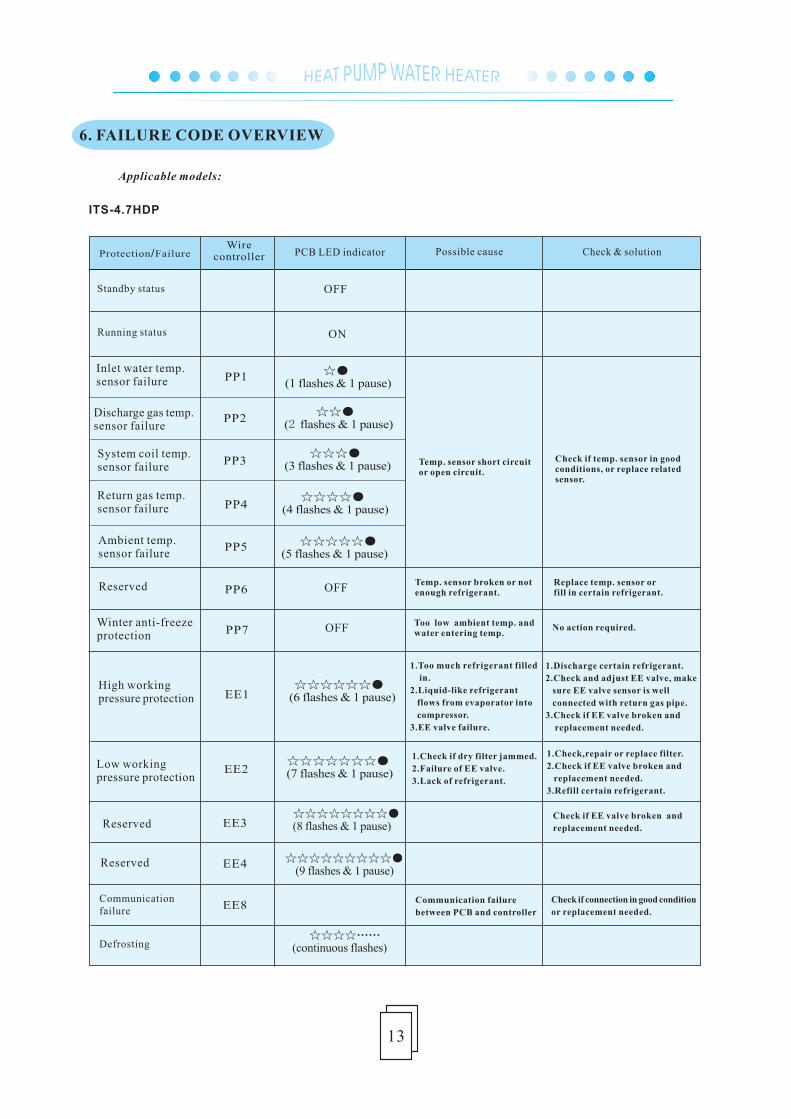
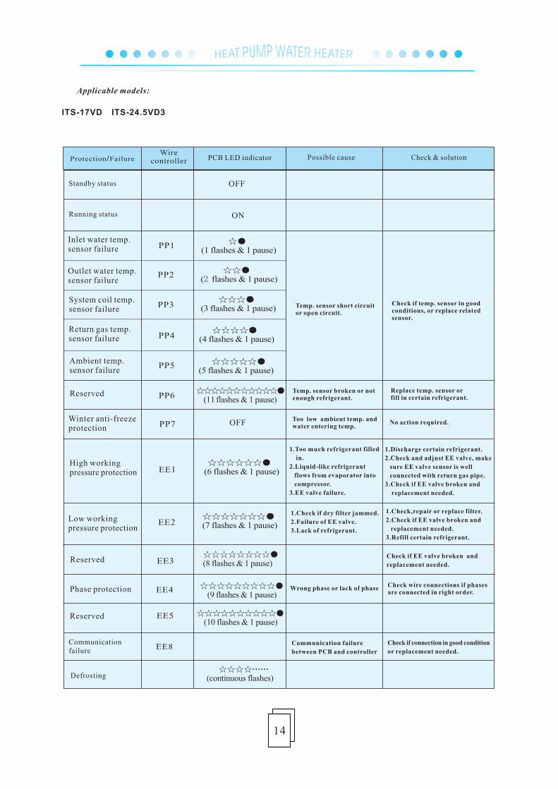
Communication failure
Defrosting
Standby status
Communication failure
between PCB and controller
Check if connection in good condition
or replacement needed.
Check if EE valve broken and
replacement needed.
1.Check if dry filter jammed.
2.Failure of EE valve.
3.Lack of refrigerant.
1.Too much refrigerant filled
in.
2.Liquid-like refrigerant
flows from evaporator into
compressor.
3.EE valve failure.
Too low ambient temp. and water entering temp.
1.Discharge certain refrigerant.
2.Check and adjust EE valve, make
sure EE valve sensor is well
connected with return gas pipe.
3.Check if EE valve broken and
replacement needed.
Temp. sensor broken or not enough refrigerant.
Temp. sensor short circuitor open circuit.
Check if temp. sensor in goodconditions, or replace relatedsensor.
1.Check,repair or replace filter.
2.Check if EE valve broken and
replacement needed.
3.Refill certain refrigerant.
No action required.
Replace temp. sensor orfill in certain refrigerant.
Reserved
Reserved
Low working pressure protection
High working pressure protection
Winter anti-freezeprotection
Reserved
Ambient temp.sensor failure
Return gas temp.sensor failure
System coil temp.sensor failure
Discharge gas temp.sensor failure
Inlet water temp. sensor failure
Running status
OFF
OFF
ON
OFF
Protection/Failure PCB LED indicator Possible cause Check & solution
6. FAILURE CODE OVERVIEW
Applicable models:
ITS-4.7HDP
14
Wire controller
PP1
PP2
PP3
PP4
PP5
PP7
EE1
EE2
EE3
EE4
EE8
☆●(1 flashes & 1 pause)
☆☆●(2 flashes & 1 pause)
☆☆☆●(3 flashes & 1 pause)
☆☆☆☆●(4 flashes & 1 pause)
☆☆☆☆☆●(5 flashes & 1 pause)
☆☆☆☆☆☆●(6 flashes & 1 pause)
☆☆☆☆☆☆☆●(7 flashes & 1 pause)
☆☆☆☆☆☆☆☆●(8 flashes & 1 pause)
☆☆☆☆☆☆☆☆☆● (9 flashes & 1 pause)
☆☆☆☆……(continuous flashes)
PP6
Communication failure
Defrosting
Standby status
Communication failure
between PCB and controller
Check if connection in good condition
or replacement needed.
Check if EE valve broken and
replacement needed.
1.Check if dry filter jammed.
2.Failure of EE valve.
3.Lack of refrigerant.
1.Too much refrigerant filled
in.
2.Liquid-like refrigerant
flows from evaporator into
compressor.
3.EE valve failure.
Too low ambient temp. and water entering temp.
1.Discharge certain refrigerant.
2.Check and adjust EE valve, make
sure EE valve sensor is well
connected with return gas pipe.
3.Check if EE valve broken and
replacement needed.
Temp. sensor short circuitor open circuit.
Check if temp. sensor in goodconditions, or replace relatedsensor.
1.Check,repair or replace filter.
2.Check if EE valve broken and
replacement needed.
3.Refill certain refrigerant.
No action required.
Replace temp. sensor orfill in certain refrigerant.
Phase protection
Reserved
Low working pressure protection
High working pressure protection
Winter anti-freezeprotection
Reserved
Ambient temp.sensor failure
Return gas temp.sensor failure
System coil temp.sensor failure
Outlet water temp.sensor failure
Inlet water temp. sensor failure
Running status
OFF
ON
OFF
Protection/Failure PCB LED indicator Possible cause Check & solution
Wrong phase or lack of phase Check wire connections if phases are connected in right order.
☆☆☆ ☆☆☆☆☆☆● (10 flashes & 1 pause)
☆Reserved EE5
Temp. sensor broken or not enough refrigerant.
☆☆☆ ☆ ☆☆☆☆☆● (11 flashes & 1 pause)
☆ ☆
ITS-17VD ITS-24.5VD3
Applicable models:
15
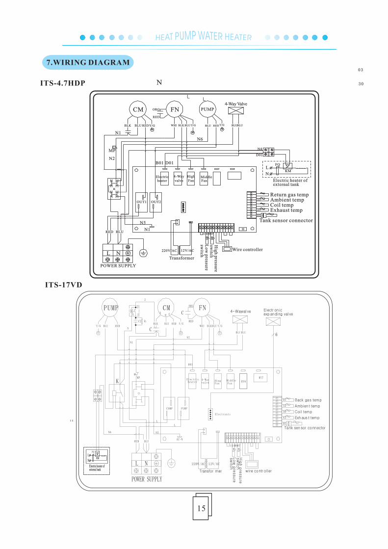
ITS-4.7HDP
ITS-17VD
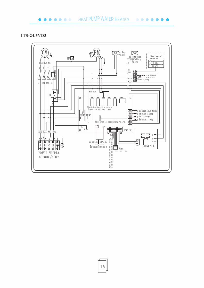
7.WIRING DIAGRAM
POWER SUPPLY
BLURED
Y/GBLU RED BLUBLUWHI BLK BLU Y/G
RED
ORG
BLK BLU REDY/G
Wire controller
FQ
Electric heater of
L
N
A1 A2
KM
external tank
N2
LL
heaterElectric 4-Way
valveMiddleFanFan
High
OUT2OUT1
Exhaust temp
Return gas tempAmbient tempCoil temp
Tank sensor connector
Transformer
N5
D01
D01
N4
N6
MPP
1110 0807
P
05
42
30
32
03
N
PUMP
N1
FNCM
NL12V/AC220V/AC
LP HPP
N1
B01
4-Way Valve
Hig
h pressu
resw
itchL
ow
pressu
resw
itch
BLURED
wire contr ol ler
RY7
BLUBLU
PUMPCOMP
RY6
4-Way val ve Electr on icexp anding val ve
Transfor mer
P P
07081011
Lo
wp
ressure
sw
itch
sw
itch
Hig
hp
ressure
03
32
30
42
05
Tank sen sor connector
Coi l temp
Ambien t temp
Back gas temp
Exh aus t temp
P
6
N1
N2
FNCM
NL 12V/AC220V/AC
AC-N
Electronic
RED
WHI BLK
SR C
C
C
BLU
ORG
BLK BLU RED Y/GY/G
L
L
N6 N5
D01
MP
K
PUMP
REDBLUY/G
valve4-Way Electric
heater HingFan
MiddleFan
2
C2
K
2
15
Rf
5
FQ
Electric heater of
L
N
A1 A2
KM
external tank
16
ITS-24.5VD3
MP
4- Wa yva lv eCM
U V W
N1
N
A1
A2
R S T
B
1 3 5
2 4 6
RE D BL K WH I
L1 1 L2 1 L3 1
WH IBL KRE D BU L
C NBA
AC 38 0V /5 0H z
FMEl ec tr on icex pa nd in g
va lv e6
D0 1B0 1
N1N5
L
L
CO MP PU MP
El ec tr iche at er
4- Wa yva lv e
Hi ngFa n
Mi dd leFa n
El ec tr on ic ex pa nd in g va lv e
Tr an sf or me r
22 0V/ AC 12 V/ AC
121110090807060504030201 13
HPLP
High pressure switch
Low pressure switch
07081011
Co il te mpAm bi en t te mpRe tu rn ga s te mp
Ex ha us t te mp
Ta nk se ns orco nn ec to r
23
22
21
20
18
19
17
14
16
15
03
32
30
42
05
PO WE R SU PP LY
Wi reco nt ro ll er
N4
D0 1
Wa te r pu mp
05
05
FQ
Electri c heater of
L
N
A1 A2
KM
external tank
8. MAINTENANCE
.
.
.
.
.
.
.
.
.
.
.
.
The heat pump water heater is highly automatic equipment, which is checked periodically over its
unit state in application. If the unit can be maintained effectively for a long time, the operation reliability
and lifespan of the unit will be greatly enhanced.
1 The water filter installed outside the unit should be cleaned periodically to ensure a clean water supply
in the system in case the unit may be damaged due to the blocked dirty water filter.
2 In using and maintaining this unit, the customer should pay attention to this point: all the safety
protection equipment in the unit has been set properly before leaving the factory, therefore, it is for
-bidden to adjust them without permission.
3 Check frequently whether the power supply and electrical system connection of the unit are firm and
whether the electrical components operate abnormally. If there is, repair or replace in time.
4 Check frequently whether water supply of the system, water tank safety valve, liquid level controller,
and air discharge equipment operate normally in case air should enter the system to lead to decreased
water cycle so as to influence the heating ability of the unit and reliability of unit operation.
5 Check whether water pump and water pipe valves can operate normally, and whether there is any leak
-age in water pipeline and water pipe connections.
6 The surrounding of the unit should be kept clean with good ventilation. Clean regularly (1-2 months)
the air side heat exchanger to maintain a good heat exchange effect.
7 Check frequently the operation state of each part of the unit. Check whether there is oil dirt in unit
pipeline connection and air inhale valve to ensure there is no leakage of the unit refrigerant.
8 Do not pile any other object around the unit in case the air exhale should be blocked. The surrounding
of the unit should be kept dry and clean with good ventilation.
9 If the machine will be stopped for a long time, discharge the water in unit pipeline, cut off power supply,
cover with protection shield, and check the system comprehensively before starting the unit to operate
again.
10 If there is anything wrong with the unit and the customer can not solve it, make a phone call to local
special service department of our company so that we could send professional staff to fix it in time.
11 For cleaning of mainframe condenser, we suggest that 50℃-60℃ hot phosphate liquid with a density
of 15% can be used to clean it. Start the mainframe-equipped cycle water pump to clean for three hours
and then clean with running water 3 times. (In pipeline installation, it is suggested to reserve a tee
connection and block one of the connection with silk block) so as to connect pipes in cleaning. It is
forbidden to use corrosive detergent to clean the condenser.
12 Furring should be removed from the water tank after using for a period of time (usually two months
depending on water quality in local area).
17